

Page 1
L8542722
07/2011 rev 0
CBY.24V
UNIONE NAZIONALE COSTRUTTORI
AUTOMATISMI PER CANCELLI, PORTE
SERRANDE ED AFFINI
Page 2
1
2
CBY.24V
12V
DA.BT2/DA.BT6
Pb Battery
12V
+ -
CBY.24V
NiMh Battery
RED
BLACK
NTC+ -
BLUE
2
Page 3

CENTRALE DI COMANDO
CONTROL UNIT
STEUEREINHEIT
CENTRALE DE COMMANDE
CENTRAL DE MANDO
CENTRALKA STEROWANIA
3
4
2 4 s c
V M s c
V M t r s
2 4 t r s
0 t r s
0 s c
CBY.24V
CENTRALE DI COMANDO
CONTROL UNIT
STEUEREINHEIT
CENTRALE DE COMMANDE
CENTRAL DE MANDO
CENTRALKA STEROWANIA
2 4 V
0
0
0
230
24
3
Page 4

2 4 s c
V M s c
V M t r s
2 4 t r s
0 t r s
0 s c
CBY.24V
CENTRALE DI COMANDO
CONTROL UNIT
STEUEREINHEIT
CENTRALE DE COMMANDE
CENTRAL DE MANDO
CENTRALKA STEROWANIA
2 4 V V M O T
0
0
0
230
V2
24
V1
V3
5
4
Page 5

CBY.24V ITALIANO
Scheda caricabatteria per il collegamento delle batterie di
emergenza a centrali di comando per motori 24Vdc.
E’ possibile utilizzare sia batterie al piombo sia batterie
NiMh:
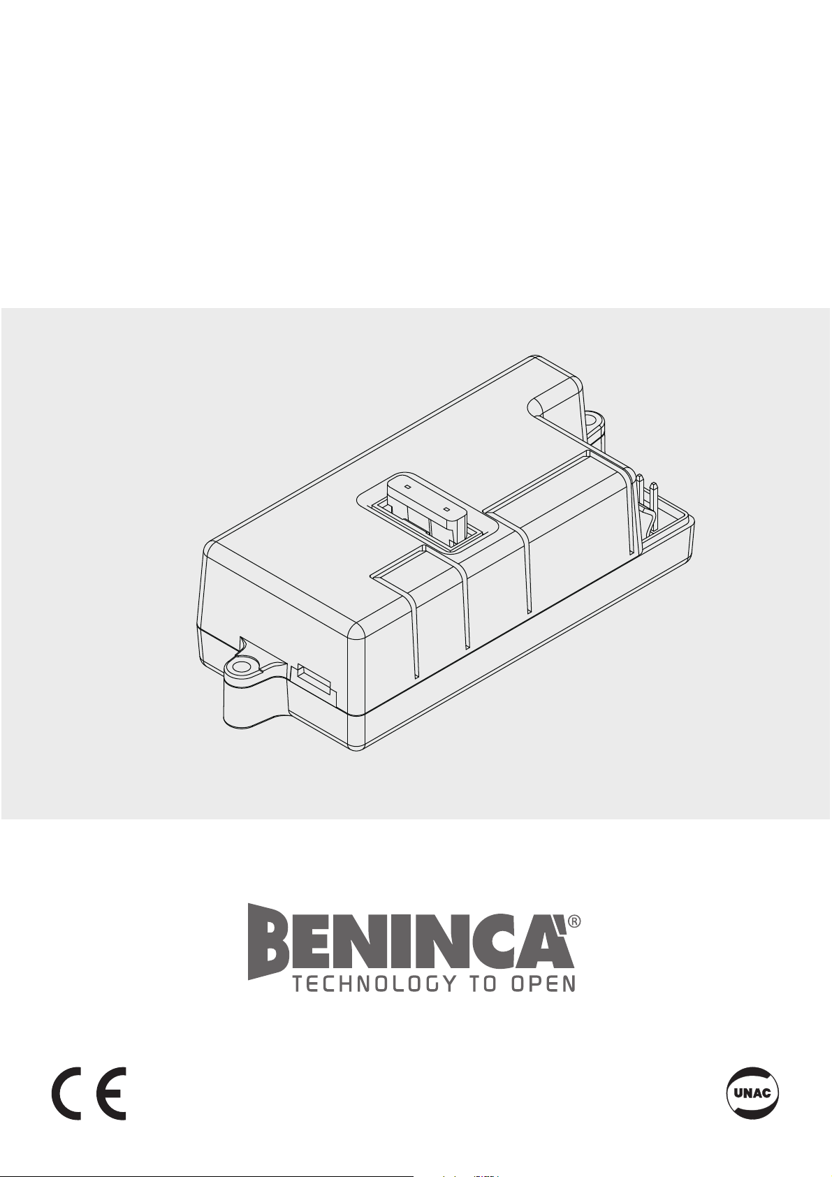
- Collegamento delle batterie al piombo mod. DA.BT2/
DA.BT6
In figura 1 è illustrato il collegamento delle batterie da 12V al
piombo. Il terminale NTC non va collegato.
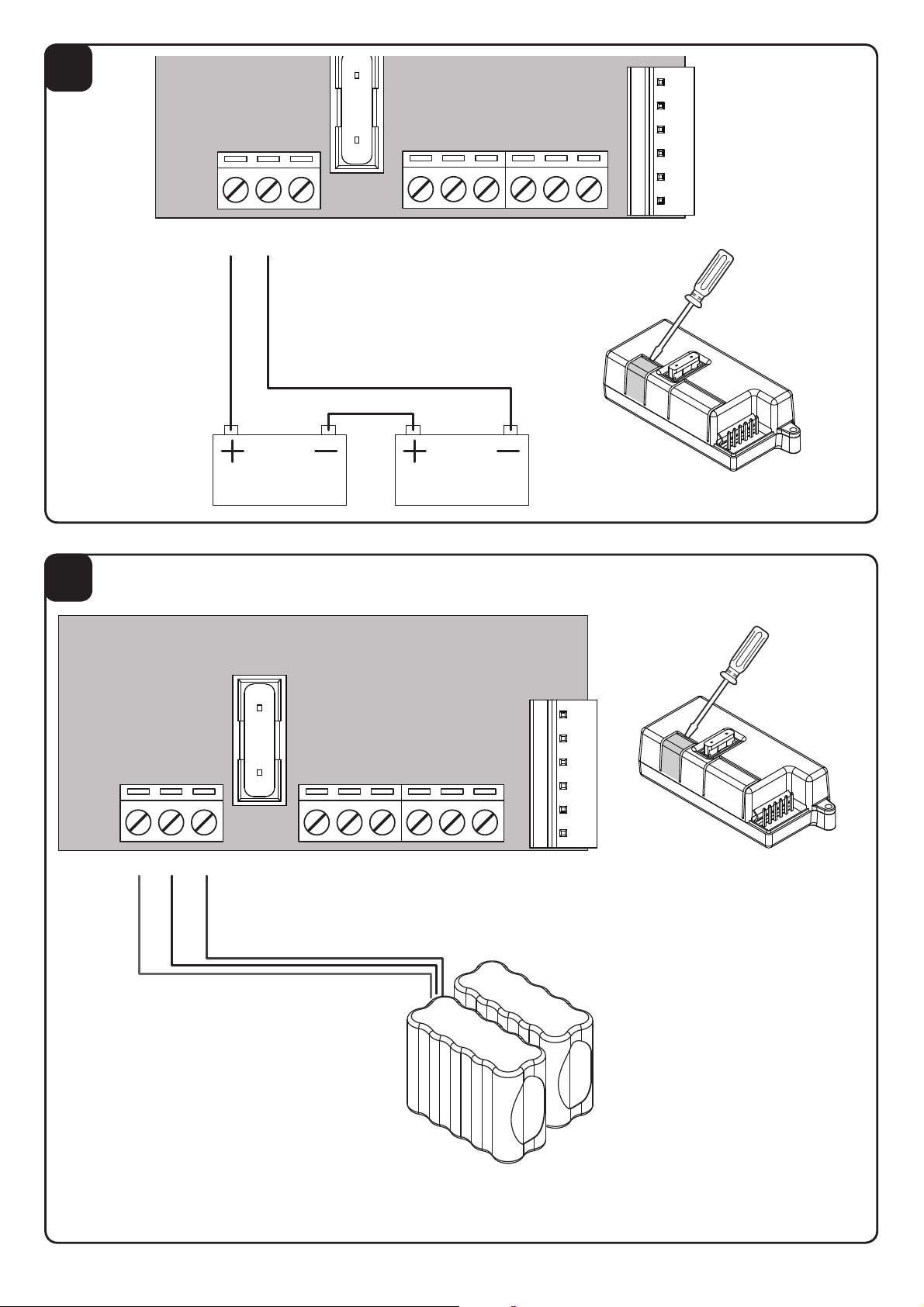
- Collegamento delle batterie NiMh
In figura 2 è illustrato il collegamento delle kit batterie NiMh
da 24V.
IMPORTANTE: E’ necessario tagliare il connettore
rapido delle batterie NiMh, per evitare cortocircuiti,
tagliare un filo alla volta.
Collegare i tre fili rispettando i colori:
Rosso:+ / Nero:- / Blu:NTC (sensore termico).
Per il collegamento alla centrale di comando sono disponibili
3 diverse modalità a seconda del tipo di centrale:
- Centrale con connettore rapido per caricabatterie:
Se la centrale dispone di connettore rapido per il
caricabatterie è sufficiente collegare con il cavo fornito in
dotazione i due connettori come evidenziato in Figura 3.
NOTA: Alcune centrali dispongono di connettori rapidi per
altri utilizzi, ad esempio per ricevitori radio.
Verificate sul manuale fornito con la centrale l’effettiva
presenza del connettore rapido per caricabatterie, prima di
procedere al cablaggio.
- Centrale con ingressi 0V/24V:
Se la centrale è collegata al trasformatore per mezzo dei
due soli collegamenti (0V/24V), scollegate il trasformatore
e, dopo aver rimosso la copertura del morsetto, effettuate i
cablaggi evidenziati in Figura 4. e’ necessario effettuare un
ponticello tra i morsetti VMTRS e 24 TRS.
- Centrale con ingressi 0V/24V e ingresso velocità
motore:
Alcune centrali 24V sono dotate di un collegamento
aggiuntivo che regola la velocità del motore su diversi valori
disponibili nel trasformatore.
In questo caso scollegate il trasformatore e, dopo aver
rimosso la copertura del morsetto, effettuate i cablaggi
evidenziati in Figura 5.
Nella tabella di seguito viene descritta in dettaglio la
morsettiera.
ATTENZIONE!
Durante il funzionamento in assenza di rete, l’uscita
accessori 24Vac della centrale, risulta polarizzata.
E’ indispensabile verificare il corretto collegamento
degli accessori, come riportato nel manuale istruzioni
della centrale di comando.
Funzioni Ingressi/Uscite
+ + 24Vdc dalla batteria di emergenza
- - 24Vdc dalla batteria di emergenza
NTC Sensore Termico (solo per batterie NiMh)
0sc Collegare al connettore 0V della centrale
0trs Collegare al secondario 0V del trasformatore
24trs
Collegare al secondario 24V del trasformatore
(da 23 a 28Vac).
VMtrs
Collegare al secondario del trasformatore (da 15
a 30Vac). ATTENZIONE!: Seleziona la velocità di
funzionamento del motore. Fate riferimento alle
istruzioni della centrale di comando per il corretto collegamento.
VMsc Collegare al connettore VMot della centrale
24sc Collegare al connettore VAux della centrale.
Note.
Durante il normale funzionamento di rete la scheda provvede
al mantenimento della carica delle batterie.
Nel caso di assenza di rete la scheda fornisce alimentazione
attraverso le batterie. Un fusibile F10A protegge la centrale
durante il funzionamento con batteria di emergenza.
La batteria tampone funziona fino a che, scaricandosi
progressivamente, non raggiunge il valore di 18V.
Al raggiungimento di questo valore la batteria viene
scollegata.
Caratteristiche Tecniche:
Corrente di carica 200mA
Tensione di carica 27,2 Vdc
Tempo di carica
(per batterie 2Ah)
10 ore circa
CBY.24V ENGLISH
Battery charger card for the connection of emergency
batteries to control units for 24VDC motors.
Either lead batteries or NiMh batteries can be used:
- Connection to lead batteries model DA.BT2/DA.BT6
Figure 1 shows the connection of lead, 12V batteries.
Terminal NTC must not be connected.
- Connection of NiMh batteries
Figure 2 shows the connection of NiMh, 24Vbatteries.
IMPORTANT: The rapid connector of NiMh should be
cut. Cut one wire at a time to avert any short-circuits.
Connect the three wire while respecting the colours:
Red: +/Black: - /Blue: NTC (thermal sensor).
As regards the connection to the control unit, 3 different
ways are available, according to the type of control unit:
- Control unit with rapid connector for battery charger:
If the control unit is provided with a rapid connector for the
battery charger, it is sufficient to connect the two connectors
with the cable supplied, as shown in Figure 3.
NOTE: Some control units are provided with rapid
connectors for other uses, e.g. radio receivers.
Before proceeding to the wire connection, check on the
user’s manual supplied with the control unit that the rapid
connector is actually supplied for battery chargers.
- Control unit with 0V/24V inputs:
If the control unit is connected to the transformer through
only two connections (0V/24V), disconnect the transformer
and, after removing the terminal cover, carry out the wire
connections as shown in Figure 4. Terminals VMTRS and 24
TRS should be short-circuited.
- Control unit with 0V/24V inputs and motor speed input:
Some 24V control units are equipped with an additional wire
connection which regulates the motor speed to the various
values available in the transformer.
In this case, disconnect the transformer and, after removing
the terminal cover, carry out the wiring as shown in Figure
5.
The following table describes the terminal board in detail.
5
Page 6

CAUTION!
During operation, should a power failure occur, the 24V
accessory output of the control unit is polarised.
It is mandatory to check the correct operation of
accessories, as described in the user’s manual of the
control unit.
Input/Output functions
+ + 24VDC from the emergency battery
- - 24VDC from the emergency battery
NTC Thermal sensor (for NiMh batteries)
0sc Connect to 0V connector of the control unit
0trs
Connect to 0V secondary terminal of the transformer
24trs
Connect to the 24V secondary terminal of the
transformer (from 23 to 28VAC).
VMtrs
Connect to secondary terminal of the transformer (from 15 to 30VAC).
CAUTION!: Select the motor operating speed.
To perform a correct connection, make reference to instructions of the control unit.
VMsc
Connect to the Vmot connector of the control
unit
24sc Connect to the VAux of the control unit.
Notes.
During the normal network powering, the card maintains the
battery charged.
If a power failure occurs, the card powers the system
through the batteries. A F10A fuse protects the control unit
during operation with the emergency battery.
The buffer battery operates until 18V is reached. The charge
is reduced progressively. When this value is reached, the
battery is disconnected.
Specification:
Charge current 27.2 VDC
Charge voltage 27,2 Vdc
Charge time
(for 2Ah batteries)
10 ore circa
CBY.24V DEUTSCH
Karte des Batterieladegeräts, um Reservebatterien an die
Steuerzentralen von Motoren zu 24Vdc zu schließen.
Es können sowohl Blei- als auch NiMh-Batterien verwendet
werden:
- Anschluss der Bleibatterien Mod. DA.BT2/DA.BT6
Die Abbildung 1 zeigt den Anschluss der Bleibatterien zu
12V. Der Verbinder NTC muss nicht angeschlossen
werden.
- Anschluss der NiMh-Batterien
Die Abbildung 2 zeigt den Anschluss des Batteriesets NiMh
zu 12V.
WICHTIG: Der Schnellverbinder der NiMh-Batterien muss
abgeschnitten werden, um Kurzschlüsse zu vermeiden.
Einen Leiter nach dem anderen durchschneiden.
Die drei Leiter den Farben gemäß anschließen:
Rot:+ / Schwarz:- / Blau:NTC (Wärmefühler).
Je nach Steuerzentrale kann der Anschluss auf drei
verschiedene Weisen erfolgen:
- Zentrale mit Schnellverbinder für das
Batterieladegerät:
Wenn die Zentrale über einen Schnellverbinder für das
Ladegerät verfügt, genügt es die beiden Verbinder mit dem
mitgelieferten Kabel wie in Abb. 3 gezeigt, anzuschließen.
BEMERKUNG: Einige Zentralen sich mit Schnellverbinder für
andere Anwendungen, wie Funkempfänger ausgestattet.
Prüfen Sie anhand des mitgelieferten Handbuchs, ob die
Zentrale über einen Schnellverbinder für das Ladegerät
verfügt, bevor Sie die Anschlüsse vornehmen.
- Zentrale mit Eingängen 0V/24V:
Wenn die Zentrale an einem Transformator durch nur zwei
Anschlüsse (0V/24V) verbunden ist, den Transformator
abtrennen, die Klemmenabdeckung abnehmen und die
Anschlüsse laut Abbildung 4 vornehmen. Die Klemmen
VMTRS und 24 TRS müssen überbrückt werden.
- Zentrale mit Eingängen 0V/24V und Eingang für
Motorgeschwindigkeit:
Einige Zentralen zu 24V verfügen über einen zusätzlichen
Anschluss, der die Motorgeschwindigkeit regelt und den
unterschiedlichen Werten des Transformators anpasst.
In diesem Fall, zuerst den Transformator abtrennen und die
Klemmenabdeckung abnehmen, dann die Anschlüsse laut
Abb. 5 vornehmen.
In der nachstehenden Tabelle wird die Klemmleiste näher
beschrieben:
ACHTUNG!
Während des Betriebs ohne Stromversorgung durch
das Netz, ist der Ausgang Zubehör 24Vac der Zentrale
polarisiert.
Der richtige Anschluss des Zubehörs muss laut den
Gebrauchsanweisungen des Handbuchs geprüft
werden.
Funktionen Eingänge/Ausgänge
+ + 24Vdc der Reservebatterie
- + 24Vdc der Reservebatterie
NTC Wärmefühler (nur für NiMh-Batterie)
0sc An den Verbinder 0V der Zentrale schließen
0trs
An die Sekundärwicklung 0V des Trafos
schließen
24trs
An die Sekundärwicklung 24V des Trafos (zu 23
bis 28Vac) schließen
VMtrs
An die Sekundärwicklung des Trafos (zu 15 bis
30Vac) schließen ACHTUNG! Regelt die Geschwindigkeit des Motors. Für die Anschlüsse
beziehen Sie sich bitt auf die Anweisungen der
Steuerzentrale.
VMsc An den Verbinder VMot der Zentrale schließen
24sc An den Verbinder VAux der Zentrale schließen
Bemerkungen:
Während des normalen Netzbetriebs speist die Karte die
Batterien.
Wenn die Stromversorgung ausbleibt, versorgt die Karte
das Gerät mit Strom über die Batterien. Eine Sicherung
F10A schützt die Zentrale während des Betriebs mit der
Reservebatterie.
Die Pufferbatterie funktioniert Solange bis sie den Wert von
18V erreicht und erschöpft ist. Wenn dieser Wert erreicht
wird, wird die Batterie abgetrennt.
Technische Eigenschaften
Ladestrom 200mA
Ladespannung 27,2 Vdc
Ladezeit
(für Batterie 2Ah)
10 Stunden circa
6
 Loading...