

Page 1
Installation
Instructions
FIELD REPAIR KIT FOR THE BENDIX® SR-5™ TRAILER SPRING BRAKE VALVE
Spring Retainer
1/4" P.T. Service/Spring
Brake Reservoir (2)
Reservoir
Fitting
SR-5
Identication
Hole
Recall Campaign No. 16E045
Control Piston
Cover
Cover Screw
3
1/4" P.T.
Trailer Service
(Only on
SR-5 Valves with
Anti-Compounding)
3/8" P.T.
Delivery (4)
Exhaust
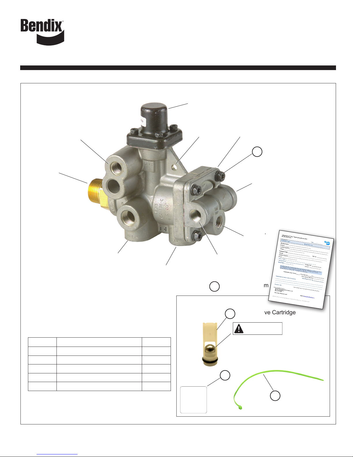
The Bendix SR-5 Field Repair Kit consists of the
following:
Key No. Description Qty.
1 Check Valve Cartridge 1
2 Green Tie Wrap 1
3 Cover Screw 1
4 Recall Claim Form 1
5 SR-5 Decal 1
®
Bendix
SR-5
O.K. By: ___________
Date: ____/____/____
BW8036
1/4" P.T.
Trailer Service
Recall Claim Form
4
1
Verify the ball is in the cartridge before
installation. If the ball slips out,contact
the Recall Assistance Center for a
replacement kit.
5
™
1/4" P.T.
Trailer
Supply
Check Valve Cartridge
IMPORTANT
Green Tie Wrap
2
Figure 1 – Bendix SR-5 Trailer Spring Brake Valve Exterior View
1
Page 2
GENERAL SAFETY GUIDELINES
WARNING! PLEASE READ AND
FOLLOW THESE INSTRUCTIONS
TO AVOID PERSONAL INJURY OR DEATH:
When working on or around a vehicle, the following
guidelines should be observed AT ALL TIMES:
▲Park the vehicle on a level surface, apply the parking
brakes and always block the wheels. Always wear personal
protection equipment.
▲Stop the engine and remove the ignition key when working
under or around the vehicle. When working in the engine
compartment, the engine should be shut off and the ignition
key should be removed. Where circumstances require that
the engine be in operation, EXTREME CAUTION should be
used to prevent personal injury resulting from contact with
moving, rotating, leaking, heated or electrically-charged
components.
▲Do not attempt to install, remove, disassemble or
assemble a component until you have read, and thoroughly
understand, the recommended procedures. Use only the
proper tools and observe all precautions pertaining to use
of those tools.
▲If the work is being performed on the vehicle’s air brake
system, or any auxiliary pressurized air systems, make
certain to drain the air pressure from all reservoirs before
beginning ANY work on the vehicle. If the vehicle is
equipped with a Bendix
™
dryer reservoir module, or a Bendix® AD-9si® air
DRM
dryer, be sure to drain the purge reservoir.
Following the vehicle manufacturer’s recommended
▲
procedures, deactivate the electrical system in a manner
that safely removes all electrical power from the vehicle
▲Never exceed manufacturer’s recommended pressures.
▲Never connect or disconnect a hose or line containing
pressure; it may whip and/or cause hazardous airborne
dust and dirt particles. Wear eye protection. Slowly open
connections with care, and verify that no pressure is
present. Never remove a component or plug unless you are
certain all system pressure has been depleted.
▲ Use only genuine Bendix
components and kits. Replacement hardware, tubing, hose,
fi ttings, wiring, etc. must be of equivalent size, type and
strength as original equipment and be designed specifi cally
for such applications and systems.
▲Components with stripped threads or damaged parts should
be replaced rather than repaired. Do not attempt repairs
requiring machining or welding unless specifi cally stated
and approved by the vehicle and component manufacturer.
▲Prior to returning the vehicle to service, make certain all
components and systems are restored to their proper
operating condition.
▲ For vehicles with Automatic Traction Control (ATC), the ATC
function must be disabled (ATC indicator lamp should be
ON) prior to performing any vehicle maintenance where
one or more wheels on a drive axle are lifted off the ground
and moving.
▲The power MUST be temporarily disconnected from the
radar sensor whenever any tests USING A DYNAMOMETER
are conducted on a vehicle equipped with a Bendix
Wingman
▲You should consult the vehicle manufacturer's operating
and service manuals, and any related literature, in
conjunction with the Guidelines above.
®
system.
®
AD-IS® air dryer system, a Bendix®
®
brand replacement parts,
GENERAL
This instruction sheet is intended to provide the necessary
information to service the Bendix® SR-5™ trailer spring brake
valve with an internal check valve cartridge. This is in
connection with Recall Campaign number 16E045.
This kit contains a check valve cartridge (1), a green tie wrap
(2) and one cover screw (3). The cover screw (3) is included
in the event one is damaged or lost during the installation
process.
PREPARATION
1. Use a wire brush to clean the exterior of the SR-5 valve
especially around the control piston cover. Use compressed
air to blow away loose debris to ensure that the valve does
not become contaminated when serviced.
2. Verify that the valve does not have a black or green tie
wrap already through the SR-5 identication hole. If a tie
wrap is present, this valve has already been serviced with
this kit. Return the vehicle into service.
3. Verify the valve meets the recall criteria as outlined in the
RECALL GUIDELINES section of this document. If the
valve falls outside of these parameters, return the vehicle
to service.
DISASSEMBLY
The installation of this kit requires that the control piston cover
be loosened, but not completely removed from the valve body.
1. Identify and disconnect all the air lines connected to the
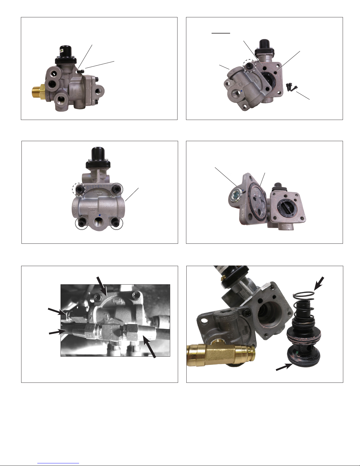
control piston cover. (Refer to Figure 4.)
.
2. It is necessary to rotate the tting in the trailer supply port
to complete this step. Rotate the tting counterclockwise
only (loosening) no more than 90°. (Refer to Figure 3.)
3. Remove cover screws "B", "C", and "D". While holding
the control piston cover in place, loosen cover screw "A"
4-5 turns. Carefully rotate the cover clockwise – pivoting
on screw "A" – until the check valve passage in the body is
visible. Hold the cover in this position to retain the control
piston in the body. (Refer to Figure 5.)
AT TENTION
OVER-ROTATING THE COVER MAY ALLOW THE
CONTROL PISTON AND RETURN SPRING TO COME
OUT OF THE VALVE. IF THIS HAPPENS, REMOVE
ANY DEBRIS THAT MAY ADHERE TO THE PISTON AND
REINSERT, SPRING FIRST. (Refer to Figure 7.)
4. Exercise caution to prevent damage to the cover seal as
shown in Figure 6.
®
2
Page 3
Bendix® SR-5™
Identication
Hole
(Indicates repair
Tie Wrap
is complete)
This port must remain
open. Do not install
the check valve here.
Control
Piston
Cover
A
Check Valve
Passage
Control
Piston
Cover
Screws
Figure 2 – Tie Wrap Location
A
D
Figure 3 – Control Piston Cover Screws
SR-5 Valve
B
C
Control
Piston
Cover
Figure 5 – Check Valve Passage
Control
Piston
Cover
Figure 6 – Cover Seal
Cover
Seal
Spring
Service
(Blue)
Trailer
Supply
(Red)
Figure 4 – Piston Cover Air Line Connections
Surelok
Supply
(Red)
Piston
Figure 7 – Piston and Spring
3
Page 4
ASSEMBLY
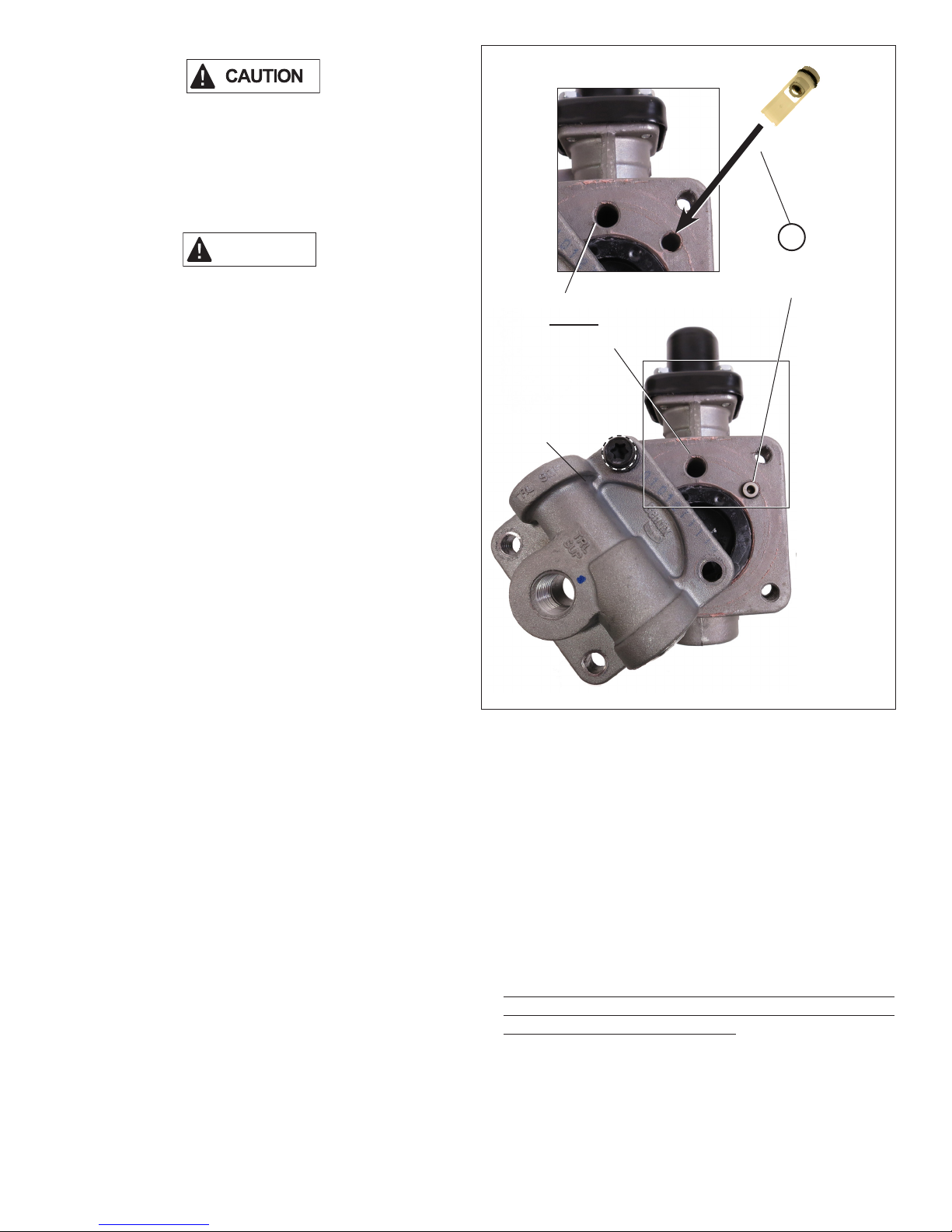
1. Ensure that the check valve cartridge (1) is intact as shown
in Figure 8.
2. Holding the larger diameter (o-ring end) of the check valve
cartridge (1), insert the pointed end into the air passage.
Push the check valve cartridge (1) in lightly with your nger
until it is ush with the body housing. (Refer to Figure 8.)
AT TENTION
THE CHECK VALVE CARTRIDGE (1) WILL FIT SNUGLY
INTO THE CORRECT AIR PASSAGE. DO NOT INSERT
THE CHECK VALVE CARTRIDGE (1) INTO THE LARGER
AIR PASSAGE.
3. Rotate the cover back into position and install the three
screws. Torque all four screws in a crossing pattern to
100 in-lbs. (A, C, D then B). (Refer to Figure 3.)
4. Reposition any ttings that may have been moved and
reconnect the air lines.
5. Perform the OPERATIONAL AND LEAKAGE TESTS
detailed below before placing the vehicle back into service.
OPERATIONAL AND LEAKAGE TESTS
This test can be performed by connecting the red trailer
gladhand to a tractor or an external air source. Check the air
source gauge against a gauge known to be accurate before
performing these tests.
1. Block all wheels or hold the vehicle by means other than
the air brakes: drain all pressure from the trailer reservoir.
This port must remain
open. Do not install
the check valve here.
Control
Piston
Cover
A
1
Check Valve
Cartridge
2. Install a gauge in the trailer reservoir(s). Connect the air
source to the red supply gladhand of the trailer on which
the Bendix® SR-5™ trailer spring brake valve is to be tested.
Build the trailer to full system pressure by placing the tractor
park control valve in the charge position, or by applying
an external air source. Make sure that the spring brake
chambers release before the reservoir starts to ll.
3. When full system pressure is reached – and the spring
brakes are fully released – apply a soap solution to the
control piston cover and ttings that were removed during
the repair. A one inch bubble in ve seconds is permissible.
4. Place the trailer air supply valve in the exhaust position,
or disconnect the external air source. The spring brakes
should apply. This will be evident by a full exhausting of
chamber pressure at the SR-5 valve exhaust port.
If the repair was completed correctly, the park brakes should
be set, and the reservoir pressure should hold steady with
no decay. If the valve does not perform properly, repeat the
installation procedure and retest.
Figure 8 – Check Valve Cartridge Installation
5. Drain the reservoirs and remove the gauge that was
installed in the trailer reservoir(s) for testing purposes.
Reinstall the tting that was removed. Recharge the trailer
air system and check for leaks using a soap solution. A one
inch bubble in ve seconds is permissible.
6. For identication purposes, secure the green tie wrap (2)
through the identication hole located on the valve body.
(Refer to Figure 2.)
7. Included in this kit is an SR-5 decal (5) that can be placed
on the trailer upon completion of the valve installation.
The installation of this decal is not required; however, it
may be helpful for quick identication of the trailers that
have been serviced per the recall. Space is provided for
the technician's name and date of installation.
4
Page 5
RECALL DOCUMENTATION
After nishing the Bendix® SR-5™ valve repair, complete
the Recall Claim Form (4) provided. This documentation is
required for labor reimbursement and for NHTSA completion
verication.
RECALL GUIDELINES
Note: Bendix SR-5 valves with a green or black tie wrap
through the identication hole in the body have already been
repaired. No further servicing is required. (Refer to Figure 2.)
The SR-5 valves covered by this campaign can be identied
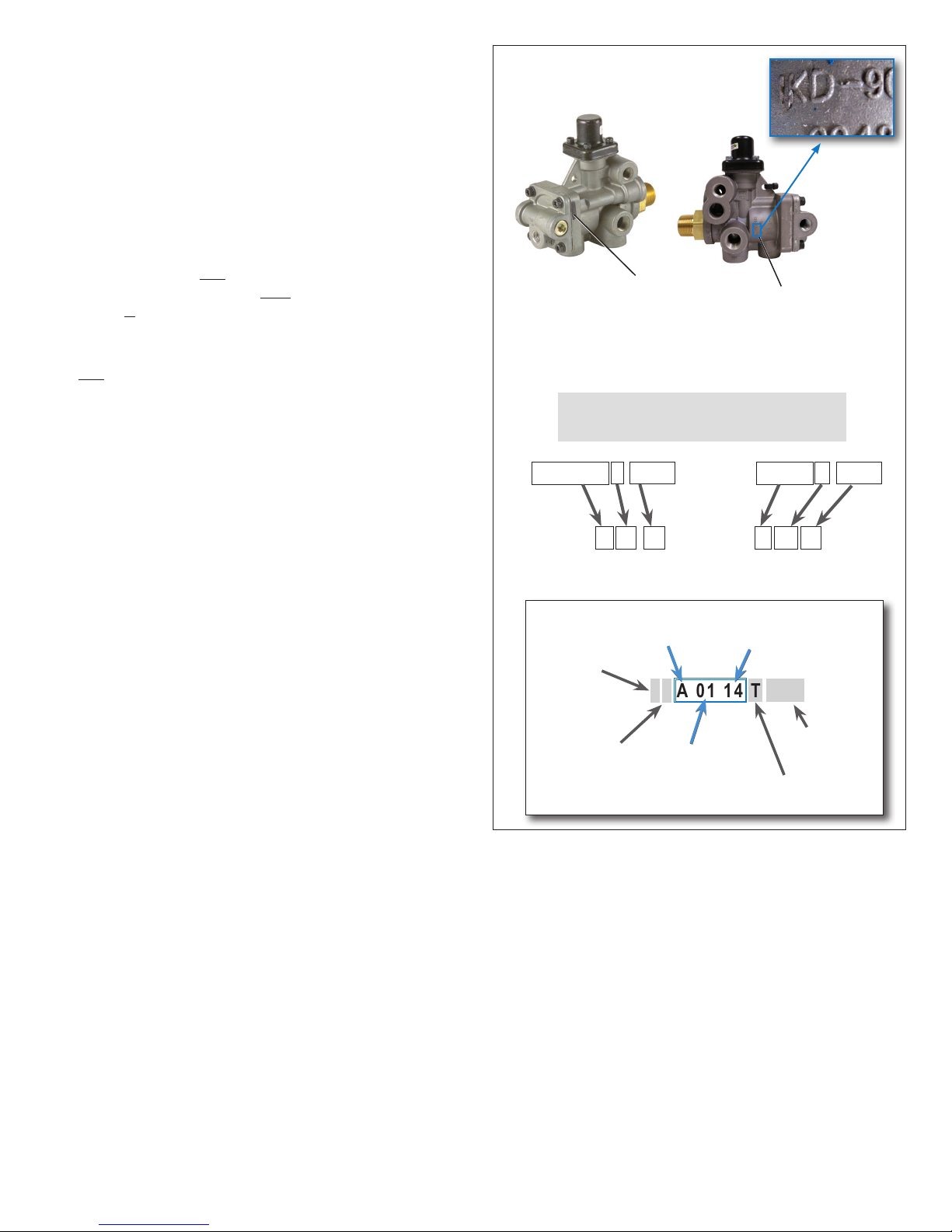
by the supplier code and the date of manufacture located on
the valve body. Verication of both is required to determine if
the valve is a part of the campaign. Valves covered by this
campaign must meet the following criteria:
1. The supplier code – “IKD” – located as shown in Figure 9;
and
2. The date of manufacture between January 1, 2014 and
March 4, 2016, inclusive. To verify the date code see
INTERPRETING THE DATE CODE below.
Date Code
Location
Supplier
Code Location
Bendix SR-5 Valve
Valves included in this eld action were
manufactured during the period:
INTERPRETING THE DATE CODE
A date code is stamped (not cast) on the SR-5 valve body
housing. Locate the date code – removing the paint coating,
if necessary – to read the code. Disregard the Work Team
Number, Shift of Manufacture, Manufacturing Plant and Shift
Serial Number codes shown in gray below. The portion of the
date code that determines the date of manufacture is highlighted
and can be interpreted as follows:
• The rst eld is the month (A = January, B = February, etc.
– excluding the letter I – so that J = September, and so on),
• The next two elds are the day of the month (e.g. 01 = 1st); and
• The next two elds are the year (e.g. 14 = 2014).
January 1, 2014 through March 4, 2016
That is, A 01 14T through C 04 16T
Month – A through M
Skipping I
Work Team
Number
(Optional)
Shift of
Manufacture
(Optional)
_1 A 01 14 T SSS
Day of Month
01 through 31
Figure 9 – Recall Identication
Year
14, 15, or 16
Serial Number
Manufacturing
Shift
(Optional)
Plant
5
Page 6
Visit the online Product Action Center
under the Services and Support tab on
bendix.com. Applicable information on
the recall is available and refreshed often.
On-line training that's available when you are 24/7/365.
S-1655 Rev. 000 © 2016 Bendix Commercial Vehicle Systems LLC, a member of the Knorr-Bremse Group. 08/16 All Rights Reserved.
Log-on and Learn from the Best
Visit www.brake-school.com.
 Loading...