

Page 1

KL2612
2-Channel 125 V AC Relay Output Terminal
Configuration Instructions
Version 1.1
2006-20-23
Page 2
Datasheet for KL2612, Version 1.1
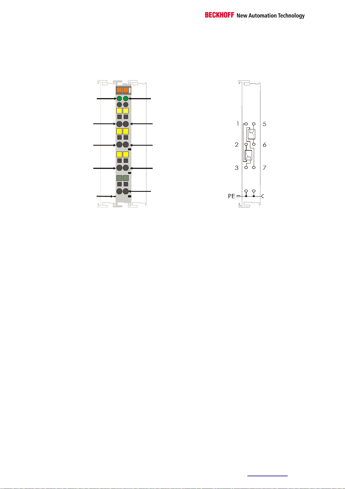
Top view
KL2612
3
7
Introduction KL2612
13
14
A
B
C
D
1
5
Signal LED2
LED display
Process data
OUT
OUT
power
contact
IN
2 6
5
6
OUT
1
2
IN
3
7
OUT
PE
PE
4
8
PE
Functional Description
The KL2612 output terminal switches two relays, each having one
changeover contact, under control of the automation device. The signal
state of the bus terminal is indicated by an LED. If the LED is on, it means
that the contact between 2 and 1 or, in the case of the second relay,
between 6 and 5, is closed. The KL2612 Bus Terminal does not have a
power contact, which means that a voltage that has been passed on
through earlier terminals via the power contacts must be fed in again after
a KL2612.
The signal LEDs indicate the operational state of the associated terminal
channel.
On: Changeover between 2-1 (6-5) closed
Off: Changeover between 2-3 (6-7) closed
Or:
A watchdog timer overflow has occurred. If no process data is handled by
the bus coupler for 100 ms, the green LED goes out and the outputs are
set to 0.
The bit-width in the process image is 2 bits.
Beckhoff™ and TwinCAT are registered trademarks of Beckhoff. Information is subject to change without notice and warranted only to the extent agreed in the terms
of contract. Beckhoff Automation GmbH, Eiserstr. 5, 33415 Verl, Germany, Phone: +49 (0) 5246 963 0, Fax.: +49 (0) 5246 963 149, http://www.beckhoff.com
Page 3

Datasheet for KL2612, Version 1.1
Technical data
Technical data KL2612
Number of outputs
Contact material
Switched voltage max.
Switched current max.
Switched power max.
with resistive load
Minimum permitted load
(approximate)
Reaction times
at rated load
Electrical isolation
K-bus current consumption
Bit width in the process
image
Service life (operating
cycles) mechanical
Operating cycles electr.
(min.)
Permitted operating
frequency at maximum
contact load
Contact resistance max. (new)
2 x change-over
Gold-clad silver alloy
125 V AC / 30 V DC
5 A
alternating voltage
0,5 A 125V AC
direct voltage
2 A 30V DC
10 µA at 10mV
Max. reaction time 4 ms
Max. release time 4 ms
max. bounce time 4 ms
500 V
60 mA
2 A
108 cycles
105 resistive load switches
at 30 V DC, 2 A
or 125 V AC, 0,5 A
20 cycles / min
< 40 mOhm
(K-bus/mains voltage)
eff
Insulation resistance (min).
Test voltage between
open contacts
Configuration
Weight approx.
Operating temperature
Storage temperature
Relative humidity
Vibrations/Shock
resistance
EMC resistance burst / ESD
Installation position
Type of protection
100 MOhm at 500 V DC
750 V (1 min. between open contacts)
No address or configuration settings
80 g
0°C ... +55°C
-25°C ... +85°C
95% without dew formation
according to IEC 68-2-6 / IEC 68-2-27
According to EN 50082 (ESD, burst) / EN 50081
any
IP20
Beckhoff™ and TwinCAT are registered trademarks of Beckhoff. Information is subject to change without notice and warranted only to the extent agreed in the terms
of contract. Beckhoff Automation GmbH, Eiserstr. 5, 33415 Verl, Germany, Phone: +49 (0) 5246 963 0, Fax.: +49 (0) 5246 963 149,
http://www.beckhoff.com
Page 4

Datasheet for KL2612, Version 1.1
i
Note
Smooth operation
Notes on the Correct Use of Relay
Terminals
It is extremely important to observe the technical specifications if fault-free
operation is to be guaranteed. Any time that the stated parameters are
exceeded, damage ranging from premature contact ageing up to fused
contacts can result.
If relays are to be used in a control system the expected operating
conditions must be analysed with great care.
Switching capacity, service life (operating cycles) and the number of
switches per minute must be considered.
Appropriate protective circuits must be used to protect the relay contacts
from excessive voltage peaks such as can occur when switching inductive
loads (contactors, motors etc.). This allows switching frequencies nearly
equal to those appropriate to resistive loads to be achieved. Arcing time
when switching DC loads are significantly longer than those for comparable
AC voltages (where there is a zero-voltage transition); melting of the
material can result.
Warning!
Service life
If the terminal is used to change the direction of inductive loads, adequate
dead-times during the switch-over must be provided, in order to avoid
temporary short-circuits.
It is the maximum values that are to be expected that are critical to
selection of the right terminal rather than the technical figures for normal
operation!
Beckhoff™ and TwinCAT are registered trademarks of Beckhoff. Information is subject to change without notice and warranted only to the extent agreed in the terms
of contract. Beckhoff Automation GmbH, Eiserstr. 5, 33415 Verl, Germany, Phone: +49 (0) 5246 963 0, Fax.: +49 (0) 5246 963 149, http://www.beckhoff.com
 Loading...