

Page 1
Documentation for
KL2521-0000, KL2521-0024
1-Channel Pulse Train Output Terminals, RS422 / 24VDC
Version: 1.8
Date: 2009-05-06
Page 2

Table of contents
Table of contents
1. Foreword 1
Notes on the documentation 1
Safety Instructions 2
2. Product Overview 3
Technical data 3
3. Functional description 4
Introduction 4
Resolution 5
Ramp function 5
Travel distance control 5
Output pattern 6
LED display 6
Connection 7
4. Access from the user program 10
Process Data 10
Register overview 11
Module-specific register description 12
Register communication 13
Control and Status Byte 15
5. Appendix 16
Support and Service 16
KL2521
Page 3

Foreword
Foreword
Notes on the documentation
This description is only intended for the use of trained specialists in control and automation engineering
who are familiar with the applicable national standards. It is essential that the following notes and
explanations are followed when installing and commissioning these components.
Liability Conditions
The responsible staff must ensure that the application or use of the products describe d satisfy all the
requirements for safety, including all the relevant laws, regulations, guidelines and standards.
The documentation has been prepared with care. The products described are, however, constantly under
development. For that reason the documentation is not in every case checked for consistency with
performance data, standards or other characteristics. None of the statements of this manual represent s a
guarantee (Garantie) in the meaning of § 443 BGB of the German Civil Code or a statement about the
contractually expected fitness for a particular purpose in the meaning of § 434 par. 1 sentence 1 BGB. In
the event that it contains technical or editorial errors, we retain the right to make alterations at any time
and without warning. No claims for the modification of products that have already been supplied may be
made on the basis of the data, diagrams and descriptions in this documentation.
Delivery conditions
In addition, the general delivery conditions of the company Beckhoff Automation GmbH apply.
Copyright
©
This documentation is copyrighted. Any reproduction or third party use of this publication, whether in
whole or in part, without the written permission of Beckhoff Automation GmbH, is forbidden.
KL2521 1
Page 4

Foreword
Safety Instructions
State at Delivery
All the components are supplied in particular hardware and software configurations appropriate for the
application. Modifications to hardware or software configurations other than those described in the
documentation are not permitted, and nullify the liability of Beckhoff Automation GmbH.
Description of safety symbols
The following safety symbols are used in this documentation. They are intended to alert the reader to the
associated safety instructions..
Danger
Attention
i
Note
This symbol is intended to highlight risks for the life or health of personnel.
This symbol is intended to highlight risks for equipment, materials or the
environment.
This symbol indicates information that contributes to better understanding.
2 KL2521
Page 5
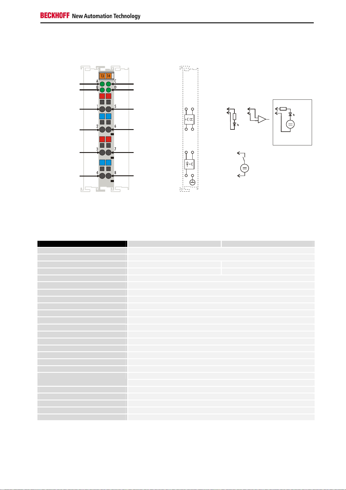
Product Overview
Product Overview
A Signal - LED
B Signal - LED
+A
+B
+T
GND T,Z
Top view
T Signal - LED
Z Signal - LED
- A
- B
+Z
Shield
GND Z,T Shield
+A
+B
- A
- B
+T +Z
Contact Assembly
Technical data
Technical data KL2521-0000 KL2521-0024
Number of outputs
Load type*
Rated load voltage*
Output current
Base frequency
Mark/space ratio
Resolution
Ramp calculation
Output cycle time
Delay time
Number of outputs
Input current
Electrical isolation
Current consumption from K-Bus
Input process image
Output process image
Configuration
Weight
Permissible relative humidity
Vibration / shock resistance
EMC resistance burst / ESD
Installation position
Type of protection
1 channel, 2 differential outputs (A, B)
ohmic, opto-coupler, differential inputs
5 VDC internal 5 V ... 24 VDC external
max. 0.05 A, RS485 specification max. 0.5 A
100 Hz ... 500 kHz, 50 kHz default
50%
16 bits over one word in the fieldbus, 24 bits usable altogether
2 ms / step
1 ms (synchronous to K-Bus)
0.6 ms after K-Bus cycle
2 (+T, +Z)
2.3 to 2.8 mA at 5 V to 30 V
500 V
typ. 75 mA, max. 120 mA (load dependent)
24 bit I (16 bit in data, 8 bit status)
24 bit O (16 bit out data, 8 bit control)
Via the Bus Coupler with KS2000 or the controller
approx. 50 g
0°C ... +55°C (during operation) Permissible ambient temperature
-25°C ... +85° C (during storage)
95%, no condensation
according to EN 60068-2-6 / EN 60068-2-27, EN 60068-2-29
according to EN 61000-6-2 / EN 61000-6-4
any
IP20
(K-Bus / field potential output / input)
eff
*) depends on the hardware version pf the terminal, see chapter Connection
Default Mode Active Mode
RS485
+/- 5V
5…24V
Connection technique
+
5…24V
KL2521 3
Page 6

Functional description
Functional description
process image By default, the KL2521 terminal occupies three bytes in the process image.
operating modes In addition to the FM (frequency modulation) operating mode, the KL2521
default setting The KL2521 is set to FM mode by default, with a basic frequency of 50 kHz
ramp function An internal ramp function raises/lowers the current frequency to the pre-set
Introduction
The KL2521 output terminal generates a binary signal with a variable
frequency. The peripheral side of the electronics is electrically isolated from
the internal K-Bus, and therefore also from the fieldbus. The output
frequency can be adjusted. 16 bit values (signed integer) can be provided
for this adjustment through the controller's process image. These values
modify the output frequency from zero up to a pre-selected maximum
frequency in equal increments - there are 32767 (15 bits) steps in each
direction (right/left).
The mapping of the KL2521 can be set by means of the controller or by the
Bus Coupler's configuration interface using the Beckhoff KS2000
configuration software.
can also be used to control stepper motors with pulse-direction control (frq.
cnt pulse mode). Incremental transducer simulation is another operating
mode. It is possible to connect an incremental transducer directly. Such
inputs are present on many servo amplifiers and frequency converters.
and a resolution of 15 bits. The number of pulses output is read back into a
16 bit register. If the counter overflows a signal is sent to the controller.
This is indicated by Status.3 (overflow) or Status.2 (under flow). In parallel
with these two bits, Status. 6 is set as a general error bit. This makes the
extension to more than 16 bits easier for the controller software to handle.
The overflow can also be read from register 3 (internal 32 bit extension).
The counter can be reset to 0 through Control.5. By default, the counter is
cleared by a rising edge (Feature.4 = 1). If Feature.4 = 0, the function is
level-controlled.
value defined by register R0 (lower word) and register R1 (higher word).
maximum frequency in accordance with the parameters set in registers
40/41. This is activated by FeatureBit.5. The base frequency for the ramp
can be selected by FeatureBit.6. Status.1 is set while a ramp is being
followed.
The releasing of Control.0 can be used to deactivate the function. During
operation this can also be done by Control.1. In this way the user can
change the base frequency during operation very quickly. Setting
Control.0 = 1 (confirmed by Status.0) the values in registers 38/39 are used
instead of those in registers 36/37 (Control.0 = 0).
The input signals T and Z are transferred directly from the terminal to the
controller in the status byte (Status.4 / Status.5). The signals are not given
any internal pre-processing.
If bit Feature.10 = 1, the counter is set by bit Control.5 to a
4 KL2521
Page 7

Functional description
Resolution
The base frequencies are specified with their resolution of 1 Hz per bit
(GF1: registers 36, 37 or GF2: registers 38, 39). The terminal operates
internally at 16 MHz with a resolution of 32 bits. This corresponds to a
theoretical minimum step size of 0.0037 Hz/step over the entire frequency
range. The output stage allows a maximum frequency of 500 kHz to be
output.
Ramp function
The terminal offers a facility for soft starting and stopping. The ramp
gradient for starting can be set in register 40 with a precision of 10 or 1000
Hz/s (Feature.6). Register 41 performs the same function for stopping. The
process data can be modified during transit of the ramp (Status.2), and the
terminal then takes the new value as its target frequency.
Travel distance control
If the "travel distance control" function is active (Feature.9), then a rising
edge at Control.2 will result in drive to a fixed counter value. This value
must previously be entered in register 0 (low word) and in register 1 (high
word) at runtime. Time t
40. t
is reached at the maximum frequency f1 (register 2). Time t3 is
2
is specified by the ramp time constant in register
1
determined by the ramp time constant in register 41 with which the slowing
down frequency f
(register 43) is achieved. When the given counter
2
contents have been reached, the terminal switches the frequency to zero.
In order to travel to a destination with precision, it is necessary that the
time constant for the falling ramp is greater than that of the rising ramp by a
certain factor. This is necessary so that the slowing down frequency is
reached before the final counter state, so that the terminal does not drive
up to the end point at full speed.
To explain in more detail: the KL2521 calculates the number of steps that
are still to be taken in time t
from time t1 and from the number of steps that
2
have been taken. The calculation for stopping assumes the same number
of steps as that found for starting up. The downward ramp must be a little
steeper, approx. 10%, so that it is possible to reach the destination exactly
in the remaining time t
+ t4 + t5. This relationship changes with the
3
maximum frequency.
KL2521 5
Page 8

Functional description
operating modes The pattern of pulses is output through channels A and B. It is possible to
Output pattern
configure the necessary operating mode via feature register R32.
The operating modes differ primarily between the positive logic modes 0, 1
and 2 and the negative logic modes 4, 5 and 6.
Operating modes 2 and 6 simulate an incremental encoder, and permit
direct connection to an evaluation unit such as a servoamplifier or
frequency converter with an incremental encoder input.
Operating mode Function
Rotation to the right Rotation to the left
Frequency modulation
positive logic ( BA 0 )
A
B
Pulse-direction control
positive logic ( BA 1 )
A
B
Incremental encoder
positive logic ( BA 2 )
A
B
Frequency modulation
negative logic ( BA 4 )
Pulse-direction control
negative logic ( BA 5 )
Incremental encoder
negative logic ( BA 6 )
Signal LEDs
watchdog When the watchdog is active (Feature.2 = 0!) the terminal will switch the
LED display
The 4 LEDs illuminate when the input and output signal levels are active.
The illumination of the LEDs for the active frequency outputs A or B at
higher frequencies can only be perceived as a glow at half brightness.
outputs off or will output a value stored in register 35 if no new process
data is transferred to the terminal within 100 ms.
A
B
A
B
A
B
6 KL2521
Page 9

Functional description
Connection
Connection of the inputs
Circuit examples for output to A. The same principles apply to output B.
The optically isolated inputs are protected from overload by a current
limiter. The operating voltage can lie in the range between 5 V ... 24 V
DC
without any additional external circuitry. The GND connection is the
common ground for the two inputs, T and Z.
The circuit diagram shows the internal circuitry of the two inputs:
+T +Z
3 mA
konstant
GND Z,T
Connection of the outputs
Outputs A and B on the KL2521 can be used with different types of
connection. An integrated DC/DC converter supplies the outputs stage of
the two channels, A and B, with an electrically isolated 5 V power supply.
Connection to a RS485/RS232 receiver
The output can be operated as RS485 or as RS232 output. The circuit
generates the necessary differential signals.
+A
- A
KL2521-0000
Connection to an optocoupler (without external power supply)
The outputs can be used for direct connection of an optocoupler. The
output stage supplies the necessary output current using an internal 5 V
power supply.
+A
220R
- A
KL2521-0000
KL2521 7
Page 10

Functional description
i
Note
Check the hardware
version
Connection to an optocoupler (with external power supply)
For connection to inputs with large internal impedances, an external power
supply (of up to 24 V) can be used in order to create the necessary current.
The operation with external power supply depends on the hardware
version of the terminal:
• until hardware version 03 you can use the standard terminal
KL2521-0000 for this.
• from hardware version 04 this is only possible with special terminal
KL2521-0024, that is especially optimized for this application!
But because the KL2521-0024 misses the internal power supply
(5 V), it is not suitable for connection of a RS232/485 receiver or
an optocoupler without external power supply.
The firmware and hardware version (delivery state) can be found in the
serial number printed at the side of the terminal.
Structure of the serial number: WW YY FF HH
WW - week of production (CW, calendar week)
YY - year of production
FF - firmware version
HH - hardware version
Example with ser. no.: 12 06 4F 03:
12 - week of production 12
06 - year of production 2006
4F - firmware version 4F
03 - hardware version 03
Until hardware version 03
+A
4K7
- A
KL2521-0000
7...24V
Instead of hardware version 04 (or higher) use special terminal
KL2521-0024
+A
- A
KL2521-0024
4K7
7...24V
8 KL2521
Page 11

Functional description
KL2521-0024: Connection to external electronics
For connection to external electronics pay attention that KL2521-0024's
terminal points A- of the first and B- of the second channel are internally
connected to each other.
123
A+ B+
A+ B+
AB
A+ B+
KL2521-0024
A- B-
24V
KL2521-0024
A- BAB
KL5151-0000
0V
24V
KL2521-0024
A- BAB
KL5151-0000
0V
24V
This allows two channel connections of external electronics, if the
KL2521-0024 switches the grounds of the external device, as shown in
example 1.
The Beckhoff incremental encoder interface terminals KL5111, KL5121,
i
Note
KL5151 and KL5152 require the switching of the positive voltage.
Because the terminal points A- and B- of KL2521-0024 are internally
bridged, the KL2521-0024 is not able to switch the two inputs of the
KL5151-0000, shown in example 2, independently of each other.
So this red crossed application doesn't make sense!
But you can use one channel of the KL2521-0024 to switch one channel of
the KL5151-0000, as shown in example 3.
KL2521 9
Page 12

Access from the user program
Access from the user program
Input format: Two's complement representation (integer - 1 corresponds to
(relative data)
(direct data) It is possible to enter the frequency directly (Feature.7).
relative data:
Process Data
0xFFFF)
or sign / amount representation (Feature.3) (integer -1 corresponds to
0x8001)
The output frequency is specified within maximum resolution of 15 bits (the
16th bit is used to specify the direction).
Negative process data results in rotation in the opposite direction. In this
case, the internal counter counts to decreasing values.
The output frequency is based on the base frequency that is set in
registers 36 to 39 and the process data (see table).
Output frequency = base frequency x process data / 32767
Highest resolution = 125 mHz
Example:
Base frequency = 100,000 Hz (maximum selected output frequency)
Process data = 0x00FF (255
Output frequency = 778.22 Hz
In this case the process data is multiplied by the factor contained in register
42, and directly written to the synthesis chip.
Output frequency = frequency factor x process data x 10 mHz
Highest resolution = 10 mHz
Example:
Frequency factor = 100
Process data = 0x00FF (255
Output frequency = 255 Hz
Process data Output value
Two's
complement
Sign-amount
0x0000
0x3FFF
0x7FFF
0xC000
0x8000
0xBFFF
0xFFFF
)
dec
)
dec
0% DC
50% of the base frequency, rotation to the right
100% of the base frequency, rotation to the right
50% of the base frequency, rotation to the left
100% of the base frequency, rotation to the left
50% of the base frequency, rotation to the left
100% of the base frequency, rotation to the left
10 KL2521
Page 13

Access from the user program
Register overview
Register set
Address Description Default value R/W Memory medium
R0
R1
R2
R3
R4
...
R7
R8
R9
R10
R11
R12
R13
R14
R15
R16
R17
...
R30
R31
R32
R33
R34
R35
R36*
R37*
R38*
R39*
R40
Target counter state (low word)
Target counter state (high word)
Maximum frequency
Counter extension (high word)
reserved
...
Command register
Terminal type
Firmware version number
Multiplex shift register
Signal channels
Minimum data length
Data structure
reserved
Alignment register
Hardware version number
reserved
...
reserved
Code word register
Feature register
reserved
reserved
User's switch-on value
Base frequency 1 (low word)
Base frequency 1 (high word)
Base frequency 2 (low word)
Base frequency 2 (high word)
Ramp time constant (rising,
0x0000 (0
0x0000 (0
0x0000 (0
0x0000 (0
0x0000 (0
dec
dec
dec
dec
dec
)
)
)
)
)
...
0x0000 (0
dec
)
0x09D9 (2521
0x3446 (4F
0x0118 (280
0x0118 (280
ASCI
dec
dec
0x1818 (6468
0x0004 (4
0x0000 (0
dec
dec
)
)
variable
0x0003 (3
0x0000 (0
dec
dec
)
)
...
0x0000 (0
dec
)
variable
0x0030 (48
0x0000 (0
0x0000 (0
0x0000 (0
dec
dec
dec
dec
)
)
)
0xC350 (50000
0x0000 (0
dec
)
0x86A0 (34464
0x0001 (1
dec
)
0x03E8 (1000
)
dec
)
)
)
)
dec
)
)
dec
)
dec
) R/W
dec
R/W RAM
R/W RAM
R/W RAM
R RAM
R
...
R/W
...
RAM
R ROM
R ROM
R ROM
R ROM
R ROM
R ROM
R
R/W RAM
R/W EEPROM
R/W
...
R/W
...
R/W RAM
R/W EEPROM
R/W
R/W
R/W EEPROM
R/W EEPROM
R/W EEPROM
R/W EEPROM
R/W EEPROM
EEPROM
see feature register)
R41
Ramp time constant (falling,
0x03E8 (1000
) R/W
dec
EEPROM
see feature register)
R42
Frequency factor (direct input,
0x0064 (100
) R/W
dec
EEPROM
(digit x 10 mHz)
R43
Slowing down frequency
0x0032 (50
) R/W
dec
EEPROM
(travel distance control)
...
reserved
...
reserved
0x0000 (0
...
0x0000 (0
) R/W
dec
) R/W
dec
...
...
R44
R61
*) The change of the base frequency needs a reset for activation.
KL2521 11
Page 14

Access from the user program
Module-specific register description
R7: Command register [0x0000]
For a standard command to be executed, it is first necessary for the user
code word, 0x1235, to be entered into
Command 0x7000: Restore Factory Settings
Entering 0x7000 in register R7 restores the factory settings for the
following registers:
R32:
R33:
R34:
R35:
R36:
R37:
0x0030
0x0000
0x0000
0x0000
0xC350
0x0000
(48
(0
(0
(0
(50000
(0
dec
dec
dec
dec
dec
dec
R32: Feature register [0x0030]
The feature register specifies the terminal’s operating mode.
Feature bit no.
Bit 1 – Bit 0
Bit 2
Bit 3
Bit 4
Bit 5
Bit 6
Bit 7
Bit 8
Bit 9
Bit 10
Bit 12 – Bit 11
Bit 15 – Bit 13
pos. logic neg. logic [000] Operating mode Value range
000 100
001 101
010 110
-
0
1
1
1
0/1
0/1
0/1
1
0/1 [0] Counter
-
register R31.
)
)
)
)
)
)
Description of the operating mode
No function
[0] Watchdog timer active
The watchdog timer is switched on by default.
Either the manufacturer's of the user's switch-on
value is output if the watchdog overflows.
[0] Sign / amount representation [0]
Sign / amount representation is active instead of
two's-complement representation. (-1 = 0x8001)
[1] The counter is cleared by a rising edge in the
Counter_Clear bit in the control byte
[1] Ramp function active
[0] Ramp base frequency
0: 10 Hz/s
1: 1000 Hz/s
[0] Input mode
0: relative
1: direct
[0] Behavior when watchdog triggered
0: Manufacturer's switch-on value
1: User's switch-on value
[0] Travel distance control active
0: delete
1: set
No function
Frequency modulation
Pulse-direction control
Incremental encoder
R38:
R39:
R40:
R41:
R42:
R43:
0x86A0
0x0001
0x03E8
0x03E8
0x0064
0x0032
(34464
(1000
(1000
0 – 500 kHz
(1
(100
(50
dec
dec
dec
dec
dec
dec
)
)
)
)
)
)
12 KL2521
Page 15

Access from the user program
Register communication
Register access via
process data transfer
Bit 7=1: register mode
When bit 7 of the control byte is set, the first two bytes of the user data are
not used for process data transfer, but are written into or read out of the
terminal’s register.
Bit 6=0: read
Bit 6=1: write
In bit 6 of the control byte, you define whether a register is to be read or
written. When bit 6 is not set, a register is read without modification. The
value can be taken from the input process image.
When bit 6 is set, the user data is written into a register. The operation is
concluded as soon as the status byte in the input process image has
supplied an acknowledgement (see examples).
Bits 0 to 5: address The address of the register to be addressed is entered in bits 0 to 5 of the
control byte.
Control byte in the register mode
Bit 7 6 5 4 3 2 1 0
Name REG=1 W/R A5 A4 A3 A2 A1 A0
REG = 0: Process data transfer
REG = 1: Access to register structure
W/R = 0: Read register
W/R = 1: Write register
A5...A0 = Register address
A total of 64 registers can be addressed with the addresses A5...A0.
To the bus coupler
K-Bus
Control-/
status byte
C/S-bit 7
If control bit 6=0: read
If control bit 6=1: write
Complex bus te rmina l
The control or status byte occupies the lowest address of a logical channel.
The corresponding register values are located in the following 2 data bytes
(the BK2000 is an exception to the rule: here, an unused data byte is
inserted after the control or status byte, thus setting the register value to a
word limit).
User data
2 or mors bytes
H
L
If contr ol bit 7=0 : input/output
If contr ol bit 7=1 :
registerconfiguration
If control bit 7=1:
adress in the control bit 0-5
Terminal´s
register set
64 words
63
0
H
L
KL2521 13
Page 16

Access from the user program
Examples for Register Communication
Example 1 Reading register 8 in the BK2000 with a Kl3022 and the end terminal.
If the following bytes are transferred from the controller to the terminal,
Byte
Name
Value
Byte3 Byte2 Byte1 Byte0
Data OUT, low byte Data OUT, high byte Not used Control
0xXX 0xXX 0xXX 0x88
the terminal returns the following type designation (0x0BCE corresponds to
the unsigned integer 3022).
Byte
Name
Value
Byte3 Byte2 Byte1 Byte0
Data IN, low byte Data IN, high byte Not used Status
0xCE 0x0B 0x00 0x88
Example 2 Writing register 31 in the BK2000 with an intelligent terminal and the end
terminal.
If the following bytes (user code word) are transferred from the controller to
the terminal,
Byte
Name
Value
Byte3 Byte2 Byte1 Byte0
Data OUT, low byte Data OUT, high byte Not used Control
0x35 0x12 0xXX 0xDF
the user code word is set and the terminal returns the register address with
the bit 7 for register access and the acknowledgement.
Byte
Name
Value
Byte3 Byte2 Byte1 Byte0
Data IN, low byte Data IN, high byte Not used Status
0x00 0x00 0x00 0x9F
14 KL2521
Page 17

Access from the user program
Control and Status Byte
Control Byte in process data exchange
The Control Byte is sent to the terminal from the controller. It can be used
in register mode (REG = 1) or in process data exchange (REG = 0).
Bit 7 6 5 4 3 2 1 0
Name Reg_Access 0 Cnt_Clr 0 0 Go_Counter Ramp_Dis Freq_Sel
Bit Name Function
7 Reg_Access
5 Cnt_Clr
2 Go_Counter
1 Ramp_DisS
0 Freq_Sel
0: Register communication inactive (process data exchange)
The contents of the counter is cleared or set (Feature.10) by this
bit. Any overflow or underflow bits that might be set are also
cleared by this bit. The process can be edge triggered or level
triggered (Feature.4).
If travel distance control is active (Feature.9), then a pre-set
counter value is approached when the bit is set
Operation of the ramp function is cancelled, in spite of Feature.5
being active; if travel distance control is active, it is interrupted by
this bit
Rapid change of the base frequency
(only if the ramp function is inactive)
0: Base frequency 1 (registers 36 / 37)
1: Base frequency 2 (registers 38 / 39)
Status Byte in process data exchange
The Status Byte is sent from the module to the controller.
Bit 7 6 5 4 3 2 1 0
Name Reg_Access Error Input_Z Input_T Overflow Underflow Ramp_Active
Sel_Ack/
End_Counter
Bit Name Function
7 Reg_Access
6 Error
5 Input_Z
4 Input_T
3 Overflow
2 Underflow
1 Ramp_Active
0 Sel_Ack/
End_Counter
0: acknowledge for process data exchange
General error bit, included with overflow/underflow
End position reached
The actual value when the device is connected does not agree
with the set value of the connected device.
This bit is set if the 16-bit counter overflows (65535 -> 0). It is
reset when the counter exceeds one third of its measuring range
(21845 -> 21846) or immediately an underflow occurs.
This bit is set if the 16-bit counter underflows (0 -> 65535). It is
reset when the counter drops below two thirds of its measuring
range (43690 -> 43689) or immediately an overflow occurs.
Ramp is currently being followed
Confirms the change of base frequency.
At activated travel distance control:
target counter value reached
The change of the base frequency needs a reset for activation.
KL2521 15
Page 18

Appendix
Appendix
Support and Service
Beckhoff and their partners around the world offer comprehensive support and service, making available
fast and competent assistance with all questions related to Beckhoff products and system solutions.
Beckhoff Support
Support offers you comprehensive technical assistance, helping you no only with the application of
individual Beckhoff products, but also with other, wide-ranging services:
• world-wide support
• design, programming and commissioning of complex automation systems
• and extensive training program for Beckhoff system components
Hotline: +49(0)5246/963-157
Fax: +49(0)5246/963-9157
e-mail: support@beckhoff.com
Beckhoff Service
The Beckhoff Service Center supports you in all matters of after-sales service:
• on-site service
• repair service
• spare parts service
• hotline service
Hotline: +49(0)5246/963-460
Fax: +49(0)5246/963-479
e-mail: service@beckhoff.com
You will find further support and service addresses on our Internet pages under http://www.beckhoff.com.
Beckhoff Headquaters
Beckhoff Automation GmbH
Eiserstr. 5
33415 Verl
Germany
Phone: +49(0)5246/963-0
Fax: +49(0)5246/963-198
e-mail: info@beckhoff.com
The addresses of Beckhoff 's branch offices and representatives round the world can be found on her
internet pages: http://www.beckhoff.com .
You will also find further documentation for Beckhoff components there.
16 KL2521
 Loading...