

Page 1
Documentation for
KL1501
Up/Down-Counter Terminal, 24 VDC, 100 kHz
Version: 2.2
Date: 2006-10-20
Page 2

Table of Contents
Table of Contents
1 Foreword 1
1.1 Notes on the documentation 1
1.1.1 Liability Conditions 1
1.1.2 Delivery conditions 1
1.1.3 Copyright 1
1.2 Safety Instructions 2
1.2.1 State at Delivery 2
1.2.2 Description of safety symbols 2
2 Product Overview 3
2.1 Technical data 3
2.2 Functional Description 4
3 Terminal configuration 5
3.1 Register Overview 7
3.2 Register description 7
3.2.1 General register description 7
3.2.2 Terminal-specific register description 10
3.3 Control and Status Byte 11
3.4 Register communication with KL1501 12
3.4.1 Examples for Register Communication 13
3.5 Data transfer, function 14
3.5.1 Automatic setting of the outputs with defined counter readings 14
4 Appendix 15
4.1 Mapping in the bus coupler 15
4.2 Support and Service 17
4.2.1 BECKHOFF Support 17
4.2.2 BECKHOFF Service 17
4.2.3 BECKHOFF company headquarters 17
KL1501
Page 3

Foreword
1 Foreword
1.1 Notes on the documentation
This description is only intended for the use of trained specialists in control and automation engineering
who are familiar with the applicable national standards. It is essential that the following notes and
explanations are followed when installing and commissioning these components.
1.1.1 Liability Conditions
The responsible staff must ensure that the application or use of the products described satisfy all the
requirements for safety, including all the relevant laws, regulations, guidelines and standards.
The documentation has been prepared with care. The products described are, however, constantly under
development. For that reason the documentation is not in every case checked for consistency with
performance data, standards or other characteristics. None of the statements of this manual represents a
guarantee (Garantie) in the meaning of § 443 BGB of the German Civil Code or a statement about the
contractually expected fitness for a particular purpose in the meaning of § 434 par. 1 sentence 1 BGB. In
the event that it contains technical or editorial errors, we retain the right to make alterations at any time
and without warning. No claims for the modification of products that have already been supplied may be
made on the basis of the data, diagrams and descriptions in this documentation.
1.1.2 Delivery conditions
In addition, the general delivery conditions of the company Beckhoff Automation GmbH apply.
1.1.3 Copyright
©
This documentation is copyrighted. Any reproduction or third party use of this publication, whether in
whole or in part, without the written permission of Beckhoff Automation GmbH, is forbidden.
KL1501 1
Page 4
Foreword
i
1.2 Safety Instructions
1.2.1 State at Delivery
All the components are supplied in particular hardware and software configurations appropriate for the
application. Modifications to hardware or software configurations other than those described in the
documentation are not permitted, and nullify the liability of Beckhoff Automation GmbH.
1.2.2
The following safety symbols are used in this documentation. They are intended to alert the reader to the
associated safety instructions..
Description of safety symbols
This symbol is intended to highlight risks for the life or health of personnel.
Danger
This symbol is intended to highlight risks for equipment, materials or the
Attention
Note
environment.
This symbol indicates information that contributes to better understanding.
2 KL1501
Page 5
Product Overview
2 Product Overview
Product name KL1501
Number of counters
Rated load voltage
‘0’ signal voltage
‘1’ signal voltage
Switching frequency
Input current
Current consumption from K-Bus
Counter depth
Electrical isolation
Bit width in the process image
Configuration
Weight approx.
Operating temperature
Storage temperature
Relative humidity
Vibration / Shock resistance
EMC resistance burst / ESD
Installation position
Type of protection
2.1 Technical data
1 or 2
24 VDC (20 V ... 29 V)
-3 V ... 5 V
15 V ... 30 V
100 kHz (2 kHz by switching U/D)
typical 5 mA.
typical 50 mA
32 bit or 2 x 16 bit
500 Vrms (K-Bus / field voltage)
40 I/O: 32 bits data, 8 bits control/status
no address settings, configurations via bus coupler or control system
50 g
0°C ... +55°C
-25°C ... +85°C
95%, no condensation
conforms to EN 60068-2-6 / EN 60068-2-27, EN 60068-2-29
conforms to EN 61000-6-2 / EN 61000-6-4
any
IP20
KL1501 3
Page 6

Product Overview
2.2 Functional Description
The input terminal KL1501 counts binary pulses and transmits the current
value to the higher-level control system. In addition to the 32-bit up/down
counter, a 32 bit gated counter or two 16 bit counters are available as
operating modes. In the gated counter mode, a low level or high level at
the gate input suppresses the terminal’s counting function. If two 16 bit
counters are active, the U/D input is the clock input for the second counter.
Two digital outputs can also be set.
The maximum input frequency is limited to 100 kHz. The minimum pulse
width of the input signal is approximately 1 microsecond. The counters
react to the rising edge of the input signal.
Via the control byte, from the control system the counter status can be set,
the terminal’s counting function can be suppressed and the outputs can be
activated. An internal function can also be activated to enable automatic
setting of the outputs at defined counter statuses.
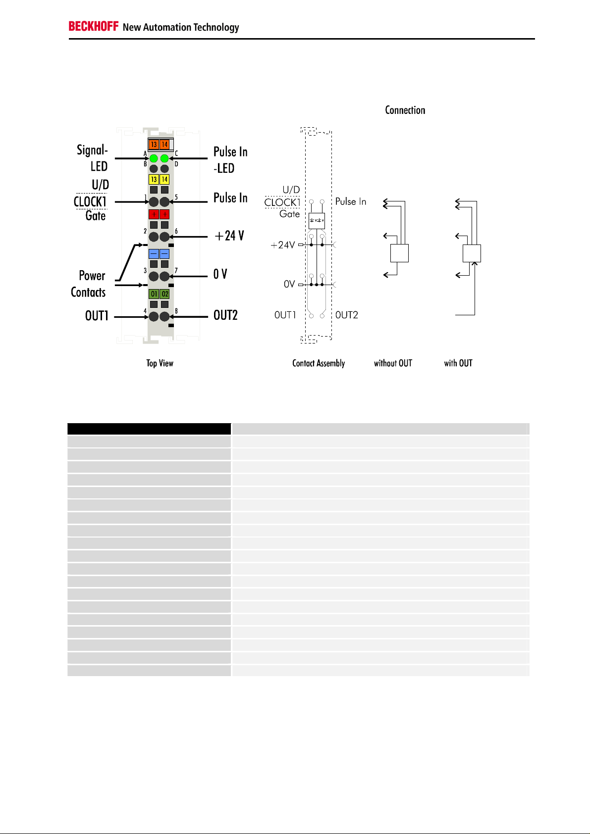
LED display The LEDs indicate the states of the U/D and CLOCK inputs as well as the
states of the outputs OUT1 and OUT2.
Process data
Standard output format
When using the standard output format, 5 bytes (4 bytes of user
information data and 1 control/status byte) are mapped. The process data
differs depending on the set function:
• Gated counter:
32 bit unsigned integer
• Up/down counter:
32 bit signed integer
• Two active counters:
2 x 16 bit unsigned integer
Mapping of the terminal in the standard format is described in further detail
in the appendix.
Alternative output format If the alternative output format is chosen, pay attention to the fact that the
output length (4 bytes or 6 bytes instead of 5 bytes) and mapping of the
terminal are changed.
• Up/down counter:
24 bit signed integer
• Gated counter:
24 bit signed integer
• Two active counters:
1 x 8 bit counter0 and 1 x 16-bit counter1
4 KL1501
Page 7
Terminal configuration
i
Offset Terminal1= 0
Offset Terminal2 Channel1= 3
Offset Terminal2 Channel2= 5
Offset Terminal3 Channel1 = 7
User data allocation depending
To the bus terminal
Offset Termina1= 0
Offset Terminal2 Channel1 = 5
Offset Terminal2 Channel2 = 8
To the bus terminal
3 Terminal configuration
The terminal can be configured and parameterized by way of the internal
Note
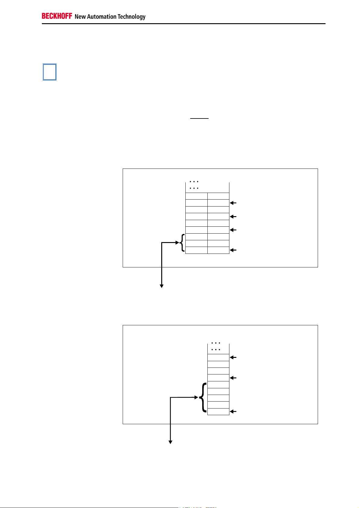
Contrary to the analog and output terminals, in the case of the KL1501 the
Lightbus coupler BK2000 In the case of the Lightbus coupler BK2000, the control /status byte is
register structure. Each terminal channel is mapped in the bus coupler. The
terminal’s data is mapped differently in the bus coupler’s memory
depending on the type of the bus coupler and on the set mapping
configuration (e.g. Motorola/Intel format, word alignment etc.).
control and status byte is always also mapped, regardless of the field bus
system used.
always mapped besides the data bytes. It is always in the low byte at the
offset address of the terminal channel.
Beckhoff-Lightbus
bus coupler
BK2000
The terminal is
mapped in the
bus coupler
Data H
Data H
Data LH
D3
D1
0
Data L
C/S
Data L
C/S
Data L
C/S
D2
D0
C/S
on mapping
KL1501
LH
K-Bus
Profibus coupler BK3000 When using the Profibus coupler BK3000, the KL1501 is automatically
mapped with 5 bytes of input data and 5 bytes of output data.
Profibus bus coupler
BK3000
The terminal is
mapped in the
bus coupler.
0
C/S
Data H
Data L
C/S
D0
D1
D2
D3
C/S
The control/status byte
must be inserted for
parameterization.
The control/status byte
will be inserted for
parameterization (KL1501).
KL1501 5
K-Bus
Page 8

Terminal configuration
Offset Termina1= 0
Offset Terminal2 Channel1 = 5
Offset Terminal2 Channel2 = 8
To the bus terminal
i
Interbus Coupler BK4000 By default, the Interbus coupler BK4000 maps the KL1501 with 5 bytes of
input data and 5 bytes of output data.
Interbus bus coupler
BK4000
The terminal is
mapped in the
bus coupler.
0
C/S
Data H
Data L
C/S
D0
D1
D2
D3
C/S
The control/status byte
must be inserted for
parameterization (KS2000).
The control/status byte
will be inserted for
parameterization (KL1501).
K-Bus
Other bus couplers and
further information
Note
Parameterization with the
KS2000 software
You will find further information on the mapping configuration of bus
couplers in the annex of the respective bus coupler manual under the
heading of Configuration of masters.
In the appendix it exists an outline of the possible mapping configurations
in dependency of the adjustable parameters.
Using the KS2000 configuration software, the parameterization operations
can be carried out independently of the field bus system via the bus
couplers serial interface.
6 KL1501
Page 9

Terminal configuration
3.1 Register Overview
Register No. Description Default R/W Storage medium
R0
not used 0x0000 R
...
... ... ... ...
R5
not used 0x0000 R
R6
Diagnostic register – not used 0x0000 R
R7
Command register - not used 0x0000 R
R8
Terminal type 1501 R ROM
R9
Software version number 0x???? R ROM
R10
R11
R12
R13
R14
R15
R16
R17
R30
R31
R32
R33
R63
Multiplex-shift register 0x0130 R ROM
Signal channels 0x0128 R ROM
minimum data length 0x2828 R ROM
Data structure 0x0000 R ROM
not used 0x0000 R
Alignment-register variable R/W RAM
Hardware version number 0x???? R/W SEEROM
not used 0x0000 R/W SEEROM
...
... ... ... ...
not used 0x0000 R/W SEEROM
Code word register variable R/W RAM
Feature register 0x0100 R/W SEEROM
not used 0x0000 R/W SEEROM
...
... ... ... ...
not used 0x0000 R/W SEEROM
3.2 Register description
The complex terminals can be adjusted to different operating modes or
functionalities. The General Description of Register describes the contents
of the registers, which are identical for all complex terminals.
The terminal-specific registers are explained in the section following to it.
The access to the internal registers of the terminal is described in the
section Register Communication.
3.2.1 General register description
Complex terminals that possess a processor are capable of bidirectionally
ex-changing data with the higher-level control system. Below, these
terminals are referred to as intelligent bus terminals. They include the
analog inputs, the analog outputs, serial interface terminals (RS485,
RS232, TTY etc.), counter terminals, encoder interfaces, SSI interfaces,
PWM terminals and all other parameterizable terminals.
Internally, all intelligent terminals possess a data structure that is identical
in terms of it's essential characteristics. This data area is organized in
words and embraces 64 registers. The essential data and parameters of
the terminal can be read and adjusted by way of the structure. Function
calls with corresponding parameters are also possible. Each logical
channel of an intelligent terminal has such a structure (therefore, 4-channel
analog terminals have 4 register sets.
KL1501 7
Page 10

Terminal configuration
This structure is broken down into the following areas:
Register Application
0 to 7
8 to 15
16 to 30
31 to 47
48 to 63
Process variables
Type register
Manufacturer parameters
User parameters
Extended user area
Process variables
R0 to R7: Registers in the terminal’s internal RAM
The process variables can be used in additional to the actual process
image and their functions are specific to the terminal.
R0 to R5: Terminal specific registers
The function of these registers depends on the respective terminal type
(see terminal-specific register description).
R6: Diagnostic register
The diagnostic register may contain additional diagnostic information. In
the case of serial interface terminals, for example, parity errors that have
occurred during data transfer are indicated.
R7: Command register
High-Byte_Write = function parameter
Low-Byte_Write = function number
High-Byte_Read = function result
Low-Byte_Read = function number
Type registers
R8 to R15: Registers in the terminal’s internal ROM
The type and system parameters are programmed permanently by the
manufacturer and can only be read by the user but cannot be modified.
R8: Terminal type:
The terminal type in register R8 is needed to identify the terminal.
R9: Firmware version X.y
The firmware version can be read as an ASCII character string.
3.2.1.1 R10: Data length
R10 contains the number of multiplexed shift registers and their length in
bits.
The bus coupler sees this structure.
R11: Signal channels
In comparison with R10, the number of logically existing channels is
located here. For example, one physically existing shift register may
consist of several signal channels.
R12: Minimum data length
The respective byte contains the minimum data length of a channel to be
transferred. If the MSB is set, then the control/status byte is not necessarily
needed for the function of the terminal and, with appropriate configuration
of the coupler, is not transferred to the control system.
8 KL1501
Page 11
Terminal configuration
i
R13: Data type register
Data type register
0x00
0x01
0x02
0x03
0x04
0x05
0x06
0x07
0x08
0x11
0x12
0x13
0x14
0x15
0x16
Terminal without valid data type
Byte array
1 byte n bytes structure
Word array
1 byte n words structure
Double word array
1 byte n double words structure
1 byte 1 double word structure
1 byte 1 double word structure
Byte-array with a variable logical channel length
1 byte n bytes structure with a variable logical channel
length (eg 60xx)
Word-array with a variable logical channel length
1 byte n words structure with a variable logical channel
length
Double word array with a variable logical channel length
1 byte n double words structure with a variable logical
channel length
R14: not used
R15: Alignment bits (RAM)
The analog terminal is set to a byte limit in the terminal bus with the
alignment bits.
Manufacturer parameters
R16 to R30: Manufacturer parameter area (SEEROM)
The manufacturer parameters are specific to each terminal type. They are
programmed by the manufacturer but can also be modified from the control
system. The manufacturer parameters are stored permanently in a serial
EEPROM and are therefore not destroyed by power failures.
These registers can only be modified after setting a code word in R31.
User parameters
R31 to R47: User parameter area (SEEROM)
The user parameters are specific to each terminal type. They can be
modified by the programmer. The user parameters are stored permanently
in a serial EEPROM in the terminal and cannot be destroyed by power
failures. The user area is write protected over a Codeword.
R31: Code word register in the RAM
Note
The code word 0x1235 must be entered here to enable modification of
parameters in the user area. Write-protection is set if a different value is
entered in this register. When write protection is inactive, the code word is
returned during reading of the register. The register contains the value zero
when write protection is active.
R32: Feature-register
This register defines the operating modes of the terminal. For example, a
user-specific scaling can be activated for the analog I/Os.
R33 to R47
Registers that depend on the terminal type
Extended application area
R47 to R63
These registers have not yet been implemented.
KL1501 9
Page 12

Terminal configuration
3.2.2 Terminal-specific register description
R32: Feature register
[0x0100]
The feature register specifies the operating modes of the terminal.
Feature bit no. Description of the mode
Bit 0
Bit 1
Bit 2
Bit 3
Bit 4
Bit 5
Bit 6
Bit 7
Bit 10, 9, 8
Bit 11
Bit 12
Bit 15, 14, 13
- No function
0/1 Output format
0: Standard output [0]
1: Alternative output
1 If two counters are active, the CNT_INH bit
becomes CNT_SET for the second counter [0].
1 The counter(s) is/are set with a positive edge of the
CNT_SET bit in the control byte [0]
1 The internal function for setting output OUT1 is
active [0].
1 The internal function for resetting output OUT1 is
active [0].
1 The internal function for setting output OUT2 is
active [0].
1 The internal function for resetting output OUT2 is
active [0].
001 32-bit up/down counter [001].
24-bit if alternative output format is active.
010 Standard output: 2 *16-bit up counter
Alternative output: counter0 is 8 bits and couner1 is
16 bits wide
The counting frequency is limited to approximately 5
kHz.
[Pulse width > 100 microseconds]
100 32-bit gated counter
24-bit if alternative output format is active
gate input low: counter is disabled
101 32-bit gated counter
24-bit if alternative output is active
gate input high: counter is disabled
0/1 Counting direction
0: Up [0]
1: Down
1 Terminal bus access is polled if the bit is set [0]
- No function [0], don't change
10 KL1501
Page 13

Terminal configuration
3.3 Control and Status Byte
The control byte is transmitted from the controller to the terminal. It can be
used
- in register mode (REG = 1
- during process data exchange (REG = 0
bin
) or
bin
).
Control byte during process data exchange
The control byte triggers various actions in the counter terminal KL1501
during process data exchange:
MSB
REG=0 0 CNT_SET CNT_INH SET_OUT2 SET_OUT1 EN_OUT2 EN_OUT1
Bit Function
CNT_SET
CNT_INH
SET_OUT2
SET_OUT1
EN_OUT2
EN_OUT1
The counter is set to the value that is specified via the process
data. Setting of the counter can be edge or level-controlled
(see R32.3).
The counter is stopped as long as this bit is active. In doing so,
the old counter status is retained.
If two counters are active, the second counter can be set with
this bit.
Sets the second output
Sets the first output
This bit enables the internal function activated by R32.
This bit enables the internal function activated by R32.
Setting the outputs
OUT1, OUT2
The functions for setting the outputs can be armed with the control bits
EN_OUT1, EN_OUT2. The control bits SET_OUT1 and SET_OUT2 are
ignored when EN_OUT1, EN_OUT2 is set.
Status byte during process data exchange
The status byte is transferred from the terminal to the control system. The
status byte contains various status bits of the counter terminal KL1501:
MSB
REG=0 0 SET_ACC INH_ACC ST_OUT2 ST_OUT1 ST_V/R ST_CLK
Bit Function
SET_ACC
INH_ACC
ST_OUT2
ST_OUT1
ST_V/R
ST_CLK
The data for setting the counter has been accepted from the
terminal.
The counter is stropped for as long as this bit is set.
The status of output OUT2 is reflected in this bit.
The status of output OUT1 is reflected in this bit.
The status of the V/R input is reflected in this bit.
The status of the CLOCK input is reflected in this bit.
KL1501 11
Page 14
Terminal configuration
0
63
Terminal´s
HHL
L
3.4 Register communication with KL1501
Register access via
process data transfer
Bit 7=1: register mode
When bit 7 of the control byte is set, the first two bytes of the user data are
not used for process data transfer, but are written into or read out of the
terminal’s register.
Bit 6=0: read
Bit 6=1: write
In bit 6 of the control byte, you define whether a register is to be read or
written. When bit 6 is not set, a register is read without modification. The
value can be taken from the input process image.
When bit 6 is set, the user data is written into a register. The operation is
concluded as soon as the status byte in the input process image has
supplied an acknowledgement (see examples).
Bits 0 to 5: address The address of the register to be addressed is entered in bits 0 to 5 of the
control byte.
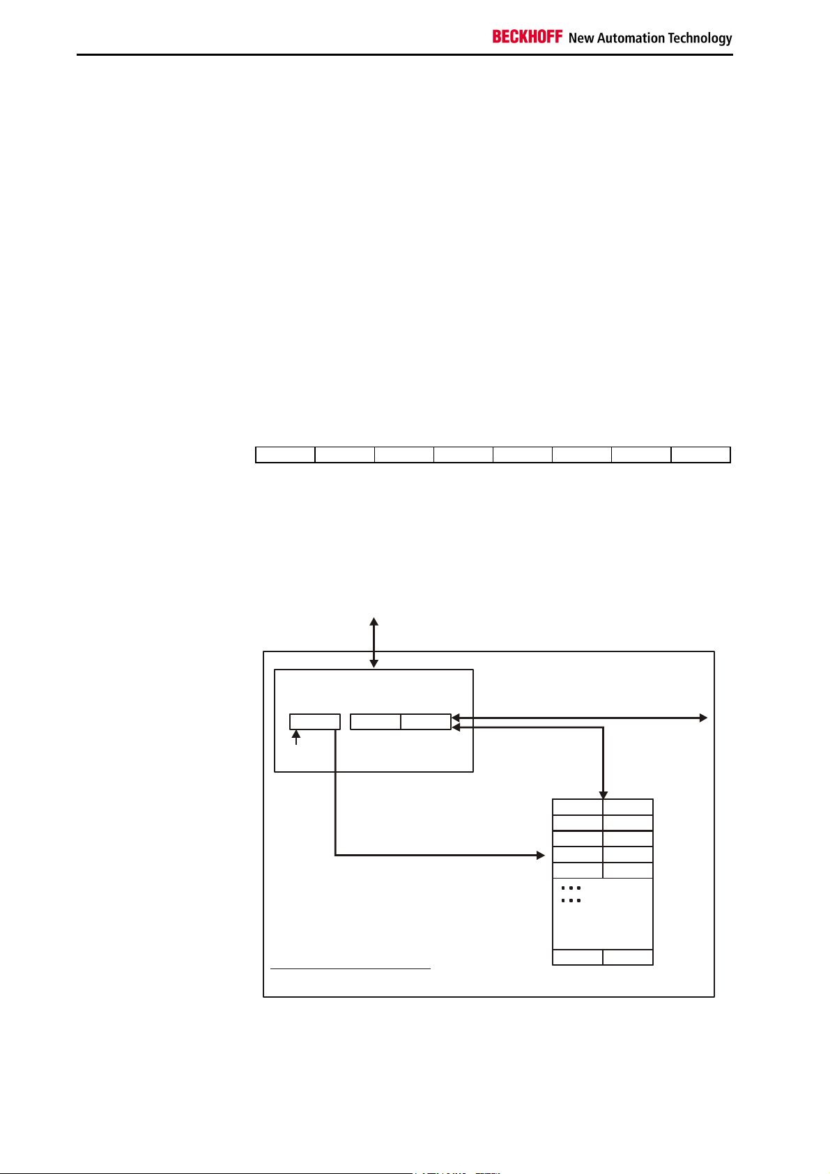
Control byte in the register mode
MSB
REG=1 W/R
A5
A4
A3
A2
A1
A0
REG = 0 : Process data transfer
REG = 1 : Access to register structure
W/R = 0 : Read register
W/R = 1 : Write register
A5..A0 = Register address
A total of 64 registers can be addressed with the addresses A5....A0.
To the bus coupler
K-Bus
Control-/
status byte
C/S-bit 7
If control bit 6=0: read
If control bit 6=1: write
User data
2 or mors bytes
If control bit 7=0: input/output
If control bit 7=1:
registerconfiguration
If control bit 7=1:
adress in the control bit 0-5
register set
64 words
Complex bus terminal
The control or status byte occupies the lowest address of a logical channel.
The corresponding register values are located in the following 2 data bytes
(the BK2000 is an exception to the rule: here, an unused data byte is
inserted after the control or status byte, thus setting the register value to a
word limit).
12 KL1501
Page 15
Terminal configuration
3.4.1 Examples for Register Communication
Example 1 Reading register 8 in the BK2000 with a Kl3022 and the end terminal.
If the following bytes are transferred from the controller to the terminal,
Byte
Name
Value
Byte3 Byte2 Byte1 Byte0
Data OUT, low byte Data OUT, high byte Not used Control
0xXX 0xXX 0xXX 0x88
the terminal returns the following type designation (0x0BCE corresponds to
the unsigned integer 3022).
Byte
Name
Value
Byte3 Byte2 Byte1 Byte0
Data IN, low byte Data IN, high byte Not used Status
0xCE 0x0B 0x00 0x88
Example 2 Writing register 31 in the BK2000 with an intelligent terminal and the end
terminal.
If the following bytes (user code word) are transferred from the controller to
the terminal,
Byte
Name
Value
Byte3 Byte2 Byte1 Byte0
Data OUT, low byte Data OUT, high byte Not used Control
0x35 0x12 0xXX 0xDF
the user code word is set and the terminal returns the register address with
the bit 7 for register access and the acknowledgement.
Byte
Name
Value
Byte3 Byte2 Byte1 Byte0
Data IN, low byte Data IN, high byte Not used Status
0x00 0x00 0x00 0x9F
KL1501 13
Page 16

Terminal configuration
3.5 Data transfer, function
3.5.1 Automatic setting of the outputs with defined
counter readings
V/R counter or gated
counter:
Two counters active: If the corresponding counter reaches the counter status 0x8000 the output
Example Feature register = 0x02AC, i.e. two counters are active, the counter is set
First counter Control
0x0000
0x0000
0x31Ex
0x8000
0x8000
0x31Ex
0x8000
An internal function for setting the outputs can activated via the feature
register R32.
If the counter reaches the counter status 0x80000000 the output OUT1 is
set (feature bit 5) or is reset (feature bit 6).
If the counter overflows, the output is withdrawn accordingly.
In parallel, output OUT2 is set with bit 15 (0x8000).
(OUT2, OUT1) is set (feature bit 4,6) or is reset (feature bit 5,7).
If the counter overflows, the output is withdrawn accordingly.
via the positive edge of the CNT_SET bits and the control bit CNT_INH is
responsible for setting the second counter.
A glass is to be filled with 200 ml of beer. In doing so, one pulse
corresponds to 0.01 ml, i.e. one glass corresponds to 20000 pulses
(0x31E0 = 0x8000-20000).
Status
byte
0x00 0x00 0x0000 Low Power on reset
0x22 0x00 0x31E0 Low Counter is set, internal
0x02 0x28 Don’t care High Beer is running
....
0x02 0x00 Don’t care Low The first glass is full
...
0x22 0x00 0x31E0 Low Counter is set, internal
0x02 0x28 Don’t care High Beer is running
....
0x02 0x00 Don’t care Low The second glass is full
....
byte
Output
data
Output
OUT1
Function
function activated
function activated
14 KL1501
Page 17

Appendix
4 Appendix
As already described in the chapter terminal configuration, each bus
terminal is mapped in the bus coupler. In the standard case, this mapping
is done with the default setting in the bus coupler / bus terminal. This
default setting can be modified with the KS2000 configuration software or
using master configuration software (e.g. ComProfibus or TwinCAT System
Manager). The following tables provide information on how the KL1501
maps itself in the bus coupler depending on the set parameters.
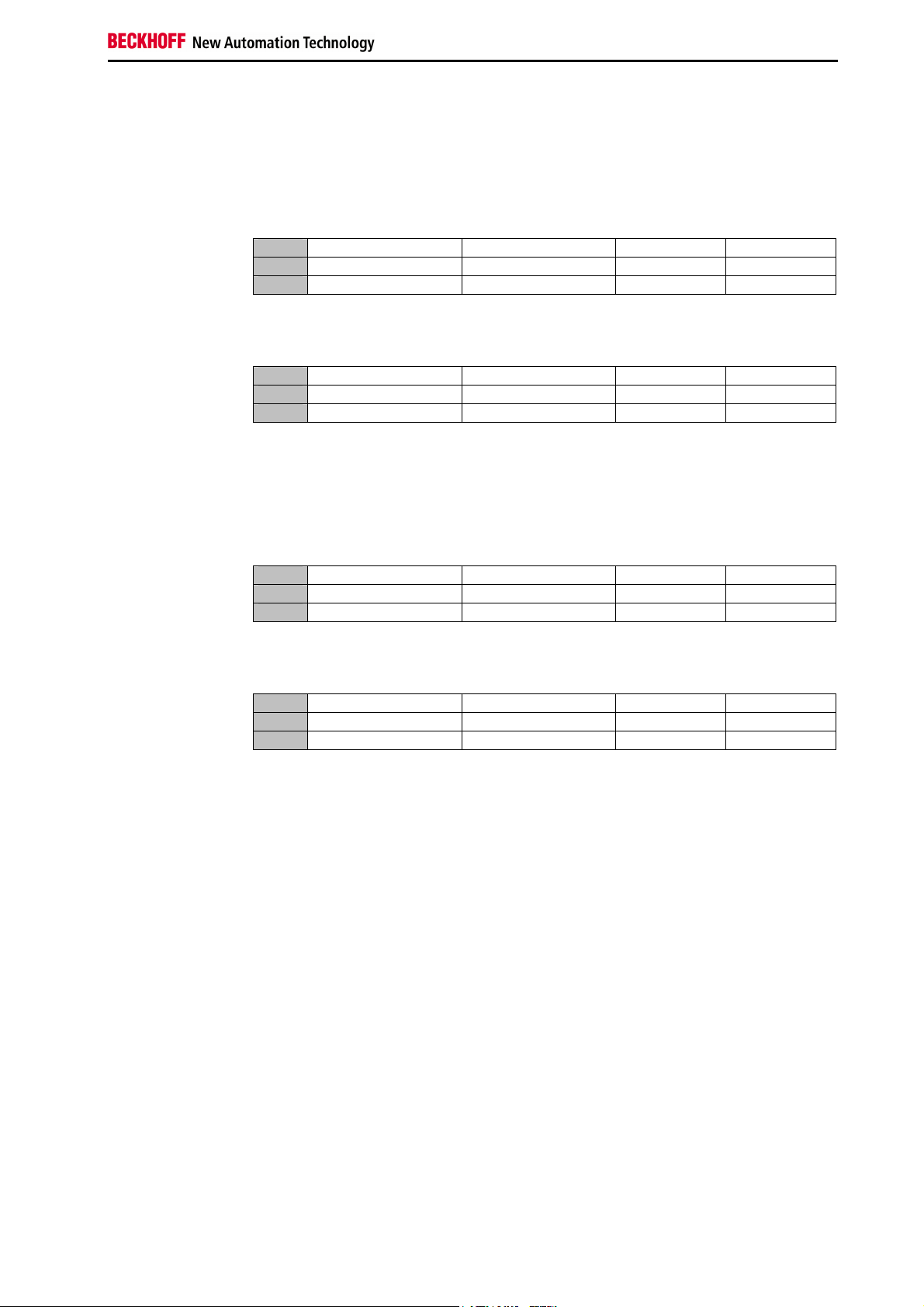
Standard Format In the Standard format the KL1501 is mapped in the bus coupler with 5
Default Mapping for CAN,
DeviceNet, ControlNet,
Modbus, RS232 and
RS485 Coupler
Default-Mapping for
Profibus and Interbus
Coupler
Default-Mapping for
Lightbus and Ethernet
Coupler and
Bus Terminal Controller
(BCxxxx, BXxxxx)
4.1 Mapping in the bus coupler
bytes input and 5 bytes output data.
Conditions Word offset High Byte Low Byte
Complete evaluation: don’t care
Motorola format: no
Word alignment: no
Conditions Word offset High Byte Low Byte
Complete evaluation: don’t care
Motorola format: yes
Word alignment: no
Conditions Word offset High Byte Low Byte
Complete evaluation: don’t care
Motorola format: no
Word alignment: yes
Conditions Word offset High Byte Low Byte
Complete evaluation: don’t care
Motorola format: yes
Word alignment: yes
0 D0 CB/SB
1 D2 D1
2 res. D3
0 D3 CB/SB
1 D1 D2
2 res. D0
0 res. CB/SB
1 D1 D0
2 D3 D2
0 res. CB/SB
1 D2 D3
2 D0 D1
KL1501 15
Page 18

Appendix
Alternative Format In the Alternative format the KL1501 is mapped in the bus coupler with 4/6
bytes input and 4/6 bytes output data.
Conditions Word offset High Byte Low Byte
Complete evaluation: no
Motorola format: no
Word alignment: no
0 D0 Cnt-CB/SB
1 D2 D1
Conditions Word offset High Byte Low Byte
Complete evaluation: no
Motorola format: yes
Word alignment: no
0 Cnt-CB/SB
1 D1 D2
D0
Conditions Word offset High Byte Low Byte
Complete evaluation: yes
Motorola format: no
Word alignment: no
0 Cnt-CB/SB CB/SB
1 res. D0
2 D2 D1
Conditions Word offset High Byte Low Byte
Complete evaluation: yes
Motorola format: yes
Word alignment: no
0 D0 CB/SB
1 res. Cnt-CB/SB
2 D1 D2
Conditions Word offset High Byte Low Byte
Complete evaluation: yes
Motorola format: no
Word alignment: yes
0 res. CB/SB
1 D0 Cnt-CB/SB
2 res. res.
3 D2 D1
Conditions Word offset High Byte Low Byte
Complete evaluation: yes
Motorola format: no
Word alignment: yes
0 res. CB/SB
1 Cnt-CB/SB
D0
2 res. res.
3 D1 D2
Key Complete evaluation:
the terminal is mapped with control / status byte.
Motorola format:
The Motorola or Intel format can be set.
Word alignment:
The terminal is at a word limit in the bus coupler.
CB: Control Byte (appears in the process image of the outputs).
SB: Status Byte (appears in the process image of the inputs).
Cnt-CB: Control Byte in process data exchange
Cnt-SB: Status Byte in process data exchange
res.: reserved:
This byte occupies process data memory, although it is not used.
16 KL1501
Page 19

Appendix
4.2 Support and Service
BECKHOFF and their partners around the world offer comprehensive service
and support, making available fast and competent assistance with all
questions related to BECKHOFF products and system solutions.
4.2.1 BECKHOFF Support
Support offers you comprehensive technical assistance, helping you not
only with the application of individual BECKHOFF products, but also with
other, wide-ranging services:
• world-wide support
• design, programming and commissioning of complex automation
systems
• and extensive training program for BECKHOFF system components
Hotline:
Fax:
e-mail:
4.2.2 BECKHOFF Service
The BECKHOFF Service Centre supports you in all matters of after-sales
service:
Hotline:
Fax:
e-mail:
You will find further support and service addresses on our Internet pages
under: http://www.beckhoff.com.
4.2.3 BECKHOFF company headquarters
BECKHOFF Automation GmbH
Eiserstr. 5
D-33415 Verl
Germany
Phone:
Fax:
e-mail:
The addresses of BECKHOFF's branch offices and representatives round the
world can be found on the internet pages: http://www.beckhoff.com
You will also find further documentation for BECKHOFF components there.
+49(0)5246/963-157
• on-site service
• repair service
• spare parts service
• hotline service
+49(0)5246/963-9157
support@beckhoff.com
+49(0)5246/963-460
+49(0)5246/963-479
service@beckhoff.com
+49(0)5246/963-0
+49(0)5246/963-198
info@beckhoff.com
KL1501 17
 Loading...