

Page 1
Manual | EN
CX20x0
Embedded PC
11/25/2020 | Version: 2.5
Page 2

Page 3

Table of contents
Table of contents
1 Notes on the documentation ....................................................................................................................7
1.1 Representation and structure of warnings.........................................................................................8
1.2 Related documents............................................................................................................................9
1.3 Documentation issue status ..............................................................................................................9
2 For your safety.........................................................................................................................................10
2.1 Intended use....................................................................................................................................10
2.2 Staff qualification .............................................................................................................................10
2.3 Safety instructions ...........................................................................................................................11
3 Transport and storage.............................................................................................................................12
4 Product overview.....................................................................................................................................13
4.1 Configuration of the basic CPU module ..........................................................................................15
4.2 Name plate ......................................................................................................................................16
4.3 Module overview..............................................................................................................................17
4.4 Types...............................................................................................................................................18
4.5 Architekture overview ......................................................................................................................19
5 Description of the interfaces ..................................................................................................................21
5.1 USB (X100, X101, X102, X103) ......................................................................................................21
5.2 Ethernet RJ45 (X000, X001) ...........................................................................................................22
5.3 DVI-I (X200).....................................................................................................................................23
5.4 Optional interfaces...........................................................................................................................24
5.4.1 DVI-D (N010) ................................................................................................................... 24
5.4.2 DisplayPort (N011) .......................................................................................................... 25
5.4.3 RS232 (N030).................................................................................................................. 26
5.4.4 RS422/RS485 (N031)...................................................................................................... 27
5.4.5 EtherCAT slave (B110).................................................................................................... 28
5.4.6 PROFIBUS (x310) ........................................................................................................... 29
5.4.7 CANopen (x510) .............................................................................................................. 30
5.4.8 PROFINET RT (x930)...................................................................................................... 31
6 Commissioning........................................................................................................................................32
6.1 Selecting the appropriate CX2100 power supply unit......................................................................32
6.2 Mounting..........................................................................................................................................33
6.2.1 Attaching the power supply unit....................................................................................... 33
6.2.2 Installing the bar clips ...................................................................................................... 33
6.2.3 Note the permissible installation positions ...................................................................... 34
6.2.4 Attaching on mounting rail ............................................................................................... 36
6.2.5 CFast card installation and removal ................................................................................ 37
6.2.6 Installing passive EtherCAT Terminals............................................................................ 38
6.3 Connecting the power supply ..........................................................................................................39
6.4 Observe the UL requirements .........................................................................................................41
6.5 Switching on ....................................................................................................................................42
6.6 Switching off ....................................................................................................................................42
7 Configuration ...........................................................................................................................................43
7.1 Windows Embedded Compact 7 .....................................................................................................43
CX20x0 3Version: 2.5
Page 4

Table of contents
7.1.1 Scan for new hardware.................................................................................................... 43
7.2 Windows Embedded Standard 7 P..................................................................................................44
7.2.1 Identification of the Ethernet interfaces (X000, X001) ..................................................... 44
7.2.2 Enabling jumbo frames .................................................................................................... 45
7.2.3 Set NIC Teaming ............................................................................................................. 46
7.2.4 Restoring the Beckhoff real-time driver. .......................................................................... 48
7.3 Windows 10 IoT Enterprise LTSB ...................................................................................................49
7.3.1 Identification of the Ethernet interfaces (X000, X001) ..................................................... 49
7.4 Beckhoff Device Manager ...............................................................................................................50
7.4.1 Starting the Beckhoff Device Manager ............................................................................ 50
7.4.2 Enabling a remote display ............................................................................................... 51
7.4.3 Starting a remote connection........................................................................................... 52
7.5 TwinCAT..........................................................................................................................................53
7.5.1 Tree view ......................................................................................................................... 53
7.5.2 Searching for target systems ........................................................................................... 54
7.5.3 Scanning an Embedded PC ............................................................................................ 56
7.5.4 Configuring EtherCAT cable redundancy. ....................................................................... 57
7.5.5 Using a hardware watchdog ............................................................................................ 60
8 NOVRAM...................................................................................................................................................61
8.1 Use under TwinCAT 3 .....................................................................................................................62
8.1.1 Creating a Retain Handler ............................................................................................... 62
8.1.2 Creating and linking variables.......................................................................................... 64
8.1.3 Note the write speed of the Retain Handler..................................................................... 66
8.1.4 Deleting variables under the Retain Handler ................................................................... 67
9 UPS (persistent data) ..............................................................................................................................68
9.1 Windows write filter..........................................................................................................................69
9.2 Checking the validity of the variables ..............................................................................................70
9.2.1 SYSTEMINFOTYPE ........................................................................................................ 70
10 Error handling and diagnostics..............................................................................................................72
10.1 Basic CPU module ..........................................................................................................................72
10.1.1 LEDs on the basic CPU module ...................................................................................... 72
10.1.2 Power supply terminal LEDs in K-bus mode ................................................................... 72
10.1.3 Power supply terminal LEDs in E-bus mode ................................................................... 75
10.2 Faults...............................................................................................................................................76
11 Care and maintenance ...........................................................................................................................77
11.1 Replace the battery .........................................................................................................................77
11.2 Replace the fan cartridge ................................................................................................................78
12 Decommissioning....................................................................................................................................80
12.1 Removing cables .............................................................................................................................80
12.2 Dismantling the Embedded PC .......................................................................................................81
13 Technical data..........................................................................................................................................83
14 Appendix ..................................................................................................................................................85
14.1 Accessories .....................................................................................................................................85
14.2 Certifications....................................................................................................................................86
CX20x04 Version: 2.5
Page 5

Table of contents
14.3 Support and Service ........................................................................................................................87
List of tables.............................................................................................................................................88
List of figures...........................................................................................................................................90
CX20x0 5Version: 2.5
Page 6

Table of contents
CX20x06 Version: 2.5
Page 7

Notes on the documentation
1 Notes on the documentation
This description is only intended for the use of trained specialists in control and automation engineering who
are familiar with applicable national standards.
It is essential that the documentation and the following notes and explanations are followed when installing
and commissioning the components.
It is the duty of the technical personnel to use the documentation published at the respective time of each
installation and commissioning.
The responsible staff must ensure that the application or use of the products described satisfy all the
requirements for safety, including all the relevant laws, regulations, guidelines and standards.
Disclaimer
The documentation has been prepared with care. The products described are, however, constantly under
development.
We reserve the right to revise and change the documentation at any time and without prior announcement.
No claims for the modification of products that have already been supplied may be made on the basis of the
data, diagrams and descriptions in this documentation.
Trademarks
Beckhoff®, TwinCAT®, EtherCAT®, EtherCAT G®, EtherCAT G10®, EtherCAT P®, Safety over EtherCAT®,
TwinSAFE®, XFC®, XTS® and XPlanar® are registered trademarks of and licensed by Beckhoff Automation
GmbH.
Other designations used in this publication may be trademarks whose use by third parties for their own
purposes could violate the rights of the owners.
Patent Pending
The EtherCAT Technology is covered, including but not limited to the following patent applications and
patents:
EP1590927, EP1789857, EP1456722, EP2137893, DE102015105702
with corresponding applications or registrations in various other countries.
EtherCAT® is a registered trademark and patented technology, licensed by Beckhoff Automation GmbH,
Germany
Copyright
© Beckhoff Automation GmbH & Co. KG, Germany.
The reproduction, distribution and utilization of this document as well as the communication of its contents to
others without express authorization are prohibited.
Offenders will be held liable for the payment of damages. All rights reserved in the event of the grant of a
patent, utility model or design.
CX20x0 7Version: 2.5
Page 8

Notes on the documentation
1.1 Representation and structure of warnings
The following warnings are used in the documentation. Read and follow the warnings.
Warnings relating to personal injury:
DANGER
Hazard with high risk of death or serious injury.
WARNING
Hazard with medium risk of death or serious injury.
CAUTION
There is a low-risk hazard that can result in minor injury.
Warnings relating to damage to property or the environment:
NOTE
There is a potential hazard to the environment and equipment.
Notes showing further information or tips:
This notice provides important information that will be of assistance in dealing with the product or
software. There is no immediate danger to product, people or environment.
CX20x08 Version: 2.5
Page 9

Notes on the documentation
1.2 Related documents
This documentation considers and describes material that is relevant for the Embedded-PC CX20x0. The
Embedded-PC CX20x0 is part of a modular system and belongs to the CX2000 Embedded PC series.
Further information on the devices of the CX2000 Embedded PC series can be found in the associated
documentation. Read and follow in particular the sections on safety in this documentation.
The following important documentation can be viewed at and downloaded from the Beckhoff website:
http://www.beckhoff.de
Document name
CX2100-00x4 power supply unit for CX20x0
CX2100-09x4 UPS power supply unit for CX20x0
Retaining the documentation
This documentation is part of the Embedded-PC. Keep the documentation in the immediate vicinity of the
battery pack throughout its entire service life. Ensure that personnel have access to the documentation at all
times. Pass on the documentation to subsequent users, and in addition ensure that all supplementary
information is included in the documentation.
1.3 Documentation issue status
Version Changes
1.0 First Version
1.1 Notes on power connections added, order numbers
for CX20x0-N031 added
1.2 New types added
1.3 UL requirements added
1.4 Chapter “DVI-D port” and “module overview” added.
1.5 Chapter “Types” reworked.
1.6 Chapter “NOVRAM” and “USV (persistent data)”
added.
1.7 Documentation restructured and revised.
1.8 Chapter „Using a hardware watchdog“ added.
1.9 Chapter Beckhoff Device Manager revised
2.0 Chapter “Observe the UL requirements” added.
2.1 Chapter ”Selecting the appropriate CX2100 power
supply unit“ und ”Technical data“ revised.
2.2 Chapter "Types" and "Device Manager" revised.
2.3 Chapter “TwinCAT” revised.
2.4 Chapter “Commissioning” revised.
2.5 Integrated CFast cards adapted from 4 GB and 8 GB
to 20 GB and 40 GB
CX20x0 9Version: 2.5
Page 10

For your safety
2 For your safety
Read the chapter on safety and follow the instructions in order to protect from personal injury and damage to
equipment.
Limitation of liability
All the components are supplied in particular hardware and software configurations appropriate for the
application. Unauthorized modifications and changes to the hardware or software configuration, which go
beyond the documented options, are prohibited and nullify the liability of Beckhoff Automation GmbH & Co.
KG.
In addition, the following actions are excluded from the liability of Beckhoff Automation GmbH & Co. KG:
• Failure to comply with this documentation.
• Improper use.
• Use of untrained personnel.
• Use of unauthorized replacement parts.
2.1 Intended use
The CX2000 Embedded PC series is a modular control system, which is intended for installation on a DIN
rail. The system is scalable, so that the basic PC modules, power supply units, system modules and
extension modules can be assembled and installed in the control cabinet or terminal box as required.
The CX2000 Embedded PC series is used in conjunction with Bus Terminals for recording digital and analog
signals from sensors and transferring them to actuators or higher-level controllers. The CX2000 Embedded
PC series combines the worlds of Industrial PC and hardware PLC and is suitable for control tasks.
The Embedded PC is designed for a working environment that meets the requirements of protection class
IP20. This involves finger protection and protection against solid foreign objects up to 12.5 mm, but not
protection against water. Operation of the devices in wet and dusty environments is not permitted, unless
specified otherwise. The specified limits for electrical and technical data must be adhered to.
Improper use
The Embedded PC is not suitable for operation in the following areas:
• Potentially explosive atmospheres.
• Areas with an aggressive environment, e.g. aggressive gases or chemicals.
• Living areas. If the devices are to be used in living areas, the relevant standards and guidelines for
interference emissions must be adhered to, and the devices must be installed in housings or control
boxes with suitable shielding.
2.2 Staff qualification
All operations involving Beckhoff software and hardware may only be carried out by qualified personnel with
knowledge of control and automation engineering. The qualified personnel must have knowledge of the
administration of the Industrial PC and the associated network.
All interventions must be carried out with knowledge of control programming, and the qualified personnel
must be familiar with the current standards and guidelines for the automation environment.
CX20x010 Version: 2.5
Page 11

For your safety
2.3 Safety instructions
The following safety instructions must be followed during installation and working with networks and the
software.
Mounting
• Never work on live equipment. Always switch off the power supply for the device before installation,
troubleshooting or maintenance. Protect the device against unintentional switching on.
• Observe the relevant accident prevention regulations for your machine (e.g. the BGV A 3, electrical
systems and equipment).
• Ensure standard-compliant connection and avoid risks to personnel. Ensure that data and supply
cables are laid in a standard-compliant manner and ensure correct pin assignment.
• Observe the relevant EMC guidelines for your application.
• Avoid polarity reversal of the data and supply cables, as this may cause damage to the equipment.
• The devices contain electronic components, which may be destroyed by electrostatic discharge when
touched. Observe the safety precautions against electrostatic discharge according to DIN EN
61340-5-1/-3.
Working with networks
• Restrict access to all devices to an authorized circle of persons.
• Change the default passwords to reduce the risk of unauthorized access. Regularly change the
passwords.
• Protect the devices with a firewall.
• Apply the IT security precautions according to IEC 62443, in order to limit access to and control of
devices and networks.
Working with the software
• Use up-to-date security software. The safe function of the PC can be compromised by malicious
software such as viruses or Trojans.
• The sensitivity of a PC against malicious software increases with the number of installed and active
software.
• Uninstall or disable unnecessary software.
Further information about the safe handling of networks and software can be found in the Beckhoff
Information System:
http://infosys.beckhoff.de
Document name
Documentation about IPC Security
CX20x0 11Version: 2.5
Page 12

Transport and storage
3 Transport and storage
Transport
NOTE
Short circuit due to moisture
Moisture can form during transport in cold weather or in the event of large temperature fluctuations.
Avoid moisture formation (condensation) in the Embedded PC, and leave it to adjust to room temperature
slowly. If condensation has occurred, wait at least 12 hours before switching on the Embedded PC.
Despite the robust design of the unit, the components are sensitive to strong vibrations and impacts. During
transport the Embedded PC must be protected from
• mechanical stress and
• use the original packaging.
Table1: Dimensions and weight of the individual modules.
CX2020 CX2030 CX2040
Dimensions (W x H x D) 144 mm x 99 mm x 91 mm
Weight approx. 1160 g approx. 1165 g approx. 1230 g
Storage
• The battery should be removed if the Embedded PC is stored at temperatures above 60°C. The
battery should be stored separate from the Embedded PC in a dry environment at a temperature
between 0 °C and 30 °C.
The preset date and time are lost if the battery is removed.
• Store the Embedded PC in the original packaging.
CX20x012 Version: 2.5
Page 13
Product overview
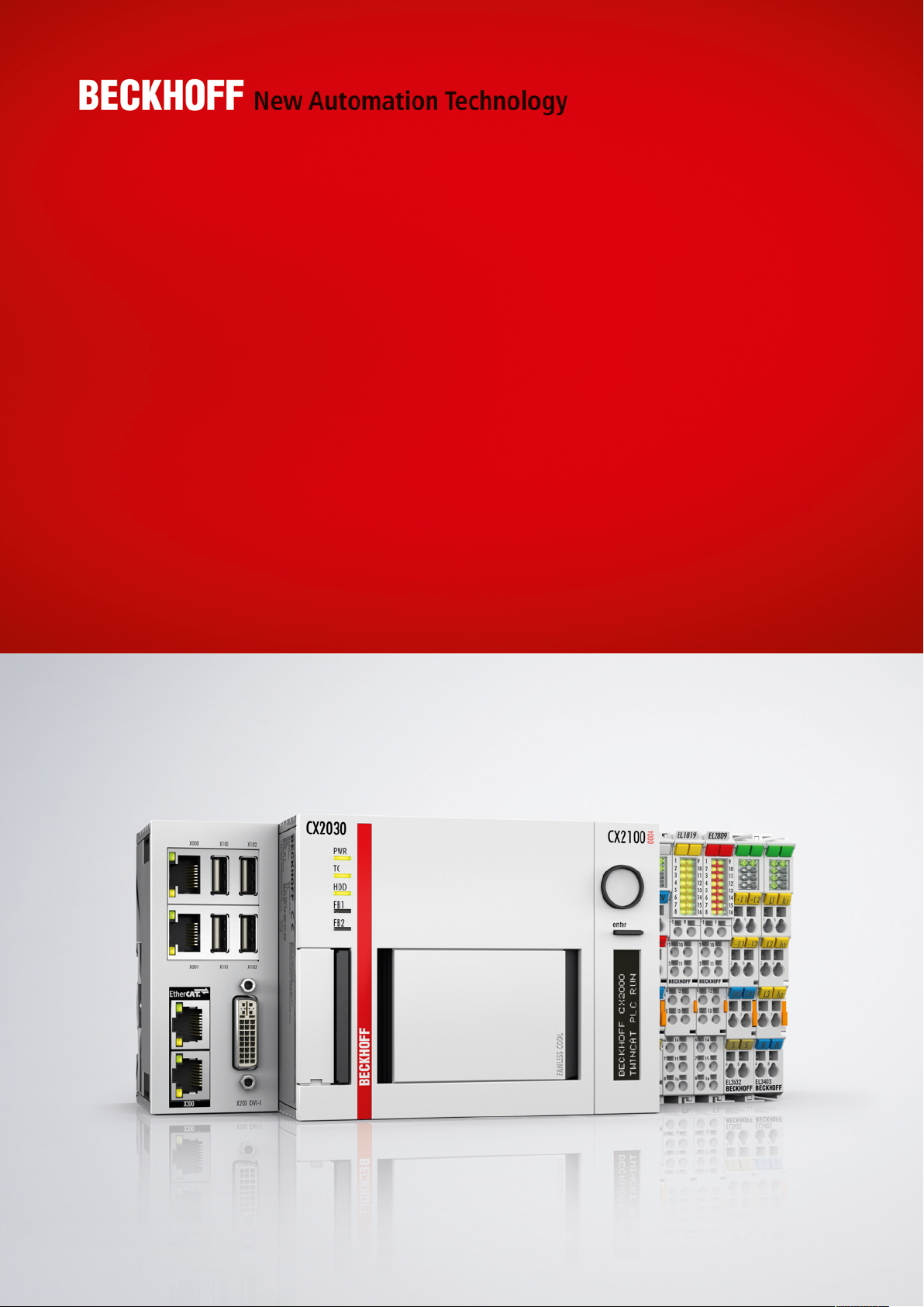
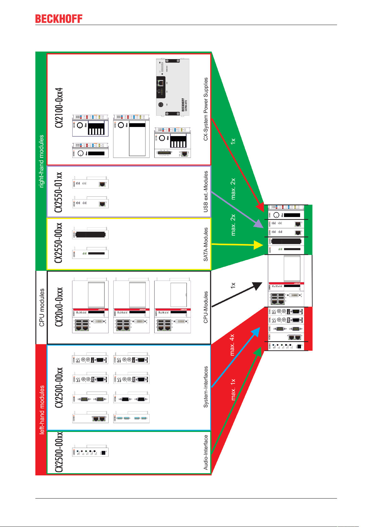
4 Product overview
The CX2000 product family consists of individual modules, which can be assembled to form a customized
Embedded PC.
The CX2000 product family consists of:
• basic CPU modules,
• CX2100 power supply units,
• system, fieldbus and extension modules,
• and the CX2900 battery pack.
Fig.1: Overview of the CX2000 product family with basic CPU module, power supply unit and modules.
Basic CPU module
The basic CPU module is a fully functional PC and can be used in conjunction with a CX2100 power supply
unit as the smallest possible configuration. The basic configuration of the CX2000 Embedded PC includes:
• a CFast card slot,
• two independent Gbit Ethernet interfaces,
• four USB 2.0 interfaces,
• and a DVI-I interface.
The basic CPU module can be extended with additional interfaces or storage media, as required. Up to four
system or fieldbus modules can be connected on the left-hand side of the basic CPU module. Up to four
extension modules can be connected on the right-hand side between the basic CPU module and the power
supply unit. Two extension modules for additional storage media (CFast card, SSD) and two extension
modules for a USB extension.
Suitable operating systems are Microsoft Windows 10 IoT Enterprise LTSB, Microsoft Windows Embedded
Standard 7 P or Microsoft Windows Embedded Compact 7.
The basic CPU module features 128 kB NOVRAM as internal persistent data memory and can be used as
an alternative to a power supply unit with capacitive UPS or an external battery pack. In the event of a power
failure, important data are stored in the NOVRAM and are available again after a restart.
The basic CPU module can be ordered ex factory with an optional interface. The optional interface cannot be
retrofitted.
CX20x0 13Version: 2.5
Page 14

Product overview
Table2: Available optional interfaces for the CX20x0.
CX20x0-xxxx Optional interfaces
CX20x0-N010 DVI-D, additional DVI-D socket for clone and extended display mode.
CX20x0-N011 DisplayPort, additional DisplayPort for clone and extended display mode
CX20x0-N030 RS232, D-sub connector, 9-pin.
CX20x0-N031 RS422/RS485, D-sub socket, 9-pin.
CX20x0-B110 EtherCAT slave, EtherCAT IN and OUT (2 x RJ45).
CX20x0-M310 PROFIBUS master, D-sub socket, 9-pin.
CX20x0-B310 PROFIBUS slave, D-sub socket, 9-pin.
CX20x0-M510 CANopen master, D-sub connector, 9-pin.
CX20x0-B510 CANopen slave, D-sub connector, 9-pin.
CX20x0-M930 PROFINET RT, controller, Ethernet (2 x RJ-45).
CX20x0-B930 PROFINET RT, device, Ethernet (2 x RJ-45 switch).
CX2100 power supply units
The CX2100 power supply units serve the basic CPU module and all additional modules. Bus Terminals (Kbus) or EtherCAT Terminals (E-bus) can be attached on the right-hand side of the power supply units. The
power supply units are available in four different versions:
• CX2100-0004: E-bus/K-bus power supply unit with automatic switchover.
• CX2100-0014: E-bus/K-bus power supply unit with automatic switchover and passive ventilation.
• CX2100-0904: E-bus/K-bus power supply unit with automatic switchover and integrated capacitive
UPS.
• CX2100-0914: E-bus/K-bus power supply unit with automatic switchover and integrated electronic
charging unit for an external battery pack.
All power supply units feature an illuminated anti-glare LC display with two rows of 16 characters each for
displaying status messages. Application-specific texts can be displayed with the aid of user programs.
System, fieldbus and extension modules
System or fieldbus modules of type CX2500-xxxx can be connected on the left-hand side of the basic CPU
module. Up to four modules can be connected to the multi-pin connection on the left. Extension modules of
type CX2550 can be connected on the right between the basic CPU module and the power supply unit.
CX2900 battery pack
The battery pack is a charge store for the CX2000 product family and used as UPS in conjunction with the
CX2100-0914 power supply unit. In the event of a power failure the battery pack supplies the basic CPU
module and further devices (e.g. a Panel) via the CX2100-0914 power supply unit.
Software
In combination with the TwinCAT automation software, the CX20x0 Embedded PC becomes a powerful IEC
61131-3 PLC with up to four user tasks. In conjunction with EtherCAT and TwinCAT, it is possible to
implement very fast control processes in the microsecond range (XFC eXtreme Fast Control Technology).
It is also possible to execute Motion Control tasks with potentially up to 256 axes. Depending on the required
sampling time, several servo axes can be controlled. Even special functions such as flying saw, electronic
gearbox and cam plate can be realized.
In addition to handling real-time control tasks the TwinCAT real-time kernel leaves enough time for the user
interface (HMI). The high performance of the graphics core integrated in the CPU enables demanding
visualizations with advanced user interfaces to be realized.
CX20x014 Version: 2.5
Page 15
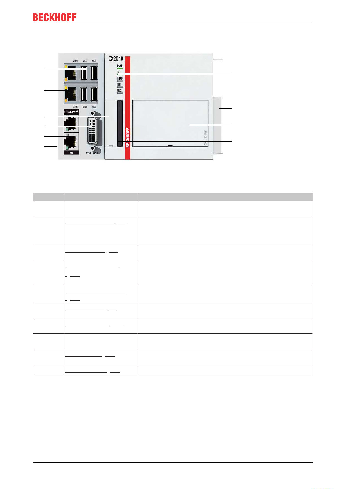
4.1 Configuration of the basic CPU module
1
2
3
6
4
5
7
8
9
10
Fig.2: Example: Embedded PCs CX2040 with active cooling.
Table3: Legend for the configuration of the basic CPU module
Product overview
No. Component Description
1 Multi-pin connection (left) Extension through system modules and fieldbus modules of type
CX2500.
2
3
4
5
6
7
8 Multi-pin connection (right) Connection for extension modules of type CX2550 and for power
9
10
Optional interface [}24]
(X300).
DVI-I interface [}23]
(X200).
Battery compartment
[}77] (under the front
flap).
RJ45 Ethernet interfaces
[}22] (X000, X001).
USB interfaces [}21]
(X100, X101, X102, X103).
Diagnostic LEDs. [}72]
Fan cartridge [}78] (under
the front flap).
CFast card slot. [}37]
Space for interfaces such as RS232, EtherCAT, CANopen or
others.
The optional interface must be ordered ex factory and cannot be
retrofitted retrospectively.
Interface for a monitor or Panel.
Power supply for the battery-backed clock for time and date.
For connecting to local networks, internet or EtherCAT.
Interfaces for peripherals such as mouse, keyboard or USB
memory.
Diagnostic LEDs for power supply, TwinCAT, CFast card and
optional interface.
supply units of type CX2100.
The fan cartridge is provided as standard for the CX2040. The
CX2020 and CX2030 can be ordered with active cooling ex factory.
Slot for industrial CFast cards.
CX20x0 15Version: 2.5
Page 16
Product overview
1
2
3
6
4
5
7
8
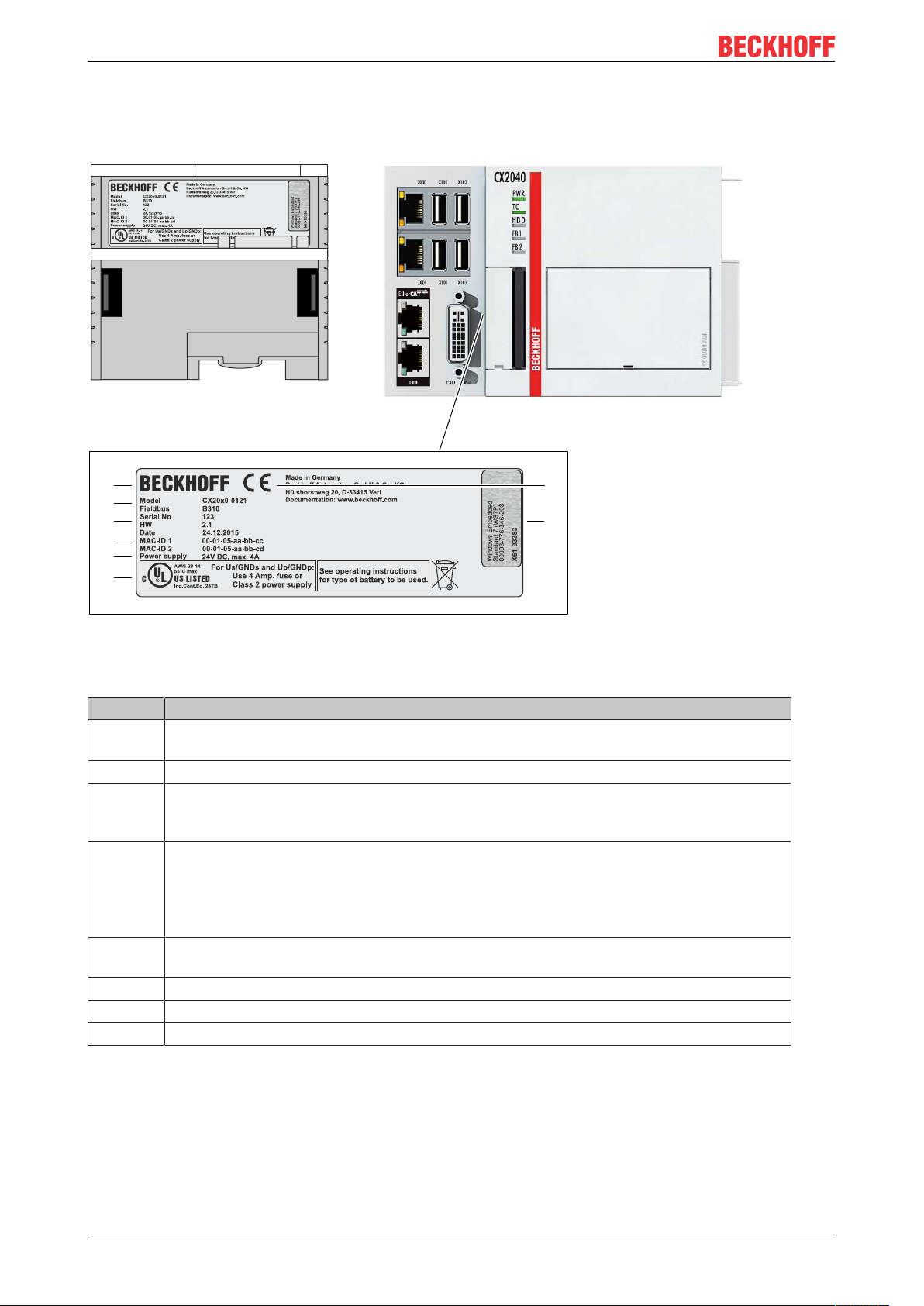
4.2 Name plate
The CX20x0 Embedded PC features a name plate on the left-hand side of the housing.
Fig.3: CX20x0 name plate.
Table4: Legend for the name plate.
No. Description
1 UL approval with prescribed information on power supply, fuse, temperature and cable
cross-sections.
2 Information on the power supply unit. 24 V DC, 4 A max.
3 MAC addresses of the integrated Ethernet ports.
By default, the host name is formed from "CX-" plus the last 3 bytes of the MAC address:
Example: the host name CX-aabbcc is formed from the MAC address 00-01-05-aa-bb-cc.
4 Information on:
• serial number,
• hardware version
• and date of manufacture.
5 Information on the model. The last four numerals relate to the configuration of Embedded
PC.
6 Manufacturer information including address.
7 CE compliant.
8 Windows license sticker (optional).
CX20x016 Version: 2.5
Page 17
4.3 Module overview
Product overview
CX20x0 17Version: 2.5
Page 18
Product overview
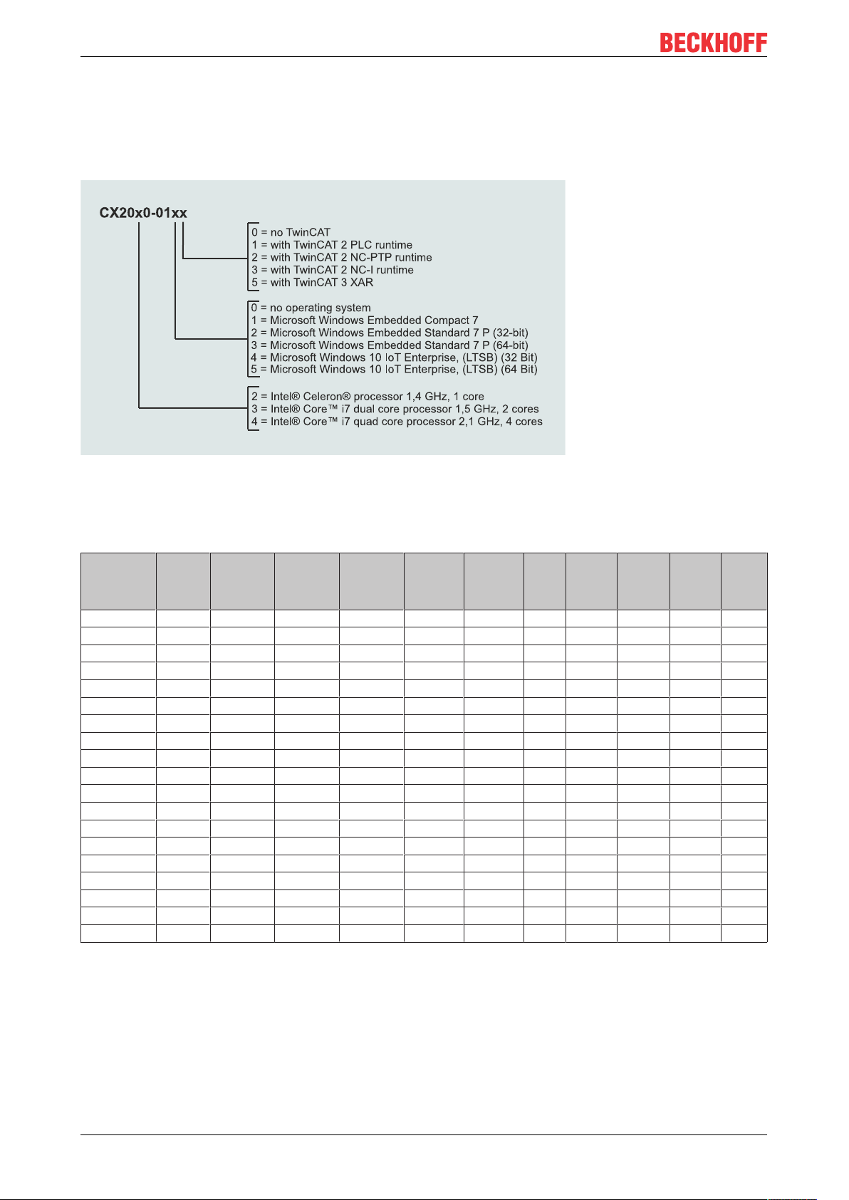
4.4 Types
The basic CPU module can be ordered with different hardware and software options. Use this overview in
conjunction with the information on the name plate to ascertain the hardware, operating system and
TwinCAT version of the basic CPU module.
Fig.4: Nomenclature for the basic CPU module.
The basic CPU module CX2020, CX2030 and CX2040 is available with the following software options:
Table5: CX20x0, ordering information for software.
Module no
operating system
CX20x0-0100 X - - - - - X - - - -
CX20x0-0110 - X - - - - X - - - -
CX20x0-0111 - X - - - - - X - - -
CX20x0-0112 - X - - - - - - X - -
CX20x0-0113 - X - - - - - - - X -
CX20x0-0115 - X - - - - - - - - X
CX20x0-0120 - - X - - - X - - - -
CX20x0-0121 - - X - - - - X - - -
CX20x0-0122 - - X - - - - - X - -
CX20x0-0123 - - X - - - - - - X -
CX20x0-0125 - - X - - - - - - - X
CX20x0-0130 - - - X - - X - - - -
CX20x0-0135 - - - X - - - - - - X
CX20x0-0140 - - - - X - X - - - -
CX20x0-0141 - - - - X - - X - - -
CX20x0-0142 - - - - X - - - X - -
CX20x0-0143 - - - - X - - - - X -
CX20x0-0150 - - - - - X X - - - -
CX20x0-0155 - - - - - X - - - - X
Windows
Embedded
Compact 7
Windows
Embedded
Standard 7
P (32-Bit)
Windows
Embedded
Standard 7
P (64-Bit)
Windows
10 IoT Enterprise,
32 Bit
Windows
10 IoT Enterprise,
64 Bit
no
TwinCAT
TwinCAT 2
PLCRuntime
TwinCAT 2
NC-PTPRuntime
TwinCAT 2
NC-IRuntime
TwinCAT 3
XAR
1)
1)
TwinCAT 3 supports only one CPU core. Applies to CX2030 and CX2040.
A CX20x0 Embedded PC with Microsoft Windows Embedded Compact 7 requires a CFast card with a
minimum capacity of 20 GB. For Microsoft Windows Embedded Standard 7 P and Microsoft Windows 10 IoT
Enterprise a CFast card with a minimum capacity of 40 GB is required.
CX20x018 Version: 2.5
Page 19
Product overview
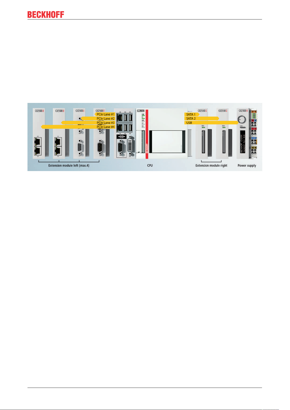
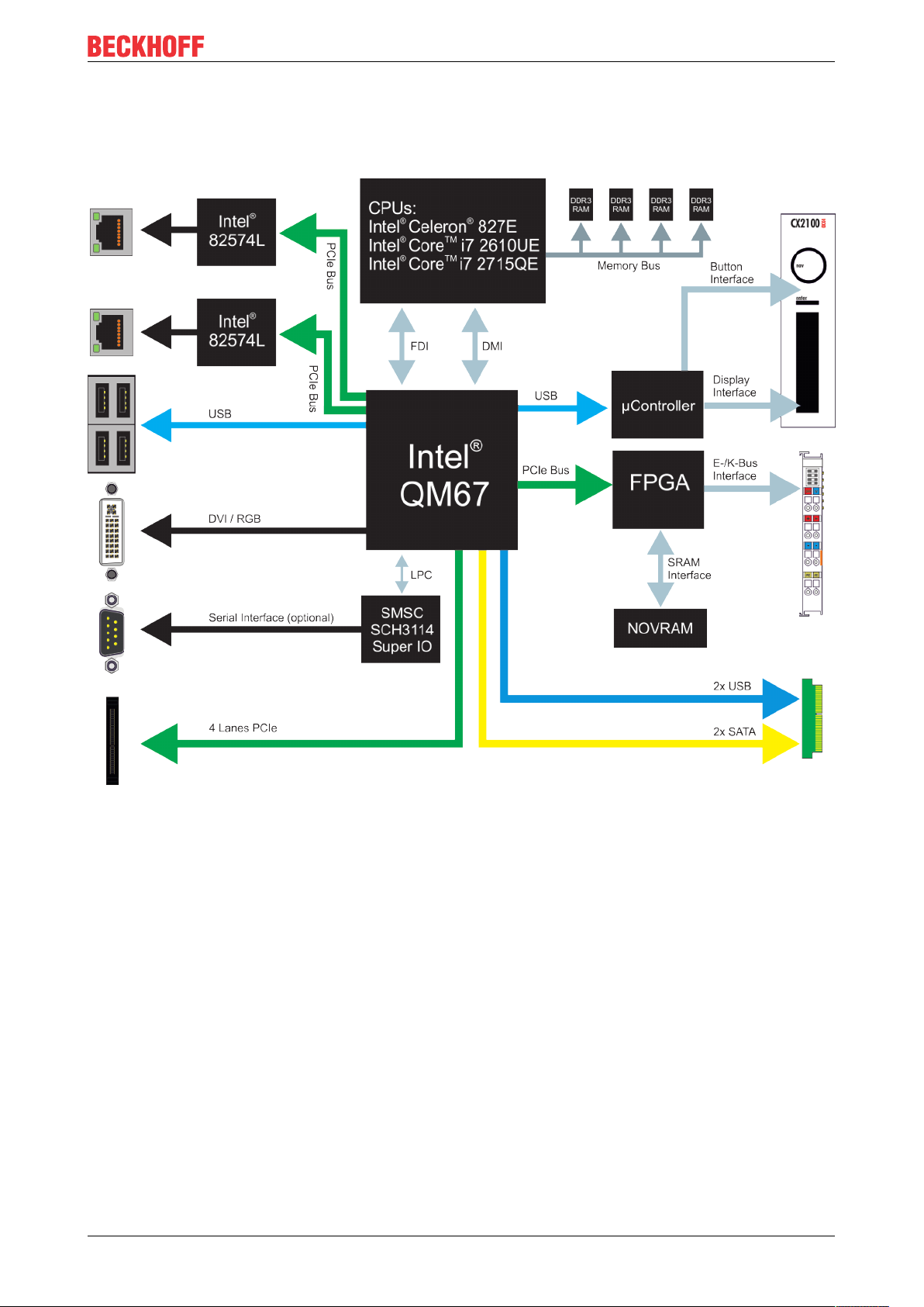
4.5 Architekture overview
The Embedded PCs of the CX20x0 family all have the same architecture. The architecture is described
below.
Fig.5: CX20x0 architecture overview.
The CX20x0 Embedded PCs are based on the Sandy Bridge microarchitecture developed by Intel. The
following CPUs are used:
• Intel®Celeron® 827E (Singlecore),
• Intel®CORETM i7 2610UE (Dualcore),
• and Intel®CoreTM i7 2715QE (Quadcore).
In addition to the arithmetic unit, the CPU also contains the memory controller and the graphics controller.
The single-core processor uses the Intel® HD has as graphics core. The two Core
TM
i7 CPUs (dual or quad
core) feature an Intel® HD graphics 3000 core. This offers a somewhat higher performance than the Intel
HD graphics core, and the quad core offers a higher clock speed. For details on the CPUs please refer to
Intel. The memory is connected directly to the memory controller. The Embedded PCs are available in two
memory configurations: 2GB or 4GB DDR3 RAM. The memory is not expandable and must be ordered ex
factory.
All CX20x0 Embedded PCs use the Mobile Intel® QM67 Express chipset (Intel® BD82QM67 PCH). This
chip provides all required interfaces:
• 4 x USB 2.0
• 1x USB 2.0 internal (power supply unit control button / display).
• DVI-I and DVI-D interface (second interface optional CX20x0-N010).
CX20x0 19Version: 2.5
®
Page 20

Product overview
• 1 PCIe lane for each of the two Intel® 82574L Gigabit Ethernet controllers
• LPC interface for super I/O controller for serial interface (CX20x0-N03x).
• 4 PCIe lanes via the multi-pin connection (left).
• 1 PCIe to FPGA for K-/E-bus and NOVRAM.
• 2x SATA internal via the multi-pole connection (right).
• 2x USB internal via the multi-pin connection (right).
The interfaces (USB, DVI, and LAN) are standard interfaces. Devices that meet the corresponding standard
can be connected to and operated at these interfaces. A VGA monitor can be connected to the DVI-I
interface with an adapter.
Intel® 82574L Gigabit Ethernet controllers are used as network controllers. There are two independent LAN
interfaces. Both LAN interfaces are gigabit-capable and support jumbo frames.
CX20x020 Version: 2.5
Page 21
Description of the interfaces
5 Description of the interfaces
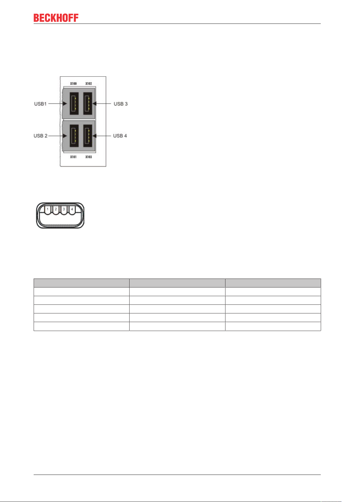
5.1 USB (X100, X101, X102, X103)
Fig.6: USB interfaces (X100, X101, X102, X103).
The Embedded PC has four independent USB interfaces for connecting keyboards, mice, touchscreens and
other input or data storage devices.
Fig.7: USB interface, pin numbering.
Note the power consumption of the individual devices. Each interface is limited to 500mA. The USB
interface is of type A and corresponds to the USB 2.0 specification.
Table6: USB interfaces (X100, X101, X102, X103), pin assignment.
Pin Assignment Typical assignment
1 VBUS Red
2 D- White
3 D+ Green
4 GND Black
Shell Shield Drain Wire
CX20x0 21Version: 2.5
Page 22
Description of the interfaces
X000
X001
LAN 1
LAN 2
LINK / ACT 2
SPEED 2
LINK / ACT 1
SPEED 1
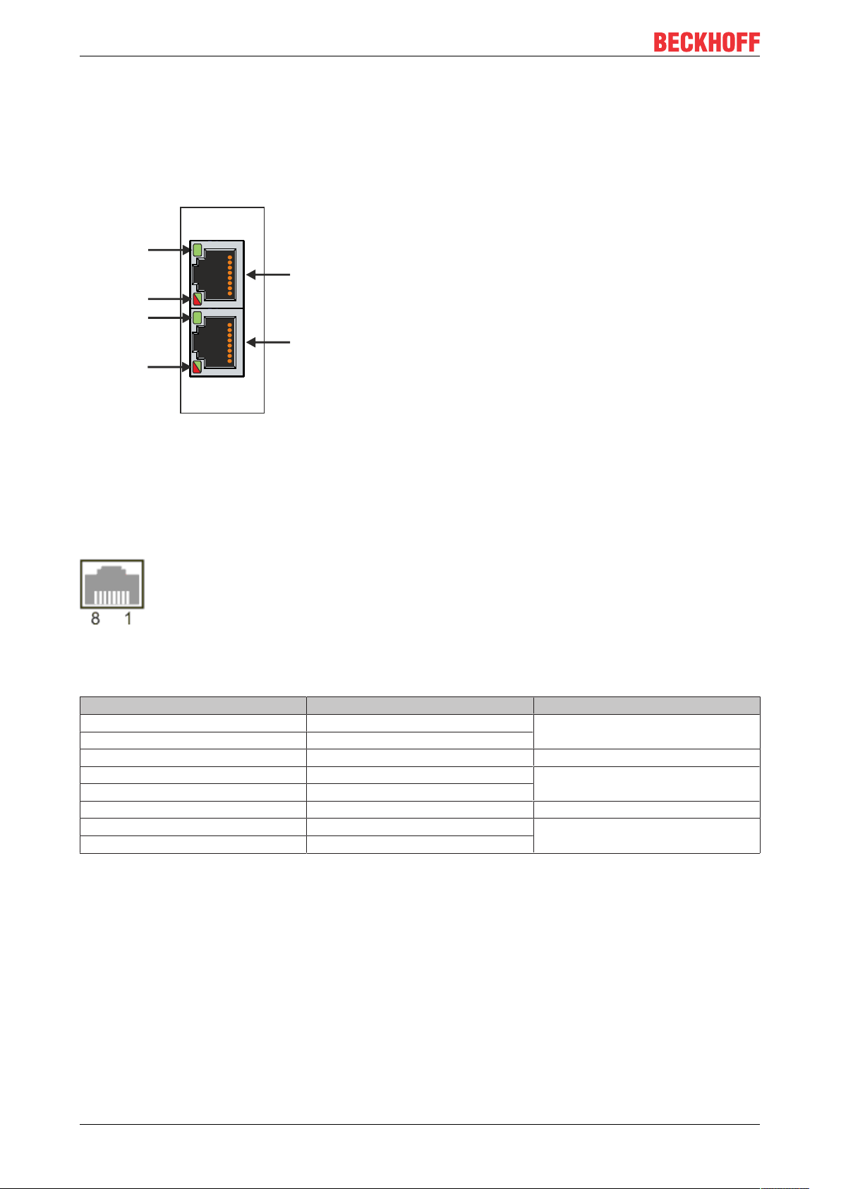
5.2 Ethernet RJ45 (X000, X001)
The two Ethernet interfaces are independent; no switch is integrated. The independent Ethernet interfaces
can be configured in different ways. In delivery state the Ethernet interfaces (X000, X001) are configured for
EtherCAT communication.
Note that an additional switch is required for a line topology.
Fig.8: Ethernet interface X000, X001.
Both Ethernet interfaces reach speeds of 10 / 100 / 1000 Mbit. The LEDs on the left of the interfaces indicate
the connection status. The upper LED (LINK/ACT) indicates whether the interface is connected to a network.
If this is the case the LED is green. The LED flashes when data transfer is in progress.
The lower LED (SPEED) indicates the connection speed. The LED does not light up if the speed is 10 Mbit.
The LED is green if the speed is 100 Mbit. The LED lights up red if the speed is 1000 Mbit (gigabit).
Fig.9: Ethernet interface, pin numbering.
Table7: Ethernet interface X000 and X001, pin assignment.
PIN Signal Description
1 T2 + Pair 2
2 T2 -
3 T3 + Pair 3
4 T1 + Pair 1
5 T1 -
6 T3 - Pair 3
7 T4 + Pair 4
8 T4 -
CX20x022 Version: 2.5
Page 23
Description of the interfaces
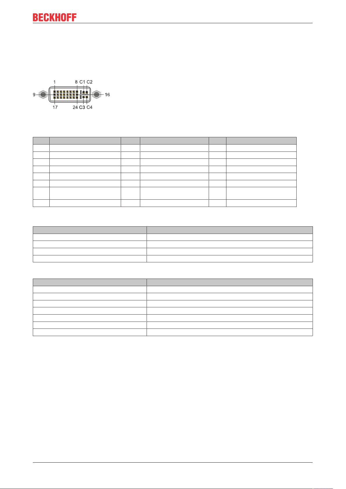
5.3 DVI-I (X200)
The DVI-I interface (X200) transfers digital data and is suitable for connection to digital or analog monitors.
The resolution at the display or the Beckhoff Control Panel depends on the distance from the display device.
The maximum distance is 5 m. Beckhoff offers various Panels with an integrated “DVI extension”. These
make a cable length of up to 50 meters possible.
Fig.10: DVI-I interface X200.
Table8: DVI-I interface X200, pin assignment.
Pin Assignment Pin Assignment Pin Assignment
1 TMDS Data 2- 9 TMDS Data 1- 17 TMDS Data 0-
2 TMDS Data 2+ 10 TMDS Data 1+ 18 TMDS Data 0+
3 TMDS Data 2/4 Shield 11 TMDS Data 1/3 Shield 19 TMDS Data 0/5 Shield
4 not connected 12 not connected 20 not connected
5 not connected 13 not connected 21 not connected
6 DDC Clock 14 + 5V Power 22 TMDS Clock Shield
7 DDC Data 15 Ground ( +5V, Analog H/V
Sync)
8 Analog Vertical Sync 16 Hot Plug Detect 24 TMDA Clock -
23 TMDS Clock +
Table9: DVI-I cross, pin assignment.
Pin Assignment
C1 Analog Red Video Out
C2 Analog Green Video Out
C3 Analog Blue Video Out
C4 Analog Horizontal Sync
Table10: DVI-I interface X200, resolution at the monitor.
Resolution in pixels Distance of the interface from the monitor
1920 x 1200 5 m
1920 x 1080 5 m
1600 x 1200 5 m
1280 x 1024 5 m
1024 x 768 5 m
800 x 600 5 m
640 x 480 5 m
The Embedded PC also supports higher resolutions, based on the DVI standard. A maximum resolution of
2560 x 1440 pixels can be set on the Embedded PC. Whether this resolution is achieved depends on the
monitor, the cable quality and the cable length.
CX20x0 23Version: 2.5
Page 24
Description of the interfaces
5.4 Optional interfaces
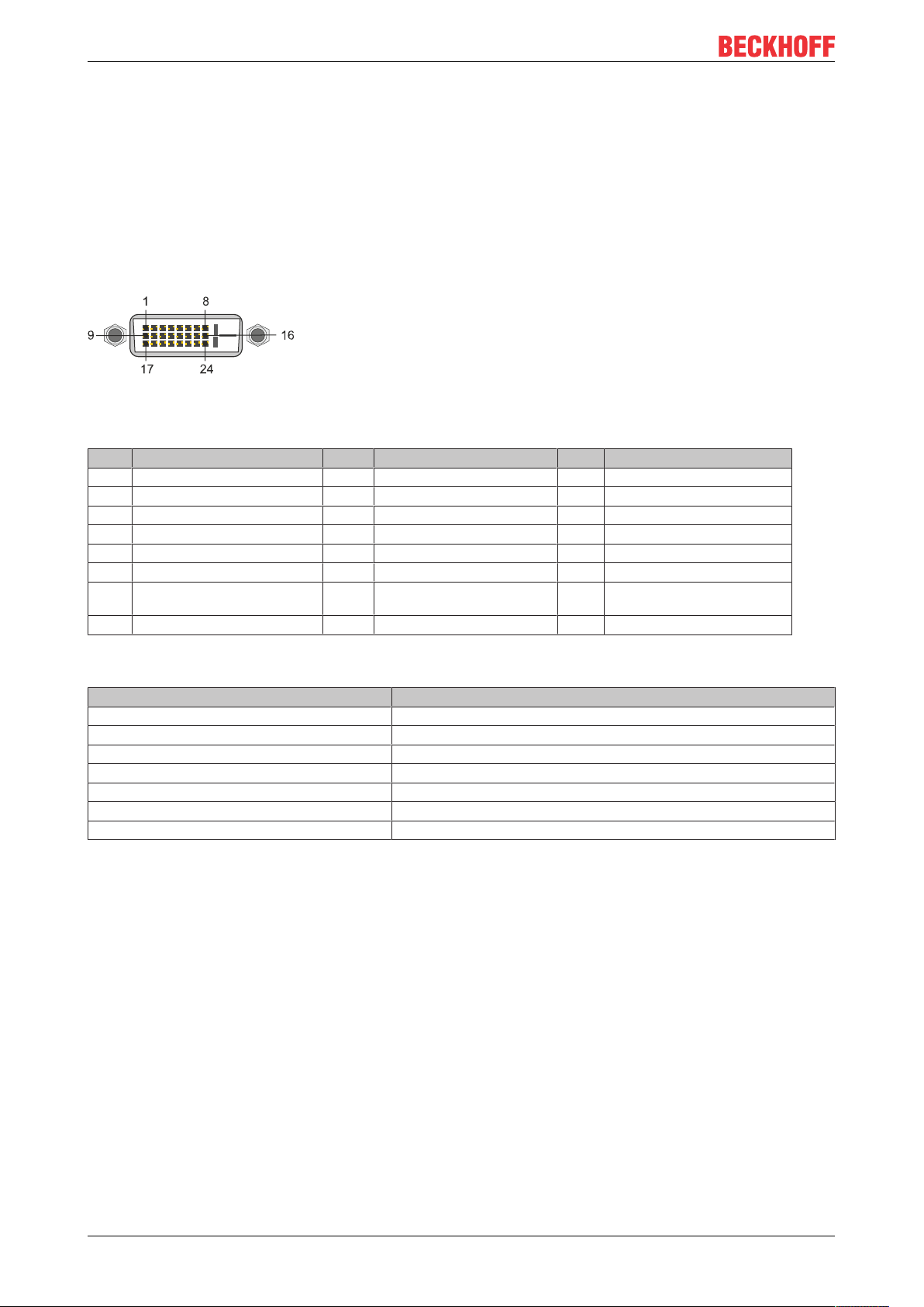
5.4.1 DVI-D (N010)
The DVI-D interface (X300) transfers digital data and is suitable for connection to digital displays. If the
optional N010 interface (DVI-D interface) is used, the first DVI-I interface can be operated either in VGA
mode or in DVI mode. The resolution at the display or the Beckhoff Control Panel depends on the distance
from the display device. The maximum distance is 5 m. Beckhoff offers various Panels with an integrated
“DVI extension”. These make a cable length of up to 50 meters possible.
Fig.11: DVI-D interface X300.
Table11: DVI-D interface X300, pin assignment.
Pin Assignment Pin Assignment Pin Assignment
1 TMDS Data 2- 9 TMDS Data 1- 17 TMDS Data 0-
2 TMDS Data 2+ 10 TMDS Data 1+ 18 TMDS Data 0+
3 TMDS Data 2/4 Shield 11 TMDS Data 1/3 Shield 19 TMDS Data 0/5 Shield
4 not connected 12 not connected 20 not connected
5 not connected 13 not connected 21 not connected
6 DDC Clock 14 + 5V Power 22 TMDS Clock Shield
7 DDC Data 15 Ground ( +5V, Analog H/V
Sync)
8 Analog Vertical Sync 16 Hot Plug Detect 24 TMDA Clock -
23 TMDS Clock +
Table12: DVI-D interface X300, resolution at the monitor.
Resolution in pixels Distance of the interface from the monitor
1920 x 1200 5 m
1920 x 1080 5 m
1600 x 1200 5 m
1280 x 1024 5 m
1024 x 768 5 m
800 x 600 5 m
640 x 480 5 m
The Embedded PC also supports higher resolutions, based on the DVI standard. A maximum resolution of
2560 x 1440 pixels can be set on the Embedded PC. Whether this resolution is achieved depends on the
monitor, the cable quality and the cable length.
CX20x024 Version: 2.5
Page 25
Description of the interfaces
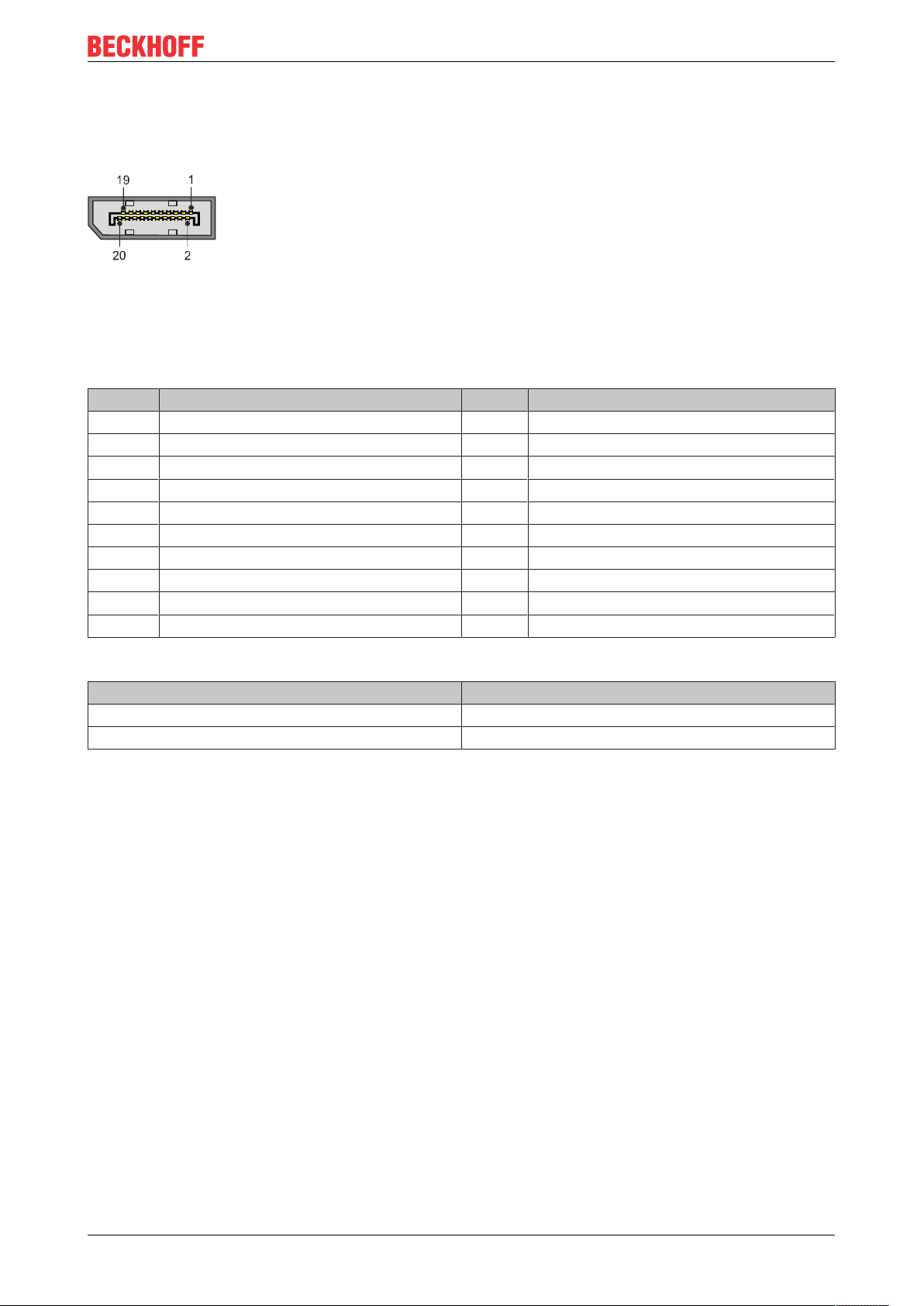
5.4.2 DisplayPort (N011)
The DisplayPort transfers image and audio signal at the same time and is therefore suitable for connecting
panels or monitors to the Embedded PC.
Fig.12: DisplayPort X300.
Version 1.1a of the DisplayPort (DisplayPort++) is installed on the Embedded PC. Adapters from DisplayPort
to DVI-D or DisplayPort to HDMI can be used to connect monitors without DisplayPort to the Embedded PC.
Table13: DisplayPort, pin assignment.
Pin Assignment Pin Assignment
1 LVDS lane 0+ 2 Ground
3 LVDS lane 0- 4 LVDS lane 1+
5 Ground 6 LVDS lane 1-
7 LVDS lane 2+ 8 Ground
9 LVDS lane 2- 10 LVDS lane 3+
11 Ground 12 LVDS lane 3-
13 Config 1 14 Config 2
15 AUX channel+ 16 Ground
17 AUX channel- 18 Hot-plug detection
19 Power supply: ground 20 Power supply: 3.3 V / 500 mA
Table14: DisplayPort X300, resolution at the monitor.
Interface Resolution in pixels
DisplayPort max. 2560 x 1600 @ 60 Hz
DisplayPort with adapter, DisplayPort to DVI-D max. 1600 x 1200 @ 60 Hz
CX20x0 25Version: 2.5
Page 26
Description of the interfaces
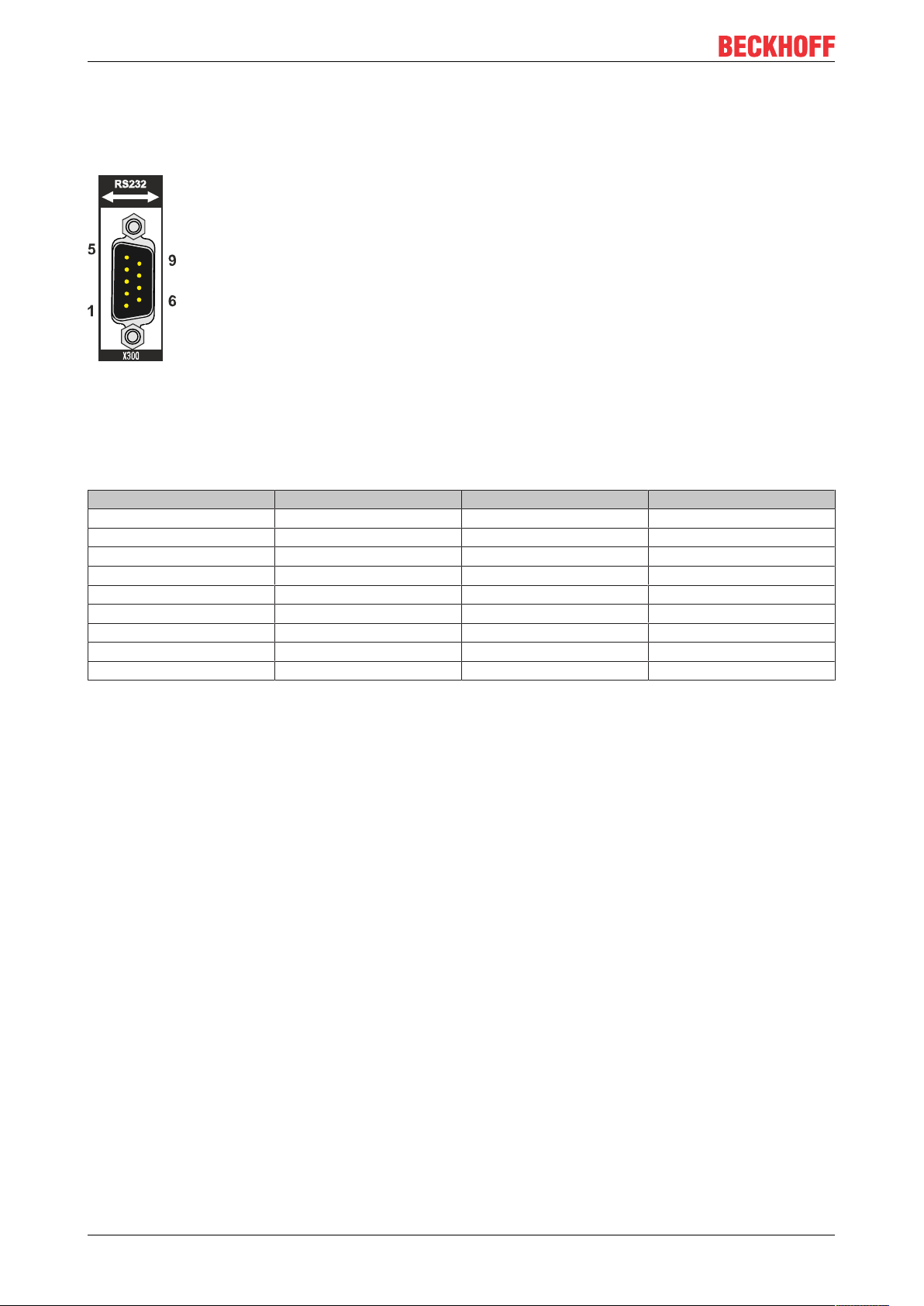
5.4.3 RS232 (N030)
The optional N030 interface provides an RS232 interface (X300). The RS232 interface is implemented on a
9-pin D-sub connector.
Fig.13: RS232 interface X300 with pin numbering.
The maximum baud rate on both channels is 115 kbit. The interface parameters are set via the operating
system or from the PLC program.
Table15: RS232 interface X300, pin assignment.
PIN Signal Type Description
1 DCD Signal in Data Carrier Detected
2 RxD Signal in Receive Data
3 TxD Signal out Transmit Data
4 DTR Signal out Data Terminal Ready
5 GND Ground Ground
6 DSR Signal in Dataset Ready
7 RTS Signal out Request to Send
8 CTS Signal in Clear to Send
9 RI Signal in Ring Indicator
CX20x026 Version: 2.5
Page 27
Description of the interfaces
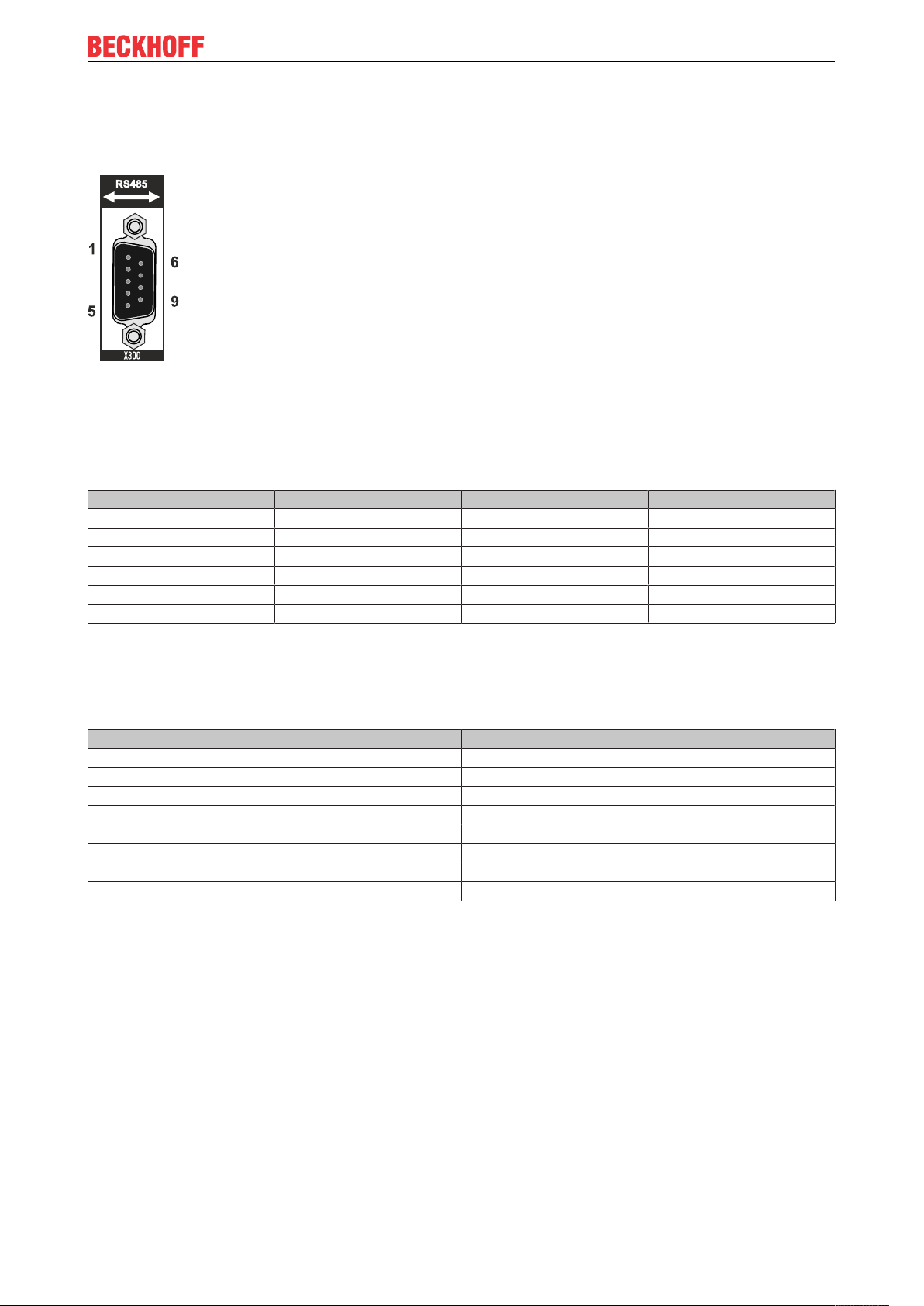
5.4.4 RS422/RS485 (N031)
The optional N031 interface provides an RS422 or RS485 interface (X300). The interface is implemented on
a 9-pin D-sub connector.
Fig.14: RS485 interface X300 with pin numbering.
The maximum baud rate on both channels is 115 kbit. The interface parameters are set via the operating
system or from the PLC program.
Table16: RS422/485 interface, pin assignment.
PIN Signal Type Description
2 TxD+ Data-Out + Transmit 422
3 RxD+ Data-In + Receive 422
5 GND Ground Ground
6 VCC VCC +5 V
7 TxD- Data-Out - Transmit 422
8 RxD- Data-In - Receive 422
For RS485 pins 2 and 3 (data +) must be connected, and pins 7 and 8 (data –).
By default the interface is parameterized as follows on delivery:
Table17: Default setting, RS485 without echo with end point (terminated).
Function Status
Echo on off
Echo off on
Auto send on on
Always send on off
Auto receive on on
Always receive on off
Term on on
Term on On
Other configurations for the RS485 interface
Other configurations for the RS485 interface can be ordered ex factory. The following options are available:
• N031-0001 RS485 with echo, end point (terminated).
• N031-0002 RS485 without echo, stub (without termination).
• N031-0003 RS485 with echo, stub (without termination).
• N031-0004 RS422 full duplex end point (terminated).
An RS485 interface cannot be configured retrospectively and must always be ordered ex factory as required.
CX20x0 27Version: 2.5
Page 28
Description of the interfaces
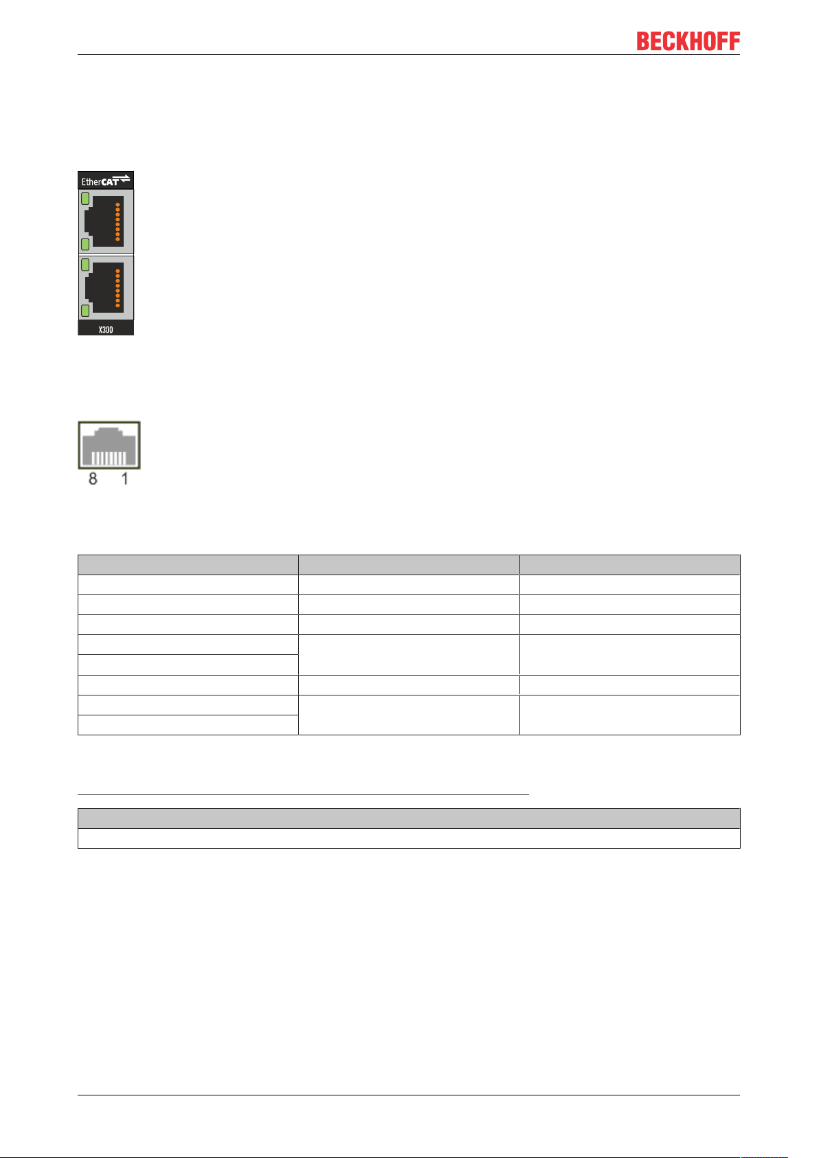
5.4.5 EtherCAT slave (B110)
The latest generation of Embedded PCs can be ordered ex factory with an EtherCAT slave interface (B110).
On the devices the optional B110 interface is referred to as X300.
Fig.15: EtherCAT slave interface X300.
The incoming EtherCAT signal is connected to the upper LAN interface. The lower LAN interface relays the
signal to other EtherCAT slave devices.
Fig.16: EtherCAT slave LAN interface, pin numbering.
Table18: EtherCAT slave interface X300, pin assignment.
PIN Signal Description
1 TD + Transmit +
2 TD - Transmit -
3 RD + Receive +
4 connected reserved
5
6 RD - Receive -
7 connected reserved
8
For the optional EtherCAT slave interface (B110), documentation with further information is available for
download from the Beckhoff website:
https://www.beckhoff.de/german/download/epc.htm?id=71003127100362
Document name
CXxxx0-B110 optional interface EtherCAT slave.
CX20x028 Version: 2.5
Page 29

5.4.6 PROFIBUS (x310)
Description of the interfaces
Pin 6 transfers 5V
pin 5 transfers GND for the active termination resistor. These must never be used for
DC,
other functions, as this can lead to destruction of the device.
Pins 3 and 8 transfer the PROFIBUS signals. These must never be swapped over, as this will prevent
communication.
Fig.17: PROFIBUS interface X310 with pin numbering.
The Profibus bus line is connected via a 9-pin D sub with the following pin assignment:
Table19: PROFIBUS interface X310, pin assignment.
Pin Assignment
1 Shielding
2 not used
3 RxD/TxD-P
4 not used
5 GND
6 +5 V
DC
7 not used
8 RxD/TxD-N
9 not used
Table20: Wire colors of the PROFIBUS line.
PROFIBUS line D sub
B red Pin 3
A green Pin 8
For the optional PROFIBUS interface (x310), documentation with further information is available for
download from the Beckhoff website:
https://www.beckhoff.de/german/download/epc.htm?id=71003127100362
Document name
CXxxx0-x310 optional Profibus interface.
CX20x0 29Version: 2.5
Page 30

Description of the interfaces
5.4.7 CANopen (x510)
Fig.18: CANopen interface X510 with pin numbering.
The CAN bus line is connected via a 9-pin D-sub socket with the following configuration:
Table21: CANopen interface X510, pin assignment.
Pin Assignment
1 not used
2 CAN low (CAN-)
3 CAN ground (internally connected to pin 6)
4 not used
5 Shield
6 CAN ground (internally connected to pin 3)
7 CAN high (CAN+)
8 not used
9 not used
For the optional CANopen interface (x510), documentation with further information is available for download
from the Beckhoff website:
https://www.beckhoff.de/german/download/epc.htm?id=71003127100362
Document name
CXxxx0-x510 optional CANopen interface.
CX20x030 Version: 2.5
Page 31

5.4.8 PROFINET RT (x930)
Fig.19: PROFINET RT interface X300.
Fig.20: PROFINET RT LAN interface, pin numbering.
Table22: PROFINET RT interface, pin assignment.
Description of the interfaces
PIN Signal Description
1 TD + Transmit +
2 TD - Transmit -
3 RD + Receive +
4 connected reserved
5
6 RD - Receive -
7 connected reserved
8
CX20x0 31Version: 2.5
Page 32

Commissioning
1
2
3
7
4
5
8
6
2
6 Commissioning
6.1 Selecting the appropriate CX2100 power supply unit
The basic CPU module requires a power supply unit of type CX2100-0xxx. Connect the power supply unit to
the multi-pin port on the right of the basic CPU module.
When installed horizontally, any type CX2100-0xxx power supply unit can be used.
Table23: Power supply units for horizontal installation.
Basic CPU module Power supply units
CX2020
CX2030
CX2040 CX2100-0014 (130 W, from HW version: 2.4)
The Embedded PCs CX2020 and CX2030 can be ordered with active cooling ex factory, for operation in
vertical or horizontal installation position. In this case only CX2100-0014 or CX2100-0914 power supply units
should be used, which feature additional ventilation openings and larger heat sinks.
CX2100-0004 (45 W)
CX2100-0014 (130 W, from HW version: 2.4)
CX2100-0904 (45 W, capacitive UPS)
CX2100-0914 (100 W, external battery pack can be used)
CX2100-0914 (100 W, external battery pack can be used)
The Embedded PC CX2040 is equipped with a fan cartridge as standard. It can be operated in vertical or
horizontal installation position and requires power supply units of type CX2100-0014 or CX2100-0914.
Table24: Power supply units for vertical installation.
Basic CPU module Accessories Power supply units
CX2020 Fan option CX2900-0200 CX2100-0014 (130 W, from HW version: 2.4)
CX2030 Fan option CX2900-0300
CX2040 -
-or-
CX2100-0914
(100 W, external battery pack can be used)
Configuration of the power supply terminal
Fig.21: Embedded PC CX2020 with power supply unit CX2100-0004, configuration of the power supply
terminal.
Table25: Legend for configuration of the power supply terminal.
No. Description No. Description
1 Diagnostic LEDs 5 0 V, Bus Terminal supply
2 Terminal bus (K- or E-bus) 6 Terminal release
3 +24 V and 0 V, for basic CPU module 7 PE, spring-loaded terminal
4 +24 V, Bus Terminal supply 8 +24 V, 0 V, PE, for power contacts
CX20x032 Version: 2.5
Page 33

Commissioning
24V 0V
++
- -
PE PE
0004
FB1
PWR
TC
FB2
HDD
BECKHOFF
CX2020
24V 0V
++
- -
PE PE
6.2 Mounting
6.2.1 Attaching the power supply unit
The basic CPU module requires a power supply unit of type CX2100-0xxx. Connect the power supply unit to
the multi-pin port on the right of the basic CPU module.
Proceed as follows:
1. Select the appropriate power supply unit, as described in chapter Selecting the appropriate CX2100
power supply unit [}32].
2. Attach the power supply unit on the right of the basic CPU module.
ð Next you can install the bar clips.
6.2.2 Installing the bar clips
Usually, the connection between the modules is strong enough. However, the basic CPU module and the
attached modules may be subjected to shocks, vibrations or other impacts. The modules can be securely
connected to one another with the aid of bar clips.
Install the bar clips as follows:
1. Attach the bar clips at the top and bottom between the cooling fins.
2. Push the bar clips between the cooling fins of your devices, as shown in the image below.
ð The bar clips have been installed successfully, if they don't protrude and are level with the cooling fins of
your modules.
Once all modules are latched, the devices can be installed on the mounting rail.
CX20x0 33Version: 2.5
Page 34

Commissioning
min. 30 mm
24V 0V
PE
+
-PE-
+
BECKHOFF
KL 9010
24V 0V
PE-PE
-
BECKHOFF
KL 2134
+ +
24V 0V
PE
- -
+
BECKHOFF
KL 1002
+
PEPE
FB1
PWR
TC
FB2
HDD
24V 0V
++
- -
PE PE
BECKHOFF
CX2020
CX2100
enter
nav
0004
CX2100
enter
nav
0004
min. 30 mm
24V 0V
PE
+
-PE-
+
BECKHOFF
KL 9010
24V 0V
PE-PE
-
BECKHOFF
KL 2134
+ +
24V 0V
PE
- -
+
BECKHOFF
KL 1002
+
PEPE
FB1
PWR
TC
FB2
HDD
24V 0V
++
- -
PE PE
BECKHOFF
CX2020
CX2100
enter
nav
0004
CX2100
enter
nav
0004
6.2.3 Note the permissible installation positions
Increased heat generation
The Embedded PC may overheat if the installation position is incorrect or the minimum distances
are not adhered to.
The Embedded PC may only be operated at ambient temperatures of up to 60 °C. Ensure adequate
ventilation. Select a horizontal installation position. Leave at least 30 mm clearance above and below the Embedded PC.
Install the Embedded PC horizontally in the control cabinet on a mounting rail, in order to ensure optimum
heat dissipation. Only Embedded PCs with active cooling can be operated vertically or horizontally.
Table26: Embedded PC CX20x0, installation position depending on the cooling option.
Embedded PCs Horizontal installation position Vertical and horizontal installation
position
CX2020 X -
CX2030 X -
CX2040 with active cooling X X
CX2020 with CX2900-0200 fan option X X
CX2030 with CX2900-0200 fan option X X
Note the following specifications for the control cabinet:
• The Embedded PC should only be operated at ambient temperatures between -25 °C and 60 °C.
Measure the temperature below the Embedded PC at a distance of 30 mm to the cooling fins, in order
to determine the ambient temperature correctly.
• Adhere to the minimum distances of 30 mm above and below the Embedded PCs.
• Additional electrical equipment affects the heat generation in the control cabinet. Select a suitable
control cabinet enclosure depending on the application, or ensure that excess heat is dissipated from
the control cabinet.
Permitted installation position without fan
The Embedded PC must be installed horizontally on the mounting rail. Ventilation openings are located at
the top and bottom of the housing. This ensures an optimum airflow through the Embedded PC in vertical
direction. In addition, a minimum clearance of 30 mm above and below the Embedded PCs required, in order
to ensure adequate ventilation.
Fig.22: Embedded PC CX20x0, horizontal installation position.
If vibrations and impact occurs in the same direction as the mounting rail, the Embedded PC must be
secured with an additional bracket, in order to prevent it slipping.
CX20x034 Version: 2.5
Page 35

24V 0V
PE
+
-
PE
-
+
BECKHOFF
KL 9010
24V 0V
PE
-
PE
-
BECKHOFF
KL 2134
+ +
24V 0V
PE
- -
+
BECKHOFF
KL 1002
+
PEPE
FB1
PWRTCFB2
HDD
24V 0V
++
- -
PE PE
BECKHOFF
CX2020
CX2100
enter
nav
0004
24V 0V
PE
+
-
PE
-
+
BECKHOFF
KL 9010
24V 0V
PE
-
PE
-
BECKHOFF
KL 2134
+ +
24V 0V
PE
- -
+
BECKHOFF
KL 1002
+
PEPE
FB1
PWR
TC
FB2
HDD
24V 0V
++
- -
PE PE
BECKHOFF
CX2020
CX2100
enter
nav
0004
Fig.23: Embedded PC CX20x0, unacceptable installation positions without fan.
Permitted installation positions with fan
Commissioning
Only Embedded PCs with an active cooling can be installed vertically or horizontally on the mounting rail.
Without active cooling the Embedded PC is not ventilated adequately in vertical or horizontal position. In this
case only the power supply units CX2100-0014 or CX2100-0914 should be used.
Fig.24: Embedded PC CX20x0, permitted installation positions with fan.
Even with active cooling, the ambient temperature range between -25 and 60 °C and the minimum distances
of 30 mm above and below the Embedded PC should be adhered to. Secure the Embedded PC with an
additional bracket, in order to prevent it slipping from the DIN rail.
Ensure that Bus Terminals that are connected to the Embedded PC are designed for operation in vertical or
horizontal position.
CX20x0 35Version: 2.5
Page 36

Commissioning
6.2.4 Attaching on mounting rail
The housing is designed such that the Embedded PC can be pushed against the mounting rail and latched
onto it.
Requirements:
• Mounting rail of type TS35/7.5 or TS35/15 according to DIN EN 60715.
Secure the Embedded PC on the mounting rail as follows:
1. Unlock the latches at the top and bottom.
2. Place the Embedded PC at the front of the mounting rail. Slightly press the Embedded PC onto the
mounting rail until a soft click can be heard and the Embedded PC has latched.
3. Then lock the latches again.
ð You have installed the Embedded PC successfully. Double-check the correct installation and latching of
the Embedded PC on the mounting rail.
CX20x036 Version: 2.5
Page 37

Commissioning
6.2.5 CFast card installation and removal
Loss of data
CFast cards are subjected to heavy load during operation and have to withstand many write cycles
and extreme ambient conditions. CFast cards from other manufacturer may fail, resulting in data
loss.
Only use industrial CFast cards provided by Beckhoff.
A CFast card is a non-volatile memory. Data to be retained in the event of a power failure should be saved
on the CFast card. The CFast cards supplied by Beckhoff are industrial cards with an increased number of
write cycles and an extended temperature range (+85 °C).
The eject mechanism is based on the push/push principle. The installation and removal of CFast cards is
described below.
Requirements:
• The basic CPU module must be switched off. The CFast cards may only be installed or removed in
switched off state.
Removing a CFast card
1. Gently push the CFast card.
A soft click can be heard when the card is released.
2. The card is lifted by approx. 4 mm from the housing. Pull out the card.
Installing a CFast card
1. Push the CFast card into the CFast card slot.
2. A soft click can be heard when the card engages.
ð The card is seated correctly if it is flush with the front side of the device housing.
CX20x0 37Version: 2.5
Page 38

Commissioning
5 VB
EL 2032
BECKHOFF
EL 2032
BECKHOFF
EL 9070
BECKHOFF
FB1
PWR
TC
FB2
HDD
24V 0V
++
- -
PE PE
BECKHOFF
CX2020
CX2100
enter
nav
0004
EL 2032
BECKHOFF
EL 2032
BECKHOFF
EL 2032
BECKHOFF
EL 2032
BECKHOFF
5 VB
EL 2032
BECKHOFF
EL 9070
BECKHOFF
EL 2032
BECKHOFF
FB1
PWR
TC
FB2
HDD
24V 0V
++
- -
PE PE
BECKHOFF
CX2020
CX2100
enter
nav
0004
EL 2032
BECKHOFF
EL 2032
BECKHOFF
EL 2032
BECKHOFF
EL 2032
BECKHOFF
6.2.6 Installing passive EtherCAT Terminals
Incorrectly installed passive EtherCAT Terminals
The E-bus signal between an Embedded PC and the EtherCAT Terminals can be impaired due to
incorrectly installed passive EtherCAT Terminals.
Passive EtherCAT Terminals should not be installed directly on the power supply unit.
EtherCAT Terminals that do not take part in active data exchange are referred to as passive terminals.
Passive EtherCAT Terminals have no process image and do not require current from the terminal bus (Ebus).
Passive EtherCAT Terminals (e.g. EL9195) can be detected in TwinCAT. In the tree structure the EtherCAT
Terminal is displayed without process image, and the value in column “E-bus (mA)” does not change,
compared to the preceding EtherCAT Terminal.
Fig.25: Identifying a passive EtherCAT Terminal in TwinCAT.
The entry "Current consumption via E-Bus" in the technical data of an EtherCAT Terminal indicates whether
a particular EtherCAT Terminal requires power from the terminal bus (E-bus).
The following diagram shows the permissible installation of a passive EtherCAT Terminal. The passive
EtherCAT Terminal was not directly attached to the power supply unit.
Fig.26: Passive EtherCAT Terminals, permissible installation.
The following diagram shows the invalid installation of a passive EtherCAT Terminal.
Fig.27: Passive EtherCAT Terminals, invalid installation.
CX20x038 Version: 2.5
Page 39

Commissioning
1
2
3
4
8
6.3 Connecting the power supply
NOTE
Damage to the Embedded PCs
The Embedded PCs may be damaged during wiring.
• The cables for the power supply should only be connected in de-energized state.
The power supply units require an external voltage source, which provides 24 V DC (-15% /+20%).
The cabling of the Embedded PC in the control cabinet must be done in accordance with the standard EN
60204-1:2006 PELV = Protective Extra Low Voltage:
• The "PE" and "0V" conductors of the voltage source for a basic CPU module must be on the same
potential (connected in the control cabinet).
• Standard EN 60204-1:2006, section 6.4.1:b stipulates that one side of the circuit, or a point of the
energy source for this circuit must be connected to the protective earth conductor system.
Connection example with CX2020 basic CPU module and CX2100-0004 power supply unit:
Table27: Legend for the connection example.
No. Description
1 The upper spring-loaded terminals identified with "24V" and "0V" supply the basic CPU
module and the terminal bus (data transfer via K- or E-bus).
2 The spring-loaded terminals identified as "+", "-" and "PE" supply the Bus Terminals via
the power contacts and the sensors or actuators connected to the Bus Terminals.
CX20x0 39Version: 2.5
Page 40

Commissioning
FB1
PWR
TC
FB2
HDD
24V 0V
++
- -
PE PE
BECKHOFF
CX2020
CX2100
enter
nav
0004
24V
0V
+
+
3
1
2
The cables of an external voltage source are connected to the power supply unit with spring-loaded
terminals.
Table28: Required wire cross-sections and strip lengths.
Conductor cross-section 0,5 ... 2,5 mm
2
AWG 20 ... AWG 14
Strip length 8 ... 9 mm 0.33 inch
Connect the Embedded PC as follows:
1. Open a spring-loaded terminal by slightly pushing with a screwdriver or a rod into the square opening
above the terminal.
2. The wire can now be inserted into the round terminal opening without any force.
3. The terminal closes automatically when the pressure is released, holding the wire safely and
permanently.
The voltage source has been connected to the power supply unit
successfully when the two upper power supply terminal LEDs light up in
green.
• The left LED (Us) indicates the supply of the basic CPU module and
terminal bus.
• The red LED (Up) indicates the Bus Terminal supply via the power
contacts.
NOTE
Interrupting / switching off the power supply
To switch off the Embedded PC, do not disconnect the ground (0 V), because otherwise current may continue to flow via the shielding, depending on the device, and damage the Embedded PC or peripheral devices.
• Always disconnect the 24 V line. Devices connected to the Embedded PC, which have their own power
supply (e.g. a Panel) must have the same potential for "PE" and "0 V" as the Embedded PC have (no
potential difference).
CX20x040 Version: 2.5
Page 41

Commissioning
6.4 Observe the UL requirements
The Embedded PCs CX20x0 and the power supply unit CX2100-0004 are UL508 certified. The
corresponding UL label can be found on the type plate.
Fig.28: UL label on the CX20x0.
The CX20x0 Embedded PCs can thus be used in areas in which special UL requirements have to be met.
UL requirements:
• The Embedded PCs must not be connected to unlimited voltage sources.
• Embedded PCs may only be supplied from a 24V DC voltage source. The voltage source must be
insulated and protected with a fuse of maximum 4 A (corresponding to UL248).
• Or the power supply must originate from a voltage source that corresponds to NEC class 2. An NEC
class 2 voltage source must not be connected in series or parallel with another NEC class 2 voltage
source.
CX20x0 41Version: 2.5
Page 42

Commissioning
6.5 Switching on
Please ensure that the Embedded PC is fully configured before switching on the Embedded PC.
Switch on the Embedded PC as follows:
1. Ensure that all extension, system and fieldbus modules are connected correctly.
2. Check whether the right CX2100 power supply unit and the right installation position were selected.
3. Check whether the Embedded PC is mounted securely on the DIN rail and all required Bus Terminals
are connected.
4. Only then switch on the power supply for the power supply unit.
ð The Embedded PC starts automatically when the external power supply is switched on. The pre-installed
operating system is started and all connected extension, system and fieldbus modules are configured.
6.6 Switching off
Loss of data
If the Embedded PC is switched off during operation, data on the CFast card or other hard disks
may be lost.
Do not disconnect the Embedded PC during operation.
Switch off the Embedded PC as follows:
1. Stop all running programs properly, e.g. the control software on the Embedded PC.
2. Shut down the operating system.
3. Do not switch off the external power supply until all other tasks have been completed, in order to switch
off the Embedded PC.
CX20x042 Version: 2.5
Page 43

Configuration
7 Configuration
7.1 Windows Embedded Compact 7
7.1.1 Scan for new hardware
Under Windows Embedded Compact 7 the Embedded PC scans for new hardware on the PCI bus the first
time it is started. After that the hardware is permanently registered and the saved configuration is used.
If other extension modules are plugged in after the first start, the Embedded PC no longer scans for new
hardware and the new extension modules will not be found.
Follow these steps to ensure that an Embedded PC running Windows Embedded Compact 7 scans for new
hardware again.
Requirements:
• Windows Embedded Compact 7
Proceed as follows:
1. Switch the Embedded PC off and remove the CFast card from the Embedded PC.
2. Insert the CFast card into an external card reader and open the CFast card's folder structure.
3. Delete the Documents and Settings folder on the CFast card.
4. Install the CFast card in the Embedded PC again.
5. Start the Embedded PC.
ð After starting, the Embedded PC scans for new hardware once again and saves the current hardware
configuration.
As soon as you change the hardware and plug in other extension modules, you must repeat these steps
and delete the Documents and Settings folder again.
CX20x0 43Version: 2.5
Page 44

Configuration
7.2 Windows Embedded Standard 7 P
7.2.1 Identification of the Ethernet interfaces (X000, X001)
Network and Sharing Center
In the Network and Sharing Center the Ethernet interfaces (X000, X001) of the CX20x0 Embedded PC are
identified as follows as standard:
• Local Area Connection 2 corresponds to Ethernet interface X000.
• Local Area Connection corresponds to Ethernet interface X001.
Fig.29: Windows 7, Identification of the Ethernet interfaces (X000, X001) in the Network and Sharing
Center.
Device Manager
In the Device Manager the Ethernet interfaces (X000, X001) of the CX20x0 Embedded PC are identified as
follows as standard:
• TwinCAT Intel PCI Ethernet adapter (gigabit) #2 corresponds to the Ethernet interface X000.
• TwinCAT Intel PCI Ethernet adapter (gigabit) corresponds to the Ethernet interface X001.
Fig.30: Windows 7, identification of the Ethernet interfaces (X000, X001) in the device manager.
CX20x044 Version: 2.5
Page 45

Configuration
7.2.2 Enabling jumbo frames
Standardized Ethernet frames have a size of 1518 bytes. Ethernet frames that are larger than 1518 bytes
are referred to as jumbo frames. Jumbo frames are used for transferring large data quantities. Jumbo frames
are useful for certain applications, e.g. video cameras.
The Ethernet interfaces (X000, X001) support jumbo frames only if the original Intel® driver is installed.
Requirements:
• The original Intel® driver can be downloaded from https://downloadcenter.intel.com.
• Install the original Intel® driver. Note that this will delete the real-time capable driver from Beckhoff.
• Check whether the peripheral devices support jumbo frames.
Jumbo frames are activated as follows:
1. Under Start > Control Panel > Hardware and Sound click on Device Manager.
2. Double-click on the interface and then on the Advanced tab.
3. Under Settings click on Jumbo Packet, under Value select the option 4088 bytes or 9014 bytes.
ð You have successfully activated jumbo frames, and you can now transfer larger data quantities.
CX20x0 45Version: 2.5
Page 46

Configuration
7.2.3 Set NIC Teaming
NIC Teaming consolidates several physical network cards to group, thereby creating redundancy.
Redundancy can help intercept interference in network cards or in the cabling by assigning the data transfer
to other devices in the group.
Requirements:
• The original Intel® driver can be downloaded from https://downloadcenter.intel.com.
• Install the original Intel® driver for the Network Interface Card. Note that this will delete the real-time
capable driver from Beckhoff.
NIC Teaming is set as follows:
1. Under Start > Control Panel > Hardware and Sound click on Device Manager.
2. Double-click on the interface.
3. Click on the Teaming tab.
4. Click on New Team and follow the installation instructions.
CX20x046 Version: 2.5
Page 47

5. Under Select a team type select the option Adapter Fault Tolerance
Configuration
6. Click on Next to complete the installation.
ð You have successful set NIC Teaming for your Ethernet interfaces. Further settings can be specified or
changed under the Settings tab.
CX20x0 47Version: 2.5
Page 48

Configuration
7.2.4 Restoring the Beckhoff real-time driver.
The Beckhoff real-time driver can be restored if the real-time driver was uninstalled or the original Intel®
driver for jumbo frames or NIC Teaming was installed, for example. This chapter shows you how to use
TcRteInstall.exe to restore the Beckhoff real-time driver. The file is in the TwinCAT directory by default.
Requirements:
• You can find the TcRteInstall.exe in a TwinCAT 2 standard installation under: C:\TwinCAT\Io
\TcRteInstall.exe
• And in a TwinCAT 3 standard installation under: C:\TwinCAT\3.1\System\TcRteInstall.exe
Proceed as follows:
1. Double-click the TcRteInstall.exe file.
The installation dialog appears and shows the compatible Ethernet interfaces under Compatible
devices.
2. Select the Ethernet interfaces for which you wish to restore the Beckhoff real-time driver and click on
Install.
ð The Beckhoff real-time driver is installed. The Ethernet interfaces with installed Beckhoff real-time driver
are shown under Installed and ready to use devices (real-time capable).
CX20x048 Version: 2.5
Page 49

Configuration
7.3 Windows 10 IoT Enterprise LTSB
7.3.1 Identification of the Ethernet interfaces (X000, X001)
Network and Sharing Center
In the Network and Sharing Center the Ethernet interfaces (X000, X001) of the CX20x0 Embedded PC are
identified as follows as standard:
• Ethernet 2 corresponds to the Ethernet interface X000.
• Ethernet corresponds to the Ethernet interface X001.
Fig.31: Windows 10, Identification of the Ethernet interfaces (X000, X001) in the Network and Sharing
Center.
Device Manager
In the Device Manager the Ethernet interfaces (X000, X001) of the CX20x0 Embedded PC are identified as
follows as standard:
• Intel(R) 82574L Gigabit Network Connection #2 corresponds to the Ethernet interface X000.
• Intel(R) 82574L Gigabit Network Connection corresponds to the Ethernet interface X001.
Fig.32: Windows 10, identification of the Ethernet interfaces (X000, X001) in the device manager.
CX20x0 49Version: 2.5
Page 50

Configuration
7.4 Beckhoff Device Manager
7.4.1 Starting the Beckhoff Device Manager
Using the Beckhoff Device Manager, an Industrial PC can be configured by remote access with the aid of a
web browser. Depending on the image version, access takes place via different protocols and requires
different open ports. For older image versions access takes place via the HTTP protocol and Port 80 (TCP).
More up-to-date image versions use HTTPS and Port 443 (TCP).
Requirements:
• Host PC and Embedded PC must be located in the same network. Depending on the operating system
version, the network firewall must allow access via port 80 (HTTP) or port 443 (HTTPS).
• IP address or host name of the Embedded PC.
Table29: Access data for the Beckhoff Device Manager on delivery.
Operating system Access data
Windows Embedded Standard 7,
Windows 10 IoT Enterprise LTSB
Windows Embedded Compact 7
User name: Administrator
Password: 1
Start the Beckhoff Device Manager as follows:
1. Open a web browser on the host PC.
2. Enter the IP address or the host name of the Industrial PC in the web browser to start the Beckhoff
Device Manager.
• Example with IP address: https://169.254.136.237/config
• Example with host name: https://CX-16C2B8/config
3. Enter the user name and password. The start page appears:
ð Navigate forward in the menu and configure the Industrial PC. Note that modifications only become
active once they have been confirmed. It may be necessary to restart the Industrial PC.
CX20x050 Version: 2.5
Page 51

Configuration
7.4.2 Enabling a remote display
So that you can remotely access an Industrial PC with CE operating system, you must first activate Remote
Display in the Beckhoff Device Manager. The remote display is disabled by default.
Requirements:
• Host PC and Embedded PC must be located in the same network. Depending on the operating system
version, the network firewall must allow access via port 80 (HTTP) or port 443 (HTTPS).
• The IP address or the host name of the Embedded PC must be known.
Table30: Access data for the Beckhoff Device Manager on delivery.
Operating system Access data
Windows Embedded Compact 7 User name: Administrator
Password: 1
Enable the remote display as follows:
1. Open a web browser on the host PC.
2. Enter the IP address or the host name of the Industrial PC in the web browser to start the Beckhoff
Device Manager.
• Example with IP address: https://169.254.136.237/config
• Example with host name: https://CX-16C2B8/config
3. Enter the user name and password. The start page appears.
4. In the menu under Device click on Boot Opt.
5. Under Remote Display select the option On and confirm the settings.
6. In the information window click OK to accept the settings.
ð You have successfully activated Remote Display on the Industrial PC. After restarting, you can remotely
access your Industrial PC.
CX20x0 51Version: 2.5
Page 52

Configuration
7.4.3 Starting a remote connection
With the aid of the Remote Display Control program (CERHOST), a remote connection can be established
and an Industrial PC with CE operating system can be remotely controlled from a host PC.
Requirements:
• Remote Display is active. See: Enabling a remote display.
• Host name of the Embedded PC.
• Remote Display Control (CERHOST). Download under: https://infosys.beckhoff.com/content/1033/
CX2000_HW/Resources/zip/5047075211.zip
Start the remote connection as follows:
1. Unpack the zip file on the host PC and run cerhost.exe.
2. Click on File in the menu bar and then on Connect.
3. Enter the host name of the Embedded PC in the Hostname field.
ð The remote connection is started and the Windows Embedded CE 7 start screen appears.
CX20x052 Version: 2.5
Page 53

Configuration
1
6
2
3
4
5
7.5 TwinCAT
7.5.1 Tree view
The Tree View chapter can be used as an example for creating a project without actual hardware. All
devices and components of an Embedded PCs must be added manually in TwinCAT 3.
The smallest possible configuration of a CX20x0 Embedded PC, consisting of a basic CPU module and a
CX2100-0004 power supply unit, is displayed in the tree view of TwinCAT 3 as follows:
Fig.33: CX20x0 Embedded PC in the tree view of TwinCAT 3, with attached EtherCAT Terminals (left) or
Bus Terminals (right).
The configuration in the tree view differs depending on whether EtherCAT Terminals or Bus Terminals are
connected to the Embedded PC.
Table31: Legend for the tree view.
No. Description
1 The CX20x0 Embedded PC with EtherCAT Terminals is added as
EtherCAT master. Variables for diagnostic purposes are listed under inputs
or outputs.
2 EtherCAT Terminals (E-bus) are displayed under the EK1200 Bus Coupler
in the tree view.
3 The power supply unit for the CX20x0 Embedded PC appears under a USB
device. The power supply unit also has variables for diagnostic purposes.
4 The CX20x0 features NOVRAM for storing up to 128 kB of data securely. At
this point the NOVRAM handler is created, followed by configuration of the
retain variables.
5 If Bus Terminals (K-bus) are used together with a CX20x0 Embedded PC,
the Bus Coupler (CX-BK) is added together with the Bus Terminals.
CX20x0 53Version: 2.5
Page 54

Configuration
7.5.2 Searching for target systems
Before you can work with the devices, you must connect your local computer to the target device. Then you
can search for devices with the help of the IP address or the host name.
The local PC and the target devices must be connected to the same network or directly to each other via an
Ethernet cable. In TwinCAT a search can be performed for all devices in this way and project planning
subsequently carried out.
Prerequisites for this step:
• TwinCAT 3 must be in Config mode.
• IP address or host name of the device.
Search for the devices as follows:
1. In the menu at the top click on File > New > Project and create a new TwinCAT XAE project.
2. In the tree view on the left click on SYSTEM, and then Choose Target.
3. Click on Search (Ethernet).
4. Type the host name or the IP address of the device into the Enter Host Name / IP box and press
[Enter].
5. Mark the device found and click on Add Route.
The Logon Information window appears.
CX20x054 Version: 2.5
Page 55

Configuration
Enter the user name and password for the CX in the User Name and Password fields and click OK.
The following information is set as standard in CX devices:
User name: Administrator Password: 1
6. If you do not wish to search for any further devices, click on Close to close the Add Route Dialog.
The new device is displayed in the Choose Target System window.
7. Select the device you want to specify as target system and click OK.
ð You have successfully searched for a device in TwinCAT and inserted the device as the target system.
The new target system and the host name are displayed in the menu bar.
Using this procedure you can search for all available devices and also switch between the target systems
at any time. Next, you can append the device to the tree view in TwinCAT.
CX20x0 55Version: 2.5
Page 56

Configuration
7.5.3 Scanning an Embedded PC
This step shows how to scan an Embedded PC in TwinCAT and then further configure it.
Prerequisites for this step:
• Selected target device.
Add the Embedded PC as follows:
1. Start TwinCAT and open an empty project.
2. In the tree view on the left, right-click on I/O Devices.
3. In the context menu click on Scan.
4. Select the devices you want to use and confirm the selection with OK.
Only devices that are actual available are offered for selection.
For Embedded PCs with connected Bus Terminals (K-bus) a Bus Coupler device (CX-BK) is displayed.
For EtherCAT Terminals (E-bus) the EtherCAT coupler is added automatically.
5. Confirm the request with Yes, in order to look for boxes.
6. Confirm the request whether to enable FreeRun with Yes.
ð The Embedded PC was successfully scanned in TwinCAT and is displayed in the tree view with the
inputs and outputs.
The Tree view chapter illustrates how Embedded PCs with connected Bus or EtherCAT Terminals are
displayed.
CX20x056 Version: 2.5
Page 57

Configuration
5 VB
EK 1100
BECKHOFF
5 VB
EL 2032
BECKHOFF
5 VB
EL 2032
BECKHOFF
5 VB
EL 2032
BECKHOFF
5 VB
EL 2032
BECKHOFF
5 VB
EL 2032
BECKHOFF
EL 1110
BECKHOFF
FB1
PWR
TC
FB2
HDD
24V 0V
++
- -
PE PE
BECKHOFF
CX2020
CX2100
enter
nav
0004
24V 0V
++
- -
PE PE
1
2
3
4
5
6
7
8
BECKHOFF
EK1100
BECKHOFF
EK1110
7.5.4 Configuring EtherCAT cable redundancy.
The Embedded PC has two independent Ethernet interfaces, which can be used for EtherCAT cable
redundancy. Cable redundancy offers resilience for the cabling. Interruptions of the EtherCAT
communication due to broken wires or unplugged LAN cables are avoided.
Fig.34: Smallest possible configuration for EtherCAT cable redundancy.
Interference at the individual terminals is not intercepted by the cable redundancy.
Table32: Cable redundancy, hardware for sample configuration.
Type Description
CX2020 Embedded PC Is the EtherCAT master in the example.
Bus Coupler EK1110 EtherCAT extension can be used to extend an EtherCAT
segment by up to 100 m.
EK1100 Bus Coupler The Bus Coupler relays the EtherCAT signal to connected
EtherCAT Terminals.
EtherCAT Terminals Any number of EtherCAT Terminals can be connected to
the CX20x0 Embedded PC and the Bus Coupler.
Requirements:
• For TwinCAT 2 you have to install and license the supplement TS622x | TwinCAT EtherCAT
Redundancy on the Embedded PC:
http://www.beckhoff.de/forms/twincat3/warenkorb.aspx?lg=de&title=TS622x-EtherCATRedundancy&version=1.0.2
• In TwinCAT 3 the supplement is already included and only has to be licensed.
• Hardware wired as EtherCAT ring (see Fig.: Smallest possible configuration for EtherCAT cable
redundancy) and added in TwinCAT.
CX20x0 57Version: 2.5
Page 58

Configuration
Configure EtherCAT cable redundancy as follows:
1. In the tree view click on the EtherCAT master.
2. Click on the EtherCAT tab, then Advanced Settings.
3. Click on Redundancy in the tree structure on the left.
4. Click on the option Second adapter, followed by the Search button.
CX20x058 Version: 2.5
Page 59

Configuration
5. Select the appropriate LAN connection according to your cabling at the Embedded PC.
6. Confirm the settings with OK.
ð You have successfully configured cable redundancy. Under the Online tab the EtherCAT slaves are
displayed, for which cable redundancy was configured.
Under State the state of the individual EtherCAT slaves is displayed. If, for example, the cable
connection between the EK1100 and EK1110 Bus Couplers is interrupted, the status of the Bus Coupler
changes. The message "LINK_MIS B" and "LINK_MIS A" appears under status.
Although the connection between the Bus Couplers is interrupted, the EtherCAT Terminals connected to
the EK1100 Bus Coupler show no fault.
If the cable connection is interrupted without cable redundancy at the same location, the terminals show
a fault under status.
CX20x0 59Version: 2.5
Page 60

Configuration
7.5.5 Using a hardware watchdog
The function block FB_PcWatchdog_BAPI activates a hardware watchdog on the Embedded PC. The
watchdog can be used to automatically restart systems that have entered an infinite loop or where the PLC
has stopped.
The watchdog is activated with bExecute = TRUE and nWatchdogTimeS >= 1s.
Once the watchdog has been activated, the function block must be called cyclically and at shorter intervals
than nWatchdogTimeS, because the Embedded PC automatically restarts if the set time is less than
nWatchdogTimeS.
NOTE
Unwanted restart
The watchdog restarts the Embedded PC as soon as the time set for nWatchdogTimeS elapses.
Be aware of this behavior and disable the watchdog if you use breakpoints, carry out a PLC reset or an
overall reset, stop TwinCAT, switch to config mode or activate the configuration.
Requirements:
• Tc2_System library.
• TwinCAT v3.1.0
• A previously created PLC project in TwinCAT.
Locating the function block in TwinCAT:
1. Double-click on Tc2_System in the tree view under PLC > PLC project > References.
The Library Manager appears.
2. Under Tc2_System > POUs > SYSTEM +TIME click on the function block FB_PcWatchdog_BAPI.
ð The description of the function block can then be found under the Documentation tab or in the library
description under: FB_PcWatchDog_BAPI. If necessary, you can install the Tc2_System library at a
later stage via the Add Library button in the Library Manager.
CX20x060 Version: 2.5
Page 61

NOVRAM
8 NOVRAM
The NOVRAM can be used to reliably save important variable values, such as production data or counter
values, in the event of a power failure. The memory size of the NOVRAM is limited and only suitable for
smaller data quantities up to 63 kB.
This chapter illustrates how the NOVRAM is
• used in TwinCAT 3 (see: Use under TwinCAT 3 [}62]).
Functioning
The NOVRAM (Non-Volatile Random Access Memory) is a special memory component that is used to
reliably save important data. The NOVRAM consists of two sections, a volatile memory and a non-volatile
memory.
TwinCAT only writes to the volatile section of the NOVRAM. In the event of a power failure, the data are
automatically copied from the volatile memory into the non-volatile memory. The energy required for this
process is supplied by a capacitor. As soon as the power supply is restored, the data are automatically
copied back into the volatile memory, so that TwinCAT can continue to use them.
Fig.35: Controller behavior with and without NOVRAM.
Memory size
The NOVRAM has a capacity of 128 kB. However, for reasons of data consistency, effectively less than 63
kB of data can be securely saved in the NOVRAM. The data are saved cyclically and alternately based on
the dual buffer principle, in order to avoid the risk of data inconsistency.
Requirements
Development environment
TwinCAT 3.1 Build: 4020 PC or CX (x86, x64, ARM) CX9020, CX20x0,
CX20x0 61Version: 2.5
Target platforms Hardware PLC libraries
to include
Tc2_IoFunctions
CX20x2
Page 62

NOVRAM
8.1 Use under TwinCAT 3
Under TwinCAT 3 (from Build 4020) a delta algorithm is used to save data in the NOVRAM. The algorithm
does not save all the variables in the NOVRAM. Instead, it searches for changes (delta function) compared
to the previous cycle and only saves variables that have changed.
To use the delta algorithm, a Retain Handler must be created in TwinCAT 3, and the relevant variables must
be declared in the PLC with the keyword VAR_RETAIN.
A new feature of this method is that no function blocks have to be used. The Retain Handler saves data in
the NOVRAM in the event of a power failure and makes them available again once the power has been
restored.
8.1.1 Creating a Retain Handler
This chapter describes how to create a Retain Handler in TwinCAT 3. The Retain Handler saves data in the
NOVRAM and makes them available again. In other words, important variable values such as production
data or counter values are retained during a restart or power failure.
Prerequisites for this step:
• TwinCAT 3.1 Build: 4020.
• A target device selected in TwinCAT.
Create the Retain Handler as follows:
1. Right-click on Devices in the tree view on the left-hand side.
2. In the context menu click on Scan.
3. Select Device (NOV-DP-RAM) and confirm with OK.
4. Click on Yes to search for boxes.
CX20x062 Version: 2.5
Page 63

NOVRAM
5. Click on Device (NOV-DP-RAM) in the tree view on the left-hand side and then on the tab Generic
NOV-DP-RAM Device.
6. Click on the option PCI.
7. Right-click on Device (NOV-DP-RAM) in the tree view and then on Add New Item.
8. Select the Retain Handler and click on OK.
ð You have successfully created a Retain Handler in TwinCAT.
In the next step you can create retain variables in the PLC and link them with the Retain Handler.
CX20x0 63Version: 2.5
Page 64

NOVRAM
8.1.2 Creating and linking variables
Once you have created a Retain Handler in TwinCAT, you can declare variables in the PLC and link them to
the Retain Handler. The variables have to be identified in the PLC with the keyword VAR_RETAIN.
Prerequisite for this step:
• A PLC project created in TwinCAT.
Create variables as follows:
1. Create the variables in your PLC project in a VAR RETAIN area.
2. Click on Build in the toolbar at the top, then on Build Solution.
3. Click on PLC Instance in the tree view on the left and then on the tab Data Area.
CX20x064 Version: 2.5
Page 65

NOVRAM
4. Under Retain Hdl, select the Retain Handler that you have created.
ð After selecting a Retain Handler as a target, the symbols in the tree view are linked and a mapping is
created.
In the tree view the variables are created from the PLC under the Retain Handler and linked to the
variables from the PLC instance.
An existing link is displayed with an arrow symbol.
CX20x0 65Version: 2.5
Page 66

NOVRAM
8.1.3 Note the write speed of the Retain Handler
The Retain Handler takes a certain amount of time to search for changes (delta function) in the variables and
save them in the NOVRAM.
The following diagrams provide an overview of how long the Retain Handler needs to save a particular data
quantity in the NOVRAM. Use the diagrams to select your task cycle time such that a particular data quantity
is saved in the NOVRAM within the selected task cycle time.
Fig.36: Retain Handler write speed, up to 63 kB in 512 byte steps.
Fig.37: Retain Handler write speed, up to 8 kB in 64 byte steps.
CX20x066 Version: 2.5
Page 67

NOVRAM
8.1.4 Deleting variables under the Retain Handler
If variables are deleted from the PLC, the link with the Retain Handler is cancelled. However, the variables
continue to be shown under the Retain Handler and are not deleted automatically.
Under TwinCAT 3 the variables have to be deleted manually.
Prerequisites for this step:
• Variables declared with VAR_RATAIN were deleted from the PLC.
Delete the variables under the Retain Handler as follows:
1. The variable GVL_Retain.iNt under the Retain Handler is to be deleted.
2. Right-click on the Retain Handler in the tree view on the left.
3. In the context menu click on Optimize Retain Variables.
ð The variable under the Retain Handler is deleted.
CX20x0 67Version: 2.5
Page 68

UPS (persistent data)
9 UPS (persistent data)
If the power supply fails, the UPS continues to supply the Embedded PC. During this period persistent data
can be saved, which are available on switching on again. Use a UPS to shut down the Embedded PC in a
controlled manner and to save persistent data.
The following UPS configurations can be used:
• CX2100-0904, power supply unit with integrated capacitive UPS.
• CX2100-0914 power supply unit and CX2900-0192 battery pack.
Storage location and names of the files:
The persistent data are saved by default in the TwinCAT boot directory:
Development environment File path File name
TwinCAT 2 C:\TwinCAT\Boot\ TCPLC_T_x.wbp
TwinCAT 3 C:\TwinCAT\3.1\Boot\ Port_85x.bootdata
TCPLC_T_x.wb~ (Backup)
The x in the file name stands for
the number of the runtime system.
Port_85x.bootdata-old (backup)
The x in the file name stands for
the number of the runtime system.
Configure the CX20x0 as follows in order to save persistent data:
• First of all you have to configure the UPS. Read how to do this in the relevant chapter of the
CX2100-09x4 power supply documentation.
https://download.beckhoff.com/download/document/ipc/embedded-pc/embedded-pc-cx/
cx2100-09x4de.pdf
• Configure the Windows write filter and issue the corresponding write permissions in order to be able to
save persistent data (see: Windows write filter [}69]).
• Declare important data such as counter values in the PLC as VAR PERSISTENT.
• Subsequently you can check the validity of the variables and monitor whether the persistent data are
loaded without error (see: Checking the validity of the variables [}70]).
Components Version
TwinCAT on the development PC and on the control
system
TwinCAT 2.11R3 Build 2047 (or higher)
TwinCAT 3.1 Build 4018 (or higher)
CX20x068 Version: 2.5
Page 69

UPS (persistent data)
9.1 Windows write filter
Since the persistent data are stored on a storage medium, the file and the path must be writeable. If you use
the Windows write filter, the Windows partition is protected against write access operations, and the
persistent data are not saved.
• Switch off the EWF, if you want to save persistent data.
• The FBWF and UWF do not have to be switched off, because an exception can be defined for the
directory \Boot.
For Windows CE and Windows Embedded Compact 7 no Windows write filters are used.
FBWF exception list
By default an exception list is automatically created when the FBWF is switched on. The \Boot directory is
already entered in this list. Check the configuration of the FBWF if you have made changes to the exception
list.
Fig.38: FBWF exception list, under TwinCAT 2 (left) and TwinCAT 3.
The persistent data are saved by default under \TwinCAT\Boot in TwinCAT 2 and under \TwinCAT\3.1\Boot
in TwinCAT 3.
The FBWF can be configured via the Beckhoff FBWF manager.
UWF exception list
By default an exception list is automatically created when the UWF is switched on. The \Boot directory is
already entered in this list. Check the configuration of the UWF if you have made changes to the exception
list.
Fig.39: UWF exception list under TwinCAT 3
By default, the persistent data are stored under \TwinCAT\3.1\Boot in TwinCAT 3.
The UWF can be configured via the Beckhoff Unified Write Filter Manager.
CX20x0 69Version: 2.5
Page 70

UPS (persistent data)
9.2 Checking the validity of the variables
For TwinCAT 2 the implicit structure Systeminfotype.bootDataFlags can be read in order to determine the
validity of the persistent data (see: SYSTEMINFOTYPE [}70]).
For TwinCAT 3 the implicit variables PlcAppSystemInfo.BootDataLoaded and
PlcAppSystemInfo.OldBootData are available for determining the validity of the persistent data (see:
PlcAppSystemInfo).
9.2.1 SYSTEMINFOTYPE
TYPE SYSTEMINFOTYPE
STRUCT
runTimeNo :BYTE;
projectName :STRING(32);
numberOfTasks :BYTE;
onlineChangeCount :UINT;
bootDataFlags :BYTE;
systemStateFlags :WORD;
END_STRUCT
END_TYPE
runTimeNo: specifies the number of the runtime system (1..4).
projectName: project name as STRING.
numberOfTasks: number of tasks contained in the runtime system (max. 4).
onlineChangeCount: number of online changes since the last complete download.
bootDataFlags: State of the boot data (RETAIN and PERSISTENT) after loading. The upper four bits
indicate the state of the persistent data, while the lower four bits indicate the state of the retain data.
Bit number Description
0 RETAIN variables: LOADED (without error)
1 RETAIN variables: INVALID (the back-up copy was loaded, since no valid data was present)
2 RETAIN variables: REQUESTED (RETAIN variables should be loaded, a setting in TwinCAT
System Control)
3 reserved
4 PERSISTENT variables: LOADED (without error)
5 PERSISTENT variables: INVALID (the back-up copy was loaded, since no valid data was
present)
6 reserved
7 reserved
systemStateFlags : Reserved.
When shutting TwinCAT down the PERSISTENT and RETAIN data is written into two files on the hard disk.
The path can be specified in TwinCAT System Control by means of the TwinCAT system properties (PLC
tab). The standard setting is "<Drive>:\TwinCAT\Boot". The files all have a fixed name with fixed extensions:
File name Description
TCPLC_P_x.wbp Boot project (x = number of the run-time system)
TCPLC_S_x.wbp Packed source code (x = number of the runtime system)
TCPLC_R_x.wbp RETAIN variables (x = number of the runtime system)
TCPLC_T_x.wbp PERSISTENT variables (x = number of the runtime system)
TCPLC_R_x.wb~ Backup copy of the RETAIN variables (x = number of the runtime system)
TCPLC_T_x.wb~ Backup copy of the PERSISTENT variables (x = number of the runtime system)
If the persistent or retain variables are not loaded, e.g. because they are invalid, the backup file is loaded by
default. In that case bit 1 of the bootDataFlags (for the RETAIN variables) in the PLC and/or bit 5 (for the
PERSISTENT variables) is set.
CX20x070 Version: 2.5
Page 71

UPS (persistent data)
A registry setting can be used to determine whether the backup file is deleted or used. The backup file is
used by default (setting 0). If the backup file is to be deleted, the value of "ClearInvalidRetainData" or
"ClearInvalidPersistentData" must be set to 1 in the registry under:
[HKEY_LOCAL_MACHINE\SOFTWARE\Beckhoff\TwinCAT\Plc]
"ClearInvalidRetainData"=dword:00000000
"ClearInvalidPersistentData"=dword:00000000
the value of "ClearInvalidRetainData" or of "ClearInvalidPersistentData" must be set to 1.
Whether the backup file is to be used can also be set in the TwinCAT System Manager in the tree structure
on the left under PLC > PLC Settings:
The backup files are deleted if the option Clear Invalid Retain Data or Clear Invalid Persistent Data is set
in the System Manager. Corresponds to registry entry 1.
Development environment Target platform PLC libraries to be linked
TwinCAT v2.7.0 PC or CX (x86) PLCSystem.Lib
TwinCAT v2.8.0 PC or CX (x86) TcSystem.Lib
TwinCAT v2.10.0 Build >= 1301 CX (ARM) TcSystem.Lib
CX20x0 71Version: 2.5
Page 72

Error handling and diagnostics
10 Error handling and diagnostics
10.1 Basic CPU module
10.1.1 LEDs on the basic CPU module
Display LED Meaning
PWR Power supply. The Power LED comes on when the device is connected
to a live power supply unit (green).
TC TwinCAT status LED:
TwinCAT is in Run mode (green).
TwinCAT is in Stop mode (red).
TwinCAT is in Config mode (blue).
HDD Read/Write CFast card (red). Indicates access to the CFast card.
FB1 Status LED for optional interface (the function is described in the
documentation for the respective optional interface).
FB2 Status LED for optional interface (the function is described in the
documentation for the respective optional interface).
10.1.2 Power supply terminal LEDs in K-bus mode
The power supply unit checks the connected Bus Terminals for errors. The red LED "K-bus ERR" is off if no
error is present. The red LED "K-bus ERR" flashes if Bus Terminal errors are present.
Display LED Meaning
Us 24 V Power supply for basic CPU module. The LED
lights green if the power supply is correct.
Up 24V Power supply for terminal bus. The LED lights
green if the power supply is correct.
K-BUS RUN Diagnostic K-bus. The green LED lights up in order
to indicate fault-free operation. "Error-free" means
that the communication with the fieldbus system is
also running.
K-BUS ERR Diagnostic K-bus. The red LED flashes to indicate
an error. The red LED blinks with two different
frequencies.
The frequency and number of the flashes can be used to determine the error code and the error argument.
An error is indicated by the "K-bus ERR" LED in a particular order.
Table33: K-bus ERR LED, fault indication sequence through the LED.
Order Meaning
Fast blinking Starting the sequence
First slow sequence Error code
No display Pause, the LED is off
Second slow sequence Error code argument
Count how often the red LED K-bus ERR flashes, in order to determine the error code and the error
argument. In the error argument the number of pulses shows the position of the last Bus Terminal before the
error. Passive Bus Terminals, such as a power feed terminal, are not included in the count.
CX20x072 Version: 2.5
Page 73

Table34: K-BUS ERR LED, fault description and troubleshooting.
Error handling and diagnostics
Error code Error code argu-
ment
Persistent,
continuous
flashing
3 pulses 0 K-bus command error. • No Bus Terminal inserted.
4 pulses 0 K-bus data error, break
n Break behind Bus
5 pulses n K-bus error in register
6 pulses 0 Error at initialization. Replace Embedded PC.
1 Internal data error. Hardware reset of the Embedded PC
8 Internal data error. Hardware reset of the Embedded PC
7 pulses 0 Process data lengths of
Description Remedy
EMC problems. • Check power supply for undervoltage or
overvoltage peaks.
• Implement EMC measures.
• If a K-bus error is present, it can be
localized by a restart of the power supply
(by switching it off and then on again)
• One of the Bus Terminals is defective;
halve the number of Bus Terminals
attached and check whether the error is
still present with the remaining Bus
Terminals. Repeat this procedure until
the faulty Bus Terminal has been found.
Check whether the Bus End Terminal 9010
behind the power supply
unit.
Terminaln
communication with Bus
Terminal n.
the set and actual
configurations do not
correspond.
is connected.
Check whether Bus Terminal n+1 after the
power supply unit is connected correctly;
replace if necessary.
Replace Bus Terminal at location n.
(switch off and back on again).
(switch off and back on again).
Check the configuration and the Bus
Terminals for consistency.
For some error the LED "K-BUS ERR" does not go out, even if the error was rectified. Switch the power
supply for the power supply unit off and back on again to switch off the LED after the error has been rectified.
State variable
In TwinCAT there is a State variable under the Bus Coupler for K-bus diagnostics.
CX20x0 73Version: 2.5
Page 74

Error handling and diagnostics
Fig.40: Status variable for error handling and diagnostics under TwinCAT.
If the value is "0", the K-bus operates synchronous and without error. If the value is <> "0" there may be a
fault, or it may only be an indication that the K-bus cycle is longer than the task. In which case it would no
longer be synchronous with the task. The task time should be faster than 100 ms. We recommend a task
time of less than 50 ms. The K-bus update time typically lies between one and five ms.
Table35: Description of the State variable values.
Bit Description
Bit 0 K-bus error.
Bit 1 Terminal configuration has changed since the start.
Bit 2 Process image lengths do not match.
Bit 8 (still) no valid inputs.
Bit 9 K-bus input update not yet complete.
Bit 10 K-bus output update not yet complete.
Bit 11 Watchdog.
Bit 15 Acyclic K-bus function active (e.g. K-bus reset).
If there is a K-bus error, this can be reset via the IOF_DeviceReset function block (in the TcIoFunctions.lib).
CX20x074 Version: 2.5
Page 75

Error handling and diagnostics
10.1.3 Power supply terminal LEDs in E-bus mode
The power supply unit checks the connected EtherCAT Terminals. The "L/A" LED is lit in E-bus mode. The
"L/A" LED flashes during data transfer.
Display LED Meaning
Us 24 V Power supply for basic CPU module.
The LED lights green if the power
supply is correct.
Up 24 V Power supply for terminal bus. The
LED lights green if the power supply
is correct.
L / A off E-bus not connected.
on E-bus connected / no data traffic.
flashes E-bus connected / data traffic on the
E-bus.
CX20x0 75Version: 2.5
Page 76

Error handling and diagnostics
10.2 Faults
Table36: Possible faults and their correction.
Fault Cause Measures
No function after the Embedded
PC has been switched on.
Embedded PC does not boot fully. Hard disk damaged (e.g. due to
Computer boots, software starts,
but control system does not
operate correctly.
Error during CFast card access. Faulty CFast card, faulty card slot. 1. Use another CFast card to test
Embedded PC only works partially
or temporarily.
The time and date are no longer
saved.
The fan does not turn (for CX2040
or CX20x0 Embedded PC with fan
option).
CX20x0 with Windows Embedded
Compact 7 does not find new
hardware (e.g. extension modules).
• No power supply for the
Embedded PC
• Other causes.
switching off while software is
running), incorrect setup, other
causes.
Cause of the fault is either in the
software or in parts of the plant
outside the Embedded PC.
Defective components in the
Embedded PC.
The service life of the battery is
exceeded
Fan faulty.
The Embedded PC only searches
for new hardware at the PCI bus on
first startup.
1. Check the fuse.
2. Check the supply voltage and
the pin assignment.
3. Call Beckhoff support.
1. Check setup.
2. Call Beckhoff support.
Call the manufacturer of the
machine or the software.
the card slot.
2. Call Beckhoff support.
Call Beckhoff support.
Replace the battery [}77].
Replace the fan cartridge [}78].
Delete the folder "Documents and
Settings" on the CFast card.
See: Scan for new hardware [}43]
Please make a note of the following information before contacting Beckhoff service or support:
1. Precise device ID: CXxxxx-xxxx.
2. Serial number.
3. Hardware version.
4. Any interfaces (N030, N031, B110, ...).
5. TwinCAT version used.
6. Any components / software used
The quickest response will come from support / service in your country. Therefore please contact your
regional contact. Check on our website at www.beckhoff.de or ask your distribution partner.
CX20x076 Version: 2.5
Page 77

Care and maintenance
11 Care and maintenance
11.1 Replace the battery
NOTE
Risk of explosion
An incorrectly inserted battery may explode and damage the Embedded PC.
Only use original batteries and ensure that the positive and negative poles are inserted correctly.
The battery must be replaced every 5 years. Spare batteries can be ordered from Beckhoff Service. A
battery of type CR2032 is used for the Embedded PC.
Table37: Technical data of the battery.
Battery type Electrical properties (at
20°C)
nominal volt-
age
CR2032 3.0 V 225 mAh 0.20 mA 20.0 mm 3.20 mm
The battery compartment is below the front flap. The battery stores the time and date. The time and date are
reset if the battery is removed.
Be aware of this behavior for your hardware and software configuration and reset the time and date in the
BIOS after a battery change. All other BIOS settings remain unchanged and are retained.
Requirements:
• The Embedded PC is switched off.
Replace the battery as follows:
1. Lever the front flap open with a screwdriver and remove it.
2. Carefully pull the battery from the bracket.
nominal
capacity
Standard
charge
continuous
load
Dimensions
Diameter Height
3. Push the new battery into the battery compartment. The positive pole points to the left towards the DVI-I
interface.
ð The battery change is complete. Close the front flap and reset the date and time in the BIOS.
CX20x0 77Version: 2.5
Page 78

Care and maintenance
11.2 Replace the fan cartridge
Service life
The fan cartridge must be replaced every 5 years. Spare fan cartridges can be ordered from Beckhoff Service.
Replace the fan cartridge of the CX20x0 if:
• the fan cartridge has been used for 5 years
• or the fan speed is less than 1000 rpm.
In a CX20x0 Embedded PC the fan speed is controlled depending on the temperature.
Table38: In the CX20x0 the fan control and speed depend on the temperature.
Temperature Fan control Fan speed
at 35 °C 0 % 1500 rpm
35 °C … 61.25 °C 0% … 100%, linear control 1500 rpm…5900 rpm, linear control
above 61.25 °C 100 % 5900 rpm
Use the IPC diagnostics and monitor the fan speed to determine a fan fault.
Access to the fan status is described in the documentation for the IPC diagnostics:
https://download.beckhoff.com/download/document/ipc/industrial-pc/ipc_diagnose_de.pdf
Replace the fan cartridge as follows:
1. Open the front flap.
2. Pull the old fan cartridge from the housing.
CX20x078 Version: 2.5
Page 79

Care and maintenance
3. Push the new fan cartridge into the housing, with the contacts first.
The guide rails at the fan match the guide rails in the housing.
ð Close the front flap. You have successfully changed the fan cartridge if the fan starts up again.
CX20x0 79Version: 2.5
Page 80

Decommissioning
12 Decommissioning
12.1 Removing cables
NOTE
Electrical voltage
If the power supply is switched on during dismounting, this can lead to damage to the Embedded PCs.
• Switch off the power supply for the Embedded PCs during dismounting.
Cabling
Make a note of the wiring configuration, if you wish to restore it with another device.
Before dismantling the Embedded PC, shut down the Embedded PC and switch off the power supply. Only
then can you remove all the cables. Also remove all cables from the first terminal after the power supply
terminal.
Requirements:
• Exit the software and shut down the Embedded PC.
• Switch off the power supply.
Remove the cables as follows:
1. Remove the wiring from the basic CPU module, any system interfaces that may be connected and the
extension modules.
2. Remove the wiring from the first terminal next to the power supply terminal.
3. Pull the orange strap to remove the first terminal after the power supply terminal by pulling it forward.
ð In the next step the Embedded PC can be removed from the DIN rail and dismantled.
CX20x080 Version: 2.5
Page 81

Decommissioning
12.2 Dismantling the Embedded PC
The CX2000 Embedded PC series is a modular system and enables individual modules to be replaced or
removed quite easily. This section describes how to remove devices from the CX2000 Embedded PC series.
Requirements:
• All cables were removed from the Embedded PC.
Dismantle the Embedded PC as follows:
1. Release the DIN rail mounting by pushing the latches outwards with a screwdriver.
2. Pull the orange strap on the power supply unit and gently remove the device from the DIN rail.
3. Lift the bar clips with the aid of a screwdriver and remove the bar clips.
CX20x0 81Version: 2.5
Page 82

Decommissioning
ð Once the bar clips have been removed successfully, the modules can be separated from each other.
Disposal
The device must be fully dismantled in order to dispose of it. Electronic components must be disposed of
according to national electronic waste regulations.
CX20x082 Version: 2.5
Page 83

Technical data
13 Technical data
Table39: Technical data, dimensions and weights.
CX2020 CX2030 CX2040
Dimensions (W x H x D) 144 mm x 99 mm x 91 mm
Weight approx. 1160 g approx. 1165 g approx. 1230 g
Table40: Technical data, general data.
Technical data CX2020 CX2030 CX2040
Processor Intel® Celeron® 827E
1,4 GHz, single-core
Main memory 2 GB DDR3-RAM 2 GB DDR3-RAM 4 GB DDR3-RAM
Flash memory 20GB or 40GB, CFast card with extended temperature range
(optionally extendable)
NOVRAM integrated 128 kB
Power supply 24 V DC (-15 %/+20 %)
max. power consumption 21 W 27 W 32 W
Dielectric strength 500 V (supply / internal electronics)
Operating system Microsoft Windows Embedded Compact 7
Microsoft Windows Embedded Standard 7 P
Microsoft Windows 10 IoT Enterprise LTSB
Control software TwinCAT-2-PLC-Runtime, -NC-PTP-Runtime, -NC-I-Runtime
TwinCAT 3
Diagnostics LED 1 x power, 1 x TC status, 1 x flash access, 2 x bus status
Clock Internal battery-backed clock for time and date (battery replaceable)
Approvals CE, UL
Intel® CoreTM i7 2610UE
1,5 GHz, dual-core
Intel® CoreTM i7 2715QE
2,1 GHz, quad-core
Table41: Technical data, I/O terminals.
Technical data Description
I/O connection via power supply unit (E-bus or K-bus, automatic detection)
Power supply for I/O
terminals
Current load of the power
contacts
Process data on the Kbus
max. number of terminals
(K-bus)
max. number of terminals
(E-bus)
max. 2A
max. 10 A
max. 2048bytes input and 2048bytes output
64 (255 with K-bus extension)
up to 65534 terminals.
CX20x0 83Version: 2.5
Page 84

Technical data
Table42: Technical data, environmental conditions.
Technical data Description
Ambient temperature
during operation
Ambient temperature
during storage
Relative humidity 95% without condensation
Vibration resistance 10 frequency sweeps in 3 axes
Shock resistance 1000 shocks in each direction, in 3 axes
EMC immunity according to EN 61000-6-2
Electromagnetic emission according to EN 61000-6-4
Protection class IP 20
Table43: Technical data, graphic specifications.
-25 °C to +60 °C
-40°C to +85°C
See notes under: Transport and storage [}12]
6Hz<f<58.1Hz displacement 0.15mm, constant amplitude
58.1Hz<f<500Hz acceleration 5g, constant amplitude
According to EN 60068-2-6
15 g, 11 ms
according to EN 60068-2-27
Technical data CX2020 CX2030 CX2040
Processor graphics Intel® HD Graphics Intel® HD Graphics 3000 Intel® HD Graphics 3000
Graphic memory 128 MB (Shared Memory)
Base clock frequency 350 MHz 350 MHz 650 MHz
Max. dynamic graphic
frequency
Shader Model 4.1
DirectX 10.1
OpenGL 3.1
Table44: Technical data, interfaces.
Technical data Description
LAN 2 x RJ 45, 10/100/1000 MBit/s
USB 4 x USB 2.0 each rated at 500 mA, type A
DVI-I Resolution on the monitor in pixels:
Table45: Technical data, optional interfaces.
Technical data Description
DVI-D Resolution on the monitor in pixels: 640 x 480 to 1920 x 1200
DisplayPort Resolution on the monitor in pixels: max. 2560x1600
RS232 D-Sub plug, 9-pin
RS422/RS485 D-Sub plug, 9-pin
EtherCAT slave 2 x RJ 45, EtherCAT IN and OUT
PROFIBUS D-Sub plug, 9-pin
CANopen D-Sub plug, 9-pin
PROFINET RT 2 x RJ-45 switches
800 MHz 850 MHz 1.2 GHz
640 x 480 to 1920 x 1200
Electrical isolation 500 V
Electrical isolation 500 V
100 MBaud
9,6kbaud to 12Mbaud
10 kbaud to 1,000 kbaud
CX20x084 Version: 2.5
Page 85

14 Appendix
14.1 Accessories
Table46: CFast cards
Order number Description
CX2900-0026 20 GB CFast card, 3D flash, extended temperature range
CX2900-0038 40 GB CFast card, 3D flash, extended temperature range
CX2900-0040 80 GB CFast card, 3D flash, extended temperature range
CX2900-0042 160 GB CFast card, 3D flash, extended temperature range
Table47: HDD/SSD
Order number Description
CX2900-0401 Hard disk, SATA, 2½-inch, 1 TB
CX2900-0503 Solid-state disk SSD, SATA, 3D flash, 2½-inch, 240 GB
CX2900-0504 Solid-state disk SSD, SATA, 3D flash, 2½-inch, 480 GB
CX2900-0505 Solid-state disk SSD, SATA, 3D flash, 2½-inch, 960 GB
Appendix
larger capacities on request
Table48: Passive DVI-to-VGA adaptor.
Order number Description
CX1900-0101 Passive DVI-to-VGA adaptor for the connection of standard VGA monitors to the
CX system
– feeds out the VGA signals of the DVI-I interface of the CX module
– DVI-A plug, 29-pin (bottom), socket, 15-pin (top)
– Weight: approx. 40 g
– Dimensions (WxHxD): 40 x 42 x 15 mm
Table49: Spare battery for CX systems.
Order number Description
CX1900-0102 Replacement battery, suitable for CX10x0, CX50x0, CX51x0, CX52x0, CX90x0,
CX20xx, CX8100 and CX7000
– Lithium button cell type CR2032, 3V/225mAh
Table50: Further spare parts.
Order number Description
CX2900-0101 Housing locking clips (black) for CX20xx and CX52x0 series.
10 locking sets of two clips each.
CX2900-0102 Cover for left-side bus connector, 5 pieces
CX2900-0103 Replacement fan cartridge for CX2040, CX2042, CX2062, CX2072 and CX2020,
CX2030 with fan option.
– Tray consisting of chassis and 60 mm fan
– simple exchange in the field due to wireless installation
– Weight: approx. 30 g
– Dimensions (WxHxD): 66 x 67 x 16 mm
CX2900-0104 Connector set (spare part) for connecting CX2100-0914 UPS module and
CX2900-0192 battery pack
CX2900-0105 Replacement hood for CX2550-0020 2½-inch SSD/HDD module
CX2900-0106 Replacement frame for CX2550-0020 2½-inch SSD/HDD module
CX20x0 85Version: 2.5
Page 86

Appendix
14.2 Certifications
All products of the Embedded PC family are CE, UL and EAC certified. Since the product family is
continuously developed further, we are unable to provide a full listing here. The current list of certified
products can be found at www.beckhoff.com.
FCC Approvals for the United States of America
FCC: Federal Communications Commission Radio Frequency Interference Statement
This equipment has been tested and found to comply with the limits for a Class A digital device, pursuant to
Part 15 of the FCC Rules. These limits are designed to provide reasonable protection against harmful
interference when the equipment is operated in a commercial environment. This equipment generates, uses,
and can radiate radio frequency energy and, if not installed and used in accordance with the instruction
manual, may cause harmful interference to radio communications. Operation of this equipment in a
residential area is likely to cause harmful interference in which case the user will be required to correct the
interference at his own expense.
FCC Approval for Canada
FCC: Canadian Notice
This equipment does not exceed the Class A limits for radiated emissions as described in the Radio
Interference Regulations of the Canadian Department of Communications.
CX20x086 Version: 2.5
Page 87

Appendix
14.3 Support and Service
Beckhoff and their partners around the world offer comprehensive support and service, making available fast
and competent assistance with all questions related to Beckhoff products and system solutions.
Beckhoff's branch offices and representatives
Please contact your Beckhoff branch office or representative for local support and service on Beckhoff
products!
The addresses of Beckhoff's branch offices and representatives round the world can be found on her internet
pages:
http://www.beckhoff.com
You will also find further documentation for Beckhoff components there.
Beckhoff Headquarters
Beckhoff Automation GmbH & Co. KG
Huelshorstweg 20
33415 Verl
Germany
Phone: +49(0)5246/963-0
Fax: +49(0)5246/963-198
e-mail: info@beckhoff.com
Beckhoff Support
Support offers you comprehensive technical assistance, helping you not only with the application of
individual Beckhoff products, but also with other, wide-ranging services:
• support
• design, programming and commissioning of complex automation systems
• and extensive training program for Beckhoff system components
Hotline: +49(0)5246/963-157
Fax: +49(0)5246/963-9157
e-mail: support@beckhoff.com
Beckhoff Service
The Beckhoff Service Center supports you in all matters of after-sales service:
• on-site service
• repair service
• spare parts service
• hotline service
Hotline: +49(0)5246/963-460
Fax: +49(0)5246/963-479
e-mail: service@beckhoff.com
CX20x0 87Version: 2.5
Page 88

List of tables
List of tables
Table 1 Dimensions and weight of the individual modules. ...................................................................... 12
Table 2 Available optional interfaces for the CX20x0. .............................................................................. 14
Table 3 Legend for the configuration of the basic CPU module ............................................................... 15
Table 4 Legend for the name plate........................................................................................................... 16
Table 5 CX20x0, ordering information for software. ................................................................................. 18
Table 6 USB interfaces (X100, X101, X102, X103), pin assignment........................................................ 21
Table 7 Ethernet interface X000 and X001, pin assignment. ................................................................... 22
Table 8 DVI-I interface X200, pin assignment. ......................................................................................... 23
Table 9 DVI-I cross, pin assignment......................................................................................................... 23
Table 10 DVI-I interface X200, resolution at the monitor. ........................................................................... 23
Table 11 DVI-D interface X300, pin assignment......................................................................................... 24
Table 12 DVI-D interface X300, resolution at the monitor. ......................................................................... 24
Table 13 DisplayPort, pin assignment. ....................................................................................................... 25
Table 14 DisplayPort X300, resolution at the monitor. ............................................................................... 25
Table 15 RS232 interface X300, pin assignment. ...................................................................................... 26
Table 16 RS422/485 interface, pin assignment. ......................................................................................... 27
Table 17 Default setting, RS485 without echo with end point (terminated). ............................................... 27
Table 18 EtherCAT slave interface X300, pin assignment. ........................................................................ 28
Table 19 PROFIBUS interface X310, pin assignment. ............................................................................... 29
Table 20 Wire colors of the PROFIBUS line. .............................................................................................. 29
Table 21 CANopen interface X510, pin assignment. .................................................................................. 30
Table 22 PROFINET RT interface, pin assignment. ................................................................................... 31
Table 23 Power supply units for horizontal installation. .............................................................................. 32
Table 24 Power supply units for vertical installation. .................................................................................. 32
Table 25 Legend for configuration of the power supply terminal. ............................................................... 32
Table 26 Embedded PC CX20x0, installation position depending on the cooling option. .......................... 34
Table 27 Legend for the connection example............................................................................................. 39
Table 28 Required wire cross-sections and strip lengths. .......................................................................... 40
Table 29 Access data for the Beckhoff Device Manager on delivery. ........................................................ 50
Table 30 Access data for the Beckhoff Device Manager on delivery. ........................................................ 51
Table 31 Legend for the tree view. ............................................................................................................. 53
Table 32 Cable redundancy, hardware for sample configuration. .............................................................. 57
Table 33 K-bus ERR LED, fault indication sequence through the LED. ..................................................... 72
Table 34 K-BUS ERR LED, fault description and troubleshooting. ............................................................ 73
Table 35 Description of the State variable values. ..................................................................................... 74
Table 36 Possible faults and their correction. ............................................................................................. 76
Table 37 Technical data of the battery. ...................................................................................................... 77
Table 38 In the CX20x0 the fan control and speed depend on the temperature. ....................................... 78
Table 39 Technical data, dimensions and weights. .................................................................................... 83
Table 40 Technical data, general data. ...................................................................................................... 83
Table 41 Technical data, I/O terminals. ...................................................................................................... 83
Table 42 Technical data, environmental conditions.................................................................................... 84
Table 43 Technical data, graphic specifications. ........................................................................................ 84
Table 44 Technical data, interfaces. ........................................................................................................... 84
CX20x088 Version: 2.5
Page 89

List of tables
Table 45 Technical data, optional interfaces. ............................................................................................. 84
Table 46 CFast cards ................................................................................................................................. 85
Table 47 HDD/SSD..................................................................................................................................... 85
Table 48 Passive DVI-to-VGA adaptor. ...................................................................................................... 85
Table 49 Spare battery for CX systems. ..................................................................................................... 85
Table 50 Further spare parts. ..................................................................................................................... 85
CX20x0 89Version: 2.5
Page 90

List of figures
List of figures
Fig. 1 Overview of the CX2000 product family with basic CPU module, power supply unit and mod-
ules. ............................................................................................................................................. 13
Fig. 2 Example: Embedded PCs CX2040 with active cooling. .............................................................. 15
Fig. 3 CX20x0 name plate. .................................................................................................................... 16
Fig. 4 Nomenclature for the basic CPU module. ................................................................................... 18
Fig. 5 CX20x0 architecture overview. ................................................................................................... 19
Fig. 6 USB interfaces (X100, X101, X102, X103).................................................................................. 21
Fig. 7 USB interface, pin numbering...................................................................................................... 21
Fig. 8 Ethernet interface X000, X001..................................................................................................... 22
Fig. 9 Ethernet interface, pin numbering................................................................................................ 22
Fig. 10 DVI-I interface X200. ................................................................................................................... 23
Fig. 11 DVI-D interface X300................................................................................................................... 24
Fig. 12 DisplayPort X300. ........................................................................................................................ 25
Fig. 13 RS232 interface X300 with pin numbering. ................................................................................. 26
Fig. 14 RS485 interface X300 with pin numbering. ................................................................................. 27
Fig. 15 EtherCAT slave interface X300. .................................................................................................. 28
Fig. 16 EtherCAT slave LAN interface, pin numbering. ........................................................................... 28
Fig. 17 PROFIBUS interface X310 with pin numbering. .......................................................................... 29
Fig. 18 CANopen interface X510 with pin numbering.............................................................................. 30
Fig. 19 PROFINET RT interface X300..................................................................................................... 31
Fig. 20 PROFINET RT LAN interface, pin numbering. ............................................................................ 31
Fig. 21 Embedded PC CX2020 with power supply unit CX2100-0004, configuration of the power sup-
ply terminal. ................................................................................................................................. 32
Fig. 22 Embedded PC CX20x0, horizontal installation position............................................................... 34
Fig. 23 Embedded PC CX20x0, unacceptable installation positions without fan..................................... 35
Fig. 24 Embedded PC CX20x0, permitted installation positions with fan. ............................................... 35
Fig. 25 Identifying a passive EtherCAT Terminal in TwinCAT................................................................. 38
Fig. 26 Passive EtherCAT Terminals, permissible installation. ............................................................... 38
Fig. 27 Passive EtherCAT Terminals, invalid installation. ....................................................................... 38
Fig. 28 UL label on the CX20x0............................................................................................................... 41
Fig. 29 Windows 7, Identification of the Ethernet interfaces (X000, X001) in the Network and Sharing
Center. ......................................................................................................................................... 44
Fig. 30 Windows 7, identification of the Ethernet interfaces (X000, X001) in the device manager. ........ 44
Fig. 31 Windows 10, Identification of the Ethernet interfaces (X000, X001) in the Network and Sharing
Center. ......................................................................................................................................... 49
Fig. 32 Windows 10, identification of the Ethernet interfaces (X000, X001) in the device manager. ...... 49
Fig. 33 CX20x0 Embedded PC in the tree view of TwinCAT 3, with attached EtherCAT Terminals
(left) or Bus Terminals (right). ...................................................................................................... 53
Fig. 34 Smallest possible configuration for EtherCAT cable redundancy................................................ 57
Fig. 35 Controller behavior with and without NOVRAM........................................................................... 61
Fig. 36 Retain Handler write speed, up to 63 kB in 512 byte steps. ........................................................ 66
Fig. 37 Retain Handler write speed, up to 8 kB in 64 byte steps. ............................................................ 66
Fig. 38 FBWF exception list, under TwinCAT 2 (left) and TwinCAT 3..................................................... 69
Fig. 39 UWF exception list under TwinCAT 3.......................................................................................... 69
Fig. 40 Status variable for error handling and diagnostics under TwinCAT............................................. 74
CX20x090 Version: 2.5
Page 91

Page 92

More Information:
www.beckhoff.com/CX2000
Beckhoff Automation GmbH & Co. KG
Hülshorstweg 20
33415 Verl
Germany
Phone: +49 5246 9630
info@beckhoff.com
www.beckhoff.com
 Loading...