

Page 1
Documentation for
Power supply units and I/O interfaces
for CX Embedded PC Systems
CX1100-0001
CX1100-0002 (K-bus)
CX1100-0003 (IP Link und K-bus)
CX1100-0004 (E-bus)
version: 1.9
date: 2007-03-06
Page 2

Page 3

Table of Contents
1. Foreword
Notes on the Documentation 3
Safety Instructions 4
Documentation issue status 5
2. Product overview 6
Appropriate use 6
System overview 7
Architecture 11
Memory mapping 13
Display 14
Technical data 14
Operating the display 15
Operating the display via ADS codes 19
Table of Contents
4 + 1 navigation switch 20
Operating the switch 20
CX1100-0001 23
Overview 23
Techical data 24
CX1100-0001 architecture 25
CX1100-0002 26
Overview 26
Techical data 27
CX1100-0002 (K-Bus) architecture 30
CX1100-0003 32
Overview 32
Techical data 33
CX1100-0003 (IP-Link Bus) architecture 36
CX1100-0004 38
Overview 38
Techical data 39
CX1100-0004 (E-Bus) architekture 40
3. Transport 41
Unpacking, installation and transport 41
4. Fitting and wiring 42
Mechanical assembly 42
Dimensions 42
Mechanical installation 44
Embedded PC 1
Page 4

Table of Contents
Commissioning 46
Electrical connection 46
5. Error handling and diagnostics 48
Bus diagnosis in PLC 48
LED CX1100-0001 52
LED CX1100-0002 53
LED CX1100-0003 55
LED CX1100-0004 58
6. Decommissioning 59
Removal and Disposal 59
7. Appendix 61
ADS errorcodes 61
Certifications 63
Support 64
2 Embedded PC
Page 5

Foreword
1. Foreword
Notes on the Documentation
This description is only intended for the use of trained specialists in control and automation engineering who are
familiar with the applicable national standards. It is essential that the following notes and explanations are followed
when installing and commissioning these components.
Liability Conditions
The responsible staff must ensure that the application or use of the products described satisfy all the requirements for
safety, including all the relevant laws, regulations, guidelines and standards.
The documentation has been prepared with care. The products described are, however, constantly under
development. For that reason the documentation is not in every case checked for consistency with performance data,
standards or other characteristics. None of the statements of this manual represents a guarantee (Garantie) in the
meaning of § 443 BGB of the German Civil Code or a statement about the contractually expected fitness for a
particular purpose in the meaning of § 434 par. 1 sentence 1 BGB. In the event that it contains technical or editorial
errors, we retain the right to make alterations at any time and without warning. No claims for the modification of
products that have already been supplied may be made on the basis of the data, diagrams and descriptions in this
documentation.
© This documentation is copyrighted. Any reproduction or third party use of this publication, whether in whole or in
part, without the written permission of Beckhoff Automation GmbH, is forbidden.
Embedded PC 3
Page 6
Foreword
Safety Instructions
Safety Rules
The responsible staff must ensure that the application or use of the products described satisfy all the requirements for
safety, including all the relevant laws, regulations, guidelines and standards.
State at Delivery
All the components are supplied in particular hardware and software configurations appropriate for the application.
Modifications to hardware or software configurations other than those described in the documentation are not
permitted, and nullify the liability of Beckhoff Automation GmbH.
Personnel Qualification
This description is only intended for the use of trained specialists in control and automation engineering who are
familiar with the applicable national standards.
Description of safety symbols
The following safety symbols are used in this operating manual. They are intended to alert the reader to the
associated safety instructions.
Danger
This symbol is intended to highlight risks for the life or health of personnel.
Warning
This symbol is intended to highlight risks for equipment, materials or the environment.
Note
This symbol indicates information that contributes to better understanding.
4 Embedded PC
Page 7
Documentation Issue Status
Version Changes
1.9 Notes on wire installation added
1.8 Notes on terminal bus diagnosis with firmware > B7 added
1.7 Terminal bus diagnosis in PLC program added
1.6 Notes on hardware revision added
1.5 Blink codes for IP-Link errors added
1.4 Display control via ADS commands added
1.3 Changes in GCB – Watchdog Error Counter
1.2 Blink codes for CX1100-0004 (EtherCAT) extended
1.1 library for 4 + 1 navigation switch added
1.0 memory mapping / fieldbus connections
0.2 revised version
description of four power supplies
CX10xx architecture description
0.1 preliminarily version
Foreword
Embedded PC 5
Page 8

Product overview
2. Product overview
Appropriate Use
The CX1020 device series is a modular control system designed for DIN rail installation. The system is scalable, so
that the required modules can be assembled and installed in the control cabinet or terminal box as required.
6 Embedded PC
Page 9
Product overview
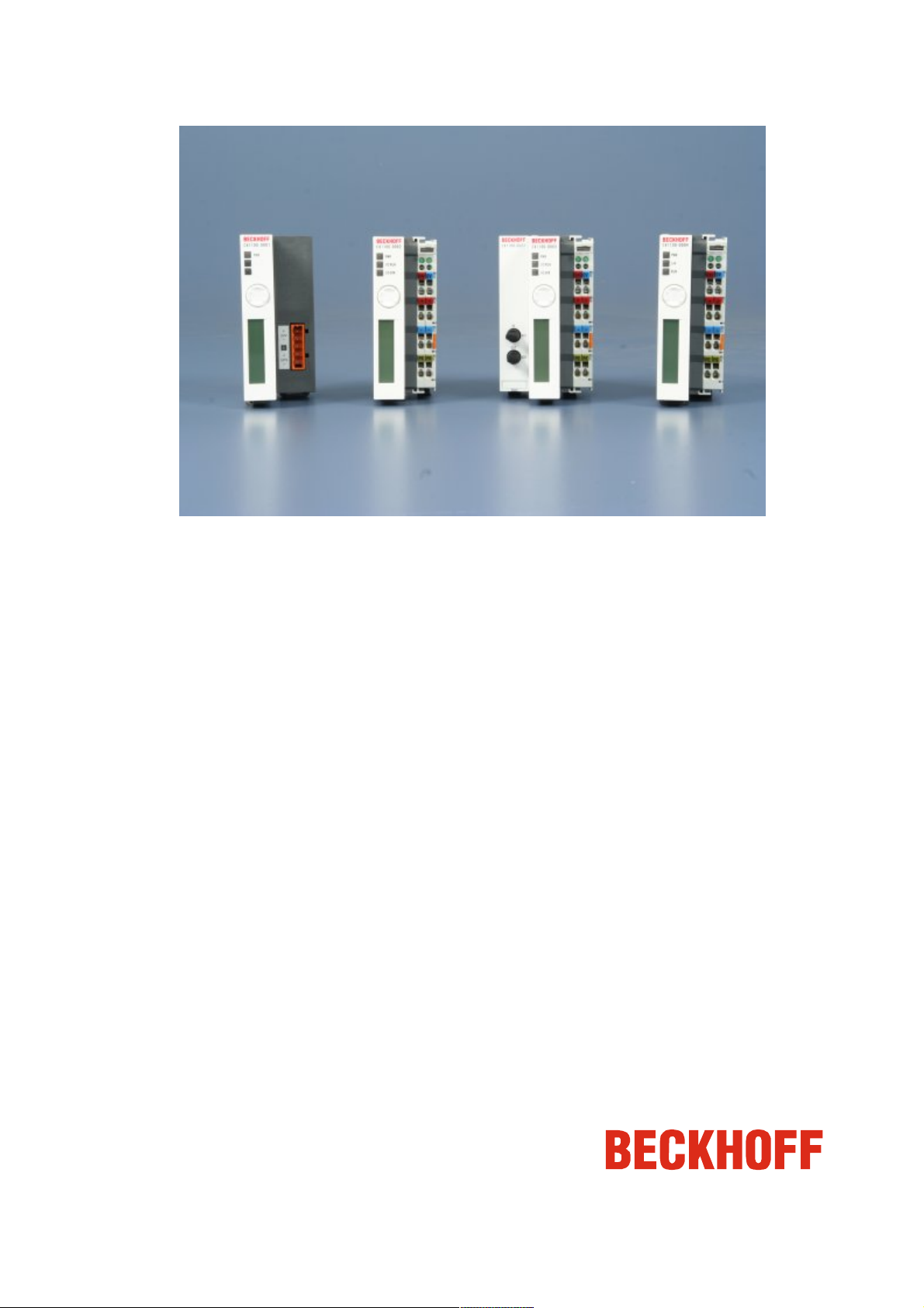
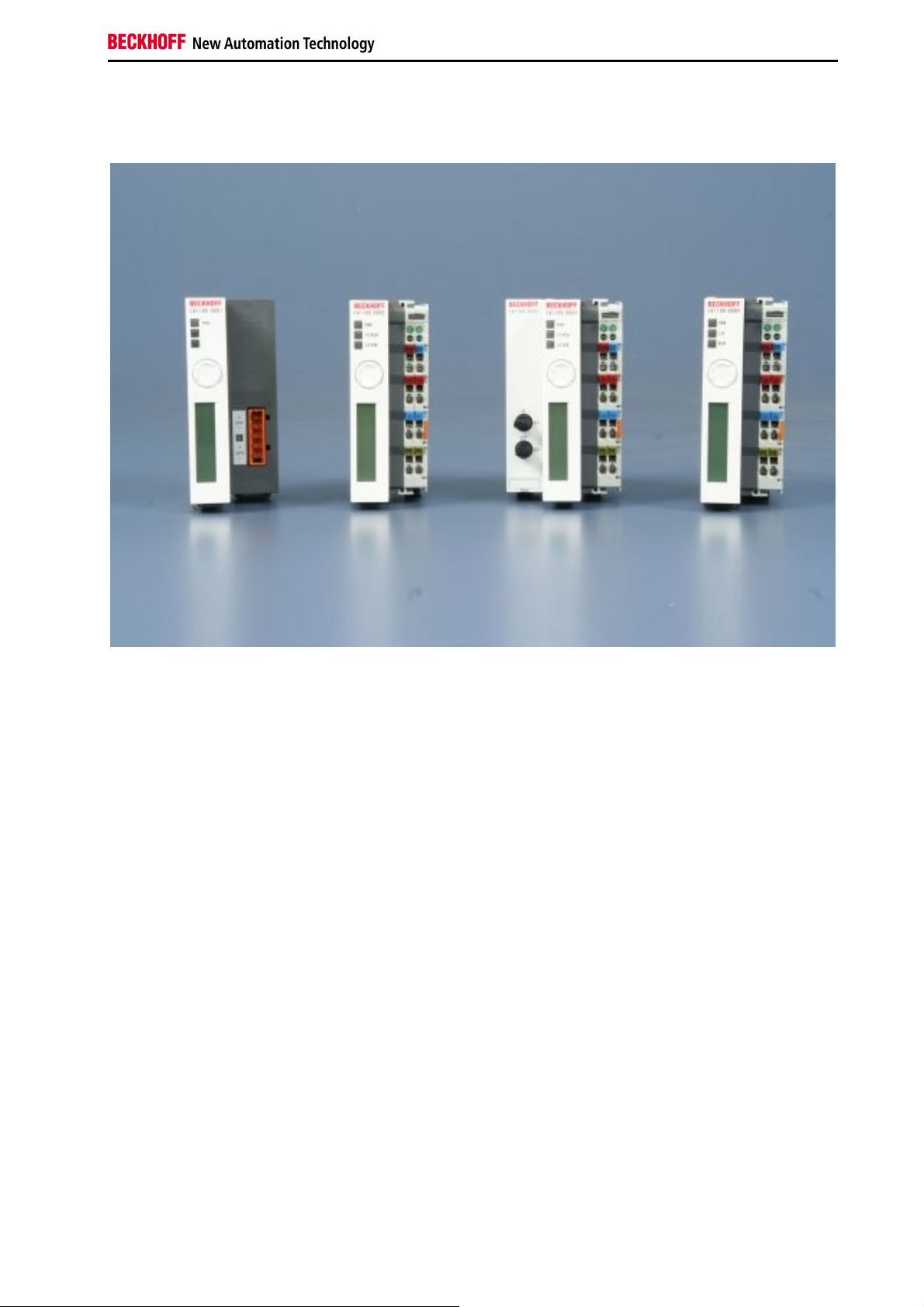
CX1100-000x
power supply units and I/O interfaces
One of four power supply modules can be selected for a CX10x0 system. The power supply of all other system
components is ensured via the internal PC104 bus; no separate supply lines are required. However, the CX1100
components offer further important characteristics that go beyond a pure power supply: an integrated NOVRAM
enables the fail-safe storage of process data, an LCD display with two lines of 16 characters each is used for
displaying system and user messages. Local I/O signals are connected via the CX1100-0002 power supply variant,
to which all Beckhoff Bus Terminals can be connected, or via CX1100-0003, which in addition to the Bus Terminals
enables the connection of Extension Box IExxxx type Beckhoff Fieldbus Box modules. The option to connect Bus
Terminals or Fieldbus Box modules creates a control system with a very variable, expandable I/O level with large
signal variety. The I/O data are stored in a DPRAM, which is accessible by the CPU via the system bus. The power
supplies of the CX system can be changed in the field: If, for example, local I/O via Bus Terminals is required,
CX1100-0001 can be replaced with CX1100-0002 in the field. Local I/O signals are connected via the CX1020 and
the CX1100-0002 power supply variants (Bus Terminals), CX1100-0003 (Bus Terminals
and Fieldbus Box modules via IP-Link) or CX1100-0004 for EtherCAT Terminals. With CX1100-0004 the I/O data are
stored directly in the main memory of the CPU; a DPRAM is no longer required. The CX1100-0004 power supply unit
for EtherCAT Terminals can only be connected in conjunction with the basic CX1020 CPU module.
The technical data are as follows:
CX1100-0001
CX1100-0002
CX1100-0003
CX1100-0004
An overview about architecture with the common system components GCB, ACB, NOVRAM, Display und Taster are
described together in one chapter. Special interfaces are described in the power supply units containing the
Embedded PC 7
Page 10
Product overview
interfaces.
Architecture
Display
Taster
Architecture of the power supply units
The four power supply units for the CX10x0-System accomplish more task than supporting the system with power.
Each module has three basic functions. Additional each model supports different connection to communication
busses. Caused by these different connections the internal architecture differ. At first the common functions are
described.
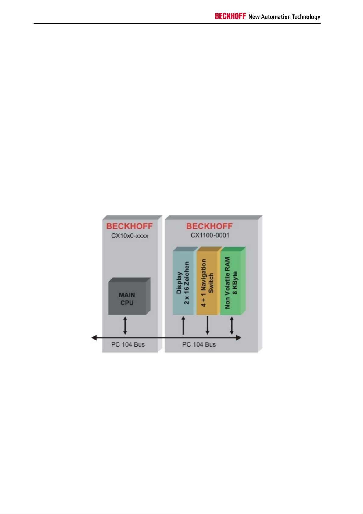
All power supply feature, except for power supply, the following functions:
1. Display 2 x 16 characters
2. 4+1 navigation switch
3. Non Volatile RAM
These functions are managed by the control program via the PC104 bus. The structure of the CX1100-0001 is shown
in the following figure:
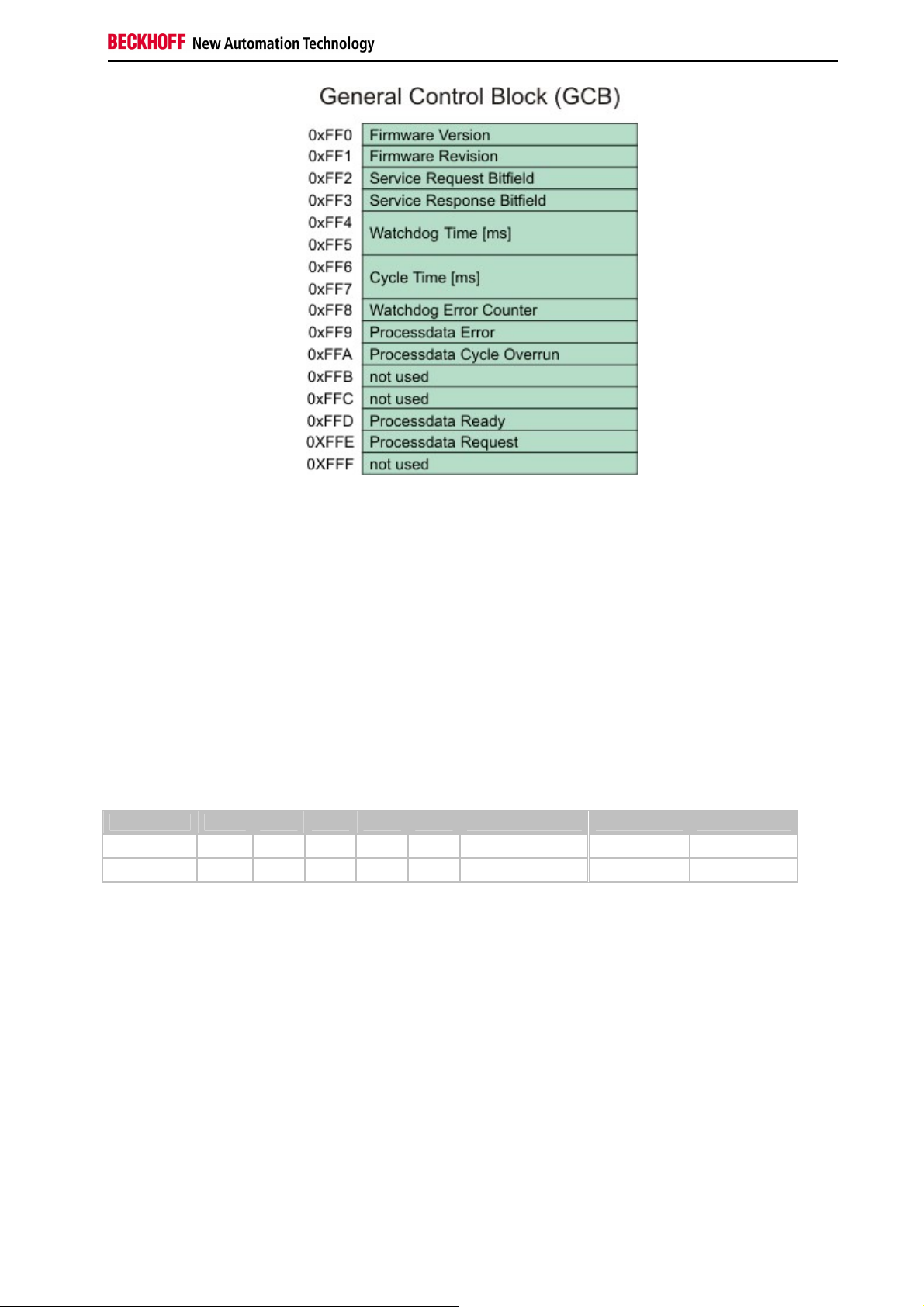
"General Control Block" (GCB)
The top 16 byte of the system control area (starting at the physical hex address D0000 + Offset FF0) form the
general control block GCB, which holds the control byte required to start the I/O processing of the K-Bus and IP-Link.
The CPU of the main module controls the whole architecture. With memory mapped I/O regions data can be
exchanged. The data needed to run the system is combined in the "General Control Block" (GCB). Its base address
is "0xD1000". The figure shows the Data and the offset. Some registers are not needed in all units. So only the
requested registers are mapped other addresses are masked out.
8 Embedded PC
Page 11
Product overview
Firmware Version:
These two bytes contain the hex decimally coded version number of the CX1100 firmware. E.g. the first byte could
show B3(hex): this results in firmware version B3.
Firmware Revision:
These two bytes contain the hex decimally coded revision number of the CX1100 firmware. E.g. the byte could show
00: this results in revision 00.
Service Request / Response Bitfield: (nur für CX1100-0002 / -0003)
These two bytes contain a sequence of bits, by which certain service functions may be executed. The service
function is invoked by setting the appropriate request bit, the controller executes and sets the response bit. Before
the same function can be invoked again, the request bit must be set to zero and wait until the response bit is also set
to zero. An execution error is signaled by raising response bit 7.
Bitfeld Bit 7 Bit 6 Bit 5 Bit 4 Bit 3 Bit 2 Bit 1 Bit 0
Request - - - - - Link Images Remap Reset Node
Response Error - - - - Images Linked Remapped Reset Done
Reset Node:
with this bit, a software reset of the 80C165 microcontroller can be performed. This is different from the hardware
reset which may be performed in the Auxiliary Control Block (ACB).
Remap:
with this bit, the two-byte PLC interfaces normally residing in the input/output process areas can be remapped into
the general control block for K-Bus and IP-Link. Thus the input/output process image areas can be kept clean and for
the sole purpose of storing I/O-data.
Link Images:
if set, this bit links the K-Bus logically to the IP-Link in the case of error occurrence - meaning that if one of them
stops operating, the other one is stopped as well. By default, this bit is set so stopping both I/O systems in case of
error is the standard behavior.
Watchdog Time:
With the request of an I/O cycle through "PD cycle request", a watchdog timer with this specified millisecond time ist
started. If the cycle is not being restarted by a next "PD cycle request", the watchdog elapses and as a consequence
the output process image is zeroed. This resets all outputs to a safe state (OFF). If another value than the default
100ms is written to this cell, a "Reset node" is needed to activate the change.
Embedded PC 9
Page 12
Product overview
Cycle Time:
This is the time elapsed between the initiation and termination of an I/O process image update (K-Bus + IP-Link ).
The time is recorded in units of microseconds and starts with writing a new cycle request to the field "PD cycle
request" and it stops with the termination response in the field "PD cycle ready". For CX1100-0002 this time reflects
the K-Bus update time, for CX1100-0003 it is the sum of K-Bus update time and IP-Link update time.
Watchdog Error Counter:
If the Watchdog Time exceeds the value in this register is increased by one. In this way the user can get the numbers
of watchdog-time errors. (available since firmware revision B6)
Processdata Error:
This byte contains the information on the error status of the I/O blocks. The possible bit codes are:
Bitfeld Bit 7 Bit 6 Bit 5 Bit 4 Bit 3 Bit 2 Bit 1 Bit 0
Processdata Error - - - - - - IP-Link Error K-Bus Error
The bit is set to "TRUE", if an error occurred. If both bits are zero, there is no error on either bus system. Error
recovery may be attempted by invoking the "Reset bus" service in the corresponding CB of either K-Bus or IP-Link.
Processdata Cycle Overrun:
This byte contains a counter, which is incremented each time a new process data cycle is requested although the
previous cycle has not yet completed. This can happen only due to a handshake programming error or if the user
task cycle time is shorter than the time for I/O update.
PD Cycle Ready / PD Cycle Request:
These two bytes contain the request value and the ready value for operating a process data (PD) I/O cycle. The user
program is supposed to write a pattern (e.g. an up-counter value ) to the request byte, thus triggering the I/O cycle.
Once the I/O cycle is finished, the microcontroller will set the ready byte to match the request byte. A new request
can then be written to the request byte.
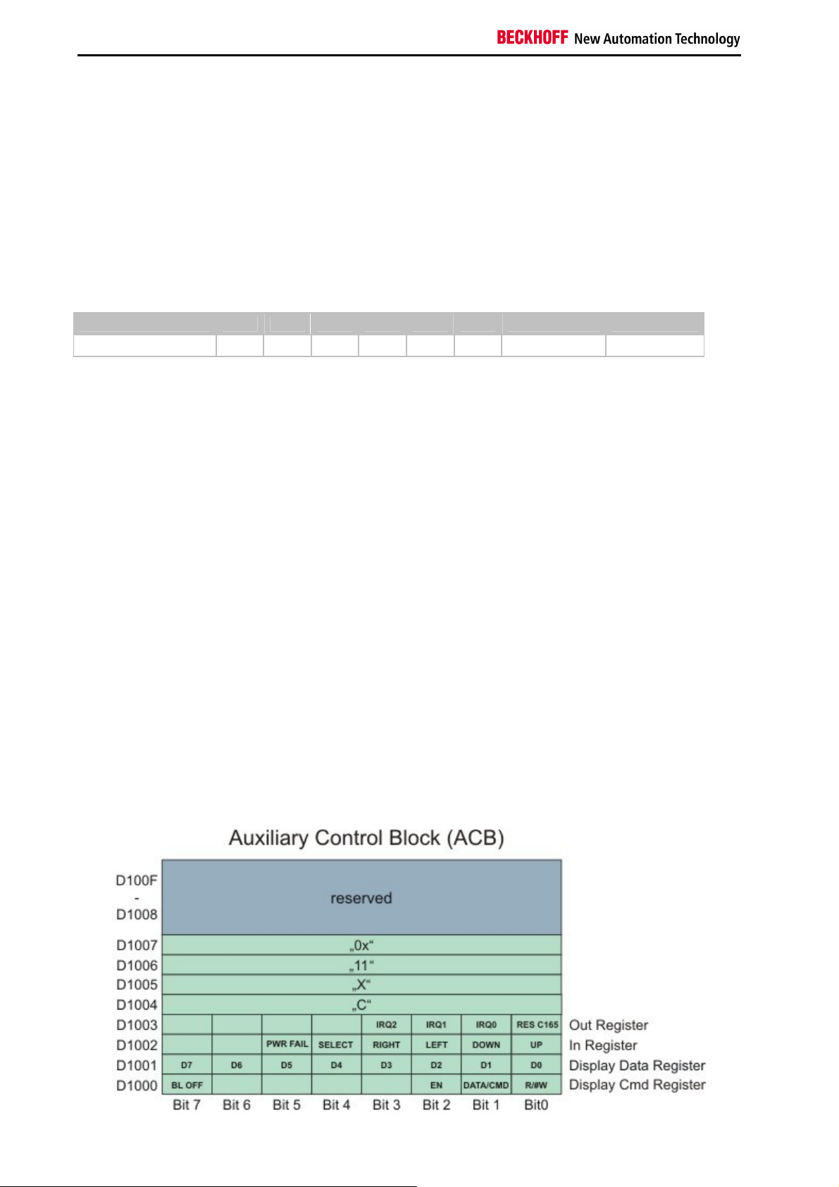
"Auxiliary Control Block" (ACB)
The Auxiliary Control Block of CX1100 is a block of 16 bytes and starts at address D1000 (hex). It is a miscellaneous
control block for controlling:
- the 2x16char FSTN LCD Display
- the navigation switch
- the hardware reset of the 80C165 microcontroller
The following schematic shows the layout of the ACB and is followed by a description of the single bits contained in it.
10 Embedded PC
Page 13

Product overview
Display Cmd Register:
Bit 0 R/#W
Bit 1 DATA/#CMD
Bit 2 EN
Bit 7 BL OFF
R/#W: This bit control the Read or Write operation for programming the display2x16 char LCD display.
DATA/#CMD: This bit controls whether the byte "Display Data Reg" holds a command or display data.
EN: This is the enable bit for executing the operation with the display controller.
BL OFF: If set, this bit turns of the backlight of the LCD Display. This feature may be used for blinking with the
backlight, thus attracting the users attention to an important message on the display. It may also be
used to save power in the case of power loss and UPS operation.
Display Data Register:
These are the data bits for issuing commands or reading/writing data to the display controller. These bits are
operated in conjunction with bits 0,1,2 of the Display Cmd Reg. For more detailed information please refer to the
display controller documentation.
In Register:
These bits reflect the contact status of the 4+1 direction navigation switch on the front side of the CX1100 unit. These
events may be used by a software for implementing a menu driven data input/output together with the LCD display.
Bit 0 UP
Bit 1 DOWN
Bit 2 LEFT
Bit 3 RIGHT
Bit 4 SELECT
Bit 5 PWR-FAIL (reserved for future use - do not use)
An example for access the switch is given in the detailed description of the switch.
Out Register:
Bit 0 RES C165
This bit resets the microcontroller 80C165 and restarts the initialization of the K-Bus and IP-Link circuit. For doing the
reset, this bit must be set high and then set back to low. There is no need for an explicit hold time.
This bit may be used to recover from K-Bus faults such as removing a terminal during operation. It needs to be set at
least once at startup or initialization of the user software before operating the k-Bus.
Bit 1 IRQ0 (reserved for future use - do not enable)
Bit 2 IRQ1 (reserved for future use - do not enable)
Bit 3 IRQ2 (reserved for future use - do not enable)
Memory region 0xD1004 to 0xD1008:
In this region the type of the power supply module is encoded. By adding the four registers the type description is
given:
CX1101 CX1100-0001 power supply unit with display, 4 + 1 navigation switch and NOVRam
CX1102 CX1100-0002 power supply unit with display, 4 + 1 navigation switch, NOVRam and K-bus connection
CX1103 CX1100-0003 power supply unit with display, 4 + 1 navigation switch, NOVRam, K-bus-connection and
IP-Link-connection
CX1104 CX1100-0004 power supply unit with display, 4 + 1 navigation switch, NOVRam and E-bus connectio.
Das Non Volatile RAM
The NOVRAM is one of the most important functions of the power supply unit. The access is realized via the PC104
bus. The mapping to PLC is realized by TwinCAT System Manager. Here needed variables can be defined and
mapped to memory. Further details are given in the TwinCAT documentation.
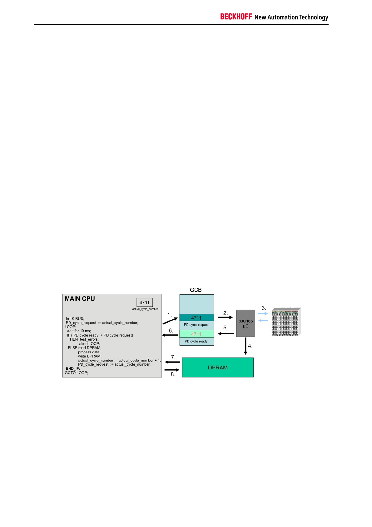
K-BUS and IP-LINK Operation
This section describes how to trigger the K-Bus (and in the case of CX1100-0003 also the I/O-boxes connected to IP-
Embedded PC 11
Page 14
Product overview
Link) in order to read input values and write output values. The procedure is the same for IP-Link, the description
limits itself to K-Bus for textual simplicity.
The I/O operation is done through the bytes named "PD cycle ready" and "PD cycle request" in the GCB. The K-Bus
cycle is triggered by a write operation to the byte "PD cycle request". Although the value being written to this byte
does not matter (it is only the write operation which is important), it is recommendable write a counter-up value to this
byte. The microcontroller for the K-Bus will react to the write operation by performing a K-Bus cycle and gathering the
I/O data. Once the cycle is completed and the electrical signal input data are written to the DP-RAM, the
microcontroller will set the content of byte "PD cycle ready" equal to the content of "PD cycle request", thus signaling
the completion of the I/O cycle. The time required to run a K-Bus cycle depends on the number of terminals attached
to CX1100: it is minimum 700 microseconds and typically well below 5 milliseconds. The K-Bus cycle time can be
viewed by using the TwinCAT System Manager tool, by entering the exact terminal configuration.
At startup of the user program, before going into cyclic operation, it is mandatory to reset the K-Bus controller by
triggering the "RES C165" bit in the Auxiliary Control Block section of CX1100. Please refer to the description of the
ACB for how to do this.
The sequence of operating the K-Bus can be explained by assuming a cyclic automation task executed each 10 ms
on the main CX1000 CPU:
Task cycle "n":
- check if K-Bus operation of previous cycle has finished: is "PD cycle ready" = "PD cycle request" ? Proceed if yes,
issue error message and abort cyclic task operation if not, because a K-Bus cycle does not need 10 milliseconds to
finish !
- read the input data from the DP-RAM (these are the input data gathered by the previous cycle "n-1" )
- write the output data to the DP-RAM (these are the outputs calculated by the previous cycle "n-1" ).
- increment and write the new value to "PD cycle request"
- perform task user code
Task cycle "n+1":
- check if K-Bus operation of previous cycle has finished: is "PD cycle ready" = "PD cycle request" ? Proceed if yes,
issue error message and abort cyclic task operation if not, because a K-Bus cycle does not need 10 milliseconds to
finish !
- read the input data from the DP-RAM (these are the input data gathered by the previous cycle "n" )
- write the output data to the DP-RAM (these are the outputs calculated by the previous cycle "n" ).
- increment and write the new value to "PD cycle request"
- perform task user code
Of course only the I/O bytes needed should be copied to or from the DP-RAM, since each read or write operation
over PC104 is time consuming. Please note that the terminal outputs need a K-Bus refresh no later than 100
milliseconds, otherwise the watchdog in each terminal will shut off the outputs. This means that the task cycle time
should be below 100 milliseconds. Also, if more than one cyclic automation task needs access to K-Bus I/O, it is
important that only one task operates the K-Bus and the other tasks implement an I/O buffering in order to have a
consistent I/O image. In this scenario, the task with the highest priority has the shortest cycle time and will trigger the
K-Bus.
Please note also that it is assumed that in each cycle the integrity of the K-Bus is being checked by examining the
"Processdata error" field in the GCB. Cyclic operation should be aborted in the case of an I/O error and user should
be prompted for corrective actions. Cyclic operation can be resumed after resetting the faulty bus over the service
request fields of the control block.
12 Embedded PC
Page 15
Product overview
Adapter RAM Hardware address overview
available memory addresses CX1020: D0000-DFFFF (hex)
Base Address
(hex)
D0000 D0FFF 1000 R/W CX1100-0002/3 Dual Ported RAM
D1000 D100F 10 R/W CX1100 Auxiliary Control Block( LCD
D1010 D101F 10 R/W CX1100-0900 UPS Control Block
D2000 D3FFF 2000 R/W CX1100 Non Volatile RAM
D4000 D5FFF 2000 R/W CX1500-M310 Profibus Master DPRAM
D6000 D7FFF 2000 R/W CX1500-M510 CANopen Master
D8000 D9FFF 2000 R/W CX1500-M520 DeviceNet Master
DA000 DBFFF 2000 R/W CX1500-M200 Lightbus Master DPRAM
DC000 DDFFF 2000 R/W CX1500-M750 Sercos Master DPRAM
For some fieldbus connections (all Slave modules) the base addresses are mapped in the memory region upper
DFFFF(hex). So this modules must be ordered with other base addresses. The same situation takes place if more
than two or more master modules of same type are used (for more see note below). The order numbers for the
modules are:
order number alternative ISA-Adresse
Master connection
CX1500-Mxxx-0001 D4000
CX1500-Mxxx-0002 D6000
CX1500-Mxxx-0003 D8000
CX1500-Mxxx-0004 DA000
CX1500-Mxxx-0005 DC000
Slave connection
CX1500-Bxxx-0001 D4000
CX1500-Bxxx-0002 D6000
CX1500-Bxxx-0003 D8000
CX1500-Bxxx-0004 DA000
CX1500-Bxxx-0005 DC000
Replace xxx with the following number for the requested fieldbus system:
End Address
(hex) Size(Bytes)(hex)
Access
Type Description
Display, misc. registers)
DPRAM
DPRAM
200 for Lightbus
310 for Profibus
510 for CAN-open
520 for DeviceNet
750 for Sercos (only Master connection available)
Note
Two connection modules (master or slave) can be used simultaneously.
If more than two connections are needed call Beckhoff Automation GmbH for further information.
Embedded PC 13
Page 16
Product overview
Display
Display setup
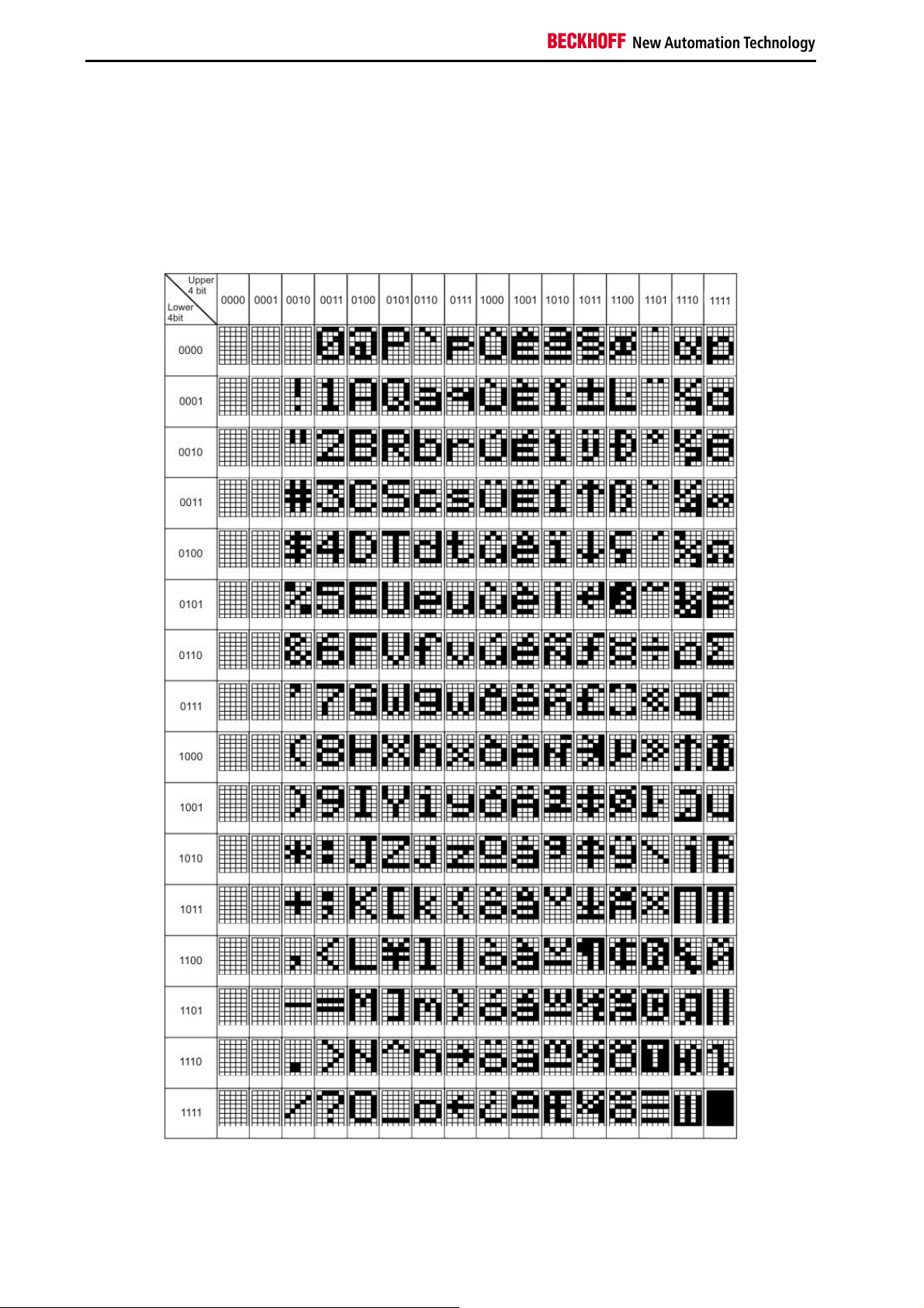
The display built-in the CX1100-000x units, is a LCD display. It features 2 lines with 16 characters. Each character
has a resolution of 5 x 8 pixel. The font is named SPLC780C-11 and is fixed. The following figure shows the the font
with all available characters.
For easy reading a background illumination is integrated to the display. The illumination can be switch on and off.
This blinking can be used to attract the user in certain situations. The state can be set via the controller. The
controller reads the registers in "Auxiliary Control Block" and addresses the display in the desired manner.
14 Embedded PC
Page 17
Product overview
Representing text on the display
The display can be controlled in two ways with the aid of TwinCAT. One version is programming through the System
Manager. A second possibility is for the display to be written by a function block directly from the PLC program.
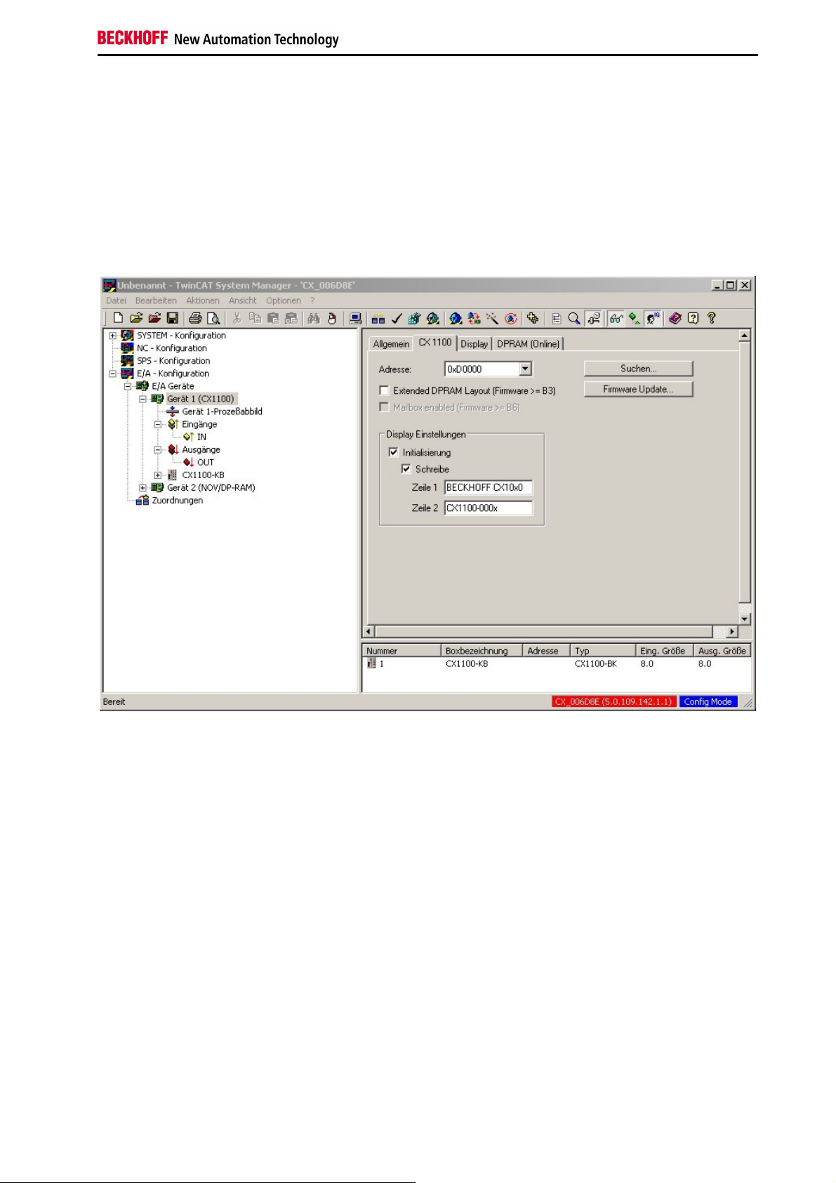
Settings in the System Manager
When the TwinCAT system starts, the text specified in the configuration can be written to the display. This text is set
in the System Manager.
This is done by selecting the CX10x0 device in the hierarchy browser. Under the CX1100 tab it is possible to write
both lines of the display in the "Display settings" area. This requires the fields at the location for initialisation and
writing to be selected. The changes only take effect after the configuration has been written. When TwinCAT restarts,
the set text is then displayed.
Embedded PC 15
Page 18
Product overview
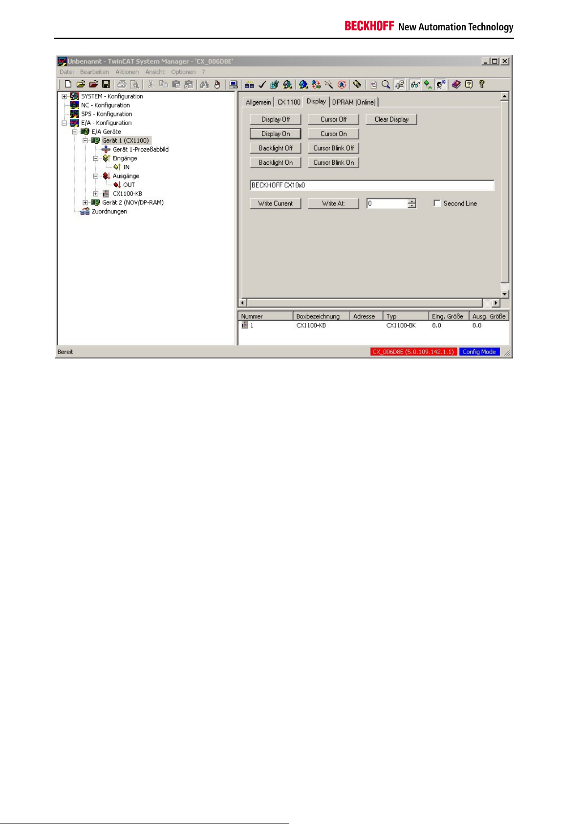
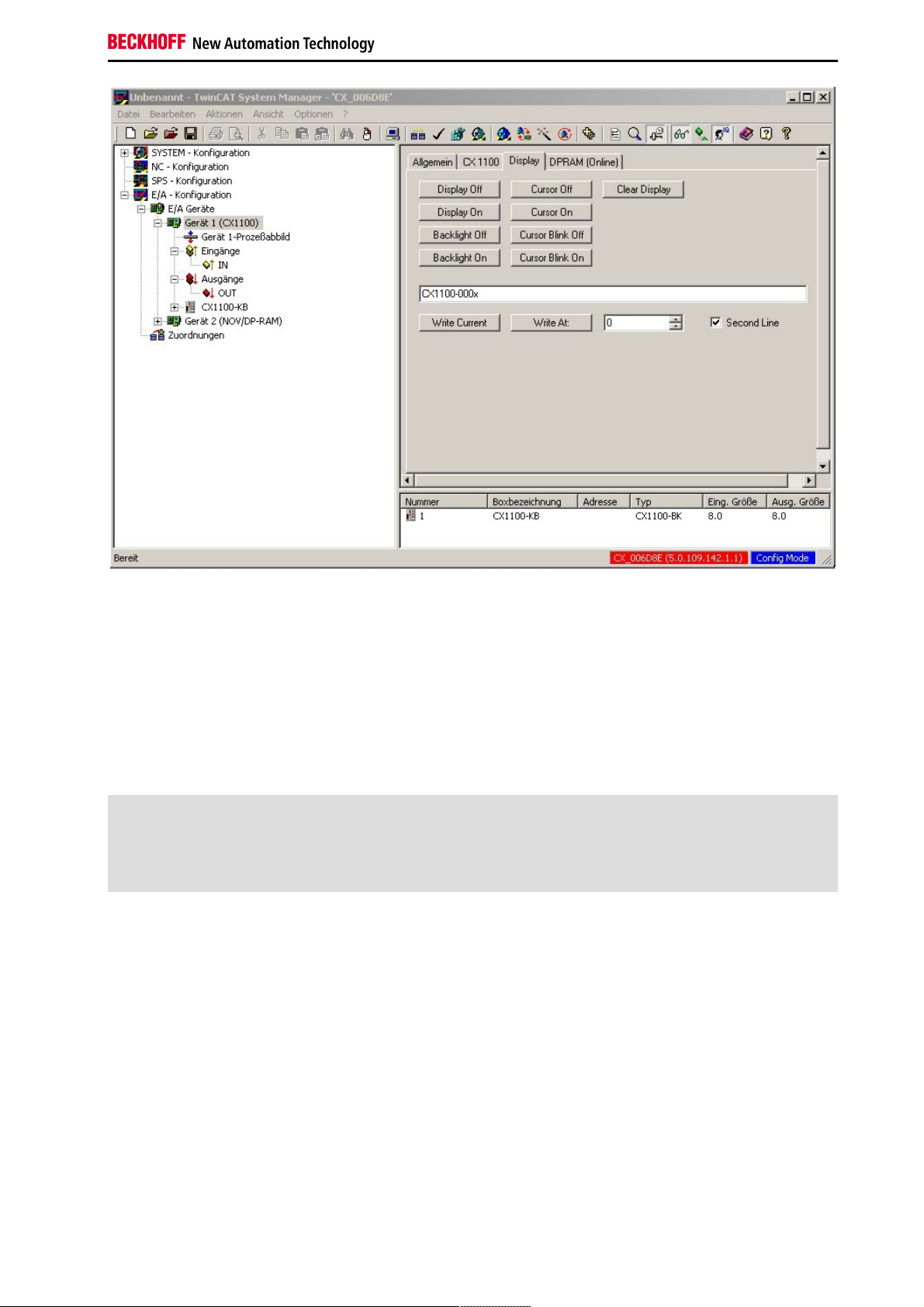
The display can be controlled directly through the Display tab. The corresponding functions are carried out
immediately through the switches. It is possible to execute the following functions:
Switch the display on/off (text is displayed/hidden)
Background illumination on/off
Clear the display (text is cleared, and must be re-entered)
Cursor on/off (the cursor is displayed)
Cursor flash on/off (the cursor flashes)
The desired text is entered into the text input field. The "Write current" switch inserts the text at the current position of
the cursor.
16 Embedded PC
Page 19
Product overview
Using the "Write At" switch, the numerical input box and the "Second Line" check box, it is possible to write to a
specified position on the display. The useful range of values for the position extends from 0 to 15. The user should
also, however, consider the length of the text. (Each line has 16 characters!) In the example illustrated below, the text
"CX1100-000x" is written to Position 0 (the start of the line) on Line 2.
Settings in the PLC program
The function block FB_CX1000SetTextDisplay is provided in the library for the CX family (TcCX1000System.lib) in
order to operate the display from a PLC program. All the functions of the display can be manipulated from this
function block. The library must, however, be integrated through the library administrator. If this has been done, the
block is available as a function block. It is instanced as such in the declarations part of the program.
PROGRAM MAIN
VAR
Display_0 : FB_CX1000SetTextDisplay;
END_VAR
It is then called from the program with its parameters. There are five parameters for this function block:
bExecute : BOOL
nDevID : UDINT
nMode : E_CX1000_DisplayModes
stLine : STRING(20)
nCursorPos : DWORD
The command is executed in response to a rising edge at "bExecute". "nDevID" provides the Device ID of the
CX1100 that is to be written to. The ID is displayed in the System Manager. (The General tab for the CX1100, top
right). The parameter "stLine" is used to pass a text of at most 20 characters. Only the first 16 of these characters,
however, will be displayed. The writing position of the text uses quoted through "nCursorPos". 0 to 15 is a useful
range for this value. "nMode" selects the operating mode of the function block. The modes are:
e_CX1000_DisplayNoAction : No action.
e_CX1000_DisplayOn : Switch on the display.
Embedded PC 17
Page 20

Product overview
e_CX1000_DisplayOff : Switch off the display.
e_CX1000_CursorOn : Switch on the cursor.
e_CX1000_CursorOff : Switch off the cursor.
e_CX1000_CursorBlinkOn : Switch on the cursor flashing.
e_CX1000_CursorBlinkOff : Switch off the cursor flashing.
e_CX1000_BackLightOn : Switch on the background illumination.
e_CX1000_BackLightOff : Switch off the background illumination.
e_CX1000_ClearDisplay : Clear the content of the screen.
e_CX1000_WriteLine1 : Write to the first line.
e_CX1000_WriteLine1 : Write to the second line.
The call then looks like this:
Display_0(
bExecute := write_now, (*write_now is a bool, function: switch)
nDevID := 1, (*DeviceID of the CX1100*)
nMode := e_CX1000_WRITELine1, (*Write to the first line of the display*)
stLine := 'Beckhoff CX1100', (*Fixed text or variable*)
nCursorPos := 0 (*Writing position, e.g. 0 for start line*)
);
The block supplies a few status signals for evaluating the program environment. These can be used to provide
feedback to the PLC program. There are three response signals from the function:
bBusy : BOOL
bErr : BOOL
nErrorID : UDINT
"bBusy" indicates that the command is at present being transferred by ADS. No new command will be accepted as
long as "bBusy" remains TRUE. "bErr" reports an error in a call to a function block. (The signal becomes TRUE).
"nErrorID" permits the error that has occurred to be analysed by means of an error number. The error number refers
to an error in the ADS protocol.
18 Embedded PC
Page 21

Product overview
LCD Display
The LCD display of the power supply units has two rows of 16 characters each and is used for displaying system and
user messages.
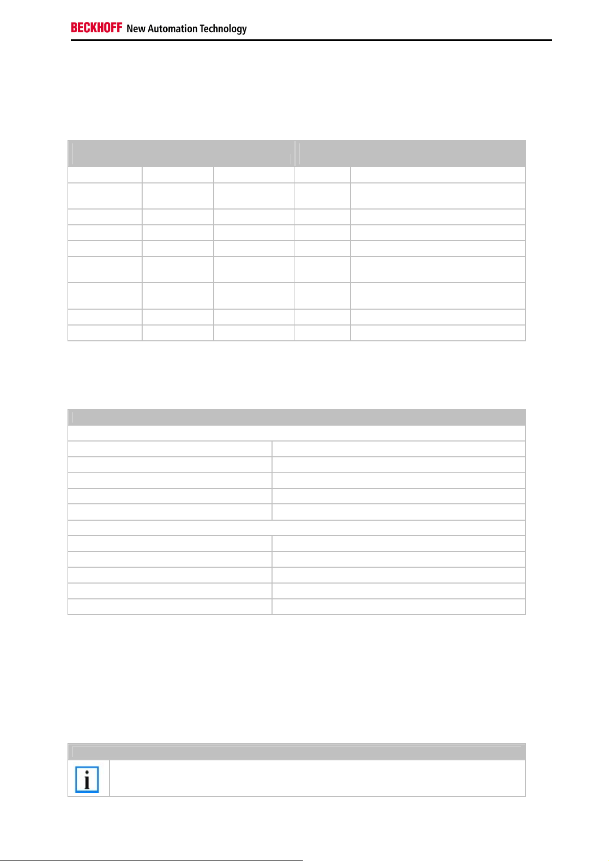
"Index-Group/Offset" Specification for the LCD Display
ADS Port 300
Index
Group
0x00005000
+ DeviceID
0x00005000
+ DeviceID
0x00005000
+ DeviceID
0x00005000
+ DeviceID
0x00005000
+ DeviceID
0x00005000
+ DeviceID
0x00005000
+ DeviceID
0x00005000
+ DeviceID
0x00005000
+ DeviceID
0x00005000
+ DeviceID
Data
Index Offset Access
0xFFFF90FF R&W Cursor OFF
0xFFFF91FF R&W Cursor ON
0xFFFF92FF R&W Cursor blink
0xFFFF93FF R&W Cursor blink ON
0xFFFF94FF R&W Display OFF
0xFFFF95FF R&W Display ON
0xFFFF96FF R&W Backlight OFF
0xFFFF97FF R&W Backlight ON
0xFFFFA0FF R&W Write Text line 1
0xFFFF00FF R&W Write Text line 2
type
Phys.
unit
Def.
range
Description Remarks
OFF
Embedded PC 19
Page 22

Product overview
4 + 1 navigation switch
Operating principle of the switch
The CX1100-000x power supply units all have 4 + 1 navigation switches. The switches can therefore be used to input
five basic states:
1. UP
2. DOWN
3. LEFT
4. RIGHT
5. SELECT
Combined inputs, such as UP + RIGHT or UP + RIGHT + SELECT can also be entered. The values of the switches
are stored in a register of the "Auxiliary Control Block", ACB. Details may be referred to in the architectural
description.
The register can be accessed from within a PLC program, and the value can be assessed. This requires a variable of
type USINT first to be created in the PLC program. This is then linked in the TwinCAT System Manager to the INregister of the CX1100.
The figure shows the linked signals (with a bright red background). The switch can be accessed from the PLC
program through the Switch variable. The PLC program takes the form described below. To begin an external
variable is declared as an input. (In this example it is at address 0)
20 Embedded PC
Page 23

Product overview
PROGRAM MAIN
VAR
Taster AT %IB0 : USINT;
END_VAR
A simple CASE statement can then be used to evaluate the switch, and the desired function can be initiated, e.g.:
CASE Taster OF
0: ACTION := NONE;
1: ACTION := UP;
2: ACTION := DOWN;
4: ACTION := LEFT;
8: ACTION := RIGHT;
16: ACTION := SELECT;
END_CASE;
In this case, "ACTION" is a newly defined ENUM type. It is also possible for the desired action to be activated
immediately.
The sum of the numerical values is used for the combined functions. In other words, UP (1) and RIGHT (8) would be
8 + 1 = 9. In this way, only sensible combinations are possible. In other words, switch positions that are opposite to
one another cannot be selected without damaging the switch.
If the programmer does not want to carry out the evaluation, the TwinCAT System provides a library function that
implements conversion of the switch input into an ENUM type. For this purpose, the library for the CX Systems,
TcSystemCX.lib, must be integrated into the library manager. The function is called "F_CXNaviSwitch(iCX1100_IN :
USINT)", and returns an ENUM type. This encodes the direction of the switch that has been pressed as names, for
example e_CX1100_NaviSwitch_MIDDLE for <Middle>. The full list of valid possibilities is:
e_CX1100_NaviSwitch_IDLE
e_CX1100_NaviSwitch_MIDDLE
e_CX1100_NaviSwitch_TOP
e_CX1100_NaviSwitch_TOPRIGHT
e_CX1100_NaviSwitch_RIGHT
e_CX1100_NaviSwitch_BOTTOMRIGHT
e_CX1100_NaviSwitch_BOTTOM
e_CX1100_NaviSwitch_BOTTOMLEFT
e_CX1100_NaviSwitch_LEFT
e_CX1100_NaviSwitch_TOPLEFT
e_CX1100_NaviSwitch_MIDDLE_TOP
e_CX1100_NaviSwitch_MIDDLE_TOPRIGHT
e_CX1100_NaviSwitch_MIDDLE_RIGHT
e_CX1100_NaviSwitch_MIDDLE_BOTTOMRIGHT
e_CX1100_NaviSwitch_MIDDLE_BOTTOM
e_CX1100_NaviSwitch_MIDDLE_BOTTOMLEFT
e_CX1100_NaviSwitch_MIDDLE_LEFT
Embedded PC 21
Page 24

Product overview
e_CX1100_NaviSwitch_MIDDLE_TOPLEFT
Further details on the function can be read in the TwinCAT documentation. The function can be used in a program as
follows: (The declaration and linking are as given in the example above)
CASE F_CXNaviSwitch(Taster) OF
e_CX1100_NaviSwitch_IDLE :; (* do nothing *)
e_CX1100_NaviSwitch_MIDDLE :call_select; (* select item *)
e_CX1100_NaviSwitch_TOP :call_prev_item; (* previous menue item *)
e_CX1100_NaviSwitch_RIGHT :call_inc_value; (* increase value *)
e_CX1100_NaviSwitch_BOTTOM :call_next_item; (* next menue item *)
e_CX1100_NaviSwitch_LEFT :call_dec_value; (* decrease value *)
END_CASE;
Further evaluation of the switch inputs is then done later in the program.
22 Embedded PC
Page 25

Product overview
CX1100-0001
CX1100-0001 connections
This power supply unit does not have an I/O interface. The power supply is therefore connected through the 5-pin
open pluggable connector. The power supply unit supplies all further system components with a voltage of 24 V DC (15 %/+20%) via the PC104 bus. The dielectric strength of the power supply unit is 500 V
The integrated NOVRAM permits storage of process data that is safe against power failure.
rms
.
Pin Allocation Open Style Connector:
Pin Assignmnet
1 +24 V DC
2 0 V DC
3 GROUND
4 reserved / don't use
5 reserved / don't use
LED:
With proper connection of the power supply unit and with power supply turned on, the power LED (PWR) lights up
green. In the case of a short-circuit, it lights up red.
Embedded PC 23
Page 26

Product overview
Technical data CX1100-0001
dimensions:
One of power supply modules can be selected for a CX10x0 system. The power supply of all other system
components is ensured via the internal PC104 bus; no separate supply lines are required. However, the CX1100
components offer further important characteristics that go beyond a pure power supply: an integrated NOVRAM
enables the fail-safe storage of process data, an LCD display with two lines of 16 characters each is used for
displaying system and user messages.
The power supply CX1100-N001 has no I/O interfaces.
Technical data CX1100-0001
Power supply 24 V DC (-15%/+20%)
Dielectric strength 500 V
Max. power consumption 2.5 W
Recommended fuse at 24 V 4 A
K-bus connection -
E-bus connection -
IP-Link connection -
K-bus power supply to -
connection type 1 x Open Pluggable Connector, 5-pin
NOVRAM 8 kByte
Display FSTN display 2 lines x 16 characters of text, illuminated
I/O-DPRAM -
Diagnose LED 1 x PWR
Dimensions (W x H x D) 45 mm x 100 mm x 91 mm
weight app.180 g
operating/storage temperature 0° C ... +55° C / -25° C ... +85° C
Relative humidity 95% no condensation
Vibration/shock resistance conforms to EN 60068-2-6 / EN 60068-2-27/29
EMC resistance burst / ESD conforms to EN 61000-6-2 / EN 61000-6-4
protection class IP 20
(supply / internal electronics)
eff
24 Embedded PC
Page 27

Product overview
Architecture of power supply CX1100-0001
This power supply features, except for power supply, the following functions:
1. Display 2 x 16 characters
2. 4+1 navigation switch
3. Non Volatile RAM
These functions are managed by the control program via the PC104 bus. The structure of the CX1100-0001 is shown
in the following figure:
This power supply unit features only the basic functions. These functions are described in the architecture overview.
Embedded PC 25
Page 28

Product overview
CX1100-0002
CX1100-0002 connections
This power supply unit is equipped with an I/O interface, which permits connection of the Beckhoff Bus Terminals.
The power is supplied via the upper spring-loaded terminals labelled “24V” and “0V”.
The supply voltage feeds the CX system and supplies a voltage of 24 V DC (-15 %/+20%) to the Bus Terminals via
the K-Bus. The dielectric strength of the power supply unit is 500 V
on, a further power supply is necessary for the Bus Terminals. This is provided by means of the power contacts,
which are not connected to the power supply.
The integrated NOVRAM permits storage of process data that is safe against power failure.
. Since the K-Bus does no more than pass data
rms
LED:
With proper connection of the power supply unit and with power supply turned on, the power LED (PWR) lights up
green. In the case of a short-circuit, it lights up red.
The I/O LEDs display the operation status of the Bus Terminals. Error-free start-up of the configuration is signalled by
the red "I/O ERR" LED being extinguished. If the ”I/O ERR" LED blinks, an error in the area of the terminals is
indicated. The error code can be determined from the frequency and number of blinks.
PE power contacts
The ”PE" power contact must not be used for other potentials.
26 Embedded PC
Page 29

Technical data CX1100-0002
dimensions:
Product overview
Technical data CX1100-0002
Power supply 24 V DC (-15%/+20%)
Dielectric strength 500 V
Max. power consumption 3.5 W
Recommended fuse at 24 V 4 A
K-bus connection yes (adapter terminal)
E-bus connection -
IP-Link connection -
K-bus power supply to 1.75 A
connection type Cage-Clamp (adapter terminal)
NOVRAM 8 kByte
Display FSTN display 2 lines x 16 characters of text, illuminated
I/O-DPRAM 2 kByte
Diagnose LED 1 x PWR, 1 x I/O Run, 1 x 1/O Err
Dimensions (W x H x D) 40 mm x 100 mm x 91 mm
weight app.250 g
operating/storage temperature 0° C ... +55° C / -25° C ... +85° C
Relative humidity 95% no condensation
Vibration/shock resistance conforms to EN 60068-2-6 / EN 60068-2-27/29
EMC resistance burst / ESD conforms to EN 61000-6-2 / EN 61000-6-4
protection class IP 20
(supply / internal electronics)
eff
Embedded PC 27
Page 30

Product overview
Architecture of power supply CX1100-0002
This power supply features, except for power supply, the following functions:
1. Display 2 x 16 characters
2. 4+1 navigation switch
3. Non Volatile RAM
4. K-bus connections
These functions are managed by the control program via the PC104 bus. The structure of the CX1100-0002 is shown
in the following figure:
This power supply unit features the basic functions. These functions are described in the architecture overview.
Further the k-bus is supported. The access to the bus is managed by a 4 KB dual-ported-RAM (DPRAM). A
microcontroller (80C165) manages the data transfer to the k-bus. The DPRAM is accessed by the CPU (via PC104
bus) and the microcontroller. The following figure shows the memory setup of the DPRAM:
28 Embedded PC
Page 31

Product overview
The memory image of the K-bus resides in the lower memory region (D000 to D0400). This region separates in input
and output region. Since firmware version ≥ B3 it is possible to shift the I/O regions. In this way the process image
can be adapted to the needed space. To each I/O-region the is a control block. Each block consists of 8 byte for
diagnosis purpose. These regions can be shifted, too. The following table shows the structure of the interface. The
offset addresses are default values.
Legacy PLC interface (inputs)
Offset default
0x1F8 [2] diagnosis CX1100-0002 to K-Bus
0x1FA [2] 2 Byte PLC Interface CX1100-0002 to K-Bus
0x1FC [4] reserved
Legacy PLC interface (outputs)
Offset default
0x3F8 [2] diagnosis K-Bus to CX1100-0002
0x3FA [2] 2 Byte PLC Interface K-Bus to CX1100-0002
0x3FC [4] reserved
Embedded PC 29
Page 32

Product overview
The K-Bus Control Block (CB K-Bus)
This section describes the layout of the control block for the K-bus portion of a CX1100-0002 or CX1100-0003. This
control block is located in the memory just below the General Control Block GCB.
CB K-Bus
Offset Default
0xFD0[2] K-Bus 2 byte plc interface to CX1100-0002/3
0xFD2[2] K-Bus 2 byte plc interface from CX1100-0002/3
0xFD4[2] K-Bus diagnosis to CX1100-0002/3
0xFD6[2] K-Bus diagnosis from CX1100-0002/3
0xFD8 K-Bus service request bitfield
0xFD9 K-Bus service response bitfield
0xFDA K-Bus error code
0xFDB K-Bus error argument
0xFDC[2] K-Bus base ptr Inputs 0x000
0xFDE[2] K-Bus base ptr Outputs 0x200
0xFE0-0xFE1 K-Bus cycle count
0xFE2-0xFE3 K-Bus cycle time [µs]
0xFE4 K-Bus bus status
0xFE5-0xFEE Reserved
0xFEF Retry counter
K-Bus 2 byte plc interface to CX1100-0002/3 / K-Bus 2 byte plc interface from
CX1100-0002/3
These two bytes for each direction - from the main CPU to CX1100 and back - special communication with the
register model of the I/O microcontroller. Through this interface, a communication to K-Bus terminals can take place.
The so called register model description can be found in the hardware description manuals of the terminals and bus
couplers. This communication is typically used for extended diagnosis or configuration of terminals if they need to
deviate from the delivery standard, e.g. changing the baud rate for RS232-terminals or gain/offset values with analog
terminals.
K-Bus diagnosis to CX1100-0002/3 / K-Bus diagnosis from CX1100-0002/3
With these two bytes in each direction it is possible to retrieve diagnostic information from the attached terminals.
Since the same diagnostic information is reflected in the process image input area per each terminals, there is in
general no need to use this interface.
K-Bus service request bitfield / K-Bus service response bitfield
IThese two bytes contain a sequence of bits, by which certain service functions may be executed. The service
function is invoked by setting the appropriate request bit, the controller executes and sets the response bit. Before
the same function can be invoked again, the request bit must be set to zero and wait until the response bit is also set
to zero. An execution error is signaled by raising response bit 7.
Bitfeld Bit 7 Bit 6 Bit 5 Bit 4 Bit 3 Bit 2 Bit 1 Bit 0
Request - - - - - - Free Run Reset Bus
Response Error - - - - - Free Run Active Reset Done
Reset Bus:
with this bit, a reset of the K-Bus may be performed. This is necessary after the occurrence of an error (detected by
examination of the "Processdata error"-byte in the GCB) e.g. after a terminal has been pulled out. After performing
the K-Bus reset, the error code and error argument may be read from the locations "K-Bus error code" and "K-Bus
error argument" in the CB K-Bus. If there is no error after reset, the K-Bus is ready for operation again.
30 Embedded PC
Page 33

Product overview
Free Run:
not implemented. Reserved for future use..
K-Bus error code K-Bus error argument
If the K-Bus operation fails (bad terminal, missing end-terminal, severe EMC interference), an error flag is raised in
the GCB and after a K-Bus reset, these two bytes contain the error code and error argument of the occurred fault - if
it still persists.
K-Bus base ptr Inputs / K-Bus base ptr Outputs
These two byte values contain the starting offset for the K-Bus input and output process image area. In most cases
the default offsets should be left unchanged. When changing one of these offsets, a "Remap" or "Reset node" in the
GCB service is needed. Also care must be taken not to overlap with the IP-Link process image area, because in the
CB IP-Link the offset pointers for these areas may also be changed. The Beckhoff automation software TwinCAT
makes use of this base ptr feature and compacts the I/O images in the best way possible.
K-Bus cycle count
This two-byte counter is incremented with each I/O-cycle.
K-Bus cycle time
This is the time elapsed between the initiation and termination of an I/O process image update (K-Bus + IP-Link ).
The time is recorded in units of microseconds and starts with writing a new cycle request to the field "PD cycle
request" and it stops with the termination response in the field "PD cycle ready", in case of CX1100-0002. In case of
CX1100-0003, this time reflects only the K-Bus portion of the total I/O time.
K-Bus bus status
This byte value can take only two states:
1. Byte = 0 → K-bus is ok
2. Byte ≠ 0 → K-bus fault
This information is also reflected in the "Processdata error" field (bit0) of the GCB.
Retry counter
This is a retry counter which is incremented each time the microcontroller needs to redo a cycle because of a
communication error. This counter can be used for judgment of the K-Bus signal quality.
Embedded PC 31
Page 34

Product overview
CX1100-0003
CX1100-0003 connections
This power supply unit permits not only the connection of the Beckhoff Bus Terminals, but also the serial connection
of the Beckhoff fieldbus box modules of the type extension box IExxxx. The power is supplied via the upper spring-
loaded terminals labelled “24V” and “0V”.
The supply voltage feeds the CX system and, over the K-Bus, the Bus Terminals. Since the K-Bus does no more
than pass data on, a further power supply is necessary for the Bus Terminals. This is provided by means of the
power contacts, which are not connected to the power supply.
Fieldbus connection:
Plug the IP link connector into the respective connections, i.e. one fibre-optic cable each into IN (x03) and OUT (x04).
You then connect the other end with the corresponding IP link interface of the extension box. The connection must be
made so that the output of the fieldbus connection is connected to the input of the extension box and vice versa.
LED:
With proper connection of the power supply unit and with power supply turned on, the power LED (PWR) lights up
green. In the case of a short-circuit, it lights up red. The I/O LEDs display the operation status of the Bus Terminals.
Error-free start-up of the configuration is signalled by the red "I/O ERR" LED being extinguished. If the ”I/O ERR" LED
blinks, an error in the area of the terminals is indicated. The error code can be determined from the frequency and
number of blinks.
PE power contacts
The ”PE" power contact must not be used for other potentials.
32 Embedded PC
Page 35

Technical data CX1100-0003
Product overview
Technical data CX1100-0003
Power supply 24 V DC (-15%/+20%)
Dielectric strength 500 V
Max. power consumption 4 W
Recommended fuse at 24 V 4 A
K-bus connection yes (adapter terminal)
E-bus connection -
IP-Link connection yes
K-bus power supply to 1.75 A
connection type Cage-Clamp (adapter terminal)
NOVRAM 8 kByte
Display FSTN display 2 lines x 16 characters of text, illuminated
I/O-DPRAM 4 kByte
Diagnose LED 1 x PWR, 1 x I/O Run, 1 x 1/O Err
Dimensions (W x H x D) 58 mm x 100 mm x 91 mm
weight app.350 g
operating/storage temperature 0° C ... +55° C / -25° C ... +85° C
Relative humidity 95% no condensation
Vibration/shock resistance conforms to EN 60068-2-6 / EN 60068-2-27/29
EMC resistance burst / ESD conforms to EN 61000-6-2 / EN 61000-6-4
protection class IP 20
(supply / internal electronics)
eff
Embedded PC 33
Page 36

Product overview
Architecture of power supply CX1100-0003
This power supply features, except for power supply, the following functions:
1. Display 2 x 16 characters
2. 4+1 navigation switch
3. Non Volatile RAM
4. K-bus connections
5. IP-Link bus connection
These functions are managed by the control program via the PC104 bus. The structure of the CX1100-0003 is shown
in the following figure:
This power supply unit features the basic functions. These functions are described in the architecture overview.
Further the k-bus is supported. This interface is described in the architecture of the CX1100-0002 unit. This unit also
features the access to the IP-Link bus. A fiber optics ring can be connected to the power supply The access is
realized by a 4 KB dual-ported RAM. A microcontroller (80C165) manages the data transfer to the IP-Link-bus. The
DPRAM is accessed by the CPU (via PC104 bus) and the microcontroller. The following figure shows the memory
setup of the DPRAM:
34 Embedded PC
Page 37

Product overview
The memory image of the IP-Link bus resides in the lower memory region (D400 to D0A00). This region separates in
input and output region. Since firmware version ≥ B3 it is possible to shift the I/O regions. In this way the process
image can be adapted to the needed space. Each block jhas a size of 768 bytes. The following table shows the
structure of the interface. The offset addresses are default values.
Embedded PC 35
Page 38

Product overview
The IP-Link Control Block (CB IP-Link)
This section describes the layout of the control block for the IP-Link bus of CX1100-0003. This control block is
located in the memory just below the I/O region of the K-bus interface.
CB IP-Link
Offset Default
0xFB0[2] IPL 2 byte plc interface to CX1100-0002/3
0xFB2[2] IPL 2 byte plc interface from CX1100-0002/3
0xFB4[2] IPL diagnosis to CX1100-0002/3
0xFB6[2] IPL diagnosis from CX1100-0002/3
0xFB8 IPL service request bitfield
0xFB9 IPL service response bitfield
0xFBA IPL error code
0xFBB IPL error argument
0xFBC[2] IPL base ptr Inputs 0x400
0xFBE[2] IPL base ptr Outputs 0x700
0xFC0-0xFC1 IPL cycle count
0xFC2-0xFC3 IPL cycle time [µs]
0xFC4 IPL bus status
0xFC5-0xFCE Reserved
0xFCF Retry counter
IP-Link 2 byte plc interface to CX1100-0003 / IP-Link 2 byte plc interface from
CX1100-0003
These two bytes for each direction - from the main CPU to CX1100 and back - special communication with the
register model of the I/O microcontroller. Through this interface, a communication to K-Bus terminals can take place.
The so called register model description can be found in the hardware description manuals of the terminals and bus
couplers. This communication is typically used for extended diagnosis or configuration of terminals if they need to
deviate from the delivery standard, e.g. changing the baud rate for RS232-terminals or gain/offset values with analog
terminals.
IP-Link diagnosis to CX1100-0003 / IP-Link diagnosis from CX1100-0003
With these two bytes in each direction it is possible to retrieve diagnostic information from the attached terminals.
Since the same diagnostic information is reflected in the process image input area per each terminals, there is in
general no need to use this interface.
IP-Link service request bitfield / IP-Link service response bitfield
IThese two bytes contain a sequence of bits, by which certain service functions may be executed. The service
function is invoked by setting the appropriate request bit, the controller executes and sets the response bit. Before
the same function can be invoked again, the request bit must be set to zero and wait until the response bit is also set
to zero. An execution error is signaled by raising response bit 7.
Bitfeld Bit 7 Bit 6 Bit 5 Bit 4 Bit 3 Bit 2 Bit 1 Bit 0
Request - - - - - - Free Run Reset Bus
Response Error - - - - - Free Run Active Reset Done
Reset Bus:
with this bit, a reset of the K-Bus may be performed. This is necessary after the occurrence of an error (detected by
examination of the "Processdata error"-byte in the GCB) e.g. after a terminal has been pulled out. After performing
36 Embedded PC
Page 39

Product overview
the K-Bus reset, the error code and error argument may be read from the locations "K-Bus error code" and "K-Bus
error argument" in the CB K-Bus. If there is no error after reset, the K-Bus is ready for operation again.
Free Run:
not implemented. Reserved for future use..
IP-Link error code K-Bus error argument
If the K-Bus operation fails (bad terminal, missing end-terminal, severe EMC interference), an error flag is raised in
the GCB and after a K-Bus reset, these two bytes contain the error code and error argument of the occurred fault - if
it still persists.
IP-Link base ptr Inputs / K-Bus base ptr Outputs
These two byte values contain the starting offset for the K-Bus input and output process image area. In most cases
the default offsets should be left unchanged. When changing one of these offsets, a "Remap" or "Reset node" in the
GCB service is needed. Also care must be taken not to overlap with the IP-Link process image area, because in the
CB IP-Link the offset pointers for these areas may also be changed. The Beckhoff automation software TwinCAT
makes use of this base ptr feature and compacts the I/O images in the best way possible.
IP-Link cycle count
This two-byte counter is incremented with each I/O-cycle.
IP-Link cycle time
This is the time elapsed between the initiation and termination of an I/O process image update (K-Bus + IP-Link ).
The time is recorded in units of microseconds and starts with writing a new cycle request to the field "PD cycle
request" and it stops with the termination response in the field "PD cycle ready", in case of CX1100-0002. In case of
CX1100-0003, this time reflects only the K-Bus portion of the total I/O time.
IP-Link bus status
This byte value can take only two states:
1. Byte = 0 → K-bus is ok
2. Byte ≠ 0 → K-bus fault
This information is also reflected in the "Processdata error" field (bit0) of the GCB.
Retry counter
This is a retry counter which is incremented each time the microcontroller needs to redo a cycle because of a
communication error. This counter can be used for judgment of the K-Bus signal quality.
Embedded PC 37
Page 40

Product overview
CX1100-0004
CX1100-0004 connections
This power supply unit is equipped with an I/O interface, which permits connection of the Beckhoff Bus Terminals.
The power is supplied via the upper spring-loaded terminals labelled “24V” and “0V”.
The supply voltage feeds the CX system and supplies a voltage of 24 V DC (-15 %/+20%) to the Bus Terminals via
the E-Bus. The dielectric strength of the power supply unit is 500 V
on, a further power supply is necessary for the Bus Terminals. This is provided by means of the power contacts,
which are not connected to the power supply. The integrated NOVRAM permits storage of process data that is safe
against power failure.
. Since the E-Bus does no more than pass data
rms
LED:
With proper connection of the power supply unit and with power supply turned on, the power LED (PWR) lights up
green. In the case of a short-circuit, it lights up red.
PE power contacts
The ”PE" power contact must not be used for other potentials.
Note
This power supply is designed for use with CX1020 systems only. Operation with CX1000 systems
is not possible because the EtherCAT protocol is not implemented / designed in the hardware of the
CX1000 systems.
Note
The power supply CX1100-0004 can only be used instead and not simultaneously with system
interface CX1020-N060
Warning
It is important to keep attention to the hardware revision of the power supply. Power supplies with
a hardware revision > 2.0 only work with CX1020 systems with a hardware revision > 2.1 !
38 Embedded PC
Page 41

Technical data CX1100-0004
Product overview
With the CX1100-0004 power supply EtherCAT Terminals can be connected to the CX1020-System. With CX11000004 the I/O data are stored directly in the main memory of the CPU; a DPRAM is no longer required. The CX11000004 power supply unit for EtherCAT Terminals can only be connected in conjunction with the basic CX1020 CPU
module.
Technical data CX1100-0004
Power supply 24 V DC (-15%/+20%)
Dielectric strength 500 V
Max. power consumption 3.5 W
Recommended fuse at 24 V 4 A
K-bus connection -
E-bus connection yes (adapter terminal)
IP-Link connection -
E-bus power supply to 2 A
connection type Cage-Clamp (adapter terminal)
NOVRAM 8 kByte
Display FSTN display 2 lines x 16 characters of text, illuminated
I/O-DPRAM -
Diagnose LED 1 x PWR, 1 x L/A Run, 1 x RUN
Dimensions (W x H x D) 40 mm x 100 mm x 91 mm
weight app.250 g
operating/storage temperature 0° C ... +55° C / -25° C ... +85° C
Relative humidity 95% no condensation
Vibration/shock resistance conforms to EN 60068-2-6 / EN 60068-2-27/29
EMC resistance burst / ESD conforms to EN 61000-6-2 / EN 61000-6-4
protection class IP 20
(supply / internal electronics)
eff
Embedded PC 39
Page 42

Product overview
Architecture of power supply CX1100-0004
This power supply features, except for power supply, the following functions:
1. Display 2 x 16 characters
2. 4+1 navigation switch
3. Non Volatile RAM
4. E-bus connection
These functions are managed by the control program via the PC104 bus. The structure of the CX1100-0004 is shown
in the following figure:
This power supply unit features the basic functions. These functions are described in the architecture overview.
Further the E-bus is supported. The access to the bus is transparent for the user. The unit transfers the signals from
EtherCAT-bus to E-bus. The control is managed by the CPU. The E-bus terminals are accessed by TwinCAT similar
to the K-bus terminals.
40 Embedded PC
Page 43

Transport
3. Transport
Unpacking, installation and transport
The specified storage conditions must be adhered to (see "Technical data").
Dimensions and weight of the individual modules:
Module CX1100-0001 CX1100-0002 CX1100-0003 CX1100-0004
Dimensions (W x H
x D)
Weight app. 180 g app. 250 g app. 350 g app. 250 g
Unpacking
Proceed as follows to unpack the unit:
1. Remove packaging.
2. Do not discard the original packaging. Keep it for future relocation.
3. Check the delivery for completeness by comparing it with your order.
4. Please keep the associated paperwork. It contains important information for handling the unit.
5. Check the contents for visible shipping damage.
6. If you notice any shipping damage or inconsistencies between the contents and your order, you should notify
Beckhoff Service.
45 mm x 100 mm x
91 mm
40 mm x 100 mm x
91 mm
58 mm x 100 mm x
91 mm
40 mm x 100 mm x
91 mm
Warning
Danger of damage to the unit!
During transport in cold conditions, or if the unit is subjected to extreme temperature swings, condensation on and
inside the unit must be avoided.
Prior to operation, the unit must be allowed to slowly adjust to room temperature. Should condensation occur, a delay
time of approximately 12 hours must be allowed before the unit is switched on.
Installation
The devices are designed for installation in control cabinets. You will find installation instructions in the chapter
mechanical mounting.
Shipping and relocation
Despite the robust design of the unit, the components are sensitive to strong vibrations and impacts. During
transport, your computer should therefore be protected from excessive mechanical stress. Therefore, please use the
original packaging.
Embedded PC 41
Page 44

Fitting and wiring
4. Fitting and wiring
Mechanical assembly
Dimensions
The CX1000 product range is characterized by small overall installed size and high modularity. For project planning
purposes, a CPU module, a power supply unit and the associated system interfaces and fieldbus interfaces have to
be provided. The overall width of the application is made up of the individual modules. With a height of 100 mm, the
module dimensions exactly match those of the Beckhoff Bus Terminals. Together with the lowered connector
surfaces, this means that it can be used in a standard terminal box with a height of 120 mm.
CX1100-0001:
CX1100-0002:
42 Embedded PC
Page 45

CX1100-0003:
Fitting and wiring
CX1100-0004:
Embedded PC 43
Page 46

Fitting and wiring
Mechanical assembly of the basic module
Assembly of the CPU and the power supply unit
The individual modules are simply plugged together. The PC104 connector plugs should be handled carefully in order
to avoid damage. When correctly assembled, no significant gap can be seen between the attached housings.
Engaging on the DIN rail
On the bottom of the modules, there is a white tension strap, which is connected with a latching mechanism. These
tension straps must be pulled down before attaching to the DIN rail. This can be done using an ordinary screwdriver
and a slight turn.
Then fix the CX1020 block on the DIN rail using the latching straps. You should hear a soft click.
44 Embedded PC
Page 47

Fitting and wiring
Do not force the module or apply
excessive pressure!
Only apply pressure at insensitive points of the housing (edges). Never apply pressure on the display, the buttons or
movable parts of the CX10x0 system. After successful latching on the DIN rail the straps should be pushed back to
their original position.
At least the power connections must be installed. The upper connections "24v" and "0V" must be connected to power
supply. If the power supply CX1100-0001 is used the power supply is connected via the 5-pin open style connector.
(see connections / wiring)
Embedded PC 45
Page 48

Fitting and wiring
Commissioning
The power connections for the power supplies slightly differs. All units are powers by 24 V DC. A tolerance of -15% u
to +20 % is possible. The PE connection must be installed either. The following figures show the different connection
variations.
CX1100-0001 connections
This power supply unit has no I/O interface, though it is connected via a 5-pin "Open Pluggable Connector". In older
versions of the unit the lower inputs are labeled with UPS+/-. These inputs are not in use and must not be connected.
CX1100-0002 connections
This power supply unit has a k-bus interface. The k-bus will be connected separately to the power supply. It is
possible to disable control and bus electronic separately.
46 Embedded PC
Page 49

Fitting and wiring
CX1100-0003 connections
This power supply unit has also a k-bus interface. Additional it has an IP-Link interface. The power supply is equal to
CX1100-0002.
CX1100-0004 connections
This power supply unit was especially designed to connect E-bus terminal to the CX1020-system. The upper
connections supply the CX-System and the E-bus. The lower power connections can be connected to +24V.
Embedded PC 47
Page 50

Error handling and diagnostics
5. Error handling and diagnostics
Terminal Bus Analysis in PLC-Program
To analyze the terminal bus (K-Bus and IP-Link) the programmer can access the registers described in the
architecture. The access to the PLC-program is realzed via TwinCAT. To have the access to the necessary registers
the extended DPRAM model has to be activated (only in Firmware > B3). The registers are described in the
architecture of the terminal bus connectors.
Though the handling is identical for both sub busses the explaination is done generally.
For analysis four signals / variables are used:
BusState (describes the state of the bus: 0 -> no error, 1 -> bus error)
ErrorCode (same error code as the LED blink code)
ErrorArg (same argument code LED blink code)
Request[0] (output to request error codes / reset bus)
In the PLC program some external variables must be defined:
VAR
k_bus_request AT %QX0.0 : BOOL;
k_bus_err_code AT %IB0 : USINT;
k_bus_err_arg AT %IB1 : USINT;
k_bus_state AT %IB2 : USINT;
ip_bus_request AT %QX0.1 : BOOL;
ip_bus_err_code AT %IB3 : USINT;
ip_bus_err_arg AT %IB4 : USINT;
ip_bus_state AT %IB5 : USINT;
END_VAR
In the PLC program the analysis can be done as follows: (this is only pseudo code)
48 Embedded PC
Page 51

Error handling and diagnostics
....
IF k_bus_state = 1 THEN (* an error occured on K-Bus*)
k_bus_request := TRUE; (* request vaules for ErrCode and ErrArg *)
CASE k_bus_err_code OF
0 : return; (* should not happen, though an error occured *)
1 : CASE k_bus_arg OF
0 : report error; (* EEPROM checksum error *)
1 : report error; (* overflow in code buffer *)
2 : report error; (* unknown datatype *)
END_CASE;
2 : CASE k_bus_arg OF
0 : report error; (* programmed configuration, wrong table entry *)
ELSE report error; (* wrong table entry *)
END_CASE;
3 : report error (* K-Bus command error *)
4 : CASE k_bus_arg OF
0 : report error; (* break after power supply *)
ELSE report error; (* break after terminal 'k_bus_arg' *)
END_CASE;
5 : report error (* K-Bus-error during register-communication with
terminal 'k_bus_arg' *)
9 : CASE k_bus_arg OF
0 : report error; (* checksum error in program flash *)
ELSE report error; (* terminal 'k_bus_arg' does not exist in boot
configuration *)
END_CASE;
14 : report error (* 'k_bus_arg'-th terminal has wrong format *)
15 : report error (* wrong number of bus terminals *)
16 : report error (* length of K-Bus data is invalid *)
END_CASE
k_bus_request := TRUE; (* reset bus, if reason for error is removed, bus
starts again *)
....
To make the control work, the register and the program must be linked in System Manager. If the PLC program is
attached in System Manager the following signals are available:
Embedded PC 49
Page 52

Error handling and diagnostics
Analog the registers of the terminal bus are shown in System Manager:
Link signals and variables :
k_bus_err_code with ErrorCode
k_bus_err_arg with ErrorArg
k_bus_state with BusState
and
k_bus_request with Request[0]
The same handling for IP-Link signals:
50 Embedded PC
Page 53

ip_bus_err_code with ErrorCode
ip_bus_err_arg with ErrorArg
Error handling and diagnostics
ip_bus_state with BusState
ip_bus_request with Request[0]
If all signals are linked the programmer can load configuration and PLC program onto the system.
Firmware > B7
With a new firmware release B7 it is easier to access the diagnosis values. The solution described above clears the
error code if the reason for the error is no longer present. With the firmware > B7 its possible to get the error codes
directly in the case of the error. To access the error codes the Bit 4 in GCB must be set to 1. So for diagnosis its a
good idea to set the bit in the initialization of error routine or PLC program. The bit must be linked to the bit 4 in GCB:
Embedded PC 51
Page 54

Error handling and diagnostics
CX1100-0001 power supply LEDs
Anzeige LED Meaning
Power The LED lights up green when the power supply is correct, but red if there is a short
circuit.
52 Embedded PC
Page 55

Error handling and diagnostics
CX1100-0002 power supply LEDs
After switching on, the power supply immediately checks the connected Bus Terminal configuration. Error-free start-
up is signalled by the red "I/O ERR” LED being extinguished. If the ”I/O ERR" LED blinks, an error in the area of the
terminals is indicated. The error code can be determined from the frequency and number of blinks. This permits rapid
rectification of the error.
Display LED Meaning
Power Power supply
The LED lights up green when the power supply is correct, but red if there is a short
circuit.
I/O
Run
I/O
Error
The I/O error LED blink code
Fast blinking Start of the error code
First slow sequence Error code
Second slow sequence Error code argument
K-Bus diagnostics
The green LED lights up in order to indicate fault-free operation. "Fault-free" means
that the communication with the fieldbus system is also running.
K-Bus diagnostics
The red LED flashes to indicate an error. The red LED blinks with two different
frequencies.
LEDs for K-Bus diagnosis
Error code
Error code
Persistent,
continuous
blinking
1 pulse
2 pulses
3 pulses 0 K-Bus command error - No Bus Terminal inserted
4 pulses
5 pulses n K-Bus error in register
9 pulses 0 Checksum error in Flash
argument
0 EEPROM checksum error Revert to the manufacturer’s setting
1 Code buffer overflow Insert fewer Bus Terminals. The programmed
2 Unknown data type Software update required for the power supply
0 Programmed configuration
n (n > 0) Table comparison (Bus
0 K-Bus data error, break
n Break behind Bus Terminal nCheck whether the Bus End Terminal 9010 is
Description Remedy
EMC problems - Check power supply for overvoltage or
undervoltage peaks
- Implement EMC measures
- If a K-Bus error is present, it can be localised
by a restart of the power supply (by switching
it off and then on again)
configuration has too many entries in the table
Check programmed configuration for
has an incorrect table entry
Terminal n)
behind the power supply
communication with Bus
Terminal n
program
correctness
Incorrect table entry
- One of the Bus Terminals is defective; halve
the number of Bus Terminals attached and
check whether the error is still present with the
remaining Bus Terminals. Repeat until the
defective Bus Terminal is located.
Check whether the n+1 Bus Terminal is
correctly connected; replace if necessary.
connected.
Exchange the nth bus terminal
Revert to the manufacturer’s setting
Embedded PC 53
Page 56

Error handling and diagnostics
n (n>0) Bus Terminal n is not
consistent with the
configuration that existed
when the boot project was
created
14 pulses n nth Bus Terminal has the
wrong format
15 pulses n Number of Bus Terminals is
no longer correct
16 pulses n Length of the K-Bus data is
no longer correct
Error code argument
The number of pulses indicates the position of the last Bus Terminal before the fault. Passive Bus Terminals, such as
a power feed terminal, are not included in the count.
In the case of some errors, rectification does not cause the power supply to leave the blink sequence. The power
supply can only be restarted by switching its supply voltage off and on again.
Note:
The supply voltage of the power supply unit, which is necessary to supply power to the CX1000 system, must not be
interrupted in the middle of operation. Switching off the supply voltage to the power supply unit refers here to the
power supply on the power contacts.
Revert to the manufacturer's setting which will
clear the boot project.
Start the power supply again, and if the error
occurs again then exchange the Bus
Terminal.
Start the power supply up again.
Start the power supply up again.
54 Embedded PC
Page 57

Error handling and diagnostics
CX1100-0003 power supply LEDs
After switching on, the power supply immediately checks the connected Bus Terminal configuration. Error-free startup is signalled by the red "I/O ERR” LED being extinguished. If the ”I/O ERR" LED blinks, an error in the area of the
terminals is indicated. The error code can be determined from the frequency and number of blinks. This permits rapid
rectification of the error. Though the power supply supports two bus systems both bus errors are reported by the "I/OErr" LED. An error ob K-Bus is reported by rapid blinking. One long flash (app. 2 sec.) reports errors on IP-Link-bus.
Display LED Meaning
Power Power supply
The LED lights up green when the power supply is correct, but red if there is a short
circuit.
I/O
Run
I/O
Error
K-Bus diagnostics
The green LED lights up in order to indicate fault-free operation. "Fault-free" means that
the communication with the fieldbus system is also running.
K-Bus diagnostics
The red LED flashes to indicate an error. The red LED blinks with two different
frequencies.
LEDs for K-Bus diagnosis
The I/O error LED blink code
Fast blinking Start of the error code
First slow sequence Error code
Second slow sequence Error code argument
LEDs for K-Bus diagnosis
Error code
Error code
Persistent,
continuous
blinking
1 pulse
2 pulses
3 pulses 0 K-Bus command error - No Bus Terminal inserted
4 pulses
5 pulses n K-Bus error in register
argument Description Remedy
EMC problems - Check power supply for overvoltage or
undervoltage peaks
- Implement EMC measures
- If a K-Bus error is present, it can be localised
by a restart of the power supply (by switching
it off and then on again)
0 EEPROM checksum error Revert to the manufacturer’s setting
1 Code buffer overflow Insert fewer Bus Terminals. The programmed
configuration has too many entries in the table
2 Unknown data type Software update required for the power supply
0 Programmed configuration
has an incorrect table entry
n (n > 0) Table comparison (Bus
Terminal n)
0 K-Bus data error, break
behind the power supply
n Break behind Bus Terminal nCheck whether the Bus End Terminal 9010 is
communication with Bus
Terminal n
Check programmed configuration for
correctness
Incorrect table entry
- One of the Bus Terminals is defective; halve
the number of Bus Terminals attached and
check whether the error is still present with the
remaining Bus Terminals. Repeat until the
defective Bus Terminal is located.
Check whether the n+1 Bus Terminal is
correctly connected; replace if necessary.
connected.
Exchange the nth bus terminal
Embedded PC 55
Page 58

Error handling and diagnostics
9 pulses
14 pulses n nth Bus Terminal has the
15 pulses n Number of Bus Terminals is
16 pulses n Length of the K-Bus data is
Error code argument
The number of pulses indicates the position of the last Bus Terminal before the fault. Passive Bus Terminals, such as
a power feed terminal, are not included in the count.
In the case of some errors, rectification does not cause the power supply to leave the blink sequence. The power
supply can only be restarted by switching its supply voltage off and on again.
Note:
The power source to the power supply unit which is necessary to supply power to the CX-system, must not be
interrupted during operation. Switching off the supply voltage to the power supply unit refers here to the power supply
on the power contacts.
0 Checksum error in Flash
program
n (n>0) Bus Terminal n is not
consistent with the
configuration that existed
when the boot project was
created
wrong format
no longer correct
no longer correct
Revert to the manufacturer’s setting
Revert to the manufacturer's setting which will
clear the boot project.
Start the power supply again, and if the error
occurs again then exchange the Bus
Terminal.
Start the power supply up again.
Start the power supply up again.
LEDs for IP-Link-diagnosis
LEDs for IP-Link-Bus-Diagnosis
After a long flash (app.. 2 sec.) an IP-Link-Bus error has occurred. The following tables describe the error codes and
help to find the reason for the error. IP-Link errors most often turn out to be a result of inappropriate use of the optical
fiber.
I/O Err Description Remedy
off No data exchange Module in synchronous mode or - activate
Profibus cyclic data
1 0 EEPROM checksum error Set manufacturer’s setting with the KS2000
software
2 Reserved -
3 Break location has been recognized Interruption before the master's receiver
3 n Break location has been recognized n-th module before the master's receiver
3 n m Break location has been recognized (n*10)+m-th module before the master's
receiver
4 n Too many faulty telegrams have
been detected (more than 25%)
The optical fiber wiring in front of the nth
extension module should be checked
56 Embedded PC
Page 59

Error handling and diagnostics
5 n Register access to complex
modules has failed
11 n Complex module working incorrectly Exchange the nth module
12 n More than 120 modules in the ring Connect fewer modules
13 n nth module unknown Firmware update required
off Module is exchanging data no error
Note
If an error occurs on both terminal busses (K-Bus and IP-Link-Bus) the error on K-Bus is
reported at first. The IP-Link-Bus error is reported as second. Both error codes are
introduced by their typical blink signal.
Check the nth module
Embedded PC 57
Page 60

Error handling and diagnostics
CX1100-0004 power supply LEDs
Display LED Meaning
power supply
PWR
The LED lights up green when the power supply is correct,
but red if there is a short circuit.
L / A
RUN
The functions for L/A and RUN LED are available in hardware revision > 2.0. The LEDs have on function in older
revisions.
off E-Bus is not connected
on E-Bus is connected / no data traffic on E-bus
blink E-Bus is connected / data traffic on E-bus
Indicates the state of the EtherCAT bus:
off INIT
blink
single flash
on OPERATIONAL
flickering
double
flash
triple
flash
quadruple
flash
PRE-OPERATIONAL
(frequency: 200 ms on / 200 ms off)
SAVE-OPERATIONAL
(frequency: 200 ms on / 1000ms off)
BOOTSTRAP
(frequency: 50 ms on / 50 ms off)
reserved for future use
(frequency: 200 ms on / 200 ms off / 200 ms an / 1000 ms
off)
reserved for future use
(frequency: 200 ms on / 200 ms off / 200 ms an / 200 ms off
/ 200 ms an / 1000 ms off)
reserved for future use
(frequency: 200 ms on / 200 ms off / 200 ms on / 200 ms off
/ 200 ms on / 200 ms off / 200 ms on / 1000 ms off)
58 Embedded PC
Page 61

Decommissioning
6. Decommissioning
Removal and disposal
A CX10x0 hardware configuration is dismantled in 2 stages:
0. Switching off and disconnecting the power supply
Before a CX10x0 system can be dismantled, the system should be switched off, and the power supply should be
disconnected.
1. Removing from the DIN rail:
Before the individual CX10x0 modules are disconnected, the whole CX1020 hardware block should be removed from
the DIN rail. Proceed as follows:
1.1. Release and remove the first Terminal next to the power supply unit on the DIN rail.
First remove any wiring from power supply unit and then from the first terminal on the DIN rail next to the power
supply unit. If the wiring is to be reused for another system, it is advisable to make a note of the connections. Then
pull the orange terminal release (see arrow) to release the terminal and pull it out.
1.2. Releasing the CX10x0 system
In order to release the CX10x0 block, pull the white straps at the bottom of the module in the direction of the arrows.
They will lock in the extended position. After pulling the terminal release of the power supply unit, the block can be
removed carefully from the DIN rail.
2. Separating the individual modules
2.1. Separating the power supply unit, the CX10x0 CPU and other components
Place the CX10x0 block onto a suitable support with the front facing down. Then insert a flat screwdriver with
Embedded PC 59
Page 62

Decommissioning
dimensions 1.0 x 5.5 x 150 mm into the locking mechanism, and then operating the slider by turning it about 90
degrees. The locking mechanism on the rear affects an approx. 2-3 mm wide clearance of the module latching
mechanism, pushing them apart. The plug connectors of the PC 104 interface can then be pulled apart carefully.
Only modules (CPU, fieldbus connections and UPS modules) that can be separated non-destructively feature a
release device. Modules that cannot be separated only feature a marking point (with or without red paint seal).
Applying force to these elements will destroy them.
Warning
Forcibly opening the module housing (e.g. removing the cover) will destroy the housing.
Disposal
The device must be fully dismantled in order to dispose of it.
Electronic parts must be disposed of in accordance with national electronics scrap regulations.
60 Embedded PC
Page 63

Appendix
ADS Return-Codes
Hex Dec Description
0x000 0 no error
0x001 1 Internal error
0x002 2 No Rtime
0x003 3 Allocation locked memory error
0x004 4 Insert mailbox error
0x005 5 Wrong receive HMSG
0x006 6 target port not found
0x007 7 target machine not found
0x008 8 Unknown command ID
0x009 9 Bad task ID
0x00A 10 No IO
0x00B 11 Unknown AMS command
0x00C 12 Win 32 error
0x00D 13 Port not connected
0x00E 14 Invalid AMS length
0x00F 15 Invalid AMS Net ID
0x010 16 Low Installation level
0x011 17 No debug available
0x012 18 Port disabled
0x013 19 Port already connected
0x014 20 AMS Sync Win32 error
0x015 21 AMS Sync Timeout
0x016 22 AMS Sync AMS error
0x017 23 AMS Sync no index map
0x018 24 Invalid AMS port
0x019 25 No memory
0x01A 26 TCP send error
0x01B 27 Host unreachable
0x500 1280 Router: no locked memory
0x502 1282 Router: mailbox full
0x700 1792 error class <device error>
0x701 1793 Service is not supported by server
0x702 1794 invalid index group
0x703 1795 invalid index offset
0x704 1796 reading/writing not permitted
0x705 1797 parameter size not correct
0x706 1798 invalid parameter value(s)
0x707 1799 device is not in a ready state
0x708 1800 device is busy
0x709 1801 invalid context (must be in Windows)
0x70A 1802 out of memory
Appendix
Embedded PC 61
Page 64

Appendix
Hex Dec Description
0x70C 1804 not found (files, ...)
0x70D 1805 syntax error in command or file
0x70E 1806 objects do not match
0x70F 1807 object already exists
0x710 1808 symbol not found
0x711 1809 symbol version invalid
0x712 1810 server is in invalid state
0x713 1811 AdsTransMode not supported
0x714 1812 Notification handle is invalid
0x715 1813 Notification client not registered
0x716 1814 no more notification handles
0x717 1815 size for watch too big
0x718 1816 device not initialized
0x719 1817 device has a timeout
0x71A 1818 query interface failed
0x71B 1819 wrong interface required
0x71C 1820 class ID is invalid
0x71D 1821 object ID is invalid
0x71E 1822 request is pending
0x71F 1823 request is aborted
0x720 1824 signal warning
0x721 1825 invalid array index
0x740 1856 Error class <client error>
0x741 1857 invalid parameter at service
0x742 1858 polling list is empty
0x743 1859 var connection already in use
0x744 1860 invoke ID in use
0x745 1861 timeout elapsed
0x746 1862 error in win32 subsystem
0x748 1864 ads-port not opened
0x750 1872 internal error in ads sync
0x751 1873 hash table overflow
0x752 1874 key not found in hash
0x753 1875 no more symbols in cache
62 Embedded PC
Page 65

Appendix
Certifications
All products of the Embedded PC family are CE, UL and GOST-R certified. Since the product family is continuously
developed further, we are unable to provide a full listing here. The current list of certified products can be found on
the Embedded PC certificates web page or at www.beckhoff.de under Embedded PC.
Embedded PC 63
Page 66

Appendix
Support and Service
Beckhoff and their partners around the world offer comprehensive support and service, making available fast and
competent assistance with all questions related to Beckhoff products and system solutions.
Beckhoff Support
Support offers you comprehensive technical assistance, helping you no only with the application of individual
Beckhoff products, but also with other, wide-ranging services:
world-wide support
design, programming and commissioning of complex automation systems
and extensive training program for Beckhoff system components
Hotline: +49(0)5246/963-157
Fax: +49(0)5246/963-9157
e-mail: support@beckhoff.com
Beckhoff Service
The Beckhoff Service Center supports you in all matters of after-sales service:
on-site service
repair service
spare parts service
hotline service
Hotline: +49(0)5246/963-460
Fax: +49(0)5246/963-479
e-mail: service@beckhoff.com
You will find further support and service addresses on our Internet pages under http://www.beckhoff.com.
Beckhoff Headquarters
Beckhoff Automation GmbH
Eiserstr. 5
33415 Verl
Germany
Phone: +49(0)5246/963-0
Fax: +49(0)5246/963-198
e-mail: info@beckhoff.com
The addresses of Beckhoff's branch offices and representatives round the world can be found on her internet pages:
http://www.beckhoff.com
You will also find further documentation for Beckhoff components there.
64 Embedded PC
 Loading...