

Page 1
Hardware documentation for
CX1020 / CX1030 Embedded PC
CX1020-0xxx
CX1020-Nxxx
CX1030-0xxx
CX1030-Nxxx
version: 2.2
date: 2012-11-07
Page 2

Page 3

Table of contents
Table of contents
1. Foreword
Notes on the documentation 4
Safety instructions 5
Documentation issue status 7
2. Product overview 8
Appropriate use 8
System overview 9
Basic modules 12
Technical data CX1020 12
Technical data CX1030 13
Configurations CX1020 15
Configurations CX1030 16
Connections 17
Battery compartment 20
Compact Flash slot 21
Compact Flash card 22
Fan cartridge 23
Memory overview 25
PC 104 Bus 26
System interfaces 28
Technical data 28
Connections CX1020-N010 31
Connections CX1020-N020 33
Connections CX1020-N030/40 39
Connections CX1020-N031/41 40
Connections CX1020-N060 43
Power supply units 45
Overview power supply units 45
Technical data CX1100-0001 46
Technical data CX1100-0002 47
Technical data CX1100-0012 48
Technical data CX1100-0003 49
Technical data CX1100-0013 50
Technical data CX1100-0004 51
Technical data CX1100-0014 52
Connections CX1100-0001 53
Connections CX1100-00x2 54
Connections CX1100-00x3 55
Connections CX1100-00x4 56
LCD display 57
Embedded PC 1
Page 4

Table of contents
3. Transport 58
Unpacking, installation and transport 58
4. Assembly and connecting 59
Mechanical assembly 59
Dimensions 59
Mechanical assembly of basic module 67
Mechanical assembly of fieldbus connectors 72
Ground connection 74
Start-up procedure 75
Switching on / off 75
BIOS Setup 76
Standard CMOS Features 78
IDE Primary Master 80
IDE Primary Slave 82
Advanced BIOS Features 84
CPU Feature 87
Advanced Chipset Features 88
Integrated Peripherals 90
OnChip IDE Device 91
Onboard Device 92
SuperIO Device 93
Power Management Setup 94
PnP / PCI Configuration 96
IRQ Resources 97
Memory Resources 98
PC Health Status 99
Frequency / Voltage Control 101
5. Error handling and diagnostics 102
CPU basic module 102
CX1020 LED CPU basic module 102
CX1030 LED CPU basic module 103
Power supply units 104
LED CX1100-0001 104
LED CX1100-0002 105
LED CX1100-0012 107
LED CX1100-0003 109
LED CX1100-0013 111
LED CX1100-0004 114
LED CX1100-0014 115
Faults 116
6. Decomissioning 117
Removal and disposal 117
7. Appendix 119
Accessories 119
2 Embedded PC
Page 5

Table of contents
Certifications 120
Approvals 120
Support and service 121
Embedded PC 3
Page 6

Foreword
1. Foreword
Notes on the Documentation
This description is only intended for the use of trained specialists in control and automation engineering who are
familiar with the applicable national standards. It is essential that the following notes and explanations are followed
when installing and commissioning these components.
Liability Conditions
The responsible staff must ensure that the application or use of the products described satisfy all the requirements for
safety, including all the relevant laws, regulations, guidelines and standards.
The documentation has been prepared with care. The products described are, however, constantly under
development. For that reason the documentation is not in every case checked for consistency with performance data,
standards or other characteristics. None of the statements of this manual represents a guarantee (Garantie) in the
meaning of § 443 BGB of the German Civil Code or a statement about the contractually expected fitness for a
particular purpose in the meaning of § 434 par. 1 sentence 1 BGB. In the event that it contains technical or editorial
errors, we retain the right to make alterations at any time and without warning. No claims for the modification of
products that have already been supplied may be made on the basis of the data, diagrams and descriptions in this
documentation.
© This documentation is copyrighted. Any reproduction or third party use of this publication, whether in whole or in
part, without the written permission of Beckhoff Automation GmbH, is forbidden.
4 Embedded PC
Page 7
Foreword
Safety Instructions
Safety Rules
The responsible staff must ensure that the application or use of the products described satisfy all the requirements for
safety, including all the relevant laws, regulations, guidelines and standards.
State at Delivery
All the components are supplied in particular hardware and software configurations appropriate for the application.
Modifications to hardware or software configurations other than those described in the documentation are not
permitted, and nullify the liability of Beckhoff Automation GmbH.
Personnel Qualification
This description is only intended for the use of trained specialists in control and automation engineering who are
familiar with the applicable national standards.
Description of safety symbols
The following safety symbols are used in this operating manual. They are intended to alert the reader to the
associated safety instructions
Danger
This symbol is intended to highlight risks for the life or health of personnel.
Warning
This symbol is intended to highlight risks for equipment, materials or the environment.
Note
This symbol indicates information that contributes to better understanding.
Operator's obligation to exercise diligence
The operator must ensure that
· the product is only used for its intended purpose.
· the product is only operated in sound condition and in working order.
· the instruction manual is in good condition and complete, and always available for reference at the location where
the products are used.
· the product is operated only by suitably qualified and authorised personnel.
· the personnel is instructed regularly about relevant occupational safety and environmental protection aspects, and
is familiar with the operating manual and in particular the safety notes contained herein.
National regulations depending on the machine type
Depending on the type of machine and plant in which the product is used, national regulations governing the
Embedded PC 5
Page 8

Foreword
controllers of such machines will apply, and must be observed by the operator. These regulations cover, amongst
other things, the intervals between inspections of the controller. The operator must initiate such inspections in good
time.
Operator requirements
Read the operating instructions
All users of the product must have read the operating instructions for the system they work with.
System know-how
All users must be familiar with all accessible functions of the product.
6 Embedded PC
Page 9

Foreword
V
Documentation Issue Status
ersion Changes
2.2 changes in PC104 description
2.1 annotations to battery recycling added
2.0 installation position for active and passive cooling inserted
1.9.1 installation positions are inserted as stand alone chapter
1.9 system interfaces CX1200-xxxx removed
1.8 names changed for CX10x0-N070 and CX10x0-N80
1.7 note for CX1030, CX10x0-N070 and CX10x0-N80 added
1.6 cable length for DVI cable corrected, notes on temperature sensors added
1.5 cable length for ethernet cable in use of CX1020-N060 added
1.4 changes in new BIOS added
1.3 consumption value for CX1020-A001 added
1.2 notes for ground connection added
1.1 LED blink codes for power supply CX1100-0004 (EtherCAT) extended
1.0.0 notes for use of fieldbus connector added
0.1.0 installation guide for system interface CX1020-N60 and licenses added
0.0.6 LED - diagnostics for CX1020-N060 added
0.0.5 memorymapping (Busmaster, DPRAM I/O)
0.0.4 system interface CX1020-N060 and notes to network interfaces added
0.0.3 basic version
0.0.2 revised Version
0.0.1 preliminarily version
Embedded PC 7
Page 10
Product overview
2. Product overview
Appropriate Use
The CX1020 device series is a modular control system designed for top-hat rail installation. The system is scalable,
so that the required modules can be assembled and installed in the control cabinet or terminal box as required.
Only switch the PC off after closing the software
Before the Embedded PC is switched off, the software currently running on it should be stopped properly in order to
avoid data loss on the hard disk. Please read the section on “Switching off”.
Switch off all system components and uncouple the Industrial PC from the system if the PC is not used for control
purposes, e.g. during a function test. Disconnect the device by pulling the first terminal after the power supply unit
(CX1100-002 and CX1100-002) (optional) and the fieldbus connectors.
System components that have been switched off must be secured against being switched on again.
The power supply unit of the Embedded PC requires a 24 V DC supply.
Danger
Do not exchange any parts when under power!
When components are being fitted or removed, the supply voltage must be switched off.
Software knowledge
Warning
Mandatory software knowledge!
Every user must be familiar with any of the functions of the software installed on the PC that he can reach.
8 Embedded PC
Page 11
Product overview
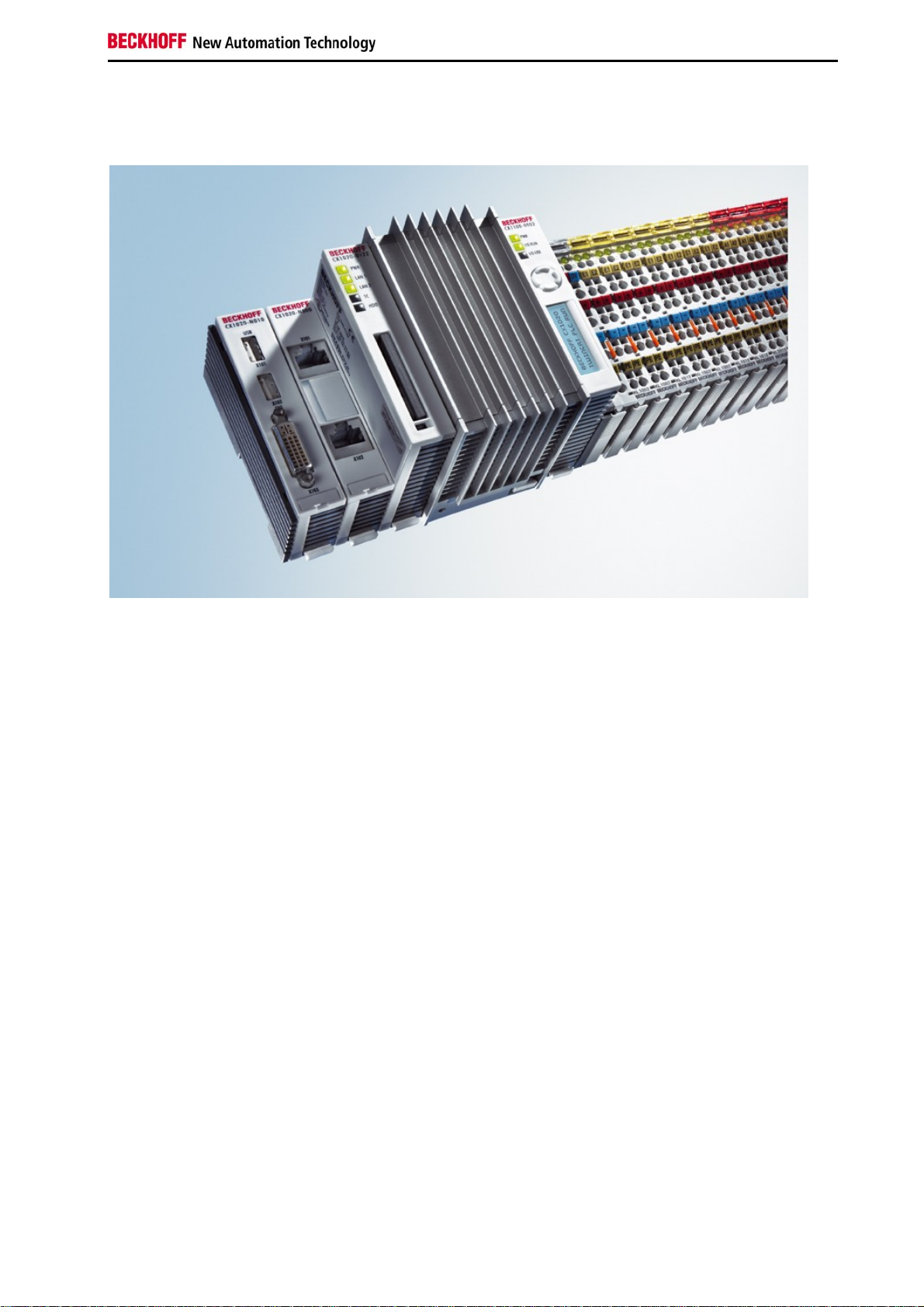
System overview
The system
With the CX series of Embedded PCs Beckhoff has combined PC technology and modular I/O level to form a top-hat
rail unit in the control cabinet. The CX1020 extends the CX product family by a version with higher CPU performance.
The CX1020 enables direct connection of Bus Terminals and EtherCAT terminals.
While the CX1000 features an 266 MHz AMD Geode processor, the CX1020 is equipped with a 1 GHz Intel(r) CPU.
It is an energy-saving device that operates with ultra-low core voltage and features low thermal power dissipation of
only 7 W TDP (thermal design power). As a result, no fan is required despite the compact design of the CX1020
Embedded PC. Since Compact Flash is used as boot and memory medium, no rotating media are required in the
controller. This is an important aspect for increasing the MTBF (Mean Time Between Failures) of the overall system.
The case and assembly concept of the CX1020 is similar to that of its smaller brother, the CX1000:
It also consists of several components that can be assembled by the user. The simplest configuration consists of a
CPU module and a multi-functional power supply unit. The PC104 bus is used for the connection between these and
all other CX components, although in the CX1020 this was extended with EtherCAT signals. The basic CPU module
is equipped with two RJ-45 sockets and an integrated 3-port switch as standard. In practice, this often means that no
separate switch is required, since a line topology can be configured conveniently:
For example in building installations, where several room controls can be distributed across each floor, which
otherwise would have to be networked via a star topology.
Like the CX1000, the CX1020 can be expanded with optional system interfaces. A DVI-I (=DVI-D + VGA) output, two
USB-2.0 interfaces, up to four RS232 interfaces and audio are available. The four RS232 interfaces feature optodecoupling and can optionally be implemented as RS422/RS.
The same reusability also applies to the multi-functional power supplied units (CX1100-000x) of the CX1020: one
without I/O terminal connection, one with K-Bus connection, one with K-Bus and IP-Link connection for IP-67protected Fieldbus Box modules, and a power supply unit with direct connection facility for Beckhoff EtherCAT
Terminals.
EtherCAT as a fast I/O system
The CX1020 Embedded PC was developed for optimum interaction with EtherCAT. The two Ethernet interfaces of
the CPU module are not primarily intended for EtherCAT operation. The EtherCAT connection is established via the
EK1110 (EtherCAT) extension terminal.
Interestingly, EtherCAT offers several options for connecting conventional fieldbus systems to the CX1020:
either as a CX1500 module directly at the CPU or as an EtherCAT device in terminal form. The PROFIBUS master is
available either as a CX1500-M310 or as a EL6731 EtherCAT terminal. Both types offer the same performance
Embedded PC 9
Page 12

Product overview
characteristics - e.g. both support PROFIBUS DP-V2. In practice, this means that the PROFIBUS master can be
positioned exactly where it is required within a machine. It no longer has to be implemented as a plug-in card in the
IPC or a master controller in the control cabinet.
PLC, Motion Control, interpolation and visualisation
As a top-hat rail IPC and in conjunction with the TwinCAT software from Beckhoff, the CX1020 offers the same
functionality as large Industrial PCs. In terms of PLC, up to four virtual IEC 61131 CPUs can be programmed with up
to four tasks each, with a minimum cycle time of 50 µs. All IEC 61131-3 languages can be used.
Moreover, all TwinCAT functionalities are available for Motion Control applications:
In theory, up to 256 axes can be controlled. In addition to simple point-to-point movements, more complex multi-axis
functions such as "electronic gearbox", "cam plates" and "flying saw" can be implemented. In contrast to the CX1000,
due to its higher CPU performance the CX1020 can now also execute interpolating 3D path movements and
DIN66025 programs.
In addition to real-time execution of control tasks, the TwinCAT real-time kernel ensures that enough time remains for
the user interface (HMI), to communicate with the real-time components via software interfaces such as ADS or OPC.
For the CX1020 the same basic principle applies: it is a programming tool for all controllers.
The complete programming of PLC, Motion Control and visualisation is transferable to all PC controls from Beckhoff,
which is reassuring in cases where it becomes apparent during a project that more processing power is required after
all. In this case a system with higher performance can be used.
Basic CPU module
Further system interfaces or fieldbus connections can be added to the basic CPU module. The CPU module requires
a CX1100 type power supply module.
All CX1500 fieldbus modules and all CX1100 power supply units from the CX1000 series can be used in combination
with the CX1020.
The CX1100-0004 power supply unit offers a direct interface between the CX1020 and the EtherCAT Terminals. The
combination of CX1020, EtherCAT and TwinCAT enables cycle and response times of less than 1 millisecond.
The CPU module is available in several variants. These relate to:
- Internal memory configuration: there are three options - either 64 MB Flash/256 MB DDR RAM (standard), 512 MB
RAM, or 1 GB RAM.
- System interface configuration: as an option, a DVI and two USB Interfaces can be added to the combination of two
Ethernet and RJ 45 ports that are always present.
- Operating system: There is a choice between "Microsoft Windows CE.NET" or "Microsoft Windows XP Embedded".
- Pre-installed TwinCAT software: CX1020 can be pre-installed without a TwinCAT system, with TwinCAT CE PLC,
TwinCAT CE NC PTP or TwinCAT CE NCI, or with the associated full version of the individual TwinCAT levels for
PLC and Motion Control.
System interfaces
Further system interfaces for serial communication (2x RS 232 or RS422, RS485), 2 x USB 2.0 interfaces, video
output (DVI +) , CF card reader/writer or audio signals can be ordered separately.
Fieldbus interfaces
All CX1500 fieldbus modules and all CX1100 power supply units from the CX1000 series can be used in combination
with the CX1020.
The fieldbus interfaces are currently available as master and slave versions for the following fieldbuses:
Beckhoff Lightbus, Profibus DP, CANopen, DeviceNet or SERCOS interface (only master)
The master fieldbus connections enable a CX1020 system to use Beckhoff fieldbus components (such as Bus
Coupler, Bus Terminal Controller or Drive Technology) as local control components for complex systems.
Slave fieldbus connections enable the CX1020 system to be used as a subordinate distributed control system for
complex or modular systems.
Note:
Documentation describing the fieldbus connections is available separately.
10 Embedded PC
Page 13

Product overview
The software
In combination with the TwinCAT automation software, the CX1020 Industrial PC becomes a powerful IEC 61131-3
PLC with up to four user tasks. Additionally, Motion Control tasks can also be executed. Depending on the required
cycle time, several servo axes can be controlled. Even special functions such as flying saw, electronic gearbox and
cam plate can be realized.
The CX1020 system is programmed in the same way as other bus controllers:
Remote programming via Ethernet
This option is used if the basic unit is equipped with “Windows CE.NET”. In this case, the system is programmed via
a laptop or a desktop PC, which is connected to the CX1020 via Ethernet (network or crossover cable). The
programs are developed on the laptop with a standard TwinCAT software license and then loaded into the target
device.
Visualization
The Beckhoff OPC server is available for interfacing with SCADA packets, if the two operating system variants
“Windows CE.NET” or “Windows XP Embedded” are used. In other words, the CX1020 also offers straightforward
visualization and simultaneous control in real-time on a single system.
Embedded PC 11
Page 14
Product overview
Basic modules
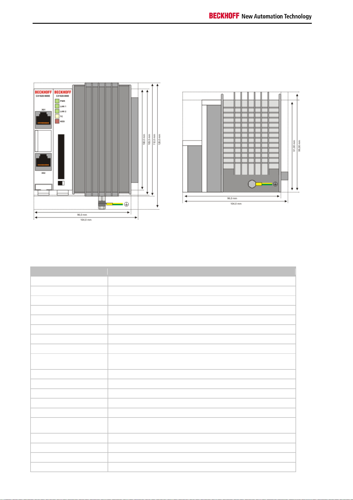
CX1020 Technical Data
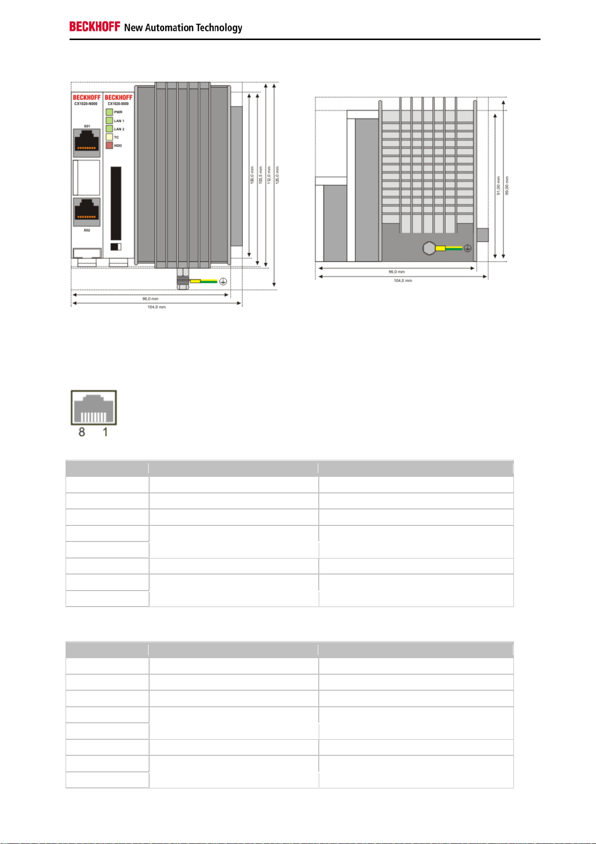
Dimensions:
The basic configuration of the CX1020 includes a 64 MB Compact Flash card. Two Ethernet RJ 45 interfaces are
also part of the basic configuration. These interfaces are connected to an internal switch and offer a simple option for
creating a line topology without the need for additional Ethernet switches. All other CX family components can be
connected via the PC104 interface that is available on both sides.
The passive cooling module is included in the scope of supply. For power supply one of the system power supply
modules (CX1100-000x) is needed)
Technical data CX1020-0000
processor Intel® Celeron® M ULV, 1 GHz clock frequency
Flash memory 64 MB Compact Flash card
Internal main memory 256 MB DDR-RAM (expandable to 512MByte, 1 GB)
Interfaces 2 x RJ45 (internal switch)
Diagnostics LED 1 x Power, 2 x LAN link/activity, 1 x TC, 1 x flash access
Expansion slot 1 x Compact Flash type I+ II insert with eject mechanism
Clock internal battery-backed clock for time and date
Operating system Microsoft Windows CE.NET or Microsoft Windows XP Embedded
Control software TwinCAT PLC Runtime , TwinCAT NC PTP Runtime oder TwinCAT NCI
Runtime
System bus 16 Bit ISA (PC104 standard)
Power supply via system bus (through power supply module CX1100-000x)
Max. power loss 11 W (including CX1100-N0xx systeminterfaces)
Dimensions (W x H x D) 96 mm x 112 mm x 99 mm
Wight app. 550 g
Operating/storage
temperature
Relative humidity 95% no condensation
Vibration/shock resistance conforms to EN 60068-2-6 / EN 60068-2-27/29
EMC resistance burst / ESD conforms to EN 61000-6-2/EN 61000-6-4
protection class IP 20
0° C ... +50° C / -25° C ... +85° C
12 Embedded PC
Page 15
Product overview
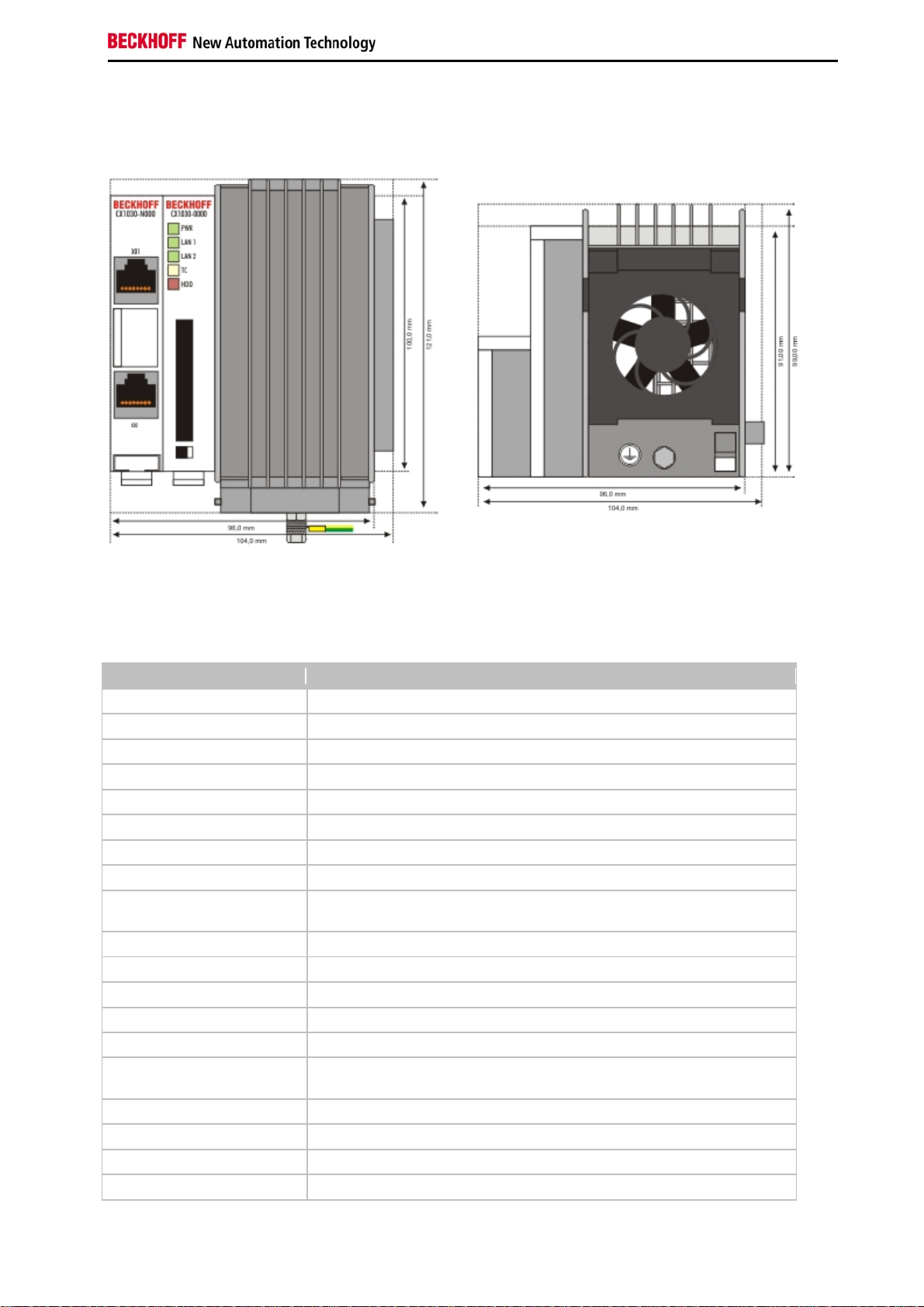
CX1030 Technical Data
Dimensions:
The basic configuration of the CX1030 includes a 64 MB Compact Flash card. Two Ethernet RJ 45 interfaces are
also part of the basic configuration. These interfaces are connected to an internal switch and offer a simple option for
creating a line topology without the need for additional Ethernet switches. All other CX family components can be
connected via the PC104 interface that is available on both sides.
The active cooling module is included in the scope of supply. For power supply one of the system power supply
modules (CX1100-001x) is needed)
Technical data CX1030-0000
processor Intel® Pentium® M, 1.8 GHz clock frequency
Flash memory 64 MB Compact Flash card
Internal main memory 256 MB DDR-RAM (expandable to 512MByte, 1 GB)
Interfaces 2 x RJ45 (internal switch)
Diagnostics LED 1 x Power, 2 x LAN link/activity, 1 x TC, 1 x flash access
Expansion slot 1 x Compact Flash type I+ II insert with eject mechanism
Clock internal battery-backed clock for time and date
Operating system Microsoft Windows CE.NET or Microsoft Windows XP Embedded
Control software TwinCAT PLC Runtime , TwinCAT NC PTP Runtime or TwinCAT NCI
Runtime
System bus 16 Bit ISA (PC104 standard)
Power supply via system bus (through power supply module CX1100-000x)
Max. power loss 11 W (including CX1100-N0xx system interfaces)
Dimensions (W x H x D) 96 mm x 112 mm x 99 mm
Wight app. 550 g
Operating/storage
temperature
Relative humidity 95% no condensation
Vibration/shock resistance conforms to EN 60068-2-6 / EN 60068-2-27/29
EMC resistance burst / ESD conforms to EN 61000-6-2/EN 61000-6-4
protection class IP 20
0° C ... +50° C / -25° C ... +85° C
Embedded PC 13
Page 16

Product overview
Note
For operating this unit need a power supply of type CX1100-001x.
14 Embedded PC
Page 17
Product overview
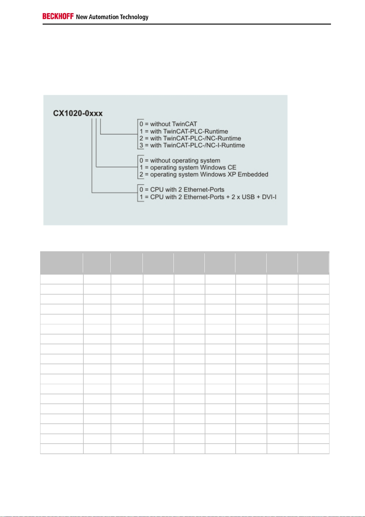
Configurations
The Basic CPU-Module can be ordered with different hardware and software variations. As operating systems there
are "Windows CE.NET" and "Windows XP Embedded" available. The TwinCAT automation software transforms a
CX1020 system into powerful PLC and Motion Control system that can be operated with or without visualisation.
The order identifier of the basic CPU module is derived as follows:
Following CX1020 configurations are available:
no
Ordering
information
CX1020-0000 - X - - X - - -
CX1020-0010 - - X - X - - -
CX1020-0011 - - X - - X - -
CX1020-0012 - - X - - - X -
CX1020-0013 - - X - - - - X
CX1020-0100 X X - - X - - -
CX1020-0110 X - X - X - - -
CX1020-0111 X - X - - X - -
CX1020-0112 X - X - - - X -
CX1020-0113 X - X - - - - X
CX1020-0020 - - - X X - - -
CX1020-0021 - - - X - X - -
CX1020-0022 - - - X - - X -
CX1020-0023 - - - X - - - X
CX1020-0120 X - - X X - - -
CX1020-0121 X - - X - X - -
CX1020-0122 X - - X - - X -
CX1020-0123 X - - X - - - X
CX1020 Systems with Windows XP Embedded require a Compact Flash card with a capacity of al least 1 GB.
DVI /
USB
operating
system
Windows
CE
Windows
XPE
no
TwinCAT
TwinCAT
PLC
Runtime
TwinCAT
NC PTP
Runtime
TwinCAT
NC I
Runtime
Note:
For detailed information about the software images see the CX10x0 Software Documentation.
Embedded PC 15
Page 18
Product overview
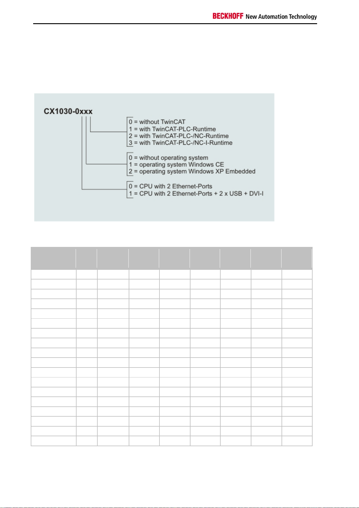
Configurations
The Basic CPU-Module can be ordered with different hardware and software variations. As operating systems there
are "Windows CE.NET" and "Windows XP Embedded" available. The TwinCAT automation software transforms a
CX1030 system into powerful PLC and Motion Control system that can be operated with or without visualisation.
The order identifier of the basic CPU module is derived as follows:
Following CX1030 configurations are available:
no
Ordering
information
CX1030-0000 - X - - X - - -
CX1030-0010 - - X - X - - -
CX1030-0011 - - X - - X - -
CX1030-0012 - - X - - - X -
CX1030-0013 - - X - - - - X
CX1030-0100 X X - - X - - -
CX1030-0110 X - X - X - - -
CX1030-0111 X - X - - X - -
CX1030-0112 X - X - - - X -
CX1030-0113 X - X - - - - X
CX1030-0020 - - - X X - - -
CX1030-0021 - - - X - X - -
CX1030-0022 - - - X - - X -
CX1030-0023 - - - X - - - X
CX1030-0120 X - - X X - - -
CX1030-0121 X - - X - X - -
CX1030-0122 X - - X - - X -
CX1030-0123 X - - X - - - X
CX1030 Systems with Windows XP Embedded require a Compact Flash card with a capacity of al least 1 GB.
DVI /
USB
operating
system
Windows
CE
Windows
XPE
no
TwinCAT
TwinCAT
PLC
Runtime
TwinCAT
NC PTP
Runtime
TwinCAT
NC I
Runtime
Note:
For detailed information about the software images see the CX10x0 Software Documentation.
16 Embedded PC
Page 19
Product overview
Connections
The basic CPU module is available with different hardware and software options. It is supplied from the power supply
unit, so that only the connections are described here.
Basic CPU module with 2 Ethernet RJ 45 interfaces:
RJ 45 interface (socket):
Assignment of the RJ45 interface, Port 1:
PIN Signal Description
1 TD + Transmit +
2 TD - Transmit -
3 RD + Receive +
4 connected not used
5
6 RD - Receive -
7 connected not used
8
TD & RD are exchanged at the hubs or between two PCs.
Assignment of the RJ45 interface, Port 2:
PIN Signal Description
1 TD + Transmit +
2 TD - Transmit -
3 RD + Receive +
4 connected not used
5
6 RD - Receive -
7 connected not used
8
TD & RD are exchanged at the hubs or between two PCs.
Embedded PC 17
Page 20
Product overview
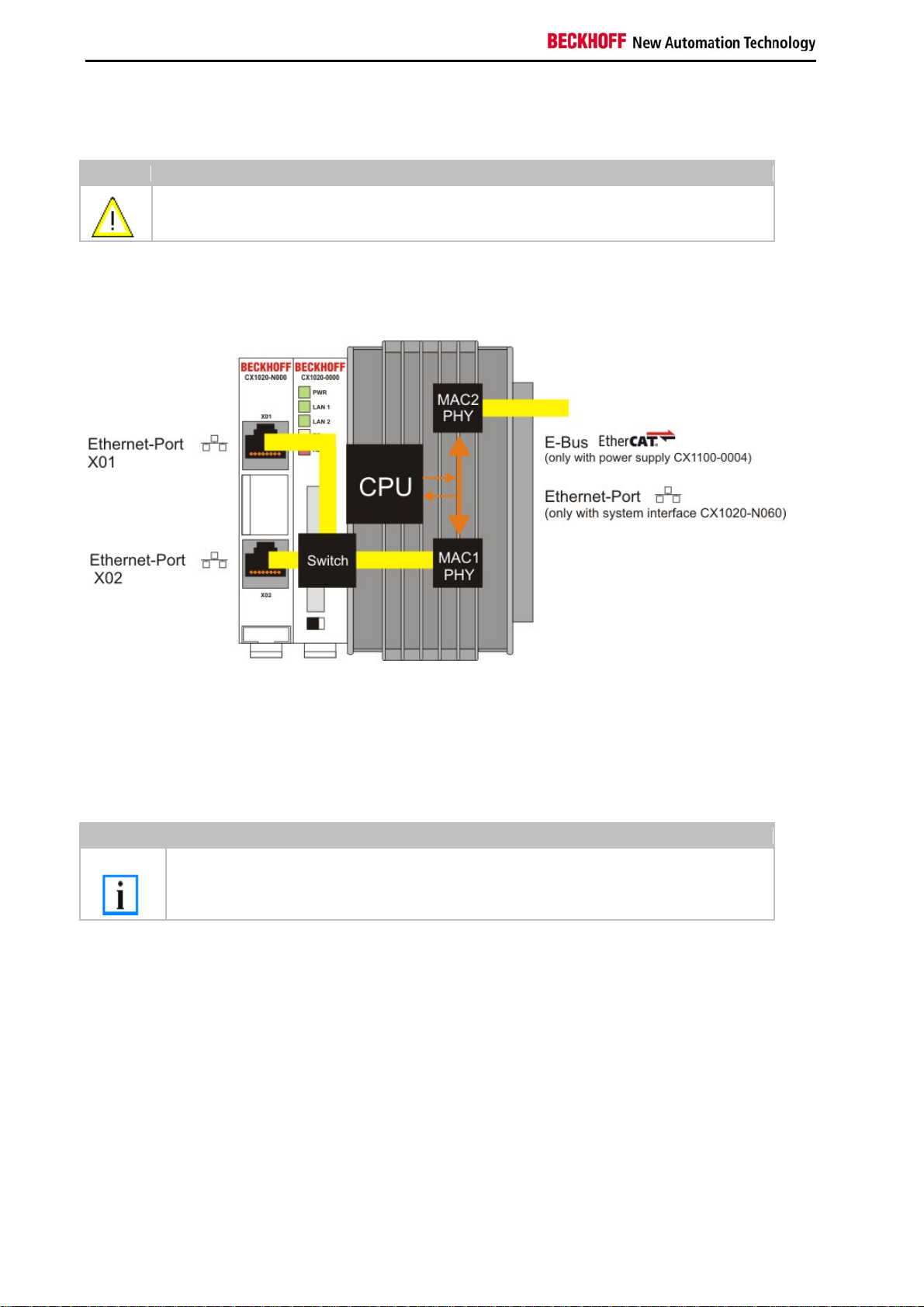
Connection of the Ethernet ports:
Warning
The two Ethernet ports of a basic CPU module must not be connected to the same external
switch!
Schematic structure of the network components:
The CX1020 features two MAC blocks. The first one (MAC1) operates the network interfaces for the Ethernet ports.
The two outputs are connected via a switch. In this way a line structure can be configured as described below. From
an operating system perspective this represents a single connection. The second block (MAC2) operates the
extended PC104 bus. The second physical network connection can be utilised via additional system interfaces. This
requires either a CX1100-0004 power supply unit or a CX1020-N060 system interface. A connection to the E-bus for
EtherCAT terminals is realised via the power supply unit. The CX1020-N060 interface establishes the Ethernet
connection, thereby making a further network interface available.
Note
Only for use in LAN, not for connection to telecommunication circuits.
Operating system perspective:
The operating system only sees one of the connections for the network interface. The status is always connected,
since the switch is connected directly. The internal connection via the PC104 bus extension is shown as the second
interface. If no expansion module is connected, the line is reported as not connected. If the CX1100-00x4 power
supply unit is connected, Windows XPe reports "restricted or no connection". This behavior is normal, since Windows
itself does not use this interface, and therefore no IP address is allocated. If the CX1020-N060 extension is
connected, the connection behaves like a 'normal' network port.
These interfaces are connected to an internal 3-port switch and offer a simple option for creating a line topology
without the need for additional Ethernet switches.
18 Embedded PC
Page 21

Product overview
Basic CPU module with DVI/USB interface:
In addition to the two Ethernet ports, this basic module also features DVI/USB interfaces. The pin assignment of the
basic CPU module with two USB and a DVI-I interface is explained under the associated CX1020-N 010 system
interface.
Applicable to all basic CPU modules:
LED
The green power LED (PWR) is on if the basic CPU module is connected correctly to a live power supply unit.
Compact Flash slot
Further information can be found under Compact Flash slot.
PC 104 Bus
The PC 104 bus is a standardised bus with 104 ISA signals for compact embedded systems.
Embedded PC 19
Page 22
Product overview
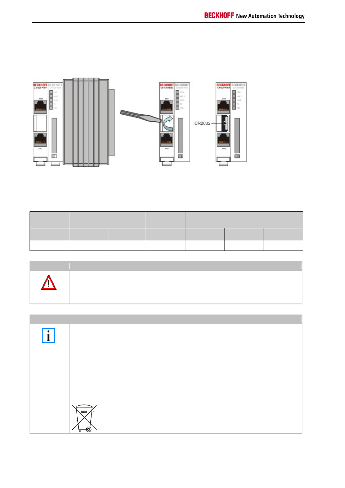
Battery compartment
The battery compartment is located on the left-hand side of the CPU module, between the two Ethernet ports.
It can be opened with the aid of a screwdriver (proceed carefully in order to avoid damage).
The battery is a CR2032 type from Panasonic
with the following specification:
Battery type
CR2032 3.0 V 225 mAh 0.20 mA 20.0 mm 3.20 mm 3.1 g
Danger
Note
Electrical properties
(at 20° C)
nominal
voltage
Replace Battery Part. No. CR2032 manufactured by Sanyo or Panasonic Only. Use of Another
Battery May Present A Risk Of Fire Or Explosion.
WARNING, Battery may explode if mistreated. Do Not Recharge, Disassemble or Dispose of in
fire.
The battery must be changed every 5 years.
Spare batteries can be ordered from Beckhoff Service.
Battery-recycling:
Used batteries must must be disposed of in accordance with national electronics scrap
regulations.
Used batteries may contain harmful substances or heavy metal that can harm the environment
and health. Batteries will be recycled. They contain important commodities as iron, zinc, nickel or
manganese.
The environment and Beckhoff thank for your understanding
nominal
capacity
Standard
charge
continuous
load
Dimensions
Diameter Height Weight
20 Embedded PC
Page 23
Product overview
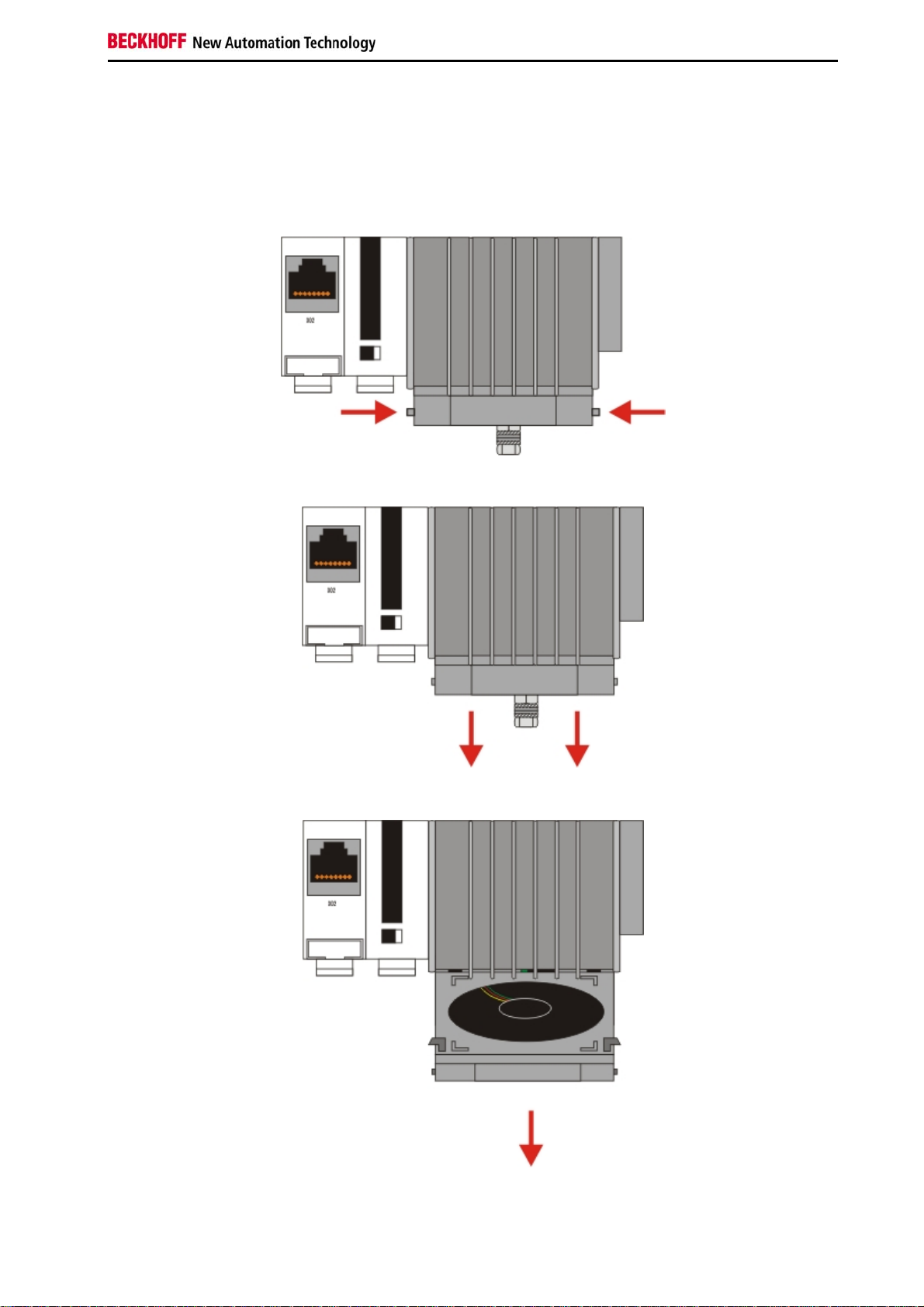
Compact Flash slot
A Compact Flash slot is provided at the front of module. This enables an additional Compact Flash memory medium
(format I or II) to be operated. The change - in case of the Basic CPU module CF slot - is only allowed while the
system is powered down - otherwise the system could crash. In case of using the CF-slot extension (CXxxxx-A001)
the CF card can be removed after signing out the media from the system. The card can be removed for maintenance
or to extend the system storage capacity. The Compact Flash cards (CF cards) are available as accessories with
different storage capacities.
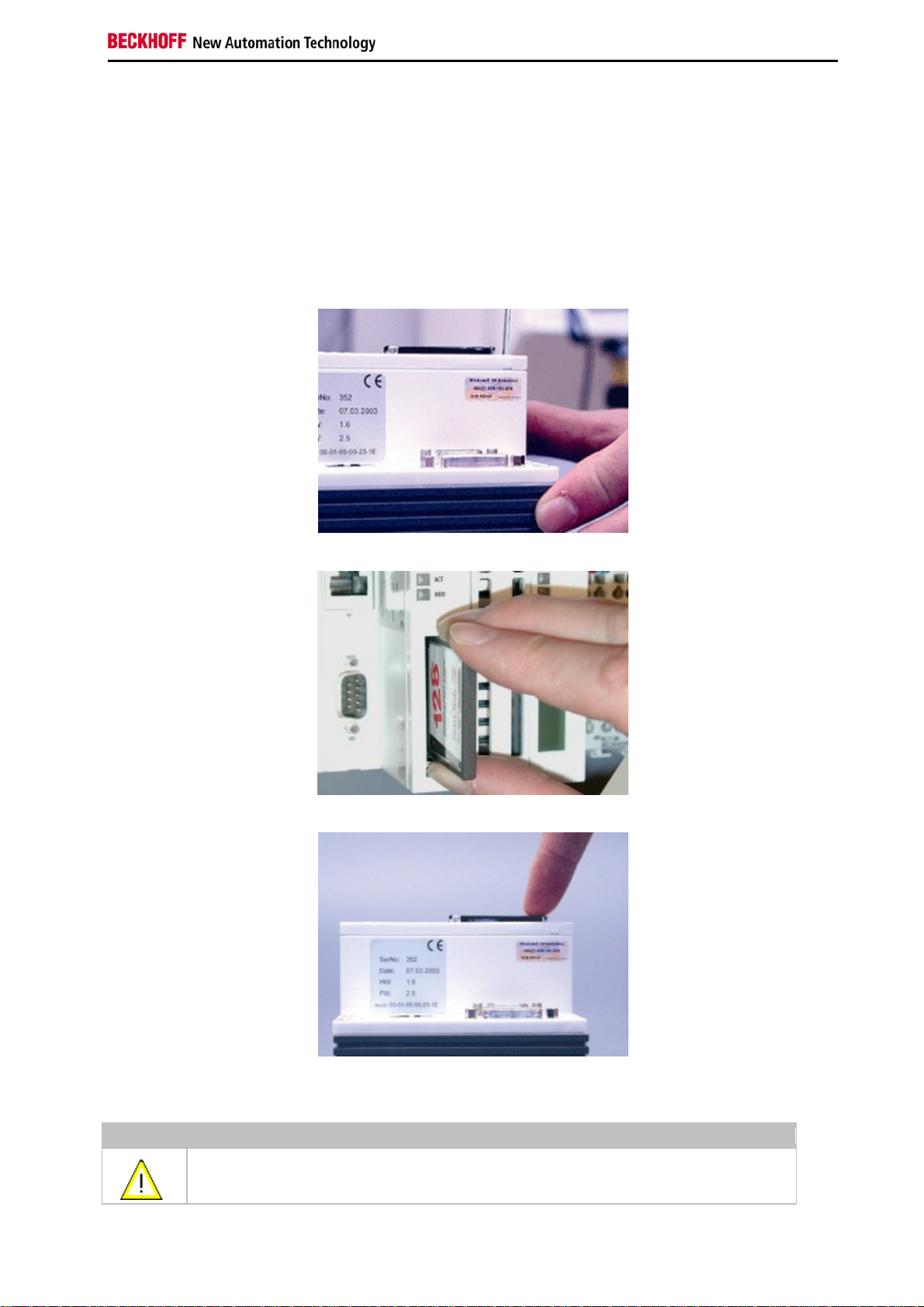
As example the following pictures show the handling of the CF cards with a CX1000 system. Activating the eject
mechanism below the slot with a screwdriver causes the card to be ejected by approx. 4 mm (FIGURE 1), so that it
can be pulled out (FIGURE 2). If the card is pushed in (FIGURE 3), the eject mechanism will re-engage. The card is
positioned correctly, if it is located approx. 1 mm lower than the front of the housing.
FIG1: Ejecting the CF card
FIG2: Removing the CF card
FIG3: Inserting the CF card
Warning
The Compact Flash slot is a memory interface, not an I/O type CF slot.
Embedded PC 21
Page 24

Product overview
Compact-Flash card
The Compact Flash card (CF card) is a non-volatile memory medium.
Data to be retained in the event of a power failure should be saved on the CF card. The CF card operates similar to a
hard disk.
Warning
It is recommended only use CF cards supplied by Beckhoff Automation GmbH.
The CF cards are made for industrial use. They possess a higher number of read / write cycles and
an enhance temperature range (up to + 85°C).
A proper operation of the CX-System can only be guaranteed with the use of CF cards from
Beckhoff Automation GmbH!
22 Embedded PC
Page 25
Product overview
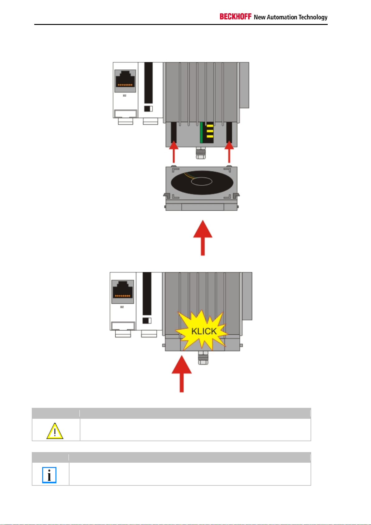
Fan cartridge
On the lower side of the heat sink resides the fan cartridge. The fan is necessary to operate the unit in industrial
environment. Due to the continuous operation the fan needs replacement every 5 years.
0. Shut down the system and switch off power.
1. Press the mounting links on the sides in the direction of the arrows and keep them pressed
2. Move the front of the cartridge down.
3. Take the cartridge towards the front. The cartridge is now removed.
Embedded PC 23
Page 26
Product overview
4. Open the packaging of the new fan cartridge and take out the new cartridge. Hold the cartridge in front of
the mounting notches.Take care that the notches fit the holes in the back of the housing.
5. Move the cartridge up until it snaps in the housing with a click.
Attention The CPU can be damaged
Operation with a defective fan or no fan damage the CPU!
Note
The fan must be changed every 5 years.
Replacement fan cartridges can be orders via Beckhoff Service.
24 Embedded PC
Page 27
Product overview
A
Adapter RAM Hardware address overview
available memory addresses CX1020: D0000-DFFFF (hex)
Base Address
(hex)
D0000 D0FFF 1000 R/W CX1100-0002/3 Dual Ported RAM
D1000 D100F 10 R/W CX1100 Auxiliary Control Block( LCD
D1010 D101F 10 R/W CX1100-0900 UPS Control Block
D2000 D3FFF 2000 R/W CX1100 Non Volatile RAM
D4000 D5FFF 2000 R/W CX1500-M310 Profibus Master
D6000 D7FFF 2000 R/W CX1500-M510 CANopen Master
D8000 D9FFF 2000 R/W CX1500-M520 DeviceNet Master
DA000 DBFFF 2000 R/W CX1500-M200 Lightbus Master
DC000 DDFFF 2000 R/W CX1500-M750 Sercos Master DPRAM
For some fieldbus connections (all Slave modules) the base addresses are mapped in the memory region upper
DFFFF(hex). So these modules must be ordered with other base addresses. The same situation takes place if more
than two or more master modules of same type are used (for more see note below). The order numbers for the
modules are:
order number alternative ISA address
Master connection
CX1500-Mxxx-0001 D4000
CX1500-Mxxx-0002 D6000
CX1500-Mxxx-0003 D8000
CX1500-Mxxx-0004 DA000
CX1500-Mxxx-0005 DC000
Slave connection
CX1500-Bxxx-0001 D4000
CX1500-Bxxx-0002 D6000
CX1500-Bxxx-0003 D8000
CX1500-Bxxx-0004 DA000
CX1500-Bxxx-0005 DC000
Replace xxx with the following number for the requested fieldbus system:
End Address
(hex) Size(Bytes)(hex)
ccess
Type Description
Display, misc. registers)
DPRAM
DPRAM
DPRAM
DPRAM
200 for Lightbus
310 for Profibus
510 for CAN-open
520 for DeviceNet
750 for Sercos (only Master connection available)
Note
Two connection modules (master or slave) can be used simultaneously.
If more than two connections are needed call Beckhoff Automation GmbH for further information.
Embedded PC 25
Page 28

Product overview
PC 104 Bus
The PC 104 bus is a standardized bus with 104ISA signals for compact embedded systems.
For the functionality of the CX1020 modules eight further signals have been added (here marked with color).
Pin assignment of 16 Bit PC 104 Bus:
Pin
Number
1 IOCHCHK* GND GND GND
2 SD7 RESETDRV SBHE* MEMCS16*
3 SD6 +5V LA23 IOCS16*
4 SD5 IRQ9 LA22 IRQ10
5 SD4 n.c. (+12V internal) LA21 IRQ11
6 SD3 DRQ2 LA20 IRQ12
7 SD2 n.c. (+5V internal) LA19 IRQ13
8 SD1 ENDXFR* LA18 IRQ14
9 SD0 +12V LA17 DACK0*
10 IOCHRDY (KEY)² MEMR* DRQ0
11 AEN SMEMW* MEMW* DACK5*
12 SA19 SMEMR* SD8 DRQ5
13 SA18 IOW* SD9 DACK6*
14 SA17 IOR* SD10 DRQ6
15 SA16 DACK3* SD11 DACK7*
16 SA15 DRQ3 SD12 DRQ7
17 SA14 DACK1* SD13 +5V
18 SA13 DRQ1 SD14 MASTER*
19 SA12 REFRESH* SD15 GND
20 SA11 SYSCLK (KEY)² GND
21 SA10 IRQ7 -- --
22 SA9 IRQ6 -- --
23 SA8 IRQ5 -- --
24 SA7 IRQ4 -- --
25 SA6 IRQ3 -- --
26 SA5 DACK2* -- --
27 SA4 TC -- --
28 SA3 BALE -- --
29 SA2 +5V -- --
30 SA1 OSC -- --
31 SA0 GND -- --
32 GND GND -- --
Row A
Row B Row C4 Row D4
26 Embedded PC
Page 29

Product overview
Remarks:
1. B10 and C19 are key locations.
2. Signal timing and function are as specified in ISA specification.
3. Signal source/sink current differs from ISA values.
4. Negative voltages are not supported.
5. in the specification the pins are counted from 0 to 19
Assignment on the 8 additional pins
Pin number (yellow fields) Row C Row D
1 LAN TX- LAN TX+
2 LAN RX- LAN RX+
3 USB D- USB D+
4 SMBDAT SMBCLK
Note:
Further information to PC104 Bus can be found in the datasheet or under http://www.pc104.org.
Embedded PC 27
Page 30
Product overview
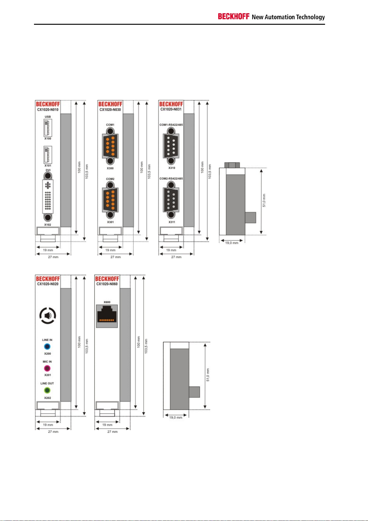
System interfaces
Technical Data
Dimensions:
Like for the CX1000, a number of optional interface modules are available for the basic CX1020 CPU module that
can be installed ex works. The following interfaces are available:
28 Embedded PC
Page 31

Product overview
CX1020-N010 DVI / USB Module
CX1020-N020 Audio interfaces
CX1020-N030/40 serial interface for RS323
CX1020-N031/41 serial interface for RS422 / RS485
CX1020-N060 Ethernet-interface
The CX1020-N010 option can be connected to Beckhoff Control Panels or standard monitors with DVI or VGA input
via the DVI or USB interfaces.Devices such as printer, scanner, mouse, keyboard, mass storage, CR-RW etc. can be
connected via the USB 2.0 interfaces. Multimedia capability is realized via the CX1020-N020 audio interface. The
modules CX1020-N030 and CX1020-N040 offer a total of four serial RS232 interfaces with a maximum transfer
speed of 115 kbaud. These four interfaces can be implemented in pairs as RS422/RS485, in which casethey are
identified as CX1020-N031 and CX1020-N041 respectively.The system interfaces cannot be retrofitted or expanded
in the field. They are supplied ex factory in the specified configuration and cannot be separated from the CPU
module. The system interfaces run through the internal PC104 bus, so that further CX components can
be connected. The power supply of the system interface modules is ensured via the internal PC104 bus.
Embedded PC 29
Page 32

Product overview
CX10x0-N030
Technical data CX10x0-N010 CX10x0-N020
Interfaces 1 x DVI +
2 x USB 2.0
max. 100 mA
Line IN,
MIC IN,
Line OUT
per port
Connection type DVI-I 29-pin
socket + 2 USB
3,5 mm socket
for jack plug
CX10x0-N040
1 x COM1+2,
RS232
1 x COM3+4,
RS232
2 x D-Sub plug
9-pin
Ports type A
Properties DVI-I interface
also carries out
VGA signals
(DVI-A)
built-in PCBeeper
Line OUT output,
max. 200 mW,
suitable for
max. baud rate
115 kbaud,
can not be used
simultaneously with
N031/N041
earphones
Power supply via system bus (Through CX1100-000x power supply module)
Dimensions 19 mm x 100 mm x 51 mm
Operating temperature 0 °C ... +55 °C
Storage temperature -25 °C ... +85 °C
Relative humidity 95% no condensations
Vibration/Shock resistance conforms to EN 60068-2-6 / EN 60068-2-27/29
EMC resistance burst / ESD conforms to EN 61000-6-2/EN 61000-6-4
Protection class IP 20
weight app. 80 g
CX10x0-N031
CX10x0-N041
1 x COM1+2,
RS422/RS485
1 x COM3+4,RS422/RS485
2 x D-Sub plug 9-pin
max. baud rate 115 kbaud,
can not be used
simultaneously with
N030/N040
Technical data CX10x0-N060
Interfaces 1 x Ethernet 10/100 Mbit
Connection type 1 x RJ45
Properties network connection for enhanced
PC104 Bus
Power supply via system bus (Through CX1100-000x power supply module)
Dimensions 19 mm x 100 mm x 51 mm
Operating temperature 0 °C ... +55 °C
Storage temperature -25 °C ... +85 °C
Relative humidity 95% no condensations
Vibration/Shock resistance conforms to EN 60068-2-6 / EN 60068-2-27/29
EMC resistance burst / ESD conforms to EN 61000-6-2/EN 61000-6-4
Protection class IP 20
weight app. 80 g
30 Embedded PC
Page 33

Product overview
CX1020-N001 connections
In addition to the two Ethernet interfaces, this module features a DVI-I and two USB interfaces.
DVI-I interface
The DVI-I interface transfers analog and digital data and is suitable for connection to analog graphics cards with 15
pin D-Sub connector and digital graphics cards with DVI-D output. The resolution at the screen or the Beckhoff
Control Panel depends on the distance (maximum 5 m).
The DVI interface uses VGA signals, so that the connection of CRT VGA monitors to the CX1000 system using a DVI
to VGA adapter is also possible.
This adapter is available as an accessory.
DVI-I socket:
Pin Assignment Pin Assignment PinAssignment
1 TMDS Data 2- 9 TMDS Data 1- 17 TMDS Data 0-
2 TMDS Data 2+ 10 TMDS Data 1+ 18 TMDS Data 0+
3 TMDS Data 2/4 Shield 11 TMDS Data 1/3 Shield 19 TMDS Data 0/5 Shield
4 not connected 12 not connected 20 not connected
5 not connected 13 not connected 21 not connected
6 DDC Clock 14 + 5V Power 22 TMDS Clock Shield
7 DDC Data 15 Ground ( +5V, Analog H/V Sync) 23 TMDS Clock +
8 Analog Vertical Sync 16 Hot Plug Detect 24 TMDA Clock -
Embedded PC 31
Page 34

Product overview
r
Pin assignment (cross)
Pin Assignment
C1 Analog Red Video Out
C2 Analog Green Video Out
C3 Analog Blue Video Out
C4 Analog Horizontal Sync
Resolution at the monitor:
Resolution in pixels Distance of the interface from the monito
1600 x 1200 5 m
1280 x 1024 5 m
1024 x 768 5 m
800 x 600 5 m
640 x 480 5 m
USB interface:
The USB socket is a type A socket. The USB interface complies to USB 2.0 specification
Pin Assignment Typical assignment
1 VBUS Red
2 D- White
3 D+ Green
4 GND Black
Shell Shield Drain Wire
32 Embedded PC
Page 35

Product overview
CX1020-N020 connections
This system interface provides the audio interface for the CX1020 system. Two inputs, "LINE IN" and "MIC IN", are
available. The "LINE OUT" connection is used as output for audio signals. It can also be used for connecting
headphones with a maximum output of 200 mW. It also features a PC beeper. The audio interfaces are accessed via
the operating system. "Windows XPe" offers an option for switching the audio module to surround mode.
The 3.5 mm sockets are designed for jack plugs.
Standard / stereo mode:
The audio module operates in stereo mode as standard, using stereo outputs/inputs and a single-channel input for
the microphone. The inputs should be connected as indicated. The pin assignments are described below.
Line In / Line Out stereo jack plugs:
Pin assignment Line In /Line Out:
Signal Description
L left channel
R right channel
Ground Ground
The left channel is transferred via the tip of the jack plug, the right channel via the first ring. The remainder of the
sleeve is used for earthing.
Mic In mono jack plug:
Embedded PC 33
Page 36

Product overview
The only existing channel is transferred via the tip, the remainder of the sleeve is used for earthing.
Surround sound mode
Two surround sound modes can be set via the Codec driver:
4 speakers (R/L front, R/L back)
5:1 speakers (R/L front, R/L back, centre and subwoofer)
The connectors are usually colour-coded. Should this not be the case, they should be connected as follows:
"LINE IN" -> R/L back,
"MIC IN" -> subwoofer and centre
"LINE OUT" -> R/L front
The pin assignment is as follows:
Pin assignment:
Signal Description
L left channel, back
R right channel, back
Ground Ground
Signal Description
C centre channel
S subwoofer channel
Ground Ground
Signal Description
L left channel, front
R right channel, front
Ground Ground
34 Embedded PC
Page 37

Product overview
Sound driver settings:
The sound driver is called up by double-clicking on the blue icon with yellow circles in the system tray. The window
"AC97 Audio Configuration" appears. It is used for adapting the driver to the current speaker configuration. The
"General" tab shows the driver data. Direct access to the driver via the system tray can be deactivated via the "Show
icon in system tray" checkbox.
The number of speakers is selected in the "Speaker Configuration" tab. The connection details are displayed on
the right-hand side of the window.
Embedded PC 35
Page 38

Product overview
The colours of the connections shown match those on the CX1020-N020 module. Once a configuration has been set
it can be tested via the "Speaker Test" tab.
Clicking on a speaker causes a signal to be sent to the selected speaker. The user can thus check the positioning or
allocation of the individual speakers to the audio channels. Once all speakers have been set correctly, the surround
sound can be tested via "HRTF Demo".
The test parameters can be set via the selection menus:
36 Embedded PC
Page 39

Product overview
Sound:
LOOPY MUSIC (rhythm consisting of high and low sounds)
Buzzing Bee
Path:
Horizontal
Vertical
Insect Motion (random insect flight)
Manual - horizontal (point controlled by mouse movement)
Manual - vertical (point controlled by mouse movement)
Environment:
None (no signal modification)
Bathroom (filter)
Concert Hall (filter)
Arena (filter)
Stone Corridor (filter)
Sewer Pipe (filter)
Under Water (filter)
A test signal can be selected via "Sound". The "Path" statement specifies the motion in space. A filter can be selected
under "Environment". The test can be started or stopped via "Play"/"Stop".
If the speaker configuration is unknown, it can be determined via "Connector Sensing". The user can then enter the
configuration in the "Speaker Configuration" tab.
Further filters can be set permanently in the "Sound Effect" tab. A wide range of environment filters are available.
By default no filter is selected. Further filter functions such as "Auto Gain Control" (signal amplification) or "Voice
Cancellation" are available for voice filtering.
Embedded PC 37
Page 40

Product overview
Parameters for controlling certain frequency bands can be set under "Equalizer". Standard settings for certain types
of music (e.g. rock, pop, bass, ...) are also available.
Noise suppression for the microphone input can be selected in the "Microphone" tab.
Although the "S/PDIF In" and "S/PIF Out" tabs are available in the driver, they are currently not supported.
38 Embedded PC
Page 41

Product overview
CX1020-N030/40 connections
The CX1020-N030 system interface features two RS232 interfaces, COM1 and COM2 (9 pin Sub-D plug connector).
If there is need for more than two serial interfaces two further RS232 interfaces, COM3 and COM4 (9 pin Sub-D plug
connector) can be added to the system via the system interface CX1020-N40. The maximum baud rate on all
channels is 115 kBit. The pin assignment for all interfaces is equal and described below. The interface parameter can
be set in the operating system or in the PLC program.
RS232 COM interface (connector):
Pin assignment COM interface:
PIN Signal Type Description
1 DCD Signal in Data Carrier Detected
2 RxD Signal in Receive Data
3 TxD Signal out Transmit Data
4 DTR Signal out Data Terminal Ready
5 GND Ground Ground
6 DSR Signal in Dataset Ready
7 RTS Signal out Request to Send
8 CTS Signal in Clear to Send
9 RI Signal in Ring Indicator
Note
The system interface CX1020-N30 can only be used instead and not simultaneously with system
interface CX1020-N031.
The system interface CX1020-N40 can only be used instead and not simultaneously with system
interface CX1020-N041.
Embedded PC 39
Page 42

Product overview
CX1020-N031/41 connections
The CX1020-N031 system interface features two RS422 / RS 485 interfaces, COM1 and COM2 (9 pin Sub-D plug
connector). If there is need for more than two serial interfaces two further RS422 / RS485 interfaces, COM3 and
COM4 (9 pin Sub-D plug connector) can be added to the system via the system interface CX1020-N41. The
maximum baud rate on all channels is 115 kBit. The pin assignment for all interfaces is equal and described below.
The interface parameter can be set in the operating system or in the PLC program.
RS232 COM interface (connector):
Pin assignment COM interface:
PIN Signal Type Description
2 TxD+ Data-Out + Transmit 422
3 RxD+ Data-In + Receive 422
5 GND Ground Ground
6 VCC VCC +5V
7 TxD- Data-Out - Transmit 422
8 RxD- Data-In - Receive 422
For RS 485 Pin 2 and 3 ( Data +) as well as Pin7 and 8 (Data -) have to be connected..
Setting the interface parameter
If the system interface CX1020-N031/N041 resides at the end of the CX1020-system block, it is easy to access the
dip switches. The dip switches for the configuration of the RS485/422 interfaces can be found at the left side of the
module. If you remove the grey cover you can see the switch:
40 Embedded PC
Page 43

Product overview
The upper switch sets the parameters for the upper interface, the lower switch sets the parameter for the lower
interface. The system must be powered down, if the settings of the switches are changed! The settings for default
use should be mentioned by ordering the interface module.
Settings DIP switches RS485:
RS485 without Echo, End-Point ( Terminated) DEFAULT setting
DIP Status Function
1 off Echo on
2 on Echo off
3 on Auto send on
4 off Always send on
5 on Auto receive on
6 off Always receive on
7 on Term on
8 on Term on
RS485 with Echo, End-Point ( Terminated)
DIP Status Function
1 on Echo on
2 off Echo off
3 on Auto send on
4 off Always send on
5 off Auto receive on
6 on Always receive on
7 on Term on
8 on Term on
Embedded PC 41
Page 44

Product overview
RS485 without Echo, Drop-Point ( without Termination)
DIP Status Function
1 off Echo on
2 on Echo off
3 on Auto send on
4 off Always send on
5 off Auto receive on
6 on Always receive on
7 off Term on
8 off Term on
RS485 with Echo, Drop-Point ( without Termination)
DIP Status Function
1 on Echo on
2 off Echo off
3 on Auto send on
4 off Always send on
5 off Auto receive on
6 on Always receive on
7 off Term on
8 off Term on
Setting DIP-Switches RS422:
RS422 full duplex end point
DIP Status Function
1 on Echo on
2 off Echo off
3 off Auto send on
4 on Always send on
5 off Auto receive on
6 on Always receive on
7 on Term on
8 on Term on
Note
The system interface CX1020-N31 can only be used instead and not at the same time with
system interface CX1020-N030.
The system interface CX1020-N41 can only be used instead and not at the same time with
system interface CX1020-N040.
42 Embedded PC
Page 45

Product overview
CX1020-N060 connections
The CX1020-N060 system interface provides a further network interface. It can only be used if the CX1100-0004
power supply unit is not connected, since in this case the only internal interface available is used for connecting the
Ethernet port. (Details see Basic module description.)
RJ 45 interface (socket):
Assignment of the RJ45 interface, Port 1:
PIN Signal Description
1 TD + Transmit +
2 TD - Transmit -
3 RD + Receive +
4 connected not used
5
6 RD - Receive -
7 connected not used
8
TD & RD are exchanged at the hubs or between two PCs.
Warning
The CX1020-N060 system interface may only be mounted on the right
module. The setup is shown in the following figures.
Proper mounting position:
The interface is located between the CPU module and the power supply unit.
, directly at the CPU
Embedded PC 43
Page 46

Product overview
Incorrect mounting position:
The interface is located to the left of the CPU module, in series with the other system interfaces.
Warning
The connected network cable must not have a length of more than 15 meters!
Note
The CX1020-N060 system interface can only be used in place of
unit, not at the same time
.
the CX1100-0004 power supply
44 Embedded PC
Page 47

Product overview
Power supply units
CX1100-000x | Power supply units and I/O interfaces
A choice of four power supply modules is available for use with a CX10x0 system. The power supply of all other
system components is ensured via the internal PC104 bus; no separate supply lines are required. However, the
CX1100 components offer further important characteristics that go beyond a pure power supply: an integrated
NOVRAM enables the fail-safe storage of process data, an LCD display with two lines of 16 characters each is used
for displaying system and user messages. A 4 + 1 keypad enables user input without additional keyboard or input
panel. Local I/O signals are connected via the CX1100-0002 power supply variant, to which all Beckhoff Bus
Terminals can be connected, or via CX1100-0003, which in addition to the Bus Terminals enables the connection of
Extension Box IExxxx type Beckhoff Fieldbus Box modules. The option to connect Bus Terminals or a fieldbus Box
creates a control system with a very variable, expandable I/O level with large signal variety. The I/O data are stored
in a DPRAM, which is accessible by the CPU via the system bus. The power supply units of the CX system can be
changed in the field: If, for example, local I/O via Bus Terminals is required, CX1100-0001 can be replaced with
CX1100-0002 in the field. EtherCAT terminals can be connected via the CX1100-0004 power supply unit. The I/O
data are stored directly in the main memory of the CX1100-0004 CPU; a DPRAM is no longer required. The CX1100-
0004 power supply unit for EtherCAT terminals can not
module.
be connected in conjunction with the basic CX1000 CPU
The technical data are provided with the individual power supply unit specifications:
CX1100-0001 (no field bus)
CX1100-0002 (K-Bus)
CX1100-0012 (K-Bus for CX1030 and CX10x0 for alternative installation positions)
CX1100-0003 (K-Bus, IP-Link)
CX1100-0013 (K-Bus, IP-Link for CX1030 and CX10x0 for alternative installation positions)
CX1100-0004 (E-Bus)
CX1100-0014 (E-Bus for CX1030 and CX10x0 for alternative installation positions)
An overview of the power supply architecture and a detailed description of the general system components such as
GCB, ACB, NOVRAM, display and keypad can be found in the documentation for the power supply units.
Embedded PC 45
Page 48

Product overview
Technical data CX1100-0001
Dimensions:
One of power supply modules can be selected for a CX10x0 system. The power supply of all other system
components is ensured via the internal PC104 bus; no separate supply lines are required. However, the CX1100
components offer further important characteristics that go beyond a pure power supply: an integrated NOVRAM
enables the fail-safe storage of process data, an LCD display with two lines of 16 characters each is used for
displaying system and user messages.The power supply CX1100-N001 has no I/O interfaces.
Technical data CX1100-0001
Power supply 24 VDC (-15%/+20%) To meet the UL requirements use a 4 A fuse or a power
supply that has to satisfy NEC class 2!
Dielectric strength 500 V
Max. power consumption 2.5 W
Recommended fuse at 24 V 4 A
connection type 1 x Open Pluggable Connector, 5-pin
NOVRAM 8 kByte
Display FSTN display 2 lines x 16 characters of text, illuminated
I/O-DPRAM -
Diagnose LED 1 x PWR
Dimensions (W x H x D) 45 mm x 100 mm x 91 mm
weight app.180 g
operating/storage
temperature
Relative humidity 95% no condensation
Vibration/shock resistance conforms to EN 60068-2-6 / EN 60068-2-27/29
EMC resistance burst / ESD conforms to EN 61000-6-2 / EN 61000-6-4
protection class IP 20
0° C ... +55° C / -25° C ... +85° C
(supply / internal electronics)
eff
46 Embedded PC
Page 49

Product overview
Technical data CX1100-0002
Dimensions:
Technical data CX1100-0002
Power supply 24 VDC (-15%/+20%) To meet the UL requirements use a 4 A fuse or a power
supply that has to satisfy NEC class 2!
Dielectric strength 500 V
Max. power consumption 3.5 W
Recommended fuse at 24 V 4 A
K-bus connection yes (adapter terminal)
E-bus connection -
IP-Link connection -
K-bus power supply to 1.75 A
connection type Cage-Clamp (adapter terminal)
NOVRAM 8 kByte
Display FSTN display 2 lines x 16 characters of text, illuminated
I/O-DPRAM 2 kByte
Diagnose LED 1 x PWR, 1 x I/O Run, 1 x 1/O Err
Dimensions (W x H x D) 40 mm x 100 mm x 91 mm
weight app.250 g
operating/storage
temperature
Relative humidity 95% no condensation
Vibration/shock resistance conforms to EN 60068-2-6 / EN 60068-2-27/29
EMC resistance burst / ESD conforms to EN 61000-6-2 / EN 61000-6-4
protection class IP 20
(supply / internal electronics)
eff
0° C ... +55° C / -25° C ... +85° C
Embedded PC 47
Page 50

Product overview
Technical data CX1100-0012
Dimensions:
Technical data CX1100-0012
Power supply 24 VDC (-15%/+20%) To meet the UL requirements use a 4 A fuse or a power
supply that has to satisfy NEC class 2!
Dielectric strength 500 V
Max. power consumption 3.5 W
Recommended fuse at 24 V 4 A
K-bus connection yes (adapter terminal)
E-bus connection -
IP-Link connection -
K-bus power supply to 1.75 A
connection type Cage-Clamp (adapter terminal)
NOVRAM 8 kByte
Display FSTN display 2 lines x 16 characters of text, illuminated
I/O-DPRAM 2 kByte
Diagnose LED 1 x PWR, 1 x I/O Run, 1 x 1/O Err
Dimensions (W x H x D) 40 mm x 100 mm x 91 mm
weight app.250 g
operating/storage
temperature
Relative humidity 95% no condensation
Vibration/shock resistance conforms to EN 60068-2-6 / EN 60068-2-27/29
EMC resistance burst / ESD conforms to EN 61000-6-2 / EN 61000-6-4
protection class IP 20
0° C ... +55° C / -25° C ... +85° C
(supply / internal electronics)
eff
48 Embedded PC
Page 51

Product overview
Technical data CX1100-0003
Dimensions:
Technical data CX1100-0003
Power supply 24 VDC (-15%/+20%) To meet the UL requirements use a 4 A fuse or a power
supply that has to satisfy NEC class 2!
Dielectric strength 500 V
Max. power consumption 4 W
Recommended fuse at 24 V 4 A
K-bus connection yes (adapter terminal)
E-bus connection -
IP-Link connection yes
K-bus power supply to 1.75 A
connection type Cage-Clamp (adapter terminal)
NOVRAM 8 kByte
Display FSTN display 2 lines x 16 characters of text, illuminated
I/O-DPRAM 4 kByte
Diagnose LED 1 x PWR, 1 x I/O Run, 1 x 1/O Err
Dimensions (W x H x D) 58 mm x 100 mm x 91 mm
weight app.350 g
operating/storage
temperature
Relative humidity 95% no condensation
Vibration/shock resistance conforms to EN 60068-2-6 / EN 60068-2-27/29
EMC resistance burst / ESD conforms to EN 61000-6-2 / EN 61000-6-4
protection class IP 20
(supply / internal electronics)
eff
0° C ... +55° C / -25° C ... +85° C
Embedded PC 49
Page 52

Product overview
Technical data CX1100-0013
Dimensions:
Technical data CX1100-0013
Power supply 24 VDC (-15%/+20%) To meet the UL requirements use a 4 A fuse or a power
supply that has to satisfy NEC class 2!
Dielectric strength 500 V
Max. power consumption 4 W
Recommended fuse at 24 V 4 A
K-bus connection yes (adapter terminal)
E-bus connection -
IP-Link connection yes
K-bus power supply to 1.75 A
connection type Cage-Clamp (adapter terminal)
NOVRAM 8 kByte
Display FSTN display 2 lines x 16 characters of text, illuminated
I/O-DPRAM 4 kByte
Diagnose LED 1 x PWR, 1 x I/O Run, 1 x 1/O Err
Dimensions (W x H x D) 58 mm x 100 mm x 91 mm
weight app.350 g
operating/storage
temperature
Relative humidity 95% no condensation
Vibration/shock resistance conforms to EN 60068-2-6 / EN 60068-2-27/29
EMC resistance burst / ESD conforms to EN 61000-6-2 / EN 61000-6-4
protection class IP 20
0° C ... +55° C / -25° C ... +85° C
(supply / internal electronics)
eff
50 Embedded PC
Page 53

Product overview
Technical data CX1100-0004
Dimensions:
With the CX1100-0004 power supply EtherCAT Terminals can be connected to the CX10x0-System. With CX11000004 the I/O data are stored directly in the main memory of the CPU; a DPRAM is no longer required. The CX11000004 power supply unit for EtherCAT Terminals can not be connected in conjunction with the basic CX1000 CPU
module.
Technical data CX1100-0004
Power supply 24 VDC (-15%/+20%) To meet the UL requirements use a 4 A fuse or a power
supply that has to satisfy NEC class 2!
Dielectric strength 500 V
Max. power consumption 3.5 W
Recommended fuse at 24 V 4 A
K-bus connection -
E-bus connection yes (adapter terminal)
E-bus power supply to 2 A
connection type Cage-Clamp (adapter terminal)
NOVRAM 8 kByte
Display FSTN display 2 lines x 16 characters of text, illuminated
I/O-DPRAM -
Diagnose LED 1 x PWR, 1 x L/A Run, 1 x RUN
Dimensions (W x H x D) 40 mm x 100 mm x 91 mm
weight app.250 g
operating/storage
temperature
Relative humidity 95% no condensation
Vibration/shock resistance conforms to EN 60068-2-6 / EN 60068-2-27/29
EMC resistance burst / ESD conforms to EN 61000-6-2 / EN 61000-6-4
protection class IP 20
0° C ... +55° C / -25° C ... +85° C
(supply / internal electronics)
eff
Embedded PC 51
Page 54

Product overview
Technical data CX1100-0014
Dimensions:
The CX1100-0014 power supply is designed for CX1030.
With the CX1100-0014 power supply EtherCAT Terminals can be connected to the CX10x0-System. With CX11000004 the I/O data are stored directly in the main memory of the CPU; a DPRAM is no longer required. The CX1100-
0014 power supply unit for EtherCAT Terminals can not be connected in conjunction with the basic CX1000 CPU
module.
Technical data CX1100-0014
Power supply 24 VDC (-15%/+20%) To meet the UL requirements use a 4 A fuse or a power
supply that has to satisfy NEC class 2!
Dielectric strength 500 V
Max. power consumption 3.5 W
Recommended fuse at 24 V 4 A
E-bus connection yes (adapter terminal)
E-bus power supply to 2 A
connection type Cage-Clamp (adapter terminal)
NOVRAM 8 kByte
Display FSTN display 2 lines x 16 characters of text, illuminated
I/O-DPRAM -
Diagnose LED 1 x PWR, 1 x L/A Run, 1 x RUN
Dimensions (W x H x D) 40 mm x 100 mm x 91 mm
weight app.250 g
operating/storage
temperature
Relative humidity 95% no condensation
Vibration/shock resistance conforms to EN 60068-2-6 / EN 60068-2-27/29
EMC resistance burst / ESD conforms to EN 61000-6-2 / EN 61000-6-4
protection class IP 20
0° C ... +55° C / -25° C ... +85° C
(supply / internal electronics)
eff
52 Embedded PC
Page 55

Product overview
CX1100-0001 connections
This power supply unit does not have an I/O interface. The power supply is therefore connected through the 5-pin
open pluggable connector. The power supply unit supplies all further system components with a voltage of 24 V DC (15 %/+20%) via the PC104 bus. The dielectric strength of the power supply unit is 500 V
The integrated NOVRAM permits storage of process data that is safe against power failure.
rms
.
Pin Allocation Open Style Connector:
Pin Assignmnet
1
2
3
4
5
+24 V DC
0 V DC
GROUND
reserved / don't use
reserved / don't use
LED:
With proper connection of the power supply unit and with power supply turned on, the power LED (PWR) lights up
green. In the case of a short-circuit, it lights up red.
Embedded PC 53
Page 56

Product overview
CX1100-00x2 connections
This power supply unit is equipped with an I/O interface, which permits connection of the Beckhoff Bus Terminals.
The power is supplied via the upper spring-loaded terminals labelled “24V” and “0V”.
The supply voltage feeds the CX system and supplies a voltage of 24 V DC (-15 %/+20%) to the Bus Terminals via
the K-Bus. The dielectric strength of the power supply unit is 500 V
on, a further power supply is necessary for the Bus Terminals. This is provided by means of the power contacts,
which are not connected to the power supply.
The integrated NOVRAM permits storage of process data that is safe against power failure.
. Since the K-Bus does no more than pass data
rms
CX1100-0002 for CX1000, CX1010 und CX1020 CX1100-0012 for CX1030
LED:
With proper connection of the power supply unit and with power supply turned on, the power LED (PWR) lights up
green. In the case of a short-circuit, it lights up red.
The I/O LEDs display the operation status of the Bus Terminals. Error-free start-up of the configuration is signalled by
the red "I/O ERR" LED being extinguished. If the ”I/O ERR" LED blinks, an error in the area of the terminals is
indicated. The error code can be determined from the frequency and number of blinks.
PE power contacts
The ”PE" power contact must not be used for other potentials.
54 Embedded PC
Page 57

Product overview
CX1100-00x3 connections
This power supply unit permits not only the connection of the Beckhoff Bus Terminals, but also the serial connection
of the Beckhoff fieldbus box modules of the type extension box IExxxx. The power is supplied via the upper springloaded terminals labeled “24V” and “0V”.
The supply voltage feeds the CX system and, over the K-Bus, the Bus Terminals. Since the K-Bus does no more
than pass data on, a further power supply is necessary for the Bus Terminals. This is provided by means of the
power contacts, which are not connected to the power supply.
CX1100-0003 for CX1000, CX1010 und CX1020 CX1100-0013 for CX1030
Fieldbus connection:
Plug the IP link connector into the respective connections, i.e. one fibre-optic cable each into IN (x03) and OUT (x04).
You then connect the other end with the corresponding IP link interface of the extension box. The connection must be
made so that the output of the fieldbus connection is connected to the input of the extension box and vice versa.
LED:
With proper connection of the power supply unit and with power supply turned on, the power LED (PWR) lights up
green. In the case of a short-circuit, it lights up red. The I/O LEDs display the operation status of the Bus Terminals.
Error-free start-up of the configuration is signaled by the red "I/O ERR" LED being extinguished. If the ”I/O ERR" LED
blinks, an error in the area of the terminals is indicated. The error code can be determined from the frequency and
number of blinks.
PE power contacts
The ”PE" power contact must not be used for other potentials.
Embedded PC 55
Page 58

Product overview
CX1100-00x4 connections
This power supply unit is equipped with an I/O interface, which permits connection of the Beckhoff Bus Terminals.
The power is supplied via the upper spring-loaded terminals labeled “24V” and “0V”.
The supply voltage feeds the CX system and supplies a voltage of 24 V DC (-15 %/+20%) to the Bus Terminals via
the E-Bus. The dielectric strength of the power supply unit is 500 V
on, a further power supply is necessary for the Bus Terminals. This is provided by means of the power contacts,
which are not connected to the power supply.
The integrated NOVRAM permits storage of process data that is safe against power failure.
. Since the E-Bus does no more than pass data
rms
CX1100-0004 for CX1000, CX1010 und CX1020 CX1100-0014for CX1030
LED:
With proper connection of the power supply unit and with power supply turned on, the power LED (PWR) lights up
green. In the case of a short-circuit, it lights up red.
PE power contacts
The ”PE" power contact must not be used for other potentials.
Note
Note
This power supply is designed for use with CX1020 systems only. Operation with CX1000 systems
is not possible because the EtherCAT protocol is not implemented / designed in the hardware of
the CX1000 systems.
The power supply CX1100-0004 can only be used instead and not simultaneously with system
interface CX1020-N060
Warning
It is important to keep attention to the hardware revision of the power supply. Power supplies with
a hardware revision > 2.0 only work with CX1020 systems with a hardware revision > 2.1 !
56 Embedded PC
Page 59

Product overview
LC Display
The LC Display of the power supply units has two rows of 16 characters each and is used for displaying system and
user messages.
"Index-Group/Offset" Specification for the LC Display
ADS Port 300
Index
Group Index Offset Access
0x00005000
+ DeviceID
0x00005000
+ DeviceID
0x00005000
+ DeviceID
0x00005000
+ DeviceID
0x00005000
+ DeviceID
0x00005000
+ DeviceID
0x00005000
+ DeviceID
0x00005000
+ DeviceID
0x00005000
+ DeviceID
0x00005000
+ DeviceID
0xFFFF90FF R&W
0xFFFF91FF R&W
0xFFFF92FF R&W
0xFFFF93FF R&W
0xFFFF94FF R&W
0xFFFF95FF R&W
0xFFFF96FF R&W
0xFFFF97FF R&W
0xFFFFA0FF R&W
0xFFFF00FF R&W
Data
type
Phys.
unit
Def.
range Description Remarks
Cursor OFF
Cursor ON
Cursor blink
OFF
Cursor blink ON
Display OFF
Display ON
Backlight OFF
Backlight ON
Write Text line 1
Write Text line 2
Embedded PC 57
Page 60

Transport
3. Transport
Unpacking, installation and transport
The specified storage conditions must be adhered to (see "Technical data").
Dimensions and weight of the individual modules:
Dimensions (W x H x D): 19 x 100 x 91 mm (system interface) , 96 x 112 x 99 mm (basic module) and 58 x 100 x 91
mm (power supply unit with I/O interface)
Weight: 80 g (system interface) to 550 g (basic module)
Unpacking
Proceed as follows to unpack the unit:
1. Remove packaging.
2. Do not discard the original packaging. Keep it for future relocation.
3. Check the delivery for completeness by comparing it with your order.
4. Please keep the associated paperwork. It contains important information for handling the unit.
5. Check the contents for visible shipping damage.
6. If you notice any shipping damage or inconsistencies between the contents and your order, you should notify
Beckhoff Service.
Warning
Danger of damage to the unit!
Avoid condensation on and inside the unit, If the unit is transported in cold conditions or if the unit is
subjected to extreme fluctuation of temperature.
Prior to operation, the unit must be allowed to slowly adjust to room temperature. Should condensation
occur, a delay time of approximately 12 hours must be waited before the unit is set operational.
Installation
The devices are designed for installation in control cabinets. You will find installation instructions in the chapter
mechanical mounting.
Shipping and relocation
Despite the robust design of the unit, the components are sensitive to strong vibrations and impacts. During
transport, your computer should therefore be protected from excessive mechanical stress. Therefore, please use the
original packaging.
58 Embedded PC
Page 61

Assembly and connecting
4. Assembly and connecting
Mechanical assembly
Dimensions
The CX1000 product range is characterized by small overall installed size and high modularity. For project planning
purposes, a CPU module, a power supply unit and the associated system interfaces and fieldbus interfaces have to
be provided. The overall width of the application is made up of the individual modules. With a height of 100 mm, the
module dimensions exactly match those of the Beckhoff Bus Terminals. Together with the lowered connector
surfaces, this means that it can be used in a standard terminal box with a height of 120 mm.
Warning
To ensure cooling to the device in operation it is important keep the safety distances. Details see
installation position below.
CX1020 Basic CPU-module:
CX1020 Basic CPU-module:
Embedded PC 59
Page 62

Assembly and connecting
CX1000-N00x / CX1020-N0x0 System interfaces:
60 Embedded PC
Page 63

Assembly and connecting
CX1100-000x power supplies:
CX1100-0001
power supply without I/O-interface
CX1100-0002
power supply with I/O-interface (K-Bus-connection)
Embedded PC 61
Page 64

Assembly and connecting
CX1100-0003
power supply with I/O-interfaces (K-Bus-connection and IP-Link)
CX1100-0004 (only use with CX1020 )
power supply with I/O-interface (E-Bus-connection)
62 Embedded PC
Page 65

Assembly and connecting
CX1100-09x0 UPS modules:
CX1100-0900
CX1100-0910
Embedded PC 63
Page 66

Assembly and connecting
CX1100-0920
64 Embedded PC
Page 67

Assembly and connecting
CX1500-Mxxx und CX1500-Bxxx fieldbus connections
All modules for the fieldbus connections (master and slave) have the dimensions (W x H x D) 38 mm x 100 mm x 91
mm.
CX1500-Bxxx
Embedded PC 65
Page 68

Assembly and connecting
CX1500-Mxxx
66 Embedded PC
Page 69

Assembly and connecting
Mechanical assembly of the basic module
The installation of the modules takes place in three steps:
1. The sequence of the modules
The basic CPU module with system interfaces, which are factory-installed on the left side, is extended with the power
supply unit on the right and with the fieldbus connection (master or slave) left side if available.
2. Assembly of the CPU and the power supply unit
The individual modules are simply plugged together. The PC104 connector plugs should be handled carefully in order
to avoid damage. When correctly assembled, no significant gap can be seen between the attached housings.
3. Engaging on the top-hat rail
On the bottom of the modules, there is a white tension strap, which is connected with a latching mechanism. These
tension straps must be pulled down before attaching to the top-hat rail. This can be done using an ordinary
screwdriver and a slight turn.
Embedded PC 67
Page 70

Assembly and connecting
Then fix the CX1020 block on the top hat-rail using the latching straps. You should hear a soft click.
Do not force the module or apply
excessive pressure!
Only apply pressure at insensitive points of the housing (edges). Never apply pressure on the display, the buttons or
movable parts of the CX10x0 system.
After successful latching on the top-hat rail the straps should be pushed back to their original position.
Note:
A locking mechanism prevents the individual housings from being pulled off again. Detailed information relating to
disassembly of the CX1020 configuration from the top-hat rail can be found on page "Removal and disposal".
Installation position:
Warning
The maximum ambient temperature for CPU modules mounted on a top-hat rail is 55°C. The
orientation in which the device is fitted must be selected in such a way that cooling air can flow
vertically through the ventilation holes. The images show the correct (Fig. 8) and two incorrect
installation positions (Figs. 9 & 10).
Observe minimum clearance!
Mounting must provide a clearance of 30 mm both above and below a CX1000 device
combination to ensure adequate ventilation of the base CPU module and the power supply unit.
68 Embedded PC
Page 71

Assembly and connecting
Correct installation position:
The high-performance CX1020 system generates a significant amount of heat, which is dissipated via a passive
ventilation system. This system requires the unit to be mounted correctly. Ventilation openings are located at the top
and bottom of the housing. The system therefore has to be installed horizontally. This ensures optimum air flow.
Incorrect installation positions:
The CX1020 system must not be operated vertically on the top-hat rail. A vertical position would lead to insufficient
CPU ventilation, since the ventilation openings are located on the top and bottom of the housing. Installation of the
system on its side would also lead to inadequate ventilation.
Embedded PC 69
Page 72

Assembly and connecting
Installation positions with active cooling (fan):
Warning
The maximum ambient temperature for CPU modules mounted on a top-hat rail is 55°C. The
orientation in which the device is fitted must be selected in such a way that cooling air can flow
vertically through the ventilation holes. The images show the correct and two incorrect installation
positions.
Observe minimum clearance!
Mounting must provide a clearance of 30 mm both above and below a CX1020/CX1030 device
combination to ensure adequate ventilation of the base CPU module and the power supply unit.
Correct installation position:
The high-performance CX1020/CX1030 system generates a significant amount of heat, which is dissipated via a
passive ventilation system. This system requires the unit to be mounted correctly. Ventilation openings are located at
the top and bottom of the housing. The system therefore has to be installed horizontally. This ensures optimum air
flow.
Incorrect installation positions:
The CX1020/CX1030 system must not be operated vertically on the top-hat rail. A vertical position would lead to
insufficient CPU ventilation, since the ventilation openings are located on the top and bottom of the housing.
Installation of the system on its side would also lead to inadequate ventilation.
70 Embedded PC
Page 73

Assembly and connecting
The installation position "backside down" is only allowed with the right power supply. The power supply should have a
cooling plate (CX1100-001x).
Embedded PC 71
Page 74

Assembly and connecting
Mechanical installation of the fieldbus connection
Installation of a fieldbus connection involves several steps:
1. Removing the cover of the basic CX1020 module
In order to be able to connect the fieldbus to the basic CX1020 module, the cover of the basic CX1000/CX1020
module has to be removed first. This is achieved by applying slight pressure on the cover.
2. Assembly and connection to the CX1000/CX1020 configuration
Since the CX1000 configuration is already positioned on the top-hat rail, the assembly first has to be pushed onto the
top-hat rail. To this end the latching mechanism has to be released by pulling the white straps downwards.
The assembly is connected to the existing CX1000/CX1020 configuration by simply plugging the two units together.
Care must be taken that the plug of the PC104 interface is not damaged.
When correctly assembled, no significant gap can be seen between the attached housings. Finally, the white straps
are returned to their original position, so that the locking mechanism engages.
72 Embedded PC
Page 75

Assembly and connecting
3. Install cover
If the connection area does not have a closing cover on the left-hand side, the cover that was previously removed
should be pressed over the connections until it audibly engages.
Note:
If the CX1000/CX1020 configuration is not positioned on the top-hat rail, it is possible to connect the assembly with
the CX1000/CX1020 configuration first and then latch the whole module onto the top-hat rail. The installation is
described in section Installation and wiring.
Note:
A locking mechanism prevents the individual housings from being pulled off again.
Embedded PC 73
Page 76

Assembly and connecting
Ground connection to cooling element
The cooling element is make of aluminum. Though for proper operating it must be connected to ground. This
connection is realized by a bolt and a screw at the bottom of the cooling element. The set of bolt and screw is
assembled in the factory. To For installation an additional lug and the wire are needed. The ground connection set
does not extend the space the system needs. If the device is installed in correct installing position (30 mm 30 mm
both above and below the housing) no extra space is needed. The dimensions with the ground connection set are as
follows:
The ground connection is realized via a lug of size M4. The following picture shows the order of the grommets and
the lug.
The lug is placed between the middle grommets. First the screw is fixed by turns with the hand. Then a wrench of
size S7 can be used to fix the screw. To avoid damage to the unit, its a good idea to make use of a torque wrench.
Warning
The torque of the screw must not exceed 2,4 Nm! Otherwise the unit might get damaged.
The ground wire must be connected to the ground.
74 Embedded PC
Page 77

Assembly and connecting
Start-up procedure
Switching the PC on and off
Switching on
The power supply for the basic CPU module comes from the power supply unit. The basic CPU module starts
automatically when the power supply unit is connected to the mains.
Switching on for the first time
When you switch on the PC for the first time, the pre-installed operating system (optional) will be started.
Switching off
The Embedded PC switches off when the power supply unit is switched off. The control software typically running on
Embedded PCs should be shut down or stopped correctly. A user who may not close software may also not switch
the Embedded PC off, since data can be lost from the hard disk by switching off while software is running.
Once the software has been stopped, the operating system can be shut down. Only then should the power supply be
interrupted.
Embedded PC 75
Page 78

Assembly and connecting
Note on using the setup
Warning
Within the individual setup pages, F6 can be used for loading fail-safe defaults, and F7 for optimised default values
for the individual setup entries. These default values are applied irrespective of whether the board was previously
booted successfully with a particular setup setting. The situation is different if the defaults are called from the TOP
menu. Once a setup setting that subsequently led to successful booting was saved, both menu items will load these
values as defaults for the setup pages. See also "Load Fail-Safe Defaults" and "Load Optimized Defaults".
Beckhoff Automation GmbH supplies the CX1020 systems pre-configured, which means they are
READY FOR USE!
The BIOS settings should only be modified by appropriately trained staff
Under Windows CE the BIOS should not be changed at all, since the operating system is
adapted to the hardware configuration. Any change in the addresses or interrupts would lead to
unstable system behaviour or even crashing.
.
Top menu
Phoenix - AwardBIOS CMOS Setup Utility
► Standard CMOS Features ► Frequency/Voltage Control
► Advanced BIOS Features
► Advanced Chipset Features
► Integrated Peripherals
► Power Management Setup
► PnP/PCI Configuration
► PC Health Status
ESC: Quit ↑ ↓
→ ← Select Item
F10: Save & Exit Setup
"Brief description of the function selected above"
Load Fail-Save Defaults
Load Optimized Defaults
Set Passwort
Save & Exit Setup
Exit Without Saving
A „►“ sign in front of the menu item indicates that a submenu is available. A „x“ sign in front of a menu item indicates
that a setting option is available that first has to be activated via a higher-level setting.
Load Fail-Save Defaults
This option is used for absolute security settings. It is not suitable for continuous operation, but can be useful if the
PC malfunctions.
Load Optimized Defaults
This option is used for setting optimum values as recommended by the manufacturer.
Set Passwort
Here you can enter a setup password for preventing unauthorised invoking of the BIOS.
76 Embedded PC
Page 79

Assembly and connecting
Save & Exit Setup
This option is used to save the settings and exit setup. Input: Y (Please note: enter Z with German keyboard).
Exit Without Saving
Quit setup without saving the settings. Setting: Y (Please note: enter Z with German keyboard).
Embedded PC 77
Page 80

Assembly and connecting
Standard CMOS Features
This menu is used for setting the date, time, hard disks, graphics mode and start-up behaviour. At the same time,
information about the memory configuration determined by the system is provided. The memory configuration
information cannot be changed. The setting options for date, time, graphics mode and start-up behaviour are
described below. A new menu opens for setting the hard disk data.
Phoenix - AwardBIOS CMOS Setup Utility
Standard CMOS Features
Date (mm:dd:yy) Mon, Jan 30 2006 Item Help
Time (hh:mm:ss) 11 : 11 : 00
► IDE Primary Master [ None]
► IDE Primary Slave [ None]
Video [EGA/VGA]
Halt On [All, But Keyboard]
Base Memory 640K
Extended Memory 228352K
Total Memory 229376K
↑ ↓ → ← :Move Enter:Select +/-/PU/PD:Value F10:Save ESC:Exit F1:Help
F5: Previous Values F6: Fail-Safe Defaults F7: Optimized Defaults
Date (mm:dd:yy)
Options:
mm … month
dd … day
yy … year
Time (hh:mm:ss)
Options:
hh … hours
mm … minutes
ss … seconds
VIDEO
Parameter for setting the graphics mode for the graphics card / the graphics output. EGA / VGA is standard today.
Options:
EGA/VGA
CGA 40
CGA 80
Mono
78 Embedded PC
Page 81

Assembly and connecting
Halt On
This parameter can be used for stopping the boot process in the event of errors. Errors may be ignored. This menu
item is used to configure the settings.
Options:
All Errors (stop for all types of error)
No Errors (ignore all errors and continue system start-up)
All , But Keyboard (missing keyboard is ignored)
Base Memory
This option is used for displaying the conventional memory (0 KB to 640 KB) in order to indicate whether it was
detected by the POST.
Extended Memory
Available memory from the first MB to the maximum memory capacity.
Total Memory
This is the total of base memory, extended memory and other memory.
Embedded PC 79
Page 82

Assembly and connecting
IDE Primary Master
This menu is used for setting the data of the first hard disk connected to the IDE bus as master. The hard disk data
(size, number of cylinders, heads, sectors, pre-compensation and home position of the heads when the disk is
switched off) are displayed automatically for the connected hard disk.
Phoenix - AwardBIOS CMOS Setup Utility
IDE Primary Master
IDE HDD Auto-Detection [Press Enter] Item Help
IDE Primary Master [Auto]
Access Mode [Auto]
Capacity 0 MB
Cylinder
Head 0
Precomp 0
Landing Zone 0
Sector 0
↑ ↓ → ← :Move Enter:Select +/-/PU/PD:Value F10:Save ESC:Exit F1:Help
F5: Previous Values F6: Fail-Safe Defaults F7: Optimized Defaults
IDE HDD Auto-Detection:
Automatic detection of the hard disk is initiated by pressing the <Enter> key. After a few seconds the physical data of
the connected hard disk should be displayed in the lower section of the menu.
IDE Primary Master:
This parameter is used for configuring the IDE bus. The following options are available:
None (no hard disk connected to this bus connection)
Auto (auto-detection during each boot process)
Manual (the hard disk is addressed with the set parameters)
Access Mode:
This option can be used to select the operating system for the hard disk. Setting options: CHS, LBA, LARGE, or Auto.
Auto is the recommended setting. Normal (standard) mode supports hard disks with a capacity of up to 528 MB. This
mode uses positions for data access that are specified via cylinders (CYLS), heads, and sectors. The older LBA
(Logical Block Addressing) mode can support hard disks with a capacity of up to 8.4 GB. This mode uses a different
method for calculating the position disk data to be accessed. It translates cylinders, heads and sectors into a logical
address for the data location. Large hard disks support this mode. The BIOS supports the INT 13h extension function
that enables the LBA mode to manage hard disk drives with a capacity of more than 8.4 GB. If the number of
cylinders (CYLs) on the hard disk exceeds 1024 and DOS cannot support it, or if your operating system does not
support LBA mode, LARGE mode should be selected. The following options are available for setting the hard disk
access mode:
CHS
LBA
LARGE
80 Embedded PC
Page 83

Assembly and connecting
Auto
The following parameters are automatically determined and displayed.
Capacity
Storage capacity of the hard disk. This value is calculated from the individual hard disk parameters.
Cylinder
Define or set the number of cylinders. Depending on the BIOS version and the manufacturer it varies between 1,024
and 16,384 cylinders.
Head
Define or set the number of heads. The number is between 1 and 16 heads.
Precomp
Write pre-compensation, required for older hard disks. This parameter specifies the cylinder from which a difference
in the information density is to be expected.
Landing Zone
This parameter defines the so-called landing zone or park cylinder. This is the resting position for the hard disk head
when the hard disk motor is switched off.
Sector
Define or set the number of sectors per track. Up to 63 sectors are supported, for Phoenix up to 64.
Embedded PC 81
Page 84

Assembly and connecting
IDE Primary Slave
This menu is used for setting the data of the first hard disk connected to the IDE bus as master. The hard disk data
(size, number of cylinders, heads, sectors, pre-compensation and home position of the heads when the disk is
switched off) are displayed automatically for the connected hard disk.
Phoenix - AwardBIOS CMOS Setup Utility
IDE Primary Slave
IDE HDD Auto-Detection [Press Enter] Item Help
IDE Primary Slave [Auto]
Access Mode [Auto]
Capacity 0 MB
Cylinder
Head 0
Precomp 0
Landing Zone 0
Sector 0
↑ ↓ → ← :Move Enter:Select +/-/PU/PD:Value F10:Save ESC:Exit F1:Help
F5: Previous Values F6: Fail-Safe Defaults F7: Optimized Defaults
IDE HDD Auto-Detection:
Automatic detection of the hard disk is initiated by pressing the <Enter> key. After a few seconds the physical data of
the connected hard disk should be displayed in the lower section of the menu.
IDE Primary Slave:
This parameter is used for configuring the IDE bus. The following options are available:
None (no hard disk connected to this bus connection)
Auto (auto-detection during each boot process)
Manual (the hard disk is addressed with the set parameters)
Access Mode:
This option can be used to select the operating system for the hard disk. Setting options: CHS, LBA, LARGE, or Auto.
Auto is the recommended setting. Normal (standard) mode supports hard disks with a capacity of up to 528 MB. This
mode uses positions for data access that are specified via cylinders (CYLS), heads, and sectors. The older LBA
(Logical Block Addressing) mode can support hard disks with a capacity of up to 8.4 GB. This mode uses a different
method for calculating the position disk data to be accessed. It translates cylinders, heads and sectors into a logical
address for the data location. Large hard disks support this mode. The BIOS supports the INT 13h extension function
that enables the LBA mode to manage hard disk drives with a capacity of more than 8.4 GB. If the number of
cylinders (CYLs) on the hard disk exceeds 1024 and DOS cannot support it, or if your operating system does not
support LBA mode, LARGE mode should be selected. The following options are available for setting the hard disk
access mode:
CHS
LBA
LARGE
82 Embedded PC
Page 85

Assembly and connecting
Auto
The following parameters are automatically determined and displayed.
Capacity
Storage capacity of the hard disk. This value is calculated from the individual hard disk parameters.
Cylinder
Define or set the number of cylinders. Depending on the BIOS version and the manufacturer it varies between 1,024
and 16,384 cylinders.
Head
Define or set the number of heads. The number is between 1 and 16 heads.
Precomp
Write pre-compensation, required for older hard disks. This parameter specifies the cylinder from which a difference
in the information density is to be expected.
Landing Zone
This parameter defines the so-called landing zone or park cylinder. This is the resting position for the hard disk head
when the hard disk motor is switched off.
Sector
Define or set the number of sectors per track. Up to 63 sectors are supported, for Phoenix up to 64.
Embedded PC 83
Page 86

Assembly and connecting
Advanced BIOS Features
This menu is used for setting the data of the first hard disk connected to the IDE bus as master. The hard disk data
(size, number of cylinders, heads, sectors, pre-compensation and home position of the heads when the disk is
switched off) are displayed automatically for the connected hard disk.
Phoenix - AwardBIOS CMOS Setup Utility
Advanced BIOS Features
► CPU Feature [Press Enter] Item Help
Virus Warning [Disabled]
CPU L1 & L2 Cache [Enabled]
Quick Power On Self Test [Enabled]
First Boot Device [LS120]
Second Boot Device [HDD-0]
Third Boot Device [LS120]
Boot Other Device [Enabled]
Boot Up NumLock Status [On]
Gate A20 Option [Fast]
Typematic Rate Setting [Disabled]
Typematic Rate (Chars/Sec) 6
Typmatic Delay (Msec) 250
Security Option [Setup]
APIC Mode [Enabled]
MPS Version Control For OS [1.4]
OS Select For DRAM > 64 MB [Non-OS2]
Report No FDD For WIN 95 [No]
Full Screen Logo [Disabled]
↑ ↓ → ← :Move Enter:Select +/-/PU/PD:Value F10:Save ESC:Exit F1:Help
F5: Previous Values F6: Fail-Safe Defaults F7: Optimized Defaults
CPU Feature
This menu item can be used for setting the CPU behaviour for thermal profiles.
Virus Warning
On start-up the boot sectors are checked for changes since the last start. Setting options: Enabled (a virus warning
may appear until it is acknowledged with Confirm or switched off (Disabled)), Confirm (a required boot sector
modification, e.g. after reinstallation of an operating system, is confirmed), Disabled (boot sectors are not verified).
CPU L1 & L2 Cache
The cache memory is an additional memory that is substantially faster than the conventional DRAM (system
memory). If the CPU requests data, the system transfers theses data from the main DRAM to the cache memory for
faster access by the CPU. Setting options: Enable (standard) - cache activated, Disabled - cache deactivated.
Quick Power On Self Test
If this option is enabled the computer will start significantly faster. Booting will be up to 50 seconds faster with 64 MB
RAM or more. However, not all POST tests are carried out.
First Boot Device
Here you can specify which drive should boot first. Set the drive to be used as boot drive. Options:
LS120 (LS-Drive)
84 Embedded PC
Page 87

Assembly and connecting
HDD-0 (Festplatte 1)
SCSI (SCSI-Gerät mit Device Id 0)
CDROM (CD-Laufwerk)
HDD-1 (Festplatte 2)
ZIP100 (Zip-Drive)
USB-FDD (USB-Floppy)
USB-ZIP (USB Zip-Drive)
USB-CDROM (USB CDROM)
USB-HDD (USB-Festplatte)
LAN (Netzwerk)
Disabled (abgeschaltet)
Second Boot Device
This setting is used for booting, if the first boot device is not available. Options:
LS120 (LS-Drive)
HDD-0 (Festplatte 1)
SCSI (SCSI-Gerät mit Device Id 0)
CDROM (CD-Laufwerk)
HDD-1 (Festplatte 2)
ZIP100 (Zip-Drive)
USB-FDD (USB-Floppy)
USB-ZIP (USB Zip-Drive)
USB-CDROM (USB CDROM)
USB-HDD (USB-Festplatte)
LAN (Netzwerk)
Disabled (abgeschaltet)
Third Boot Device
This setting is used for booting, if the first and second boot device are not available. Options:
LS120 (LS-Drive)
HDD-0 (Festplatte 1)
SCSI (SCSI-Gerät mit Device Id 0)
CDROM (CD-Laufwerk)
HDD-1 (Festplatte 2)
ZIP100 (Zip-Drive)
USB-FDD (USB-Floppy)
USB-ZIP (USB Zip-Drive)
USB-CDROM (USB CDROM)
USB-HDD (USB-Festplatte)
LAN (Netzwerk)
Disabled (abgeschaltet)
Embedded PC 85
Page 88

Assembly and connecting
Boot Other Device
This option offers two choices: Enabled or Disabled. The standard setting is Enabled. The Enabled setting enables
the BIOS to try all three types, i.e. "First Boot Device", "Second Boot Device" or "Third Boot Device".
Boot Up NumLock Status
State of the numeric keypad. With On it is activated, with Off not.
Gate A20 Option
Defines how the memory above 1MB is accessed. This should be set to Fast, in order to activate access through the
chipset. With the Normal setting it is accessed via the keyboard controller. This option may speed up older
computers. The first 64 K Block above 1 MB can be accessed in standard mode via address line A20. DOS will
anchor itself there, if DOS=High is inserted in Config.sys.
Typematic Rate Setting
This parameter is used to specify whether the options Keyboard Typematic Speed, Delay Before Keys Repeat,
Typematic Rate or Typematic Delay are available. If Disabled, the values are set to 6 characters per second, with a
keyboard delay of 250 ms. The settings can also be specified via the operating system.
Typematic Rate (Chars/Sec)
Specifies the repetition rate of the keyboard when a key is pressed. The options are 6, 8, 10, 12, 15, 20, 24 or 30
characters/second.
Typmatic Delay (Msec)
This value determines when the key function is activated after a key is pressed. The options are 250, 500, 750 or
1000 milliseconds.
Security Option
This parameter specifies the option for which a password applies. If the SYSTEM option is selected, a password has
to be entered during PC start-up. If the SETUP option is selected, a password is only required for accessing the
BIOS.
APIC Mode
This parameter switches the APIC Controller (Advanced Programmable Interrupt Controller) on or off. According to
the PC2001 regulations, the system may run in APIC mode. APIC mode offers extended IRQ resources (depending
on the board). Settings: Enabled or Disabled
MPS Version Control For OS
This option specifies what MPS version (Multi-Processor Specification) is used by this board. Setting options: 1.1 or
1.4 For older operating systems 1.1 should be used, otherwise leave as 1.4.
OS Select For DRAM > 64 MB
For OS/2 systems with more than 64 MB RAM, option OS/2 should be used.
Report No FDD For WIN 95
This option should be set to Yes, if no floppy drive is installed. This option enables IRQ6, and the Windows logo is
skipped.
Full Screen Logo
This option can be used to specify that the start logo should fill the whole screen during booting, thereby hiding the
start data. Setting options: Enabled, Disabled
86 Embedded PC
Page 89

Assembly and connecting
CPU Features
This menu is used for setting the CPU behaviour with thermal profiles.
Phoenix – AwardBIOS CMOS Setup Utility
CPU Feature
Thermal Management Thermal Monitor 1 Item Help
Delay Prior to Thermal [Disabled]
Execute Disable bit [Enabled]
↑ ↓ → ← :Move Enter:Select +/-/PU/PD:Value F10:Save ESC:Exit F1:Help
F5: Previous Values F6: Fail-Safe Defaults F7: Optimized Defaults
Thermal Management
The processor used has a thermal monitor. The profile is preset and cannot be changed.
Delay Prior to Thermal
The following options are available: 4, 8, 16 or 32 minutes. This option is only applicable for systems with 0.13µ Intel
Pentium 4 processors with 512 KB L2 cache. These processors come with a thermal monitor consisting of a thermal
sensor and a thermal control circuit (TCC). Once the thermal sensor detects that the processor has reached its
maximum safe operating temperature, the TCC is activated and clocking is reduced to 50-70%. This parameter
should be set to 4 minutes, unless the PC needs longer for booting, in which case a suitable higher value should be
used.
Execute Disable bit
This setting option is only available for certain processors with Execute Disable Bit (XD bit) function. If this option is
set to [Enabled] (activated), the processor can classify areas in memory by where application code can execute and
where it cannot, thereby protecting your memory.
Embedded PC 87
Page 90

Assembly and connecting
Advanced BIOS Features
This menu is used for setting the data of the first hard disk connected to the IDE bus as master. The hard disk data
(size, number of cylinders, heads, sectors, pre-compensation and home position of the heads when the disk is
switched off) are displayed automatically for the connected hard disk.
Phoenix - AwardBIOS CMOS Setup Utility
Advanced BIOS Features
► CPU Feature [Press Enter] Item Help
Virus Warning [Disabled]
CPU L1 & L2 Cache [Enabled]
Quick Power On Self Test [Enabled]
First Boot Device [LS120]
Second Boot Device [HDD-0]
Third Boot Device [LS120]
Boot Other Device [Enabled]
Boot Up NumLock Status [On]
Gate A20 Option [Fast]
Typematic Rate Setting [Disabled]
Typematic Rate (Chars/Sec) 6
Typmatic Delay (Msec) 250
Security Option [Setup]
APIC Mode [Enabled]
MPS Version Control For OS [1.4]
OS Select For DRAM > 64 MB [Non-OS2]
Report No FDD For WIN 95 [No]
Full Screen Logo [Disabled]
↑ ↓ → ← :Move Enter:Select +/-/PU/PD:Value F10:Save ESC:Exit F1:Help
F5: Previous Values F6: Fail-Safe Defaults F7: Optimized Defaults
CPU Feature
This menu item can be used for setting the CPU behaviour for thermal profiles.
Virus Warning
On start-up the boot sectors are checked for changes since the last start. Setting options: Enabled (a virus warning
may appear until it is acknowledged with Confirm or switched off (Disabled)), Confirm (a required boot sector
modification, e.g. after reinstallation of an operating system, is confirmed), Disabled (boot sectors are not verified).
CPU L1 & L2 Cache
The cache memory is an additional memory that is substantially faster than the conventional DRAM (system
memory). If the CPU requests data, the system transfers theses data from the main DRAM to the cache memory for
faster access by the CPU. Setting options: Enable (standard) - cache activated, Disabled - cache deactivated.
Quick Power On Self Test
If this option is enabled the computer will start significantly faster. Booting will be up to 50 seconds faster with 64 MB
RAM or more. However, not all POST tests are carried out.
First Boot Device
Here you can specify which drive should boot first. Set the drive to be used as boot drive. Options:
88 Embedded PC
Page 91

Assembly and connecting
Second Boot Device
This setting is used for booting, if the first boot device is not available.
Boot Other Device
This option offers two choices: Enabled or Disabled. The standard setting is Enabled. The Enabled setting enables
the BIOS to try all three types, i.e. "First Boot Device", "Second Boot Device" or "Third Boot Device".
Boot Up NumLock Status
State of the numeric keypad. With On it is activated, with Off not.
Gate A20 Option
Defines how the memory above 1MB is accessed. This should be set to Fast, in order to activate access through the
chipset. With the Normal setting it is accessed via the keyboard controller. This option may speed up older
computers. The first 64 K Block above 1 MB can be accessed in standard mode via address line A20. DOS will
anchor itself there, if DOS=High is inserted in Config.sys.
Typematic Rate Setting
This parameter is used to specify whether the options Keyboard Typematic Speed, Delay Before Keys Repeat,
Typematic Rate or Typematic Delay are available. If Disabled, the values are set to 6 characters per second, with a
keyboard delay of 250 ms. The settings can also be specified via the operating system.
Typematic Rate (Chars/Sec)
Specifies the repetition rate of the keyboard when a key is pressed. The options are 6, 8, 10, 12, 15, 20, 24 or 30
characters/second.
Typmatic Delay (Msec)
This value determines when the key function is activated after a key is pressed. The options are 250, 500, 750 or
1000 milliseconds.
Security Option
This parameter specifies the option for which a password applies. If the SYSTEM option is selected, a password has
to be entered during PC start-up. If the SETUP option is selected, a password is only required for accessing the
BIOS.
APIC Mode
This parameter switches the APIC Controller (Advanced Programmable Interrupt Controller) on or off. According to
the PC2001 regulations, the system may run in APIC mode. APIC mode offers extended IRQ resources (depending
on the board). Settings: Enabled or Disabled
MPS Version Control For OS
This option specifies what MPS version (Multi-Processor Specification) is used by this board. Setting options: 1.1 or
1.4 For older operating systems 1.1 should be used, otherwise leave as 1.4.
OS Select For DRAM > 64 MB
For OS/2 systems with more than 64 MB RAM, option OS/2 should be used.
Report No FDD For WIN 95
This option should be set to Yes, if no floppy drive is installed. This option enables IRQ6, and the Windows logo is
skipped.
Full Screen Logo
This option can be used to specify that the start logo should fill the whole screen during booting, thereby hiding the
start data. Setting options: Enabled, Disabled
Embedded PC 89
Page 92

Assembly and connecting
Integrated Peripherals
This menu is used for setting the system interfaces.
Phoenix – AwardBIOS CMOS Setup Utility
Integrated Peripherals
► OnChip IDE Device [Press Enter] Item Help
► Onboard Device [Press Enter]
► SuperIO Device [Press Enter]
Onboard Serial Port 3 [3E8/IRQ11]
Onboard Serial Port 4 [2E8/IRQ10]
GPIO 4-5-6-7 1-1-1-1
↑ ↓ → ← :Move Enter:Select +/-/PU/PD:Value F10:Save ESC:Exit F1:Help
F5: Previous Values F6: Fail-Safe Defaults F7: Optimized Defaults
OnChip IDE Device
Here you can set the onboard IDE controller settings.
Onboard Device
Here you can set the settings for the USB and audio interfaces.
SuperIO Device
Here you can set the settings for the serial interfaces (port 1 and port 2).
Onboard Serial Port 3
Configuration of the serial interface settings: IRQ11 (used for the third serial port), Disabled (no interrupt is used).
Setting options: Auto, 3F8/IRQ11, 2F8/IRQ11, 3E8/IRQ11 or 2E8/IRQ11 .
Onboard Serial Port 4
Configuration of the serial interface settings: IRQ10 (used for the fourth serial port), Disabled (no interrupt is used).
Setting options: Auto, 3F8/IRQ10, 2F8/IRQ10, 3E8/IRQ10 or 2E8/IRQ10.
90 Embedded PC
Page 93

Assembly and connecting
Onchip IDE Device
This menu is used for setting the IDE interfaces.
Phoenix – AwardBIOS CMOS Setup Utility
Onchip IDE Device
On-Chip Primary PCI IDE [Enabled] Item Help
IDE Primary Master PIO [Auto]
IDE Primary Slave PIO [Auto]
IDE Primary Master UDMA [Auto]
IDE Primary Slave UDMA [Auto]
IDE HDD Block Mode
[Enabled]
↑ ↓ → ← :Move Enter:Select +/-/PU/PD:Value F10:Save ESC:Exit F1:Help
F5: Previous Values F6: Fail-Safe Defaults F7: Optimized Defaults
On-Chip Primary PCI IDE
If this option is enabled, the primary IDE controller of the board can be used. If an ATAPI-CD-ROM drive is used and
integrated with the secondary IDE channel, hard disk access is not slowed down.
IDE Primary Master PIO
PIO refers to the concept of programmed input and output. Instead of the BIOS issuing an instruction sequence for
initiating a data transfer from or to the hard disk, PIO enables the BIOS to notify the controller what task should be
executed. The task is then fully handled by the controller and the CPU. Your system supports five PIO modes, 0
(standard) to 4, with the main difference relating to timing. If "Auto" (automatic) is selected, the BIOS will assess your
drive and automatically specify the optimum PIO mode. Auto: The BIOS automatically sets the system value
depending on the timing of your hard disk drive. Mode 0-4: You can select a mode suitable mode that matches the
timing your hard drive.
IDEPrimary Master UDMA
This option is used to configure the Ultra-DMA/33 mode of your hard disk. Setting options: Auto, Enabled, Disabled.
The option should be set to Enabled.
IDE Primary Slave UDMA
This option is used to configure the Ultra-DMA/33 mode of your hard disk. Setting options: Auto, Enabled, Disabled.
The option should be set to Enabled.
IDE HDD Block Mode
This option is used to activate block mode for IDE hard disks. If your drive supports this mode and this option is
activated, the system will read the number of blocks per request from the configuration sector of the hard disk. The
recommended setting is Enabled, although it should be noted that this is not suitable for older hard disks.
Embedded PC 91
Page 94

Assembly and connecting
Onboard Device
This menu is used for configuring the USB and audio interfaces.
Phoenix - AwardBIOS CMOS Setup Utility
Onboard Device
USB Controller [Enabled] Item Help
USB 2.0 Controller [Enabled]
USB Keyboard Support [Enabled]
USB Mouse Support [Disabled]
AC97 Audio [Auto]
Init Display First [Onboard/AGP]
↑ ↓ → ← :Move Enter:Select +/-/PU/PD:Value F10:Save ESC:Exit F1:Help
F5: Previous Values F6: Fail-Safe Defaults F7: Optimized Defaults
USB Controller
If the option is enabled, the system BIOS specifies the system resources (IRQs and addresses) to be used. If the
option is disabled, the USB controller is switched off.
USB 2.0 Controller
The board contains a USB 2.0 chipset with support for USB 2.0. The option can be switched on or off here.
USB Keyboard Support
The USB keyboard driver (if available) of the BIOS can be activated/deactivated here. This enables the USB
keyboard to be operated during and after system startup, if your operating system does not have a USB driver.
USB Mouse Support
Select Enabled if your system has a USB controller (Universal Serial Bus) and you are using a USB mouse. The
following settings are available: Enabled, Disabled.
AC97 Audio
The onboard AC'97 audio controller can be switched on or off here. Setting options: Auto, Disabled .
Init Display First
This option can be used to specify which graphics card should be initialised first, i.e. either the card in the PCI slot or
the AGP card. The setting options are "First PCI" or "OnboardAGP".
92 Embedded PC
Page 95

Assembly and connecting
SuperIO Device
This menu is used for configuring the USB and audio interfaces.
Phoenix - AwardBIOS CMOS Setup Utility
SuperIO Device
Onboard Serial Port 1 [3F8/IRQ4] Item Help
Onboard Serial Port 2 [2F8/IRQ3]
UART Mode Select [Normal]
RxD, TxD Active Hi, Lo
IR Transmission Delay Enabled
UR2 Duplex Mode Half
Use IR Pins IR-Rx2Tx2
↑ ↓ → ← :Move Enter:Select +/-/PU/PD:Value F10:Save ESC:Exit F1:Help
F5: Previous Values F6: Fail-Safe Defaults F7: Optimized Defaults
Onboard Serial Port1
Configuration of the serial interface settings: IRQ4 (used for the first serial port), Disabled (no interrupt is used).
Setting options: Auto, 3F8/IRQ4, 2F8/IRQ4, 3E8/IRQ4 or 2E8/IRQ4 .
Onboard Serial Port 2
Configuration of the serial interface settings: IRQ3 (used for the second serial port), Disabled (no interrupt is used).
Setting options: Auto, 3F8/IRQ3, 2F8/IRQ3, 3E8/IRQ3 or 2E8/IRQ3.
UART Mode Select
Mode for the serial interface driver. Setting options:
Normal for RS-232 serial interface
ASKIR for amplitude keyed shift interface for IR devices
IrDA for IrDA interface
RxD, TxD Active
Settings cannot be changed in standard mode. This option is used for setting IR transmission/reception to High or
Low.
IR Transmission Delay
If this option is activated, transmission is delayed. Setting options: Enabled, Disabled.
UR2 Duplex Mode
This option is used for configuring infrared devices. Setting options: Full or Half. Please refer to the IR device manual
regarding the duplex mode setting.
Use IR Pins
This option is identical to the TxD, RxD Active option. The required information can be found in the documentation for
your IR device.
Embedded PC 93
Page 96

Assembly and connecting
Power Management Setup
This menu is used for power management settings.
Phoenix - AwardBIOS CMOS Setup Utility
Power Management Setup
ACPI Function [Enabled] Item Help
Power Management
Video Off Method [DPMS]
Video Off In Suspend [Yes]
Suspend Type [Stop Grant]
Modem Use IRQ [3]
Suspend Mode [Disabled]
HDD Power Down [Disabled]
Wake-Up by PCI card [Enabled]
Power On by Ring [Enabled]
** Reload Global Timer Events **
Primary IDE 0 [Disabled]
Primary IDE 1 [Disabled]
Secondary IDE 0
Secondary IDE 1
FDD, COM, LPT Port
PCI PIRQ[A-D]#
↑ ↓ → ← :Move Enter:Select +/-/PU/PD:Value F10:Save ESC:Exit F1:Help
[User Define]
[Disabled]
[Disabled]
[Disabled]
[Disabled]
F5: Previous Values F6: Fail-Safe Defaults F7: Optimized Defaults
ACPI Function
This option can be used for switching the ACPI (Advanced Configuration and Power Interface) functions on or off (if
available). ACPI requires an operating system that recognises ACPI.
Power Management
Settings: Disabled (no energy saving function used), Min Saving (this setting is activated after 40 minutes and offers
the lowest energy saving level), Max Saving (this setting offers the highest energy saving level).
Video Off Method
Here you can specify how the display is switched off. Since the monitor is one of the largest consumers, this
important option should not be skipped. Most recent monitors come with VESA-DPMS capability (Display Power
Management Signaling or Energy Star). Several options are available. Some monitors switch off automatically in the
absence of a signal from the graphics card. In the absence of power management functionality, or if the other options
are not used, the "blank screen" option may be used. DPMS should be set here. Setting options: Blank Screen, V/H
Sync+Blank. DPMS should only be used for monitors without power management function.
Video Off In Suspend
This option offers two choices: Yes or No. This setting determines how the monitor is switched off.
Suspend Type
This option offers two choices: Stop Grant (the CPU is idle in energy-saving mode), and PwrOn Suspend (the CPU
remains active in energy-saving mode).
Modem Use IRQ
This option is used for specifying the interrupt line (IRQ) of a modem (if present). Activity on this line causes the
computer to 'wake up' in order to receive a fax, for example. Setting options: NA (no allocation), 3 (allocated), 4, 5, 7,
94 Embedded PC
Page 97

Assembly and connecting
9, 10, 11
Suspend Mode
In User Define mode a hold time can be set here. The following values are available: Disable (off) 1 Min , 2 Min , 4
Min, 8 Min , 12 Min , 20 Min , 30Min , 40 Min , 1 Hour. The setting in Min Saving mode is 1 minute. With Max Saving
the hold time is set to 1 hour.
HDD Power Down
Here you can specify after which period of inactivity the hard disk is switched off. This option is only available for IDE
hard disks. Settings: Disabled or 1 to 15 minutes. This option should be used with caution, since frequent switching
on and off is more damaging to the hard disk than beneficial in terms of energy saving.
Wake-Up by PCI card
This option can be used to start your PC from another PC via a network by sending a wake-up frame or signal.
Power On by Ring
The system starts when the phone rings, if an external modem is connected to the onboard serial port.
** Reload Global Timer Events **
Primary IDE 0
If this option is enabled, the system activates the energy-saving timer if no activity is detected on the first drive of the
first IDE/EIDE port. Setting options: Enabled, Disabled
Primary IDE 1
If this option is enabled, the system activates the energy-saving timer if no activity is detected on the second drive of
the first IDE/EIDE port. Setting options: Enabled, Disabled.
Secondary IDE 0
If this option is enabled, the system activates the energy-saving timer if no activity is detected on the first drive of the
second IDE/EIDE port. Setting options: Enabled, Disabled
Secondary IDE 1
If this option is enabled, the system activates the energy-saving timer if no activity is detected on the second drive of
the second IDE/EIDE port. Setting options: Enabled, Disabled
FDD, COM, LPT Port
If one of these menu items is set to "Monitor", the AMI-BIOS monitors the IRQ of the respective connection or device
(and therefore the connection or device itself) for activity while in energy-saving mode. If activity is detected, the
system switches from the respective energy-saving mode to normal mode. The AMI-BIOS resets the standby and
suspend idle time to zero if activity is detected on a specified IRQ.
PCI PIRQ[A-D]#
This option can be used to influence the power management timing. If the option is enabled, a countdown
commences that is interrupted as soon as the INTA~INTD signal becomes active. The system is reset to zero.
Embedded PC 95
Page 98

Assembly and connecting
PnP/PCI Configurations
This menu is used for configuring the PCI bus and Plug and Play Management.
Phoenix - AwardBIOS CMOS Setup Utility
PnP/PCI Configurations
Reset Configuration Data [Enabled] Item Help
Resources Controlled By [Manual]
► IRQ Resources [Press Enter]
► Memory Resources [Press Enter]
PCI/VGA Palette Snoop [Disabled]
↑ ↓ → ← :Move Enter:Select +/-/PU/PD:Value F10:Save ESC:Exit F1:Help
F5: Previous Values F6: Fail-Safe Defaults F7: Optimized Defaults
Reset Configuration Data
If activated, the option ensures that the BIOS deletes the information relating to built-in components and their
resources and reconfigures them (all settings are reset). Setting options: Enabled, Disabled.
Resources Controlled By
Specifies whether the PnP settings should be assigned via setup or automatically. Auto should be used, if there are
no problems with IRQ or DMA assignments.
IRQ Resources
If these resources are set manually, each system interrupt should be assigned a type, depending on the type of
device using the interrupt.
Memory Resources
If memory areas are to be protected for use by the operating system, an area can be set here.
PCI/VGA Palette Snoop
Used by multimedia video cards. This function should be switched on (Enabled), depending on the card. It is
switched off by default.
96 Embedded PC
Page 99

Assembly and connecting
IRQ Resources
This menu is used for disabling interrupts for free allocation to PCI slots.
Phoenix - AwardBIOS CMOS Setup Utility
IRQ Resources
IRQ-3 assigned to [PCI Device] Item Help
IRQ-4 assigned to [PCI Device]
IRQ-5 assigned to [PCI Device]
IRQ-7 assigned to [PCI Device]
IRQ-9 assigned to [PCI Device]
IRQ-10 assigned to [PCI Device]
IRQ-11 assigned to [PCI Device]
IRQ-12 assigned to [PCI Device]
IRQ-14 assigned to [PCI Device]
IRQ-15 assigned to [PCI Device]
↑ ↓ → ← :Move Enter:Select +/-/PU/PD:Value F10:Save ESC:Exit F1:Help
F5: Previous Values F6: Fail-Safe Defaults F7: Optimized Defaults
IRQ-n assigned to ( n = {3,4,5,7,9,10,11,12,14,15} )
This parameter is used for disabling (reserving) an interrupt for free allocation. If the setting [PCI Device] is used, the
interrupt is allocated dynamically.
Embedded PC 97
Page 100

Assembly and connecting
Memory Resources
This menu can be used to specify a memory area for peripherals. The area is precisely defined through a base
address and length.
Phoenix - AwardBIOS CMOS Setup Utility
Memory Resources
Reserved Base [D000] Item Help
Reserved Memory Length [64K]
↑ ↓ → ← :Move Enter:Select +/-/PU/PD:Value F10:Save ESC:Exit F1:Help
F5: Previous Values F6: Fail-Safe Defaults F7: Optimized Defaults
Reserved Base
Start address of the reserved area. N/A (not available), D000, D400, D800 or DC00 can be selected as addresses.
Reserved Memory Length
Size of the memory area in KB. 8K, 16K, 32K or 64K can be set.
98 Embedded PC
 Loading...