

Page 1
Documentation for
CP-Link 3
Ethernet based Desktop Transmission Software
Version: 1.7
Date: 2013-10-17
BECKHOFF CP-Link 3
Page 1
Page 2

TABLE OF CONTENTS
CP-Link 3
3
Foreword
Notes on the documentation
4
Safety Instructions
5
Documentation issue status
6
Product overview
Functioning
8
Software variants
10
Technical data
11
Installation
Installation - Host
12
Installation - Client
18
Uninstallation
22
Configuration
Configuration interface
23
Edit the client list
27
Client Configuration
32
Function monitoring
Client Explorer
41
Network
Network Topology
45
Configuration of RT-Ethernet devices
46
Firewall Configuration
49
Miscellaneous
USB Device Filter Lists
50
Windows Display Settings
52
CP-Link 3 Shell Extension
55
Set the HID focus manually
56
CP-Link 3 Service
59
Using USB devices locally on the client
60
Using the CPx8xx USB Bus Coupler
61
Update of TcUsb.sys
72
CP-Link 3 LaunchApp
74
Hints for cabling
75
Appendix
Comments
76
Troubleshooting
77
Support and Service
79
Page 2
Page 3

Notes on the documentation
This description is only intended for the use of trained specialists in control and automation engineering who are familiar
with the applicable national standards.
It is essential that the following notes and explanations are followed when installing and commissioning these
components.
The responsible staff must ensure that the application or use of the products described satisfy all the requirements for
safety, including all the relevant laws, regulations, guidelines and standards.
Disclaimer
The documentation has been prepared with care. The products described are, however, constantly under development.
For that reason the documentation is not in every case checked for consistency with performance data, standards or
other characteristics.
In the event that it contains technical or editorial errors, we retain the right to make alterations at any time and without
warning.
No claims for the modification of products that have already been supplied may be made on the basis of the data,
diagrams and descriptions in this documentation.
Trademarks
Beckhoff® , TwinCAT® , EtherCAT® , Safety over EtherCAT® , TwinSAFE® and XFC® are registered trademarks of and
licensed by Beckhoff Automation GmbH.
Other designations used in this publication may be trademarks whose use by third parties for their own purposes could
violate the rights of the owners.
Patent Pending
The EtherCAT Technology is covered, including but not limited to the following patent applications and patents:
EP1590927, EP1789857, DE102004044764, DE102007017835
with corresponding applications or registrations in various other countries.
The TwinCAT Technology is covered, including but not limited to the following patent applications and patents:
EP0851348, US6167425 with corresponding applications or registrations in various other countries.
Copyright
© Beckhoff Automation GmbH.
The reproduction, distribution and utilization of this document as well as the communication of its contents to others
without express authorization are prohibited.
Offenders will be held liable for the payment of damages. All rights reserved in the event of the grant of a patent, utility
model or design.
BECKHOFF Automation: Foreword
Page 3
Page 4
Safety instructions
Safety rules
Consider the following safety instructions and descriptions!
Product specific safety instructions are to be found on the following pages or in the areas mounting, wiring,
commissioning etc.
Disclaimer
All the components are supplied in particular hardware and software configurations appropriate for the application.
Modifications to hardware or software configurations other than those described in the documentation are not permitted,
and nullify the liability of Beckhoff Automation GmbH.
Personnel qualification
This description is only intended for the use of trained specialists in control, automation and drive engineering who are
familiar with the applicable national standards.
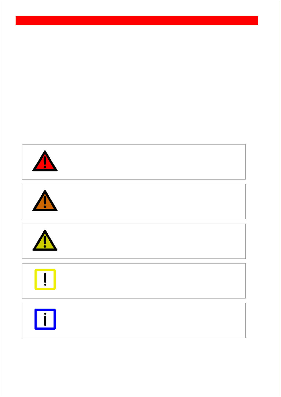
Description of symbols
The following symbols with a adjoining safety advise or notice are used in this documentation. You have to read the
safety advices carefully and adhere them strictly!
DANGER
Acute risk of injury!
If you do not adhere the safety advise adjoining this symbol, there is immediate danger
to life and health of individuals!
WARNING
Risk of injury!
If you do not adhere the safety advise adjoining this symbol, there is danger to life and
health of individuals!
CAUTION
Hazard to individuals!
If you do not adhere the safety advise adjoining this symbol, there is obvious hazard to
individuals!
Attention
Hazard to devices and environment
If you do not adhere the notice adjoining this symbol, there is obvious hazard to
materials and environment.
Note
Note or pointer
This symbol indicates information that contributes to better understanding.
BECKHOFF Automation: Foreword
Page 4
Page 5
Documentation issue status
Version
Comment
1.7
Updated section Client Explorer (USB-Buscoupler )
Updated section Using the CPx8xx USB Bus Coupler (Device number of the USB Bus
Coupler )
Updated section Set the HID focus manually
Updated section Installation - Host
Updated section Installation - Client
1.6
Updated section Technical data
1.5
Updated section Installation - Client (Installation of client software under Windows 7 /
Windows XP )
Updated section Installation - Host
Updated section Edit the client list (Broadcast Search )
Updated section Client Configuration (USB , Serial )
Updated section Client Explorer
Description for Firewall Configuration
Description for USB Device Filter Lists
Updated section Using USB devices locally on the client
New section Hints for cabling
Updated section Toubleshooting
1.4
Updated documentation concerning Windows 7 support
Updated section Configuration interface
Updated section Windows Display Settings
Description for Network Topology
1.3
Description for uninstallation of CP-Link 3 Extended Desktop Devices (Configuration
interface )
Updated section Client Configuration - Resolution of the display device on the host, Transfer
protocol for graphical data
Updated section Using the CPx8xx USB Bus Coupler
Updated section Using USB devices locally on the client
Description for Configuration of RT Ethernet devices
Description for CP-Link 3 LaunchApp
Updated section Set the HID focus manually
Description for CP-Link 3 Service
Description for Client Explorer
BECKHOFF CP-Link 3: Foreword
Page 5
Page 6

Updated section Troubleshooting
1.2
Updated section Technical data - System Requirements for the Client
Description of lock symbol positioning on clients ( Client Configuration )
1.1
Description for installation of CP-Link 3 on clients
Updated description for installation of CP-Link 3 on host PCs
Updated description for usage of USB Bus Couplers with CP-Link 3
1.0
First Release
Page 6
Page 7
Functioning
Ethernet-based desktop transfer software
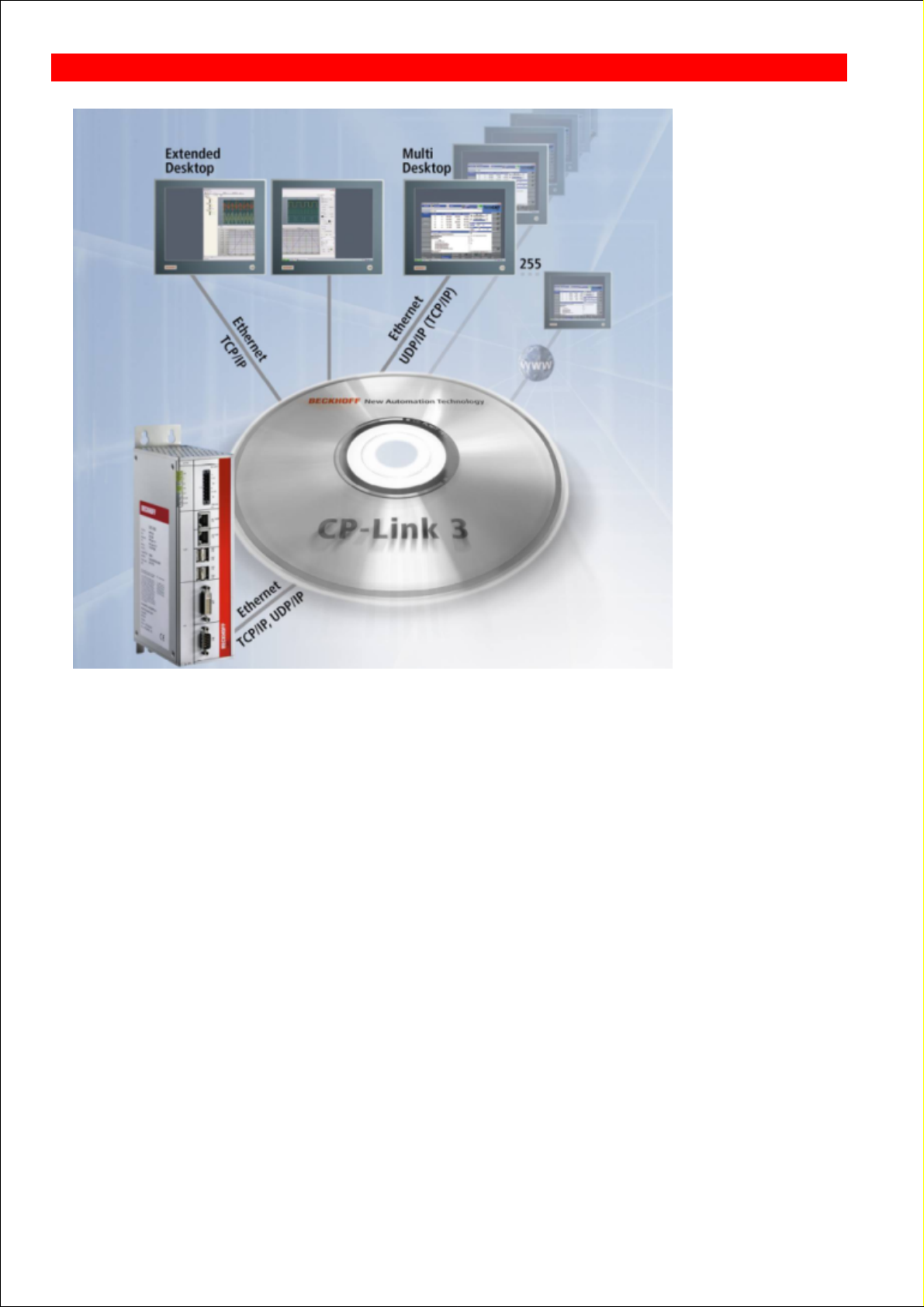
On the one hand, CP-Link 3 transmits the screen content of a host PC over Ethernet to one or more Panel PCs, known
as the CP-Link 3 clients. On the other hand, mouse and keyboard inputs made on the clients are transmitted to the host
PC. The mouse and keyboard inputs from individual clients can be locked, automatically or manually, by the TwinCAT
PLC through a software interface (ADS), so that multiple users do not get in each other's way. Economical standard
Ethernet cables (CAT 5), or Ethernet cables suitable for use in drag chains, can be used to network the devices together.
The scope of delivery for CP-Link 3 includes host and client software. Either Windows 7, Windows XP or Windows XP
Embedded can be installed as the operating system on the host PC. Panel PCs with Windows CE are used as the
clients. Only one CP-Link 3 license is required for each host PC, regardless of the number of clients.
Virtual-USB
USB devices that are connected to a client appear to the host PC as locally connected devices, and can be used in the
usual way. In this way, the keyboard input, touch screen and special key functions of a client are transmitted to the host
PC. It is also possible for USB sticks, USB printers or USB bar code scanners to be connected to a client and used by
the host PC. “Virtual USB” emulates a USB root hub in the host PC. If a USB device is plugged to the client, then the
virtual hub logs the device on to the operating system of the host PC and transparently transmits the ensuing
communication. For the operating system, the USB device behaves as though it was directly connected to the PC.
“Virtual USB” transfers the standards USB 1.1 and USB 2.0. As communication takes place using 100 Mbit/s Ethernet,
the USB 2.0 transmission performance (480 Mbit/s) is restricted.
Communication with the connected USB devices takes place through a normal TCP/IP connection. It is therefore not
possible to guarantee that these devices are queried with a deterministic cycle time. When additional input or output
devices, such as rotary switches, keys and so on, are used on the client it is sometimes necessary for a specific cycle
time to be observed. As an alternative, communication with such devices can take place through an additional
BECKHOFF CP-Link 3: Product overview
Page 7
Page 8
communication channel (RT Ethernet), so ensuring deterministic cycle times.
Virtual Serial Ports
The client's serial interfaces can also be used through a virtual serial port that is created for this purpose on the host PC.
This allows devices with serial interface to be connected to a client, and to be used by applications or by drivers in the
host PC. Communication between the virtual serial interface on the host PC and the actual serial interface on the client
again takes place here over a normal TCP/IP connection.
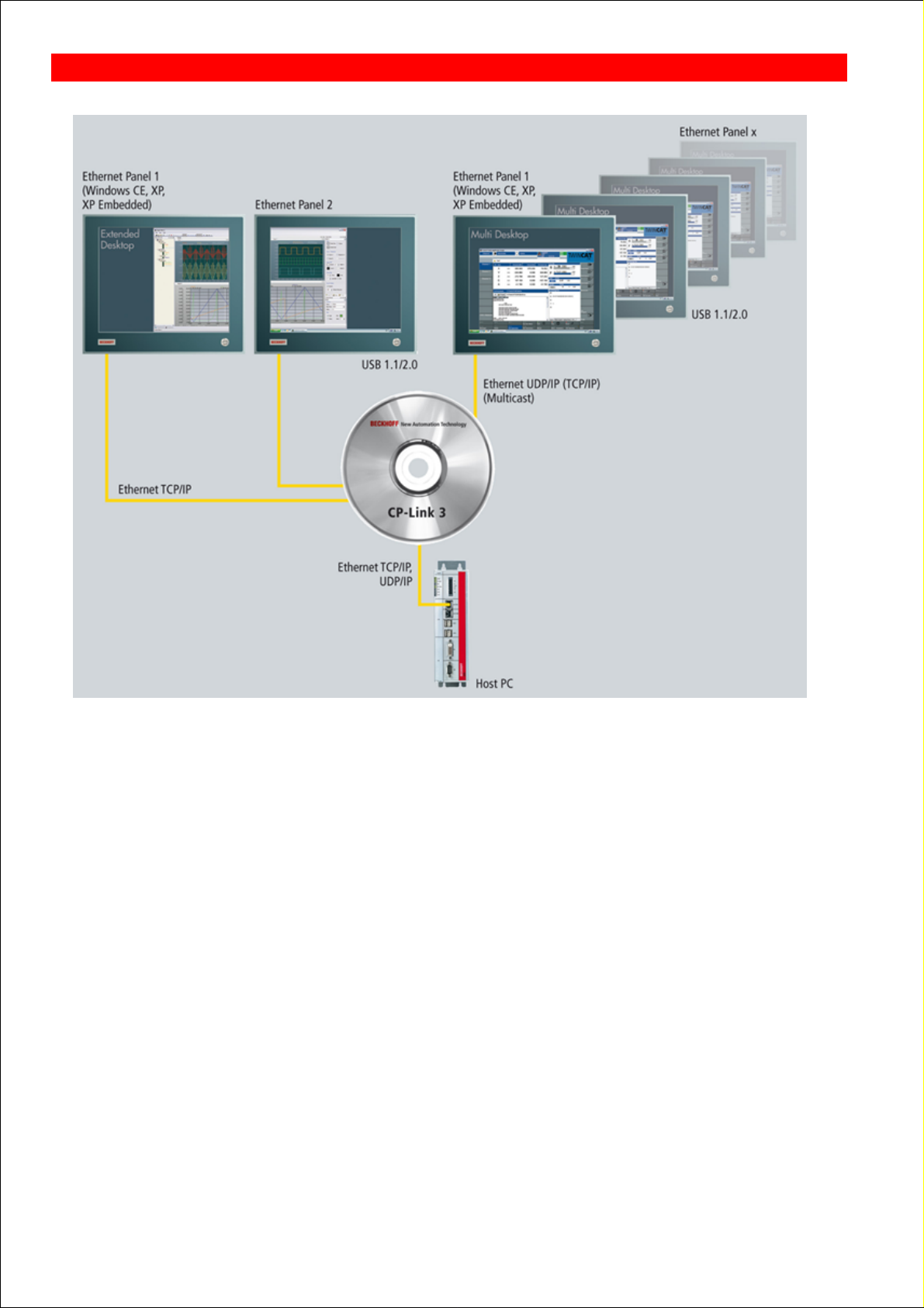
Virtual Graphics
One or more virtual graphic adapters are installed in the host PC in order to transmit the screen contents. There is a
distinction to be made between CP-Link 3 - Mirror Devices and CP-Link 3 - Extended Desktop Devices. A CP-Link 3 Mirror Device captures the screen content from the standard display device, and transmits it to one or more clients. The
standard display device is the one that is used initially when the Windows operating system boots up. A CP-Link 3 Extended Desktop Device extends the host PC's Windows desktop with an additional display device, whose screen
content can be transmitted to one or more clients. An application's program window can be moved to the additional
screens of the extended desktop. A CP-Link 3 client can thus either display the content of any of the CP-Link 3 Extended Desktop Devices or the contents of the standard display device. The contents of other display devices (e.g. of
additional graphics cards) cannot be displayed on CP-Link 3 clients.
The image data may optionally be transmitted via TCP/IP or via UDP/IP (Multicast). The advantage of Multicast is that
data can be transmitted simultaneously to a number of clients, without multiplying the transmitter bandwidth by the
number of receivers.
Note
A maximum of 10 display devices is possible under Windows 7 / Windows XP
The total number of 10 display devices cannot be exceeded, and this includes the
graphics cards installed in hardware, to which one or more display devices, depending
on the type (single or dual head) can be connected. A CP-Link 3 - Extended Desktop
Device corresponds to a single head graphics card, and thus to one display device.
Up to nine CP-Link 3 - Extended Desktop Devices can therefore be installed when a single head graphics card is used. If
a dual head graphics card is used, only eight CP-Link 3 - Extended Desktop Devices can be installed.
Page 8
Page 9

Software variants
CP-Link 3 is available in three variants:
CP-Link 3 single desktop
CP-Link 3 multi desktop
CP-Link 3 extended desktop
The “Virtual USB” and “Virtual Serial Port” functionalities are included in all three variants, and there are no restrictions
on their use. (See also the Functioning section).
The scope of “Visual Graphics” functions varies in the three variants as follows:
CP-Link 3 single desktop: One virtual graphic adapter (Beckhoff CP-Link 3 - Mirror Device) captures the screen
contents from the host PC's standard display device. One client displays the standard display device's image.
CP-Link 3 multi-desktop: One virtual graphic adapter (Beckhoff CP-Link 3 - Mirror Device) captures the screen
contents from the host PC's standard display device. Up to 255 clients display the image of the standard display
device.
CP-Link 3 extended desktop: One or more virtual graphic adapters (Beckhoff CP-Link 3 - Extended Desktop
Devices) are used to expand the host PC's desktop. Up to 255 clients display one of the up to ten different screen
contents. This includes, on the one hand, the image of the standard display device and, on the other hand, the
images generated by virtual Beckhoff CP-Link 3 - Extended Desktop Devices.
BECKHOFF CP-Link 3: Product overview
Page 9
Page 10

Technical data
System Requirements for the Host PC
Hardware
Beckhoff Industrial PC, Beckhoff Embedded PC as
from Intel® Celeron® M ULV 1 GHz
1 GB RAM
Operating system
Windows 7 Professional, Windows 7 Ultimate,
Windows Embedded Standard 7, Windows XP
Professional, Windows XP Embedded or Windows
Embedded Standard
Software
Microsoft .NET Framework 2.0
System Requirements for the Client with Windows CE - (Panel PC / Control Panel)
Hardware
Panel PC: e.g. CP77xx ,CP62xx, CP72xx, CP67xx
Control Panel: CP66xx
64 MB RAM
Operating system
Windows CE 6
with TwinCAT 2.10: Image Version 3.09j or newer
with TwinCAT 2.11: Image Version 3.21j or newer
with TwinCAT 3.1: Image Version 4.00f or newer
Windows Embedded Compact 7
with TwinCAT 2.11: Image Version 5.00l or newer
with TwinCAT 3.1: Image Version 6.00i or newer
System Requirements for the Client with Windows XP / Windows 7
Hardware
Beckhoff Industrial PC, Beckhoff Embedded PC as
from Intel® Celeron® M ULV 1 GHz
1 GB RAM
Operating system
Windows 7 Professional, Windows 7 Ultimate,
Windows Embedded Standard 7, Windows XP
Professional, Windows XP Embedded or Windows
Embedded Standard
General
Transmission medium
Standard Ethernet cable (CAT 5)
Transfer protocol
TCP/IP or UDP/IP
Maximum number of clients:
TCP/IP: 10 clients for each of the host PC's display
devices
UDP/IP: 255 clients for each of the host PC's display
devices
Virtual-USB
Maximum 7 USB devices per client
BECKHOFF CP-Link 3: Product overview
Page 10
Page 11
Installation - Host
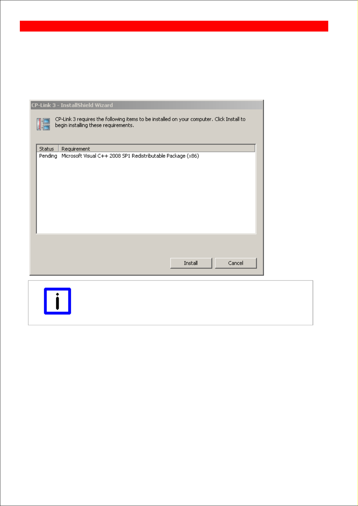
Execute the program CPLink3Setup.exe to start the installation of CP-Link 3. The installation wizard, which will guide you
through the installation process, opens. To begin with, the preconditions for installation are examined; if necessary, a list
of software packages that still have to be installed is displayed. The “Microsoft Visual C++ 2008 SP1 Redistributable
Package (x86)” is included in the setup application, and is installed automatically if necessary. The “Microsoft .NET
Framework 2.0” is not included in the setup application, but can be downloaded by the setup application through an
existing Internet connection. If that is not possible, this step can be skipped for the time being. The “Microsoft .NET
Framework 2.0” - or a newer version - can be installed manually after CP-Link 3 has been installed.
Note
Installation preconditions
The .NET Framework Version 2.0 software - or a newer version - from Microsoft is a
precondition for the installation of CP-Link 3. This software is free, and can be
downloaded from the Microsoft website.
The Installation Wizard then displays a “Welcome” dialog in the next step:
BECKHOFF CP-Link 3: Installation
Page 11
Page 12
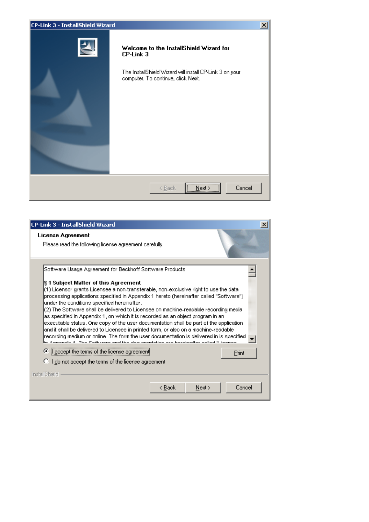
After clicking Next you are asked to declare your agreement with the license conditions:
Click Next , and in the following dialog choose the CP-Link 3 Host Software to be installed. You can change the
destination directory using the Install Location Button.
Page 12
Page 13
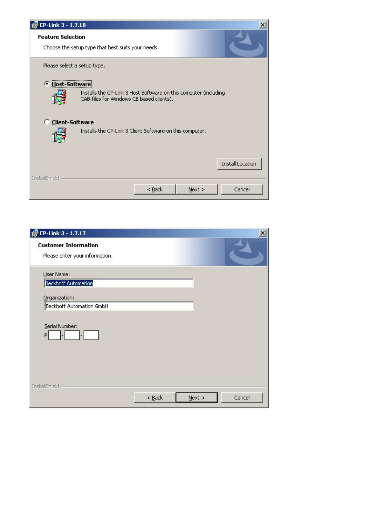
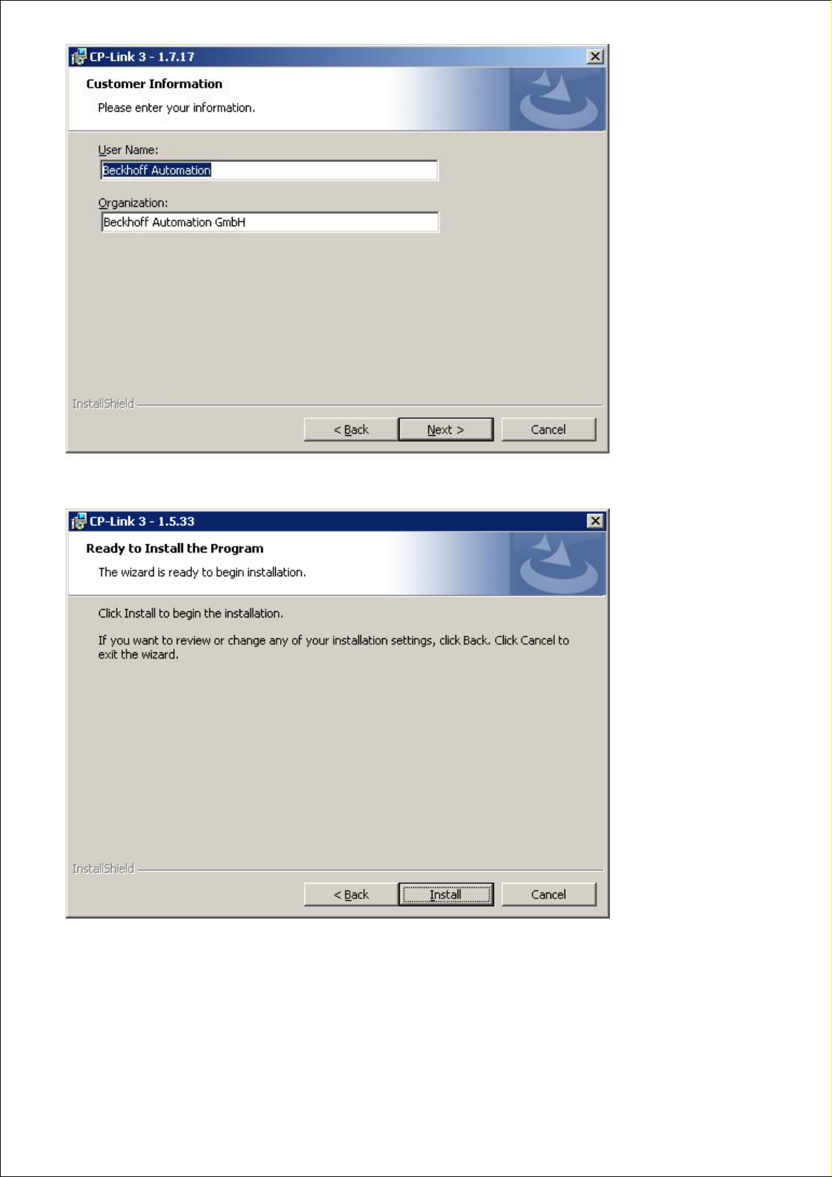
Clicking Next brings you to the dialog where the user data is entered. Complete the fields for the User Name and
Organization , and enter the serial number into the Serial Number field.
Page 13
Page 14
Note
Serial number
You will be given the serial number after you have purchased the CP-Link 3 license.
The serial number contains information about the license level that has been bought.
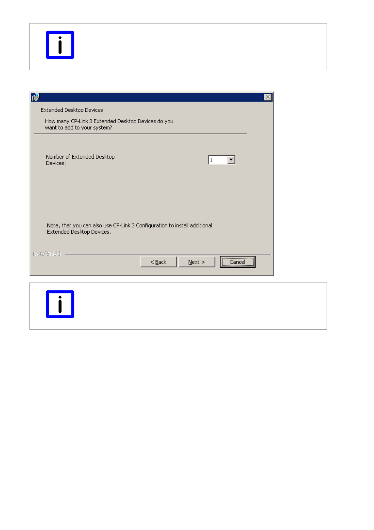
If the Extended-Desktop license level is being installed, you can now specify how many CP-Link 3 - Extended Desktop
Devices are to be installed (see also the Functioning section).
Note
Additional Extended Desktop Devices
Additional CP-Link 3 - Extended Desktop Devices can also be added at any time
through the CP-Link 3 configuration interface (see also the Configuration Interface
section).
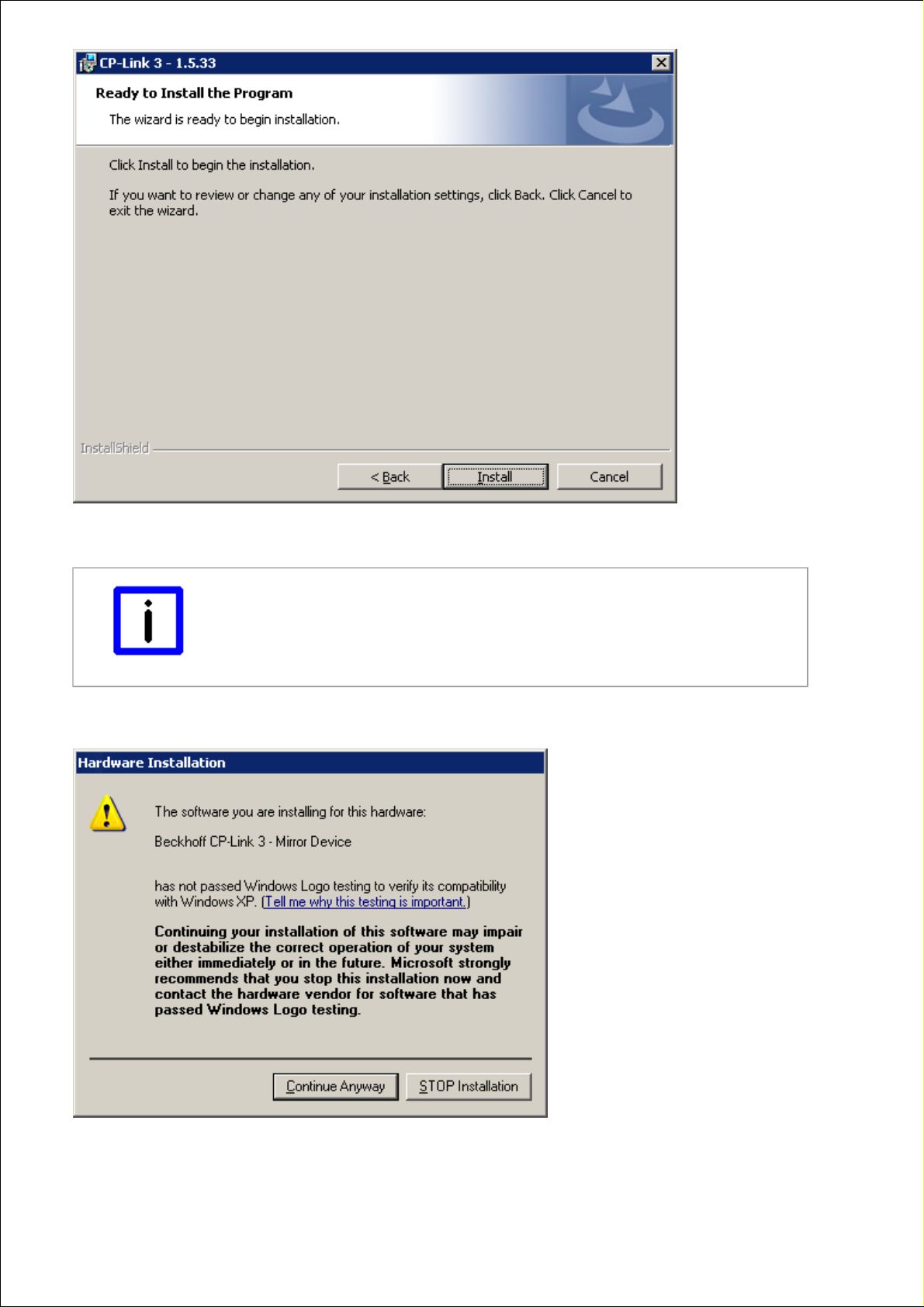
Clicking Next will take you to the final window in the installation routine. If you want to make any changes to your
installation parameters, return with Back , otherwise initiate the installation procedure by clicking Install .
Page 14
Page 15
All the necessary files are now copied into the destination directory, and the required drivers are installed on your
system.
Note
Flickering display
It can take some time to install the drivers. It is possible that the screen will flicker a
number of times during the installation.
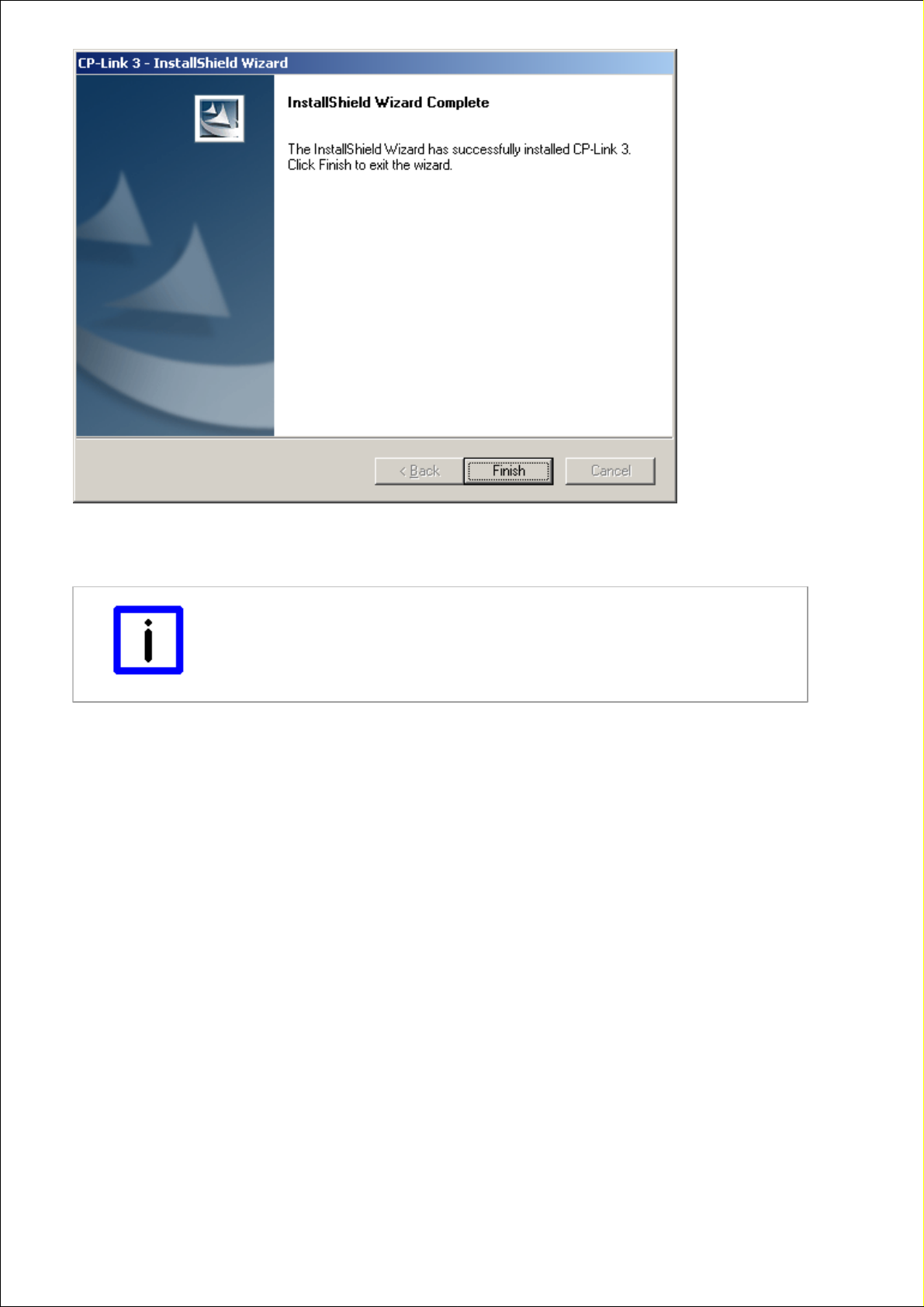
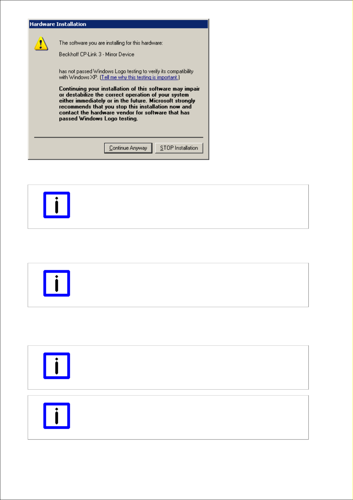
It is possible that multiple messages stating that the “Windows Logo Test” has not been passed for the CP-Link 3
hardware concerned will appear during the installation. Ignore these messages, and click Continue Anyway .
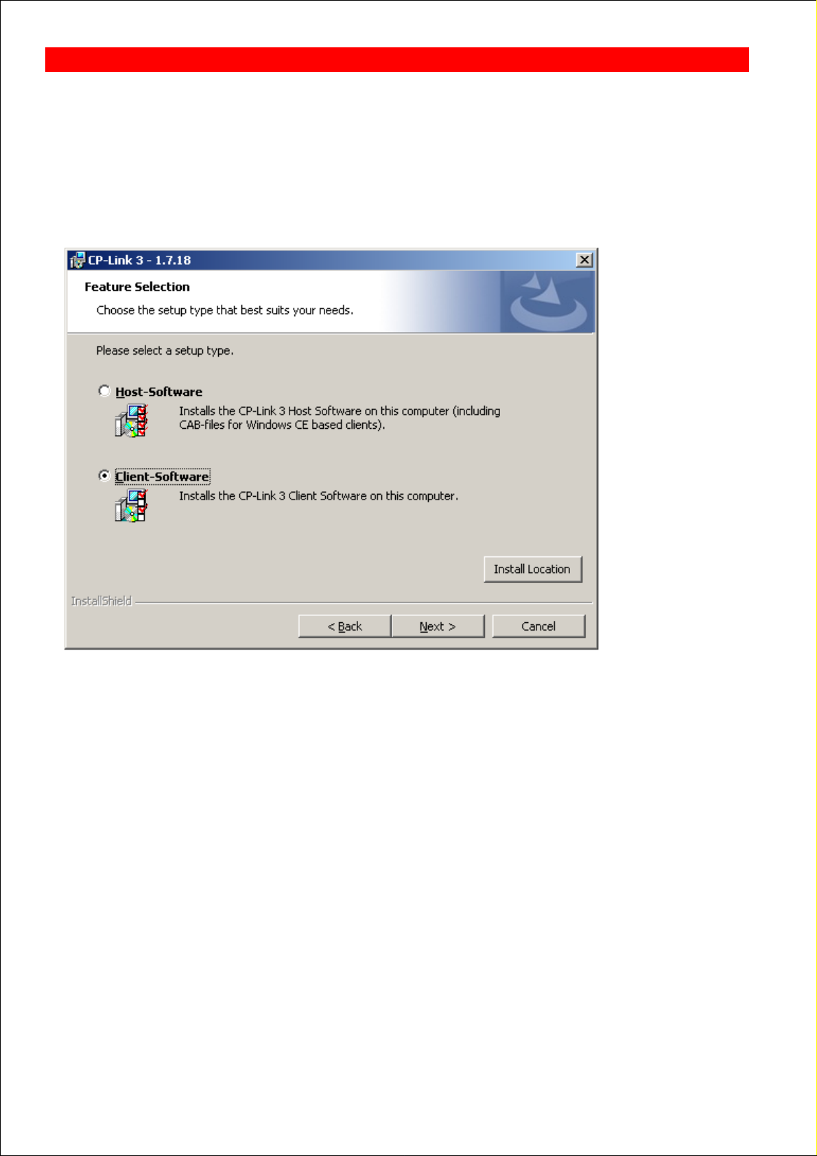
When installation is complete, a success message will appear:
Page 15
Page 16
Click Finish in order to terminate the installation process. After the installation the operating system needs to be
restarted. The necessary software components have now been installed on your computer, and a link to the CP-Link 3
configuration application placed on the desktop.
Note
Replacement of TcUsb.sys - TwinCAT-Installation
Depending on the installed version of TwinCAT and the installation order of CP-Link 3
and TwinCAT it might be necessary to update the driver file TcUsb.sys. (see the Update
of TcUsb.sys section).
Page 16
Page 17
Installation - Client
In addition to the installation of CP-Link 3 on the host PC, CP-Link 3 needs to be installed on the CP-Link 3 clients too.
Installation of client software under Windows 7 / Windows XP
Starting with version 1.5.x of CP-Link 3 the installation program CPLink3Setup.exe contains, in addition to the host
software, the client software for Windows 7 and Windows XP. Execute the program CPLink3Setup.exe on the client PC
to start the installation. Follow the instructions of the installation wizard.
On the next dialog, choose the CP-Link 3 Client Software to be installed. You can change the destination directory using
the Install Location Button.
On the dialog where the user data is to be entered, complete the fields for the User Name and Organization :
BECKHOFF CP-Link 3: Installation
Page 17
Page 18
Clicking Next will take you to the final window in the installation routine. Initiate the installation procedure by clicking
Install .
It is possible that multiple messages stating that the “Windows Logo Test” has not been passed for the CP-Link 3
hardware concerned will appear during the installation. Ignore these messages, and click Continue Anyway .
Page 18
Page 19
When installation is complete, a success message will appear. If you finish the installation program, you will be asked to
restart the computer.
Note
Client PC initially not operable
The client PC is initially not operable as long as it waits for a connection with a CPLink 3 host. If no host connects with the client, it becomes operable after about one
minute. The client indicates this state with an info box.
Installation under Windows CE
The subfolder "CE\X86" or "CE\ARM" in the program directory on the host PC contains the installation files for Windows
CE based clients.
Note
Windows CE 6 and particular image version required
Please note the requirements listed under System Requirements for the Client with
Windows CE (see the Technical data section).
The corresponding CE-cab installation file needs to be copied to the CE device first (via memory stick / FTP / Public
Folder / ...). Double click the cab file on the CE device to start the installation and follow the instructions of the installation
wizard. In order to ensure correct functioning of CP-Link 3, always install CP-Link 3 into the directory suggested by the
installation wizard. After installation has finished the cab file will be deleted automatically.
Note
Installation directory
In order to ensure correct functioning of CP-Link 3, always install CP-Link 3 into the
directory suggested by the installation wizard.
Note
CE-cab file will be deleted automatically after installation completes
After installation has finished the cab file will be deleted automatically. Therefore you
should always transfer a copy of the original cab file to the client.
Page 19
Page 20

Note
CE device initially not operable
The CE device is initially not operable as long as it waits for a connection with a CPLink 3 host. If no host connects with the client, it becomes operable after about one
minute. Starting with version 1.1.19 of CP-Link 3 the client indicates this state with an
info box.
Color depth adjustment
To maximize the performance of CP-Link 3 Virtual-Graphics , the color depth of the client's display should match the
color depth of the corresponding host display. Normally, the client's color depth has to be set to 32 bit.
Adjustment of the color depth under Window CE:
The platform specific directory "\Hard Disk\Regfiles\Samples\Cxxxx" contains registry files with which the color
depth of the client can be adjusted. Note, that the settings from registry files can be written to registry by a double
click on the file in the Windows CE Explorer.
Alternatively, the color depth can be adjusted via the program CX Configuration on the tab Display Settings.
Page 20
Page 21

Uninstallation
Uninstallation of the host software or the client software under Windows 7 / Windows XP
To remove CP-Link 3 from a PC, go to Start -> Control panel -> Add or Remove Programs (Windows XP), or Start ->
Control Panel -> Programs and Functions (Windows 7) and select Remove for the CP-Link 3 software package. The
installation wizard, which will guide you through the uninstallation process, opens.
Clicking Yes will remove CP-Link 3 from the computer.
BECKHOFF CP-Link 3: Installation
Page 21
Page 22
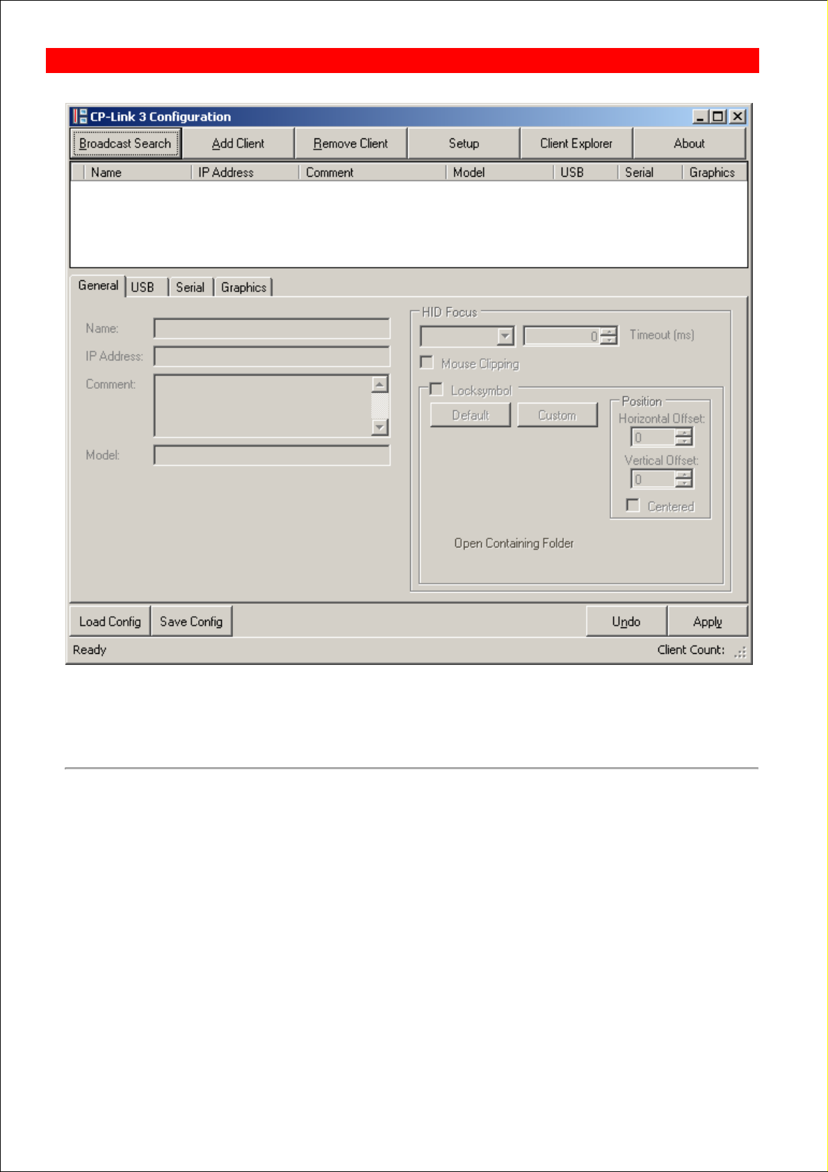
Configuration interface
The client list, which is still empty, is located in the upper part of the configuration interface, while the settings for marked
clients will later be listed in the lower part.
Editing the client list and configuring the clients are described in the sections on Edit the client list and Client
configuration .
Setup
Clicking Setup opens a dialog which, amongst other things, allows the user to adjust the resolution, color depth and
position for all display devices. Furthermore, additional CP-Link 3 - Extended Desktop Devices can be
installed/uninstalled:
BECKHOFF CP-Link 3: Configuration
Page 22
Page 23
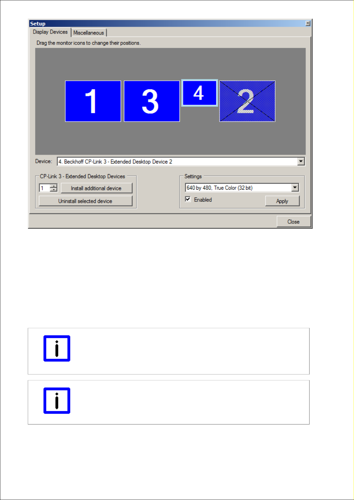
Display Devices
A display device is selected by clicking on a monitor symbol, as can be seen from a light blue border. Similarly, a display
device can also be chosen from the selection list (Device ) shown on the dialog. The settings for the selected display
device can now be modified in the lower part (Setting) of this dialog. The position of the monitor icons can be adjusted by
drag-and-drop. Clicking Apply will activate the changes.
Installation/uninstallation of CP-Link 3 - Extended Desktop Devices:
In the CP-Link 3 - Extended Desktop Devices area it is possible to enter the number of Extended Desktop Devices that
are to be installed, and the installation can be started by clicking Install additional device(s) . It may be necessary to
restart the operating system after the installation process.
After selecting a CP-Link 3 - Extended Desktop Device the device can be uninstalled by clicking Uninstall selected
device . After the uninstallation process the operating system needs to be restarted.
Note
A maximum of 10 display devices is possible under Windows 7 / Windows XP
The total number of 10 display devices cannot be exceeded, and this includes the
graphics cards installed in hardware, to which one or more display devices, depending
on the type (single or dual head) can be connected. A CP-Link 3 - Extended Desktop
Device corresponds to a single head graphics card, and thus to one display device.
Note
Check the license level
You must be licensed to the appropriate level (Extended-Desktop) in order to
install/uninstall Extended Desktop Devices.
Miscellaneous
Page 23
Page 24
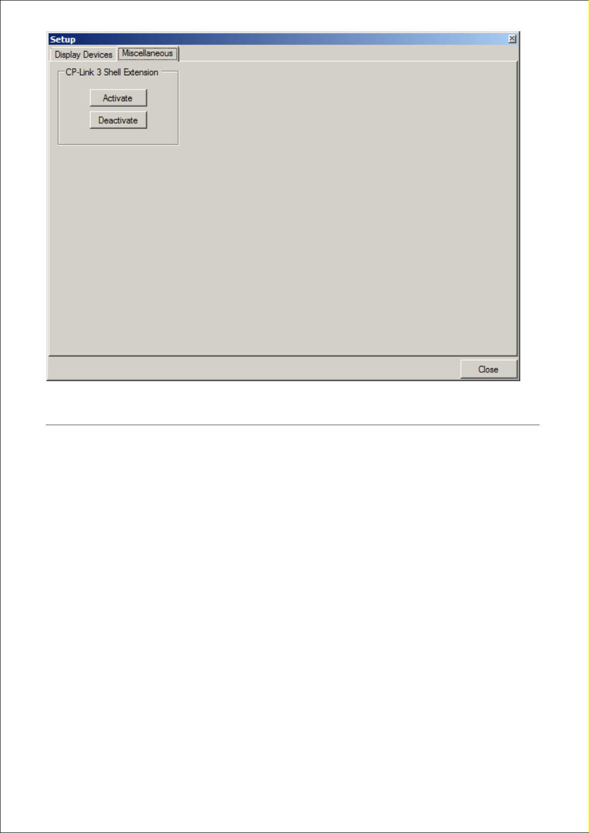
The CP-Link 3 Shell Extension can be switched on or off in the CP-Link 3 Shell Extension area. The CP-Link 3 Shell
Extension is used to extend the desktop context menu (see also the CP-Link 3 Shell Extension section).
About
Clicking About opens a window that displays the current license and version information about the CP-Link 3 software
installed on the computer.
Page 24
Page 25

Clicking OK closes the information window.
Page 25
Page 26

Edit the client list
The configuration interface appears with an empty client list the first time that CP-Link 3 Configuration is started:
Clients can be added to the client list by clicking Broadcast Search or on Add Client . Clients can be removed from the
client list with a click on Remove Client .
Note
Activate the settings with Apply
The procedure must be completed by clicking Apply in order to finally write the changes
into the client list.
Broadcast Search
The Broadcast Search function makes it possible to search automatically for devices in the network that are CP-Link 3capable. Devices found by the Broadcast Search can be adopted into the client list.
Note
Windows Firewall
If the Windows Firewall is enabled, the UPnP service must be authorized in the
Windows Firewall if automatic searching for CP-Link 3-capable devices is to work.
BECKHOFF CP-Link 3: Configuration
Page 26
Page 27

If it is necessary to make modifications in the Windows Firewall, the following dialog will appear when clicking on the
Broadcast Search button:
The UPnP service is authorized in the Windows Firewall by clicking Yes . Clicking No will leave all the Windows Firewall
settings unchanged, as a result of which it will not be possible to search through the Broadcast Search .
If the Windows Firewall is properly configured, then clicking the Broadcast Search button will open the CP-Link 3
Broadcast Search window. A click on Start Search in the Broadcast Search window will start the search for UPnP devices
in the network:
The desired device can be added by clicking the Add button or by double-clicking, and will then appear in the client list.
Whether or not the IP address of the new device is already present in the client list is checked when a client is added. If
it is, a dialog opens through which the action can be cancelled or the client overwritten.
If clients have just been added to the client list, they remain marked in green in the status field in front of the client name
until the changes have been adopted by clicking Apply .
Page 27
Page 28

Add Client
If a client is not yet present in the network, or is not UPnP-capable, it can be added manually by means of Add Client :
Page 28
Page 29
When a client is added through Add Client , standard settings for the Name , the IP Address and the Comment are
loaded. These settings may need to be modified.
If clients have just been added to the client list, they remain marked in green in the status field in front of the client name
until the changes have been adopted by clicking Apply .
Remove Client
Remove Client can be used to delete clients from the client list.
Page 29
Page 30
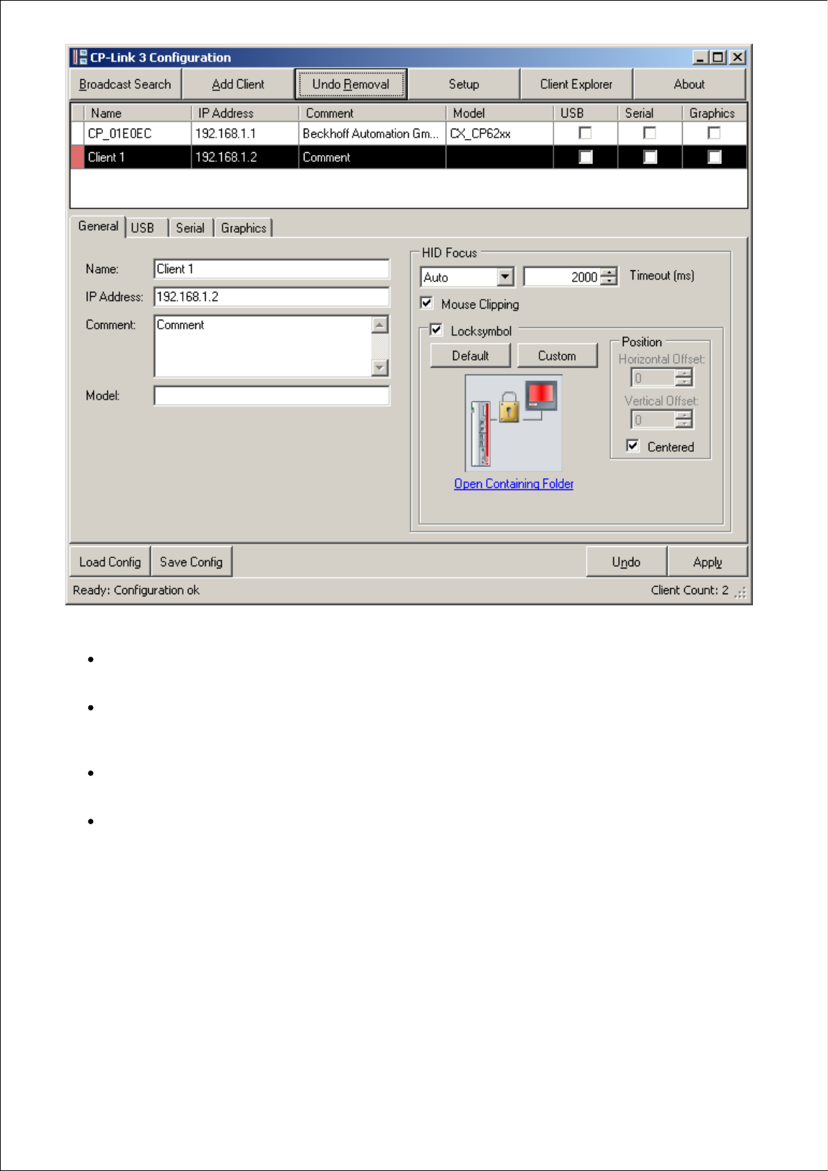
The labelling and the behaviour of the button depends on the colour of the status field for the selected client:
The status field is coloured green (the button is labelled Remove Client ):
The client will be removed immediately from the client list by clicking Remove Client .
The status field is coloured white (the button is labelled Remove Client ):
The status field is coloured red until the change is adopted by clicking Apply. Only then is the client finally
removed from the client list.
The status field is already coloured red (the button is labelled Undo Removal ):
The removal mark will be removed by clicking on the button again.
The status fields of a number of selected clients have different colours (the button is labelled Toggle Removal
Marks ):
Clients that are green will be removed immediately from the client list, clients that are marked in red will have their
removal mark removed, while the status field for clients whose status field is white will turn red.
If clients are to be removed from the client list, and if they are marked red in the status field in front of the client name,
the changes will not finally be adopted till Apply is clicked.
Page 30
Page 31

Client Configuration
The configuration of a client is divided into four parts, which are described in detail below:
General - a client's general parameters.
USB - settings for "Virtual USB".
Serial - settings for "Virtual Serial Ports".
Graphics - settings for "Virtual Graphics".
The CP-Link 3 functionalities (Virtual USB, Virtual Serial Ports and Virtual Graphics) can be enabled or disabled
separately for each client. This is either done through the appropriate selection boxes in the client list, or through the
selection box on the corresponding tab in the lower part of the configuration window.
In order to configure one or more clients they must first be selected. This is done simply by clicking them in the client list.
It is also possible to select multiple clients simultaneously. In this case the most recently marked client has a black
background, while the others all have blue backgrounds:
The settings displayed are always those for the most recently marked clients, while changes that are made are carried
out on all the clients that have been selected.
General
BECKHOFF CP-Link 3: Configuration
Page 31
Page 32

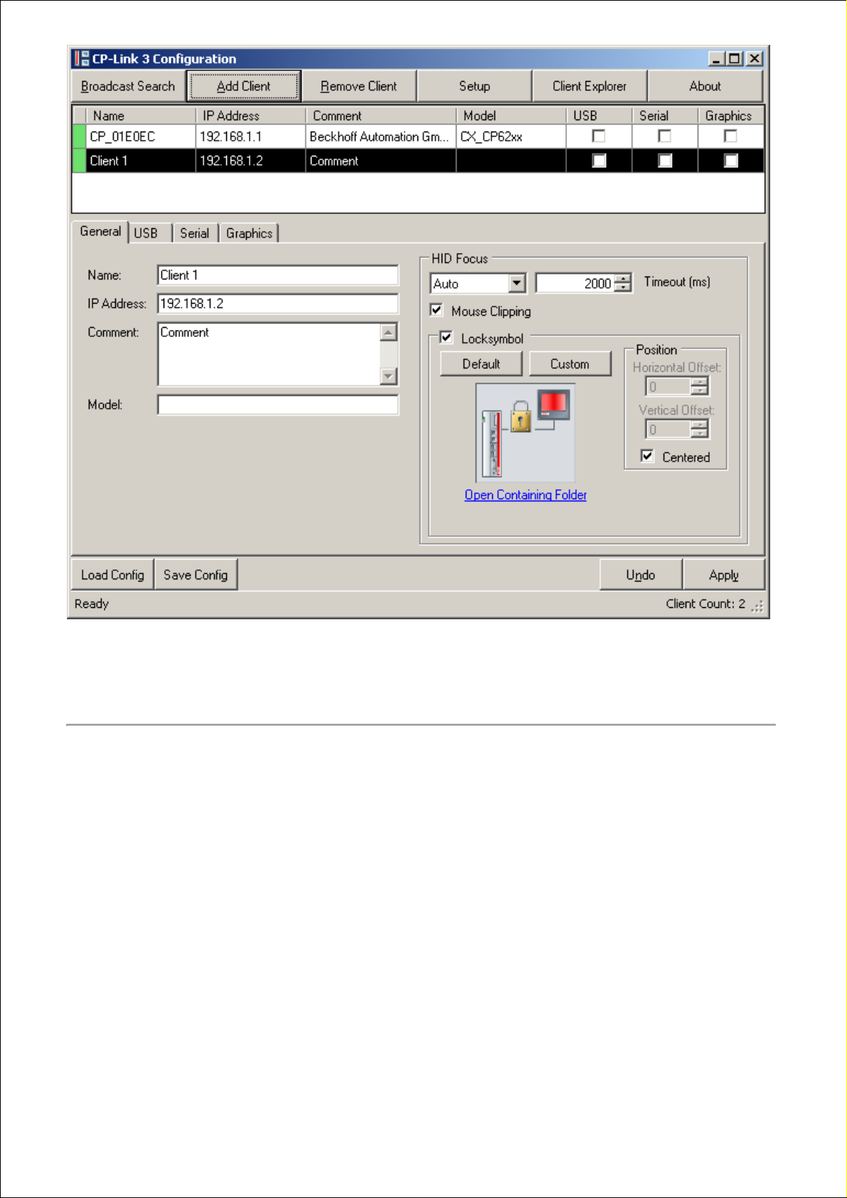
The general parameters for a client are set on the General tab. An asterisk next to the name of the tab indicates that the
settings for the “General” section have been changed, but have not yet been activated with Apply .
The general parameters of a client include the IP address along with a name and description, as well as the settings of
the HID focus. The IP Address entry is essential. In addition, entries can also be made in the Name, Comment and
Model fields. Any name can be assigned to the client in the Name field. The name does not have to correspond to the
client's computer name.
Note
Automatic entry of the IP address
If a client is added to the client list through the Add Client function, the client's IP
Address field is automatically pre-filled. It may be necessary to modify this entry!
HID focus
The client's input behavior can be configured with the aid of the HID focus (i.e. the human input device focus):
When a client has the HID focus, only this client is able to make input to the host through a keyboard, mouse or
touchpad. Input from all the other clients is blocked. There is a difference between the auto and manual modes of the
HID focus.
Auto HID focus - If an input is made at a client, it automatically acquires the HID focus. If no further input is made
for the set period of time, the client loses the HID focus again. The period can be specified, in milliseconds, in the
Timeout field. If the timeout is set to 0, the HID focus will not be set by making inputs, which means that inputs
can be made simultaneously at other clients too.
Manual HID focus - Input from the client is initially blocked. The HID focus must be given to the client before
inputs can be made. There is a software interface, described under Set the HID focus manually , for this purpose.
When manual mode is selected, the timeout is automatically set to 0 ms, and this means that it is necessary to
reset the HID focus explicitly in all cases. If the timeout is anything other than 0 ms, then the manually set HID
focus will automatically be reset after the given time if no further input is made.
If MouseClipping is active (which is the standard setting), the mouse pointer cannot leave the screen area of the client
that has the HID focus. This prevents accidental operations in windows that are outside the visible area of the desktop.
Lock symbol
The graphical Locksymbol is shown on any clients that are unable to make inputs. This allows a user to see that the HID
focus is already assigned to another client.
The standard default lock symbol can be set by means of the Default button. It is also possible to select any other
graphical symbol, modified to meet particular requirements, to represent the lock. The Custom button opens a file dialog
with which the file that is to be used can be selected. By clicking Open Containing Folder underneath the preview of the
lock symbol, an Explorer window that shows the storage location of the selected lock symbol can be opened.
Note
Condition of the lock symbol image
The size of the lock symbol image is limited to a maximum of 256 x 256 pixels. Bigger
images will be shrunken to the size of 256 x 256 pixels, smaller images will keep their
original size.
Images with transparencies are supported.
Position:
By default, the lock symbol will be shown centered on the client's display.
Page 32
Page 33

By clearing the tick in the Centered selection box a vertical and horizontal offset can be specified by using the Horizontal
Offset and Vertical Offset fields. The offset's origin is the upper left corner of the host display's screen content shown on
the client.
USB
A client's settings for the “Virtual USB” area are made on the USB tab. An asterisk next to the name of the tab indicates
that the settings for the “Virtual USB” section have been changed, but have not yet been activated with Apply .
Page 33
Page 34

The “Virtual USB” functionality for the client can be enabled or disabled by setting or clearing the tick in the USB
selection box.
Note
Found new Hardware "Beckhoff GmbH USB Control Panel CP6800"
After the first activation of "Virtual-USB" for a client the "Found new Hardware Wizard"
appears indicating that the Hardware "Beckhoff GmbH USB Control Panel CP6800" has
been found. This is actually the internal USB Bus Coupler which requires the driver
TcUsb.sys. This driver is available on Beckhoff PCs and will be installed automatically
by the hardware wizard.
USB Device Filters
Device Blacklist
The Device Blacklist is a list of filters. Each entry in the Blacklist is a filter representing a specific group of USB devices
that the host PC is going to ignore (see also the USB Device Filter Lists section).
Device Whitelist
The Device Whitelist is a list of filters. Each entry in the Whitelist is a filter representing a specific group of USB devices
that the host PC is not going to ignore even though the device has a matching entry in the Blacklist (see also the USB
Device Filter Lists section).
Device Use Local List
The Device Use Local List is a list of filters. Each entry in the Use Local List is a filter representing a specific group of
USB devices which are to be used locally by the client (see also the USB Device Filter Lists section).
Page 34
Page 35

Note
Displaying device filters
If more than one client has been selected, then the list entries are only displayed if all of
the selected clients have the same list entries.
Editing USB device filters
The procedure for editing USB device filters is similar for all types of filter lists:
Filters for USB devices can be added or removed through the Add and Remove buttons. Clicking the Edit button allows
filters that have already been created to be edited. Alternatively, you can use the context menu to add, remove or edit
filter entries. In addition you can use the context menu to paste an entry from the clipboard if you previously copied an
entry to the clipboard using the Client Explorer (see also the Client Explorer section).
The dialog for adding or editing filters (Add or Edit ) has the following structure:
Hexadecimal notation (in which 0x can be omitted) is typically used for the entries in these fields. It is also possible to
select a predefined class of devices (e.g. Mass Storage ), and to enter this into one of the lists.
It is, for instance, possible to quote the ID of the vendor (Vendor ID). In case of an entry for the Blacklist entry this will
cause the host PC to ignore any USB devices with this vendor ID. The host PC can, similarly, ignore all devices with a
defined product ID, class, subclass or protocol.
Page 35
Page 36

Note
View USB Device Filter in Client Explorer
The Client Explorer can be used to check what kind of device filters have been
configured for a particular device or rather the way the device can currently be used.
The Client Explorer shows the current status for every USB Device (see also the Client
Explorer section).
Editing the Device Use Local List
Up to version 1.4.x of CP-Link 3 the Device Use Local List has been configured by editing the registry on the client itself
(see also the Using USB devices locally on the client section). Starting with Version 1.5.x of CP-Link 3 the configuration
is done on the host PC. If the client already has had Use Local List entries, they are displayed on the Device Use Local
List tab:
By setting the tick in the Ignore on Client selection box, the client-side configured Use Local List entries are ignored and
it is paid attention to the Use Local List configured on the host PC only.
Clicking the Show / Import to Configuration button shows a list of the client-side configured Use Local List entries:
By using the Import button the selected client-side configured Use Local List entries are being adopted to the list
configured on the host PC.
Serial
A client's settings for the “Virtual Serial Ports” area are made on the Serial tab. An asterisk next to the name of the tab
indicates that the settings for the “Virtual Serial Ports” section have been changed, but have not yet been activated with
Apply .
Page 36
Page 37

The “Virtual Serial Ports” functionality for the client can be enabled or disabled by setting or clearing the tick in the Serial
selection box.
A port name can be chosen in the selection box under Com Port of Client and can be added to the port list with Add . It
should be noted that only client serial ports that actually exist can be used. The currently selected entry can be deleted
from the list with Remove .
Apply activates the configuration. The first time this is done for a client, the CP-Link 3 Remote Serial Port Enumerator is
installed first, and then the CP-Link 3 Virtual COM Port driver for each virtual interface. In each case, the installation is
done using the “Found New Hardware Wizard”. The virtual interfaces only appear when the TCP/IP connection to the
client is established.
The current status of the virtual serial interfaces is read and displayed in the list with Refresh . In particular, the list shows
the mapping between COM Ports of the Client (COM Port of Client ) and the virtual COM Ports on the Host (COM Port on
Host ).
The port names are usually found at the associated device terminal. Serial devices that are connected internally, such as
a serial touchscreen, are documented in the device description (e.g. a label on the rear of a Panel PC).
Note
COM port must be available
A virtual COM port can only be installed when a connection to the client does in fact
exist and the port is available.
Elo touch panel
Page 37
Page 38

An Elo touch panel, connected serially, can be operated through a virtual serial interface. The appropriate Elo-Touch
driver has to be installed for the selected port. For this purpose, start the installation application EloSetup.exe and follow
the instructions of he installation wizard.
Graphics
A client's settings for the “Virtual Graphics” area are made on the Graphics tab. An asterisk next to the name of the tab
indicates that the settings for the “Virtual Graphics” section have been changed, but have not yet been activated with
Apply .
The “Virtual Graphics” functionality for the client can be enabled or disabled by setting or clearing the tick in the Graphics
selection box.
The diagram on the left shows all the display devices available on the host PC, indicated by the monitor symbols. One of
the display devices listed can be assigned to one client, which means that this client should show the screen contents of
the assigned display device. The assigned display device becomes green, while all the other display devices are shown
blue. If a display device is inactive, this is shown by cross-hatching. A monitor symbol that is crossed through indicates
those display devices that can not be assigned to a client. Such devices include, for instance, additionally installed
graphics cards, or the second output of a dual-head graphics card (see also the Functioning section).
Assignment of a display device to a client
The display device is first selected by clicking on a monitor symbol, and this can be seen from the light blue border.
Similarly, a display device can also be chosen from the selection list (Device ) shown at the top right. The selected
device can now be assigned to the client by clicking Use Selected Device for Client or through a right click on the
selected display device. The assigned display device is emphasized in green.
Page 38
Page 39

Note
Assigning the display device
The first time that the “Virtual Graphics” functionality is enabled, the first display device
is automatically assigned to the client.
Resolution of the display device on the host / resolution of the client
The resolution and the color depth for the currently selected display device are shown on the right next to the diagram. If
changes to these parameters are desired, this is to be done through the Setup Dialog (see also the Configuration
interface section - Setup). Under Windows XP changes can also be done via the Windows display settings (see also the
section on Windows Display Settings ).
If the resolution of an assigned display device differs from the resolution of the associated client, the display behavior of
the client can be modified by setting or clearing the tick in the Fit to Client Screen Size box:
Fit to Client Screen Size not set:
If the resolution of the assigned display device is lower than the resolution of the client, the contents of the screen
are centered (with a black outline) on the client. If, on the other hand, the resolution of the assigned display device
is larger than the resolution of the client, the upper left-hand portion of the screen contents are displayed on the
client.
Fit to Client Screen Size set:
If the resolution of the assigned display device is lower than the resolution of the client, the contents of the screen
are enlarged and displayed using the whole of the client's screen. If the resolution of the assigned display device
is higher than the resolution of the client, the contents of the screen are shrunk and displayed using the whole of
the client's screen. The settings for the resolutions of all the devices involved are not changed by this. Only the
image that is to be displayed is appropriately enlarged or shrunk.
Note
Quality of the displayed image
If the enlargement or reduction ratios are not integers, the enlargement or reduction can
have negative effects on the quality of the displayed image.
Transfer protocol for graphical data - Connection Settings
The protocol used to transfer graphical data can be set separately for each client. Data transmission via TCP is preset by
default. If TCP has been selected, graphical data is sent separately to every single client. This multiplies the data rate by
the number of clients. If, on the other hand, data transmission via UDP (UDP-Multicast) has been selected for one or
more clients, that means that the graphical data associated with the display device is transmitted over the network once ,
and all the clients that are assigned to this display device, and where data transmission via UDP has also been set, can
receive this data.
Data transmission via UDP thus has the advantage that the network bandwidth used is reduced to a minimum. A
disadvantage of data transmission via UDP, as compared with data transmission via TCP, is a higher susceptibility to
interference. In the event of a faulty transmission via UDP, it therefore follows that it is helpful to select TCP as the
transfer protocol. Because, however, this multiplies the bandwidth used by the number of clients, this can have a
negative effect on performance. This will happen if the required bandwidth is greater than the bandwidth that is available.
In cases of this sort, the performance of all the CP-Link 3 functionalities (Virtual USB, Virtual Serial Ports, Virtual
Graphics) are affected.
Page 39
Page 40

Client Explorer
The CP-Link 3 Client Explorer is a tool for monitoring the function of CP-Link 3. Warnings, error messages and status
information of the various CP-Link 3 components are shown in Client Explorer.
The Client Explorer user interface is laid out as follows:
The upper section pictures a tree structure, which on one side shows the currently activated CP-Link 3 Configuration and
on the other contains current status information. In the lower section is a message window in which warnings, error
messages and status information is given in the form of text.
Hierarchy of the tree structure:
1. Each of the nodes in the first level corresponds to a client:
The node text contains the client's name and IP address according to the current configuration.
2. The nodes in the second level correspond to the CP-Link 3 components "Virtual USB", "Virtual Serial Ports“ and
"Virtual Graphics" of the client, where a node is only depicted for those components activated in the configuration. At the
same time the icon of such a node gives information on the current status of the component:
BECKHOFF CP-Link 3: Function monitoring
Page 40
Page 41

- The component has no network connection. The host PC is attempting to connect to the client.
- The component is in an invalid or an error state. In this case a corresponding message is shown in the
message window (see below).
Network connection has been established with the component, the component is in the initialization
phase.
Network connection has been made with the component and the initialization phase has been
successfully completed.
Network connection has been lost with the component, the component is in the de-initialization phase.
The component has been removed from the configuration and is in the de-initialization phase.
3. Third level nodes contain detailed information on the corresponding component.
3.1 Nodes underneath a USB node: Each node represents a USB device which is plugged in at the client. The node text
contains product description read from the device (if available) on one side and on the other the device class. The icon of
such a node gives information on the current USB device status :
The client’s USB device can be used on the host PC via "Virtual USB".
The client’s USB device could be used via "Virtual USB" on the host PC, the usage is however blocked
by the host PC configuration. There is a matching entry for this device in the USB Device Blacklist (see
also the USB Device Filter Lists ).
The client's USB device can be used on the host PC via "Virtual USB", there is a matching entry for this
device in the USB Device Blacklist as well as in the USB Device Whitelist (see also the USB Device
Filter Lists ).
The client’s USB device cannot be used on the host PC via "Virtual USB", as the device is being used
locally on the client. There is a matching entry for this device in the USB Device Use Local List (see also
the USB Device Filter Lists ).
Each USB device node has further sub-nodes which contain detailed information (manufacturer, serial number, etc.) on
the USB device.
Right clicking a USB device opens a context menu with which you can add the selected device to one of the USB device
filter lists of the configuration (see also the Client Configuration section or the USB Device Filter Lists section):
If you copy the device information into the clipboard (Copy to clipboard ) you can paste the copied information in the
configuration window in order to create a device filter entry (see also the Client Configuration section - Edit USB device
filters).
If the node represents a USB Bus Coupler , one of its sub-nodes indicates the Coupler's device number. Depending on
the type of the Bus Coupler, the device number can also be changed. The device number can be changed for all Bus
Couplers of the type CPx8xx. Right clicking the device number sub-node opens a context menu with which you can open
the dialog for changing the device number.
Page 41
Page 42

In the dialog the device number can be edited. The new value is transmitted by clicking the "Change" button. By clicking
the "Cancel" button the process can be canceled.
The USB Bus Coupler-Number can alternatively be changed with the TwinCAT System Manager (see also the Using the
CPx8xx USB Bus Coupler -Section).
3.2 Nodes underneath a serial node: Each node represents a serial interface of the client which can be used on the host
PC via "Virtual Serial Ports".
The node text contains the name of the virtual serial interface created on the host PC and the name of
the corresponding client's serial interface.
The message window:
In the message window status information and error messages are shown sorted by time. Each entry has a field for the
timestamp, a field for the client to whom the message does apply, a field for the component of the corresponding client
and a field for the message itself. Error messages are highlighted in red.
Right clicking on the header of the output field opens a menu which is used to choose which components of the
messages should be shown or not shown.
Above the output field are several selection boxes which allow different filters to be defined. These filters determine
which messages are shown or not shown in the output field. Filtering can be done using any combination of the following
criteria:
Filtering on messages of certain clients: Depending on the selection either the messages of all clients ( All Clients )
or the messages of the clients selected in the tree structure (Only Selected Client ) are shown. By default the
messages of all clients are shown.
Page 42
Page 43

Filtering on messages of certain components: The messages of the selected components are shown. By default
the messages of all components are shown.
Filtering on messages of certain type: Depending on selection either all messages (error and info messages) or
only error messages are shown. By default all messages are shown.
There are further buttons on the right next to the selection boxes for the message filters:
Autoscroll On/Off - If Autoscroll On is selected and a new entry is inserted into the message window, the contents
of the window are scrolled so that the new message appears in the visible part of the message window. If
Autoscroll Off is selected, automatic scrolling is turned off, in other words the contents of the window are not
scrolled for a new entry.
Copy - All marked messages are copied into the clipboard.
Clear All - All messages are deleted.
Page 43
Page 44

Network Topology
Concerning the usage of CP-Link 3 please note the following:
It is recommended to use a separate network for CP-Link 3.
The PCs used in the network have to be connected together using tree structure, i.e. clients are connected to the
host PC either directly or via one or several switches. Ring structures, bus structures or serial structures (daisy
chaining) are not possible.
The maximum length of the network cable between two PCs or switches is 100 m.
If a host PC uses the USB Bus Couplers built into the clients via RT-Ethernet, it might be necessary to use a
separate network for RT Ethernet (see also Using the CPx8xx USB Bus Coupler ).
BECKHOFF CP-Link 3: Miscellaneous
Page 44
Page 45

Configuration of RT Ethernet devices
By installing the special TwinCAT Intel PCI Ethernet Adapter driver, a network adapter is turned into an RT Ethernet
adapter. Installation is done with the TwinCAT System Manager using the “Options|Show Real Time Ethernet Compatible
Devices ...” dialog.
Note
CP-Link 3 and RT Ethernet
If the same network adapter is used for CP-Link 3 as for RT Ethernet under certain
conditions this can lead to connection losses (see Comments chapter or
Troubleshooting ). In addition, graphical data must be sent over TCP/IP, since the
client's RT Ethernet adapters do not accept UDP Multicast packets (also see Client
Configuration ).
Adding an RT Ethernet device to the I/O Configuration
An RT Ethernet device can be added to the I/O Configuration with "Append Device". On the Adapter tab the RT device is
associated with an RT Ethernet adapter. The cycle time of the RT Ethernet device is specified indirectly through linking
the DevState variable with a task variable. The cycle time of the task then defines the cycle time for the RT Ethernet
device.
The following illustration shows an I/O Configuration for a host PC with one RT Ethernet device:
The following illustration shows an I/O Configuration for a client with one RT Ethernet device:
BECKHOFF CP-Link 3: Miscellaneous
Page 45
Page 46

Routing configuration of RT Ethernet devices
On the Routes tab it is necessary for the routing to be switched on. The NetIds of both the host PC's and client's RT
Ethernet devices respectively are entered in the "Routes" tables.
The NetID of the client RT Ethernet adapter is added to the host PC "Routes" table:
The NetId of the host PC RT Ethernet adapter is added to the client "Routes" table:
Page 46
Page 47

Page 47
Page 48

Firewall Configuration
For the data transmission of CP-Link 3 participants over the network, some firewall rules have to be configured for an
active firewall in order to allow the CP-Link 3 participants to communicate through the firewall. The setup program for the
CP-Link 3 Software configures these firewall rules during installation.
The following table shows the firewall rules for CP-Link 3 Clients:
Component
Direction
Port (decimal)
Protocol
Action
"Virtual-Graphics"
Incoming
60000
UDP
Allow
"Virtual-Graphics"
Incoming
60001
TCP
Allow
"Virtual-Graphics"
Incoming
60002
TCP
Allow
"Virtual-USB"
Incoming
60308
TCP
Allow
"Virtual-Serial Ports"
Incoming
60309
TCP
Allow
UPnP Network Discovery
Incoming
2869
TCP
Allow
BECKHOFF CP-Link 3: Miscellaneous
Page 48
Page 49

USB Device Filter Lists
For each client a set of USB device filter lists can be defined - the so called Blacklist, Whitelist and Use Local List (see
also the Client Configuration section). Each entry in these lists represents a specific group of USB devices.
Device Blacklist
The host PC ignores USB devices with a matching entry in the Device Blacklist
If "Virtual-USB" is active and there is a matching Blacklist entry for a client's USB device, it is not going to be connected
to the host PC via "Virtual-USB". The USB device is not useable on the host PC as well as on the client.
Device Whitelist
A matching entry in the Device Whitelist overrides a match in the Device Blacklist. The host PC is not going to ignore
such a USB device even though it has a matching entry in the Blacklist.
If "Virtual-USB" is active and there is a matching Blacklist entry as well as a matching Whitelist entry for a client's USB
device, the Whitelist entry overrides the Blacklist entry and the device is going to be connected to the host PC via
"Virtual-USB" anyway. This may be useful to block a particular category of USB devices, e.g. HID - Human Input
Devices, but allow a sub-category of the blocked devices, e.g. keyboards.
Device Use Local List
USB devices with a matching entry in the Device Use Local List are used locally by the client.
If "Virtual-USB" is active and there is a matching Use Local List entry for a client's USB device, it is not going to be
connected to the host PC via "Virtual-USB". Instead the device can be used locally by the client.
Mode of action
The described device filter lists are applied for each client's USB device as follows:
Device Use Local List
The Use Local List is applied on the client itself. If there is a matching entry for the USB device, it is introduced to
the client's OS and can therefore be used locally on the client. On the other hand, if there is no matching entry for
the USB device, it is going to be connected to the host PC via "Virtual-USB".
1.
Device Blacklist
If there is no matching Use Local List entry for the USB device, the Device Blacklist is applied on the host PC. If
there is no matching entry for the USB device in the Blacklist, the device is introduced to the host's OS and can
therefore be used on the host PC. If there in turn is no matching entry for the USB device, it is not introduced to
the host's OS, but the Device Whitelist is going to be applied.
2.
Device Whitelist3.
BECKHOFF CP-Link 3: Miscellaneous
Page 49
Page 50

If there is a matching Blacklist entry for the USB device, it is not introduced to the host's OS but the Device
Whitelist is being applied. If there is a matching Whitelist entry for the USB device, it is introduced to the host's OS
regardless of the matching Blacklist entry. The Whitelist entry overrides the Blacklist entry and the device can be
used on the host PC. On the other hand, if there is no matching Whitelist entry for the USB device, it is not
introduced to the host's OS. The USB device is not useable on the host PC as well as on the client.
3.
Note
USB device filters are displayed in the Client Explorer
The Client Explorer can be used to check which device filters have been configured for
a particular USB device or rather the way the device can be used. The Client Explorer
shows the current status for each USB device (see also the Client Explorer section).
Page 50
Page 51

Windows Display Settings (XP)
The Windows dialog for configuring the display settings can be started through the desktop context menu or through the
control panel. The resolution, color depth, position and so on for all the display devices can be set here. The settings for
the CP-Link 3 display devices are also made through this dialog.
Note
Changing display settings under Windows 7
Starting with Windows 7 changes to the display settings of CP-Link 3 - Extended
Desktop Devices are to be done through the Setup Dialog (see also the Configuration
interface section - Setup).
The display device is selected by clicking on the corresponding monitor symbol, and this can be seen from the border.
The settings for the selected display device can now be modified in the lower part of this dialog.
Setting special resolutions
Resolutions of less than 800 x 600 pixels are not catered for under Windows as standard, and are therefore only
possible indirectly. Setting a resolution of 640 x 480 pixels is shown here as an example:
BECKHOFF CP-Link 3: Miscellaneous
Page 51
Page 52

After clicking the Advanced button, a new window opens with the extended graphics settings:
Page 52
Page 53

If you now click the List All Modes button on the Adapter tab, all the modes supported by the adapter are listed:
After choosing the desired resolution, it is applied by confirming with OK .
DirectX / OpenGL
DirectX and OpenGL are not supported.
Page 53
Page 54

CP-Link 3 Shell Extension
The CP-Link 3 Shell Extension extends the desktop context menu. The additional context menu entry makes it possible
to move windows that are displayed on another desktop, and which therefore are not visible, onto your own desktop.
The Desktop context menu is opened by right clicking the desktop:
If the mouse is pulled to the CP-Link 3 entry, a window opens showing a list of all the open windows currently displayed
on the host computer.
If one particular window is now selected by clicking the mouse, it will be moved onto the desktop from which the desktop
context menu was called.
BECKHOFF CP-Link 3: Miscellaneous
Page 54
Page 55

Set the HID focus manually
A description of how the HID focus can be set manually follows (see also Client Configuration - HID-Focus).
Note
Basic knowledge required
Setting the HID focus manually presupposes basic knowledge of how to use the
TwinCAT system.
The following illustration shows schematically the host PC components involved in setting the HID Focus manually:
The driver for the “CP-Link 3 Remote Port Enumerator” has an interface through which the HID focus can be set to a
specific client. The HID focus can also be reset through this interface. The driver's interface is indirectly accessible via
ADS, i.e. through an ADS server that is implemented in the “CP-Link 3 Service”. The interface can therefore be used
from the TwinCAT PLC as well. Use is simplified by a PLC library. The PLC library contains the
FB_CPLink3_AcquireHidFocus function block, which is used to set the HID-Focus to a specific client. The corresponding
example program illustrates how the FB_CPLink3_AcquireHidFocus function block can be used. Both the example
program and the library are placed, when CP-Link 3 is installed, in the program directory in subfolder Plc ( for
TwinCAT 2: TcCPLink3.lib and CplHidFocusSelect.pro, f or TwinCAT 3: Tc2_CPLink3.compiled-library and
CplHidFocusSelect.tpzip).
BECKHOFF CP-Link 3: Miscellaneous
Page 55
Page 56

Note
Configuration of Clients
Setting the HID Focus manually is only possible for clients which are configured for HID
Focus "Manual" (see also Client Configuration - HID-Focus).
Note
CP-Link 3 Service
Settings the HID Focus manually is only possible if the CP-Link 3 Service is running
(see also CP-Link 3 Service ).
Example Program: Controlling the HID focus through special keys
Manually setting the HID focus can, for instance, be controlled by a clients special key. The special key is linked to the
corresponding input variable in the PLC program through the TwinCAT System Manager. An instance of
FB_CPLink3_AcquireHidFocus is generated for each client, and configured with the client's IP address. After the special
key at a client is pressed, where the rising edge will be detected by the R_TRIG function block, the PLC program will
attempt to set the HID focus through the corresponding instance of FB_CPLink3_AcquireHidFocus . The function block
can, in addition, control an output (e.g. a LED) that indicates whether the HID focus has successfully been set, or
whether it is still attempting to obtain the focus. Pressing the special key again resets the HID focus.
The three instances of the FB_CPLink3_AcquireHidFocus function block use the hFocus variable to exchange
information between each other. This is used, for instance, to ensure that only the instance that has successfully set the
HID focus is able to reset it.
The PLC program for three clients looks like this:
PROGRAM MAIN
VAR
button1 AT%IX0.0 : BOOL;
button2 AT%IX0.1 : BOOL;
button3 AT%IX0.2 : BOOL;
led1 AT%QX0.0 : BOOL;
led2 AT%QX0.1 : BOOL;
led3 AT%QX0.2 : BOOL;
hFocus : T_HCPLink3HidFocus;
fbPanel1 : FB_CPLink3_AcquireHidFocus := ( setIP := '192.168.1.1' );
fbPanel2 : FB_CPLink3_AcquireHidFocus := ( setIP := '192.168.1.2' );
fbPanel3 : FB_CPLink3_AcquireHidFocus := ( setIP := '192.168.1.3' );
trigger1 : R_TRIG;
trigger2 : R_TRIG;
trigger3 : R_TRIG;
END_VAR
(* Panel 1 *)
trigger1( CLK := button1 );
IF trigger1.Q THEN
fbPanel1.bEnable := NOT fbPanel1.bEnable;
END_IF
fbPanel1( hFocus:= hFocus, bLED=>LED1);
(* Panel 2 *)
trigger2( CLK := button2 );
Page 56
Page 57

IF trigger2.Q THEN
fbPanel2.bEnable := NOT fbPanel2.bEnable;
END_IF
fbPanel2( hFocus:= hFocus, bLED=>LED2 );
(* Panel 3 *)
trigger3( CLK := button3 );
IF trigger3.Q THEN
fbPanel3.bEnable := NOT fbPanel3.bEnable;
END_IF
fbPanel3( hFocus:= hFocus, bLED=>LED3 );
CP-Link 3 ADS Interface
The CP-Link 3 ADS server can be reached through AMS port 19300. One function is implemented at present:
AdsWrite
SetHidFocus
IndexGroup: 0x10000
IndexOffset: IP Address in network byte order or 0 to clear HID-Focus
Possible ADS return values:
ADSERR_DEVICE_INVALID_STATE - CP-Link 3 Remote Port Enumerator returned that command was
not valid
ADSERR_DEVICE_NOT_FOUND - CP-Link 3 Remote Port Enumerator not installed
ADSERR_DEVICE_ERROR - CP-Link 3 Remote Port Enumerator returned an error
ADSERR_DEVICE_BUSY - HID-Focus was not set as another client has the focus
ADSERR_NOERR - HID-Focus was set to given client
Page 57
Page 58

CP-Link 3 Service
The CP-Link 3 Service provides an ADS interface for setting the HID-Focus manually (also see Set the HID focus
manually ). Starting with CP-Link 3 Version 1.3.xx the CP-Link 3 Service is implemented as TwinCAT Server, in earlier
versions as Windows Service application.
CP-Link 3 Service as TwinCAT Server (Starting with CP-Link 3 Version 1.3.xx)
If you install CP-Link 3 on a PC with an already installed TwinCAT, the CP-Link 3 Service is registered as
TwinCAT Server during the installation automatically.
If you however install TwinCAT on a PC with an already installed CP-Link 3, you need to register the CP-Link 3
Service as TwinCAT Server manually.
Note
Register CP-Link 3 Service as TwinCAT Server manually
If you install TwinCAT on a PC with an already installed CP-Link 3, the CP-Link 3
Service has to be registered as TwinCAT Server subsequently. This requires the
TwinCAT System to be stopped. Open a command-line window and navigate to the
subfolder Services in the CP-Link 3 program directory, e.g. "C:\Program
Files\Beckhoff\CP-Link 3\Services". Now type "CPLink3Service.exe /RegTcServer" into
the command-line to register the CP-Link 3 Service as TwinCAT Server. A window is
displayed giving status information about the registration result.
You can use the TwinCAT Storage Editor to verify that the CP-Link 3 Service is registered as TwinCAT Server.
CP-Link 3 Service as Windows Service application (up to CP-Link 3 Version 1.2.xx)
During the installation of CP-Link 3 the CP-Link 3 Service is registered and started as Windows Service application
automatically.
Note
Verify status, modify properties
A list to manage Windows Service applications can be opened via the start menu Start > Control Panel -> Administrative Tools -> Services . The status of the CP-Link 3
Service should be "Started" and the startup type should be "Automatic". If not, configure
the service according to the mentioned criteria.
In case the CP-Link 3 Service is not in the list of services, it has to be registered as
Windows Service application manually. Open a command-line window and navigate to
the subfolder Services in the CP-Link 3 program directory, e.g. C:\Program
Files\Beckhoff\CP-Link 3\Services". Now type "CPLink3Service.exe /RegServer" and
then "CPLink3Service.exe /service" into the command-line. Refresh the view of the
services window. The CP-Link 3 Service should be in the list of services now. Maybe
you need to modify the properties of the service to match the criteria mentioned above.
BECKHOFF CP-Link 3: Miscellaneous
Page 58
Page 59

Using USB devices locally on the client
It may be necessary to use certain USB devices always locally on the client. This is configured using the so-called
Device Use Local List . The Device Use Local List is a list of filters. Each entry in the Use Local List is a filter
representing a specific group of USB devices which are to be used locally by the client (see also the USB Device Filter
Lists section).
Note
Starting with Version 1.5.x of CP-Link 3 the configuration of the Use Local List is
done on the host PC
Up to version 1.4.x of CP-Link 3 the Device Use Local List has been configured by
editing the registry on the client itself. Starting with Version 1.5.x of CP-Link 3 the
configuration is done on the host PC (see also the Client Configuration section)
Adding devices to the Device Use Local List (up to Version 1.4.x of CP-Link 3)
The Device Use Local :ist is stored in the registry of the client under the key
HKEY_LOCAL_MACHINE\SOFTWARE\Beckhoff\CP-Link 3\UsbDeviceServer\UseLocalList. Under this key the
nListEntryCount value gives the number of list entries. For each entry in the list a sub-key is created, the name of which
is its eight-character hexadecimal index (zero-based). In each subkey a filter can be defined using the "VendorId",
"ProductId", "InterfaceClass", "InterfaceSubClass" and "InterfaceProtocol" values, which represents a group of USB
devices.
Here for example, is a list with one entry which represents all USB mass storage devices.
[HKEY_LOCAL_MACHINE\SOFTWARE\Beckhoff\CP-Link 3\UsbDeviceServer\UseLocalList]
"nListEntryCount" = dword:00000001
[HKEY_LOCAL_MACHINE\SOFTWARE\Beckhoff\CP-Link 3\UsbDeviceServer\UseLocalList\00000000]
"Name" = "Mass Storage"
"VendorId" = dword:00000000
"ProductId" = dword:00000000
"InterfaceClass" = dword:00000008
"InterfaceSubClass" = dword:00000000
"InterfaceProtocol" = dword:00000000
Note
Example registry files
Some examples are stored in the program directory of the host PC in the CE\Regfiles
subfolder. From Version 1.1.19 the example registry files are also copied to the client by
the CAB file installation. They are in the "\Hard Disk\Regfiles\Samples\CP-Link 3"
directory. The values from a registry file can be transferred to the registry by doubleclicking on the file in Windows CE Explorer.
Removing devices from the Device Use Local List (up to Version 1.4.x of CP-Link 3)
If an entry should be removed from the Device Use Local List , the corresponding subkey must be removed from the
registry first. In addition the nListEntryCount value must be modified and it must be ensured that the remaining subkeys
for the list entries beginning with 00000000 (eight-digit hexadecimal zero) are continuously numbered in ascending
numerical order.
BECKHOFF CP-Link 3: Miscellaneous
Page 59
Page 60

Using the CPx8xx USB Bus Coupler
Bus Couplers of type CPx8xx are integrated into Beckhoff Panel PCs. Various different I/O terminals are connected
through these Bus Couplers. In addition to the standard I/O channels of a Panel PC, further I/O terminals can be
connected through which, for instance, special keys, LEDs, rotary switches or similar items can be operated. When a
Panel PC is used as a CP-Link 3 client there are different possible methods for accessing the client's integrated USB
Bus Coupler from the host PC:
1. Using via the CP-Link 3 Virtual USB hub
2. Access via "Virtual USB interface (Remote)"
a. via standard Ethernet
b. via RT-Ethernet
3. Access via network variables (RT Ethernet)
4. Access via ADS to task or PLC variables linked locally on the client
a. via standard Ethernet
b. via RT-Ethernet
The difference between the variants is explained in the following table:
Bus Coupler logically
connected with
I/O access from
RT
Ethernet
Configuration
effort
Dropout of outputs possible
(see explanation underneath
the table)
Host
PC
Client PC
HostPCClient
PC1X X
low
Yes
2.a XX low-medium
Yes
2.b XX Xmedium
No
3 X XXmedium-high
No
4.a X X high
No
4.b X XXhigh
No
Possible dropout of the USB Bus Coupler outputs:
The USB Bus Coupler built-in to the client expects a certain time interval, in which it receives data to write to its outputs.
In the standard configuration of a CPx8xxx Bus Coupler this time interval is 100 ms. If this time interval cannot be met,
the outputs of the Bus Coupler drop out. Depending on the usage type of the USB Bus Coupler, in practice under certain
conditions, the time interval may not be met and the outputs of the Bus Coupler drop out. Generally, this seldom if ever
happens, but cannot be ruled out altogether. Reasons for this are the type of network connection of the Bus Coupler
integrated into the client to the host PC or the operating system architecture of the host PC. If the I/O access of the host
PC takes place via a standard Ethernet connection, during data exchange with the Bus Coupler, a lot of small data
packets per cycle must be sent consecutively over the IP connection. Depending on the network load and the client CPU
load sending of these packets can take longer than the time interval defined.
To be certain that the outputs do not drop out under any circumstances, I/O access from the host PC has to be done via
RT Ethernet, or the I/O access must take place on the client PC itself. If I/O access takes place on the client itself this
does however increase the configuration effort as the inputs and outputs of the Bus Coupler cannot be used directly on
the host PC, but must be made available via ADS or network variables.
BECKHOFF CP-Link 3: Miscellaneous
Page 60
Page 61

Note
CP-Link 3 and RT Ethernet
If the same network adapter is used for CP-Link 3 as for RT Ethernet, RT Ethernet
affects the data throughput of CP-Link 3. Depending on cycle time of the real-time task
this effect can be so large that the performance of CP-Link 3 is substantially reduced.
Furthermore, when using CP-Link 3 via a RT Ethernet adapter under certain conditions
it can lead to connection losses (see chapter Comments , or alternatively
Troubleshooting ).
In addition, graphical data must be sent over TCP/IP, since the client's RT Ethernet
adapters do not accept UDP Multicast packets (also see Client configuration ).
It therefore may make sense to use a separate network adapter for RT Ethernet in
some circumstances.
1. Using via the CP-Link 3 Virtual USB hub
In this case, the host PC sees the CPx8xx Bus Coupler connected locally to the computer. For that reason it can also be
addressed and configured through the System Manager as usual. Data can be exchanged with the Bus Coupler within a
cycle time of between 50 ms and 80 ms. This involves creating a task with the appropriate cycle time, either in the
TwinCAT PLC or directly in the TwinCAT System Manager, and linking at least one variable in this task with a variable
from the Bus Coupler's I/O channels (see also cycle time for data exchange ).
Device number of the USB Bus Coupler
If a number of Bus Couplers are connected to the host PC, the user must ensure that different numbers are assigned to
the Bus Couplers. When shipped, the Bus Couplers integrated into Panel PCs have the number 0. If two Bus Couplers
having the same number are connected, the TwinCAT System Manager can only recognize one of the two Bus Couplers.
In the TwinCAT System Manager, the “Dip switch” value to the right of the “Change to” button can be changed in the Box
Parameters on the “BK95xx/CPx8xx” tab. The value is transmitted to the Bus Coupler by clicking the button. The new box
number is recognized when the configuration is scanned again:
The USB-Buscoupler-Number can alternatively be changed with the Client Explorer of CP-Link 3 (see also the Client
Explorer -Section).
Device Handle of the USB Bus Coupler
By default the Device Handle of a USB Bus Coupler is a name generated by the operating system. When using a USB
Bus Coupler via CP-Link 3 Virtual USB Hub under certain conditions (e.g. after disconnection and re-connection of the
network connection) this name may change. In such a case the System Manager configuration has to be updated.
To avoid this effect from the start the Virtual Device Names option can be activated. In this way on the basis of the device
number of the Bus Coupler a unique, virtual device name is created as Device Handle :
Page 61
Page 62

2. Access via "Virtual USB interface (Remote)"
In this case, the CPx8xx Bus Coupler is used on the client as a local USB device. The CP-Link 3 USB device server on
the client is configured accordingly via a "Use Local List" (also see Using USB devices locally on the client ). The access
from host PC to the I/O channels of the Bus Coupler does not then run over the CP-Link 3 Virtual USB Hub but rather
over ADS directly with the Bus Coupler driver on the client. The advantage here is that less data packets have to be sent
over the network connection in each cycle. For this reason using standard Ethernet for communication, the timeout of
100 ms is practically never exceeded with this method. Here again, however, it is not possible in theory to exclude the
possibility that the time required to send the data packets will become too long. If communication takes place via RT
Ethernet the data exchange is carried out deterministically and the outputs cannot drop out.
Note
TwinCAT v2.11 Build 1542 is required
The "Virtual USB Interface (Remote)" device is supported from TwinCAT 2.11 Build
1542.
2.a "Virtual USB Interface (Remote)" via standard Ethernet
In the TwinCAT System Manager a "Virtual USB Interface (Remote)" device can be inserted into the "I/O Devices" node
in the configuration by the selection of "Append Device" in the context menu. The "Virtual USB Interface (Remote)"
device can be found underneath the "USB" node in the list of available devices.
Page 62
Page 63

After the device has been added the NetID of the target system can be defined on the "Remote" tab. This can either be
entered directly or also determined by the "Choose Target" button. When the target system has been reached then
connected boxes can be addressed and configured as usual. The recommended cycle time for data exchange with the
terminals at the Bus Coupler is still between 50 and 80 ms (see also cycle time for data exchange ).
Note
A USB Bus Coupler may only be used from a single TwinCAT IO system.
It must be ensured that the USB Bus Coupler is not addressed by two different
TwinCAT I/O systems. When the USB coupler is read from the TwinCAT I/O system of
the host via ADS then it may not be used any more by the local TwinCAT I/O system on
the client.
2.b "Virtual USB Interface (Remote)" via RT Ethernet
When an RT Ethernet connection is used for communication with the "Virtual USB Interface (Remote)" the data is
exchanged in deterministic cycle times, and this allows the I/O channels of the CPx8xx to be read and written
Page 63
Page 64

deterministically. The recommended cycle time for data exchange with the terminals at the Bus Coupler is still between
50 and 80 ms (see also cycle time for data exchange ).
Setting up RT Ethernet:
One network adapter of both the host PC and the client must be configured as an RT Ethernet device and added
to the I/O configuration (also see Configuration of RT Ethernet Devices ).
"Routing" must be switched on for this RT Ethernet device on both on host PC as well as on the client. In addition
the NetIds of each of the RT Ethernet devices must be entered respectively in the "Routes" tables (also see
Configuration of RT Ethernet Devices ).
Further configuration is carried out as described in 2.a with the exception that for communication with the "Virtual USB
Interface (Remote)" the NetId of the client RT Ethernet device will be added as target system (this differs from the normal
NetId).
3. Access via network variables (RT Ethernet)
In this case, the CPx8xx Bus Coupler is used on the client as a local USB device. The CP-Link 3 USB device server on
the client is configured accordingly via a "Use Local List" (also see Using USB devices locally on the client ). The access
from host PC to the I/O channels of the Bus Coupler is implemented by the use of network variables (also see Network
variables ).
Setting up RT Ethernet:
One network adapter of both the host PC and the client must be configured as an RT Ethernet device and added
to the I/O configuration (also see Configuration of RT Ethernet Devices ).
Accessing Bus Coupler inputs:
To access the inputs of the Bus Coupler a "Publisher" is added to the RT Ethernet Device on the client and a
"Subscriber" is added to the RT Ethernet device on the host PC.
One or more network variable(s) are added to the client’s Publisher accordingly to the inputs of the Bus Coupler to be
mapped. The publisher network variable, in this example "Pub-Var CPX8XX Inputs" is linked with the input variables of
the Bus Coupler.
Page 64
Page 65

The cycle time of the RT Ethernet device defines the cycle time for data exchange with the Bus Coupler. The
recommended cycle time for data exchange with the terminals at the Bus Coupler is between 50 and 80 ms (see also
cycle time for data exchange ).
One or more network variable(s) are added to the host PC Subscriber corresponding with the network variables
configured on the client. In the dialog window which appears, after the Publisher computer has been searched for, a list
of all Publisher variables is displayed and the corresponding variable can be added to the Subscriber.
Page 65
Page 66

The host PC network variable can now be linked with PLC or task variables.
Accessing Bus Coupler outputs:
For accessing the outputs of the Bus Coupler a "Subscriber" is added to the client RT Ethernet device and a "Publisher"
to the host RT Ethernet device.
One or more network variable(s) are added to the host PC Publisher according to the PLC or task variables to be
mapped on the Bus Coupler outputs. The Publisher network variable, "Pub-Var CPX8XX Outputs" in this example, is
linked with the corresponding PLC or task variables.
Page 66
Page 67

One or more network variable(s) are added to the client Subscriber corresponding with the network variables configured
on the host PC. In the dialog window which appears, after the Publisher computer has been searched for, a list of all
Publisher variables is displayed and the corresponding variable can be added to the Subscriber.
The client network variable now can be linked with the output variables of the Bus Coupler.
The cycle time of the RT Ethernet device defines the cycle time for data exchange with the Bus Coupler. The
recommended cycle time for data exchange with the terminals at the Bus Coupler is between 50 and 80 ms (see also
Page 67
Page 68

cycle time for data exchange ).
4. Access via ADS to task or PLC variables linked locally on the client
In this case, the CPx8xx Bus Coupler is used on the client as a local USB device. The CP-Link 3 USB device server on
the client is configured accordingly via a "Use Local List" (also see Using USB devices locally on the client ). Access
from host PC to the I/O channels of the Bus Coupler is implemented by the use of ADS. In this case the Bus Coupler I/O
channels are mapped to I/O Task variables. These variables can be read by ADS from the host PC (also see Introduction
to ADS ).
4.a ADS access via standard Ethernet
In a simple PLC example the ADS access to the client task variables should be shown here. A task is added to the client
system configuration for this. According to the input and output channels of the Bus Coupler, task variables have to be
added and linked with the input and output variables of the Bus Coupler.
The "ADS Info" of the client task variables are then used for ADS communication in the host PC PLC program.
A host PC PLC program for accessing the Bus Coupler outputs could look like this:
PROGRAM MAIN
VAR
fbAdsWrite : ADSWRITE;
netId : STRING := '5.3.112.17.1.1';
port : WORD := 301;
idxGrp : UDINT := 16#F030;
idxOffs : UDINT := 16#0;
data : WORD := 2#1010101010101010;
dataLen :UDINT := 2;
state :BYTE := 0;
END_VAR
CASE state OF
0:
fbAdsWrite(
Page 68
Page 69

NETID := netId,
PORT := port,
IDXGRP := idxGrp,
IDXOFFS := idxOffs,
SRCADDR := ADR(data),
LEN := dataLen,
WRITE := TRUE,
TMOUT := T#1s
);
IF fbAdsWrite.ERR THEN
state := 2;
ELSE
state := 1;
END_IF
1:
fbAdsWrite(WRITE := FALSE);
IF fbAdsWrite.ERR THEN
state := 2;
ELSE
IF NOT fbAdsWrite.BUSY THEN
state := 2;
END_IF
END_IF
2:
fbAdsWrite(WRITE := FALSE);
state := 0;
END_CASE
4.b ADS access via RT Ethernet
When an RT Ethernet connection is used for the ADS communication, the data is exchanged in deterministic cycle
times, and this allows the I/O channels of the CPx8xx to be read and written deterministically. The recommended cycle
time for data exchange with the terminals at the Bus Coupler is still between 50 and 80 ms (see also cycle time for data
exchange ). .
Setting up RT Ethernet:
One network adapter of both the host PC and the client must be configured as an RT Ethernet device and added
to the I/O configuration (also see Configuration of RT Ethernet Devices ).
"Routing" must be switched on for this RT Ethernet device on both on host PC as well as on the client. In addition
the NetIds of each of the RT Ethernet devices must be entered respectively in the "Routes" tables (also see
Configuration of RT Ethernet Devices ).
Further configuration is carried out as described in 4.a with the exception that in the PLC program the NetId for the client
RT Ethernet devices is entered as the NetId for ADS communication (this differs from the normal NetId).
Cycle time for data exchange with the Bus Coupler
The recommended cycle time for data exchange with the terminals of the Bus Coupler is between 50 and 80 ms. In order
to meet the cycle time for data exchange with the Coupler there are the following options:
The tasks, whose variables are linked with the I/O channels of the Bus Coupler, have to be configured with a cycle
time of > 50 ms.
The tasks, whose variables are linked with the I/O channels of the Bus Coupler, could be configured with a cycle
time of < 50 ms. In this case it is necessary to activate the so-called Async Mode for the Bus Coupler:
Page 69
Page 70

Page 70
Page 71
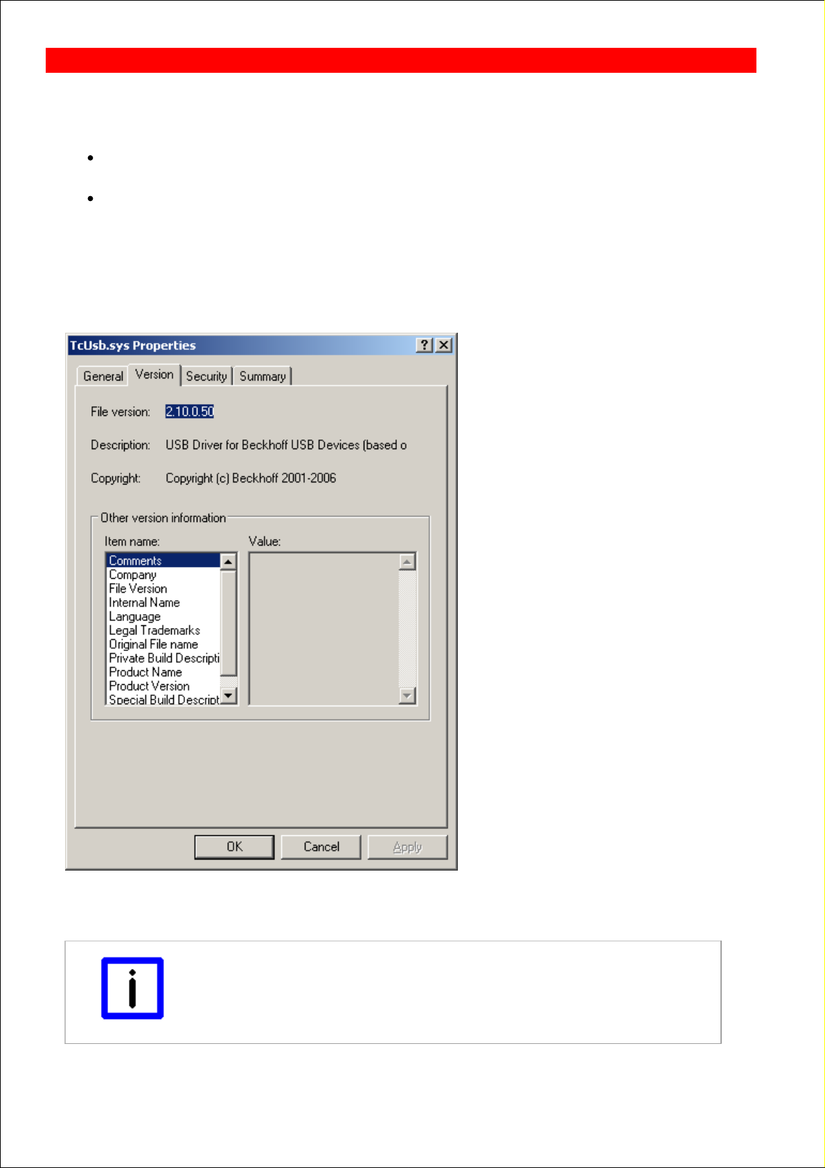
Update of TcUsb.sys
Depending on the installed version of TwinCAT and the installation order of CP-Link 3 and TwinCAT it might be
necessary to update the driver file TcUsb.sys.
If you install CP-Link 3 on a PC with an already installed TwinCAT, the version of the driver file TcUsb.sys will be
checked and, if necessary, replaced by a newer version. In this case an update is not necessary .
If you install TwinCAT on a PC with an already installed CP-Link 3, the installation process of TwinCAT might
replace the driver file TcUsb.sys by an older version. In this case you need to check the version and, if necessary,
update the file .
Version check
Open Windows Explorer and navigate to: C:\Windows\System32\drivers. If TwinCAT is installed this folder contains the
file TcUsb.sys. The version number can be checked via the file properties (right click -> Properties) on the tab Version :
If the version of TcUsb.sys is older than 2.10.0.54 it is necessary to update the file.
Perform update
Note
Version check of TcUsb.sys
Always check if TcUsb.sys needs to be updated (see above).
BECKHOFF CP-Link 3: Miscellaneous
Page 71
Page 72

Open Windows Explorer and navigate to: C:\Windows\System32\drivers. Rename the file TcUsb.sys, e.g. to
TcUsb_old.sys. The subfolder "Drivers" of the CP-Link 3 program directory contains the file TcUsb.sys. Copy this file to
C:\Windows\System32\Drivers.
Note
Restart the operating system
After the update of TcUsb.sys you need to restart the operating system!
Page 72
Page 73

CP-Link 3 LaunchApp
CP-Link 3 LaunchApp is a command-line application which enables the opportunity to start any application that way, that
the application window opens with a specific size on a specific monitor. You can get a details description for the usage of
CP-Link 3 LaunchApp when you start the program via command-line without any parameters. Therefor open a
command-line window and navigate to the subfolder Tools within the CP-Link 3 program directory, e.g. "C:\Program
Files\Beckhoff\CP-Link 3\Tools". Now type in "CPLink3LaunchApp.exe" into the command-line.
BECKHOFF CP-Link 3: Miscellaneous
Page 73
Page 74

Hints for cabling
In order to ensure a correct functioning of CP-Link 3, please note the following hints concerning the cabling for the CPLink 3 participants.
Note the hints listed in the Network Topology section.
Always run the network cables separated from power cables. Use (sufficiently) shielded network cables.
Ensure all CP-Link 3 participants to have the same zero potential in order to avoid potential equalisation via the
network cable.
BECKHOFF CP-Link 3: Miscellaneous
Page 74
Page 75

Comments
Known problems:
TwinCAT RT-Ethernet driver
If CP-Link 3 uses a network adapter which is configured as TwinCAT RT-Ethernet Adapter at the same time, this
may result in dropped connection on high network usage.
Please use TwinCAT 2.11, Build 1552 or newer, beginning with this version this issue is fixed.
Icons not visible
In certain cases icons of the host PC's desktop, or the pictograms for applications running on the host PC, are
only partially visible on the clients display, if at all. This phenomenon is only observed on multi-monitor host PCs.
In addition, only those clients that are displaying the screen content of the host PC's standard display device are
affected. This is a known issue in the Microsoft operating system Windows XP
(http://support.microsoft.com/kb/2501595 ).
Restrictions:
Remote desktop
It is not possible to use CP-Link 3 Configuration in a Remote Desktop session.
Realtime-Ethernet
If a network adapter of a CP-Link 3 client is used both for the CP-Link 3 connection as well as for real-time
Ethernet, it is not possible to transmit the “Virtual Graphics” data by UDP. If only one network adapter is available
for CP-Link 3 and real-time Ethernet, the “Virtual Graphics” data for the client must be transmitted by TCP (see
also the Client Configuration section).
Installation order of CP-Link 3 and TwinCAT
When installing CP-Link 3 or TwinCAT assure to install TwinCAT before CP-Link 3 (see also the Update of
TcUsb.sys section).
BECKHOFF CP-Link 3: Appendix
Page 75
Page 76

Troubleshooting
Fault
Possible cause
Solution
A client is not displaying the
image from the host PC, but
the image of the client's
operating system.
Faulty network connection.
Faulty configuration.
Check the network connection.
Make sure that the network
configuration of the host PC and the
client are correct.
Check the CP-Link 3 configuration
(see also the Client Configuration
section).
The host PC cannot connect to
a client even though the client
is reachable using the Ping
command.
Faulty firewall setting on the client.
For CE based clients: Wrong
directory used for installation.
Check the firewall settings of the
client (see also the Firewall
Configuration section).
For CE based clients: Always install
CP-Link 3 into the directory
suggested by the installation wizard
(see also the Installation - Client
section).
A client does not show any
image (black screen).
A network adapter in the client is
being used both for the CP-Link 3
connection and for real-time
Ethernet. It is not possible to
transmit the “Virtual Graphics” data
via UDP (see also the Comments
section).
Change the client's “Virtual
Graphics” data transfer protocol
over to TCP (see also the Client
Configuration section).
Exceptionally slow graphics
performance of a client.
The color depth of the client's
display does not match the
corresponding host display color
depth.
Adjust the color depth of the client's
display to match the color depth of
the corresponding host display (see
also the Installation - Client section).
The image displayed at a
client is faulty; some parts of
the screen are not updated, or
are updated only after a delay.
The network has a poor connection
quality, while the “Virtual Graphics”
data is being transmitted via UDP.
Change the client's “Virtual
Graphics” data transfer protocol
over to TCP (see also the Client
Configuration section).
Connection dropouts are
occurring; a client sometimes
shows the image from the host
PC, sometimes the image of
the client's operating system.
A network adapter of the host PC is
being used for the CP-Link 3
connection at the same time the
adapter is configured as a TwinCAT
RT Ethernet adapter (see also the
Comments section).
Please use TwinCAT 2.11, Build
1552 or newer, beginning with this
version this issue is fixed.
Alternative: The network adapter
may not be configured as TwinCAT
RT Ethernet Adapter. Install the
standard Intel® network card driver.
After touching the client touch
screen a dialog opens with
question "Minimize client
window?"
Virtual USB is not activated for this
client. The touch screen is used as
local device.
Activate virtual USB for this client. If
needed add HID devices to the USB
Device Blacklist in order to prevent
user inputs from this client. (see also
the Client Configuration section).
On using an Elo touch screen
via "Virtual USB" the mouse
moves, but does not follow the
finger. The touch screen
calibration fails.
Elo Touchscreen driver is not
installed on the host PC or the driver
is outdated.
Install a recent Elo Touchscreen
driver on the host PC. Run the Elo
alignment program on the host PC.
BECKHOFF CP-Link 3: Appendix
Page 76
Page 77

Setting the HID Focus
manually via ADS or using the
function block
FB_CPLink3_AcquireHidFocus
does not work.
The CP-Link 3 Service is not
running.
Verify the status of the CP-Link 3
Service. Maybe the CP-Link 3
Service needs to be registered or
started (see also CP-Link 3 Service
section).
On using an USB Bus Coupler,
the Coupler's outputs drop out
or the Bus Coupler does not
behave like expected.
Faulty configuration or faulty use of
the USB Bus Coupler.
Multiple Bus Couplers have identical
device numbers.
The cycle time for data exchange
with the Bus Coupler is too short.
Check the configuration for the use
of USB Bus Couplers (see also
Using the USB Bus Coupler ).
Ensure that different device
numbers are assigned to all Bus
Couplers (see also Device Number
of USB Bus Coupler ).
Use the recommended cycle time
for data exchange with the Bus
Coupler (see also Cycle time for
data exchange ).
The MissedCnt variable of an
USB Bus Coupler is
incrementing .
The cycle time for data exchange
with the Bus Coupler is too short.
Faulty configuration of the RT
Ethernet when accessing the Bus
Coupler via RT Ethernet.
Use the recommended cycle time
for data exchange with the Bus
Coupler (see also Cycle time for
data exchange ).
Check the RT Ethernet configuration
when accessing the Bus Coupler via
RT Ethernet (see also "Virtual USB
Interface (Remote)" via RT Ethernet
, or Access via network variables
(RT Ethernet) , or ADS access via
RT Ethernet )
A client's (running Windows
XP) USB devices cannot be
used if the PC has been
started in "Safe Mode".
The operating system prevents
loading particular CP-Link 3 drivers,
because these drivers use network
components of the operating system
that are not available in "Safe
Mode". The successful loading of
these drivers is a requirement for
the operating system to load the
USB-Hub driver. Therefore, the
USB-Hub driver is not loaded which
leads to the client's USB devices to
be unusable.
Start the operating system in "Safe
Mode with Networking".
Page 77
Page 78

Support and Service
Beckhoff and their partners around the world offer comprehensive support and service, making available fast and
competent assistance with all questions related to Beckhoff products and system solutions.
Beckhoff's branch offices and representatives
Please contact your Beckhoff branch office or representative for local support and service on Beckhoff products!
The addresses of Beckhoff's branch offices and representatives round the world can be found on her internet pages:
http://www.beckhoff.com
You will also find further documentation for Beckhoff components there.
Beckhoff Headquarters
Beckhoff Automation GmbH
Eiserstr. 5
33415 Verl
Germany
Phone:
+49(0)5246/963-0
Fax:
+49(0)5246/963-198
e-mail:
info@beckhoff.com
Beckhoff Support
Support offers you comprehensive technical assistance, helping you not only with the application of individual Beckhoff
products, but also with other, wide-ranging services:
support
design, programming and commissioning of complex automation systems
and extensive training program for Beckhoff system components
Hotline:
+49(0)5246/963-157
Fax:
+49(0)5246/963-9157
e-mail:
support@beckhoff.com
Beckhoff Service
The Beckhoff Service Center supports you in all matters of after-sales service:
on-site service
repair service
spare parts service
hotline service
Hotline:
+49(0)5246/963-460
Fax:
+49(0)5246/963-479
e-mail:
service@beckhoff.com
BECKHOFF Automation: Appendix
Page 78
 Loading...