

Page 1
www.basler.com
info@basler.com
INTRODUCTION
BE3 thermocouple temperature relays monitor remote
temperatures using thermocouple transducers. The relay
operates when the monitored temperature exceeds the
preset limit. The BE3-49TH provides overtemperatur e
protection and the BE3-49TL provides undertemper atur e
protection. Type J or K thermocouple inputs are available.
These inputs cover a wide range of temperatures.
SPECIFICATIONS
Operating Power
All units require externa l oper a ting pow er.
AC Operating Power
Nominal Voltage: 120 Vac, 240 Vac, or 480 Vac
Frequency: 45 to 65 Hz
Burden: 2 VA maximum
DC Operating Power
Nominal Voltage: 24 Vdc
Burden: <3 W
Thermocouple Input
The thermocouple input accommodates type J and type K
thermocouples and is thermocouple-break protected.
Type J
Minimum Range: 0 to 185°C (10 mV span)
Maximum Range: 0 to 870°C (50 mV span)
Type K
Minimum Range: 0 to 245°C (10 mV span)
Maximum Range: 0 to 1,230°C (50 mV span)
Cold Junction Compensation
Automatic over the range of 0 to 50°C
Overload
10 x continuous
Setpoint
Overtemperature Range: Adjustable 40 to 120% (±3%)
Undertemperature Range: Adjustable 0 to 80% (±3%)
Repeatability: Greater than 0.5% of full span
Time Delay: Adjustable from 0 to 10 s
Differential: Fixed at 2%
Output
Relay Type: D.P.D.T.
AC Rating: 250 V, 5 A, non-resistive,
DC Rating: 125 V, 1 A, resistive, 120 W
Mechanical Life: 5 million operations
Temperature
Operating Temperature: 0°C (32°F) to 60°C (140°F)
Functional Temperature: –25°C (–13°F) to 70°C (158°F)
Publication
9320600990
1200 VA
Revision
E
+1 618.654.2341 (USA)
Instructions
Model
Storage Temperature: –40°C (–40°F) to 70°C (158°F)
Temperature Coefficient: 0.03% per °C (300 ppm/°C)
Humidity
Relative Humidity: 95% non-condensing
Physical
Mounting: DIN rail 1.38” by 0.29” (35 mm by
Case: Complies with IEC 529, DIN
Case Material: Complies with UL 94VO
Weight: 0.88 lb (0.4 kg)
Size: 2.17” wide (55 mm)
Agency
cULus listed to UL 508 and CSA C22.2 No. 14
CE compliant
GOST-R certified per the relevant standards of Gosstandart
of Russia
BE3-49TH and BE3-49TL
7.5 mm)
40050, BS 5490
OPERATION
BE3 thermocouple temperature relays have two useradjustable controls: SET and DELAY. The SET control
adjusts the relay trip point. The BE3-49TL trips when the
monitored temperature decreases below the SET threshold.
The undertemperature SET level is adjustable from 0 to
80% (±3%) of the rated thermocouple temperature. The
BE3-49TH trips when the monitored temperature increases
above the SET threshold. The overtemperature SET level is
adjustable from 40 to 120% (±3%) of the rated thermocouple
temperature. The DELAY control adjusts the time from when
a fault is detected until the output contacts change state.
The DELAY control is adjustable from 0 to 10 seconds. All
BE3 thermocouple temperature relays have a green
POWER LED to indicate the condition of the power supply.
A red RELAY LED indicates the state of the output relay.
Setting Example
A BE3-49TH rated for a J type thermocouple with a
maximum temperature of 185°C has the following settings:
• SET - 80%
• DELAY - 5 s
An overtemperature condition is detected when the sensed
temperature increases to 148°C. The output trips 5 seconds
after the overtemperature condition is detected. If the
sensed temperature falls below 144.3°C (2% of nominal
fixed differential) before timeout, the relay resets.
INSTALLATION
BE3 thermocouple temperature relays are designed for
mounting on standard DIN rails that comply to DIN-EN
50022. Mounting involves hooking the top edge of the cutout
on the base of the case over one edge of the DIN rail. The
opposite side of the cutout containing the release clip is then
pushed over the opposite side of the DIN rail. To remove or
reposition the relay, lever the release clip and move the
relay as required. BE3 relays should be installed in a dry,
Date
03/14
Copyright
2014
Page 2
vibration-free location where the ambient temperature does
not exceed the operating temperature range. Connections to
the relay should be made using wire that meets applicable
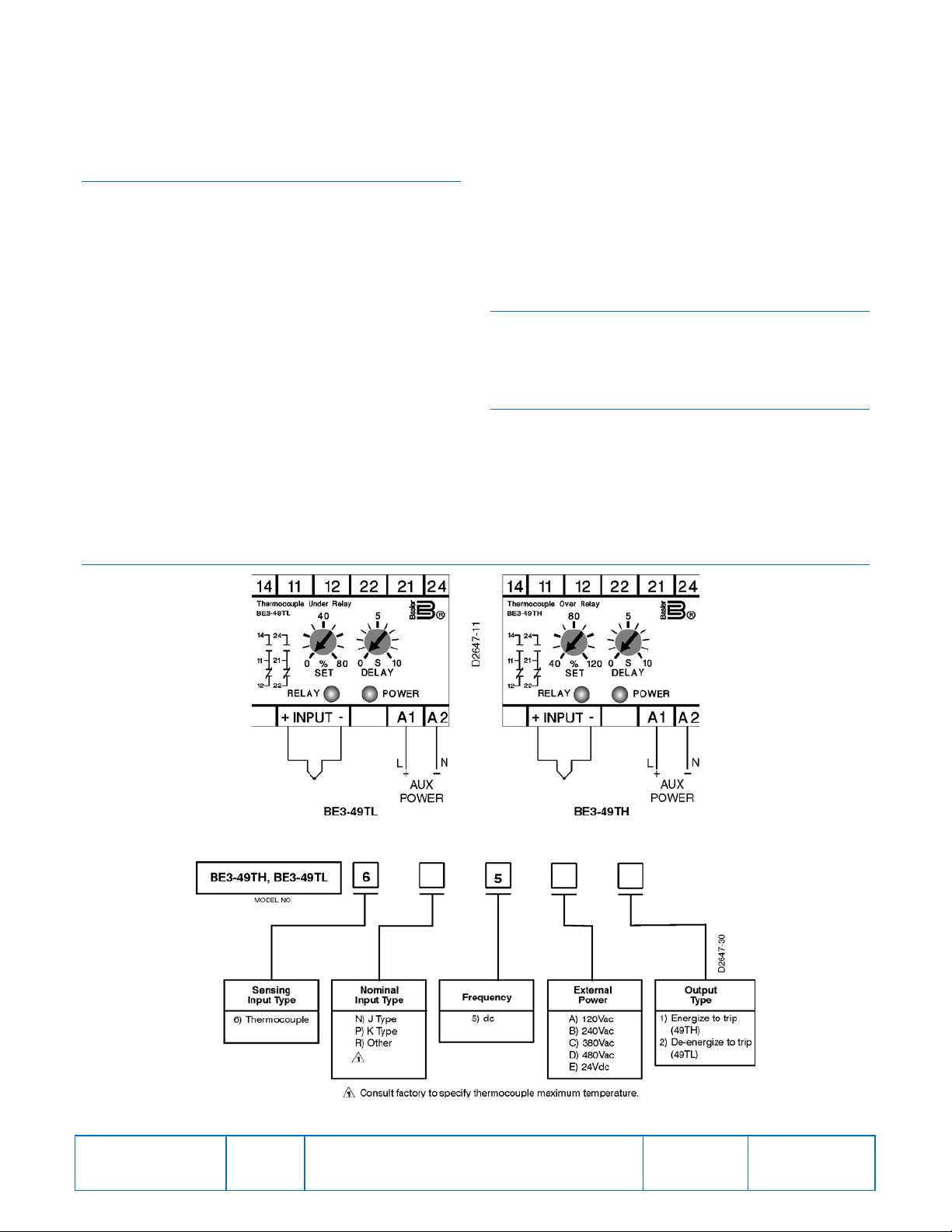
codes and is properly sized for the application. Figure 1
shows the terminal connections for the BE3-49TH and BE349TL relays.
CALIBRATION
The calibration marks on the faceplate have a maximum
error of 10% and are provided only as guides. Proper
calibration requires using a thermocouple table and a
millivoltmeter connected in parallel with a stable low-voltage
source. Use the following procedure to calibrate your relay.
Trip
1. Adjust the SET control fully clockwise (BE3-49TL) or
fully counterclockwise (BE3-49TH). Adjust the DELAY
control fully counterclockwise. Apply nominal external
operating power to the relay.
2. Apply a value of millivolts that corresponds to the
desired temperature trip level.
3. Slowly adjust the SET control until the relay trips.
Overtemperature Delay
1. Set the DELAY control at the desired time setting. Apply
nominal external operating power to the relay.
2. Apply a value of voltage that is just above the trip
setpoint. Measure the time from when the voltage is
applied until the relay trips.
FIGURES
3. Compare the measured time delay to the desired time
delay and adjust the DELAY control accordingly.
4. Repeat Steps 2 and 3 as required.
Undertemperature Delay
1. Set the DELAY control at the desired time setting. Apply
nominal external operating power to the relay.
2. Apply a value of voltage that is above the trip setpoint.
Remove the applied voltage and measure the time from
when the voltage is removed until the relay trips.
3. Compare the measured time delay to the desired time
delay and adjust the DELAY control accordingly.
4. Repeat Steps 2 and 3 as required.
MAINTENANCE
BE3 relays are solid-state devices that require no
maintenance. In the event that your relay requires repair,
contact Basler Electric, Highland, IL, USA for return
authorization.
ORDERING INFORMATION
Figure 2 shows the BE3 th erm ocou ple tem perature relay
style chart.
• BE3-49TH - Overtemperature
• BE3-49TL - Undertemperature
Publication
9320600990
Figure 1. BE3-49TL and BE3-49TH Thermocouple Temperature Relay Connections
Figure 2. BE3-49TH and BE3-49TL Style Number Identification Chart
Revision
E
Instructions
Date
03/14
Page
2 of 2
 Loading...