

Page 1
www.basler.com
+1 618.654.2341 (USA)
info@basler.com
INTRODUCTION
Six-input BE3 temperature relays use resistance
temperature detectors (RTDs) to monitor remote
temperatures. When any of six monitored temperatures
exceeds a preset limit, the corresponding LED indicator
lights, the TRIP LED lights, and the relay output operates.
BE3 temperature relays are available for use with 10 Ω
copper or 100 Ω platinum RTDs.
SPECIFICATIONS
Operating Power
All units require externa l oper a ting pow er.
Nominal Voltage: 120 Vac, ±25%, 45 to 65 Hz, 2 VA
240 Vac, ±25%, 45 to 65 Hz, 2 VA
24 Vdc, ±20%, galvanically
isolated, <3 W
RTD Inputs
The RTD inputs accommodate two- or three-wire RTDs.
Depending on the style number of the relay, the RTD inputs
accept either 10 Ω copper or 100 Ω platinum RTDs.
Style 5J5X1: 10 Ω copper RTDs
Style 5K5X1: 100 Ω platinum RTDs
The temperature measurement range of each input is 0 to
200°C.
Metering Output
Range: 0 to 1 mAdc
Burden: 5 kΩ maximum
Setpoints
Range: 50 to 100% (±3%) of input
temperature range
Repeatability: Greater than 0.5% of full span
Differential: Fixed at 2%
Outputs
Relay Type: S.P.D.T.
AC Rating: 250 V, 5 A, non-resistive,
1200 VA
DC Rating: 125 V, 1 A, resistive, 120 W
Mechanical Life: 5 million operations
Temperature
Operating Temperature: 0°C (32°F) to 60°C (140°F)
Functional Temperature: –25°C (–13°F) to 70°C (158°F)
Storage Temperature: –40°C (–40°F) to 85°C (185°F)
Temperature Coefficient: 0.03% per °C (300 ppm/°C )
Humidity
Relative Humidity: 95% non-condensing
Model
Physical
Mounting: DIN rail 1.38” by 0.29” (35 mm by
Case: Complies with IEC 529, DIN
Case Material: Complies with UL 94VO
Weight: 1.32 lb (0.59 kg)
Size: 3.94” wide (100 mm)
Agency
cULus listed to UL 508 and CSA C22.2 No. 14
CE compliant
GOST-R certified per the relevant standards of Gosstandart
of Russia
BE3-49R - 6 Inputs
7.5 mm)
40050, BS 5490
OPERATION
Six temperatures are monitored through RTDs connected to
the BE3 temperature relay. RTD connections are labeled A,
B, C, D, E, and F. One front-panel contr ol lab ele d SET is
used to adjust the trip level for all six RTDs. The setpoint is
adjustable from 50 to 100% (±3%) of the RTD temperature
range. When any RTD temperature exceeds the setpoint,
the TRIP LED lights, and the relay output energizes. Each
RTD has a corresponding LED to identify which RTD has
exceeded the temperature setpoint. For example, if the
temperature of RTDs B and C exceeds the trip level, the B,
C, and TRIP LEDs light and the relay output energizes. A
green LED labeled AUX indicates the power supply status.
INSTALLATION
BE3 temperature relays are designed for mount ing on
standard DIN rails that comply with DIN-EN 50022.
Mounting involves hooking the top edge of the cutout on the
base of the case over one edge of the DIN rail. The opposite
side of the cutout containing the release clip is then pushed
over the opposite side of the DIN rail. To remove or
reposition the relay, lever the release clip and move the
relay as required. BE3 relays should be installed in a dry,
vibration-free location where the ambient temperature does
not exceed the operating temperature range. Connections to
the relay should be made using wire that meets applicable
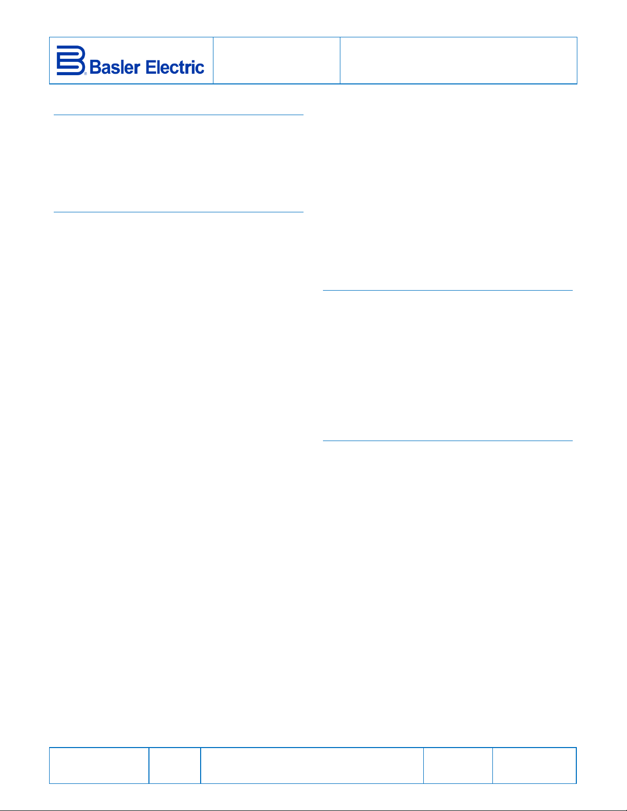
codes and is properly sized for the application. Figure 1
illustrates the terminal connections for the BE3-49R
temperature relay.
A burden resistor must be installed across all unused RTD
inputs that are not connected to an actual RTD. For units
with style number 5JXXX, it is suggested that a 10 Ω resistor
be connected across any unused RTD inputs. For units with
style number 5JXXX, it is suggested that a 100 Ω resistor be
connected across any unused RTD inputs. The minimum
power rating for the burden resistors is ¼ W.
Publication
9320500991
Revision
D
Instructions
Date
03/14
Copyright
2014
Page 2
CALIBRATION
Proper calibration requires a precision decade resistance
box with 1% accuracy or better. While calibrating the relay,
burden resistors must be connected across the remaining,
open RTD inputs. A temperature and resistance crossreference table for your RTDs is also needed. Use the
following procedure to calibrate your relay.
1. Adjust the SET control fully counterclockwise.
2. Connect the decade resistance box to RTD input A and
connect a 10 Ω (style 5JXXX) or 100 Ω (style 5KXXX)
burden resistor across the remaining RTD inputs. The
burden resistor power rating should be ¼ W or greater.
Apply nominal external operating power to the relay.
FIGURES
3. Set the decade resistance box at the value that
corresponds to the desired temperature setpoint.
4. Slowly adjust the SET control clockwise until the A and
TRIP LEDs light and the output relay energizes.
MAINTENANCE
BE3 relays are solid-state devices that require no
maintenance. In the event that your relay requires repair,
contact Basler Electric, Highland, IL, USA for return
authorization.
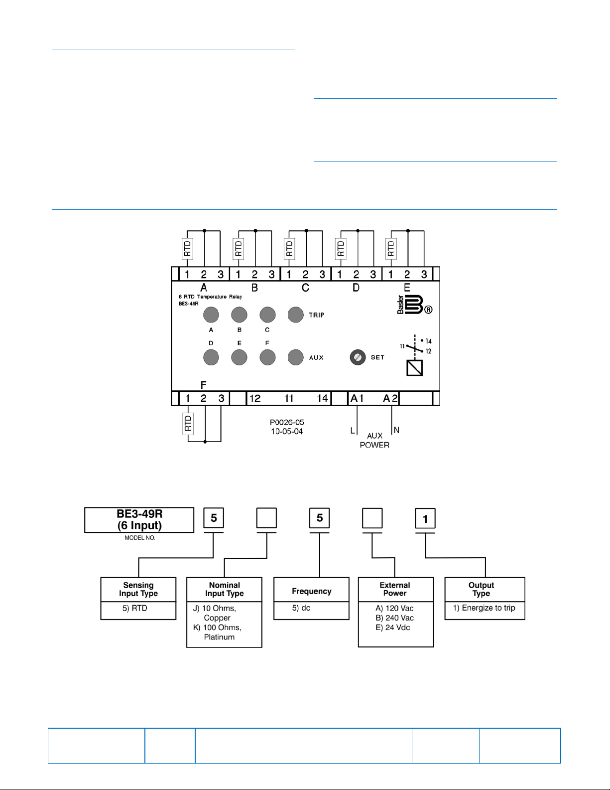
ORDERING INFORMATION
Figure 2 shows the BE3 temperature relay style chart.
Figure 1. BE3-49R - 6 Input Connections
Figure 2. BE3-49R - 6 Input Style Number Identification Chart
Publication
9320500991
Revision
D
Instructions
Date
03/14
Page
2 of 2
 Loading...