

Page 1
www.basler.com
info@basler.com
INTRODUCTION
BE3-47N phase balance relays protect three-phase lin es,
transformers, motors, and generators against phase
unbalance, phase loss, and phase reversal. BE3-47N/27
relays have the added feature of undervoltage protection.
The output relay energizes and the red RELAY LED lights
when a balanced input with the proper phase sequence is
sensed. The output relay de-energizes and the RELAY LED
goes out when a fault condition is detected. The green
POWER LED indicates the condition of the power supply.
Two external controls are provided: UNBAL (unbalance) and
DELAY. The UNBAL control adjusts the percentage of
unbalanced voltage at which the relay trips. The DELAY
control provides an adjustable time delay to prevent tripping
on voltage transients.
SPECIFICATIONS
Inputs
All units are self powered.
Nominal Voltage: 120 Vac, 240 Vac, 380 Vac, or
Overload Withstand: 1.25 times nominal continuously.
Frequency: 50, 60, or 400 Hz
Burden: <2 VA
Setpoint
Range: Adjustable 5 to 15% (±5%) of
Repeatability: Greater than 0.5% of full span
Undervoltage: Preset at 85% of nominal (BE3-
Time Delay: Adjustable 0 to 10 s
Operating Time: 200 ms, typical
Outputs
Relay Type: D.P.D.T.
AC Rating: 250 V, 5 A, non-resistive,
DC Rating: 125 V, 1 A, resistive, 120 W
Mechanical Life: 5 million operations
Temperature
Operating Temperature: 0°C (32°F) to 60°C (140°F)
Functional Temperature: –25°C (–13°F) to 70°C (158°F)
Storage Temperature: –40°C (–40°F) to 70°C (158°F)
Temperature Coefficient: 0.03% per °C (300 ppm/°C)
Humidity
Relative Humidity: 95% non-condensing
Publication
9320300990
+1 618.654.2341 (USA)
480 Vac
2 times nominal for 3 s.
nominal)
47N/27 only)
1200 VA
Revision
D
Instructions
Model
Physical
Mounting: DIN rail 1.38” by 0.29” (35 mm by
Case: Complies with IEC 529, DIN
Case Material: Complies with UL 94VO
Weight: 0.88 lb (0.4 kg)
Size: 2.17” wide (55 mm)
Agency
cULus listed to UL 508 and CSA C22.2 No. 14
CE compliant
GOST-R certified per the relevant standards of Gosstandart
of Russia
BE3-47N and BE3-47N/27
7.5 mm)
40050, BS 5490
OPERATION
The BE3-47N and BE3-47N/27 phase balance relays have
two external, user-adju sta ble c ontr ol s marked UNB AL and
DELAY. The UNBAL control adjusts the relay trip point. The
relay trips when the voltage becomes unbalanced by the
percentage set by the UNBAL control. The trip point is
adjustable from 5 to 15% (±5%) of nominal input. The
DELAY control adjusts the time from when a fault is
detected until the output contacts change state. The delay is
adjustable from 0 to 10 seconds. The undervoltage feature
of the BE3-47N/27 has no external adjustment and is fixed
at 85% of the nominal input voltage. If all three phases
remain balanced, but decrease below 85% of nominal
voltage, the relay de-energizes.
Settings Example
A BE3-47N/27 relay with a nominal input rating of 120 Vac
has the following settings:
• UNBAL - 10%
• DELAY - 5 s
The relay detects a phase unbalance when any one phase
decreases to 108 Vac or increases to 132 Vac. The output
relay trips five seconds after the phase unbalance is
detected. The output relay also trips if all phases decrease
to 85% of nominal, or 102 Vac.
INSTALLATION
BE3 phase balance relays are designed for mounting on
standard DIN rails that comply to DIN-EN 50022. Mounting
involves hooking the top edge of the cutout on the base of
the case over one edge of the DIN rail. The opposite side of
the cutout containing the release clip is then pushed over
the opposite side of the DIN rail. To remove or reposition the
relay, lever the release clip and move the relay as required.
BE3 relays should be installed in a dry, vibration-free
location where the ambient temperature does not exceed
the operating temperature range. Connections to the relay
should be made using wire that meets applicable codes and
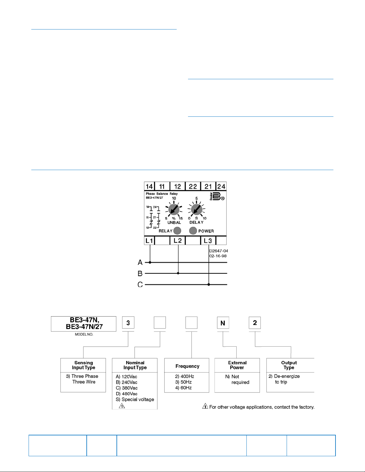
is properly sized for the application. Figure 1 shows the
terminal connections for the BE3-47N/27 relay. Connections
for the BE3-47N relay are identical.
Date
04/14
Copyright
2014
Page 2
CALIBRATION
The calibration marks on the faceplate have a maximum
error of 10% and are provided only as guides. Proper
calibration requires using an accurate voltmeter in parallel
with the input signal. Use the following procedure to
calibrate your relay.
Unbalance
1. Adjust the UNBAL control fully clockwise and the
DELAY control fully counterclockwise.
2. Apply three-phase, nominal input voltage with the
proper phase sequence to the relay. The output relay
should energize.
3. Lower one phase of the applied voltage to the desired
trip level. Slowly adjust the UNBAL control
counter c lockwise until the relay trips.
Delay
1. Set the DELAY control at the desired time setting.
2. Apply three-phase, nominal input voltage with the
proper phase sequence to the relay.
FIGURES
3. Step down one phase of the applied voltage below the
relay trip point. Using an appropriate timing device,
measure the time from when the voltage is reduced
until the relay trips.
4. Compare the measured time to the desired time delay
and adjust the DELAY control accordingly.
5. Repeat Steps 3 and 4 as required.
MAINTENANCE
BE3 relays are solid-state devices that requ ire no
maintenance. In the event that your relay requires repair,
contact Basler Electric, Highland, IL, USA for return
authorization.
ORDERING INFORMATION
Figure 2 shows the BE3 phase balance rel ay style chart.
• BE3-47N - Phase Balance
• BE3-47N/27 - Phase Balance/Undervoltage
Publication
9320300990
Figure 1. BE3-47N, BE3-47N/27 Phase Balance Relay Connections
Figure 2. BE3-47N, BE3-47N/27 Style Number Identification Chart
Revision
D
Instructions
Date
06/14
Page
2 of 2
 Loading...