


FH085D36D
Bard FH085D36D, FH110D48D, FH110D60D, FLF085D36D, FLR085D36D Installation Instructions Manual
...
OIL FURNACE
INSTALLATION INSTRUCTIONS
MODELS
FH085D36D FH110D48D FH110D60D
FLF085D36D FLR085D36D FLF110D48D
FLR110D48D FLR140D60D FC085D36D
WARNING
READ ALL INSTRUCTIONS CAREFULL Y BEFORE BEGINNING THE
INSTALLATION.
THIS INST ALLATION MUST COMPLY WITH THESE INSTRUCTIONS AND
THE REQUIREMENTS OF ALL GOVERNING CODES AND ORDINANCES FOR
THE INST ALLATION LOCATION.
IT IS THE RESPONSIBILITY OF INSTALLER TO KNOW AND UNDERSTAND
ALL OF THESE REQUIREMENTS.
F AILURE TO DO SO COULD CREATE A HAZARD RESULTING IN PROPER TY
DAMAGE, BODIL Y INJURY OR DEATH.
FOR YOUR SAFETY
DO NOT STORE OR USE GASOLINE OR OTHER FLAMMABLE V APORS OR
LIQUIDS IN THE VICINITY OF THIS OR ANY OTHER APPLIANCE.
IMPORTANT NOTICE
THIS FURNACE IS NOT INTENDED FOR USE AS A CONSTRUCTION
HEA TER. USE OF THIS FURNACE DURING CONSTRUCTION AND FINISHING
PHASES OF A STRUCTURE IS CONSIDERED AS "OPERA TION IN A
CORROSIVE A TMOSPHERE" AND "UNUSUAL, NEGLIGENT OR IMPROPER
USE" AND AS SUCH ARE CONSIDERED EXCLUSIONS BY THE BARD
MANUFACTURING COMPANY LIMITED W ARRANTY.
Bard Manufacturing Company
Bryan, Ohio 43506
Since 1914...Moving ahead just as planned.
Manual: 2100-392A
Supersedes:
File: VOL. I, TAB 3
Date: 12-17-01
Copyright 2001

CONTENTS
Getting Other Information and Publications
Installation and Operating Instructions
Equpment Selection ...............................................2
Locating the Furnace..............................................2
Duct Work...............................................................6
Installing a Cooling Unit..........................................6
Wiring ...............................................................6
Oil Line Piping ........................................................8
Beckett AFG Oil Burner..........................................8
Beckett “CleanCut” Oil Pump .................................9
Beckett Solid State Igniter ......................................9
Beckett R7184B Primary Control............................9
Beckett R7184B Primary Operational Guide ........10
Burner Set up and Adjustments ........................... 11
Burner Nozzle and Electrode Adjustments...........14
Ventilation and Combustion Air ............................14
Louvers and Grilles...............................................18
Venting .............................................................18
Thermostat ...........................................................18
Fan & Limit Control...............................................18
T ABLES
Table 1 Minimum Clearances ............................. 2
Table 2 Dimensions Lo-Boy Models .................. 3
T able 3 Dimensions Hi-Boy Models .................... 4
T able 4 Dimensions Counterflow Models............ 5
Table 5 Electrical Data ........................................ 7
Table 6 Furnace Data ........................................11
Table 7 Correlation of % of CO
Reserve Air .......................................... 13
Table 8 No. 2 Fuel Oil Efficiency Chart ............. 13
T able 9 Recommended Start-Up Settings ........ 13
T able 10 Round Duct Sizing ............................... 14
Table 1 1 Sq.Ft. Required as
Unconfined Space................................ 15
Table 12 Minimum Ventilation Openings............. 16
Table 13 Temperature Rise Ranges, Limit
Control Settings, and
Heating Blower Speeds........................ 19
Table 14 Filter Sizes for Gas Furnaces............... 20
, O2 and
2
Filters
Hi-Boy Models – Filter Locations & Removal
and Replacement Procedures ..............................20
Counterflow Models – Filter Locations ...............21
Lo-Boy Models – Filter Locations .......................22
Maintenance
Lubrication ............................................................23
Inspect Air Filter....................................................23
Final Inspeciton and Test......................................23
Service Hints ........................................................23
Combination Combustion Chamber/Burner
Mounting System..................................................24
To Remove Burner Only .......................................24
To Remove Entire Combustion Chamber
Mounting System..................................................24
Common Causes of Trouble.................................26
Care of Finish .......................................................26
Cleaning of Furnace .............................................26
Blower System Resistance Curves ................ 27-30
Wiring Diagrams............................................. 31-33
FIGURES
Figure 1 Lo-Boy Models Dimensions ............... 3
Figure 2 Hi-Boy Models Dimensions................ 4
Figure 3 Counterflow Models Dimensions ....... 5
Figure 4 Typical Installation Requirement
Front Flue .......................................... 7
Figure 5 T ypical Single Inside
Tank Installation................................. 8
Figure 6 Pressure Gauge Connection to
Pressure Gauge Port....................... 12
Figure 7 Electrode Adjustments..................... 14
Figure 8 All Air From Inside Building.............. 15
Figure 9 All Air From Outdoors ...................... 16
Figure 10 All Air From Outdoors Through
Ventilated Attic................................. 17
Figure 11 All Air From Outdoors - Inlet Air
From Ventilated Crawl Space and
Outlet Air to Ventilated Attic............. 17
Figure 12 Typical Installation of 16x25x1
Filter Rack........................................ 20
Figure 13 Typical Installation of 20x25x1
Filter Rack........................................ 20
Figure 14 Filter Installation - Counterflow
Models ............................................. 21
Figure 15 Filter Installation - Lo-Boy Models ... 24
Figure 16A Removal of Burner Only .................. 20
Figure 16B Removal of Entire Combustion
Chamber Mounting System ............. 25
i

GETTING OTHER INFORMA TION and PUBLICATIONS
These publications can help you install the furnace. You
can usually find these at your local library or purchase
them directly from the publisher. Be sure to consult
current edition of each standard.
National Fuel Gas Code ........... ANSI Z223.1/NFPA54
National Electrical Code ......................ANSI/NFPA 70
Standard for the Installation .............. ANSI/NFPA 90A
of Air Conditioning and Ventilating Systems
Standard for Warm Air...................... ANSI/NFPA 90B
Heating and Air Conditioning Systems
Standard for Chimneys, Fireplaces, Vents ... NFPA 211
and Solid Fuel Burning Appliances
Load Calculation for .......................... ACCA Manual J
Residential Winter and Summer Air Conditioning
FOR MORE INFORMATION, CONTACT
THESE PUBLISHERS:
ACC A Air Conditioning Contractors of America
1712 New Hampshire Ave. N.W.
Washington, DC 20009
Telephone: (202) 483-9370
Fax: (202) 234-4721
ANSI American National Standards Institute
11 West Street, 13th Floor
New York, NY 10036
Telephone: (212) 642-4900
Fax: (212) 302-1286
ASHRAE American Society of Heating Refrigerating,
and Air Conditioning Engineers, Inc.
1791 Tullie Circle, N.E.
Atlanta, GA 30329-2305
Telephone: (404) 636-8400
Fax: (404) 321-5478
Duct Design for Residential .............. ACCA Manual D
Winter and Summer Air Conditioning
and Equipment Selection
NFPA National Fire Protection Association
Batterymarch Park
P.O. Box 9101
Quincy, MA 02269-9901
Telephone: (800) 344-3555
Fax: (617) 984-7057
Manual 2100-392
Page 1
INST ALLATION and OPERATING INSTRUCTIONS
EQUIPMENT SELECTION
An accurate heating load calculation must be conducted
using American Society of Heating, Refrigeration and
Air Conditioning Engineers (ASHRAE) or Air
Conditioning Contractors of America (ACCA) manuals.
Do not add a large safety factor above the calculated
value. If the calculated heating load requirement
exceeds the heating capacity rating of a given model,
use only the next larger size available. Never increase
by any more than absolutely necessary based upon
available equipment heating capacities. Always select
based upon heat capacity (output), never use input
capacities.
NOTE: It is the personal responsibility and
obligation of the purchaser to contract a
qualified installer to assure that installation
is adequate and is in conformance with
governing codes and ordinances.
LOCATING THE FURNACE
When installing the furnace be sure to provide adequate
space for easy service and maintenance. Locate the
furnace as close to the chimney as practical, giving
consideration to the accessibility of the oil burner,
controls, and blower for service. Allow a minimum of
24 inches at front of furnace for servicing oil burner.
Allow adequate room for filter and blower
maintenance. Clearance from combustible material as
stated on the furnace and repeated in Table 1 must be
maintained. For damp basement installations, a raised
concrete pad is recommended. This will help keep the
bottom of the furnace dry and reduce rusting.
An oil burner must have a generous supply of
combustion air to operate properly. The flow of
combustion and ventilating air must not be obstructed
from reaching the furnace. See “Ventilation and
Combustion Air” section.
The furnace area must be kept clear and free of
combustible materials, gasoline and other flammable
vapors and liquids.
This unit is not designed for mobile home or trailer
installations. Always install furnace in a level position.
TABLE 1
MINIMUM CLEARANCES
sehcnI--secnaraelCnoitallatsnImuminiM
1
ledoM
D63D580HF
D84D011HF
D06D011HF
D84D011FLF
D84D011RLF
D63D580CF
j
C
NC
*
**
4
4
4
D63D580FLF
6
D63D580RLF
6
6
6
D06D041RLF
6
6
For the first three (3) feet from plenum. After three (3) feet, no clearance required.
Combustible flooring
Noncombustible floor
Maintained on one side or the other to achieve filter access and/or blower service.
Floor must be noncombustible. For furnace only installation can be installed on combustible
flooring only when installed on special base part no. CFB7 available from factory. When air
conditioning coil cabinet DCB23-22 is used then use special base part no. CFB23.
1
1
1
0
81
0
81
81
1
2
2
2
2
2
2
2
2
2
2
2
2
2
2
2
2
2
2
2
2
2
2
2
2
2
2
2
tcuD
2
2
2
2
2
2
2
2
2
eulF
epiProolFtnorFkcaBsediSpoTsediStnorFkcaBsediS
9
9
9
9
9
9
9
9
9
C
C
C
CN
CN
CN
CN
CN
**
CN
ecivreSmuminiM
secnaraelCecanruFmunelP
42
42
42
42
42
42
42
42
42
---
---
---
42
42
42
42
42
---
---
---
---
*
81
81
*
81
*
81
*
81
*
---
Manual 2100-392
Page 2

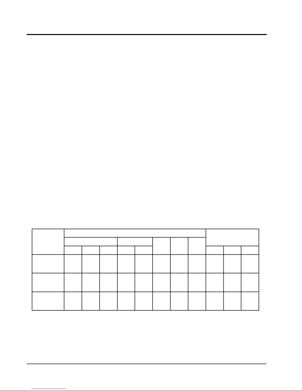
TABLE 2
LO-BOY MODELS
DIMENSIONS (INCHES)
munelP
tenibaC
ledoM
rebmuN
D63D580FLF
D63D580RLF
D84D011RLF
D84D011RLF
D06D041RLF62050502x5261x52raeR68/5-34---1x52x021
j
Washable type filter 1” nom. thickness
A
32
32
32
32
B
htdiW
C
htpeD
4/1-74
4/1-74
4/1-74
4/1-74
thgieH
4/1-04
4/1-04
4/1-44
4/1-44
ExD
sgninepOnoitcennoCeulFsretliFriA
FxD
ylppuS
02x22
02x22
02x22
02x22
nruteRnoitacoL
61x22
61x22
61x22
61x22
G
tnorF
raeR
tnorF
raeR
HJ
.aiD
6
6
6
6
eziS
---
43
---
83
4/1-5
--4/1-5
---
1
.oN
desU
1x02x61
1
1x02x61
1
1x02x02
1
1x02x02
1
FIGURE 1
LO-BOY MODELS DIMENSIONS
MIS-1345
Manual 2100-392
Page 3
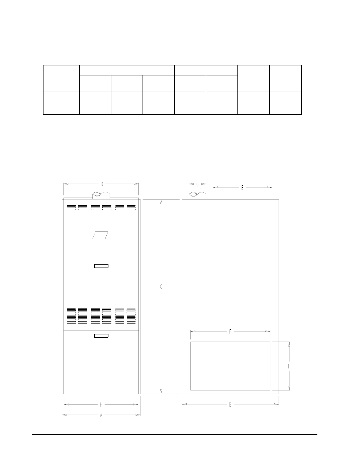
TABLE 3
HI-BOY MODELS
DIMENSION (INCHES)
tenibaCsgninepOmunelP
ledoM
rebmuN
D63D580HF
D84D011HF
D06D011HF
A
htdiW
32
32
32
j
Washable type filter
k
Left or right side return air option. Must be cut in by installer.
B
htpeD
2/1-13
2/1-13
2/1-13
C
thgieH
65
06
06
ExD
ylppuS
02x22
02x22
02x22
2
HxF
nruteR
41x32
41x32
41x32
G
.aiDeulF
6
6
6
1
eziSretliF
52x61
52x61
52x02
FIGURE 2
HI-BOY MODELS DIMENSIONS
Manual 2100-392
Page 4
MIS-1346
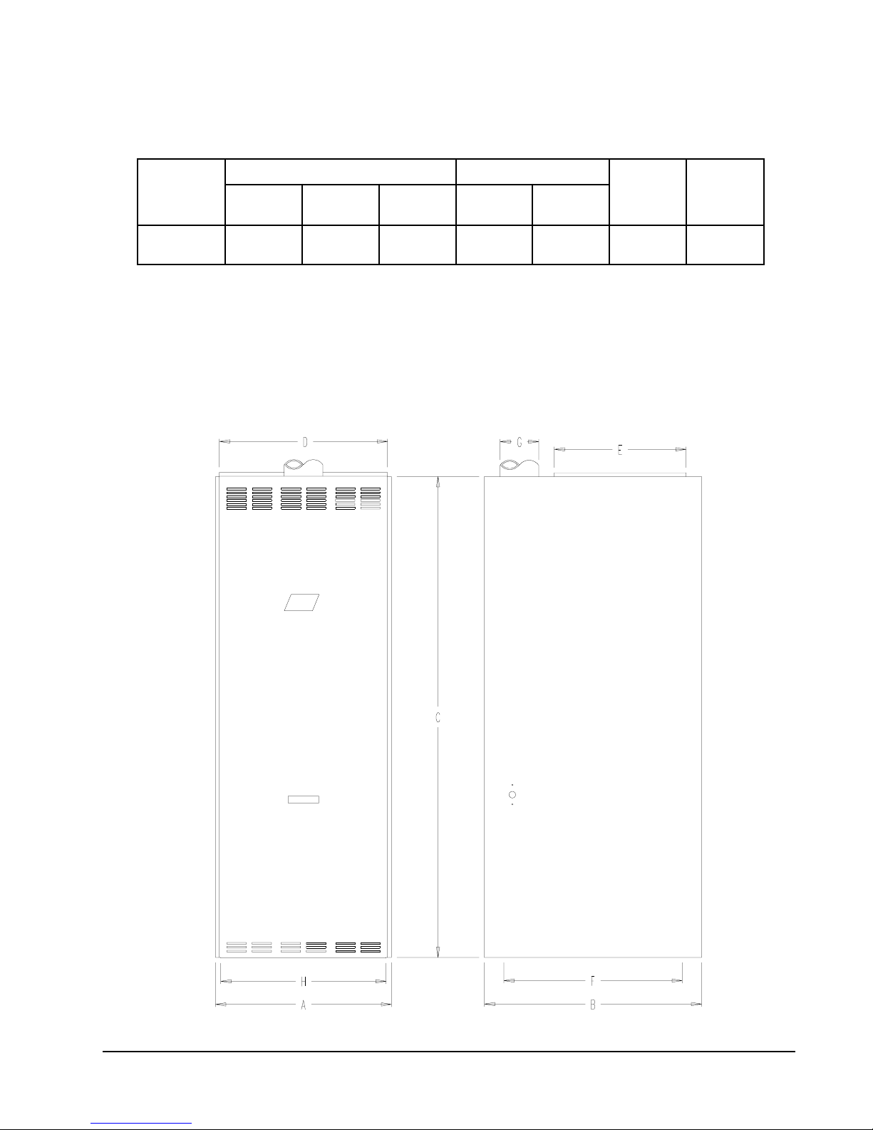
TABLE 4
COUNTERFLOW MODELS
DIMENSION (INCHES)
tenibaCsgninepOmunelP
ledoM
rebmuN
D63D580CF322/1-926502x2291x816
A
htdiW
j
Washable type filter
k
Left or right side return air option. Must be cut in by installer.
B
htpeD
C
thgieH
ExD
2
nruteR
HxF
ylppuS
G
.aiDeulF
FIGURE 3
COUNTERFLOW MODELS DIMENSIONS
1
eziSretliF
02x01
02x51
MIS-1344
Manual 2100-392
Page 5

DUCT WORK
The air distribution system should be designed and
installed in conformance with manuals published by Air
Conditioning Contractors of America (ACCA) as set
forth in Manual D, or ASHRAE publications.
IMPORTANT
When a furnace is installed so that supply
ducts carry air circulated by the furnace to
areas outside the space containing the
furnace, the return air must also be handled
by a duct(s) sealed to the furnace casing and
terminating outside the space containing the
furnace This is to prevent drawing possible
hazardous combustion products into the
circulated air.
INSTALLING A COOLING UNIT
When the furnace is used in connection with a cooling
unit*, the furnace shall be installed parallel with or on
the upstream side of the cooling unit to avoid
condensation in the heating element. With a parallel
flow arrangement, the dampers or other means used to
control flow of air shall be adequate to prevent chilled
air from entering the furnace, and if manually operated,
must be equipped with means to prevent operation of
either unit, unless the damper is in the full heat or cool
position.
* A cooling unit is an air conditioning coil, heat
pump coil or chilled water coil.
When installing a cooling unit above an FH or FL
(below on an FC) series furnace, the coil must be
spaced far enough from the furnace outlet to assure
proper operation of the furnace. Bard supplied coils,
when used with Bard supplied coil cabinets, are
automatically positioned.
For top discharge FH and FL models, when coils are
installed without using Bard coil cabinets or coils of
another brand are used, the coil drain pan should be
located a minimum of two (2) inches above the top of
the furnace cabinet. If a greater clearance is specified
by the coil manufacturer then it would apply.
INADEQUATE SUPPLY AIR and/or RETURN
AIR DUCT SYSTEMS
Short cycling because of limit control operation can be
created by incorrectly designed or installed supply and/
or return air duct systems.
The duct systems must be designed using ASHRAE or
ACCA design manuals and the equipment CFM and
external static pressure ratings to insure proper air
delivery capabilities.
On replacement installations, particularly if equipment
is oversized, the duct systems can easily be undersized.
Modifications may be required to assure that the
equipment is operating within the approved
temperature rise range when under full rated input
conditions, and that no short cycling on limit controls is
occurring.
INSTALLING THE FURNACE
A typical installation is shown in Figure 4. All parts of
the furnace installation (furnace, oil tank and piping
systems, combustion and ventilation air, venting, etc.)
must comply with NFPA31, Installation of Oil Burning
Equipment -- latest edition. This drawing shows the
typical connecting parts needed to correctly install this
furnace. Make sure that all parts of the heating system
comply with the local codes.
Check the furnace and your load calculation to verify
that the unit is properly sized. (Refer to Equipment
Selection” section on Page 2.)
The correct size of unit needed may be substantially
smaller than the unit being replaced due to home
improvements and technology advancements since the
initial installation.
WIRING
FACTORY WIRING
All units are fully factory wired. Multispeed blowers
are factory wired on high speed for cooling/manual fan
operation. Heating speeds are wired for the largest
input and may need lower speed for field installed low
input nozzle. If replacement wire is necessary, use 105
degrees C minimum. See electrical data, Table 5.
NOTE: If drain pan is anything other than a steel pan
particular attention must be given to the
installation instructions for the coil to make
sure it is acceptable for use with these oil
furnaces having maximum outlet air
temperature of 200° F.
See CFM versus static pressure tables on pages 23-26
for additional information.
Manual 2100-392
Page 6
FIELD WIRING
All wiring must conform to the National Electrical
Code and all local codes. A separate fuse or breaker
should be used for the furnace.
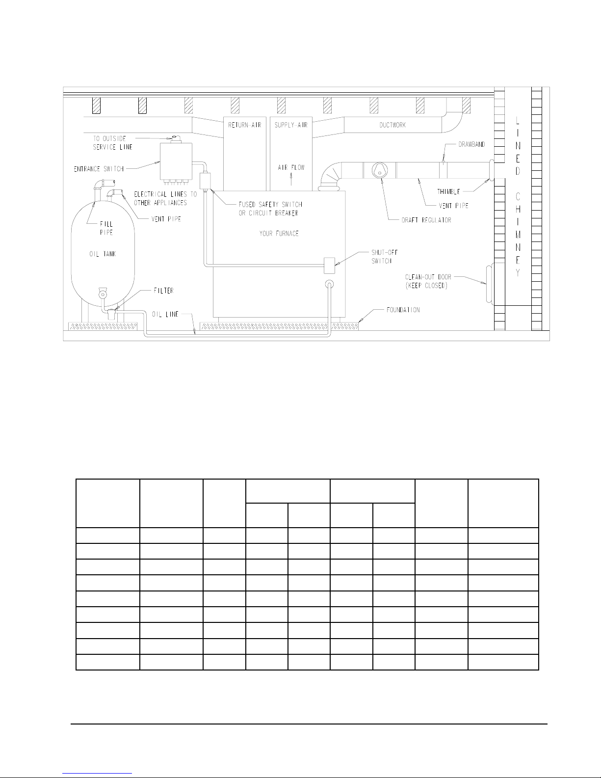
FIGURE 4
TYPICAL INSTALLATION REQUIREMENTS
FRONT FLUE LO-BOY MODEL SHOWN
NOTE: The chimney must be lined with a high temperature noncorrosive material that complies with the local
codes, or in their absence with Standard for Chimneys and Vents, NFPA211. Also see section on Venting
in these instructions.
TABLE 5
ELECTRICAL DATA
rotoMrewolBrotoMrenruB
latoT
ledoMHP-ZH-stloV
spmA
D63D580HF1-06-5112.93/15.77/17.15151
D84D011HF1-06-5112.212/15.017/17.16102
D06D011HF1-06-5112.414/35.217/17.19102
D63D580FLF1-06-5113.713/16.57/17.15151
D63D580RLF1-06-5113.713/16.57/17.15151
D84D011FLF1-06-5112.212/15.017/17.16102
D84D011RLF1-06-5112.212/15.017/17.16102
D06D041RLF1-06-5112.414/35.217/17.19102
D63D580CF1-06-5113.73/16.57/17.15151
PHALFPHALF
MIS-1335
emiT.xaM
muminiM
tiucriC
yticapmA
esuFyaleD
RCAHro
rekaerBtiucriC
Manual 2100-392
Page 7
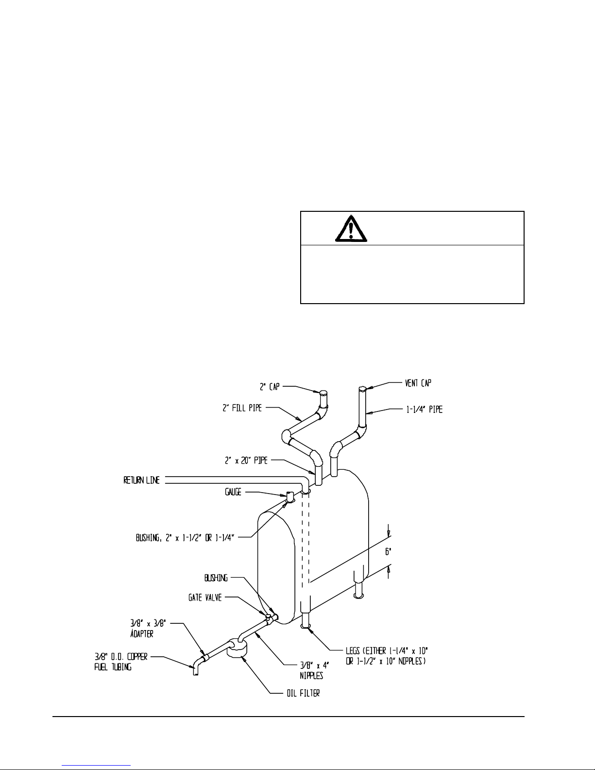
OIL LINE PIPING
First determine whether the pipe system is to be a single
line system or a two line system. All connections must
be absolutely air tight or you will have a malfunction of
the burner. When installing the piping, a good oil filter
should be installed close to the burner. A single line
system is recommended for gravity feed.
A typical single inside tank installations shown in
Figure 5. For installation details for this and other tank
configurations, refer to NFPA31 -- latest edition. All
tank and pipe setups must comply with NFPA31.
BECKETT AFG OIL BURNER
This furnace is equipped with a high static Beckett AFG
oil burner which is designed to produce adequate draft
in nearly any vertically vented application. The burner
employs the latest time tested controls of the highest
quality. The controls consist of a high voltage Beckett
solid state igniter, a Beckett “CleanCut” oil pump with
an integral solenoid valve, and a Beckett R7184B
primary control.
These controls were selected for their proven high
quality, dependability, and serviceability. With proper
maintenance this burner assembly will provide many
years of reliable service.
All units are shipped with the oil burner installed, and
with high rate oil nozzle installed designed for use with
No. 1 or No. 2 fuel oil. Inspect firepot refractory
before firing to be sure it has not been jarred out of
position in shipment. Burner air tube must not
extend beyond inside surface of firepot. Burner
head should be centered on the combustion chamber
opening. See Figures 16A and 16B.
WARNING
Never attempt to use gasoline in your furnace.
Gasoline is more combustible than fuel oil and
could result in a serious explosion causing
damage, injury or death.
FIGURE 5
TYPICAL SINGLE INSIDE TANK INSTALLATION
Manual 2100-392
Page 8
MIS-1340

The following is a detailed explanation of each control
included in the Becket AFG Oil Burner, how each
operates, how to set up the burner, and how to
troubleshoot problems should they occur.
BECKETT “CLEANCUT” OIL PUMP
This oil pump is equipped with an oil solenoid valve
installed in the pump housing. This feature provides
quick cutoffs resulting in reduction in smoke after the
burner shuts down. This is a time proven pump design
and is capable of both one and two pipe systems. This
pump requires a pre-purge style primary control such as
the R7184B primary. All installation and set up
instructions are outlined in the “Oil Pump
Specification” section of the installation instructions
manual.
As an improved service feature Bard Manufacturing has
installed a brass tee fitting next to the oil line output of
the pump for installing a pressure gauge to ensure the
correct pump pressure. Refer to the “Burner Set Up and
Adjustment” section in the manual.
BECKETT SOLID STATE IGNITER
This igniter differs from the traditional iron core
transformer in that it produces a 14,000 volt spark
instead of a 10,000 volt spark of the iron core
transformer. This hotter spark provides for cleaner,
faster ignitions. Being solid state technology this
igniter is less susceptible to problems caused by voltage
variations. It also has a greater ability to ignite cold
and/or inconsistent oil. The solid state igniter is wired
to the primary control the same as a standard iron core
transformer.
BECKETT R7184B PRIMARY CONTROL
The R7184B Interrupted Electronic Oil Primary is a
line voltage, safety rated, interrupted ignition oil
primary control for residential oil burners. The R7184B
used with a cad cell flame sensor, operates the oil
burner and oil valve. The primary controls fuel oil,
senses flame, controls ignition spark and is designed to
notify a remote alarm circuit before going into lockout
when equipped with a flame monitoring system.
This primary control, though it possesses the latest
technology, is a very simple control to operate and
provides additional troubleshooting features to ease
service and reduce down time. Once the features and
operation of this control are understood the service
person will find it a welcomed addition. In an effort to
help in the transition to the R7184B primary control the
operational guide is provided following on Page 10.
Manual 2100-392
Page 9
 Loading...