

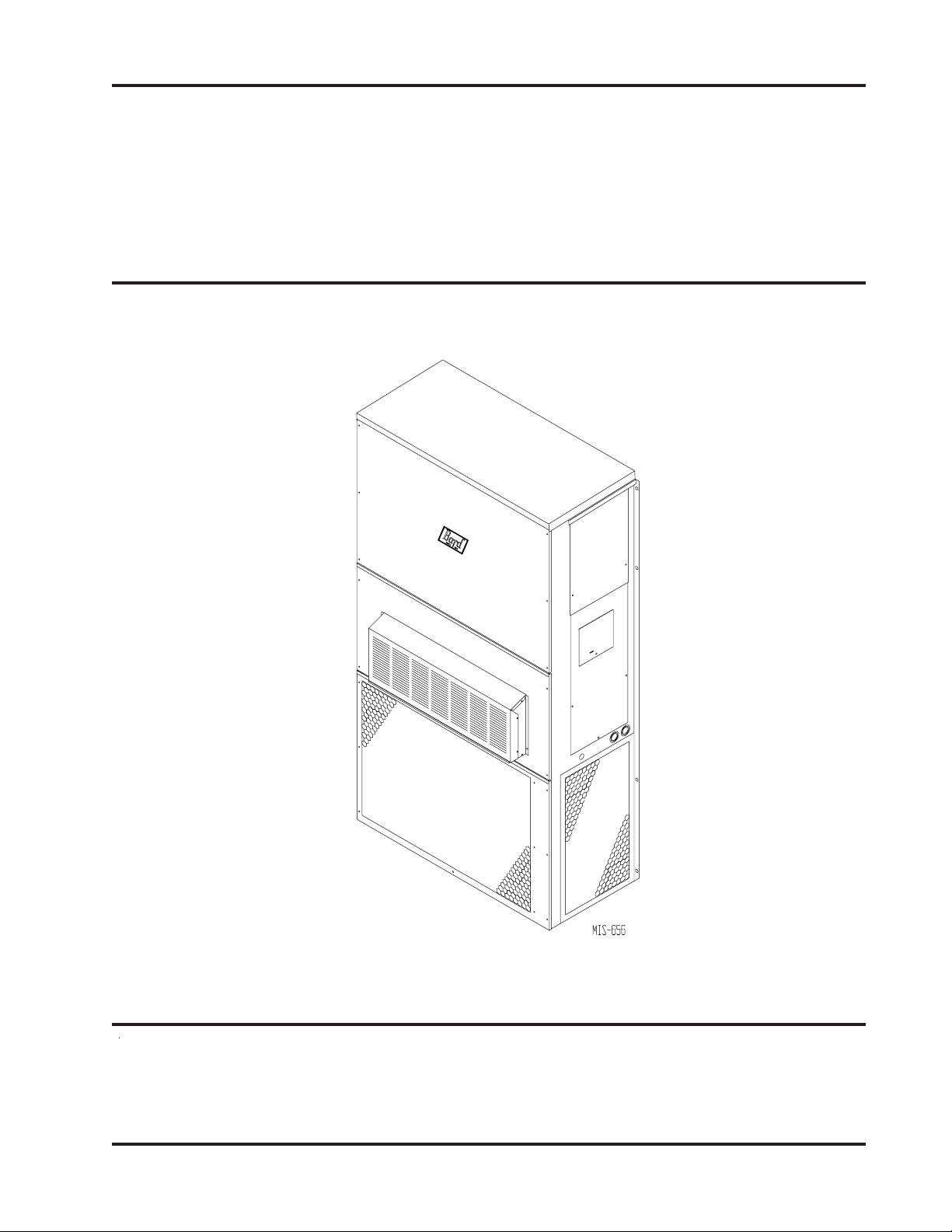
WALL MOUNTED
INSTALLATION
INSTRUCTIONS
PACKAGED HEAT PUMP
Models:
WH301, WH361
© Copyright 2003
Bard Manufacturing Company, Inc.
Bryan, Ohio 43506
Since 1914. . .Moving ahead just as planned.
Manual No.: 2100-193O
Supersedes: 2100-193N
File: Volume III, Tab 17
Date: 05-04-07
Manual 2100-193O
Page 1 of 26

CONTENTS
G
etting Other Information and Publications
For more information,
contact these publishers ........................................3
Wall Mount General Information
Heat Pump Wall Mount Model Nomenclature ........ 4
Shipping Damage .................................................. 4
General ............................................................. 4
Duct Work ...................................................... 4 & 8
Filters ............................................................. 8
Fresh Air Intake ...................................................... 8
Condensate Drain .................................................. 8
Installation Instructions
Wall Mounting Information ..................................... 9
Mounting the Unit................................................... 9
Top Outlet Only ...................................................... 9
Wiring — Main Power .......................................... 15
Wiring — Low Voltage Wiring............................... 15
Low Voltage Connections .................................... 15
Optional Outdoor Thermostat Applications .......... 17
Thermostat Indicator ............................................ 19
Start Up
Important Installer Note........................................ 20
Crankcase Heaters .............................................. 20
Service Hints ........................................................20
Sequence of Operation ........................................20
Pressure Service Ports ........................................ 21
Defrost Cycle ....................................................... 21
Troubleshooting
Solid State Heat Pump Control
Troubleshooting Procedures ................................ 22
Checking Temperature Sensor Outside
Unit Circuit ........................................................... 23
Fan Blade Setting Dimensions ............................ 24
Removal of Fan Shroud ....................................... 24
Refrigerant Charge .............................................. 24
Pressure Tables ................................................... 25
Optional Accessories ...........................................26
Figures
Figure 1 Unit Dimensions ................................... 6
Figure 2 Fresh Air Damper Assembly ................. 8
Figure 3 Mounting Instructions ......................... 10
Figure 4 Electric Heat Clearance ...................... 11
Figure 5 Attaching Top Outlet to Unit ................ 12
Figure 6 Top Outlet Model Mounted ................. 12
Figure 7 Wall-Mounting Instructions ................. 13
Figure 8 Wall-Mounting Instructions ................. 13
Figure 9 Common Wall-Mounting Installations . 14
Figure 10 Low Voltage Wiring ............................. 16
Figure 11 Compressor Cutoff
Thermostat Wiring .............................. 17
Figure 12 Compressor Cutoff
Thermostat Wiring .............................. 17
Figure 13 Electric Heat Hold-Off Wiring ..............18
Figure 14 Electric Heat Hold-Off Wiring ..............18
Figure 15 Start Up Label ..................................... 20
Figure 16 Defrost Control Board ......................... 21
Figure 17 Fan Blade Setting ...............................24
Tables
Table 1 Electric Heat Table ................................5
Table 2 Dimensions of Basic Unit ......................6
Table 3 Electrical Specifications ........................ 7
Table 4 Operating Voltage Range ...................15
Table 5 Thermostat Wire Size ......................... 16
Table 6 Wall Thermostat .................................. 19
Table 7 Troubleshooting .................................. 22
Table 8 Fan Blade Dimensions ....................... 24
Table 9 Suction Line Temperatures ................. 24
Table 10 Indoor Blower Performance ................ 24
Table 11 CFM and ESP..................................... 24
Table 12 Maximum ESP of Operation
Electric Heat Only ............................... 24
Table 13 Cooling Pressures .............................. 25
Table 14 Heating Pressures ..............................25
Table 15 Optional Accessories .......................... 26
Manual 2100-193O
Page 2 of 26

Getting Other Information and Publications
These publications can help you install the air
conditioner or heat pump. You can usually find these at
your local library or purchase them directly from the
publisher. Be sure to consult current edition of each
standard.
National Electrical Code ....................... ANSI/NFPA 70
Standard for the Installation ............... ANSI/NFPA 90A
of Air Conditioning and Ventilating Systems
Standard for Warm Air ........................ ANSI/NFPA 90B
Heating and Air Conditioning Systems
Load Calculation for ............................. ACCA Manual J
Residential Winter and Summer Air Conditioning
Duct Design for Residential ................ACCA Manual D
Winter and Summer Air Conditioning and Equipment
Selection
FOR MORE INFORMATION, CONTACT
THESE PUBLISHERS:
ACCA Air Conditioning Contractors of America
1712 New Hampshire Avenue NW
Washington, DC 20009
Telephone: (202) 483-9370
Fax: (202) 234-4721
ANSI American National Standards Institute
11 West Street, 13th Floor
New York, NY 10036
Telephone: (212) 642-4900
Fax: (212) 302-1286
ASHRAE American Society of Heating Refrigerating,
and Air Conditioning Engineers, Inc.
1791 Tullie Circle, N.E.
Atlanta, GA 30329-2305
Telephone: (404) 636-8400
Fax: (404) 321-5478
NFPA National Fire Protection Association
Batterymarch Park
P.O. Box 9101
Quincy, MA 02269-9901
Telephone: (800) 344-3555
Fax: (617) 984-7057
Manufactured under the following U.S. patent numbers:
5,485,878; 5,301,744; 5,002,116; 4,924,934;
4,875,520; 4,825,936
Manual 2100-193O
Page 3 of 26

WALL MOUNT GENERAL INFORMATION
HEAT PUMP WALL MOUNT MODEL NOMENCLATURE
WH 36 1 A 10 X X X X X A
MODEL NUMBER
CAPACITY
30 - 2½ Ton
36 - 3 Ton
VENTILATION OPTIONS
X - Barometric Fresh Air Damper (Standard)
B - Blank-off Plate
M - Motorized Fresh Air Damper
V - Commercial Room Ventilator - Motorized with Exhaust
E - Economizer (Internal - Fully Modulating with Exhaust
R - Energy Recovery Ventilator - with Exhaust
NOTE: For 0 KW and circuit breakers (230/208 Volt) or pull disconnects (460 Volt) applications, insert 0Z in the KW field of model number.
SHIPPING DAMAGE
Upon receipt of equipment, the carton should be checked
for external signs of shipping damage. If damage is
found, the receiving party must contact the last carrier
immediately, preferably in writing, requesting inspection
by the carrier’s agent.
REVISIONS
VOLTS & PHASE
A - 230/208/60/1
B - 230/208/60/3
C - 460/60/3
KW
COLOR OPTIONS
X - Beige (Standard)
1 - White
2 - Mesa Brown
4 - Buckeye Gray
5 - Desert Brown
8 - Dark Bronze
FILTER OPTIONS
X - 1-Inch Throwaway (Standard)
W- 1-Inch Washable
P - 2-Inch Pleated
While these instructions are intended as a general
recommended guide, they do not supersede any national
and/or local codes in any way. Authorities having
jurisdiction should be consulted before the installation is
made. See Page 3 for information on codes and
standards.
COIL OPTIONS
X - Standard
1 - Phenolic Coated Evaporator
2 - Phenolic Coated Condenser
3 - Phenolic Coated Evaporator
and Condenser
OUTLET OPTIONS
X - Front (Standard)
T - Top on WH30 and WH36
Models
CONTROL
MODULES
Size of unit for a proposed installation should be based
GENERAL
The equipment covered in this manual is to be installed
by trained, experienced service and installation
technicians.
The refrigerant system is completely assembled and
charged. All internal wiring is complete.
on heat loss calculations made according to methods of
Air Conditioning Contractors of America (ACCA). The
air duct should be installed in accordance with the
Standards of the National Fire Protection Association for
the Installation of Air Conditioning and Ventilating
Systems of Other Than Residence Type, NFPA No. 90A,
and Residence Type Warm Air Heating and Air
Conditioning Systems, NFPA No. 90B. Where local
regulations are at a variance with instructions, installer
The unit is designed for use with or without duct work.
should adhere to local codes.
Flanges are provided for attaching the supply and return
ducts.
These instructions explain the recommended method to
install the air cooled self-contained unit and the
electrical wiring connections to the unit.
These instructions and any instructions packaged with
any separate equipment required to make up the entire
heat pump system should be carefully read before
beginning the installation. Note particularly “Starting
Procedure” and any tags and/or labels attached to the
equipment.
DUCT WORK
Any heat pump is more critical of proper operating
charge and an adequate duct system than a straight air
conditioning unit. All duct work, supply and return,
must be properly sized for the design airflow
requirement of the equipment. Air Conditioning
Contractors of America (ACCA) is an excellent guide to
proper sizing. All duct work or portions thereof not in
the conditioned space should be properly insulated in
order to both conserve energy and prevent condensation
or moisture damage.
Manual 2100-193O
Page 4 of 26
UTB
TABLE 1
ELECTRIC HEAT TABLE
1-0421-8023-0423-8023-0641-0421-8023-0423-8023-064
sledoMA-103HWB-103HWC-103HWA-163HWB-163HWC-163HW
WKAUTBAUTBAUTBAUTBAUTBAUTBAUTBAUTBAUTBA
51 5.26002151.4500483
016.14031432.63006526.14031432.6300652
58.02560711.81008218.02560711.8100821
64.41005025.21063512.7574024.41005025.21063512.757402
510.81002152.63002152.13004830.8100215
97.12006037.81030328.01007037.12006037.81030328.0100703
Manual 2100-193O
Page 5 of 26
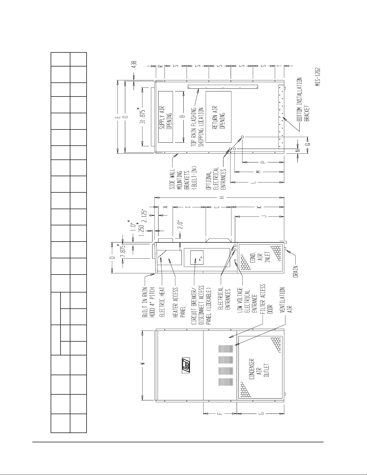
TABLE 2
FIGURE 1
UNIT DIMENSIONS
EFGIJKLMNOPQRSTABCB
DIMENSIONS OF BASIC UNIT (NOMINAL)
ylppuSnruteR
thgieH
)H(
htpeD
)D(
htdiW
)W(
ledoM
Manual 2100-193O
Page 6 of 26
03HW
FRONT VIEW BACK VIEWSIDE VIEW
002.83521.71365.0788.788.7288.3188.7200.0405.8157.5239.7157.6257.8252.9200.7257.291.9357.2241.991.400.2100.5
OPTIONAL TOP OUTLET (FACTORY INSTALLED ONLY) FOR WH30 AND WH36 MODELS ONLY.
63HW
*

2
---
---
---
---
---
---
---
---
eziSeriW
dnuorG
01
---
---
01
---
---
---
---
---
---
---
---
---
---
---
---
---
01
01
---
---
---
01
01
---
---
---
---
---
---
---
---
---
---
---
---
rewoPdleiF
eziSeriW
---
2
---
esuFlanretxE
tiucriCro
mumixaM
rekaerB
---
1
---
eriW
eriW
tiucriC
---
ATKCBTKCATKCBTKCATKCBTKCATKCBTKC
---
eziS
01
eziS
8
rekaerB
530508
yticapmA
muminiM
tiucriC
4
dnuorG
2
rewoP
TABLE 3
dleiF
2
lanretxE
roesuF
mumixaM
1
ELECTRICAL SPECIFICATIONS
---
---
---
---
---
---
---
---
---
---
---
---
---
---
---
---
---
210101
210101
025203
---
---
---
---
---
---
---
---
---
---
---
---
---
---
---
---
---
---
010101
01
8
520405
---
---
---
---
---
---
---
---
------
---
---
---
---
---
---
---
---
---
41
210101
41
210101
8
51
025203
---
01
--8
---
03
---
05
---
62
---
05
01
8
8
4
---
---
---
---
---
---
---
---
---
---
---
---
---
---
---
---
---
---
01
01
04
01
--6
---
03
---
06
---
62
---
35
01
8
6
4
060809
6
6
06
06
25
35
8
4
---
---
---
---
---
---
---
---
---
---
010101
01
888
520405
---
---
---
---
---
---
---
---
---
---
---
---
---
---
---
01
41
41
51
05
4
yticapmA
muminiM
tiucriC
42
.oN
detaR
111
dnAstloV
esahP
stiucriC
rewoP
dleiF
Z0A-,00A-103HW
91
05
67
111
1-802/032
50A-
Z0B-,00B-103HW
ledoM
3 01A-
01
91
111
42
62
723597
1
1
1
1-802/032
73
64
3-802/032
02
837405
38
2r
2ro1
111
o1
3-802/032
3-064
60B-
60C-
Z0C-,0
0C-103HW
3 90B-
3 90C-
50A-
Z0A-,00A-163HW
5 51C-
3 01A-
60B-
Z0B-,00B-163HW
5 51A-
11
0252
62
1
111
1
3-064
60C-
Z0C-,00C-163HW
5 51C-
5 51B-
3 90B-
3 90C-
National Electric Code (latest revision), Article 310 for power conductor sizing.
1 Maximum size of the time delay fuse or HACR type circuit breaker for protection of field wiring conductors.
2 Based on 75° copper wire. All wiring must conform to the National Electrical Code and all local codes.
3 Maximum KW that can operate with heat pump on these "Minimum Circuit Ampacity" values are to be used for sizing the field power conductors. Refer to the
power conductor sizing.
4 These “Minimum Circuit Ampacity” values are to be used for sizing the field power conductors. Refer to the National Electrical Code (latest version), Article 310 for
310 regarding Ampacity Adjustment Factors when more than three conductors are in a raceway.
Not available on dehumidification models.
5
CAUTION: When more than one field power conductor circuit is run through one conduit, the conductors must be derated. Pay special attention to note 8 of table
Not available in top outlet version.
Manual 2100-193O
Page 7 of 26
Refer to Table 12 for maximum static pressure available
for duct design.
Design the duct work according to methods given by the
Air Conditioning Contractors of America (ACCA).
When duct runs through unheated spaces, it should be
insulated with a minimum of one inch of insulation.
Use insulation with a vapor barrier on the outside of the
insulation. Flexible joints should be used to connect the
duct work to the equipment in order to keep the noise
transmission to a minimum.
A 1/4 inch clearance to combustible material for the
first three (3) feet of duct attached to the outlet air frame
is required. See Wall Mounting Instructions and
Figures 3, 4, 7 & 8 for further details.
Ducts through the walls must be insulated and all joints
taped or sealed to prevent air or moisture entering the
wall cavity.
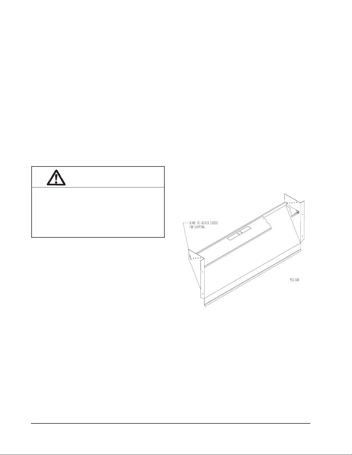
FRESH AIR INTAKE
All units are built with fresh air inlet slots punched in
the service panel.
If the unit is equipped with a fresh air damper assembly,
the assembly is shipped already attached to the unit.
The damper blade is locked in the closed position. To
allow the damper to operate, the maximum and
minimum blade position stops must be installed. See
Figure 2.
All capacity, efficiency and cost of operation
information as required for Department of Energy
“Energyguide” Fact Sheets is based upon the fresh air
blank-off plate in place and is recommended for
maximum energy efficiency.
The blank-off plate is available upon request from the
factory and is installed in place of the fresh air damper
shipped with each unit.
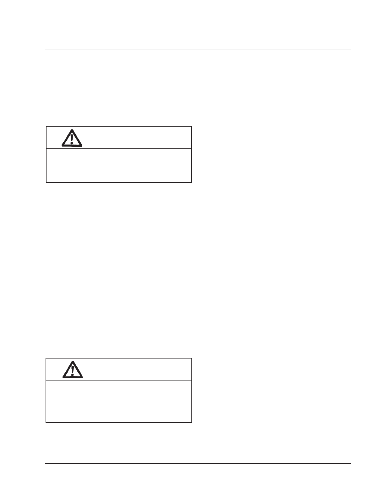
CAUTION
Some installations may not require any
return air duct. A metallic return air grille is
required with installations not requiring a
return air duct. The spacing between
louvers on the grille shall not be larger than
5/8 inches.
Any grille that meets the 5/8 inch louver criteria may be
used. It is recommended that Bard Return Air Grille Kit
RG-2 through RG-5 or RFG-2 through RFG-5 be
installed when no return duct is used. Contact
distributor or factory for ordering information. If using
a return air filter grille, filters must be of sufficient size
to allow a maximum velocity of 400 fpm.
NOTE: If no return air duct is used, applicable
installation codes may limit this cabinet to
installation only in a single story structure.
FILTERS
A 1-inch throwaway filter is supplied with each unit.
The filter slides into position making it easy to service.
This filter can be serviced from the outside by removing
the service door. A 1-inch washable filter and a 2-inch
pleated filter are also available as optional accessories.
The internal filter brackets are adjustable to
accommodate the two inch filter by loosening two
screws in each bracket assembly and sliding the brackets
apart to the required width and retightening the four
screws.
FIGURE 2
FRESH AIR DAMPER ASSEMBLY
CONDENSATE DRAIN
A plastic drain hose extends from the drain pan at the
top of the unit down to the unit base. There are
openings in the unit base for the drain hose to pass
through. In the event the drain hose is connected to a
drain system of some type, it must be an open or vented
type system to assure proper drainage.
Manual 2100-193O
Page 8 of 26
INSTALLATION INSTRUCTIONS
WALL MOUNTING INFORMATION
1. Two holes, for the supply and return air openings,
must be cut through the wall as shown in Figure 3.
2. On wood-frame walls, the wall construction must be
strong and rigid enough to carry the weight of the
unit without transmitting any unit vibration.
WARNING
Fire hazard can result if 1/4 inch clearance
to combustible materials for supply air duct
is not maintained. See Figure 3.
3. Concrete block walls must be thoroughly inspected
to insure that they are capable of carrying the
weight of the unit installed.
MOUNTING THE UNIT
1. These units are secured by wall mounting brackets
which secure the unit to the outside wall surface at
both sides. A bottom mounting bracket is provided
for ease of installation, but is not required.
2. The unit itself is suitable for “0” inch clearance, but
the supply air duct flange and the first 3 feet of supply
air duct require a minimum of 1/4 inch clearance to
combustible material. If a combustible wall, use a
minimum of 28½" x 8½" dimensions for sizing.
However, it is generally recommended that a 1-inch
clearance is used for ease of installation and
maintaining the required clearance to combustible
material. The supply air opening would then be
30" x 10". See Figures 3, 4, 7 and 8 for details.
3. Locate and mark lag bolt locations and bottom
mounting bracket location. See Figure 3.
4. Mount bottom mounting bracket, if used.
5. Hook top rain flashing under back bend of top. Top
rain flashing is shipped secured to the back of the unit
on the right side.
6. Position unit in opening and secure with 5/16 lag
bolts; use 7/8 inch diameter flat washers on the lag
bolts.
7. Secure rain flashing to wall and caulk across entire
length of top. See Figure 3.
8. For additional mounting rigidity, the return air and
supply air frames or collars can be drilled and
screwed or welded to the structural wall itself
(depending upon wall construction). Be sure to
observe required clearance if combustible wall.
9. On side-by-side installations, maintain a minimum of
20 inches clearance on right side to allow access to
heat strips and control panel and to allow proper
airflow to the outdoor coil. Additional clearance may
be required to meet local or national codes.
TOP OUTLET ONLY
1. Remove airframe angles from the back of the unit.
2. Coat angles with two 1/8" beads of silicone as shown.
Silicone is shipped in the control panel. See Figure 5.
3. Secure angles to the top of the unit with 14 screws
provided. Use prepunched holes provided. Do not
relocate. See Figure 5.
4. After installation of duct work, seal around airframe
and duct work to provide a rain tight seal.
5. It is strongly recommended, but not required, that this
unit be installed under a soffit area large enough to
shield the top of the unit. See Figure 6.
WARNING
Failure to provide the 1/4 inch clearance
between the supply duct and a combustible
surface for the first 3 feet of duct can result
in fire.
Manual 2100-193O
Page 9 of 26

FIGURE 3
MOUNTING INSTRUCTIONS
Manual 2100-193O
Page 10 of 26
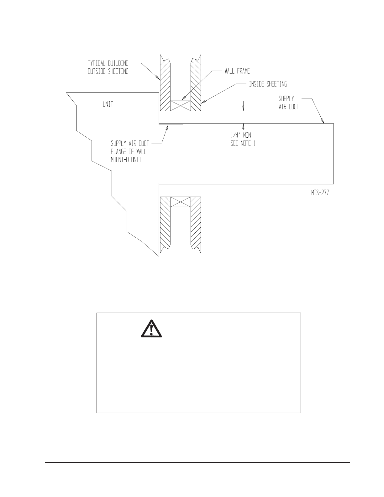
FIGURE 4
ELECTRIC HEAT CLEARANCE
Side section view of supply air duct for wall mounted unit showing 1/4" clearance to combustible surfaces.
WARNING
A minimum of 1/4" clearance must be maintained between the
supply air duct and combustible materials. This is required for
the fist three (3) feet of ducting.
It is important to insure that the 1/4" minimum spacing is
maintained at all points.
Failure to do this could result in overheating the combustible
material and may result in a fire.
Manual 2100-193O
Page 11 of 26

FIGURE 5
ATTACHING TOP OUTLET AIRFRAMES TO UNIT
FIGURE 6
UNIT WITH TOP OUTLET MOUNTED UNDER OVERHANG
Manual 2100-193O
Page 12 of 26

FIGURE 7
WALL-MOUNTING INSTRUCTIONS
SEE FIGURE 3 – MOUNTING INSTRUCTIONS
FIGURE 8
WALL-MOUNTING INSTRUCTIONS
SEE UNIT DIMENSIONS, FIGURE 1,
FOR ACTUAL DIMENSIONS
SEE FIGURE 1 FOR
DUCT DIMENSIONS
Manual 2100-193O
Page 13 of 26
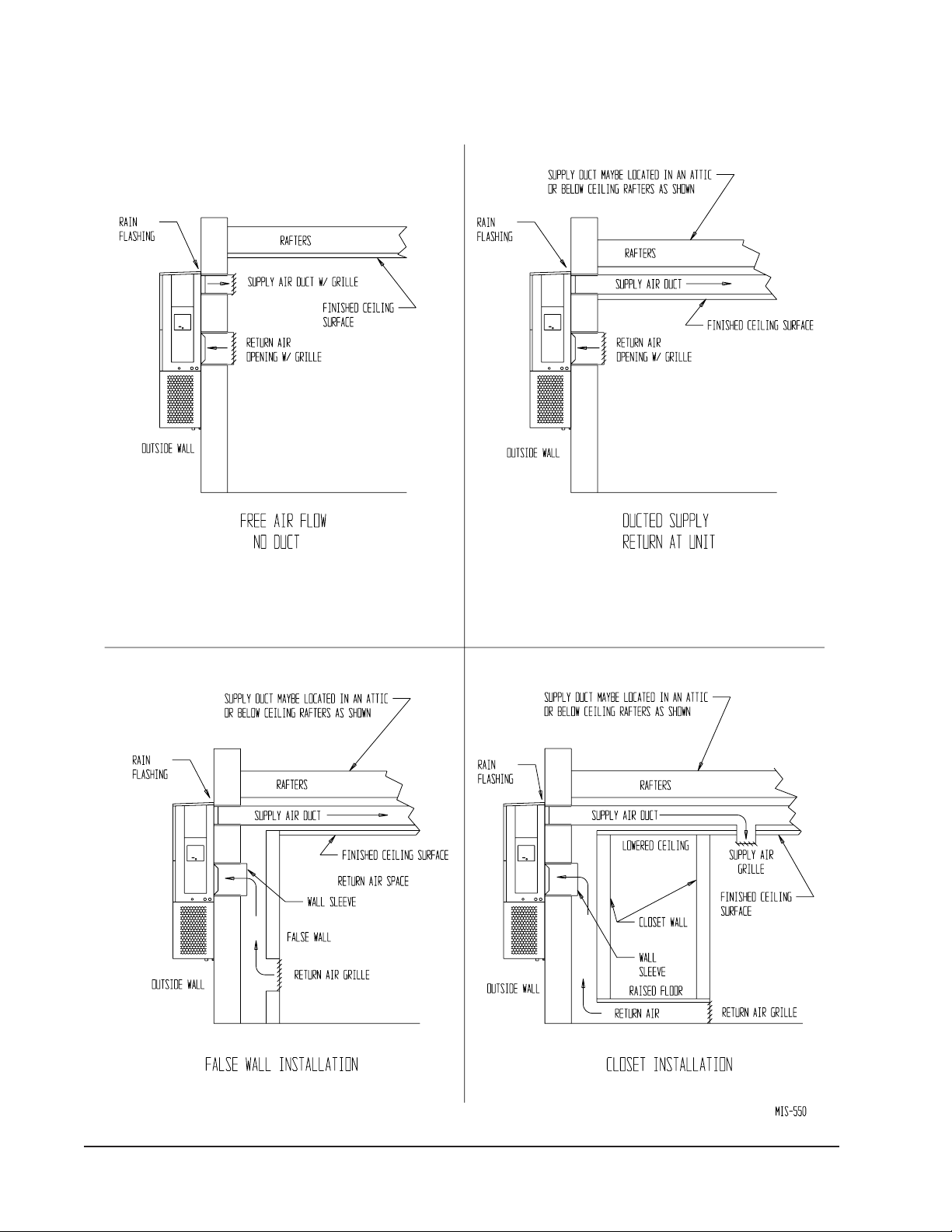
FIGURE 9
COMMON WALL-MOUNTING INSTALLATIONS
Manual 2100-193O
Page 14 of 26

WIRING — MAIN POWER
Refer to the unit rating plate for wire sizing information
and maximum fuse or “HACR Type” circuit breaker
size. Each outdoor unit is marked with a “Minimum
Circuit Ampacity”. This means that the field wiring
used must be sized to carry that amount of current.
Depending on the installed KW of electric heat, there
may be two field power circuits required. If this is the
case, the unit serial plate will so indicate. All models
are suitable only for connection with copper wire. Each
unit and/or wiring diagram will be marked “Use Copper
Conductors Only”. These instructions must be adhered
to. Refer to the National Electrical Code (NEC) for
complete current carrying capacity data on the various
insulation grades of wiring material. All wiring must
conform to NEC and all local codes.
The electrical data lists fuse and wire sizes (75ºC
copper) for all models, including the most commonly
used heater sizes. Also shown are the number of field
power circuits required for the various models with
heaters.
The unit rating plate lists a “Maximum Time Delay
Relay Fuse” or “HACR Type” circuit breaker that is to
be used with the equipment. The correct size must be
used for proper circuit protection and also to assure that
there will be no nuisance tripping due to the momentary
high starting current of the compressor motor.
The disconnect access door on this unit may be locked to
prevent unauthorized access to the disconnect. To
convert for the locking capability, bend the tab located
in the bottom left hand corner of the disconnect opening
under the disconnect access panel straight out. This tab
will now line up with the slot in the door. When shut, a
padlock may be placed through the hole in the tab
preventing entry.
If no motorized vent option is used, nine (9) wires
should be run from the thermostat subbase to the 24V
terminal board in the unit. A nine (9) conductor, 18
gauge copper color-coded thermostat cable is
recommended. If a motorized vent option is used,
terminal O1 on the unit low voltage terminal block will
also be used. This requires a ten (10) conductor
thermostat cable to be run. The connection points are
shown in Figure 10.
LOW VOLTAGE CONNECTIONS
These units use a grounded 24 volt AC low voltage
circuit.
The "R" terminal is the hot terminal and the "C"
terminal is grounded.
"G" terminal is the fan input.
"Y" terminal is the compressor input for cooling and
heat pump.
"B/W1" terminal is the reversing valve input. The
reversing valve must be energized for heating mode.
"R" terminal is 24 VAC hot.
"C" terminal is 24 VAC grounded.
"L" terminal is compressor lockout output. This
terminal is activated on a high or low pressure trip by the
electronic heat pump control. This is a 24 VAC output.
"W2" terminal is second stage heat (if equipped).
"01" terminal is the ventilation input. This terminal
energizes any factory installed ventilation option.
"E" terminal is the emergency heat input. This terminal
energizes the emergency heat relay.
WIRING — LOW VOLTAGE WIRING
230/208V, 1 phase and 3 phase equipment dual primary
voltage transformers. All equipment leaves the factory
wired on 240V tap. For 208V operation, reconnect from
240V to 208V tap. The acceptable operating voltage
range for the 240 and 208V taps are shown in Table 4:
TABLE 4
OPERATING VOLTAGE RANGE
PATEGNAR
V042612-352
V802781-022
NOTE: The voltage should be measured at the
field power connection point in the
unit and while the unit is operating at
full load (maximum amperage
operating condition.)
LOW VOLTAGE CONNECTIONS
FOR DDC CONTROL
Fan Only Energize G
Cooling Mode Energize Y, G
Heat Pump Heating Energize Y, G, B
2nd Stage Heating Energize G, W2, Y, B/W1
(if employed)
Ventilation Energize G, O1
Emergency Heat Energize B, W2, E, G
Manual 2100-193O
Page 15 of 26

FIGURE 10
LOW VOLTAGE WIRING
Manual 2100-193O
Page 16 of 26
TABLE 5
THERMOSTAT WIRE SIZE
remrofsnarT
AVALFeguaGeriW
553.2
mumixaM
ecnatsiD
teeFnI
eguag02
eguag81
eguag61
eguag41
eguag21
54
06
001
061
052

OPTIONAL OUTDOOR THERMOSTAT
APPLICATIONS
Thus, not requiring the optional compressor cut-off
thermostat or the electric heat cut-off thermostat option.
Since most equipment at the time of manufacture is not
designated for any specific destination of the country and
are installed in areas not approaching the lower outdoor
temperature range, outdoor thermostats are not factory
installed as standard equipment, but are offered as an
option. There are also different applications for applying
outdoor thermostats. The set point of either type of outdoor
thermostat application is variable with geographic region
and sizing of the heating equipment to the individual
structure. Utilization of the heating Application Data, and
the heat loss calculation of the building are useful in
determining the correct set points.
Temperature and Humidity Controller #8403-060, along
with the Outdoor Sensor option Part #8403-061, can be
used to:
•Limit minimum outdoor temperature for cooling option.
• Limit minimum outdoor temperature for heat pump option.
•Inhibit electric heat operation for heat pumps above
selected outdoor temperature.
FIGURE 11
COMPRESSOR CUTOFF THERMOSTAT WIRING
4 & 10KW 1 PH — 6 & 9KW 3 PH
OPTIONAL COMPRESSOR CUTOFF
THERMOSTAT (See Figures 11 and 12)
Heat pump compressor operation at outdoor temperatures
below 0°F are neither desirable nor advantageous in term
of efficiency. An outdoor thermostat can be applied to
take the mechanical heating (compressor) off line, and
send the (compressor) signal to energize electric heat in
its place (to make electric heat first stage heating). This
can also be applied to bank the quantity of available
electric heat. For example: A heat pump operates with
10KW second stage heat – once the outdoor thermostat
has switched then operates 15KW without the compressor
as first stage heat.
NOTE: The additional LAB (low ambient bypass) relay is
required to prevent heater operation during low
temperature cooling operation.
FIGURE 12
COMPRESSOR CUTOFF THERMOSTAT WIRING
15KW 1 PH & 3 PH
Manual 2100-193O
Page 17 of 26

ELECTRIC HEAT HOLD-OFF (See Figures 13
and 14)
In other applications, it is desirable to disable the
operation of the electric heat until outdoor temperatures
have reached a certain design point. This won't allow
the electric heat to come on as second stage heating
unless the outdoor temperature is below the set point of
the outdoor thermostat. This is done to maximize
ELECTRIC HEAT HOLD-OFF WIRING
4 & 10KW 1 PH — 6 & 9KW 3 PH
efficiency by utilizing the heat pump to bring the
conditioned space temperature up, rather than cycling on
the electric heat due a second stage call for heat from the
thermostat on start-up coming off a night setback
condition or someone increasing the thermostat set
point. (NOTE: Some programmable thermostats do
have a built-in time delay for pulling in second stage
heat when coming off setback conditions.)
FIGURE 13
Manual 2100-193O
Page 18 of 26
FIGURE 14
ELECTRIC HEAT HOLD-OFF WIRING
15KW 1 PH & 3 PH

TABLE 6
WALL THERMOSTAT
tatsomrehTserutaeFetanimoderP
850-3048
)1511D0225HT(
060-3048
)544-0211(
taehegats2,loocegats2
elbammargorP-noNcinortcelE
revoegnahclaunaMrootuA
taehegats3,loocegats2
cinortcelEelbammargorP
revoegnahclaunaMrootuA
tatsidimuHni-tliubhtiw
Manual 2100-193O
Page 19 of 26

START UP
IMPORTANT INSTALLER NOTE
For improved start-up performance, wash the indoor
coil with a dishwashing detergent.
FIGURE 15
START UP LABEL
IMPORTANT
CRANKCASE HEATERS
All units are provided with some form of compressor
crankcase heat.
All single and three phase models have an insertion
well-type heater located in the lower section of the
compressor housing. This is a self-regulating type
heater that draws only enough power to maintain the
compressor at a safe temperature.
Some form of crankcase heat is essential to prevent
liquid refrigerant from migrating to the compressor,
causing oil pump out on compressor start up and
possible valve failure due to compressing a liquid.
The decal in Figure 15 is affixed to all outdoor units
detailing start up procedure. This is very important.
Please read carefully.
SERVICE HINTS
1. Caution owner/operator to maintain clean air filters at
all times. Also, not to needlessly close off supply
and return air registers. This reduces airflow through
the system, which shortens equipment service life as
well as increasing operating costs.
2. Switching to heating cycle at 75°F or higher outside
temperature may cause a nuisance trip of the remote
reset high pressure switch. Turn thermostat off then
on to reset the high pressure switch.
3. The heat pump wall thermostats perform multiple
functions. Be sure that all function switches are
correctly set for the desired operating mode before
trying to diagnose any reported service problems.
4. Check all power fuses or circuit breakers to be sure
they are the correct rating.
5. Periodic cleaning of the outdoor coil to permit full
and unrestricted airflow circulation is essential.
SEQUENCE OF OPERATION
COOLING – Circuit R-Y makes at thermostat pulling
in compressor contactor, starting the compressor and
outdoor motor. The G (indoor motor) circuit is
automatically completed on any call for cooling
operation or can be energized by manual fan switch on
subbase for constant air circulation.
THESE PROCEDURES MUST BE
FOLLOWED AT INITIAL START UP
AND AT ANY TIME POWER HAS
BEEN REMOVED FOR 12 HOURS
OR LONGER.
TO PREVENT COMPRESSOR DAMAGE
WHICH MAY RESULT FROM THE PRESENCE
OF LIQUID REFRIGERANT IN THE
COMPRESSOR CRANKCASE:
1. Make certain the room thermostat is in the
"off" position (the compressor is not to
operate).
2. Apply power by closing the system
disconnect switch. This energizes the
compressor heater which evaporates the
liquid refrigerant in the crankcase.
3. Allow 4 hours or 60 minutes per poind of
refrigerant in the system as noted on the
unit rating plate, whichever is greater.
4. After properly elapsed time, the thermostat
may be set to operate the compressor.
5. Except as required for safety while
servicing. Do not open system
disconnect switch.
HEATING – A 24V solenoid coil on reversing valve
controls heating cycle operation. Two thermostat
options, one allowing “Auto” changeover from cycle to
cycle and the other constantly energizing solenoid coil
during heating season and thus eliminating pressure
equalization noise except during defrost, are to be used.
On “Auto” option, a circuit is completed from R-W1
and R-Y on each heating “on” cycle, energizing
reversing valve solenoid and pulling in compressor
contactor starting compressor and outdoor motor. R-G
also make starting indoor blower motor. Heat pump
heating cycle now in operation. The second option has
no “Auto” changeover position, but instead energizes
the reversing valve solenoid constantly whenever the
system switch on subbase is placed in “Heat” position,
the “B” terminal being constantly energized from R. A
thermostat demand for heat completes R-Y circuit
pulling in compressor contactor starting compressor and
outdoor motor.
R-G make starting indoor blower motor.
7961-061
Manual 2100-193O
Page 20 of 26

PRESSURE SERVICE PORTS
High and low pressure service ports are installed on all
units so that the system operating pressures can be
observed. Pressure tables can be found on Page 25
covering all models. It is imperative to match the
correct pressure table to the unit by model number.
DEFROST CYCLE
The defrost cycle is controlled by temperature and time
on the solid state heat pump control. See Figure 16.
When the outdoor temperature is in the lower 40° F
temperature range or colder, the outdoor coil
temperature is 32° F or below. This coil temperature is
sensed by the coil temperature sensor mounted near the
bottom of the outdoor coil. Once coil temperature
reaches 30° F or below, the coil temperature sensor
sends a signal to the control logic of the heat pump
control and the defrost timer will start.
After 60 minutes at 30° F or below, the heat pump
control will place the system in the defrost mode.
During the defrost mode, the refrigerant cycle switches
back to the cooling cycle, the outdoor motor stops,
electric heaters are energized, and hot gas passing
through the outdoor coil melts any accumulated frost.
When the temperature rises to approximately 57° F, the
coil temperature sensor will send a signal to the heat
pump control, which will return the system to heating
operations automatically.
If some abnormal or temporary condition such as a high
wind causes the heat pump to have a prolonged defrost
cycle, the heat pump control will restore the system to
heating operation automatically after 10 minutes.
The heat pump defrost control board has an option of 30,
60 or 90-minute setting. All models are shipped from
the factory on the 60-minute pin. If special
FIGURE 16
DEFROST CONTROL BOARD
circumstances require a change to another time, remove
the wire from the 60 minute terminal and reconnect to
the desired terminal. The manufacturer's
recommendation is for 60 minute defrost cycles. Refer
to Figure 16.
There is a cycle speed up jumper on the control. This
can be used to reduce the time between defrost cycle
operation without waiting for time to elapse.
Use a small screwdriver or other metallic object, or
another 1/4 inch QC, to short between the SPEEDUP
terminals to accelerate the HPC timer and initiate
defrost.
Be careful not to touch any other terminals with the
instrument used to short the SPEEDUP terminals. It
may take up to 10 seconds with the SPEEDUP terminals
shorted for the speedup to be completed and the defrost
cycle to start.
As soon as the defrost cycle kicks in remove the
shorting instrument from the SPEEDUP terminals.
Otherwise the timing will remain accelerated and run
through the 1-minute minimum defrost length sequence
in a matter of seconds and will automatically terminate
the defrost sequence.
There is an initiate defrost jumper (sen jump) on the
control that can be used at any outdoor ambient during
the heating cycle to simulate a 0° coil temperature. This
can be used to check defrost operation of the unit
without waiting for the outdoor ambient to fall into the
defrost region.
By placing a jumper across the SEN JMP terminals (a 1/4
inch QC terminal works best) the defrost sensor mounted
on the outdoor coil is shunted out and will activate the
timing circuit. This permits the defrost cycle to be
checked out in warmer weather conditions without the
outdoor temperature having to fall into the defrost region.
In order to terminate the defrost test the SEN JMP
jumper must be removed. If left in place too long the
compressor could stop due to the high
pressure control opening because of
high pressure condition created by
operating in the cooling mode with
outdoor fan off. Pressure will rise
fairly fast as there is likely no actual
frost on the outdoor coil in this
artificial test condition.
There is also a 5-minute compressor
time delay function built into the HPC.
This is to protect the compressor from
short cycling conditions. In some
instances it is helpful to the service
technician to override or speed up this
timing period, and shorting out the
SPEEDUP terminals for a few seconds
can do this.
Manual 2100-193O
Page 21 of 26

TROUBLESHOOTING
SOLID STATE HEAT PUMP CONTROL
TROUBLESHOOTING PROCEDURE
1. Turn on AC power supply to indoor and outdoor
units.
2. Turn thermostat blower switch to “Fan On” – the
indoor blower should start. (If it doesn't, troubleshoot
indoor unit and correct problem).
TROUBLESHOOTING
MOTPMYSSESUACELBISSOPKCEHCOTTAHWRIAPERROKCEHCOTWOH
ezigrenetonseod
rotomroodtuonaF
nurtonseod
gnitaehrognilooc(
ezigreneton
)ylnognitaeh(
otniogtonlliwtinU
tsorfed
)ylnognitaeh(
tsorfedfo
)ylnognitaeh(
Manual 2100-193O
Page 22 of 26
rotcatnocrosserpmoC
)gnitaehrognilooc(
evitcefed
.tcerroc
)tsorfedgnirudtpecxe
seodevlavgnisreveR
tuoemoctonlliwtinU
evitcefed
evitcefed
evitcefed
evitcefed
evitcefed
gniriwtiucriclortnoC,tinutanoitcennocRrofkcehC
tuokcolrosserpmoC.1
.2
trohsrosserpmoC
noitcetorpelcyc
lortnocpmuptaeH
evitcefedrotcatnoCliocdetrohsroneporofkcehC
tongnisahprewoP
evitcefedrotoMdetrohsroneporofkcehC
roticapacrotoM
lortnocpmuptaeH
evlavgnisreveR
evitcefedliocdionelos
lortnocpmuptaeH
rosneserutarepmeT
lortnocpmuptaehro
rosneserutarepmeT
lortnocpmuptaehro
TABLE 7
gnidniw
C-Bdna
3. Turn thermostat blower switch to “Auto” position.
Indoor blower should stop.
4. Set system switch to heat or cool. Adjust thermostat
to call for “Heat” or “Cool” – the indoor blower,
compressor and outdoor fan should start.
NOTE: If there was no power to 24 volt transformer, the
compressor and outdoor fan motor will not start
for 5 minutes. This is because of the compressor
short cycle protection.
C-RneewtebV42dna
neewtebV42rofkcehC
hgihssorcakcehC
.hctiwserusserp
elbissoprehtollakcehC
560-0012launaM.sesuac
gnidniwrotom
)CN-moC(lortnocpmup
pudeepsssorcarepmuJ
.etunimenonihtiw
.1
lortnocpmuptaehnoC-1L
.2
C-CCneewtebV42rofkcehC
lortnocpmuptaehnoC-Ydna
esahpnoDELderrofkcehC
).ylnostinuesahp3(.rotinom
kcehC.gnitarroticapackcehC
.roticapacdetrohsroneporof
taehnoyalernafssorcakcehC
liocdetrohsroneporofkcehCliocdionelosecalpeR
C-VRneewtebV42rofkcehC
.1
.2
rosneserutarepmettcennocsiD
.1
ssorcarepmujdnadraobmorf
nesdnaslanimretpudeeps
dluohssihT.slanimretpmuj
.2
ahguorhtogottinuehtesuac
.etunimenonihtiwelcyctsorfed
.1
esuacdluohssihT.slanimret
tsorfedfotuoemocottinueht
.2
lortnocpmuptaeh
.hctiws
sdnoces01retfarepmuj
lortnocpmuptaehecalpeR
rotcatnocecalpeR
rotomecalpeR
roticapacecalpeR
lortnocpmuptaehecalpeR
gniriwtiucriclortnockcehC
lortnocpmuptaehecalpeR
rosneserutarepmet
.lortnocpmuptaehecalper
.rosneserutarepmret
.lortnocpmuptaehecalper
rewopottinuroodtuootnoitcennocRnuR
tatsomrehtnrutC-LneewtebegatlovonfI
erusserphgihteserotniaganodnaffo
tonlliwdnaneposihctiwserusserphgihfI
.hctiwsersserphgihecalper,teser
pudeepsrepmuj,C-CCneewtebegatlovonfI
dluohsrewopsdnoces01nihtiwdnalanimret
pudeepsevomeR.C-CCneewtebraeppa
.tinuehtotsdaelrewopowthctiwS
ecalper,elcyctsorfedhguorhtseogtinufI
,elcyctsorfedhguorhtogtonseodtinufI
ecalper,elcyctsorfedfotuosemoctinufI
,elcyctsorfedfotuoemoctonseodtinufI

CHECKING TEMPERATURE SENSOR
OUTSIDE UNIT CIRCUIT
1. Disconnect temperature sensor from board and from
outdoor coil.
2. Use an ohmmeter and measure the resistance of the
sensor. Also use ohmmeter to check for short or
open.
3. Check resistance reading to chart of resistance use
sensor ambient temperature. (Tolerance of part is
± 10%.)
4. If sensor resistance reads very low, then sensor is
shorted and will not allow proper operation of the
heat pump control.
5. If sensor is out of tolerance, shorted, open or reads
very low ohms then it should be replaced.
TEMPERATURE "F" VS. RESISTANCE "R" OF TEMPERATURE SENSOR
FR FR FR FR
0.52-
0.42-
0.32-
0.22-
0.12-
0.02-
0.91-
0.81-
0.71-
0.61-
0.51-
0.41-
0.31-
0.21-
0.11-
0.01-
0.9-
0.8-
0.7-
0.6-
0.5-
0.4-
0.3-
0.2-
0.1-
0.0
0.1
0.2
0.3
0.4
0.5
0.6
0.7
0.8
0.9
0.01
0.11
0.21
178691
990091
585381
813771
982171
784561
409951
925451
553941
473441
675931
659431
605031
912621
980221
801811
272411
575011
010701
475301
062001
46079
18939
80019
93188
17358
99628
12108
23677
03257
01927
07607
70586
81466
99346
94426
56506
54785
0.31
0.41
0.51
0.61
0.71
0.81
0.91
0.02
0.12
0.22
0.32
0.42
0.52
0.62
0.72
0.82
0.92
0.03
0.13
0.23
0.33
0.43
0.53
0.63
0.73
0.83
0.93
0.04
0.14
0.24
0.34
0.44
0.54
0.64
0.74
0.84
0.94
0.05
58965
48255
04635
15025
41505
82094
09574
00264
55844
45534
59224
77014
89893
75783
25673
38563
84553
54543
47533
43623
32713
04803
68992
75192
55382
77572
32862
29062
38352
69642
03042
48332
85722
05122
16512
98902
53402
69891
0.35
0.25
0.35
0.45
0.55
0.65
0.75
0.85
0.95
0.06
0.16
0.26
0.36
0.46
0.56
0.66
0.76
0.86
0.96
0.07
0.17
0.27
0.37
0.47
0.57
0.67
0.77
0.87
0.97
0.08
0.18
0.28
0.38
0.48
0.58
0.68
0.78
0.88
47391
76881
57381
98971
43471
48961
74561
22161
01751
01351
12941
44541
77141
02831
47431
73131
01821
29421
38121
38811
19511
70311
13011
26701
10501
74201
00001
0679
6259
9929
7709
2688
3568
9448
0528
7508
9687
6867
0.98
0.09
0.19
0.29
0.39
0.49
0.59
0.69
0.79
0.89
0.99
0.001
0.101
0.201
0.301
0.401
0.501
0.601
0.701
0.801
0.901
0.011
0.111
0.211
0.311
0.411
0.511
0.611
0.711
0.811
0.911
0.021
0.121
0.221
0.321
0.421
7057
4337
5617
0007
0486
3866
1356
3836
9326
8906
1695
7285
7965
0755
6445
6235
8025
4905
2894
3784
7674
3664
2654
4644
7634
4724
2814
3904
6004
1293
8383
7573
8763
1063
6253
2543
Manual 2100-193O
Page 23 of 26

FAN BLADE SETTING DIMENSIONS
Shown in Figure 17 are the correct fan blade setting
dimensions for proper air delivery across the outdoor
coil.
The suction line temperatures in Table 9 are based upon
80ºF dry bulb/67ºF wet bulb (50 percent R.H.)
temperature and rated airflow across the evaporator
during cooling cycle.
Any service work requiring removal or adjustment in the
fan and/or motor area will require that the dimensions
below be checked and blade adjusted in or out on the
motor shaft accordingly.
FIGURE 17
FAN BLADE SETTING
TABLE 8
FAN BLADE DIMENSION
ledoMAnoisnemiD
103HW
163HW
"52.1
REMOVAL OF FAN SHROUD
1. Disconnect all power to unit.
2. Remove the screws holding both grilles, one on each
side of unit, and remove grilles.
3. Remove screws holding fan shroud to condenser and
bottom – nine (9) screws.
4. Unwire condenser fan motor.
5. Slide complete motor, fan blade, and shroud assembly
out the left side of the unit.
6. Service motor/fan as needed.
7. Reverse steps to reinstall.
REFRIGERANT CHARGE
The correct system R-22 charge is shown on the unit
rating plate. Optimum unit performance will occur with
a refrigerant charge resulting in a suction line
temperature (6 inches from compressor) as shown in
Table 9.
TABLE 9
SUCTION LINE TEMPERATURES
detaR
ledoM
103HW001,185-6556-36
163HW001,115-9486-66
wolfriA
DOF59
erutarepmeT
DOF28
erutarepmeT
TABLE 10
INDOOR BLOWER PERFORMANCE
CFM AT 230 VOLTS
163HW,103HW
.P.S.E
HnI2O
0./059539/593,1513,1
1./039519/043,1072,1
2./019588/582,1091,1
3./558038/502,1001,1
4./008557/011,1000,1
5./------/500,1078
6./------/------
deepSwoLdeepShgiH
/lioCyrDlioCteW/lioCyrDlioCteW
TABLE 11
CFM AND ESP
j
detaR
ledoM
103HW
163HW
Rated CFM and ESP on high speed tap
MFC
000,1
001,1
j
detaR
PSE
03.
03.
003,1-039
053,1-039
TABLE 12
MAXIMUM ESP OF OPERATION
ELECTRIC HEAT ONLY
teltuOtnorFteltuOpoT
woL
ledoM
00A
103HW
50A
163HW
01A
51A
00B
103HW
60B
163HW
90B
51B
00C
103HW
60C
163HW
90C
51C
Values shown are for units equipped with standard 1"
throwaway filter or 1" washable filter. Derate ESP by
.15 for 2" pleated filter.
deepS
05.
04.
53.
53.
05.
04.
53.
53.
05.
05.
03.
03.
hgiH
deepS
05.
05.
04.
04.
05.
05.
54.
54.
05.
05.
04.
04.
woL
deepS
05.
04.
52.
AN
05.
AN
03.
AN
05.
AN
53.
AN
05.
05.
04.
AN
05.
AN
04.
AN
05.
AN
54.
AN
dednemmoceR
egnaRwolfriA
hgiH
deepS
Manual 2100-193O
Page 24 of 26

TABLE 13
COOLING PRESSURE (PSI) – OUTDOOR TEMPERATURE °F
AIR TEMPERATURE ENTERING OUTDOOR COIL °F
riAnruteR
ledoM
103HW
163HW
erutarepmeTerusserP5708580959001501011511
BDged57
BWged26
BDged08
BWged76
BDged58
BWged27
BDged57
BWged26
BDged08
BWged76
BDged58
BWged27
ediSwoL
ediShgiH
ediSwoL
ediShgiH
ediSwoL
ediShgiH
ediSwoL
ediShgiH
ediSwoL
ediShgiH
ediSwoL
ediShgiH
67
87
08
532
942
362
18
38
58
142
552
962
88
09
29
052
462
972
96
17
37
012
622
242
37
67
87
612
232
842
97
18
48
322
042
652
18
38
48
58
78
772
192
503
913
333
78
88
09
19
39
482
892
213
723
39
59
79
89
001
492
803
323
833
353
57
67
87
08
28
752
372
092
603
323
08
28
48
58
78
462
182
792
413
68
88
09
29
49
372
092
803
523
243
88
743
49
143
653
101
863
38
933
98
133
843
59
063
TABLE 14
HEATING PRESSURE (PSI) – OUTDOOR TEMPERATURE °F
AIR TEMPERATURE ENTERING OUTDOOR COIL °F
riAnruteR
ledoM
103HW07
163HW07
erutarepmeTerusserP050151025203530454055506
o
o
ediSwoL
ediSwoL
12
52
82
23
63
93
34
74
15
55
95
ediShgiH
341
841
351
951
561
271
081
881
791
702
712
22
52
82
13
43
83
24
64
05
55
06
ediShgiH
541
251
951
761
771
681
791
802
022
332
642
Low side pressure ± 2 psig
High side pressure ± 5 psig
Tables are based upon rated CFM (airflow) across the evaporator coil and should be found under section titled
“Refrigerant Charge” on Page 24 in manual. If there is any doubt as to correct charge being in the system, the
charge should be removed, system evacuated and recharged to serial plate instructions
.
36
76
822
932
56
07
062
572
Manual 2100-193O
Page 25 of 26

TABLE 15
OPTIONAL ACCESSORIES
LEDOMNOITPIRCSED
50A-03HWHEsegakcaPretaeH 1 X
01A-03HWHEsegakcaPretaeH 1 X
50A-63HWHEsegakcaPretaeH 1 X
01A-63HWHEsegakcaPretaeH 1 X
51A-63HWHEsegakcaPretaeH 1 X
60B-30HWHEsegakcaPretaeH 1 XX
90B-30HWHEsegakcaPretaeH 1 XX
51B-30HWHEsegakcaPretaeH 1 X
60C-30HWHEsegakcaPretaeH 1 XX
90C-30HWHEsegakcaPretaeH 1 XX
51C-30HWHEsegakcaPretaeH 1 XX
3-POBetalPffOknalB
3-DAFBrepmaDriAhserFcirtemoraB XXXXXX
3-DAFMrepmaDriAhserFdezirotoM XXXXXX
3-VRCtsuahxEhtiwrotalitneVlaicremmoC XXXXXX
3-MFIEtsuahxEhtiwrezimonocE
WH301-A
XXXXXX
XXXXXX
WH301-B
WH301-C
WH361-A
WH361-B
WH361-C
3-HMC)CPL(lortnoCerusserPwoL
7-HMC)CAL(lortnoCtneibmAwoL XXXXXX
9-HMCCPL+CAL XXXXXX
A41-HMC)TDO(tatsomrehTroodtuO XXXXXX
51-CMC)KS(tiKtratSXX
10-DPMWtiKrekaerBtiucriCXX
Manual 2100-193O
Page 26 of 26
A3A-VREWrotalitneVyrevoceRygrenEXXXX
A3C-VREWrotalitneVyrevoceRygrenEXX
XXXXXX
A50-BCMWtiKrekaerBtiucriCX
B30-BCMWtiKrekaerBtiucriCX
A60-BCMWtiKrekaerBtiucriCX
X
 Loading...