


INSTALLATION INSTRUCTIONS
WALL MOUNTED
PACKAGE HEAT PUMPS
MODELS:
WH421
WH483
WH602
BARD MANUFACTURING COMPANY
Bryan, Ohio 43506
Since 1914...Moving ahead, just as planned.
Manual: 2100-399
Supersedes:
File: Volume III Tab 17
Date: 03-01-02
Copyright 2002

CONTENTS
Getting Other Information and Publications .......... 1
For more information, contact these publishers: ...... 1
Wall Mount General Information ............................. 2
Air Conditioner Wall Mount Model Nomenclature..... 2
Shipping Damage .................................................... 5
General ............................................................... 5
Duct Work ............................................................... 5
Filters ............................................................... 5
Fresh Air Intake........................................................ 6
Condensate Drain .................................................... 6
Installation Instructions ........................................... 7
Wall Mounting Information ....................................... 7
Mounting the Unit ..................................................... 7
Typical Installations .................................................. 7
Wiring – Main Power.............................................11
Wiring – Low Voltage Wiring.................................11
Thermostat Wiring ................................................. 12
Heat Anticipation.................................................... 12
Thermostat Indicator Lamps .................................. 13
Emergency Heat Position ...................................... 13
Compressor Malfunction ........................................ 13
Start Up ................................................................... 14
Important Installer Note.......................................... 14
High Pressure Switch............................................. 14
Three Phase Scroll Compressor Start Up
Information............................................................. 14
Phase Monitor........................................................ 15
Service Hints.......................................................... 15
Sequence of Operation.......................................... 15
Pressure Service Ports .......................................... 15
Defrost Cycle ......................................................... 15
Troubleshooting ..................................................... 17
Solid State Heat Pump Control
Troubleshooting Procedure.................................... 17
Checking T emperature Sensor Outdoor
Unit Circuit ............................................................. 18
Fan Blade Setting Dimensions ............................... 19
Removal of Fan Shroud......................................... 19
Refrigerant Charge ................................................ 19
Pressure Chart.................................................. 20-21
Optional Accessories ............................................. 21
Figures
Figure 1 Unit Dimensions ..................................... 3
Figure 2 Blower Damper Assembly...................... 6
Figure 3 Mounting Instructions.............................. 8
Figure 3A Electric Heat Clearance ......................... 8
Figure 4 Wall-Mounting Instructions ..................... 9
Figure 5 Wall-Mounting Instructions ..................... 9
Figure 6 Common Wall-Mounting Instructions.... 10
Figure 7 Unit 24V Terminal Board .......................1 1
Figure 8 Compressor Cutoff and Outdoor
Thermostat Wiring................................ 12
Figure 9 Start-Up Label...................................... 14
Figure 10 Defrost Control Board .......................... 16
Figure 1 1 Fan Blade Setting ................................ 19
Tables
Table 1 Electrical Specifications ......................... 2
Table 2 Electric Heat Table ................................. 4
Table 3 Thermostat Wire Size .......................... 12
Table 4 Wall Thermostat and
Subbase Combinations ........................ 13
Table 5 Troubleshooting.................................... 17
T able 6 Fan Blade Dimensions ......................... 19
T able 7 Suction Line T emperatures................... 19
Table 8 Recommended Operating Ranges ...... 19
Table 9 Indoor Blower Performance ................. 19
Table 10 Maximum ESP of Operation ................ 20
Table 11 Cooling Pressures................................ 20
Table 12 Heating Pressures................................ 21
Table 13 Optional Accessories ........................... 21
i

Getting Other Information and Publications
These publications can help you install the air
conditioner or heat pump. You can usually find these at
your local library or purchase them directly from the
publisher. Be sure to consult current edition of each
standard.
National Electrical Code ....................... ANSI/NFPA 70
Standard for the Installation ............... ANSI/NFPA 90A
of Air Conditioning and
Ventilating Systems
Standard for Warm Air ....................... ANSI/NFPA 90B
Heating and Air
Conditioning Systems
Load Calculation for........................ ACCA Manual J or
Residential Winter and Manual N
Summer Air Conditioning
Low Pressure, Low Velocity .......... ACCA Manual D or
Duct System Design for Winter Manual Q
and Summer Air Conditioning
FOR MORE INFORMATION, CONTACT
THESE PUBLISHERS:
ACCA Air Conditioning Contractors of America
1712 New Hampshire Ave. N.W.
Washington, DC 20009
Telephone: (202) 483-9370
Fax: (202) 234-4721
ANSI American National Standards Institute
11 West Street, 13th Floor
New York, NY 10036
Telephone: (212) 642-4900
Fax: (212) 302-1286
ASHRAEAmerican Society of Heating Refrigerating
and Air Conditioning Engineers, Inc.
1791 Tullie Circle, N.E.
Atlanta, GA 30329-2305
Telephone: (404) 636-8400
Fax: (404) 321-5478
NFPA National Fire Protection Association
Batterymarch Park
P.O. Box 9101
Quincy, MA 02269-9901
Telephone: (800) 344-3555
Fax: (617) 984-7057
Manufactured under the following U.S. patent numbers:
5,301,744; 5,002,116; 4,924,934; 4,875,520; 4,825,936;
4,432,409
Other patents pending.
Manual 2100-399
Page 1
WALL MOUNT GENERAL INFORMATION
HEAT PUMP WALL MOUNT MODEL NOMENCLATURE
MODEL NUMBER
WH 48 1 – A 10 X X X X X B
CAPACITY
42 – 3-1/2 T on
48 – 4 T on
60 – 5 T on
VOLTS & PHASE
A – 230/208/60-1
B – 230/208/60-3
C – 460/60-3
NOTE: For 0KW and circuit breakers (230/208 V) or pull disconnects (460 V) applications, insert 0Z in the KW field of model number.
REVISION
KW
00 – No KW
05 – 5 KW
06 – 6KW
09 – 9 KW
10 – 10 KW
15 – 15 KW
18 – 18 KW
20 – 20 KW
VENTILATION OPTIONS
X – Barometric Fresh Air Damper
(Standard)
B – Blank-off Plate
M – Motorized Fresh Air Damper
V – Commercial Room Ventilator
- Motorized with Exhaust
E – Economizer (Internal) - Fully
Modulating with Exhaust
R – Energy Recovery Ventilator -
Motorized with Exhaust
COLOR OPTIONS
X – Beige (Standard)
1 – White
2 – Mesa Tan
3 – Colonial White
4 – Buckeye Gray
FILTER OPTIONS
X – One Inch Throwaway
(Standard)
W – One Inch Washable
P – Two Inch Pleated
COIL OPTIONS
X – Standard
1 – Phenolic Coated Evaporator
2 – Phenolic Coated Condenser
3 – Phenolic Coated Evaporator
CONTROL MODULES
(See Chart Below)
and Condenser
OUTLET OPTIONS
X – Front (Standard)
TABLE 1
ELECTRIC HEAT TABLE
sledoM
AUTBA UTBAUTBAUTBAUTBA UTBAUTBAUTBA UTBAUTB
WK
4 7.61056314.4104201
58.02560711.81008218.02560711.8100821
64.41005025.21063512.708402
97.12006037.81030328.01007037.12006037.81030328.0100703
016.14031432.63006526.14031432.6300652
515.26002151.45004832.63002152.13004830.81002155.26002151.45004832.63002152.13004830.8100215
81 3.34004165.7305064
02 2.38052861.2700215
A-124HW
1-0421-8023-0423-8023-0641-0421-8023-0423-8023-064
B-124HW
B-384HW
C-124HW
A-384HW
A-206HW
B-384HW
B-206HW
C-384HW
C-206HW
Manual 2100-399
Page 2
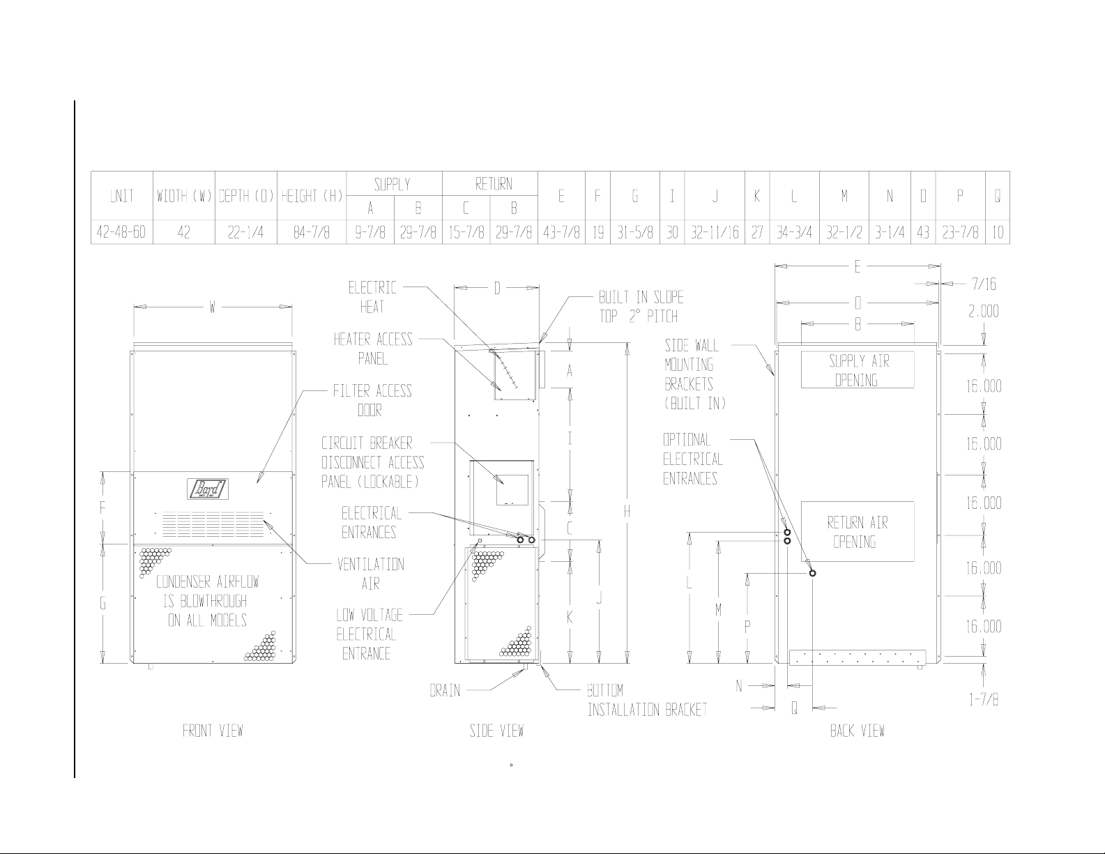
FIGURE 1
UNIT DIMENSIONS
Manual 2100-399
Page 3
MIS-411

3
3
3
3
3
3
3
3
3
TABLE 2
ELECTRICAL SPECIFICATIONS
TIUCRICELGNIS TIUCRICLAUD
4
detaR
stloV
ledoM
Z0A,00A-124HW
50A
01A
51A
Z0B,00B-124HW
60B
90B
51B
Z0C,00C-124HW
60C
90C
51C
Z0A,00A-384HW
40A
50A
01A
51A
02A
Z0B,00B-384HW
60B
90B
51B
81B
Z0C,00C-384HW
90C
51C
Z0A,00A-206HW
50A
01A
51A
02A
Z0B,00B-206HW
90B
51B
81B
Z0C,00C-206HW
90C
51C
3-064
3-064
3-064
.oN
dleiF
esahP&
1-802/032
3-802/032
1-802/032
3-802/032
1-802/032
3-802/032
rewoP
.stkC
1
1
1
1
1
1
1
1
1
1
1
1
1
1
1
1
1
1
1
1
1
1
1
1
1
1
1
43
2ro1
06
2ro1
68
2ro1
68
62
44
35
35
31
32
72
72
63
75
2ro1
26
1ro1
88
2ro1
88
2ro1
2ro1
1ro1
2ro1
2ro1
011
52
34
25
25
06
31
62
72
54
17
79
79
011
33
06
06
06
61
92
92
1
muminiM
tiucriC
yticapmA
05
07
09
09
53
05
06
06
02
52
03
03
05
06
07
53
05
06
06
06
51
03
03
06
09
54
06
06
06
02
53
53
2
mumixaM
lanretxE
roesuF
tiucriC
rekaerB
001
001
011
011
011
011
2
dleiF
rewoP
eriW
eziS
8
6
3
3
8
8
6
6
21
01
01
01
8
6
6
3
3
2
8
8
6
6
6
41
01
8
8
4
3
3
2
8
6
6
6
21
8
8
dnuorG
eriW
eziS
01
8
8
8
01
01
01
01
21
01
01
01
01
8
8
8
8
6
01
01
01
01
01
41
01
01
01
8
6
6
6
01
01
01
01
21
01
01
4
muminiM
tiucriC
yticapmA
AtkCBtkCAtkCBtkCAtkCBtkCAtkCBtkC
A/N
A/N
43
62
43
25
43
25
A/N
A/N
A/N
A/N
A/N
A/N
A/N
A/N
A/N
A/N
A/N
A/N
A/N
A/N
A/N
A/N
A/N
A/N
A/N
A/N
63
62
63
25
63
25
95
25
A/N
A/N
A/N
A/N
A/N
A/N
A/N
A/N
A/N
A/N
A/N
A/N
A/N
A/N
A/N
A/N
A/N
A/N
54
62
54
25
54
25
95
25
A/N
A/N
A/N
A/N
A/N
A/N
A/N
A/N
A/N
A/N
A/N
A/N
A/N
A/N
1
mumixaM
lanretxE
roesuF
A/N
A/N
05
03
05
06
05
06
A/N
A/N
A/N
A/N
A/N
A/N
A/N
A/N
A/N
A/N
A/N
A/N
A/N
A/N
A/N
A/N
A/N
A/N
A/N
A/N
05
03
05
06
05
06
06
06
A/N
A/N
A/N
A/N
A/N
A/N
A/N
A/N
A/N
A/N
A/N
A/N
A/N
A/N
A/N
A/N
A/N
A/N
06
06
06
06
06
06
06
06
A/N
A/N
A/N
A/N
A/N
A/N
A/N
A/N
A/N
A/N
A/N
A/N
A/N
A/N
2
rewoPdleiF
rekaerB.tkC
eziSeriW
A/N
A/N
8
8
8
A/N
A/N
A/N
A/N
A/N
A/N
A/N
A/N
A/N
A/N
8
8
8
6
A/N
A/N
A/N
A/N
A/N
A/N
A/N
A/N
A/N
8
8
8
6
A/N
A/N
A/N
A/N
A/N
A/N
A/N
A/N
01
01
6
01
6
01
A/N
A/N
A/N
A/N
A/N
A/N
A/N
A/N
A/N
A/N
A/N
A/N
A/N
A/N
A/N
A/N
A/N
A/N
A/N
A/N
01
01
6
01
6
01
6
01
A/N
A/N
A/N
A/N
A/N
A/N
A/N
A/N
A/N
A/N
A/N
A/N
A/N
A/N
A/N
A/N
A/N
A/N
01
01
6
01
6
01
6
01
A/N
A/N
A/N
A/N
A/N
A/N
A/N
A/N
A/N
A/N
A/N
A/N
A/N
A/N
2
eriWdnuorG
eziS
A/N
01
01
01
A/N
A/N
A/N
A/N
A/N
A/N
A/N
A/N
A/N
A/N
01
01
01
01
A/N
A/N
A/N
A/N
A/N
A/N
A/N
A/N
A/N
01
01
01
01
A/N
A/N
A/N
A/N
A/N
A/N
A/N
Maximum size of the time delay fuse or HACR type circuit breaker for protection of field wiring conductors.
Q
Based on 75°C copper wire. All wiring must conform to NEC and all local codes.
R
Maximum KW that can operate with heat pump on.
S
T
These Minimum Circuit Ampacity" values are to be used for sizing the field power conductors. Refer to the
National Electrical Code (latest version), article 310 for power conductor sizing. CAUTION: When more than one
field power conductor circuit is run through one conduit, the conductors must be derated. Pay special
attention to note 8 of table 310 regarding Ampacity Adjustment Factors when more than 3 conductors are
in a raceway.
Manual 2100-399
Page 4
SHIPPING DAMAGE
Upon receipt of equipment, the carton should be
checked for external signs of shipping damage. If
damage is found, the receiving party must contact the
last carrier immediately, preferably in writing,
requesting inspection by the carrier’s agent.
GENERAL
The equipment covered in this manual is to be installed
by trained, experienced service and installation
technicians.
The refrigerant system is completely assembled and
charged. All internal wiring is complete.
The unit is designed for use with or without duct work.
Flanges are provided for attaching the supply and return
ducts.
These instructions and any instructions packaged with
any separate equipment required to make up the entire
heat pump system should be carefully read before
beginning the installation. Note particularly “Starting
Procedure” and any tags and/or labels attached to the
equipment.
While these instructions are intended as a general
recommended guide, they do not supersede any national
and/or local codes in any way. Authorities having
jurisdiction should be consulted before the installation
is made. See Page 1 for information on codes and
standards.
Size of unit for a proposed installation should be based
on heat loss calculation made according to methods of
Air Conditioning Contractors of America (ACCA). The
air duct should be installed in accordance with the
Standards of the National Fire Protection Association
for the Installation of Air Conditioning and Ventilating
Systems of Other Than Residence Type, NFPA No.
90A, and Residence Type Warm Air Heating and Air
Conditioning Systems, NFPA No. 90B. Where local
regulations are at a variance with instructions, installer
should adhere to local codes.
DUCT WORK
Any heat pump is more critical of proper operating
charge and an adequate duct system than a straight air
conditioning unit. All duct work, supply and return,
must be properly sized for the design air flow
requirement of the equipment. Air Conditioning
Contractors of America (ACCA) is an excellent guide to
proper sizing. All duct work or portions thereof not in
the conditioned space should be properly insulated in
order to both conserve energy and prevent condensation
or moisture damage.
Refer to Table 10 for maximum static pressure available
for duct design.
Design the duct work according to methods given by the
Air Conditioning Contractors of America (ACCA).
When duct runs through unheated spaces, it should be
insulated with a minimum of one inch of insulation.
Use insulation with a vapor barrier on the outside of the
insulation. Flexible joints should be used to connect the
duct work to the equipment in order to keep the noise
transmission to a minimum.
A 1/4 inch clearance to combustible material for the first
three feet (3') of duct attached to the outlet air frame is
required. See Wall Mounting Instructions and Figures 4
and 4 for further details.
Ducts through the walls must be insulated and all joints
taped or sealed to prevent air or moisture entering the
wall cavity.
CAUTION
Some installations may not require any return
air duct. A metallic return air grille is required
with installations not requiring a return air
duct. The spacing between louvers on the
grille shall not be larger than 5/8 inches.
Any grille that meets the 5/8 inch louver criteria, may
be used. It is recommended that Bard Return Air Grille
Kit RG-2 thru RG-5 or RFG-2 thru RFG-5 be installed
when no return duct is used. Contact distributor or
factory for ordering information. If using a return air
filter grille, filters must be of sufficient size to allow a
maximum velocity of 400 fpm.
NOTE:If no return air duct is used, applicable
installation codes may limit this cabinet to
installation only in a single story structure.
FILTERS
A 1 inch throwaway filter is supplied with each unit.
The filter slides into position making it easy to service.
This filter can be serviced from the outside by removing
the service door. A 1 inch washable filter and 2 inch
pleated filter are also available as optional accessories.
The internal filter brackets are adjustable to
accommodate the 2 inch filter by bending down the tabs
to allow spacing for the 2 inch filters.
Manual 2100-399
Page 5

FRESH AIR INTAKE
All units are built with fresh air inlet slots punched in
the service panel.
If the unit is equipped with the fresh air damper
assembly, the assembly is shipped already attached to
the unit. The damper blade is locked in the closed
position. To allow the damper to operate, the maximum
and minium blade position stops must be installed. See
Figure 2.
All capacity, efficiency and cost of operation
information as required for Department of Energy
“Energyguide” Fact Sheets is based upon the fresh air
blank-off plate in place and is recommended for
maximum energy efficiency.
The blank-off plate is available upon request from the
factory and is installed in place of the fresh air damper
shipped with each unit.
BLOWER DAMPER ASSEMBLY
CONDENSATE DRAIN
A plastic drain hose extends from the drain pan at the
top of the unit down to the unit base. There are
openings in the unit base for the drain hose to pass
through. In the event the drain hose is connected to a
drain system of some type, it must be an open or vented
type system to assure proper drainage.
FIGURE 2
BLADE IS LOCKED
CLOSED FOR
SHIPPING
MIS-938
Manual 2100-399
Page 6

INSTALLATION INSTRUCTIONS
WALL MOUNTING INFORMATION
1. Two holes, for the supply and return air openings,
must be cut through the wall as shown in Figure 3.
2. On wood-frame walls, the wall construction must be
strong and rigid enough to carry the weight of the
unit without transmitting any unit vibration. See
Figures 4 and 5.
WARNING
Failure to provide the 1/4 inch clearance
between the supply duct and a combustible
surface for the first 3 feet of duct can result in
fire.
WARNING
Fire hazard can result if 1/4 inch clearance to
combustible materials for supply air duct is not
maintained. See Figure 3.
3. Concrete block walls must be thoroughly inspected to
insure that they are capable of carrying the weight of
the installing unit. See Figure 4.
MOUNTING THE UNIT
1. These units are secured by wall mounting brackets
which secure the unit to the outside wall surface at
both sides. A bottom mounting bracket is provided
for ease of installation, but it is not required.
2. The unit itself is suitable for “0” inch clearance, but
the supply air duct flange and the first 3 feet of
supply air duct require a minimum of 1/4 inch
clearance to combustible material. If a combustible
wall, use a minimum of 30-1/2" x 10-1/2"
dimensions for sizing. However, it is generally
recommended that a 1 inch clearance is used for ease
of installation and maintaining the required clearance
to combustible material. The supply air opening
would then be 32" x 12". See
Figures 3, 4 and 7 for details.
3. Locate and mark lag bolt locations and bottom
mounting bracket location. See Figure 4.
4. Mount bottom mounting bracket.
5. Hook top rain flashing under back bend of top. Top
rain flashing is shipped secured to the right side of
the back.
6. Position unit in opening and secure with 5/16 lag
bolts; use 7/8 inch diameter flat washers on the lag
bolts.
7. Secure rain flashing to wall and caulk across entire
length of top. See Figure 3.
8. For additional mounting rigidity, the return air and
supply air frames or collars can be drilled and
screwed or welded to the structural wall itself
(depending upon wall construction). Be sure to
observe required clearance if combustible wall.
9. On side by side installations, maintain a minimum of
20 inches clearance on right side to allow access to
heat strips and control panel, and to allow proper
airflow to the outdoor coil. Additional clearance may
be required to meet local or national codes.
TYPICAL INSTALLATIONS
See Figure 6 for common ways to install the wall-mount
unit.
Manual 2100-399
Page 7

FIGURE 3
MOUNTING INSTRUCTIONS
NOTE: It is recommended that a bead of silicone
caulking be placed behind the side mounting flanges
and under the top flashing at the time of installation.
ELECTRIC HEAT CLEARANCE
MIS-277
Manual 2100-399
Page 8
FIGURE 3A
Side section view of supply air
duct for wall mounted unit
showing 1/4 inch clearance to
combustible surfaces.
MIS-796
WARNING
• A minimum of 1/4 inch clearance must be
maintained between the supply air duct and
combustible materials. This is required for
the first 3 feet of ducting.
• It is important to insure that the 1/4 inch
minimum spacing is maintained at all points.
• Failure to do this could result in overheating
the combustible material and may result in
fire.

FIGURE 4
WALL-MOUNTING INSTRUCTIONS
SEE FIGURE 3 — MOUNTING INSTRUCTIONS
FIGURE 5
WALL-MOUNTING INSTRUCTIONS
SEE UNIT DIMENSIONS, FIGURE 1,
FOR ACTUAL DIMENSIONS
MIS-548
SEE FIGURE 1 FOR
DUCT DIMENSIONS
MIS-549
Manual 2100-399
Page 9

FIGURE 6
COMMON WALL-MOUNTING INSTALLATIONS
Manual 2100-399
Page 10
MIS-550

WIRING — MAIN POWER
Refer to the unit rating plate for wire sizing
information and maximum fuse or “HACR" type
circuit breaker size. Each outdoor unit is marked
with a “Minimum Circuit Ampacity”. This means
that the field wiring used must be sized to carry
that amount of current. Depending on the installed
KW of electric heat, there may be two field power
circuits required. If this is the case, the unit serial
plate will so indicate. All models are suitable only
for connection with copper wire. Each unit and/or
wiring diagram will be marked “Use Copper
Conductors Only”. These instructions must be
adhered to. Refer to the National Electrical Code
(NEC) for complete current carrying capacity data
on the various insulation grades of wiring material.
All wiring must conform to NEC and all local
codes.
The electrical data lists fuse and wire sizes
(75ºC copper) for all models, including the
most commonly used heater sizes. Also shown
are the number of field power circuits required
for the various models with heaters.
The unit rating plate lists a “Maximum Time
Delay Relay Fuse” or “HACR" type circuit
breaker that is to be used with the equipment.
The correct size must be used for proper circuit
protection and also to assure that there will be
no nuisance tripping due to the momentary high
starting current of the compressor motor.
NOTE:The voltage should be measured at the field power
connection point in the unit and while the unit is
operating at full load (maximum amperage
operating condition).
Nine (9) wires should be run from thermostat subbase to
the 24V terminal board in the unit. A nine conductor, 18
gauge copper, color-coded thermostat cable is
recommended. The connection points are shown in
Figure 7.
FIGURE 7
UNIT 24V TERMINAL BOARD
See Note 1
The disconnect access door on this unit may be
locked to prevent unauthorized access to the
disconnect. To convert for the locking
capability, bend the tab located in the bottom
left hand corner of the disconnect opening
under the disconnect access panel straight out.
This tab will now line up with the slot in the
door. When shut, a padlock may be placed
through the hole in the tab preventing entry.
See Start-up section for information on three
phase scroll compressor start-ups.
WIRING — LOW VOLTAGE WIRING
230/208V, 1 phase and 3 phase equipment dual
primary voltage transformers. All equipment
leaves the factory wired on 240V tap. For 208V
operation, reconnect from 240V to 208V tap.
The acceptable operating voltage range for the
240 and 208V taps are:
paTegnaR
042
802
612-352
781-022
MIS-440
FACTOR Y JUMPER
IMPORTANT NOTE:
Only the thermostat and subbase combinations as shown at
the right will work with this equipment. The thermostat and
subbase must be matched and the correct operation can be
assured only by proper selection and application of these
parts.
Note 1: 1F93-380 thermostat must be set to "Heat Pump"
mode to operate properly.
Press the program"RUN" button to make sure the
thermostat is in run program model.
Press time "FWD" and "BACK" at the same time to
enter User Configuration Menu.
Press and hold set "TIME" and "DAY" for about
3 seconds to enter Installer Menu.
The thermostat will display "MULTI STG"
Press the "UP" or "DOWN" button until the display
reads "HEAT PUMP"
Press program "RUN" button to resume operation.
Manual 2100-399
Page 11

TABLE 3
THERMOSTAT WIRE SIZE
mumixaM
remrofsnarT
AVALFeguaGeriW
553.2
eguag02
eguag81
eguag61
eguag41
eguag21
ecnatsiD
teeFnI
54
06
001
061
052
THERMOSTAT WIRING
COMPRESSOR CUTOFF THERMOSTAT AND
OUTDOOR THERMOSTATS
Heat pump compressor operation at outdoor
temperatures below 0° F are neither desirable nor
advantageous in terms of efficiency. Since most
equipment at time of manufacture is not designated for
any specific destination of the country and most of the
equipment is installed in areas not approaching the
lower outdoor temperature range, the compressor cutoffs
are not factory installed.
Outdoor thermostats are available to hold off various
banks of electric heat until needed as determined by
outdoor temperature. The set point of either type of
thermostat is variable with geographic region and
sizing of the heating equipment to the structure
Utilization of the Heating Application Data and the
heat loss calculation of the building are useful in
determining the correct set points.
HEAT ANTICIPATION
Both of the thermostats in Groups A and B below have
a fixed heat anticipator for stage 1 with no adjustment
required. Stage 2 has an adjustable anticipator for the
W2 connection and fixed for the W3 connection. Both
the W2 and W3 circuits are controlled by the stage 2
bulb. The only heat anticipator that needs to be
checked is stage 2 and it should be set to match the load
carried by the W2 circuit. The normal factory wiring
provides for only on electric heat contactor to be
controlled by W2, and the anticipator should be set at
.40A. If special field wiring is done, it is best to
actually measure the load but a good role is .40A for
each heat contactor controlled by W2.
FIGURE 8
COMPRESSOR CUTOFF AND OUTDOOR THERMOSTAT WIRING
4 - 10KW 1PH --- 6 & 9KW 3-PH
15 - 20KW 1-PH & 3-PH
Manual 2100-399
Page 12
MIS-409

TABLE 4
WALL THERMOSTAT AND SUBBASE COMBINATIONS
tatsomrehTesabbuSserutaeFtnanimoderP
540-3048
)1671A148T(
710-3048
)9211R478T(
810-3048
)4201N478T(
---
900-4048
)1811L476Q(
010-4048
)1621F476Q(
revoegnahclaunaM
revoegnahclaunaM
revoegnahclaunaMrootuA
blubyrucreM;taeh.gts2;looc.gts1
blubyrucreM;taeh.gts2;looc.gts2
blubyrucreM;taeh.gts2;looc.gts2
240-3048
)0701G1158T(
940-3048
)083-39F1(
(1) No automatic changeover position -- must be manually placed in heat or cool.
Reversing valve remains energized at all times system switch is in heat position
(except during defrost cycle). No pressure equalization noise when thermostat is
satisfied on either heating or cooling.
(2) Allows thermostat to control both heating and cooling operation when set in "Auto"
position. Reversing valve de-energizes at end of each "On" heating cycle.
---
---
taeh.gts2;looc.gts1
elbammargorP-noNcinortcelE
revoegnahclaunaMrootuA
taeh.gts2;looc.gts2
cinortcelEelbammargorP
revoegnahclaunaMrootuA
IMPORTANT NOTE:
Both thermostat and subbase combinations shown above in Groups A and B
incorporate the following features: Man-Auto fan switch, Off-Heat-Cool-Em.
Heat switch, and two (2) indicator lamps – one for emergency heat and one for
compressor malfunction.
THERMOSTAT INDICATOR LAMPS
The red lamp marked "Em. Ht." comes on and stays on
whenever the system switch is placed in the emergency
heat position. The green lamp marked "Check" will
come on if there is any problem that prevents the
compressor from running when it is supposed to be.
EMERGENCY HEAT POSITION
The operator of the equipment must manually place the
system switch in this position. This is done when there
is a know problem with the unit, or when the green
"Check" lamp comes on indicating a problem.
COMPRESSOR MALFUNCTION LIGHT
Actuation of the green "Check" lamp is accomplished
by a relay output from the heat pump control board
which is factory installed. Any condition such as loss
of charge, high head pressure, etc., that will prevent
compressor for operating will cause green lamp to
activate. This is a signal to the operator of the
equipment to place system in emergency heat position.
Manual 2100-399
Page 13

START UP
IMPORTANT INSTALLER NOTE
For improved start-up performance, wash the indoor
coil with a dishwashing detergent.
CRANKCASE HEATERS
WA421 units are provided with compressor crankcase
heat. WH602 and WH483 units are not provided with
crankcase heat. These units utilize scroll compressors
which do not require crankcase heat in this application.
The WH421 models have an insertion well-type heater
located in the lower section of the compressor housing
this is a self-regulating type heater that draws only
enough power to maintain the compressor at a safe
temperature on these units.
Some form of crankcase heat is essential to prevent
liquid refrigerant from migrating to the compressor,
causing oil pump out on compressor start-up and
possible valve failure due to compressing a liquid.
The decal in Figure 9 is affixed to all WA421 units
detailing start-up procedure. This is very important.
Please read carefully.
HIGH PRESSURE SWITCH
The WH483 and WH602 models are supplied with a
remote reset high pressure switch. If tripped, this
pressure switch may be reset by turning the thermostat
off then back on again.
THREE PHASE SCROLL COMPRESSOR
START UP INFORMATION
Scroll compressors, like several other types of
compressors, will only compress in one rotational
direction. Direction of rotation is not an issue with
single phase compressors since they will always start
and run in the proper direction.
However, three phase compressors will rotate in either
direction depending upon phasing of the power. Since
there is a 50-50 chance of connecting power in such a
way as to cause rotation in the reverse direction,
verification of proper rotation must be made. All three
phase units incorporate a phase monitor to ensure proper
field wiring. See the Phase Monitor" on page 15 of this
manual.
Verification of proper rotation must be made any time
a compressor is change or rewired. If improper rotation
is corrected at this time there will be no negative impact
on the durability of the compressor. However, reverse
operation for over one hour may have a negative impact
on the bearing due to oil pump out.
FIGURE 9
START UP LABEL
IMPORTANT
THESE PROCEDURES MUST BE
FOLLOWED A T INITIAL ST ART UP
AND AT ANY TIME POWER HAS
BEEN REMOVED FOR 12 HOURS
OR LONGER.
TO PREVENT COMPRESSOR DAMAGE
WHICH MAY RESULT FROM THE PRESENCE OF LIQUID REFRIGERANT IN THE
COMPRESSOR CRANKCASE:
1. MAKE CERT AIN THE ROOM THERMOST A T IS IN THE “OFF“ POSITION. (THE
COMPRESSOR IS NOT TO OPERA TE.)
2. APPLY POWER BY CLOSING THE
SYSTEM DISCONNECT SWITCH.
THIS ENERGIZES THE COMPRESSOR HEATER WHICH EVAPORATES
THE LIQUID REFRIGERANT IN THE
CRANKCASE.
3. ALLOW 4 HOURS OR 60 MINUTES
PER POUND OF REFRIGERANT IN
THE SYSTEM AS NOTED ON THE
UNIT RATING PLATE, WHICHEVER IS
GREATER.
4. AFTER PROPER ELAPSED TIME THE
THERMOSTA T MA Y BE SET TO OPERATE THE COMPRESSOR.
5. EXCEPT AS REQUIRED FOR SAFETY
WHILE SERVICING, DO NOT OPEN
SYSTEM DISCONNECT SWITCH.
7961-411
NOTE:If compressor is allowed to run in reverse
rotation for several minutes, the compressor's
internal protector will trip.
All three phase ZR3 compressors are wired identical
internally. As a result, once the correct phasing is
determined for a specific system or installation,
connecting properly phased power leads to the same
Fusite terminal should maintain proper rotation
direction.
Verification of proper rotation direction is made by
observing that suction pressure drops and discharge
pressure rises when the compressor is energized.
Reverse rotation also results in an elevated sound level
over that with correct rotations, as well as, substantially
reduced current draw compared to tabulated values.
The direction of rotation of the compressor may be
changed by reversing any two line connections to the
unit.
Manual 2100-399
Page 14

PHASE MONITOR
All units with three phase compressors are equipped
with a 3 phase line monitor to prevent compressor
damage due to phase reversal.
The phase monitor in this unit is equipped with two
LEDs. If the Y signal is present at the phase monitor
and phases are correct, the green LED will light. If
phases are reversed, the red fault LED will be lit and
compressor operation is inhibited.
now in operation. The second option has no "Auto"
changeover position, but instead energizes the reversing
valve solenoid constantly whenever the system switch
on subbase is placed in "Heat" position, the "B"
terminal being constantly energized from R. A
Thermostat demand for heat completes r-Y circuit,
pulling in compressor contactor starting compressor and
outdoor motor. R-G also make starting indoor blower
motor.
If a fault condition occurs, reverse two of the supply
leads to the unit. Do not reverse any of the unit factory
wires as damage may occur.
SERVICE HINTS
1. Caution homeowner to maintain clean air filters at all
times. Also, not to needlessly close off supply and
return air registers. This reduces air flow through the
system, which shortens equipment service life as
well as increasing operating costs.
2. Switching to heating cycle at 75° F or higher outside
temperature may cause a nuisance trip of the remote
reset high pressure switch. Turn thermostat off, then
on to reset the high pressure switch.
3. The heat pump wall thermostats perform multiple
functions. Be sure that all function switches are
correctly set for the desired operating mode before
trying to diagnose any reported service problems.
4. Check all power fuses or circuit breakers to be sure
they are the correct rating.
5. Periodic cleaning of the outdoor coil to permit full and
unrestricted airflow circulation is essential.
SEQUENCE OF OPERATION
COOLING –
compressor contactor, starting the compressor and
outdoor motor. The G (indoor motor) circuit is
automatically completed on any call for cooling
operation or can be energized by manual fan switch on
subbase for constant air circulation.
HEATING –
controls heating cycle operation. Two thermostat
options, one allowing "Auto" changeover from cycle to
cycle and the other constantly energizing solenoid coil
during heating season, and thus eliminating pressure
equalization noise except during defrost, are to be used.
On "Auto" option a circuit is completed from R-W1 and
R-Y on each heating "on" cycle, energizing reversing
valve solenoid and pulling in compressor contactor
starting compressor and outdoor motor. R-G also make
starting indoor blower motor. Heat pump heating cycle
Circuit R-Y makes at thermostat pulling in
A 24V solenoid coil on reversing valve
PRESSURE SERVICE PORTS
High and low pressure service ports are installed on all
units so that the system operating pressures can be
observed. Pressure tables can be found later in the
manual covering all models on both cooling and heating
cycles. It is imperative to match the correct pressure
curve to the unit by model number.
DEFROST CYCLE
The defrost cycle is controlled by temperature and time
on the solid state heat pump control.
When the outdoor temperature is in the lower 40° F
temperature range or colder, the outdoor coil
temperature is 32° F or below. This coil temperature is
sensed by the coil sensor mounted near the bottom of
the outdoor coil. Once coil temperature reaches 30° F
or below, the coil sends a signal to the control logic of
the heat pump control and the defrost timer will start.
After 60 (90 or 30) minutes at 30° F or below, the heat
pump control will place the system in the defrost mode.
During the defrost mode, the refrigerant cycle switches
back to the cooling cycle, the outdoor motor stops,
electric heaters are energized, and hot gas passing
through the outdoor coil melts any accumulated frost.
When the temperature rises to approximately 57° F, the
coil sensor will send a signal to the heat pump control
which will return the system to heating operations
automatically.
If some abnormal or temporary conditions such as a
high wind caused the heat pump to have a prolonged
defrost cycle, the heat pump control will restore the
system to heating operating automatically after 10
minutes.
There is a cycle SPEEDUP jumper on the control. This
can be used to reduce the time between defrost cycle
operation without waiting for time to elapse.
Use a small screwdriver or other metallic object, or
another 1/4 inch QC to short between the SPEEDUP
terminals to accelerate the HPC timer and initiate
defrost. Be careful not to touch any other terminals
with the instrument used to short the SPEEDUP
terminals. It may take up to 10 seconds with the
SPEEDUP terminals shorted for the speedup to be
completed and the defrost cycle to start.
Manual 2100-399
Page 15

As soon as the defrost cycle kicks in, remove the
shorting instrument from the SPEEDUP terminals.
Otherwise the timing will remain accelerated and run
through the 10-minute maximum defrost length
sequence in a matter of seconds and will automatically
terminate the defrost sequence.
There is an initial defrost (SEN JMP) jumper on the
control that can be used at any outdoor ambient during
the heating cycle to simulate a 0° coil temperature.
This can be used to check defrost operation of the unit
without waiting for the outdoor ambient to fall into the
defrost region.
The jumper connection (SEN JMP) on the heat Pump
Control (HPC) that can be used during the heating cycle
to simulate a 0 degree coil condition and initiate the
defrost sequence. By placing a jumper across the
SEN JMP terminals (1/4 inch QC terminal works best)
the defrost sensor mounted on the outdoor coil is
shunted out and will activate the timing circuit. This
permits the defrost cycle to be checked out in warmer
weather conditions without the outdoor temperature
having to fall into the defrost region.
There are three time settings on the HPC — 30, 60 or
on minutes. These are elapsed run-time values, and the
outdoor coil temperature sensor must be below the 30
degree equivalent resistance value for the timer to
accumulate time towards the actual defrost cycle event.
Using the SEN JMP terminals will force the timer to
run continuously.
The next event is the actual defrost cycle when the
reversing valve shifts the refrigerant system back to the
cooling mode, and the outdoor fan motor is turned off
to speed the heating of the outdoor coil and melting of
any accumulated frost. The SPEEDUP terminals can be
used to reduce the 30,60 or 90 minute real-time periods
to a matter of seconds. Electric heat is typically turned
on to temper the supply air temperature being delivered
into the building during the defrost cycle.
There is also a 5-minute compressor time delay
function built into the HPC. This is to protect the
compressor from short cycling conditions. In some
instances it is helpful to the service technician to
override or speedup this timing period, and shorting out
the SPEEDUP terminals for a few seconds can do this.
FIGURE 10
DEFROST CONTROL BOARD
Manual 2100-399
Page 16

TROUBLESHOOTING
SOLID STATE HEAT PUMP CONTROL
TROUBLESHOOTING PROCEDURE
1. Turn on AC power supply to indoor and outdoor
units.
2. Turn thermostat blower switch to fan "on" – the
indoor blower should start. (If it doesn't,
troubleshoot indoor unit and correct problem).
3. Turn thermostat blower switch to auto position.
Indoor blower should stop.
TROUBLESHOOTING
motpmySsesuaCelbissoPkcehCottahWriapeRrokcehCotwoH
rosserpmoC
tonseodrotcatnoc
rognitaeh(ezigrene
)gnilooc
noitcetorp
evitcefed
tcerroc
rotomroodtuonaF
nurtonseod
gnitaehrognilooc(
gnirudtpecxe
)tsorfed
evlavgnisreveR
ezigrenetonseod
)ylnognitaeh(
otniogtonlliwtinU
tsorfed
)ylnognitaeh(
emoctonlliwtinU
tsorfedfotuo
)ylnognitaeh(
evitcefed
evitcefed
evitcefed
evitcefed
evitcefed
gniriwtiucriclortnoCtinutaoitcennocRrofkcehC
tuokcolrosserpmoC.1
.2
elcyctrohsrosserpmoC
lortnocpmuptaeH
evitcefedrotcatnoCliocdetrohsroneporofkcehC
tongnisahprewoP
evitcefedrotoMdetrohsroneporofkcehC
roticapacrotoM
lortnocpmuptaeH
dionelosevlavgnisreveR
evitcefedlioc
lortnocpmuptaeH
rorosneserutarepmeT
lortnocpmuptaeh
rorosneserutarepmeT
lortnocpmuptaeh
TABLE 5
lortnoc
.hctiws
.gnidniw
.gnidniwrotom
.C-Bdna
.etunimeno
4. Set system to heat or cool. Adjust thermostat to call
for heat or cool – the indoor blower, compressor,
and outdoor fan should start.
NOTE:If there was no power to 24 volt transformer, the
compressor and outdoor fan motor will not start
for 5 minutes. This is because of the compressor
short cycle protection.
C-Rneewtebtlov42dna
neewtebV42rofkcehC
pmuptaehnoC-1L
elbissoprehtollakcehC
560-0012launaM.sesuac
noyalernafssorcakcehC
.1
eruserphgihssorcakcehC
.2
C-CCneewtebV42rofkcehC
.lortnocpmuptaehnoC-Ydna
esahpnoDELderrofkcehC
.)ylnostinuesahp3(rotinom
kcehC.gntarroticapackcehC
.roticapacdetrohsroneporof
.)CN-moC(lortnocpmuptaeh
.liocdetrohsroneporofkcehC
C-VRneewtebV42rofkcehC
.1
.2
erutarepmettcennocsiD
sihT.slanimretpmujnes
ogottinuehtesuracdluohs
pudeepsssorcarepmuJ
.etunimenonihtiw
.1
repmujdnadraobmorfrosnes
dnaslanimretpudeepsssorca
.2
nihtiwelcyctsorfedahguorht
.1
esuacdluohssihT.slanimret
tsorfedfotuoemocottinueht
.2
.lortnocpmup
erusserphgihteserotniaganodnaffo
.hctiws
.hctiwserusserphgihecalper,teser
evomeR.C-CCneewtebraeppadluohs
.sdnoces01retfarepmujpudeeps
.lortnocpmuptaehecalpeR
.rotcatnocecalpeR
.tinuehtotsdelrewopowthctiwS
.rotomecalpeR
.roticapacecalpeR
.lortnocpmuptaehecalpeR
.lioCdionelosecalpeR
.gniriwtiucriclortnockcehC
.lortnocpmuptaehecalpeR
.rosneserutarepmet
.lortnocpmuptaehecalper
.rosneserutarepmet
tsorfedfotuoemoctonseodtinufI
.lortnocpmuptaehecalper,elcyc
taehrewopottinuroodtuootnoitcennocRnuR
tatsomrehtnrut,C-1LneewtebegatlovonfI
tonlliwdnaneposihctiwserusserphgihfI
deepsrepmuj,C-CCneewtebegatlovtonfI
rewopsdnoces01nihtiwdna,lanimretpu
ecalper,elcyctsorfedhguorhtseogtinufI
,elcyctsorfedhguorhtogtonseodtinufI
ecalperelcyctsorfedfotuosemoctinufI
Manual 2100-399
Page 17

CHECKING TEMPERATURE SENSOR
OUTSIDE UNIT CIRCUIT
1. Disconnect temperature sensor from board and from
outdoor coil.
2. Use an ohmmeter and measure the resistance of the
sensor. Also use ohmmeter to check for short or
open.
3. Check resistance reading to chart of resistance. Use
sensor ambient temperature. (Tolerance of part is
± 10%.)
4. If sensor resistance reads very low, then sensor is
shorted and will not allow proper operation of the
heat pump control.
5. If sensor is out of tolerance, shorted, open or reads
very low ohms then it should be replaced.
TEMPERATURE F VS. RESISTANCE R OF TEMPERATURE SENSOR
FR FR FR FR
0.52-
0.42-
0.32-
0.22-
0.12-
0.02-
0.91-
0.81-
0.71-
0.61-
0.51-
0.41-
0.31-
0.21-
0.11-
0.01-
0.9-
0.8-
0.7-
0.6-
0.5-
0.4-
0.3-
0.2-
0.1-
0.0
0.1
0.2
0.3
0.4
0.5
0.6
0.7
0.8
0.9
0.01
0.11
0.21
178691
990091
585381
813771
982171
784561
409951
925451
553941
473441
675931
659431
605031
912621
980221
801811
272411
575011
010701
475301
062001
46079
18939
80019
93188
17358
99628
12108
23677
03257
01927
07607
70586
81466
99346
94426
56506
54785
0.31
0.41
0.51
0.61
0.71
0.81
0.91
0.02
0.12
0.22
0.32
0.42
0.52
0.62
0.72
0.82
0.92
0.03
0.13
0.23
0.33
0.43
0.53
0.63
0.73
0.83
0.93
0.04
0.14
0.24
0.34
0.44
0.54
0.64
0.74
0.84
0.94
0.05
58965
48255
04635
15025
41505
82094
09574
00264
55844
45534
59224
77014
89893
75783
25673
38563
84553
54543
47533
43623
32713
04803
68992
75192
55382
77572
32862
29062
38352
69642
03042
48332
85722
05122
16512
98902
53402
69891
0.35
0.25
0.35
0.45
0.55
0.65
0.75
0.85
0.95
0.06
0.16
0.26
0.36
0.46
0.56
0.66
0.76
0.86
0.96
0.07
0.17
0.27
0.37
0.47
0.57
0.67
0.77
0.87
0.97
0.08
0.18
0.28
0.38
0.48
0.58
0.68
0.78
0.88
47391
76881
57381
98971
43471
48961
74561
22161
01751
01351
12941
44541
77141
02831
47431
73131
01821
29421
38121
38811
19511
70311
13011
26701
10501
74201
00001
0679
6259
9929
7709
2688
3568
9448
0528
7508
9687
6867
0.98
0.09
0.19
0.29
0.39
0.49
0.59
0.69
0.79
0.89
0.99
0.001
0.101
0.201
0.301
0.401
0.501
0.601
0.701
0.801
0.901
0.011
0.111
0.211
0.311
0.411
0.511
0.611
0.711
0.811
0.911
0.021
0.121
0.221
0.321
0.421
7057
4337
5617
0007
0486
3866
1356
3836
9326
8906
1695
7285
7965
0755
6445
6235
8025
4905
2894
3784
7674
3664
2654
4644
7634
4724
2814
3904
6004
1293
8383
7573
8763
1063
6253
2543
Manual 2100-399
Page 18

FAN BLADE SETTING DIMENSIONS
ledoM
detaR
MFC
*
detaR
PSE
*
dednemmoceR
egnaRwolFriA
124HW004103.0511--0061
384HW055102.5821--0571
206HW007103.5731--0591
Shown in the drawing in Figure 11 are the correct fan
blade setting dimensions for proper air delivery across
the outdoor coil.
Any service work requiring removal or adjustment in
the fan and/or motor area will require that the
dimensions below be checked and blade adjusted in or
out on the motor shaft accordingly.
FIGURE 11
FAN BLADE SETTING
TABLE 6
FAN BLADE DIMENSIONS
ledoMAnoisnemiD
124HW
384HW
206HW
57.1
MIS-1190
REMOVAL OF FAN SHROUD
1. Disconnect all power to unit.
2. Remove the screws holding both grilles – one on
each side of unit – and remove grilles.
3. Remove screws holding fan shroud to condenser and
bottom – (9) screws.
4. Unwire condenser fan motor.
5. Slide complete motor, fan blade, and shroud
assembly out the left side of the unit.
6. Service motor/fan as needed.
7. Reverse steps to reinstall.
REFRIGERANT CHARGE
The correct system R-22 charge is shown on the unit
rating plate. Optimum unit performance will occur with
a refrigerant charge resulting in a suction line
temperature (6 inches from compressor) as shown in the
Table 7.
TABLE 7
SUCTION LINE TEMPERATURES
detaR
ledoM
124HW
384HW
206HW
wolfriA
0041
0551
0071
The suction line temperatures in Table 7 are based upon
80ºF dry bulb/67 degrees F wet bulb (50 percent R.H.)
temperature and rated airflow across the evaporator
during cooling cycle.
TABLE 8
RECOMMENDED OPERATING RANGES
* Rated CFM and ESP on high speed tap.
.D.OF°59
erutarepmeT
45--25
55--35
45--25
.D.OF°28
46--26
46--26
36--16
erutarepmeT
.P.S.E
O
HnI
2
0.
1.
2.
3.
4.
5.
TABLE 9
INDOOR BLOWER PERFORMANCE
CFM @ 230V
384HW,124HW206HW
V032woLV032hgiHV032woLV032hgiH
lioCyrDlioCteWlioCyrDlioCteWlioCyrDlioCteWlioCyrDlioCteW
0561
0551
0541
0531
0031
-----
0061
0051
0041
0031
5711
-----
5881
0771
5361
0051
0731
0521
0081
5661
0451
0041
5821
0511
0061
5251
0541
5731
0022
0012
0002
5781
5771
0561
Manual 2100-399
Page 19
0002
0091
0081
0071
0061
5741

TABLE 10
MAXIMUM ESP OF OPERATION
ELECTRIC HEAT ONLY
ledoM
WKdeepS
00A40A50A01A51A02A-
00B90B51B81B-
00C90C51C-
Values shown are for unites equipped with STD 1 inch throwaway filter on 1 inch
washable filter. Derate ESP by .15 for 2 inch pleated filters.
05.
-----
05.
05.
05.
-----
05.
05.
05.
-----
05.
05.
05.
124HW384HW206HW
deepShgiHdeepSwoLdeepShgiHdeepSwoLdeepShgiHdeepSwoL
05.
-----
05.
54.
54.
-----
05.
54.
54.
-----
05.
04.
04.
05.
05.
05.
05.
05.
05.
05.
05.
05.
05.
05.
05.
05.
05.
05.
05.
54.
54.
54.
05.
54.
54.
54.
05.
04.
04.
05.
-----
05.
05.
05.
05.
05.
05.
05.
05.
05.
05.
05.
04.
-----
52.
52.
52.
52.
04.
03.
03.
03.
04.
53.
53.
COOLING PRESSURE – (ALL TEMPERATURES °F)
riAnruteR
ledoM
124HW
384HW
206HW
Low side pressure ± 2 psig
High side pressure ± 5 psig
erutarepmeTerusserP5708580959001501011511
BD.ged57
BW.ged26
BD.ged08
BW.ged76
BD.ged58
BW.ged27
BD.ged57
BW.ged26
BD.ged08
BW.ged76
BD.ged58
BW.ged27
BD.ged57
BW.ged26
BD.ged08
BW.ged76
BD.ged58
BW.ged27
TABLE 11
ediSwoL
ediShgiH
ediSwoL
ediShgiH
ediSwoL
ediShgiH
ediSwoL
ediShgiH
ediSwoL
ediShgiH
ediSwoL
ediShgiH
ediSwoL
ediShgiH
ediSwoL
ediShgiH
ediSwoL
ediShgiH
47
57
77
87
97
08
08
18
28
502
022
532
97
08
28
012
622
58
68
88
712
332
052
27
37
47
512
922
542
77
87
97
022
532
08
822
07
522
57
312
042
18
28
342
062
17
37
332
642
67
87
932
252
18
28
48
842
152
662
282
792
313
923
38
48
58
58
68
68
142
752
372
982
503
123
733
98
09
19
19
29
29
662
382
003
613
333
943
67
77
87
97
08
18
162
872
592
313
233
153
18
28
38
48
68
78
152
862
582
303
123
043
063
48
58
68
78
98
09
772
592
413
233
253
373
47
57
67
87
97
262
282
603
333
97
08
18
38
58
962
982
313
143
373
58
68
88
09
39
162
872
992
423
353
683
18
463
993
78
904
59
014
Tables are based upon rated CFM (airflow) across the evaporator coil. If there is any doubt as to
correct operating charge being in the system, the charge should be removed, system evacuated
and recharged to serial plate instruction.
Manual 2100-399
Page 20

TABLE 12
HEATING PRESSURES – (ALL TEMPERATURES °F)
riAnruteR
ledoM
124HW.ged07
384HW.ged07
206HW.ged07
Low side pressure ± 2 psig
High side pressure ± 5 psig
Tables are based upon rated CFM (airflow) across the evaporator coil. If there is any doubt as to
correct operating charge being in the system, the charge should be removed, system evacuated and
recharged to serial plate instruction.
erutarepmeTerusserP050151025203530454055506
ediSwoL
12
52
72
92
23
53
93
34
84
35
ediShgiH
141
741
251
851
361
961
471
081
091
102
ediSwoL
42
62
72
82
92
23
53
93
44
15
ediShgiH
171
371
671
871
081
481
091
791
502
412
ediSwoL
32
52
72
82
03
23
33
53
24
15
ediShgiH
871
281
581
981
291
491
691
502
812
632
TABLE 13
OPTIONAL ACCESSORIES
85
46
17
412
922
642
85
66
47
522
732
052
26
57
19
752
382
313
Model Description
50A-24HWHE
01A-24HWHE
51A-24HWHE
60C-24HWHE
40A-40HWHE
50A-40HWHE
01A-40HWHE
51A-40HWHE
02A-40HWHE
90B-40HWHE
51B-40HWHE
81B-40HWHE
90C-40HWHE
51C-40HWHE
5-POB
5-DAFB
5-DAFM
5-VRC
4-MFIE
B5A-VREW
B5C-VREW
3-HMC
7-HMC
9-HMC
41-HMC
51-HMC
B50-BCMW
B60-BCMW
10-DPMW
B70-BCMW
A90-BCMW
B80-BCMW
CPL+CAL
WH421-A
WH421-B
WH421-C
WH483-A
WH483-B
WH483-C
WH602-A
WH602-B
WH602-C
segakcaPretaeH
segakcaPretaeH
segakcaPretaeH
segakcaPretaeH
segakcaPretaeH
segakcaPretaeH
segakcaPretaeH
segakcaPretaeH
segakcaPretaeH
segakcaPretaeH
segakcaPretaeH
segakcaPretaeH
segakcaPretaeH
segakcaPretaeH
etalPffOknalB
repmaDriAhserFcirtemoraB
repmaDriAhserFdezirotoM
tsuahxEhtiwrotalitneVmoorssalC
tsuahxEhtiwrezimonocE
rotalitneVyrevoceRygrenE
rotalitneVyrevoceRygrenE
)CPL(lortnoCerusserPwoL
)CAL(lortnoCtneibmAwoL
)TDO(tatsomrehTroodtuO
)KS(tiKtratSX
rekaerBtiucriC
rekaerBtiucriC
rekaerBtiucriC
rekaerBtiucriC
rekaerBtiucriC
rekaerBtiucriCX
X
X
X
X
X
X
X
X
X
X
X
X
X
X
X
X
X
X
X
X
XXX
X
X
X
X
X
X
X
X
X
X
X
X
X
X
X
X
X
X
X
X
X
X
X
X
X
X
X
X
X
X
X
X
X
XXX
X
X
X
X
X
X
X
X
X
X
X
X
X
X
X
X
X
X
X
X
X
X
X
X
X
X
X
X
X
X
X
X
X
X
X
X
X
X
X
X
X
X
X
XX
X
X
Manual 2100-399
Page 21
 Loading...