


Avycon AVR-EP908E-12T, AVR-EP908E-16T, AVR-EP908E-24T, AVR-EP908E-2T, AVR-EP908E-4T User Manual
...Standalone Digital Video Recorder
Premium DVR
4, 8, 16 Channel Models
User`s Manual
MADE IN KOREA
This document contains preliminary information and is subject to change without notice.
FCC Compliance Statement
Notice to Users: This equipment has been tested and found to comply with the limits for a Class A digital device. Pursuant to Part 15 of the FCC Rules, these limits are designed to provide reasonable protection against harmful interference when the equipment is operated in a commercial environment. This equipment generates uses and can radiate radio frequency energy and, if not installed and used in accordance with the instruction manual, may cause harmful interference to radio communications. Operation of this equipment in a residential area is likely to cause harmful interference in which case the user will be required to correct the interference at own expense.
CAUTION
CHANGES OR MODIFICATIONS NOT EXPRESSLY APPROVED BY THE PARTY RESPONSIBLE FOR COMPLIANCE COULD VOID THE USER’S AUTHORITY TO OPERATE THE EQUIPMENT.
ATTENTION
DES CHANGEMENTS OU DES MODIFICATIONS NON EXPRESSEMENT APPROUVEES PAR LE RESPONSABLE DE LA CONFORMITE POURRAIENT ANNULER L'AUTORISATION DEL'UTILISATEUR A EXPLOITER L'EQUIPEMENT.
The equipment complies with the requirement of FCC CFR 47 PART 15 SUBPART B, Class A.
Explanation of Graphical Symbols
This symbol indicates the presence of important operating and maintenance (servicing) instruction in the literature accompanying the product.
Ce symbole indique la présence d’instructions importantes et de maintenances dans le manuel accompagnant le produit
This symbol indicates the presence of non-insulated “dangerous voltage” within the product’s enclosure that may be of sufficient magnitude to constitute a risk of electric shock to persons.
Ce symbole indique la présence de « haute tension » non-isolé dans le produi t qui peut avoir pour conséquence un risque de la déchar ge électrique aux personnes.
Warnings
Installation and servicing should be performed only by qualified and experienced personnel.
Power off the DVR when connecting cameras, audio, or sensor cables.
The manufacturer is not responsible for any damage caused by improper use of the product or failure to follow instructions for the product.
The manufacturer is not responsible for any problems caused by or resulting from the user physically opening the DVR for examination or attempting to fix the unit.
The manufacturer may not be held liable for any issues with the unit if any labels are removed in the product.
2
Cautions
This product has free voltages (100V ~ 240V). See installation instructions before connecting to the power supply.
This product uses a Lithium battery.
To avoid any risk of explosion, do not replace the battery on the main board by anything other than a Lithium battery.
Dispose of used batteries according to the manufacturer’s instructions.
This equipment and all communication wirings are intended for indoor use only.
To reduce the risk of fire or electric shock, do not expose the unit to rain or moisture.
WEEE(Waste Electrical and Electronic Equipment)
Customers in European Union countries are advised to dispose this product, at the end of its useful life, as per applicable local laws, regulations and procedures.
Important Safeguards
1. Read Instructions
To reduce the risk of fire or electric shock, do not expose the unit to rain or moisture.
2. Retain Instructions
The safety and operating instructions should be retained for future reference.
3. Cleaning
Unplug this equipment from the wall outlet before cleaning it. Do not use liquid aerosol cleaners. Use a damp soft cloth for cleaning.
4. Attachments
Never add any attachments and/or equipment without manufacturer approval as such additions may result in the risk of fire, electric shock, or other personal injury.
5. Water and/or Moisture
Do not use this equipment near water or in contact with water.
6.Accessories
Do not place this equipment on an unstable cart, stand or table. The equipment may fall, causing serious injury to a child or adult and serious damage to the equipment.
Wall or shelf mounting should follow the manufacturer’s instructions and should use a mounting kit approved by the manufacturer.
Move this equipment and cart combination with care. Quick stops, excessive force and uneven surfaces may cause the equipment and cart combination to overturn.
7.Power Sources
This equipment should be operated only from the type of power source indicated on the marking label. If not sure the type of power, please consult to distributor or local power company.
UPS (Uninterruptible Power Supply) is highly recommended when the power input is not stable to protect DVR and HDD(s).
8. Power Cords
Operator or installer must remove power, BNC, alarm and other connections before moving the equipment.
9.Lightning
For added protection for this equipment during a lightning storm, or when it is left unattended and unused for long periods of time, unplug it from the wall outlet and disconnect the antenna or cable system. This will prevent damage to the equipment due to lightning and power-line surges.
10. Overloading
Do not overload wall outlets and extension cords to avoid the risk of fire or electric shock.
11. Objects and Liquids
Never push objects of any kind through openings of this equipment as they may touch dangerous voltage points or short out parts that could result in a fire or electric shock.
Never spill liquid of any kind on the equipment.
3

12. Servicing
Do not attempt to service this equipment yourself. Refer all servicing to qualified service personnel.
13. Damage Requiring Service
Unplug this equipment from the wall outlet and refer servicing to qualified service personnel under the following conditions:
When the power-supply cord or the plug has been damaged.
If liquid is spilled or objects have fallen into the equipment.
If the equipment has been exposed to rain or water.
If the equipment does not operate normally by following the operating instructions, adjust only those controls that are covered by the operating instructions as an improper adjustment of other controls may result in damage and will often require extensive work by a qualified technician to restore the equipment to its normal operation.
If the equipment has been dropped or damaged the cabinet.
When the equipment exhibits a distinct change in performance—this indicates a need for service.
14. Replacement Parts
When replacement parts are required, ensure the service technician uses replacement parts specified by the manufacturer or that have the same characteristics as the original part. Unauthorized substitutions may result in fire, electric shock, or other hazards.
15. Safety Check
Upon completion of any service or repairs to this equipment, ask the service technician to perform safety checks to determine that the equipment is in proper operating condition.
16. Field Installation
This installation should be made by a qualified service person and should conform to all local codes.
17. Correct Batteries
CAUTION
RISK OF EXPLOSION IF BATTERY IS REPLACED BY AN INCORRECT TYPE.
DISPOSE OF USED BATTERIES ACCORDING TO THE INSTRUCTIONS
ATTENTION
RISQUE D'EXPLOSION SI LA BATTERIE EST REMPLACÉE PAR UN TYPE INCORRECT
DISPOSEZ DE BATTERIES EN ACCORS AVEC LES INSTRUCTIONS
18. Operating Temperature
An operating temperature range is specified so that the customer and installer may determine a suitable operating environment for the equipment.
19. Elevated Operating Ambient Temperature
If installed in a closed or multi-unit rack assembly, the operating ambient temperature of the rack environment may be greater than room ambient. Therefore, consideration should be given to installing the equipment in an environment compatible with the specified operating temperature range.
20. Reduced Air Flow
Installation of the equipment in the rack should be such that the amount of airflow required for safe operation of the equipment is not compromised.
21. Mechanical Loading
Mounting of the equipment in the rack should be such that a hazardous condition is not caused by uneven mechanical loading.
22. Circuit Overloading
Consideration should be given to connection of the equipment to supply circuit and the effect that overloading of circuits might have on over-current protection and supply wiring. Appropriate consideration of equipment nameplate ratings should be used when addressing this concern.
23.Grounding (Earthing)
Connection of ground wire is highly recommended to protect the DVR from external electric shock, such as lightening, electrical surge.
WARNING
WARRANTY IS VOID IF SEAL OR LABEL IS REMOVED OR DAMAGED.
4

The List of Configuration
S (4, 8 CH), A and E (4CH) Type : 4 / 8 / 16CH
B and E (8, 16CH) Type : 4 / 8 / 16CH
DVR Set
C, D, F, G, H, I and J (8, 16CH) Type : 4 / 8 / 16CH
Manual / CMS CD
Remote Controller
Quick Guide
Screws
HDD Brackets
Rack Bracket
(Except S, A, B and E Type)
Data Cable
Power Cable
Adapter
(Except G 8/16CH Type)
5
Mandatory Setup & Operation Precautions
STEP 1. Date / Time Configuration (‘before’ HDD(s) installation)
Plug a network cable, if any.
Turn on the DVR and press ‘OK’ on no HDD(s) detection message.
Go to SETUP>SYSTEM>General>Setup.
Check on ‘NTP Setup’ box, and then select your ‘Time Zone’.
Select DST (Daylight Saving Time) ‘On’ or ‘Off’ accordingly.
When the DVR has no internet connection, adjust Date/Time manually. Otherwise the DVR will adjust the correct time every hour automatically.
Click/Select ‘EXIT’ on your right and top corner.
Turn off the DVR for Step 2 (HDD(s) installation).
STEP 2. HDD(s) Installation / Addition / Moving / Replacement / Removal
HDD(s) Installation/Addition: Make sure the DVR is turned off. Connect a power cable and a SATA cable from DVR’s main board to HDD(s). Use SATA port #1 (written on the board) for the first HDD and in order. Power the DVR on and follow the screen. DVR starts recording. No rebooting required.
HDD(s) Removal: Make sure the DVR is turned off. Disconnect a power and a SATA cable from DVR’s main board to HDD(s). Power the DVR on and follow the screen. (You may leave SATA port #1 unused when you removed the attached #1 HDD.)
HDD(s) Selection: Even most of HDDs are compatible with DVRs; suggested HDD list is available by request.
Power Off
Do not turn DVR off, or plug off the power adapter while DVR is in operations (record/playback). It may cause permanent damage to the equipment. Please Click ( ) Shutdown on System Menu Bar and then UNPLUG the power cable after DVR is shut down completely. It is safe to wait for 5 seconds before turning the power on again.
(‘Shut Down’ by DVR’s menu selection does NOT physically power off the machine. Please physically unplug the power cable from the DVR to completely turn off.)
Do not turn off External storage device (e.g., USB memory stick (powered), removable external hard disk, and similar) while the DVR is on. It may cause permanent damage to the equipment. When you have to turn off external storage device, make sure the DVR is turned off. When you turn those on, turn on external storage first and then DVR. (you may unplug simple USB thumb drive freely unless it is in archiving process)
Do not turn DVR off, or plug off the power adapter when the DVR is formatting an HDD(s). It may cause permanent damage to the equipment. Make sure the power is “ON”until the formatting of an HDD is completed. (note, a DVR formats HDD(s) in seconds)
Monitor resolution
For the best picture display, a DVR’s local monitor output has a default resolution of 1920x1080 pixels. If your attached monitor does not support 1080p resolution, and you cannot see any picture, please change the DVR’s resolution to the lowest as following.
The lowest resolution (1024x768) Hot Keys: Use your ‘Remote Controller’ (It comes with a DVR)
Press followings in order one by one. REW>FF>BACKWARD>FORWARD
The resolution should be changed to 1024x768.
Default Password
For all (DVRs and Software) default password is 1111 (four 1(one)s).
For your protection, it is strongly recommended to change. Computer-like passwords are supported.
Upgrade
You may upgrade a DVR when the HDDs are added properly.
Contact your dealer/technical support when you need a help on updating.
6

Table of Contents
1. PRODUCT FEATURES................................ |
11 |
||
1.1 |
Unpacking....................................................... |
11 |
|
1.2 |
Service ............................................................ |
11 |
|
1.3 |
System Connection Diagram........................ |
11 |
|
2. INSTALLATION............................................ |
24 |
||
2.1 |
Hard disk and DVD-RW Installation ............. |
24 |
|
|
2.1.1 |
SATA Port ............................................ |
24 |
|
2.1.2 |
Internal SATA Storage ........................ |
25 |
|
2.1.3 |
e-SATA External Storage.................... |
25 |
|
2.1.4 |
HDD Installation................................... |
25 |
|
2.1.5 |
HDD Capacity....................................... |
25 |
|
2.1.6 |
DVD-RW Installation............................ |
25 |
2.2 |
Connector Wiring........................................... |
26 |
|
|
2.2.1 |
Video-In/Loop Out Connections........ |
26 |
|
2.2.2 HD-SDI Input Signal detection ........... |
26 |
|
|
2.2.3 |
Monitor Connections .......................... |
26 |
|
2.2.4 |
HDMI connections............................... |
27 |
|
2.2.5 |
Audio Connections ............................. |
27 |
|
2.2.6 |
TCP/IP (Ethernet) Connections.......... |
27 |
|
2.2.7 |
Alarm Connections (TTL) ................... |
27 |
|
2.2.8 |
Master Alarm........................................ |
28 |
|
2.2.9 |
Alarm Connections (Relay) ................ |
28 |
|
2.2.10RS-485/422 Connections .................... |
28 |
|
|
2.2.11RS-485 Over Coax Connection .......... |
28 |
|
|
2.2.12USB Connections................................ |
28 |
|
|
2.2.13Grounding (Earthing).......................... |
28 |
|
|
2.2.14Factory Reset Switch.......................... |
28 |
|
|
2.2.15Power Supply connections ................ |
28 |
|
|
2.2.16Connections Guideline ....................... |
29 |
|
3. INPUT DEVICE AND SCREEN ICONS........ |
30 |
||
3.1 |
Key and LEDs................................................. |
30 |
|
3.2 |
Camera Select Keys for 16 Channel DVR.... |
32 |
|
3.3 |
Front Panel ..................................................... |
33 |
|
3.4 |
Using a Remote Controller............................ |
33 |
|
3.5 |
Using a Mouse................................................ |
34 |
|
3.6 |
Screen Icon..................................................... |
35 |
|
4. SETUP.......................................................... |
|
36 |
|
4.1 |
Login ............................................................... |
|
36 |
4.2 |
SYSTEM .......................................................... |
37 |
|
|
4.2.1 |
Status ................................................... |
37 |
|
4.2.2 |
General................................................. |
37 |
|
4.2.3 |
Event..................................................... |
42 |
4.3 |
DEVICE............................................................ |
44 |
|
|
4.3.1 |
Display.................................................. |
44 |
|
4.3.2 |
Network ................................................ |
47 |
|
4.3.3 |
Alarm .................................................... |
49 |
|
4.3.4 |
Storage................................................. |
50 |
|
4.3.5 |
Camera.................................................. |
53 |
|
4.3.6 |
Audio..................................................... |
54 |
|
4.3.7 |
Text-In ................................................... |
54 |
4.4 |
RECORD .......................................................... |
54 |
|
|
4.4.1 |
Record................................................... |
54 |
|
4.4.2 |
Schedule............................................... |
59 |
|
4.4.3 |
Motion ................................................... |
60 |
4.5 |
RELAY.............................................................. |
60 |
|
|
4.5.1 ALARM IN.............................................. |
61 |
|
|
4.5.2 MOTION................................................. |
61 |
|
|
4.5.3 EMERGENCY........................................ |
62 |
|
|
4.5.4 |
TEXT-IN................................................. |
63 |
|
4.5.5 VIDEO LOSS ......................................... |
63 |
|
5. OPERATION INSTRUCTION ....................... |
65 |
||
5.1 |
Viewing ............................................................ |
65 |
|
|
5.1.1 |
First Image............................................ |
65 |
|
5.1.2 |
View Format.......................................... |
66 |
|
5.1.3 |
Digital Zoom ......................................... |
66 |
|
5.1.4 |
Freeze Live Image ................................ |
66 |
|
5.1.5 Pan / Tilt / Zoom Control ..................... |
67 |
|
|
5.1.6 |
System Log........................................... |
68 |
|
5.1.7 |
Key Lock ............................................... |
68 |
|
5.1.8 |
Emergency Recording......................... |
68 |
|
5.1.9 Alarm Out Control and Acknowledge 68 |
||
5.2 |
Playback .......................................................... |
69 |
|
|
5.2.1 |
Search................................................... |
70 |
|
5.2.2 Digital Zoom in Playback .................... |
72 |
|
|
5.2.3 |
One-touch Playback ............................ |
72 |
5.3 |
Menu Bar.......................................................... |
72 |
|
5.4 |
Bookmark ........................................................ |
73 |
|
5.5 |
Archive............................................................. |
73 |
|
6. CMS PRO ..................................................... |
76 |
||
6.1 |
CMS Pro Features........................................... |
76 |
|
|
6.1.1 |
Introduction.......................................... |
76 |
|
6.1.2 |
Features................................................ |
76 |
|
6.1.3 |
System Requirements ......................... |
76 |
6.2 |
Installation....................................................... |
77 |
|
|
6.2.1 |
Software Installation............................ |
77 |
|
6.2.2 |
Login ..................................................... |
78 |
6.3 |
Menu................................................................. |
|
79 |
6.4 |
Setup................................................................ |
|
80 |
|
6.4.1 |
Local Setup - Device............................ |
80 |
|
6.4.2 |
Device Group Setup............................. |
82 |
|
6.4.3 |
Local Setup - Environment ................. |
83 |
|
6.4.4 |
Local Setup - Account ......................... |
86 |
|
6.4.5 |
Local Setup – E-map............................ |
87 |
|
6.4.6 |
Remote Device Setup .......................... |
90 |
|
6.4.7 Change Password................................ |
91 |
|
|
6.4.8 |
Help ....................................................... |
91 |
7

6.5 |
View................................................................. |
|
91 |
|
6.5.1 |
Server List............................................ |
92 |
|
6.5.2 Remote Device System Log ............... |
92 |
|
|
6.5.3 |
Remote Device Event Log .................. |
92 |
|
6.5.4 CMS System Log................................. |
93 |
|
|
6.5.5 |
Health Check........................................ |
93 |
|
6.5.6 Show All Windows .............................. |
95 |
|
6.6 |
Application...................................................... |
95 |
|
|
6.6.1 |
Search .................................................. |
95 |
|
6.6.2 |
Exit........................................................ |
95 |
6.7 |
Live (Live Video Monitoring System)........... |
96 |
|
|
6.7.1 |
Overview .............................................. |
96 |
|
6.7.2 |
Live Monitor Menu............................... |
96 |
|
6.7.3 |
Screen Layout Control...................... |
102 |
|
6.7.4 |
Change Division Display .................. |
102 |
|
6.7.5 |
Sequencing........................................ |
102 |
|
6.7.6 |
Audio Volume Control ...................... |
103 |
6.8 |
Search........................................................... |
103 |
|
|
6.8.1 |
Overview ............................................ |
103 |
|
6.8.2 |
Time Bar Search................................ |
103 |
|
6.8.3 |
Event Search...................................... |
105 |
|
6.8.4 POS/ATM Search............................... |
105 |
|
|
6.8.5 |
Thumbnail Search ............................. |
106 |
|
6.8.6 |
Smart Search..................................... |
106 |
6.9 |
E-Map ............................................................ |
107 |
|
|
6.9.1 |
Overview ............................................ |
107 |
|
6.9.2 |
Controls.............................................. |
107 |
|
6.9.3 |
E-map Camera – Instant Playback... |
107 |
|
6.9.4 |
Alarm In/Out Control......................... |
108 |
|
6.9.5 |
Audio .................................................. |
108 |
6.10Uninstalling CMS Pro .................................. |
108 |
||
7. ICMS VIEWER............................................ |
110 |
||
7.1 |
System Recommendations ......................... |
110 |
|
7.2 |
Program Installation .................................... |
110 |
|
7.3 |
Login ............................................................. |
|
111 |
7.4 |
Watch Mode .................................................. |
111 |
|
|
7.4.1 |
Log-in Screen .................................... |
111 |
|
7.4.2 |
Local Setting...................................... |
112 |
7.5 |
Live View....................................................... |
115 |
|
|
7.5.1 |
Connection......................................... |
115 |
|
7.5.2 |
Display Mode ..................................... |
115 |
|
7.5.3 |
Health Check...................................... |
116 |
|
7.5.4 |
PTZ Control........................................ |
116 |
|
7.5.5 |
System Log........................................ |
117 |
7.6 |
Search Mode................................................. |
117 |
|
|
7.6.1 |
Date/Time Search.............................. |
117 |
|
7.6.2 |
Event Search...................................... |
118 |
|
7.6.3 POS/ATM............................................ |
119 |
|
7.7 |
Disconnection .............................................. |
120 |
|
7.8 |
Uninstall........................................................ |
121 |
|
8. XCMS VIEWER .......................................... |
123 |
||
8.1 |
Program Installation ..................................... |
123 |
|
|
8.1.1 System Recommendations............... |
123 |
|
|
8.1.2 |
Program Installation Method ............ |
123 |
8.2 |
Login |
.............................................................. |
124 |
8.3 |
Watch Mode................................................... |
124 |
|
|
8.3.1 ...................................... |
Login Screen |
124 |
|
8.3.2 ....................................... |
Local Setting |
125 |
|
8.3.3 ...................................................... |
Live |
127 |
8.4 |
Search .................................................Mode |
130 |
|
|
8.4.1 ............................... |
Date/Time Search |
130 |
|
8.4.2 ...................................... |
Event Search |
131 |
|
8.4.3 .............................................POS/ATM |
132 |
|
8.5 |
Disconnection............................................... |
133 |
|
8.6 |
Uninstall......................................................... |
134 |
|
9. CMS WEB ............................CLIENT PRO |
136 |
||
9.1 |
System ..................................Requirements |
136 |
|
9.2 |
Setup ............................................and Login |
136 |
|
9.3 |
Live Display................................................... |
137 |
|
9.4 |
Search ...............................................Screen |
138 |
|
9.5 |
PTZ Control ................................................... |
139 |
|
9.6 |
Capture .......................................................... |
140 |
|
10. CMS MOBILE .............................VIEWER |
142 |
||
10.1 iPhone ................../ iPad (AVY Viewer HD) |
142 |
||
|
10.1.1 .......................System Requirements |
142 |
|
|
10.1.2 ..........................................Installation |
142 |
|
|
10.1.3 ................................Site Registration |
143 |
|
|
10.1.4 .........................................Connection |
144 |
|
|
10.1.5 ...................Live View (Portrait View) |
145 |
|
|
10.1.6 .............Live View (Landscape View) |
146 |
|
|
10.1.7 .........................................PTZ Control |
146 |
|
|
10.1.8 .................................................Search |
147 |
|
|
10.1.9 ................................Snapshot gallery |
148 |
|
|
10.1.10 ...............................................Setting |
149 |
|
|
10.1.11 ...................................Uninstallation |
149 |
|
10.2 Android ...............Phone (AVY Viewer HD) |
150 |
||
|
10.2.1 .......................System Requirements |
150 |
|
|
10.2.2 ..........................................Installation |
150 |
|
|
10.2.3 ................................Site Registration |
151 |
|
|
10.2.4 .........................................Connection |
152 |
|
|
10.2.5 ...................Live View (Portrait View) |
152 |
|
|
10.2.6 ..............Live view (Landscape View) |
153 |
|
|
10.2.7 .........................................PTZ control |
154 |
|
|
10.2.8 ..............................Alarm Out Control |
154 |
|
|
10.2.9 .................................................Search |
155 |
|
|
10.2.10 ..............................Snapshot Gallery |
156 |
|
|
10.2.11 ...............................................Setting |
156 |
|
|
10.2.12 ...................................Uninstallation |
157 |
|
11. KEYBOARD CONTROLLER (AVK-P2500) .... 159 |
|||
11.1Connection.................................................... |
159 |
||
|
11.1.1 ......................Configuration Diagram |
159 |
|
8

11.1.2USB Connection ................................ |
159 |
11.2Keyboard Setup in DVR .............................. |
159 |
11.3Keyboard Configuration ............................. |
160 |
11.4Setup............................................................. |
162 |
11.4.1DVR Control Mode............................. |
162 |
11.4.2Speed Dome Setup............................ |
162 |
11.4.3Joystick Calibration.......................... |
162 |
11.5Operation...................................................... |
163 |
11.5.1DVR/SPD Mode Conversion ............. |
163 |
11.5.2DVR Control Mode............................. |
163 |
11.5.2.1 Connection..................................... |
163 |
11.5.2.2 Buttons........................................... |
163 |
11.5.2.3 PTZ Mode ....................................... |
164 |
11.5.3SPD Control Mode (Speed Dome) ... |
164 |
11.5.3.1 Connection..................................... |
164 |
12. TEXT-IN (POS).......................................... |
167 |
12.1Usage of Serial-In Function........................ |
167 |
12.2Connection Method..................................... |
167 |
12.3Connection Diagram ................................... |
167 |
12.4Relay............................................................. |
169 |
12.4.1Relay Setup (Optional)...................... |
169 |
12.4.2Schedule Setup (Mandatory)............ |
170 |
12.5Setup (Mandatory)....................................... |
170 |
12.5.1Text Overlay....................................... |
170 |
12.5.2Link Cam............................................ |
171 |
12.5.3Device Setting.................................... |
171 |
12.5.4Example.............................................. |
172 |
12.6Search........................................................... |
173 |
13. HD-SDI VIDEO SIGNAL ACCESSORIES. 177 |
|
13.1HSC1100....................................................... |
177 |
13.1.1Introduction ....................................... |
177 |
13.1.2Features ............................................. |
177 |
13.1.3Technical Specification .................... |
177 |
13.1.4Unpacking.......................................... |
177 |
13.1.5Service................................................ |
177 |
13.1.6System Dimension Diagram............. |
177 |
13.1.7System Connection Diagram ........... |
178 |
13.1.8Cable................................................... |
178 |
13.1.9Display................................................ |
178 |
13.2HSC1200....................................................... |
178 |
13.2.1Introduction ....................................... |
178 |
13.2.2Features ............................................. |
179 |
13.2.3Technical Specification .................... |
179 |
13.2.4Unpacking.......................................... |
179 |
13.2.5Service................................................ |
179 |
13.2.6System Dimension Diagram............. |
179 |
13.2.7Connector Wiring .............................. |
179 |
13.2.8Cable................................................... |
180 |
13.2.9Operation Key and Screen Display |
|
Information................................................... |
180 |
13.3HSC2110....................................................... |
180 |
13.3.1Introduction........................................ |
180 |
13.3.2Features.............................................. |
180 |
13.3.3Technical Specification ..................... |
181 |
13.3.4Unpacking........................................... |
181 |
13.3.5Service ................................................ |
181 |
13.3.6System Dimension Diagram ............. |
181 |
13.3.7Connector Wiring............................... |
181 |
13.3.7.2 RS-485 Connection........................ |
182 |
13.3.7.3 Power Supply Connection............. |
182 |
13.3.8PTZ Control......................................... |
182 |
13.3.9Cable ................................................... |
182 |
13.3.10Display............................................... |
182 |
13.4HSC2410........................................................ |
183 |
13.4.1Introduction........................................ |
183 |
13.4.2Features.............................................. |
183 |
13.4.3Technical Specification ..................... |
183 |
13.4.4Unpacking........................................... |
183 |
13.4.5Service ................................................ |
183 |
13.4.6System Dimension Diagram ............. |
183 |
13.4.7Connector Wiring............................... |
184 |
13.4.8Cable ................................................... |
184 |
13.4.9Display ................................................ |
184 |
13.5HSR1110........................................................ |
184 |
13.5.1Introduction........................................ |
184 |
13.5.2Features.............................................. |
184 |
13.5.3Technical Specification..................... |
185 |
13.5.4Unpacking........................................... |
185 |
13.5.5Service ................................................ |
185 |
13.5.6System Dimension Diagram ............. |
185 |
13.5.7Connector Wiring............................... |
185 |
13.5.8Cable ................................................... |
186 |
13.5.9Display ................................................ |
186 |
13.6HSR1440........................................................ |
186 |
13.6.1Introduction........................................ |
186 |
13.6.2Features.............................................. |
186 |
13.6.3Technical Specification ..................... |
186 |
13.6.4Unpacking........................................... |
187 |
13.6.5Service ................................................ |
187 |
13.6.6System Dimension Diagram ............. |
187 |
13.6.7Connector Wiring............................... |
187 |
13.6.8Cable ................................................... |
187 |
13.6.9Display ................................................ |
188 |
13.7HQS1004........................................................ |
188 |
13.7.1Introduction........................................ |
188 |
13.7.2Features.............................................. |
188 |
13.7.3Technical Specification..................... |
188 |
13.7.4Unpacking........................................... |
188 |
13.7.5Service ................................................ |
188 |
13.7.6System Dimension Diagram ............. |
189 |
13.7.7Connector Wiring............................... |
189 |
13.7.8Cable ................................................... |
189 |
13.7.9Display ................................................ |
189 |
13.8HFO1100 & HFO1200 ................................... |
190 |
13.8.1Introduction........................................ |
190 |
9

13.8.2Features ............................................. |
190 |
13.8.3Technical Specification .................... |
190 |
13.8.4Unpacking.......................................... |
190 |
13.8.5Service................................................ |
190 |
13.8.6System Dimension Diagram............. |
191 |
13.8.7Connector Wiring............................... |
191 |
13.8.8Cable ................................................... |
191 |
13.8.9Display ................................................ |
192 |
10
1. Product Features
1.1Unpacking
This equipment is an electronic appliance, so it should be handled with special care.
After unpacking, please check if all the following items are included.
-DVR Main body
-S Type : Power Supply Adapter (DC 12V, 3A) and Power Supply Cable
-A, B and E (4CH) Type : Power Supply Adapter (DC 12V, 5A) and Power Supply Cable
-C, D, E (8, 16CH), F, G (4CH), H, I and J Type : Power Supply Adapter (DC 12V, 6.67A) and Power Supply Cable
-G (8, 16CH) Type : Power Supply Cable
-Remote Control With 2 AAA batteries
-Installation CD (CMS Pro Software & User’s Manual)
-Quick Guide
1.2 Service
If there is any problem in the product, please refer servicing to a supplier or a distributor with qualified service personnel.
WARNING
WARRANTY IS VOID IF SEAL OR LABEL IS REMOVED OR DAMAGED.
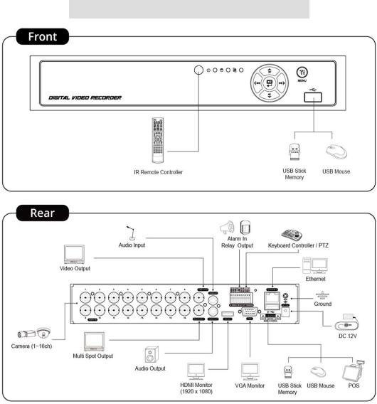
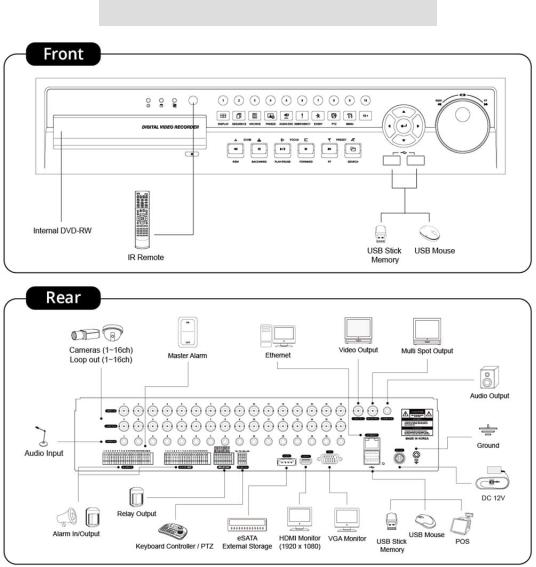
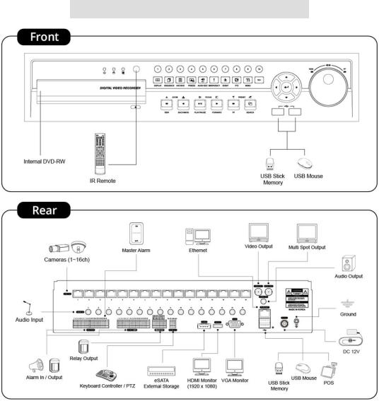
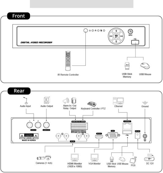
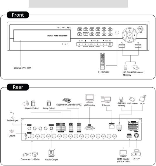
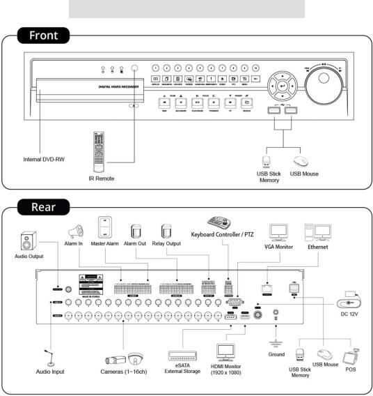
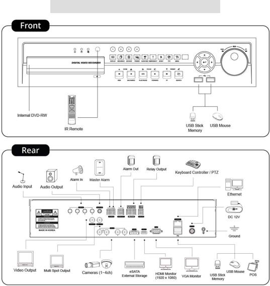
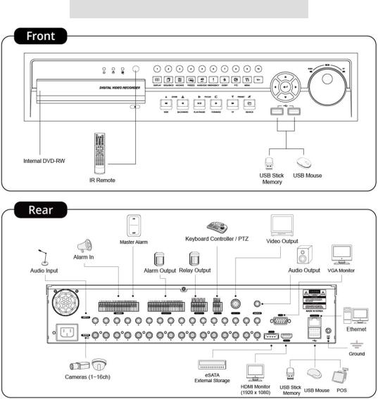
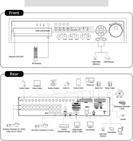
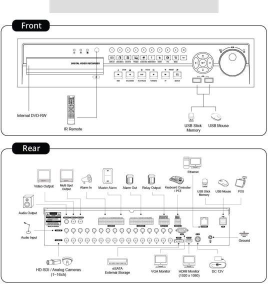
1.3 System Connection Diagram
S Type – 4 / 8 channel Series DVR
11
A Type – 4 / 8 / 16 channel Series DVR
12
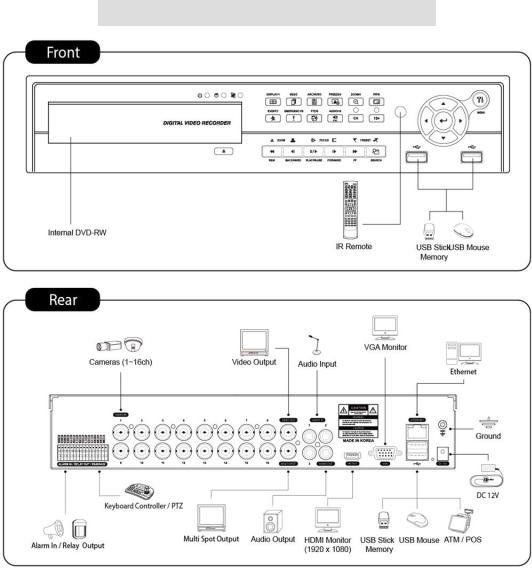
B Type – 4 / 8 / 16 channel Series DVR
13
C Type – 4 / 8 / 16 channel Series DVR
14
D Type – 4 / 8 / 16 channel Series DVR
15
E Type – 4 channel Series HD-SDI DVR
16
E Type – 8 / 16 channel Series HD-SDI DVR
17
F Type – 4 / 8 / 16 channel Series HD-SDI DVR
18
G Type – 4 channel Series HD-SDI DVR
19
G Type – 8 / 16 channel Series HD-SDI DVR
20
H Type – 4 channel Series HD-SDI DVR
21
I Type – 4 + 4 / 4 + 12 channel Series Hybrid DVR
22
J Type – 8 / 16 channel Series True Hybrid DVR
23

2. Installation
2.1 Hard disk and DVD-RW Installation
2.1.1SATA Port
When installing HDDs, make sure to connect from SATA 1 Port.
S and E (4CH) Type
-Main board of this DVR has one SATA port: it is indicated as SATA 1.
A Type
-Main board of this DVR has two SATA port: it is indicated as SATA 1 and 2.
B and E (8, 16CH) Type
-Main board of this DVR has three SATA port: it is indicated as SATA 1, 2 and 3.
-Please mount DVD-RW at the SATA 3 port.
C, D, F, G, H, I and J Type
-Main board of this DVR has five SATA ports: they are indicated as SATA 1, 2, 3, 4 and SATA 5.
-Please mount DVD-RW at the SATA 5 port.
Up to five SATA devices (HDD and DVD-RW) are able to be connected to the SATA ports in serial; however the devices must be connected onto correct SATA port.
Refer to the table below to mount HDDs and DVD-RW.
S and E (4CH) Type
|
Storage |
SATA 1 Port |
|
4 / 8 CH DVR |
HDD |
||
|
|||
|
1 |
HDD |
|
|
|
|
A Type
|
Storage |
|
SATA 1, 2 Port |
|
4 / 8 / 16 CH DVR |
HDD |
1 |
|
2 |
1 |
HDD |
|
--- |
|
|
|
|||
|
|
|
|
|
|
2 |
HDD |
|
HDD |
|
|
|
|
|
B and E (8, 16CH) Type
|
Storage |
|
|
|
|
SATA 1, 2, 3 Port |
|
|
|
HDD |
|
|
DVD- |
RW |
1 |
2 |
3 |
4 / 8 / 16 CH DVR |
1 |
|
1 |
|
|
HDD |
--- |
DVD-RW |
|
2 |
|
1 |
|
|
HDD |
HDD |
DVD-RW |
|
|
|
|
|
|
|
|
|
|
2 |
|
0 |
|
|
HDD |
HDD |
--- |
|
|
|
|
|
|
|
|
|
C, D, F, G, H, I and J (8, 16CH) Type
|
Storage |
|
|
|
SATA 1, 2, 3, 4, 5 Port |
|
|
|||
|
HDD |
|
DVD- |
RW |
1 |
2 |
3 |
|
4 |
5 |
|
1 |
|
1 |
|
HDD |
--- |
--- |
|
--- |
DVD-RW |
4 / 8 / 16 CH DVR |
|
|
|
|
|
|
|
|
|
|
2 |
|
1 |
|
HDD |
HDD |
--- |
|
--- |
DVD-RW |
|
|
3 |
|
1 |
|
HDD |
HDD |
HDD |
|
--- |
DVD-RW |
|
|
|
|
|
|
|
|
|
|
|
|
4 |
|
1 |
|
HDD |
HDD |
HDD |
|
HDD |
DVD-RW |
|
|
|
|
|
|
|
|
|
|
|
|
4 |
|
0 |
|
HDD |
HDD |
HDD |
|
HDD |
--- |
|
|
|
|
|
|
|
|
|
|
|
24
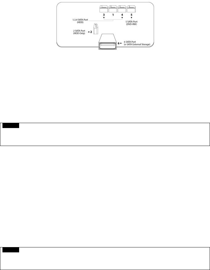
2.1.2 Internal SATA Storage
C, D, F, G, H, I and J Type DVR have 5 internal SATA Ports.
1-4 SATA Port: It is designed to mount HDD. Connect from SATA 1 port when installing HDDs.
5 SATA Port: Please mount a DVD-RW.
Only one DVD-RW can be installed among the SATA Ports.
2.1.3 e-SATA External Storage (C, F, G, H, I and J Type)
These series DVRs have one external SATA Port; the picture above shows external SATA 6 Port.
6 SATA Port: It is designed to mount up to 4HDDs per external SATA Port.
2.1.4 HDD Installation
Securely mount a hard disk using bracket and screws provided.
Please do not use any different hard disk cables (data cable and power supply cable) other than provided.
Otherwise, it may cause damage to the hard disk.
CAUTION
INSTALL DVD-RW OR/AND HARD DISK AFTER DVR POWER OFF. OTHERWISE, IT MAY CAUSE PERMANENT DAMAGE TO THE HARD DISK. TO TURN OFF DVR, PLEASE USE SHUTDOWN KEY ON SYSTEM MUNU BAR LOCATED ON THE RIGHT MARGIN. AND THEN UNPLUG THE POWER CABLE FROM DVR.
2.1.5HDD Capacity
Each model has different HDD capacity.
Below table shows the maximum HDD capacity for each model.
Type |
S, E (4CH) |
A~B |
C~D |
E (8, 16CH) |
F~J |
|
|
|
|
|
|
Capacity |
3TB |
6TB |
12TB |
6TB |
12TB |
|
|
|
|
|
|
2.1.6 DVD-RW Installation
Securely mount DVD-RW using bracket and screws provided.
Please do not use any different DVD-RW cables (data cable and power supply cable) other than provided.
Otherwise, it may cause damage to the DVD-RW.
Only one DVD-RW can be used. Mount it at the SATA 3 port (B, and E (8, 16CH)) and SATA 5 port (C, D, F, G, H, I and J Type).
CAUTION
NSTALL DVD-RW OR/AND HARD DISK AFTER DVR POWER OFF. OTHERWISE, IT MAY CAUSE PERMANENT DAMAGE TO THE HARD DISK. TO TURN OFF DVR, PLEASE USE SHUTDOWN KEY ON SYSTEM MUNU BAR LOCATED ON THE RIGHT MARGIN. AND THEN UNPLUG THE POWER CABLE FROM DVR. ALSO, WAIT FOR 5 SECONDS BEFORE PLUGGING IN POWER SUPPLY AGAIN.
25

2.2Connector Wiring
2.2.1 Video-In/Loop Out Connections
S, A, B, C and D Type
Connect Analog camera to ‘VIDEO IN’.
If a user wishes to link a camera input to another device, use ‘LOOP OUT’. (C and I Type).
Assure the ‘VIDEO IN’ (top connector) and ‘LOOP OUT’ (bottom one) connections are connected properly, not opposite way.
E, F, G and H Type
Connect HD-SDI cameras to ‘HD-SDI IN’ from channel 1 to 16.
I Type
Connect HD-SDI cameras to ‘HD-SDI IN’ from channel 1 to 4.
Connect Analog cameras to ‘VIDEO IN’ from channel 5 to 16.
J Type (True Hybrid)
Connect HD-SDI or Analog cameras to ‘any’ from channel 1 to 16.
NOTE
Only C and I Type model supports LOOP OUT connection.
NOTE
Please reboot the DVR, when switch from HD-SDI to Analog or Analog to HD-SDI (J type only)
2.2.2 HD-SDI Input Signal detection (E, F, G, H, I and J Type)
These types of DVRs automatically detect the video signals of 720P 24, 720P 25, 720P 30, 720P 50, 720P 60, 1080i 50, 1080i 60, 1080P 24, 1080P 25, 1080P 30, 1080P 50, 1080P 60 (Auto Detection) when the system starts.
720P and 1080P HD-SDI inputs can be used simultaneously with no restriction.
NOTE
1080i input cannot be used simultaneously with 720P and/or 1080P and does not support digital zoom in live mode.
(E (8, 16CH) and F (8, 16CH) Type)
2.2.3 Monitor Connections (Video Out, VGA and Multi Spot)
Video Out (S, A, B, C, D, G, H, I and J Type Only)
-Use with the CCTV monitor.
-Connect BNC cable between CCTV monitor and ‘VIDEO OUT’ of the DVR.
VGA
-Use with the computer monitor.
-Connect VGA cable between computer monitor and ‘VGA’ of the DVR
Spot (S Type Only)
-This function supports one Channel Display on Spot Monitor
-Connect BNC cable between spot monitor and spot port of rear panel.
Multi Spot (A, B, C, D, G (4 CH) and J Type Only)
-This function supports Multi-Channel Display on Spot Monitor
-Connect BNC cable between spot monitor and multi spot port of rear panel.
CAUTION
BLACK SCREEN WILL DISPLAY IF THE MONITOR DOES NOT SUPPORT THE SELECTED RESOLUTION. IN ORDER TO CHANGE THE RESOLUTION PLEASE PRESS “REW>FF>BACKWARD>FORWARD” IN SERIES USING FRONT BUTTON OR REMOTE CONTROLLER THEN THE RESOLUTION WILL BE CHANGED TO ‘1024 X 768’.
26

2.2.4HDMI connections
Connect HDMI cable to HD out port of rear panel and HDMI port of HD output device.
Please Click ( ) SETUP> DEVICE > DISPLAY > General and the following screen will display.
Click the box below to select resolution.
-A user can select the resolution among ‘1920x1080 (60Hz)’, ‘1920x1080 (50Hz)’, ‘1280x720 (60Hz)’, ‘1280x720 (50Hz)’ and ‘1024x768’.
-If the resolution is changed then the DVR may restart automatically.
-The default setting of DVR is ‘1920 x 1080 (60Hz)’.
Click Video Signal box to select signal format.
-A user can select the signal output among ‘NTSC’, ‘PAL’ and ‘AUTO’.
-The default setting of DVR is ‘AUTO’
CAUTION
HDMI CONNECTION MAY NOT BE COMPATIBLE WITH CERTAIN OUTPUT DEVICE.
VIDEO NOISE MAY OCCUR DEPENDING ON THE TYPE OF HDMI CABLE USED. MAKE SURE TO USE AN HDMI-CERTIFIED CABLE.
CAUTION
BLACK SCREEN WILL DISPLAY IF THE MONITOR DOES NOT SUPPORT THE SELECTED RESOLUTION. IN ORDER TO CHANGE THE RESOLUTION PLEASE PRESS “REW>FF>BACKWARD>FORWARD” IN SERIES USING FRONT BUTTON OR REMOTE CONTROLLER THEN THE RESOLUTION WILL BE CHANGED TO ‘1024 X 768’.
2.2.5 Audio Connections
Connect an audio device to ‘AUDIO IN’ and a speaker system to ‘AUDIO OUT’. Please use a speaker system with volume adjustable.
2.2.6 TCP/IP (Ethernet) Connections
Connect to ‘ETHERNET’ connector with the LAN cable.
When connect to Internet, use an ordinary LAN cable (Non-cross cable). However, when connect directly to a PC, please use only ‘Crossover cable’.
2.2.7 Alarm Connections (TTL)
Connect Alarm Input (Sensor) to ‘AI 1~AI 4 (or AI 16)’ connectors and connect Sensor Common to ‘G’ connector.
Connect Alarm Output (buzzer, siren, etc.) to ‘AO 1~AO 4 (or AO 16)’ connectors and connect Common to ‘G’ connector. (Except A and B type)
27

2.2.8 Master Alarm(C, D, F, G, H, I and J Type)
Alarm In sensor will be deactivated if Master Alarm is on.
Connect Master Alarm In to ‘M’ connectors.
2.2.9Alarm Connections [Relay (Dry Contact)] (Except S Type)
Connect Alarm Output (buzzer, siren, etc.) to ‘NO and/or NC’ connectors, Power to ‘COM’ connector and Ground to ‘GND’ connector.
2.2.10RS-485/42 2 Connections
PTZ Camera and Keyboard controller connector.
Please use TX+, TX-, RX+ and RXterminals accordingly.
2.2.11 RS-485 Over Coax Connection (S, A, B, C, I and J Type)
PTZ Camera Connector
Please connect Coax to ‘Video In’ and select any Protocol in Camera/PTZ setup.
NOTE
PTZ Camera must support RS-485 over Coax function in order to use this feature.
NOTE
When selecting Protocol, a user can choose any protocol from the Protocol list other than ‘NONE’. If ‘NONE’ is selected then RS-485 over Coax will not work.
2.2.12USB Connections
There are up to four identical USB ports in front and in rear. It is possible to connect a USB memory stick to archive data or a mouse to control the device.
2.2.13Grounding (Earthing)
Connection of ground wire is highly recommended to protect the DVR from external electric shock, such as lightening, electrical surge.
2.2.14 Factory Reset Switch
Reset the switch to restore all setup values to factory default. It also deletes System Log File.
The switch is located in a pin hole of the back panel.
Using a paper clip, press and hold the reset switch for 2-3 seconds and release until popup message will display.
2.2.15 Power Supply connections
S Type: Plug the power supply adapter (DC 12V, 3A, included) to ’DC12V’ connector and plug another side to power source. Adapter input voltage is a free volt (100 VAC ~ 240 VAC). Please do not use any different power supply adapter because it may cause the DVR to malfunction.
A, B and E (4CH) Type: Plug the power supply adapter (DC 12V, 5A, included) to ’DC12V’ connector and plug another side to power source. Adapter input voltage is a free volt (100 VAC ~ 240 VAC). Please do not use any different power supply adapter because it may cause the DVR to malfunction.
C, D, E (8, 16CH), F, G (4CH) H, I and J Type: Plug the power supply adapter (DC 12V, 6.67A, included) to ’DC12V’ connector and plug another side to power source. Adapter input voltage is a free volt (100 VAC ~ 240 VAC). Please do not use any different power supply adapter because it may cause the DVR to malfunction.
G (8 / 16CH) Type: Plug the power source. Products input voltage is a free volt (100 VAC ~ 240 VAC).
Please do not use any different power supply adapter because it may cause the DVR to malfunction.
28
2.2.16Connections Guideline
Video out Connector: If only the monitor is connected to VIDEO OUT connector, please set the impedance switch on the rear side of the monitor to 75 ohms to prevent abnormally bright or collapsed images. If wish to connect another device (e.g., a recorder) to the back of the monitor, please set the impedance switch on the rear side of the monitor to HIGH Z (High Impedance) and set the last device to 75 ohms.
Alarm Input Connector: Do not input any type of voltage to the AI 1~AI4 (AI 16) connectors.
29
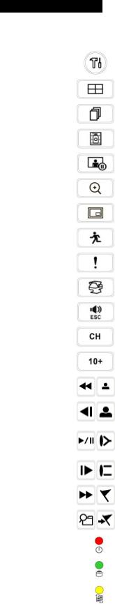
3. Input Device and Screen Icons
3.1 Key and LEDs
B and E (8, 16CH) Type
KEYS |
PTZ KEY |
Operating mode |
Setup mode |
▲, ▼, ◄, ► |
|
• Control Pan/Tilt rotation of up/down/left/right in PTZ mode |
•Up/Down/Left/Right on |
|
screen cursor control |
||
|
|
|
|
|
|
|
|
MENU |
|
• Enter the Main Menu (Setup mode) |
|
|
|
|
|
DISPLAY |
|
• Select 1/4/8/9/10/16 channel display. |
|
|
|
|
|
SEQUENCE |
|
• Channel sequence mode on/off (Main Monitor) |
|
|
|
|
|
ARCHIVE |
|
• Copy video data into the external storage device |
|
|
|
|
|
FREEZE |
|
• Screen freeze mode on/off |
|
|
|
|
|
Zoom |
|
N/A |
|
|
|
|
|
PIP |
|
• Picture In Picture display on |
|
|
|
|
|
EVENT |
|
• System Log display on |
|
|
|
|
|
EMERGENCY |
|
• Emergency recording on |
|
|
|
|
|
PTZ |
|
• Pan/Tilt/Zoom control mode on/off |
|
|
|
|
|
AUDIO/ESC |
|
• Audio on/off on selected channel (Live View). |
|
|
• ESC (Menu) |
|
|
|
|
|
|
1 ~ 10 |
|
• Camera select keys : (4/8 channel DVR) |
|
|
|
|
|
11 ~ 16 |
|
• Camera select keys : (16 channel DVR) |
|
|
|
|
|
REW |
|
• Fast backward playback (changes up to x128 with each press) |
|
|
• Zoom-Out on PTZ mode |
|
|
|
|
|
|
|
|
|
|
BACKWARD |
|
• Frame backward playback |
|
|
• Zoom-In on PTZ mode |
|
|
|
|
|
|
|
|
• Viewing mode: Instant playback (playback the recorded video from the last three minutes) |
|
PLAY/PAUSE |
|
• Playback mode: 1X PLAY/PAUSE |
|
|
|
• Focus Near in PTZ mode |
|
FORWARD |
|
• Frame forward playback |
|
|
• Focus Far in PTZ mode |
|
|
|
|
|
|
FF |
|
• Fast forward playback (changes up to x128 with each press) |
|
|
• Save Preset in PTZ mode |
|
|
|
|
|
|
SEARCH |
|
• Video search mode on |
|
|
• Go to Preset in PTZ mode |
|
|
|
|
|
|
Power LED |
|
• Light off: DVR off |
|
(Red) |
|
• Light on: DVR on |
|
|
|
|
|
HDD LED |
|
• Light off: Standby Reading/Writing |
|
(Green) |
|
• Blink : DATA Reading/Writing |
|
Network LED |
|
• Light off: No Devices are connecting to DVR through network (No User access) |
|
(Yellow) |
|
• Light On: Devices are Connecting to DVR through network (User access) |
|
30
 Loading...