


 Loading...

Thank you for purchasing the IP camera tester. Please read the manual before using the IP camera tester and use properly.
For using the IP camera tester safely, please first read the Safety Information carefully in the manual.
The manual should be kept well in case of reference.
Keep the S/N label for after-sale service within warranty period. Product without S/N label will be charged for repair service.
If there is any question or problem while using the IP camera tester, or damages occurred on the product, please contact our technical Department.
|
Content |
|
1 .Safety information ............................................................................................................................... |
1 |
|
2. IP Camera Tester Introduction ............................................................................................................. |
2 |
|
2.1 General |
...................................................................................................................................... |
2 |
2.2 Packing .................................................................................................................................list |
2 |
|
2.3 Function ......................................................................................................................interface |
3 |
|
3. Operation............................................................................................................................................. |
|
6 |
3.1 Installing ..................................................................................................................the Battery |
6 |
|
3.2 Instrument ...............................................................................................................connection |
6 |
|
3.2.1 IP ......................................................................................................camera connection |
6 |
|
3.2.2 Analog ..............................................................................................camera connection |
7 |
|
3.2.3 HD ........................................................................................Coaxial camera connection |
7 |
|
3.3 OSD menu .................................................................................................................................. |
8 |
|
3.3.1 Lite ........................................................................................................................mode |
8 |
|
3.3.2 Drop ..........................................................................................................-down Menu |
10 |
|
3.3.3 Screen ..............................................................................................................capture |
11 |
|
3.3.4 TesterPlay...................................................................................................................... |
11 |
|
3.3.5 ................................................................................................................. |
Rapid video |
12 |
3.3.6 IP ...................................................................................................................discovery |
14 |
|
3.3.7 Rapid ...........................................................................................................ONVIF test |
15 |
|
3.3.8 IP ...............................................................................................................camera test |
26 |
|
3.3.9 ..................................................................................................... |
Video monitor test |
28 |
3.3.10 ........................................................................................................ |
CVI camera test |
33 |
3.3.11 ...........................................................................................................TVI camera test |
39 |
|
3.3.12 .........................................................................................................AHD camera test |
40 |
|
3.3.13 ...............................................................................................................Network tool |
42 |
|
1 IP .............................................................................................................address scan |
42 |
|
2 PING Test...................................................................................................................... |
42 |
3 Network test (Ethernet bandwidth test) ...................................................................... |
43 |
4 Port Flashing................................................................................................................. |
46 |
5 DHCP server ................................................................................................................. |
47 |
6 Trace route................................................................................................................... |
47 |
7 Link monitor ................................................................................................................. |
48 |
3.3.14 Rapid IP Discovery ....................................................................................................... |
49 |
3.3.15 PoE power / DC12V 3A power output ......................................................................... |
49 |
3.3.16 Audio Record............................................................................................................... |
50 |
3.3.17 Data monitor ............................................................................................................... |
50 |
3.3.18 Audio player ................................................................................................................ |
51 |
3.3.19 Media Player ............................................................................................................... |
51 |
3.3.20 RTSP Player.................................................................................................................. |
52 |
3.3.21 Hik test tool ................................................................................................................. |
53 |
3.3.22 Dahua test tool............................................................................................................ |
55 |
3.3.23 Update ........................................................................................................................ |
57 |
3.3.24 Office........................................................................................................................... |
58 |
3.3.25 LED Flashlight .............................................................................................................. |
59 |
3.3.26 Browser ....................................................................................................................... |
59 |
3.3.27 Notepad: ..................................................................................................................... |
60 |
3.3.28 System Setting............................................................................................................. |
61 |
3.3.29 File explorer ................................................................................................................ |
65 |
3.3.30 Theme ......................................................................................................................... |
66 |
3. 4 Audio test................................................................................................................................ |
68 |
3.5 PoE power output .................................................................................................................... |
69 |
3.6 DC12V 3A power output .......................................................................................................... |
69 |
4. Specifications ..................................................................................................................................... |
71 |
4.1 General Specifications.............................................................................................................. |
71 |
1 .Safety information
The tester is intended to use in compliance with the local rules of the electrical usage and avoid operating in areas which are inapplicable for the use of electrics such as hospital, gas station etc.
To prevent functional decline or failure, the product should not be sprinkled or damped.
The exposed part of the tester should not be touched by the dust and liquid.
During transportation and use, it is highly recommended to avoid violent collisions and vibrations which could lead to damaging components and causing failure.
Don’t leave the tester alone while charging and recharging. If the battery is found severely hot, the tester should be powered off from the electric source at once. The tester should not be charged over 8 hours.
Don’t use the tester in high humidity. If the tester is wet, power off immediately and move away other connected cables.
The tester should not be operated around flammable gas.
Do not disassemble the instrument since no component inside can be repaired by the user. If the disassembly is necessary indeed, please contact our company.
The instrument should not be used in an area with strong electromagnetic interference.
Don’t touch the tester with wet hands or objects.
Don’t use detergent to clean and it is suggested to use a dry cloth to clean. If the dirt is not easy to remove, the soft cloth with water or neutral detergent can be used. But the cloth should be tweaked sufficiently.
Page.1.
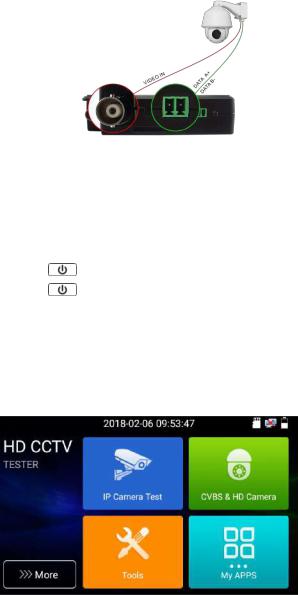
2. IP Camera Tester Introduction
2.1 General
The 4 inch IPS touch screen IP camera monitor is designed for maintenance and installation of IP cameras, analog cameras, TVI, CVI AHD cameras, as well as testing 4K H.264 /4K H.265 camera by mainstream, The 800x480 resolution enables it to display network HD cameras and analog cameras in high resolution. The unit supports many ONVIF PTZ and analog PTZ control. The combination of touch screen and key buttons make the IP camera tester very userfriendly.
The tester is also a great tool for Ethernet network testing. Other functions include providing 24W PoE power to your camera, PING and IP address searching, LED Flashlight, DC 12V 3A power output and much more. Its portability, user-friendly design and many other functions make the IP tester an essential tool for all installers or technicians.
2.2 Packing list
1). Tester
2). Adaptor DC12V 1A
3) Polymer lithium ion battery (7.4V DC 2400mAh)
4). BNC cable
5). RS485 cable
6). Output Power cable
7). Audio cable
8 wrist belt
9 Tool bag
Page.2.

2.3 Function interface
The charge indicator: it lights red while the battery is being charged. As the
1
charging is complete, the indicator turns off automatically
The RS485 data transmission indicator: it lights red while the data is being
2
transmitted
Page.3.

Top interface
Left interface
Right interface
Page.4.

Bottom interface
3Video image signal input BNC interface / AHD,CVI and TVI input (BNC interface)
4Power battery switch
Return/Close: Return or cancel while setting parameters of the menu, close or decrease
5
the aperture
6Confirm key (Long press it to capture screen interface)
7Function switching key
Press more than 2 seconds, turn on or off the device, short press to turn on or off the
8
menu display
9RS485 Interface: RS485communication for the PTZ
10LED lamp
11DC12V3A power output, for provisional DC power supply
12PoE power supply output or LAN test port (Use to test PoE or non-PoE IP camera)
13DC12V 1A charging interface
14Audio input
15Micro SD card moveable, supports up to 32GB
Page.5.
3.Operation
3.1Installing the Battery
The tester has built-in lithium ion polymer rechargeable battery. The battery cable inside the battery cabin should be disconnected for safety during transportation!
Prior to the use of the instrument, the battery cables inside the battery cabin should be well
connected. |
|
Pressing the key |
continuously can power on or off the tester. |
 Notice: Please use the original adaptor and connected cable of the device!
 When the battery icon is full or the charge indicator turns off automatically, indicates the battery charging is completed
 Notice: When the Charge Indicator
  turns off, the battery is approximately 90%
charged. The charging time can be extended for about 1 hour and the charging time within 12 hours will not damage the battery.
 Notice: Press the key
  several seconds to restore the default settings when the
instrument is functioning abnormally.
3.2 Instrument connection
3.2.1 IP camera connection
Power an IP camera with an independent power supply, then connect the IP camera to the IPC tester’s
LAN port, if the link indicator of the tester’s LAN port is green and the data indicator flickers, it means the IP camera and the IPC tester are communicating. If the two indicators don’t flicker, check if the IP camera is powered on or if the network cable is not functioning properly.
Page.6.

Note: If the IP camera requires PoE power, then connect the IP camera to the IP tester’s LAN port. The tester will supply PoE Power for the IP camera. Click on the icon labeled POE to turn the PoE Power off or on.
3.2.2 Analog camera connection
(1)Connect the camera's video output to the IP tester’s VIDEO IN. The image will display on the tester after pushing the PTZ icon
(2)Connect the camera or the speed dome RS485 controller cable to the tester RS485 interface (Note positive and negative connection of the cable).
3.2.3 HD Coaxial camera connection
* CVI, TVI, AHD camera are classified as HD coaxial cameras. Hereby the following instruction of how
Page.7.
to connect CVI camera to the tester is also applied to CVI, TVI and AHD camera.
(1)Connect the CVI camera's video output to the IP tester’s “Video IN” interface, the image will display on the tester. The tester only come with CVI input interface. There is no CVI output interface.
(2)Connect the CVI camera or the speed dome RS485 controller cable to the tester RS485 interface.
3.3 OSD menu
|
Press the key |
2 seconds to turn on |
|
Press the key |
2 seconds to turn off |
Short press the key  to enter sleep mode, press it again to test if tester is working abnormally and cannot be turned off , Press the key
  several seconds to turn off, the
tester will reset
3.3.1 Lite mode
Lite mode: You can easily find corresponding apps
Page.8.
In Lite mode, click the finger icon in the lower right corner till
yellow, long press the icon to move the function icon to other items. Do not click the finger icon and long press the application icon, then you can move the icon in the folder.
Click SD card, install or remove SD card.
Page.9.

3.3.2 Drop-down Menu
Press and slide on the top right corner twice to open the shortcut menu. The shortcut menu includes POE power output, IP settings, HDMI IN, CVBS, TV OUT, LAN, settings etc.
CVBS: Click icon “CVBS” to open CVBS application.
LAN: Display network port or WIFI connection real-time upload and download speeds and other network parameters.
Settings: Enter settings interface.
IP: Enter IP Settings interface.
Page.10.

POE power output: Turn on or off the tester “PoE power “app.
3.3.3 Screen capture
Long press the key “enter”, then you can screen capture the interface and save it at any time.
You can go to file management to view “file management –sdcard- Pictures—Screenshots”.
3.3.4 TesterPlay
Mobile screen projection (Only for android version)
The meter can create a WIFI hotspot, connect mobile phone to the tester’s WIFI hotspot, or connect the tester and mobile phone to the same Wi-fi network. Tap icon “ ”, then select the
“TesterPlay” app to enter, click “Start” button to generate two-dimensional code, Please use mobile phone to scan , then download and install the client software, you can view the screen real-time projection.
Page.11.
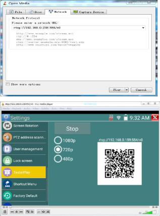
PC screen projection
Install VLC player in the PC, turn on the VLC player "Media - Open Network Streaming", and input the RTSP address on the top instrument two-dimensional code, click "play" to view the screen real-time projection.
3.3.5 Rapid video
Page.12.

Press |
enter function, One key to detect all network cameras and auto play the images. |
Auto log in and display camera image. For detailed operation refer to ONVIF function
After exit ONVIF app, Click Refresh to search ip address.
Page.13.
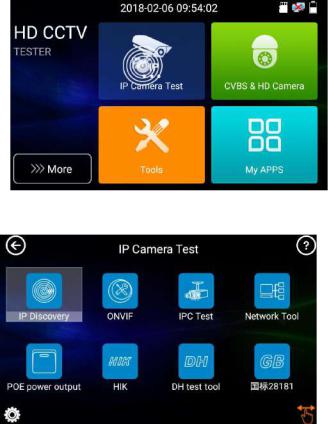
3.3.6IP discovery
Press IP discovery |
, tester will auto-scan the whole network segment IP, as well as |
auto-modify the tester’s IP to the same network segment with the scanned camera's IP.
The meter will Auto-search for a connected a network segment, and will auto-add the IP of a different network segments. To detect unactivated Dahua and Hikvision cameras, click “OK”, go to Dahua and Hikvision Test Tool.
Local IP Tester’s IP address, Tester can auto-modify the tester’s IP to the same network segment with the scanned camera's IP
Discovery IP Connected tester equipment’s IP address. If the camera connected to the tester directly, tester will display the camera’s IP address, if tester connects to Local Area Network, it displays the current IP address.
Start: PING function, Click "Start", can PING camera’s IP
Rapid ONVIF: Rapid ONVIF Quick link
IPC TEST: IPC TEST Quick link
Applicability Using IP discovery app, you don’t need to know the first two digits of camera’s IP address, it can auto-scan the whole network segment IP, and auto-modify tester’s IP address, greatly improved engineering efficiency.
Page.14.
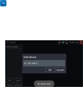
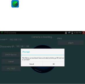
3.3.7 Rapid ONVIF test
Rapid ONVIF can display 4K H.265/H.264 camera image by tester mainstream, one key to activate Hikvision camera
Press enter ONVIF function, the meter will auto scan all ONVIF cameras on different network
segments. It will list camera names and IP addresses on the Left side of the screen. Tester can auto log into camera and display camera image. Factory Settings use admin password to auto login, if you modified the password, then use the modified password to login.
If you select ONVIF Rapid mode, the meter will automatically scan different network segments for ONVIF cameras. It will list the camera name and IP address on the Device List. Tester can auto login camera and display camera image.
Click the button “Refresh”, tester will rescan for ONVIF cameras. Click the newly displayed ONVIF camera on the “Device List”. The tester will show the IP camera’s relative information and settings.
Activate HIKVISION Camera: When connected to unactivated HIKVISION Camera, tester can auto recognize, and prompt "The camera is not active, you need to activate it", click "OK" to activate. Enter a new password for the camera.
Page.15.
When comes out “activate success” prompt, click login to display camera image.
Pop-up settings menu when click the “ONVIF setting ” icon in the upper left corner
Page.16.

Auto Login: After open this function, tester can auto login camera and display camera image (The login password is the same with last time, the first time using password is the default password "admin")
Video transmission protocol: UTP and TCP protocol
Open password cracker: Cracks password of cameras
Show focusInfo:Focus Information.
View manual: Open Manual
Restore Defaults: Revert “Rapid ONVIF” to default settings
Confirm: Save the modified parameters
Click “MENU” icon to open camera setting .
While in the “Live video” menu, click “Video Menu” at the top right of the image to access the following tools: Snapshot, Record, Photo, Playback, Lens simulation, PTZ and Settings.
Page.17.
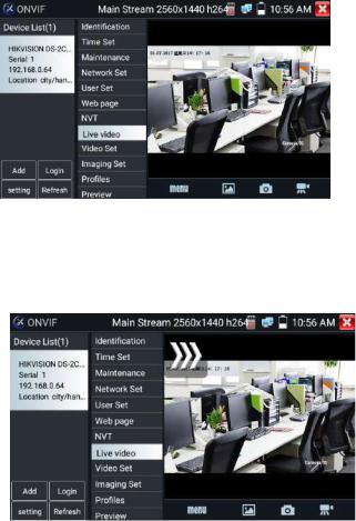
ONVIF PTZ control: Tap the image in the direction you want the PTZ camera to move. Tap the left side of the image to move left, right to go right, up to go up and down to go down. Compatible IP PTZ cameras will rotate accordingly. PTZ rotation direction is displayed on top left corner of the image.
IP camera video settings: Click “Video Set” to enter the IP camera’s encoder and resolution settings.
Make the desired changes and click “OK “to save.
Page.18.
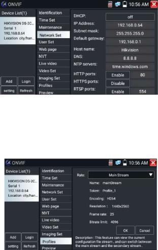
Image setting: Click “Imaging Set” to adjust image brightness, saturation, contrast, sharpness and backlight compensation mode.
Profiles: Click “profiles", can view video streaming current configuration files, as well as switch between Major stream and minor stream.
Preview pictures: Quickly preview and zoom in or out pictures, automatically and manual refresh
Identification: click “Identification” to view information of the camera.
Page.19.
Loading...