


AIVO-70A4K
USER MANUAL
AIVO-70A4K

Thank you for purchasing the IP camera tester. Please read the manual before using the IP camera
tester and use properly.
For using the IP camera tester safely, please first read the「Safety Information」carefully in the
manual.
The manual should be kept well in case of reference.
Keep the S/N label for after-sale service within warranty period. Product without S/N label will
be charged for repair service.
If there is any question or problem while using the IP camera tester, or damages occurred on the
product, please contact our technical Department.

Content
1 .Safety information ----------------------------------------------------------------------------------------------------- 1
2. IP Camera Tester Introduction --------------------------------------------------------------------------------------- 2
2.1 General ----------------------------------------------------------------------------------------------------------- 2
2.2 Packing list ------------------------------------------------------------------------------------------------------ 3
2.3 Function interface ---------------------------------------------------------------------------------------------- 4
3. Operation ---------------------------------------------------------------------------------------------------------------- 7
3.1 Installing the Battery ------------------------------------------------------------------------------------------- 7
3.2 Instrument connection ----------------------------------------------------------------------------------------- 8
3.2.1 IP camera connection --------------------------------------------------------------------------------- 8
3.2.2 Analog camera connection --------------------------------------------------------------------------- 9
3.2.3 HD Coaxial camera connection ------------------------------------------------------------------- 10
3.2.4 HDMI IN ---------------------------------------------------------------------------------------------- 11
3.3 OSD menu ----------------------------------------------------------------------------------------------------- 11
3.3.1 Lite mode & Normal mode------------------------------------------------------------------------- 11
3.3.2 Drop-down Menu ------------------------------------------------------------------------------------ 15
3.3.3 Short cut-menu --------------------------------------------------------------------------------------- 16
3.3.4 Screen capture ---------------------------------------------------------------------------------------- 17
3.3.5 TesterPlay --------------------------------------------------------------------------------------------- 17
3.3.6 Rapid video ------------------------------------------------------------------------------------------- 19
3.3.7 IP discovery ------------------------------------------------------------------------------------------- 20
3.3.8 Rapid ONVIF test ------------------------------------------------------------------------------------ 21
3.3.9 IP camera test ----------------------------------------------------------------------------------------- 36
3.3.10 HDMI IN --------------------------------------------------------------------------------------------- 38
3.3.11 Video monitor test---------------------------------------------------------------------------------- 42
3.3.12 Color-bar generator (TV OUT) ------------------------------------------------------------------ 51
3.3.13 SDI/EX-SDI Camera Test ( *Optional ) ----------------------------------------------------- 53
3.3.14 CVI camera test ( *Optional ) ----------------------------------------------------------------- 54

3.3.15 TVI camera test ( *Optional ) ------------------------------------------------------------------ 61
3.3.16 AHD camera test ( *Optional ) ---------------------------------------------------------------- 63
3.3.17 Network tool ---------------------------------------------------------------------------------------- 64
(1)IP address scan ------------------------------------------------------------------------------------- 64
(2)PING Test -------------------------------------------------------------------------------------------- 65
(3)Network test (Ethernet bandwidth test) --------------------------------------------------------- 66
(4)Port Flashing ----------------------------------------------------------------------------------------- 69
(5)DHCP server ----------------------------------------------------------------------------------------- 71
(6)Trace route ------------------------------------------------------------------------------------------- 71
(7)Link monitor ----------------------------------------------------------------------------------------- 72
3.3.18 Rapid IP Discovery -------------------------------------------------------------------------------- 73
3.3.19 PoE power / DC12V 2A and DC 5V 2A USB power output ------------------------------- 73
3.3.20 Cable Test-------------------------------------------------------------------------------------------- 75
3.3.21 RJ45 cable TDR test ------------------------------------------------------------------------------- 76
3.3.22 Cable Tracer ----------------------------------------------------------------------------------------- 79
3.3.23 TDR cable test ( *Optional ) ------------------------------------------------------------------- 80
3.3.24 PoE Voltage test ------------------------------------------------------------------------------------ 83
3.3.25 12V power input test ------------------------------------------------------------------------------- 84
3.3.26 Digital Multi-meter ( *Optional ) ------------------------------------------------------------- 85
3.3.27 Optical power meter ( *Optional ) ------------------------------------------------------------ 92
3.3.28 Visual Fault Locator ( *Optional ) ------------------------------------------------------------ 94
3.3.29 Audio Record --------------------------------------------------------------------------------------- 96
3.3.30 Data monitor ---------------------------------------------------------------------------------------- 96
3.3.31 Audio player ----------------------------------------------------------------------------------------- 97
3.3.32 Media Player ---------------------------------------------------------------------------------------- 97
3.3.33 RTSP Player ----------------------------------------------------------------------------------------- 98
3.3.34 Hik test tool------------------------------------------------------------------------------------------ 99
3.3.35 Dahua test tool ------------------------------------------------------------------------------------- 102
3.3.36 Update ----------------------------------------------------------------------------------------------- 106

3.3.37 Office ------------------------------------------------------------------------------------------------ 107
3.3.38 LED Flashlight ------------------------------------------------------------------------------------- 107
3.3.39 Browser --------------------------------------------------------------------------------------------- 108
3.3.40 Notepad --------------------------------------------------------------------------------------------- 108
3.3.41 System Setting ------------------------------------------------------------------------------------- 109
3.3.42 File explorer ---------------------------------------------------------------------------------------- 113
3.3.43 Theme ----------------------------------------------------------------------------------------------- 115
3. 4 Audio test ---------------------------------------------------------------------------------------------------- 118
3.5 HDMI output ------------------------------------------------------------------------------------------------- 118
3.6 PoE power output -------------------------------------------------------------------------------------------- 118
3.7 DC12V 2A power output ---------------------------------------------------------------------------------- 119
4. Specifications -------------------------------------------------------------------------------------------------------- 121
4.1 General Specifications -------------------------------------------------------------------------------------- 121
4.2 Multi-meter specifications --------------------------------------------------------------------------------- 124
4.3 Optical power meter specifications ---------------------------------------------------------------------- 126
4.4 Visual fault locator specifications ------------------------------------------------------------------------ 127

1 .Safety information
◆ The tester is intended to use in compliance with the local rules of the electrical usage and avoid to
apply at the places which are inapplicable for the use of electrics such as hospital, gas station etc.
◆ To prevent the functional decline or failure, the product should not be sprinkled or damped.
◆ The exposed part of the tester should not be touched by the dust and liquid.
◆ During transportation and use, it is highly recommended to avoid the violent collision and vibration
of the tester, lest damaging components and causing failure.
◆Don’t leave the tester alone while charging and recharging. If the battery is found severely hot, the
tester should be powered off from the electric source at once. The tester should not be charged over 8
hours.
◆ Don’t use the tester where the humidity is high. Once the tester is damp, power off immediately and
move away other connected cables.
◆ The tester should not be used in the environment with the flammable gas.
◆ Do not disassemble the instrument since no component inside can be repaired by the user. If the
disassembly is necessary indeed, please contact with the technician of our company.
◆ The instrument should not be used under the environment with strong electromagnetic interference.
◆ Don’t touch the tester with wet hands or waterish things.
◆ Don’t use the detergent to clean and the dry cloth is suggested to use. If the dirt is not easy to remove,
the soft cloth with water or neutral detergent can be used. But the cloth should be tweaked
sufficiently.
About Digital Multi-meter
◆ Before using, you must select the right input jack, function and range.
◆ Never exceed the protection limit values indicated in specifications for each range of measurement.
◆When the tester is linked to a measurement circuit, do not touch unused terminals.
◆Do not measure voltage if the voltage on the terminals exceeds 660V above earth ground.
◆At the manual range, when the value scale to be measured is unknown beforehand, set the range
selector at the highest position.
◆Always be careful when working with voltages above 60V DC or 40V AC, keep fingers behind the
probe barriers while measuring.
Page.1.

◆Never connect the meter with any voltage source while the function switch is in the current,
resistance, capacitance, diode, continuity, otherwise it will damage the meter.
◆Never perform capacitance measurements unless the capacitor to be measured has been discharged
fully.
◆Never measure any of resistance, capacitance, diode or continuity measurements on live circuits.
Visual laser sources
When you turn on visual laser sources, please don’t stare at it, or will damage to eyes
When not using it, please turn it off and cover the protective cap .
2. IP Camera Tester Introduction
2.1 General
The 7 inch touch screen IP camera monitor is designed for maintenance and installation of IP cameras,
analog cameras, TVI, CVI, AHD, SDI/EX-SDI cameras, as well as testing 4K H.264 /4K H.265 camera
by mainstream, The 1920x1200 resolution enables it to display network HD cameras and analog
cameras in high resolution. The unit supports many ONVIF PTZ and analog PTZ control. The
combination of touch screen and key buttons make the IP camera tester very user- friendly.
The tester is also a great tool for Ethernet network testing. It can test PoE power voltage, PING, and IP
address searching. You can use the blue cable tracer to locate individual connected cables from a bundle
of cables. Test LAN cable for proper connection termination. Other functions include providing 24W
PoE power to your camera, HDMI IN and out, CVBS loop test, testing IP and analog at the same time,
LED Flashlight, DC 12V 2A power output and much more. Its portability, user-friendly design and
many other functions make the IP tester an essential tool for all installers or technicians.
Page.2.

2.2 Packing list
1). Tester
2). Adaptor DC12V 2A
3). Network cable tester
4). Polymer lithium ion battery (7.4V DC 5000mAh)
5). BNC cable
6). RS485 cable
7). SC,ST connector(Only for optical power meter)
8). Multi-meter test leads one pair of red and black (only for the Multi-meter models)
9). Output Power cable
10). Audio cable
11). TDR alligator clamp (only for TDR models)
12). Safety cord
13). Tool bag
14). Manual
15).8GB SD card
Page.3.
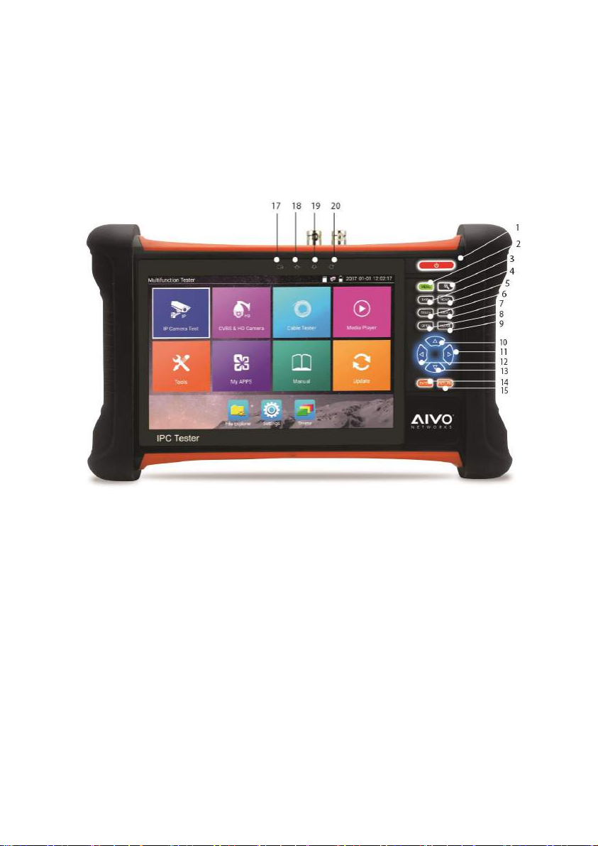
2.3 Function interface
Page.4.
1
Press more than 2 seconds, turn on or off the device,short press to turn on or off
the menu display
2 Menu key. press it to call shortcut- menu
3 4xzoom the image displays.
4 Far focus: Focus the image faraway
5 Near focus: Focus the image nearby
6 TELE: zoom in the image
7 WIDE: zoom out the image
8 Open/set, Confirm the setting of parameters, open or enlarge the aperture
9
10 Upward, set function or add parameter. Tilt the PTZ upward
11
Rightward, select the parameter whose value will be changed. Add the value of the
parameter. Pan the PTZ right
12 Leftward, select the parameter whose value will be changed
13
Downward, set function or reduce the value of the parameter. Tilt the PTZ
downward
14 Confirm key (Long press it to capture screen interface)
15 Return/Close: Return or close
16
Multimeter interface (Optional)
17
The charge indicator: it lights red while the battery is being charged. As the
charging is complete, the indicator turns off automatically
18
The RS485 data transmission indicator: it lights red while the data is being
transmitted
19 The data received indicator: it lights red while the data is being received
20 The power indicator: it lights green while the tester is powered on by the adapter
Page.5.
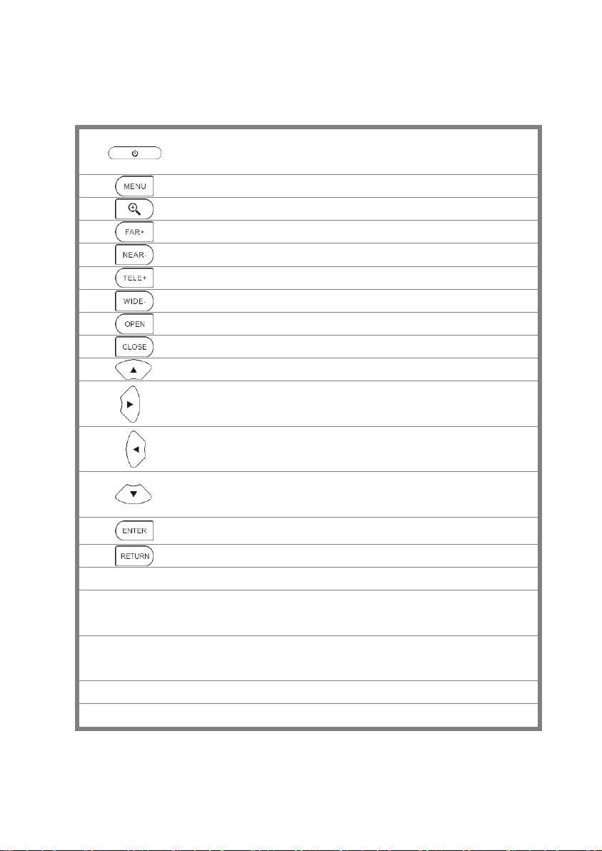
Top interface
Bottom interface
21
TDR cable test interface (Optional)
22
SDI input (BNC interface) ( Optional)
23
RS485 Interface: RS485communication for the PTZ
24
HDMI IN
25
Video signal output(BNC interface)/ cable tracer interface
26
CVBS input /AHD /TVI/CVI Coaxial interface (AHD /TVI/CVI Optional )
27
Optical power meter interface (Optional)
28
PoE power supply output or LAN test port (Use to test PoE or non-PoE IP camera)
29
PSE power sourcing equipment. Tests PoE voltage
30
DC 12V 2A power output , for provisional DC power supply
31
LED lamp
Page.6.
32
Visible red laser source emits Interface (Optional)
33
Power battery switch
34
DC 12V 2A charging interface
35
Audio input
36
Audio output and earphone interface
37
USB 5V 2A power output (used only for power, not data)
38
UTP cable port: UTP cable tester port/ Cable tracer port
39
Micro SD card moveable (comes with 8GB, supports up to 32GB)
40
HDMI output interface
3. Operation
3.1 Installing the Battery
The battery main switch at the right-bottom corner of tester bottom.
“0”: Battery power off
“1”: Battery power on
The tester has built-in lithium ion polymer rechargeable battery, the tester’s bottom power should turn
to “0”for safety during transportation (the factory default is “0”)
Using the instrument, pls switch power button to “1”, press the several seconds can turn
on/off tester. In general, user no need to turn on battery switch.if don’t use the instrument in long time,
pls turn off the switch.
Notice: Pls use the original adaptor and connected cable of the device!
When the battery icon is full or the charge indicator turns off automatically, indicate the battery
charging is completed
Notice: When the Charge Indicator turns off, the battery is approximately 90%
charged. The charging time can be extended for about 1 hour and the charging time within 12
Page.7.
hours will not damage the battery.
Notice: Press the key several seconds to restore the default settings when the
instrument works abnormally.
Multi-meter: The red and black multi-meter pen must insert the corresponding port.
Warnings: Instrument communication port is not permitted access circuit voltage over 6V,
otherwise damage the tester.
Warnings: Not allow insert multi-meter pen in the current
terminal to measure voltage.
3.2 Instrument connection
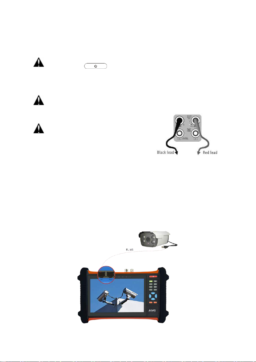
3.2.1 IP camera connection
Power an IP camera with an independent power supply, then connect the IP camera to the IPC tester’s
LAN port, if the link indicator of the tester’s LAN port is green and the data indicator flickers, it means
the IP camera and the IPC tester are communicating. If the two indicators don’t flicker, check if the IP
camera is powered on or the network cable is not functioning properly.
Page.8.

Note:1) If the IP camera requires PoE power, then connect the IP camera to the IP tester’s LAN port .
The tester will supply PoE Power for the IP camera. Click on the icon labeled POE to turn the PoE
Power off or on.
2) If use the tester’s menu to turn off the tester’s PoE power supply, the PoE switch and the power
sourcing equipment are allowed to connect to the tester’s PSE port, and the PoE power will be supplied
to the IP camera by the tester’s LAN port. On this condition, the tester cannot receive data from IP
camera, but the computer connected to the PoE switch can receive the data via the the tester.
Warning: PoE switch or PSE power sourcing equipment only can be connected to tester “PSE
IN” port, otherwise will damage the tester.
3.2.2 Analog camera connection
Page.9.

(1) ) Connect the camera's video output to the IP tester’s VIDEO IN. The image will display on the
tester after pushing the PTZ icon.
(2) CCTV IP Tester “VIDEO OUT” interface connect to the Video input of monitor and optical video
transmitter and receiver, the image display on the tester and monitor.
(3) Connect the camera or the speed dome RS485 controller cable to the tester RS485 interface (Note:
positive and negative connection of the cable).
3.2.3 HD Coaxial camera connection
* SDI/EX-SDI, CVI, TVI, AHD camera are classified as HD coaxial cameras. Hereby the following
instruction of how to connect SDI camera to the tester is also applied to CVI, TVI, and AHD camera.
(1) Connect the SDI camera's video output to the IP tester’s “SDI IN” interface, the image will display
on the tester. The tester only come with SDI input interface. There is no SDI output interface.
(2) Connect the SDI camera or the speed dome RS485 controller cable to the tester RS485 interface
(Note: positive and negative connection of the cable).
Page.10.
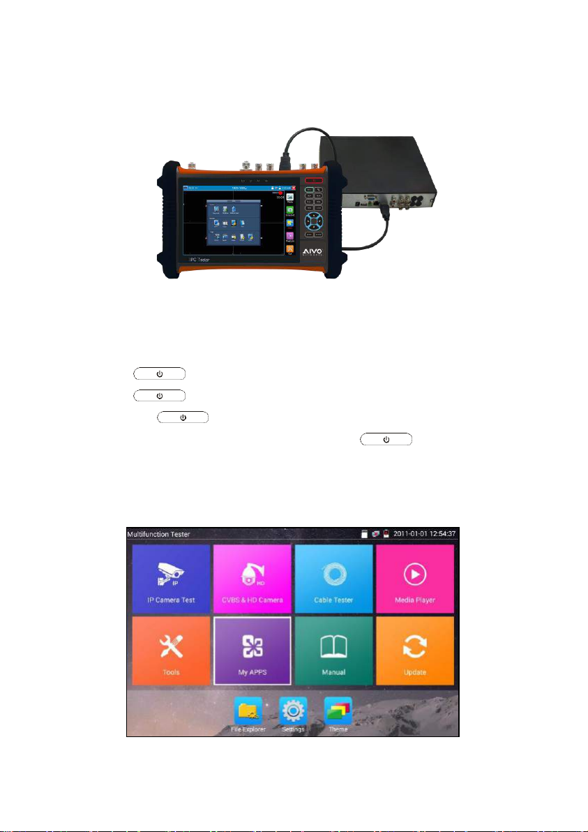
3.2.4 HDMI IN
DVR or other device’s HDMI out port connect to tester’s HDMI in port, the meter will display input
image.
3.3 OSD menu
Press the key 2 seconds to turn on
Press the key again to turn off
short press the key to enter sleep mode, press it again to test.
If tester works abnormally and cannot be turned off , Press the key several seconds to
turn off, the tester reset.
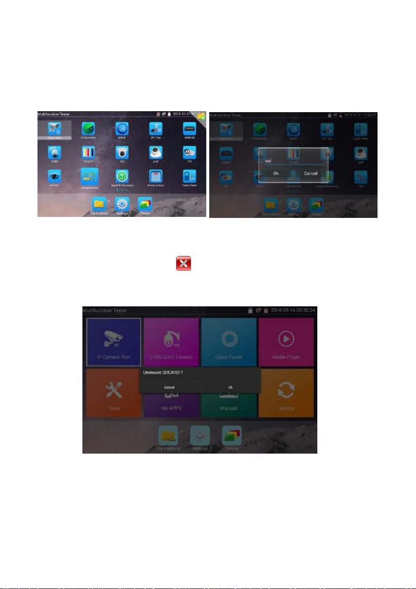
3.3.1 Lite mode & Normal mode
Lite mode: You can easy find corresponding apps
Page.11.
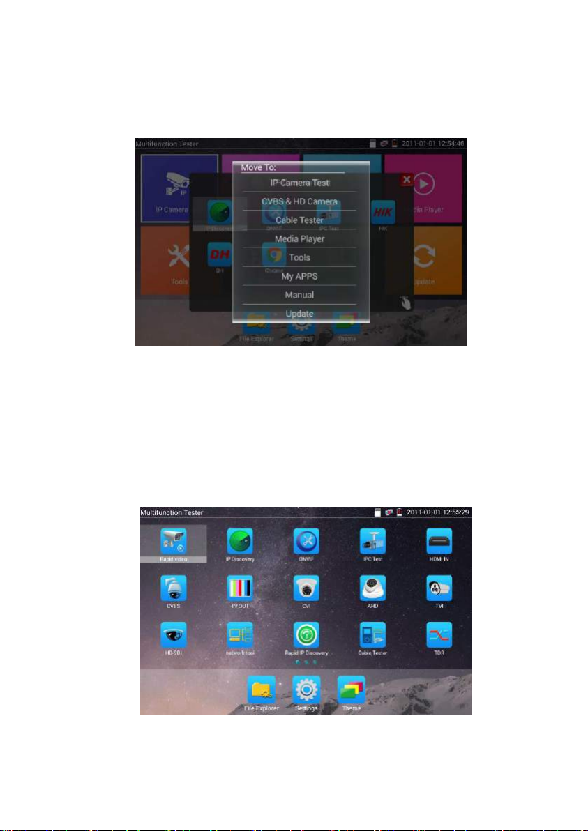
In Lite mode, Press the icon several seconds, can move the icon to other apps.
In lite mode, click the finger icon in the lower right corner to release lock icon, move icons and
change function icons sequence.
Normal mode
Tap the screen and slide left or right to change menu.
Page.12.

In normal mode, press icon several seconds, go screen management status. Change icons sequence and
move it to common tools bar.
You can move the icon to any pages, self-define the number of icons in any page. Make interface
sample and individuality.
Page.13.
Create New Folder: Drag the icon to the folder in top right corner, enter the folder name, icon will be
auto placed in the new named folder.
Press the folder several seconds, to change the folder name, you can move the icon out of folder, the
folder will be auto deleted until move out all icons.
Select Icons to enter, if quit, please click
Click SD card, install or remove SD card.
Page.14.
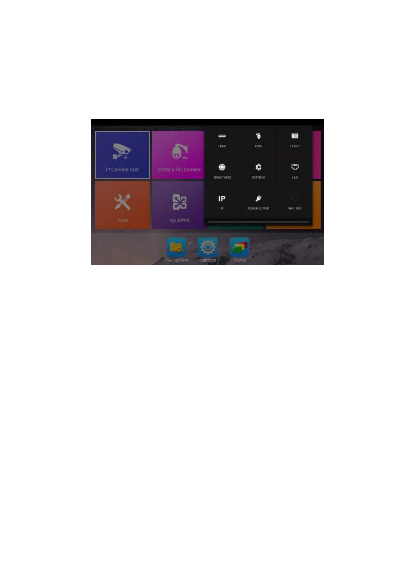
3.3.2 Drop-down Menu
Press and slide at right top right corner twice to open shortcut menu. The shortcut menu includes POE
power output, IP settings, Wi-Fi, HDMI IN, CVBS, Video OUT, LAN, Brightness, settings etc.
HDMI: Click HDMI IN to enter, in HDMI IN mode, it can converter test from analog to digital
with dual test window IP & HDMI IN or Analog & HDMI in
CVBS: Click icon “CVBS” to enter, you can test IP and analog camera at the same time
Video OUT: Click “Video OUT” to enter floating window, connecting the BNC cable to tester
and appears analog video monitor interface, it can test circuit and BNC cable whether normal.
LAN: Display network port or WIFI connection real-time upload and download speeds and
other network parameters.
Brightness: Set brightness
Settings: Enter settings interface.
IP: Enter IP Settings interface.
POE power output: Turn on or off the tester “PoE power” app
WLAN: Turn on WLAN net and displays current WLAN status.
Page.15.

3.3.3 Short cut-menu
You can call shortcut menu by press tester’s “menu” key, you can self-define shortcut menu.
Press the key“ ”, you can turn on it, and switch functions, then press to enter app, tap
other area on the screen, to exit the menu.
Short cut-menu setting, you can long press any app in the all applications list, it will auto move to
shortcut menu. If delete any app in the shortcut menu, please select a app and press several seconds, it
will be deleted.
Page.16.
3.3.4 Screen capture
Long press the key “enter”, can capture screen interface and save it in any time.
You can go file management to view “File management - SDcard - Pictures - Screenshots”.
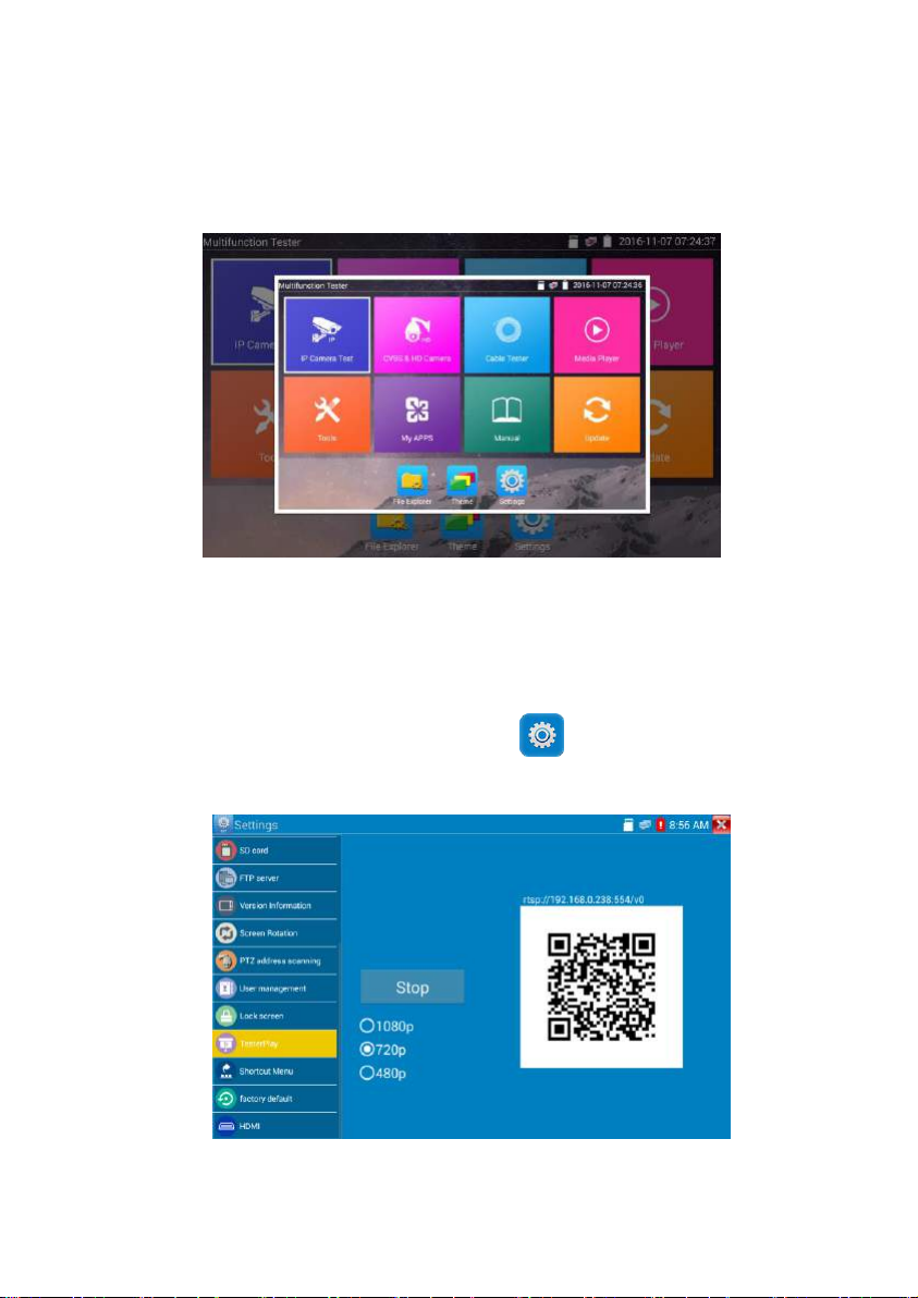
3.3.5 TesterPlay
Mobile screen projection (Only for android version)
The meter creates WIFI hotspot, connect mobile phone to the tester’s WIFI hotspot, or the tester and
mobile phone connect to the same Wi-fi network. Tap icon “ ”, then select “TesterPlay” app to
enter, click “Start” button to generates two-dimensional code, Please use mobile phone scan it, then
download and install the client software, you can view the screen real-time projection.
Page.17.
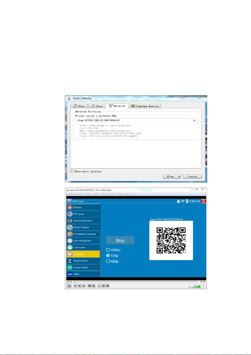
PC screen projection:
Install VLC player in the PC, turn on the VLC player "Media - Open Network Streaming", and input the
RTSP address of on the top instrument two-dimensional code, click "play" to view the screen real-time
projection. (you also can install “VLC player” in the mobile phone, tester and mobile phone display at
the same time)
Page.18.
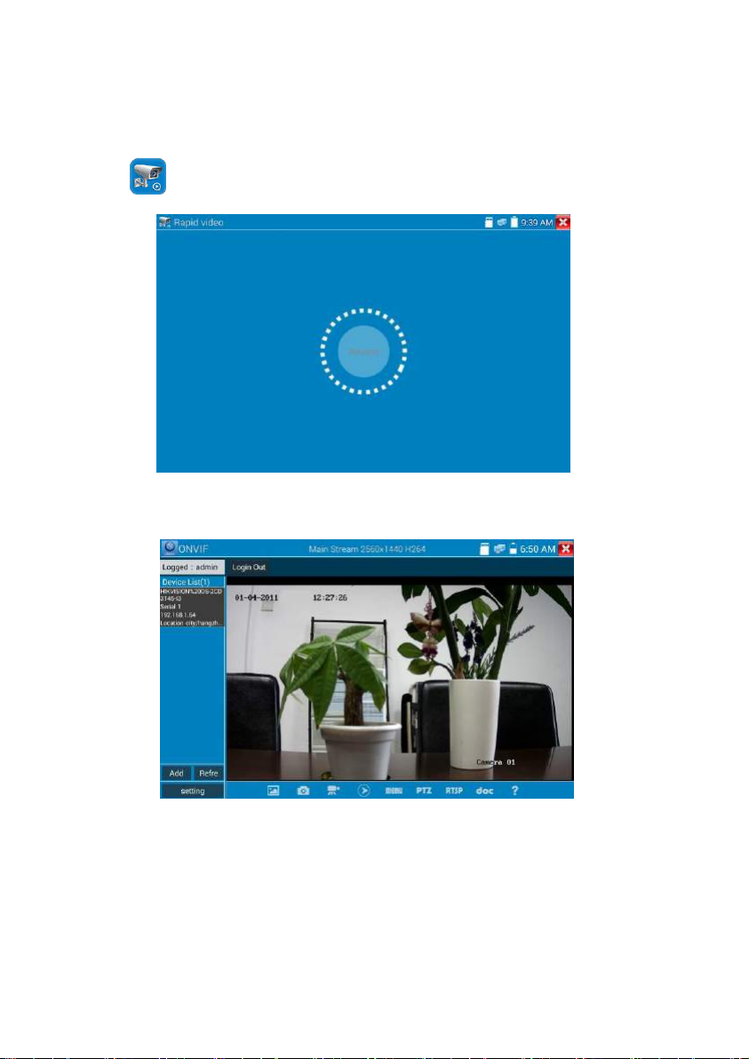
3.3.6 Rapid video
Press enter function, One key to detect all network cameras and auto play the images.
Auto log in and display camera image. Detailed operation refer to ONVIF function.
Page.19.
After exit ONVIF app, Click Refresh to search ip address.
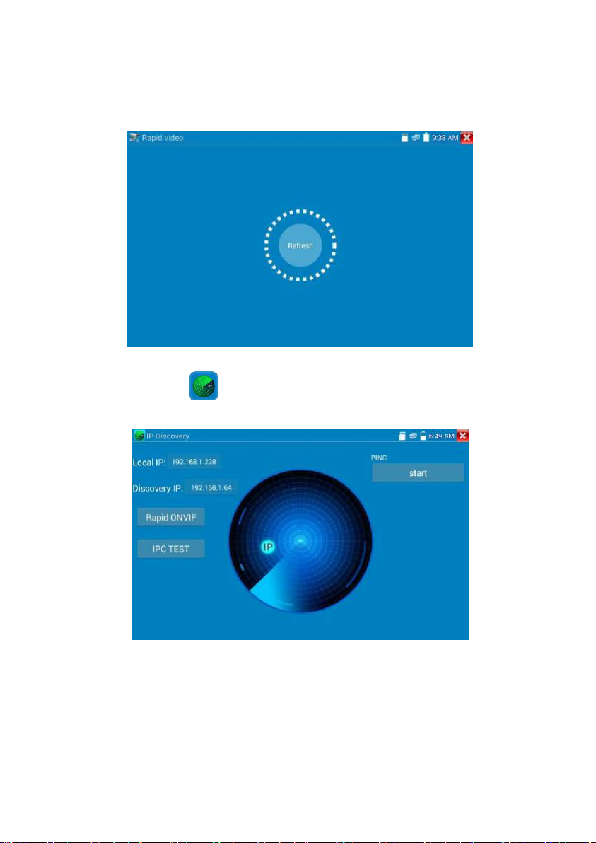
3.3.7 IP discovery
Press IP discovery ,tester auto-scan the whole network segment IP, as well as
auto-modify the tester’s IP to the same network segment with the scanned camera's IP.
Local IP: Tester’s IP address, Tester can auto-modify the tester’s IP to the same network segment with
the scanned camera's IP.
Discovery IP: Connected tester equipment’s IP address. If the camera connected to the tester directly,
tester will display the camera’s IP address, if tester connects to Local Area Network, it displays the
Page.20.
current IP address.
Temp IIP:After searching IP address, the modified tester’s IP address will not be saved, if you do not
select “Temp IP”, the tester’s IP address will auto-save after searching.
Start: PING function, Click "Start", can PING camera’s IP.
Rapid ONVIF: Rapid ONVIF Quick link
IPC TEST: IPC TEST Quick link
Applicability: Using IP discovery app,you don’t need to know the first two digits of camera’s IP
address, it can auto-scan the whole network segment IP, and auto-modify tester’s IP address, greatly
improved engineering efficiency.
3.3.8 Rapid ONVIF test
Rapid ONVIF can display 4K H.265/H.264 camera image by tester mainstream, one key to activate
Hikvision camera.
Press enter ONVIF function, the meter auto scan all ONVIF cameras in different network
segments. It lists cameras name and IP address on the Left of screen. Tester can auto login camera and
display camera image. Factory default use admin password to auto login, if you modified the password,
Page.21.
then default use the modified password to log in.
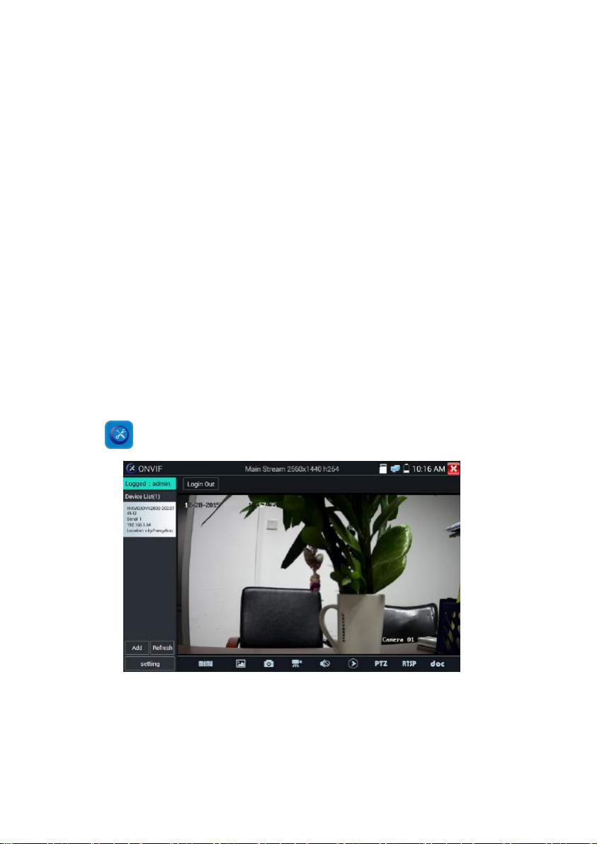
If you select ONVIF Rapid mode, the meter automatically scan different network segments for ONVIF
cameras. It lists the camera name and IP address on the Device List. Tester can auto login camera and
display camera image.
Click the button “Refresh”, tester will scan the ONVIF camera again. Click the newly displayed ONVIF
camera on the “Device List”. The tester will show the IP camera’s relative information and settings.
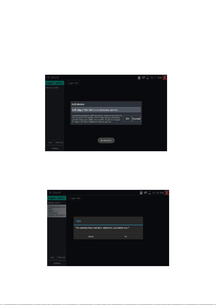
Activate HIKVISION Camera: When connected unactivated HIKVISION Camera, tester can auto
recognized ,And prompt "The camera have not activated, activated it", click "OK" to start activate.
Page.22.
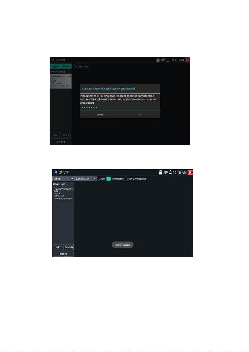
Enter a new password for the camera.
When comes out “activate success” prompt, click login to display camera image.
Page.23.
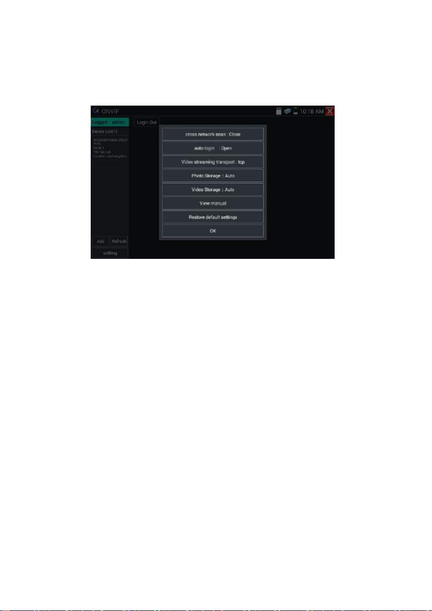
Pop-up settings menu when click the “ONVIF setting” icon in the upper left corner
Across network segments scan: After open this function , enter “Setting - IP Settings - Advanced” to
add other network segments IP, Rapid ONVIF function can across network segments to scan camera’s
IP.
Auto Login : After open this function, tester can auto login camera and display camera image. (The
login password is the same with last time, the first time using password is the default password
"admin")
Video transmission protocol: UTP and TCP protocol.
Open password cracker : Cracks password of cameras.
View manual : Open Manual.
Restore Defaults: Revert “Rapid ONVIF” to default settings.
Confirm : Save the modified parameters.
Page.24.
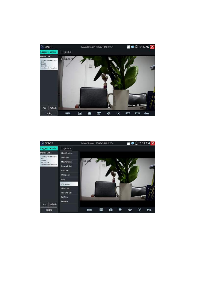
Click “MENU” icon to open camera setting.
While in the “Live video” menu, click “Video Menu” at the top right of the image to access the
following tools: Snapshot, Record, Photo, Playback, PTZ and Settings.
ONVIF PTZ control: Tap the image in the direction you want the PTZ camera to move. Tap the left
side of the image to move left, right to go right, up to go up and down to go down. Compatible IP PTZ
cameras will rotate accordingly. PTZ rotation direction is displayed on top left corner of the image.
Page.25.
 Loading...