


Avycon AVK-HN41B4-2T, AVK-HN41B6-4T, AVK-HN41E4-2T, AVK-HN41E6-4T, AVK-HN41V4-2T User Manual
...
Notes
Please read this user manual carefully to ensure that you can use the device correctly and safely.
There may be several technically incorrect places or printing errors in this manual. The updates will be added into the new version of this manual. The contents of this manual are subject to change without notice.
This device should be operated only from the type of power source indicated on the marking label. The voltage of the power must be verified before using the same. Kindly remove the cables from the power source if the device is not to be used for a long period of time.
Do not install this device near any heat sources such as radiators, heat registers, stoves or other devices that produce heat.
Do not install this device near water. Clean only with a dry cloth.
Do not block any ventilation openings and ensure proper ventilation around the machine.
Do not power off the device at normal recording condition.
This machine is for indoor use only. Do not expose the machine in rain or moist environment. In case any solid or liquid get inside the machine’s case, please turn off the device immediately and get it checked by a qualified technician.
Do not try to repair the device by yourself without technical aid or approval.
When this product is in use, the relevant contents of Microsoft, Apple and Google will be involved in. The pictures and screenshots in this manual are only used to explain the usage of our product. The ownerships of trademarks, logos and other intellectual properties related to Microsoft, Apple and Google shall belong to the above-mentioned companies.
This manual is suitable for many models. All examples and pictures used in the manual are from one of the models for reference purpose.

|
|
|
|
Contents |
...................................................................................................................................... |
i |
|
1 Introduction ....................................................................................................................... |
1 |
||
1.1 ..................................................................................................................... |
Summary |
1 |
|
1.2 ....................................................................................................................... |
Features |
1 |
|
1.3 ............................................................................................. |
Front Panel Descriptions |
4 |
|
1.4 .............................................................................................. |
Rear Panel Descriptions |
4 |
|
1.5 ................................................................................................................ |
Connections |
7 |
|
2 Basic Operation Guide .................................................................................................... |
10 |
||
2.1 |
Startup & Shutdown.................................................................................................. |
10 |
|
|
2.1.1 |
Startup ............................................................................................................ |
10 |
|
2.1.2 |
Shutdown ....................................................................................................... |
10 |
2.2 |
Remote Controller..................................................................................................... |
10 |
|
2.3 |
Mouse Control .......................................................................................................... |
12 |
|
2.4 |
Text-input Instruction................................................................................................ |
12 |
|
2.5 |
Common Button Operation ....................................................................................... |
13 |
|
3 Wizard & Main Interface ............................................................................................... |
14 |
||
3.1 |
Startup Wizard........................................................................................................... |
14 |
|
3.2 |
Main Interface ........................................................................................................... |
19 |
|
|
3.2.1 |
Main Interface Introduction ........................................................................... |
19 |
|
3.2.2 |
Setup Panel..................................................................................................... |
20 |
|
3.2.3 |
Main Functions .............................................................................................. |
22 |
4 Camera Management ...................................................................................................... |
24 |
||
4.1 |
Add/Edit Camera ...................................................................................................... |
24 |
|
|
4.1.1 |
Add Camera ................................................................................................... |
24 |
|
4.1.2 |
Edit Camera.................................................................................................... |
25 |
4.2 |
Add/Edit Camera Group ........................................................................................... |
26 |
|
|
4.2.1 |
Add Camera Group ........................................................................................ |
26 |
|
4.2.2 |
Edit Camera Group ........................................................................................ |
27 |
5 Live Preview Introduction .............................................................................................. |
28 |
||
5.1 |
Preview Interface Introduction.................................................................................. |
28 |
|
5.2 |
Preview Mode ........................................................................................................... |
29 |
|
|
5.2.1 Preview By Display Mode ............................................................................. |
29 |
|
|
5.2.2 |
Quick Sequence View .................................................................................... |
30 |
|
5.2.3 Camera Group View In Sequence .................................................................. |
31 |
|
|
5.2.4 |
Scheme View In Sequence ............................................................................. |
31 |
5.3 |
Preview Image Configuration ................................................................................... |
32 |
|
|
5.3.1 |
OSD Settings.................................................................................................. |
32 |
|
5.3.2 |
Image Settings................................................................................................ |
33 |
|
5.3.3 |
Mask Settings................................................................................................. |
33 |
|
5.3.4 |
Image Adjustment .......................................................................................... |
34 |
i

|
|
|
|
6 PTZ |
................................................................................................................................... |
37 |
|
6.1 ........................................................................... |
PTZ Control Interface Introduction |
37 |
|
6.2 ............................................................................................................ |
Preset Setting |
40 |
|
6.3 ............................................................................................................ |
Cruise Setting |
41 |
|
7 Record & Disk Management .......................................................................................... |
43 |
||
7.1 |
Record Configuration................................................................................................ |
43 |
|
|
7.1.1 |
Mode Configuration ....................................................................................... |
43 |
|
7.1.2 |
Advanced Configuration ................................................................................ |
44 |
7.2 |
Encode Parameters Setting........................................................................................ |
45 |
|
7.3 |
Schedule Setting........................................................................................................ |
45 |
|
|
7.3.1 |
Add Schedule ................................................................................................. |
45 |
|
7.3.2 |
Record Schedule Configuration ..................................................................... |
48 |
7.4 |
Record Mode ............................................................................................................ |
48 |
|
|
7.4.1 |
Manual Recording.......................................................................................... |
48 |
|
7.4.2 |
Timing Recording .......................................................................................... |
49 |
|
7.4.3 |
Motion Based Recording................................................................................ |
49 |
|
7.4.4 |
Sensor Based Recording................................................................................. |
49 |
7.5 |
Disk Management..................................................................................................... |
49 |
|
|
7.5.1 |
Storage Mode Configuration .......................................................................... |
49 |
|
7.5.2 View Disk and S.M.A.R.T. Information ......................................................... |
50 |
|
8 Playback & Backup......................................................................................................... |
52 |
||
8.1 |
Instant Playback........................................................................................................ |
52 |
|
8.2 |
Playback Interface Introduction ................................................................................ |
52 |
|
8.3 |
Record Search & Playback........................................................................................ |
55 |
|
|
8.3.1 Search & Playback by Time-sliced Image...................................................... |
55 |
|
|
8.3.2 Search & Playback by Time ........................................................................... |
56 |
|
|
8.3.3 Search & Playback by Event .......................................................................... |
57 |
|
|
8.3.4 Search & Playback by Tag ............................................................................. |
58 |
|
8.4 |
Backup ...................................................................................................................... |
58 |
|
|
8.4.1 |
Backup by Time ............................................................................................. |
58 |
|
8.4.2 |
Backup by Event ............................................................................................ |
59 |
|
8.4.3 |
Image Management ........................................................................................ |
60 |
|
8.4.4 |
View Backup Status ....................................................................................... |
61 |
9 Alarm Management ........................................................................................................ |
62 |
||
9.1 |
Sensor Alarm............................................................................................................. |
62 |
|
9.2 |
Motion Alarm............................................................................................................ |
63 |
|
|
9.2.1 |
Motion Configuration..................................................................................... |
63 |
|
9.2.2 |
Motion Alarm Handling Configuration .......................................................... |
64 |
9.3 |
Exception Alarm ....................................................................................................... |
64 |
|
|
9.3.1 |
Exception Handling Settings .......................................................................... |
64 |
|
9.3.2 |
IPC Offline Settings ....................................................................................... |
65 |
9.4 |
Alarm Event Notification .......................................................................................... |
65 |
|
|
9.4.1 |
Alarm-out ....................................................................................................... |
65 |
ii

|
|
|
|
|
|
|
|
|
9.4.2 |
66 |
|
|
|
|
9.4.3 |
Display ........................................................................................................... |
66 |
|
|
|
9.4.4 |
Buzzer ............................................................................................................ |
66 |
|
9.5 |
Manual Alarm ........................................................................................................... |
67 |
||
|
9.6 |
View Alarm Status .................................................................................................... |
67 |
||
10 Account & Permission Management.............................................................................. |
69 |
||||
|
10.1 |
Account Management ............................................................................................. |
69 |
||
|
|
|
10.1.1 |
Add User ...................................................................................................... |
69 |
|
|
|
10.1.2 |
Edit User ...................................................................................................... |
70 |
|
10.2 User Login & Logout .............................................................................................. |
71 |
|||
|
10.3 |
Permission Management ......................................................................................... |
71 |
||
|
|
|
10.3.1 |
Add Permission Group ................................................................................. |
71 |
|
|
|
10.3.2 |
Edit Permission Group ................................................................................. |
73 |
|
10.4 Black and White List............................................................................................... |
73 |
|||
11 |
Device Management ........................................................................................................ |
74 |
|||
|
11.1 |
Network Configuration ........................................................................................... |
74 |
||
|
|
|
11.1.1 |
TCP/IPv4 Configuration............................................................................... |
74 |
|
|
|
11.1.2 |
Port Configuration........................................................................................ |
75 |
|
|
|
11.1.3 |
DDNS Configuration.................................................................................... |
76 |
|
|
|
11.1.4 |
E-mail Configuration.................................................................................... |
78 |
|
|
|
11.1.5 |
UPnP Configuration ..................................................................................... |
79 |
|
|
|
11.1.6 |
NAT Configuration....................................................................................... |
80 |
|
|
|
11.1.7 |
View Network Status.................................................................................... |
80 |
|
11.2 |
Basic Configuration ................................................................................................ |
80 |
||
|
|
|
11.2.1 |
Common Configuration................................................................................ |
80 |
|
|
|
11.2.2 Date and Time Configuration ....................................................................... |
81 |
|
|
11.3 |
Factory Default........................................................................................................ |
82 |
||
|
11.4 |
Device Software Upgrade ....................................................................................... |
82 |
||
|
11.5 |
Backup and Restore................................................................................................. |
82 |
||
|
11.6 |
View Log................................................................................................................. |
83 |
||
|
11.7 |
View System Information........................................................................................ |
83 |
||
12 |
Remote Surveillance ........................................................................................................ |
84 |
|||
|
12.1 |
Mobile Client Surveillance ..................................................................................... |
84 |
||
|
12.2 |
Web LAN Access .................................................................................................... |
84 |
||
|
12.3 |
Web WAN Access ................................................................................................... |
85 |
||
|
12.4 |
Web Remote Control............................................................................................... |
86 |
||
|
|
|
12.4.1 |
Remote Preview ........................................................................................... |
87 |
|
|
|
12.4.2 |
Remote Playback.......................................................................................... |
90 |
|
|
|
12.4.3 |
Remote Backup ............................................................................................ |
91 |
|
|
|
12.4.4 |
Remote Configuration .................................................................................. |
91 |
Appendix A FAQ ................................................................................................................... |
92 |
||||
Appendix B Calculate Recording Capacity ........................................................................ |
98 |
||||
iii

Appendix C Compatible Device List ................................................................................... |
99 |
iv

1 Introduction
1.1 Summary
Based on the most advanced SOC technology and embedded system in the field, this series of the NVR adopt the new designed human interface and support the smart management of the IP camera and the record search of slice. This series of the NVR which are powerful and easy to use are provided with excellent image quality and stable system. They are centralized monitoring management products with high performance and high quality specially designed for network video monitoring field.
This series of the NVR can be widely used to security system of banks at home and abroad, schools, intelligent mansions, traffic, environmental protection, supermarkets, petrol service stations, residential quarters and factories and so on.
1.2 Features
Basic Functions
Support network device access including IP camera/dome and the third party IP cameras
Some NVRs support the latest H.265 video coding stream and a mixture input of H.265 and H.264 IP cameras
Support standard ONVIF protocol
Support dual stream recording of each camera (max 5MP resolution)
Support IP cameras to be added quickly or manually
Support batch or single configuration of the cameras’ OSD, video parameters, mask, motion and so on
Support a maximum of 8 user permission groups including Administrator, Advanced and Ordinary which are the default permission groups of the system
Support a maximum of 16 users to be created, multiple web clients login by using one username at the same time and the user’s permission control to be enabled or disabled
Support a maximum of 10 web clients login at the same time
Live Preview
Support 4K×2K/1920×1080/1280×1024 HDMI and 1920×1080/1280×1024 VGA high definition synchronous display
Support multi-screen modes such as 1/4/6/8/9/16/25/36
Support auto adjustment of the camera’s image display proportion
Support audio monitoring of the camera to be enabled or disabled
Support manual snap of the preview camera
Support the sequence of the preview cameras to be adjusted
Support display mode to be added and saved and the saved modes can be called directly
Support quick tool bar operation of the preview window
Support camera group view and scheme view in sequence, quick sequence view and dwell time setting
Support motion detection and video mask
1

Support multiple popular P.T.Z. control protocol and setup of the preset and cruise
Support direct mouse control of the IP dome including rotating, zoom, focusing and so on
Support single camera image to be zoomed by sliding the scroll wheel of the mouse
Support any area of the image to be zoomed in to a maximum of 16 times of the current
size
Support image and lens adjustment (only available for some cameras)
Support quick camera adding in the camera window of the live preview interface
Disk Management
The NVRs with the 2U case can add a maximum of 8 SATA HDDs; a maximum of 4 SATA HDDs with the 1.5U case, a maximum of 2 SATA HDDs with the 1U case and a maximum of 1 SATA HDD with the small 1U case
Each SATA interface of the NVR supports the HDDs with max 6TB storage capacity
Some of the NVRs support record to be backed up by e-SATA HDD
Support disk group configuration and management and each camera can be added into different disk groups with different storage capacity
Support disk information and disk working status viewing
Support batch formatting of the disks
Record Configuration
Support main stream and sub stream recording at the same time and batch or single configuration of the record stream
Support manual and auto record modes
Support schedule recording, sensor alarm recording and motion detection recording
Support schedule recording and event recording setting with different record streams
Support record schedule setting and recycle recording
Support pre recording and delay recording configuration of the event recording
Record Playback
Support time scale operation in quick playback and the playback date and time can be set randomly by scrolling the mouse; the time interval of the time scale can be zoomed
Support record searching by time slice/time/event/tag
Support time view and camera view in searching by time slice mode
Support time slice searching by month, by day, by hour and by minute and time slice to be displayed with camera thumbnail
Support a maximum of 16 cameras to be searched by time
Support event searching by manual/motion/sensor events
Support tag searching by the manual added tags
Support instant playback of the selected camera in the live preview interface
Support a maximum of 16 synchronous playback cameras
Support acceleration(maximum 32 times of the normal speed), deceleration (minimum 1/32 times of the normal speed) and 30s’ addition or reduction to current playing time
Record Backup
Support record to be backed up through USB (U disk, mobile HDD) or e-SATA interface
2

Support record to be backed up by time/event/image searching
Support record cutting for backing up when playing back
Support a maximum of 10 backup tasks in background and backup status viewing
Alarm Management
Support alarm schedule setting
Support enabling or disabling of the motion detection, external sensor alarm input and exception alarms including IP address conflict alarm, disk IO error alarm, disk full alarm, no disk alarm, illegal access alarm, network disconnection alarm, IPC offline alarm and so on, alarm trigger configuration supportable
Support IPC offline alarm trigger configuration of PTZ, snap, pop-up video, etc.
Support event notification modes of alarm-out, pop-up video, pop-up message box, buzzer, e-mail and so on
The snapped images can be attached into the e-mail when alarm linkage is triggered
Support alarm status view of alarm-in, alarm-out, motion detection and exception alarm
Support alarm to be triggered and cleared manually
Support system auto reboot when exception happens
Network Functions
Support TCP/IP and PPPoE, DHCP, DNS, DDNS, UPnP, NTP, SMTP protocol and so on
Support allow and block list function and the allow and block IP address/IP segment/MAC address can be set
Support multiple browsers including IE8/9/10/11, Firefox, Opera, Chrome (available only for the versions lower than 45) and Safari in MAC system
Support remote achievement, configuration, import and export of the NVR parameters and other system maintenance operations including remote upgrading and system restart
Support remote camera configuration of the NVR including video parameters, image quality and so on
Support remote searching, playback and backup of the NVR
Support manual alarm to be triggered and cleared remotely
Support NVMS or other platform management software to access the NVR and manage it
Support NAT function and QRCode scanning by mobile phone and PAD
Support mobile surveillance by phones or PADs with iOS or Android OS
Support NVR to be accessed remotely through telnet and the telnet function can be enabled or disabled
Other Functions
The NVR can be controlled and operated by the buttons on the front panel, the remote controller and the mouse
Setting interfaces can be switched to one another conveniently by clicking the main menus on the top of the setting interfaces
Support NVR information viewing including basic, camera status, alarm status, record status, network status, disk and backup status
Support factory restoring, import and export of the system configuration, log view and export and local upgrading by USB mobile device
3

Support auto recognition of the displayer’s resolution
1.3Front Panel Descriptions
The following descriptions are for reference only.
Type I:
Name |
Descriptions |
REC |
When recording, the light is blue |
|
|
Net |
When access to network , the light is blue |
|
|
Power |
Power indicator, when connection , the light is blue |
|
|
Fn |
No function temporarily |
|
|
Type II:
Name |
|
Descriptions |
Power |
|
Power Indicator, when connected, the light is blue |
|
|
|
HDD |
|
The light turns blue when reading/writing HDD |
|
|
|
Net |
|
The light turns blue when it is able to access the network |
|
|
|
Backup |
|
The light turns blue when backing up files and data |
|
|
|
Play |
|
The light turns blue when playing video |
|
|
|
REC |
|
Power Indicator, when connected, the light is blue |
|
|
|
AUDIO /+ |
|
1. Adjust audio 2. Increase the value in setup |
|
|
|
P.T.Z / - |
|
1. Enter PTZ mode 2. Decrease the value in setup |
|
|
|
MENU |
|
Enter Menu in live |
|
|
|
INFO |
|
Check the information of the device |
|
|
|
BACKUP |
|
Enter backup mode in live |
|
|
|
SEARCH |
|
Enter search mode in live |
|
|
|
Exit |
|
Exit the current interface |
|
|
|
|
|
Manually record |
|
|
|
|
|
Play/Pause |
|
|
|
|
|
Speed down |
|
|
|
|
|
Speed up |
|
|
|
1-9 |
|
Input digital number and select camera |
|
|
|
0/-- |
|
Input number 0, the number above 10 |
|
|
|
Direction Key |
|
Change direction |
|
|
|
Multi-Screen Switch |
|
Change the screen mode |
|
|
|
Enter |
|
Confirm selection |
|
|
|
USB |
|
To connect external USB device like USB mouse or USB |
|
flash |
|
|
|
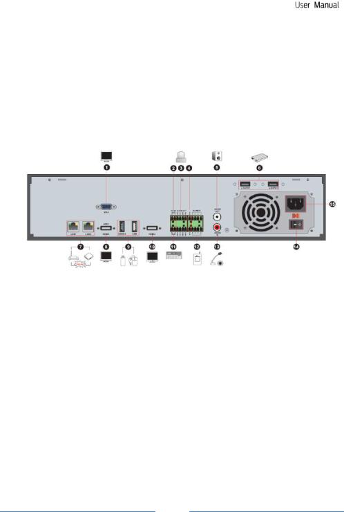
1.4 Rear Panel Descriptions
Here we only take a part of real panels for example to introduce their interfaces and connections. The interfaces and locations of the interfaces are only for references. Please take the real object as the standard.
4
|
|
|
|
|
|
|
|
|
|
|
|
|
|
|
|
|
|
|
No. |
|
|
Name |
|
Descriptions |
|
|
|
1 |
|
|
ALARM OUT |
|
Relay output; connect to external alarm |
|
|
|
|
|
|
|
|
|
|
|
|
2 |
|
|
GND |
|
Grounding |
|
|
|
|
|
|
|
|
|
|
|
|
3 |
|
|
AUDIO IN |
|
Audio input; connect to audio input device, like microphone, |
|
|
|
|
|
|
pickup, etc |
|
|||
|
|
|
|
|
|
|
|
|
|
4 |
|
|
DC12V |
|
DC12V power input |
|
|
|
|
|
|
|
|
|
|
|
|
5 |
|
|
LAN |
|
Network port |
|
|
|
|
|
|
|
|
|
|
|
|
6 |
|
|
VGA |
|
Connect to monitor |
|
|
|
|
|
|
|
|
|
|
|
|
7 |
|
|
ALARM IN |
|
Alarm inputs for connecting sensors |
|
|
|
|
|
|
|
|
|
|
|
|
8 |
|
|
HDMI |
|
Connect to high definition display device |
|
|
|
|
|
|
|
|
|
|
|
|
9 |
|
|
USB |
|
Connect USB storage device or USB mouse |
|
|
|
|
|
|
|
|
|
|
|
|
10 |
|
|
AUDIO OUT |
|
Audio output; connect to sound box |
|
|
|
|
|
|
|
|
|
|
|
|
11 |
|
|
RS485 |
|
Connect to keyboard. A is TX+; B is TX- |
|
|
|
|
|
|
|
|
|
|
|
|
No. |
Name |
|
|
Descriptions |
|
|
1 |
VGA |
Connect to monitor |
|
||
|
|
|
|
|
||
|
2 |
e-SATA |
Connect to HDD with e-SATA interface |
|
||
|
|
|
|
|
||
|
3 |
RS485 Y/Z interface |
Unavailable right now |
|
||
|
|
|
|
|
||
|
4 |
RS485 A/B interface |
Connect to keyboard. A is TX+; B is TX- |
|
||
|
|
|
|
|
||
|
5 |
AUDIO OUT |
Audio output; connect to sound box |
|
||
|
|
|
|
|
|
|
|
|
|
|
5 |
|
|
|
|
|
|
|
|
|
|
|
|
|
|
|
|
|
|
|
|
|
|
|
|
|
|
|
|
No. |
|
|
Name |
|
Descriptions |
|
|
|
6 |
|
|
LAN |
|
Network port |
|
|
|
|
|
|
|
|
|
|
|
|
7 |
|
|
HDMI |
|
Connect to high definition display device |
|
|
|
|
|
|
|
|
|
|
|
|
8 |
|
|
USB |
|
Connect USB storage device or USB mouse |
|
|
|
|
|
|
|
|
|
|
|
|
9 |
|
|
GND |
|
Grounding |
|
|
|
|
|
|
|
|
|
|
|
|
10 |
|
|
ALARM OUT |
|
Relay output; connect to external alarm |
|
|
|
|
|
|
|
|
|
|
|
|
11 |
|
|
ALARM IN |
|
Alarm inputs for connecting sensors |
|
|
|
|
|
|
|
|
|
|
|
|
12 |
|
|
AUDIO IN |
|
Audio input; connect to audio input device, like |
|
|
|
|
|
|
microphone, pickup, etc |
|
|||
|
|
|
|
|
|
|
|
|
|
13 |
|
|
Power Switch |
|
Press the switch to turn on/off the NVR |
|
|
|
|
|
|
|
|
|
|
|
|
14 |
|
|
Power Supply |
|
Power supply interface |
|
|
|
|
|
|
|
|
|
|
|
No. |
|
|
Name |
|
Descriptions |
1 |
|
|
VGA |
|
Connect to monitor |
|
|
|
|
|
|
2 |
|
|
RS485 Y/Z interface |
|
Unavailable right now |
|
|
|
|
|
|
3 |
|
|
ALARM OUT |
|
Relay output; connect to external alarm |
|
|
|
|
|
|
4 |
|
|
GND |
|
Grounding |
|
|
|
|
|
|
5 |
|
|
AUDIO OUT |
|
Audio output; connect to sound box |
|
|
|
|
|
|
6 |
|
|
e-SATA1/ e-SATA2 |
|
Connect to HDD with e-SATA interface |
|
|
|
|
|
|
7 |
|
|
LAN1/LAN2 |
|
Network port |
|
|
|
|
|
|
8 |
|
|
HDMI1 |
|
Connect to 4K×2K high definition display device |
|
|
|
|
|
|
9 |
|
|
USB3.0/USB |
|
USB3.0 and USB 2.0 interface, connect USB storage |
|
|
|
device or USB mouse |
||
|
|
|
|
|
|
10 |
|
|
HDMI2 |
|
Connect to 1920×1080 high definition display device |
|
|
|
|
|
|
11 |
|
|
RS485 A/B interface |
|
Connect to keyboard. A is TX+; B is TX- |
|
|
|
|
|
|
12 |
|
|
ALARM IN |
|
Alarm inputs for connecting sensors |
|
|
|
|
|
|
13 |
|
|
AUDIO IN |
|
Audio input; connect to audio input device, like |
|
|
|
microphone, pickup, etc |
||
|
|
|
|
|
|
14 |
|
|
Power Switch |
|
Press the switch to turn on/off the NVR |
|
|
|
|
|
|
15 |
|
|
Power Supply |
|
Power supply interface |
|
|
|
|
|
|
6

|
|
|
|
|
|
|
|
|
|
|
|
|
|
|
|
|
|
|
No. |
|
|
Name |
|
Descriptions |
|
|
|
1 |
|
|
Power Supply |
|
DC48V power supply interface |
|
|
|
|
|
|
|
|
|
|
|
|
2 |
|
|
PoE port |
|
8 PoE network ports; connect to 8 PoE IP cameras |
|
|
|
|
|
|
|
|
|
|
|
|
3 |
|
|
LAN |
|
Network port |
|
|
|
|
|
|
|
|
|
|
|
|
4 |
|
|
VGA |
|
Connect to monitor |
|
|
|
|
|
|
|
|
|
|
|
|
5 |
|
|
HDMI |
|
Connect to 1920×1080 high definition display device |
|
|
|
|
|
|
|
|
|
|
|
|
6 |
|
|
USB3.0 |
|
USB3.0 interface, connect USB storage device or |
|
|
|
|
|
|
USB mouse |
|
|||
|
|
|
|
|
|
|
|
|
|
7 |
|
|
AUDIO IN |
|
Audio input; connect to audio input device, like |
|
|
|
|
|
|
microphone, pickup, etc |
|
|||
|
|
|
|
|
|
|
|
|
|
8 |
|
|
AUDIO OUT |
|
Audio output; connect to sound box |
|
|
|
|
|
|
|
|
|
|
|
|
9 |
|
|
Power Supply |
|
DC12V power supply interface |
|
|
|
|
|
|
|
|
|
|
|
1.5 Connections
Video Connections
Video Output: Supports VGA/HDMI video output. You can connect to monitor through these video output interfaces simultaneously or independently.
Audio Connections
Audio Input: Connect to microphone, pickup, etc.
Audio Output: Connect to headphone, sound box or other audio output devices.
Alarm Connections
Some models may support this function. Take 16 CH alarm inputs and 1 CH alarm output for example.
7
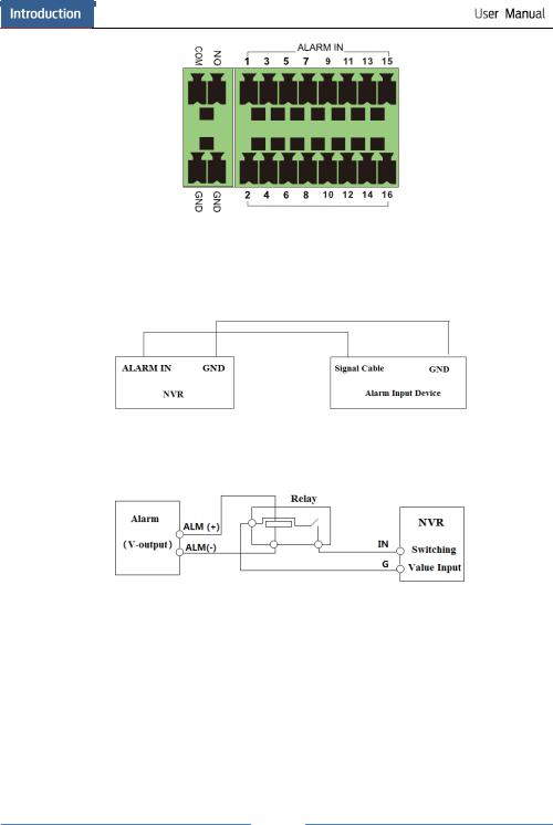
Alarm Input:
Alarm IN 1~16 are 16 CH alarm input interfaces. There are no type requirements for sensors. NO type and NC type are both available.
The way to connect sensor and the device is as shown below:
The alarm input is an open/closed relay. If the input is not an open/closed relay, please refer to the following connection diagram:
Alarm Output:
The way to connect alarm output device:
Pull out the green terminal blocks and loosen the screws in the alarm-out port. Then insert the signal wires of the alarm output devices into the port of NO and COM separately. Finally, tighten the screws. Provided that the external alarm output devices need power supply, you can connect the power supply as per the following figures.
8

RS485 Connection
There are two types of RS485 interfaces:
Type 1 |
Type 2 |
Type 1: The P/Z interfaces are unavailable temporarily. K/B interfaces are used to connect keyboard.
Type 2: The RS485 interfaces are used to connect keyboard. A is TX+; B is TX-.
9

2Basic Operation Guide
2.1Startup & Shutdown
Please make sure all the connections are done properly before you power on the unit. Proper startup and shutdown are crucial to expending the life of your device.
2.1.1Startup
Connect the output display device to the VGA/HDMI interface of the NVR.
Connect with the mouse and power. The device will boot and the power LED would turn blue.
A WIZARD window will pop up (you should select the display language the first time you use the NVR). Refer to 3.1 Startup Wizard for details.
2.1.2 Shutdown
You can power off the device by using remote controller or mouse.
By remote controller:
Press Power button. This will take you to a shutdown window. The unit will power off after a while by clicking “OK” button.
Disconnect the power.
By mouse:
Click StartShutdown to pop up the Shutdown window. Select “Shutdown” in the window. The unit will power off after a while by clicking “OK” button.
Disconnect the power.
2.2Remote Controller
It uses two AAA size batteries.
Open the battery cover of the remote controller.
Place batteries. Please take care the polarity (+ and -).Replace the battery cover.
Key points to check in case the remote doesn’t work.
1.Check batteries polarity.
2.Check the remaining charge in the batteries.
3.Check IR controller sensor for any masking.
If it still doesn’t work, please change a new remote controller to try, or contact your dealers. You can just turn the IR sensor of the remote controller towards the IR receiver of the NVR to control it when you are controlling multiple devices by remote controller.
There are two kinds of remote controller. The interface of remote controller is shown as below.
10

|
|
|
|
|
|
|
|
|
|
|
|
|
Button |
Function |
|
|
|
Power Button |
Switch off—to stop the device |
|
|
|
|
|
|
|
|
Record Button |
To start recording |
|
|
|
||
|
-/-- /0-9 |
Input number or choose camera |
||
|
|
|
|
|
|
|
|
Fn1 Button |
Unavailable temporarily |
|
|
|
|
|
|
|
|
Multi Button |
To choose multi screen display mode |
|
|
|
|
|
|
|
|
Next Button |
To switch the live image |
|
|
|
|
|
|
|
|
SEQ |
To go to sequence view mode |
|
|
|
|
|
|
|
|
Audio |
To enable audio output in live mode |
|
|
|
|
|
|
|
|
Switch |
No function temporarily |
|
|
|
|
|
|
|
|
Direction button |
To move cursor in setup or pan/title PTZ |
|
|
|
|
|
|
|
|
Enter Button |
To confirm the choice or setup |
|
|
|
|
|
|
|
|
Menu Button |
To go to menu |
|
|
|
|
|
|
|
|
Exit Button |
To exit the current interface |
|
|
|
|
|
|
|
|
Focus/IRIS/Zoom/PTZ |
To control PTZ camera |
|
|
|
|
|
|
|
|
Preset Button |
To enter into preset setting in PTZ mode |
|
|
|
|
|
|
|
|
Cruise Button |
To go to cruise setting in PTZ mode |
|
|
|
|
|
|
|
|
Track Button |
No track function temporarily |
|
|
|
|
|
|
|
|
Wiper Button |
No function temporarily |
|
|
|
|
|
|
|
|
Light Button |
No function temporarily |
|
|
|
|
|
|
|
|
Clear Button |
No function temporarily |
|
|
|
|
|
|
|
|
Fn2 Button |
No function temporarily |
|
|
|
|
|
|
|
|
Info Button |
Get information about the device |
|
|
|
|
|
|
|
|
|
To control playback. Play(Pause)/Stop/Previous |
|
|
|
|
Frame/Next Frame/Speed Down/Speed Up |
|
|
|
Snap Button |
To take snapshots manually |
|
|
|
|
|
|
|
|
Search Button |
To go to search mode |
|
|
|
|
|
|
|
|
Cut Button |
No function temporarily |
|
|
|
|
|
|
|
|
Backup Button |
To go to backup mode |
|
|
|
|
|
|
|
|
Zoom Button |
To zoom in the images |
|
|
|
|
|
|
|
|
PIP Button |
No function temporarily |
|
|
|
|
|
Note:
You shall press P.T.Z button to enter PTZ setting mode, choose a channel and press P.T.Z button again to hide the P.T.Z control panel. Then you can press preset, cruise, track, wiper or light button to enable the relevant function.
11

|
|
|
|
|
|
|
|
|
|
Button |
Function |
|
|
REC |
Record manually |
|
|
|
|
|
|
Search |
To enter search mode |
|
|
|
|
|
|
MEUN |
To enter menu |
|
|
|
|
|
|
Exit |
To exit the current interface |
|
|
|
|
|
|
ENTER |
To confirm the choice or setup |
|
|
|
|
|
|
Direction button |
To move cursor in setup |
|
|
|
|
|
|
ZOOM |
To zoom in |
|
|
|
|
|
|
PIP |
No function temporarily |
|
|
|
|
|
|
|
To control playback. Play(Pause)/Next Frame/Speed |
|
|
|
Up/Stop/Previous Frame/Speed Down |
|
|
Multi |
To choose multi screen display mode |
|
|
|
|
|
|
Next |
To switch the live image |
|
|
|
|
|
|
SEQ |
To go to sequence view mode |
|
|
|
|
|
|
INFO |
Get information about the device |
|
|
|
|
2.3 Mouse Control
Mouse control in Live Preview & Playback interface
In the live preview & playback interface, double click on any camera window to show the window in single screen mode; double click the window again to restore it to the previous size.
In the live preview & playback interface, if the interfaces display in full screen, move the mouse to the bottom of the interface to pop up a tool bar. The tool bar will disappear automatically after you move the mouse away from it for some time; move the mouse to the right side of the interface to pop up a panel and the panel will disappear automatically after you move the mouse away from it.
Mouse control in text-input
Move the mouse to the text-input box and then click the box. The input keyboard will pop up automatically.
Note: Mouse is the default tool for all operations unless an exception as indicated.
2.4 Text-input Instruction
12
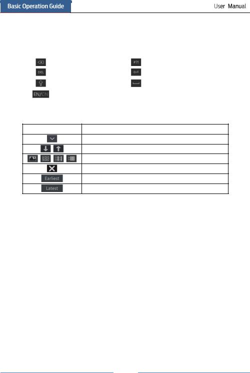
The system includes two input boxes. Refer to the above pictures. The left box is the number input box and the right box is the input box which provides inputs of numbers, letters and punctuation characters. The introductions of keys on the input boxes are shown below.
Button |
|
Meaning |
Button |
|
Meaning |
|
|
Backspace key |
|
|
Switch key of punctuation character |
|
|
|
|
|
|
|
|
Delete Key |
|
|
Enter key |
|
|
|
|
|
|
|
|
Switch key between upper |
|
|
Space key |
|
|
and lower letter |
|
|
|
|
|
|
|
|
|
|
|
Switch key of language |
|
|
|
|
|
|
|
|
|
2.5 Common Button Operation
Button |
Meaning |
|
|
Click it to show the menu list.
Click it to change the sequence of the list.
Click it to change the camera displaying mode.
Click it to close the current interface.
Click it to go to the earliest date of camera recording.
Click it to go to the latest date of camera recording.
13
3Wizard & Main Interface
3.1Startup Wizard
The disk icons will be shown on the top of the startup interface. You can view the number and status of each disk quickly and conveniently through these icons ( : no disk;
  : unavailable disk;
  : RW available disk).
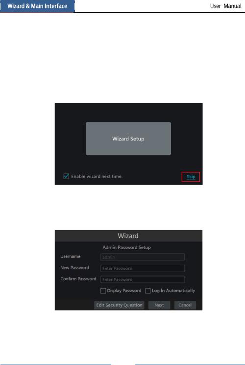
You can quickly configure the NVR by wizard setup to make the NVR work normally. You must configure the wizard if you start the NVR for the first time (or click “Skip” to cancel the wizard next time).
Click “Wizard Setup” to start wizard. The setting steps are as follows.
System Login. Set your own password or use the default when you use the wizard for the first time (the default username of the system is admin and the default password of admin is 123456); select the login username and enter the corresponding password next time.
Click “Edit Security Question” to set questions and answers for password security of admin. If you forget the password, please refer to Q4 in Appendix A FAQ for details.
Click “Next” to continue or click “Cancel” to exit the wizard.
14
Date and Time Configuration. The date and time of the system need to be set up if you use the wizard for the first time. Refer to the following figure. Set the time zone, system time, date format and time format. The DST will be enabled by default if the time zone selected includes DST. Click “Next” to continue.
Network Settings. Check “Obtain an IP address automatically” and “Obtain DNS automatically” to get the IP address and DNS automatically (the DHCP function of the router in the same LAN should also be enabled), or manually input them. Input the HTTP port, RTSP port and Server port (please see 11.1.2 Port Configuration for details). Click “Next” to continue.
15
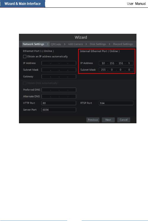
Note:
If you use the NVR with the PoE network ports, the online state of the internal ethernet port will be shown on the interface. Refer to the picture below. Please refer to 11.1.1 TCP/IPv4 Configuration for detail introduction of the internal ethernet port.
QRCode. You can scan the QRCode through mobile client which is installed in the mobile phone or PAD to log in the mobile client instantly. Please refer to 12.1 Mobile Client Surveillance for details.
Add Camera. Click “Refresh” to refresh the list of online IP cameras which are in the same local network with NVR and then click  to add the searched camera. Click “Add All” to add all the cameras in the list. Click
  to delete the added camera. Click “Delete All” to delete all the added cameras.
16
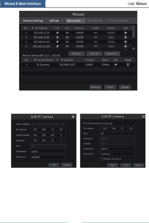
Click  to edit the searched IP camera as shown on the below left. Input the new IP address, subnet mask, gateway, username and the password of the camera. Click “OK” to save the settings.
Click  to edit the added camera as shown on the above right. Input the new camera name, IP address, port, username and the password of the camera. You can click “Test” to test the effectiveness of the input information. Click “OK” to save the settings. You can change the IP camera name only when the added camera is online. Click “Next” to continue.
Disk Settings. You can view the disk number, disk capacity of the NVR and serial number, R&W status of the disk. Click “Formatting” to format the disk. Click “Next” to continue.
17
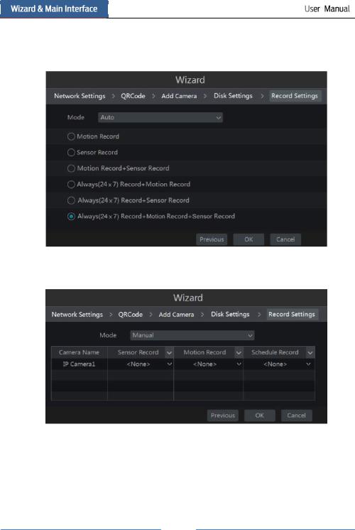
Record Settings. Two record modes are available: auto and manual.
Auto: Select one auto mode in the interface as shown below and then click “OK” button to save the settings. See 7.1.1 Mode Configuration for details.
Manual: Set the “Sensor Record”, “Motion Record” and “Schedule Record” of each camera. Click “OK” to save the settings. See 7.1.1 Mode Configuration for details.
18
3.2 Main Interface
3.2.1 Main Interface Introduction
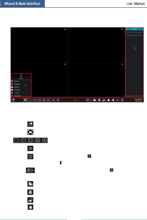
The buttons in area are introduced in the table below.
Button |
|
|
Meaning |
|
|
Start button. Click it to pop up area . |
|
||
|
|
|||
|
Full screen button. Click it to show full screen; click it again to exit the full |
|||
|
screen. |
|
|
|
|
|
|
|
|
|
Screen mode button. |
|
|
|
|
|
|||
|
Dwell button (see 5.2.2 Quick Sequence View and 5.2.4 Scheme View In |
|||
|
Sequence for details). |
|
|
|
|
|
|
|
|
|
Click it to enable OSD; click |
to disable OSD. |
|
|
|
|
|
||
|
Click |
to set the default playback time before starting instant playback (8.1 |
||
|
Instant Playback) or going to the playback interface for playback operations |
|||
|
(8.2 |
Playback Interface Introduction); click |
to go to the playback |
|
|
interface. For instance, if you choose “5 minutes ago” as the default playback |
|||
|
time, you can playback the record from the past five minutes. |
|||
|
|
|||
|
Manual record button. Click it to enable/disable record. |
|||
|
|
|||
|
Manual alarm button. Click it to trigger or clear the alarm-out manually in the |
|||
|
popup window. |
|
|
|
|
|
|||
|
Record status button. Click it to view the record status. |
|||
|
|
|
||
|
Alarm status button. Click it to view the alarm status. |
|
||
|
|
|
|
|
19
|
|
|
|
|
|
|
|
|
Button |
|
Meaning |
|
|
|
|
Disk status button. Click it to view the disk status and RAID status.
Network status button. Click it to view the network status.
Information button. Click it to view system information.
Introduction of area :
Click “Camera” to view all the added cameras in the camera list. Select one camera window on the left side of the interface and then double click one camera in the list to preview the camera image in the selected window.
Click “Single Channel Sequences” to view all the added groups in the group list; click one group in the list to view all the added cameras in the group (refer to 4.2 Add/Edit Camera Group for detail configuration of the camera group). Select one camera window on the left side of the interface and then double click one group in the group list to preview the cameras’ images one by one in the selected window.
Click “Customize Display Modes” to view all the display modes in the display mode list (refer to 5.2.1 Preview By Display Mode for detail configuration of the display mode). Double click one display mode in the list to switch to the display mode for previewing.
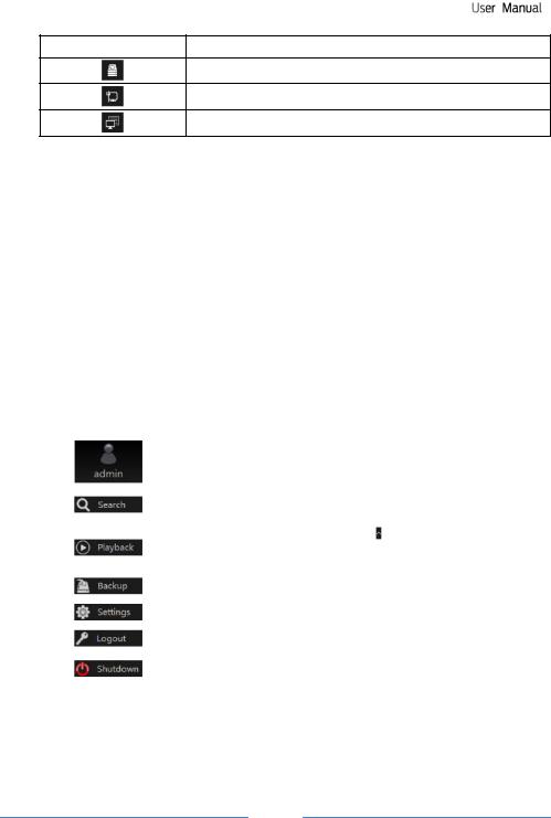
Introduction of area |
: |
|
|
|
|
|
|
Icon / Button |
|
Meaning |
|
|
|
It shows the current login user. |
|
|
|
|
|
|
|
Click it to go to record search interface, see 8.3 Record Search & |
|
|
|
Playback for details. |
|
|
|
|
|
|
|
Click it to go to playback interface (click |
on the tool bar at the |
|
|
bottom of the live preview interface to set the default playback time), |
|
|
|
see 8.2 Playback Interface Introduction for details. |
|
|
|
|
|
|
|
Click it to go to backup interface, see 8.4 Backup for details. |
|
|
|
|
|
|
|
Click it to pop up the setup panel, see 3.2.2 Setup Panel for details. |
|
|
|
|
|
|
|
Click it to log out the system. |
|
|
|
|
|
|
|
Click it and then select “Logout”, “Reboot” or “Shutdown” in the |
|
|
|
popup window. |
|
|
|
|
|
3.2.2 Setup Panel
Click StartSettings to pop up the setup panel as shown below.
20

The setup panel includes seven modules. Each module provides some function entries with links for convenient operation.
Here we take Camera module as an example. The Camera module provides convenient links such as “Add Camera”, “Edit Camera”, “Image Settings”, “Motion” and “PTZ”. Click Camera to go to the camera management interface as shown below.
There are some function items on the left side of the camera management interface. Click each item to go to corresponding interface or window. For instance, click “Add Camera” to pop up the window as shown below.
21
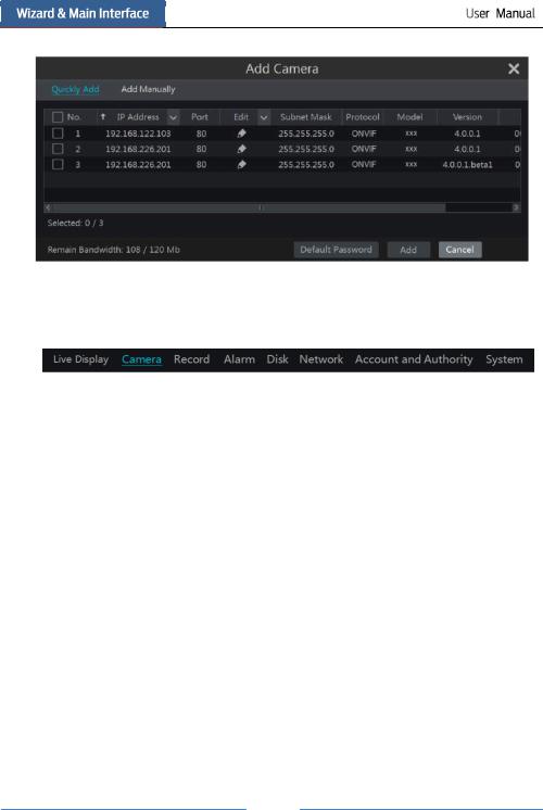
Click the main menus on the top of the camera management interface to go to corresponding interfaces. Refer to the picture below. For instance, you can go to system setup interface by clicking “System” tag.
3.2.3Main Functions
Camera
The module covers the functions such as Camera Management (see Chapter 4 Camera Management for details), Image Settings (see 5.3 Preview Image Configuration for details), Motion (see 9.2.1 Motion Configuration for details) and PTZ (see Chapter 6 PTZ for details) and so on.
Record
The module covers the functions such as Encode Parameters and Record Schedule and so on. Please see Chapter 7 Record & Disk Management for details.
Disk
The module covers the functions such as Disk Management, Storage Mode and Disk Information and so on. Please see Chapter 7 Record & Disk Management for details.
Alarm
The module covers the functions such as Sensor and Motion Alarm Handling and Alarm Out Settings. Please see Chapter 9 Alarm Management for details.
Network
The module covers the functions such as TCP/IPv4, DDNS, Port, E-mail and Network Status
22

and so on. Please see 11.1 Network Configuration for details.
Account and Authority
The module covers the functions such as Account Management (see 10.1 Account Management for details) and Permission Management (see 10.3 Permission Management for details) and so on.
System
The module covers the functions such as Basic Configuration (see 11.2 Basic Configuration for details), Device Information (see 11.7 View System Information for details), Log Information (see 11.6 View Log for details) and Configuration File Import&Export (see 11.5 Backup and Restore for details) and so on.
23

4Camera Management
4.1Add/Edit Camera
4.1.1 Add Camera
The network of the NVR should be set before adding IP camera (see 11.1.1 TCP/IPv4 Configuration for details).
Refer to the pictures below. Click Add Camera in the setup panel or  in the top right corner of the preview window to pop up the “Add Camera” window as shown below. You can quickly add or add the IP camera manually.
Quickly Add
Check the cameras and then click “Add” to add cameras. Click  to edit the camera’s IP address, username and password and so on. Click “Default Password” to set the default username and password of each camera.
24
 Loading...