

Page 1

EVR1500
Installer/User Guide
Page 2
INSTRUCTIONS
This symbol is intended to alert the user to the presence of important operating
and maintenance (servicing) instructions in the literature accompanying
the appliance.
DANGEROUS VOLTAGE
This symbol is intended to alert the user to the presence of uninsulated
dangerous voltage within the product’s enclosure that may be of sufficient
magnitude to constitute a risk of electric shock to persons.
PROTECTIVE GROUNDING TERMINAL
This symbol indicates a terminal which must be connected to earth ground
prior to making any other connections to the equipment.
Page 3

EVR1500
Installer/User Guide
Avocent, the Avocent logo, The Power of Being There and
DSView are registered trademarks of Avocent Corporation.
All other marks are the property of their respective owners.
© 2004 Avocent Corporation. All rights reserved.
Page 4

USA Notification
Canadian Notification
Japanese Approvals
Safety and
EMC Standards
Warning: Changes or modifications to this unit not expressly approved by the party
responsible for compliance could void the user's authority to operate the equipment.
Note: This equipment has been tested and found to comply with the limits for a Class A
digital device, pursuant to Part 15 of the FCC Rules. These limits are designed to provide
reasonable protection against harmful interference when the equipment is operated in a
commercial environment. This equipment generates, uses and can radiate radio
frequency energy and, if not installed and used in accordance with the instruction
manual, may cause harmful interference to radio communications. Operation of this
equipment in a residential area is likely to cause harmful interference in which case the
user will be required to correct the interference at his own expense.
This Class A digital apparatus complies with Canadian ICES-003.
Cet appareil numérique de la classe A est conforme à la norme NMB-003 du Canada.
USA (UL, FCC)
Canada (cUL)
European Union (CE)
Japan (VCCI)
Australia (C-tick)
Page 5

Table of Contents
Chapter 1: Product Overview
Features and Benefits . . . . . . . . . . . . . . . . . . . . . . . . . . . . . . . . . . . . . . . 3
Typical Configuration . . . . . . . . . . . . . . . . . . . . . . . . . . . . . . . . . . . . . . 4
Safety Precautions . . . . . . . . . . . . . . . . . . . . . . . . . . . . . . . . . . . . . . . . . 5
Chapter 2: Installation
Getting Started . . . . . . . . . . . . . . . . . . . . . . . . . . . . . . . . . . . . . . . . . . . . 9
Mounting the EVR1500 Environmental Monitor Appliance . . . . . . 11
Installing the EVR1500 Environmental Monitor Appliance . . . . . . 12
Configuring the EVR1500 Environmental Monitor Appliance . . . . 13
Chapter 3: Basic Operations
Launching the Web Browser GUI . . . . . . . . . . . . . . . . . . . . . . . . . . . . 19
Launching Through DSView Software . . . . . . . . . . . . . . . . . . . . . . . 20
Configuring the Network . . . . . . . . . . . . . . . . . . . . . . . . . . . . . . . . . . 21
Configuring the Email Server . . . . . . . . . . . . . . . . . . . . . . . . . . . . . . . 23
Setting the Clock . . . . . . . . . . . . . . . . . . . . . . . . . . . . . . . . . . . . . . . . . 24
Changing the Login Password . . . . . . . . . . . . . . . . . . . . . . . . . . . . . . 25
Configuring Digital Inputs . . . . . . . . . . . . . . . . . . . . . . . . . . . . . . . . . . 26
Configuring Analog Inputs and Internal Sensors . . . . . . . . . . . . . . . . 27
Configuring Digital Outputs . . . . . . . . . . . . . . . . . . . . . . . . . . . . . . . . 29
Configuring Calculations . . . . . . . . . . . . . . . . . . . . . . . . . . . . . . . . . . 31
Configuring XML Reports . . . . . . . . . . . . . . . . . . . . . . . . . . . . . . . . . 33
Configuring Delimited Reports . . . . . . . . . . . . . . . . . . . . . . . . . . . . . . 35
Configuring User Reports . . . . . . . . . . . . . . . . . . . . . . . . . . . . . . . . . . 36
Configuring Email Actions . . . . . . . . . . . . . . . . . . . . . . . . . . . . . . . . . 38
Configuring SNMP Traps . . . . . . . . . . . . . . . . . . . . . . . . . . . . . . . . . . 40
Configuring FTP Actions . . . . . . . . . . . . . . . . . . . . . . . . . . . . . . . . . . 42
Configuring Combination Actions . . . . . . . . . . . . . . . . . . . . . . . . . . . 44
Configuring Output Actions . . . . . . . . . . . . . . . . . . . . . . . . . . . . . . . . 46
Configuring Report To File Actions . . . . . . . . . . . . . . . . . . . . . . . . . . 47
Viewing Logs . . . . . . . . . . . . . . . . . . . . . . . . . . . . . . . . . . . . . . . . . . . . 49
Chapter 4: Advanced Operations
Setting Thresholds . . . . . . . . . . . . . . . . . . . . . . . . . . . . . . . . . . . . . . . . 53
Configuring Rules . . . . . . . . . . . . . . . . . . . . . . . . . . . . . . . . . . . . . . . . 55
Configuring Timed Rules . . . . . . . . . . . . . . . . . . . . . . . . . . . . . . . . . . 57
Configuring User Security . . . . . . . . . . . . . . . . . . . . . . . . . . . . . . . . . . 58
Page 6

Table of Contents (Continued)
Appendices
Appendix A: Application Updates . . . . . . . . . . . . . . . . . . . . . . . . . . . 63
Appendix B: Technical Specifications . . . . . . . . . . . . . . . . . . . . . . . . 65
Appendix C: EVR1500 Environmental Monitor Appliance Pinouts . . 67
Appendix D: SNMP Trap MIB . . . . . . . . . . . . . . . . . . . . . . . . . . . . . . 70
Appendix E: Customer-Supplied Sensors . . . . . . . . . . . . . . . . . . . . . 72
Appendix F: Technical Support . . . . . . . . . . . . . . . . . . . . . . . . . . . . . 73
Page 7

1
Product Overview
Contents
Features and Benefits . . . . . . . . . . . . . . . . . . . . . . . . . . . . . . . . . . . . . . . 3
Typical Configuration . . . . . . . . . . . . . . . . . . . . . . . . . . . . . . . . . . . . . . 4
Safety Precautions . . . . . . . . . . . . . . . . . . . . . . . . . . . . . . . . . . . . . . . . . 5
Page 8

Chapter 1: Product Overview 3
Chapter 1: Product Overview
Features and Benefits
The Avocent EVR1500 environmental monitor and control appliance manages
environmental conditions within a rack and/or data center through a standard
web browser or the Avocent DSView
digital technology, the EVR1500 environmental monitor appliance collects data
from internal and external sensors, compares it to pre-configured parameters,
issues alarms, generates reports and acts on conditions and events. Multiple
users can access the appliance locally or remotely.
Access via network connection
Users can access the EVR1500 environmental monitor appliance remotely over
Ethernet from a web browser or a PC running DSView software. User PCs can
be located anywhere a valid network connection exists. No special software or
drivers are required on the attached, or host, computers. The EVR1500
environmental monitor appliance can be configured on a separate network
from your data network, allowing you to view and report your environmental
conditions even if your applications network is down. This feature is important
because loss of access to the data network could be due to adverse
environmental or security conditions.
®
software. By combining analog and
Web-based GUI
The EVR1500 environmental monitor appliance provides an easy-to-use webbased GUI (Graphical User Interface) that enables you to configure the
network, digital and analog sensors, thresholds and alarm reports. The
software is a Java™ applet uploaded from the EVR1500 environmental monitor
appliance to a computer.
User-configurable environmental conditions
Environmental thresholds set through the web GUI trigger alarms that can be
automatically reported on the application screen, emailed, sent to a pager or sent
to an NMS (Network Management System) using SNMP (Simple Network
Management Protocol).
Internal and external sensors
The EVR1500 environmental monitor appliance provides four internal sensors:
Temperature, Humidity, Air Flow and Audio. The EVR1500 environmental
monitor appliance also supports up to eight external analog sensors, six
external digital sensors and two digital outputs. The external sensors enable
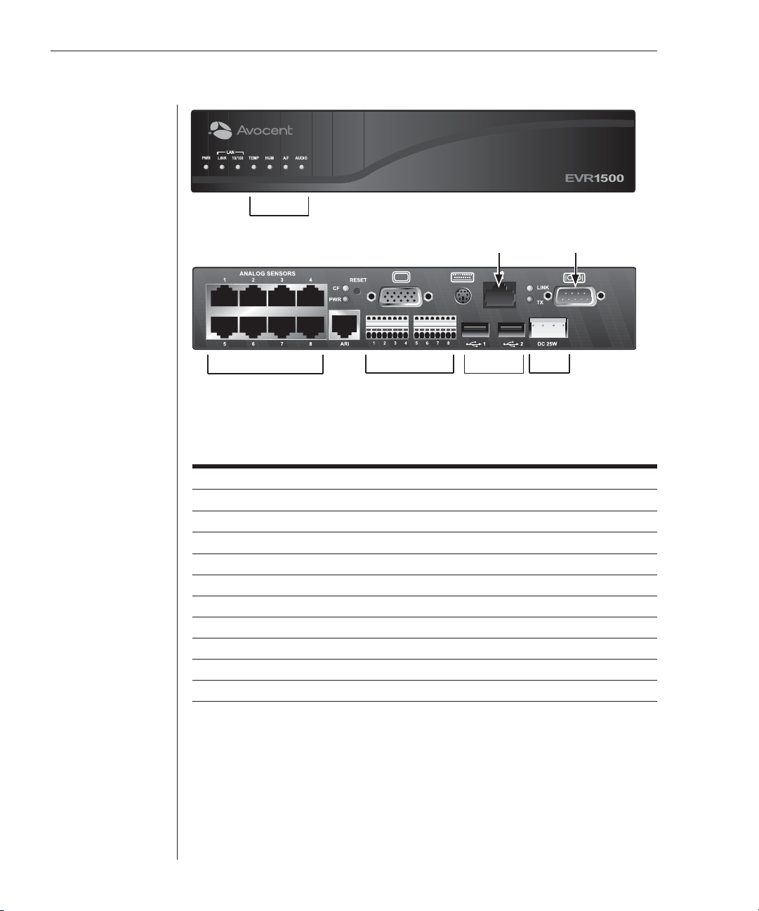
you to monitor precise locations within the rack or data center. See Figure 1.1
and the EVR1500 Environmental Monitor Appliance Features table for details.
Page 9
4 EVR1500 Installer/User Guide
Internal Sensors
Analog Sensors Digital Sensors
Figure 1.1: EVR1500 Environmental Monitor Appliance Front and Back Panel
Ethernet
Connection
USB Ports
Serial Port
DC Power
EVR1500 Environmental Monitor Appliance Features
Feature Description
Internal Sensors Four internal sensors (Temperature, Humidity, Air Flow, Audio)
Analog Sensors Eight inputs (RJ-45) with 12 VDC (Volts DC) powering
Digital Sensor Inputs Six, plug-in modules 1 to 6
Digital Sensor Outputs Two, plug-in modules 7 and 8
USB port 1 Reserved for future use
USB port 2 Reserved for future use
Serial port Used for confi guration
DC power connection For power supply (provided by Avocent)
ARI port Not in use
KVM console Not in use
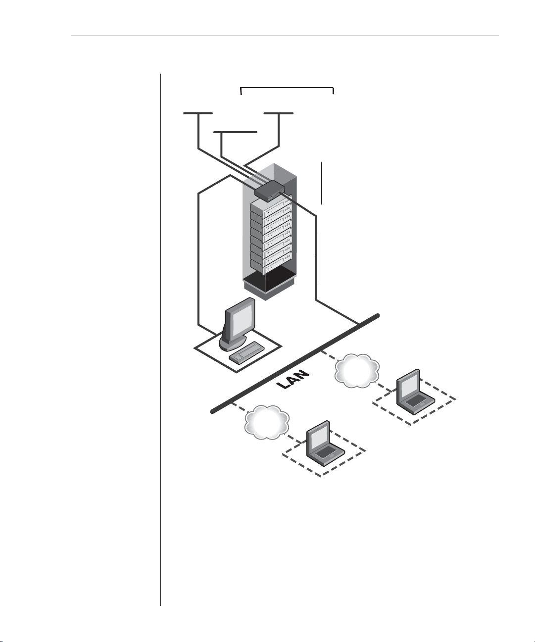
Typical Configuration
Shown in Figure 1.2, a typical configuration consists of the EVR1500
environmental monitor appliance, a serial connection for setup, an Ethernet
connection and a PC running Microsoft
DSView software.
®
Internet Explorer (IE) or Avocent
Page 10
Chapter 1: Product Overview 5
External Sensors
Analog Sensors
(up to eight)
Digital Outputs
(up to two)
Digital Inputs
(up to six)
Serial
Connection
Internal Sensors
• Temperature
• Humidity
• Air Flow
• Audio
TCP/IP
TCP/IP
Web GUI User
Figure 1.2: Typical EVR1500 Environmental Monitor Appliance Configuration
DSView Software
User
Safety Precautions
To avoid potential problems when using Avocent products, use only DC power
supplied by Avocent.
Page 11
6 EVR1500 Installer/User Guide
CAUTION: The EVR1500 environmental monitor appliance contains an internal battery that is
used for the real time clock. This battery is not a fi eld replaceable item, and replacement should
not be attempted by a user. If real time clock errors occur and the battery is suspected, visit the
Avocent web site at http://www.avocent.com/support or contact Avocent Technical Support at
(888) 793-8763.
NOTE: The AC power cord is the main disconnect.
Rack and wall mount safety considerations
• Elevated Ambient Temperature: If installed in a closed rack assembly, the
operation temperature of the rack environment may be greater than room
ambient. Use care not to exceed the rated maximum ambient temperature
of the appliance.
• Reduced Air Flow: Installation of the equipment in a rack should be such
that the amount of airfl ow required for safe operation of the equipment is
not compromised.
• Mechanical Loading: Mounting of the equipment in the rack should be such
that a hazardous condition is not achieved due to uneven mechanical loading.
• Circuit Overloading: Consideration should be given to the connection of
the equipment to the supply circuit and the effect that overloading of
circuits might have on overcurrent protection and supply wiring. Consider
equipment nameplate ratings for maximum current.
• Reliable Earthing: Reliable earthing of rack mounted equipment should be
maintained. Pay particular attention to supply connections other than
direct connections to the branch circuit (for example, use of power strips).
Page 12

2
Installation
Contents
Getting Started . . . . . . . . . . . . . . . . . . . . . . . . . . . . . . . . . . . . . . . . . . . . 9
Mounting the EVR1500 Environmental Monitor Appliance . . . . . . 11
Installing the EVR1500 Environmental Monitor Appliance . . . . . . 12
Configuring the EVR1500 Environmental Monitor Appliance . . . . 13
Page 13

Chapter 2: Installation 9
Chapter 2: Installation
Getting Started
Before installing your EVR1500 environmental monitor appliance, refer to the
following lists to ensure that you have all the items that shipped with the
appliance as well as other items necessary for proper installation.
Supplied with the EVR1500 environmental
monitor appliance
The following items are supplied with the EVR1500 environmental
monitor appliance:
• EVR1500 environmental monitor appliance
• One DC power supply
• One serial null modem cable (Avocent part number 042-0063)
• Wall mounting brackets and screws
• EVR1500 Installer/User Guide
• EVR1500 Quick Installation Guide
Additional items needed
For the mount shelf rack option, order the 1U Mount Shelf Rack kit (Avocent
part number 790200).
Hardware requirements
The following hardware requirements are necessary for a PC connecting to the
EVR1500 environmental monitor appliance:
• 300 MHz processor
• 128 Mb or more of DRAM (Dynamic Random Access Memory)
Software requirements
The following software requirements are necessary for a PC connecting to
the EVR1500 environmental monitor appliance:
• Microsoft
Professional SP1a
• J2SE™ Runtime Environment 1.4.2 or later
• Microsoft Internet Explorer (IE) 5.5 SP2 or IE 6 SP1
®
Windows® 2000 Professional SP3 or Microsoft Windows XP
Page 14

10 EVR1500 Installer/User Guide
NOTE: You can download the J2SE Runtime Environment from the Sun Microsystems™ web
site by typing http://java.sun.com/j2se/downloads.html in the web browser address bar.
If you do not have the J2SE Runtime Environment installed on your PC when you fi rst connect
to the EVR1500 environmental monitor appliance with a web browser, the appliance will
redirect your browser to the java.sun.com web site so that you can download and install the
correct J2SE Runtime Environment fi les on your PC.
CAUTION: Downloading the newest version of Java J2SE may affect other Java-accessible
devices. If devices are affected, check them for the most recent version of code.
Verification of Ethernet and sensor conditions
The LEDs on the front and back panels of the EVR1500 environmental monitor
appliance show the status of the appliance and the Ethernet connection. LEDs
on the front panel also indicate the status of the internal sensors. Refer to the
following table for descriptions of the LEDs on the EVR1500 environmental
monitor appliance.
Front Panel LEDs
LED Label Color Description
PWR Green When illuminated, indicates the appliance
LINK Green When illuminated, indicates an active
10/100 Amber When illuminated, indicates communication at
TEMP Green When illuminated green, temperature is normal.
HUM Green When illuminated green, humidity is normal.
A/F (Air Flow) Green
AUDIO Green When illuminated green, audio is normal.
is powered.
connection to the network.
the 100 Mb rate. When not illuminated, indicates
10 Mb rate.
Red When illuminated red, temperature is
over/under threshold.
Red When illuminated red, humidity is over/
under threshold.
When illuminated green, air fl ow is normal.
Red
over/under threshold.
Red
When illuminated red, air fl ow is
When illuminated red, audio is over/under threshold.
NOTE: TEMP, HUM, A/F and AUDIO LEDs are controlled by the GUI confi guration for each
specifi c sensor.
Page 15

Chapter 2: Installation 11
Back Panel LEDs
LED Label Color Description
CF (Compact FLASH) Amber Blinks to indicate activity to the Compact FLASH
PWR Green Illuminates to indicate the appliance is powered
LINK Green Illuminates to indicate an active connection
to the network
TX Amber Blinks to indicate network activity
Mounting the EVR1500 Environmental
Monitor Appliance
You can wall mount your EVR1500 environmental monitor appliance using
the supplied wall mounting kit. You also can rack mount your appliance on a
standard shelf or the 1U Rack Mount Shelf (supplied separately: Avocent part
number 790200) using the instructions provided with the kit. See Figure 2.1 for
the wall mounting option.
Figure 2.1: EVR1500 Environmental Monitor Appliance Wall Mounting Diagram
To wall mount the environmental monitor appliance:
1. Using the screws supplied with the wall mounting brackets, place the
brackets on the EVR1500 environmental monitor appliance.
2. While holding the appliance in the preferred mounting position, mark the
holes needed for the wall plugs.
NOTE: For proper operation of the internal sensors, mount the EVR1500 environmental
monitor appliance with the Avocent logo in the “up” position, as shown in Figure 2.1.
3. Install the wall plugs.
4. Install the EVR1500 environmental monitor appliance and fasten the
screws to hold the appliance in place.
Page 16
12 EVR1500 Installer/User Guide
Installing the EVR1500 Environmental
Monitor Appliance
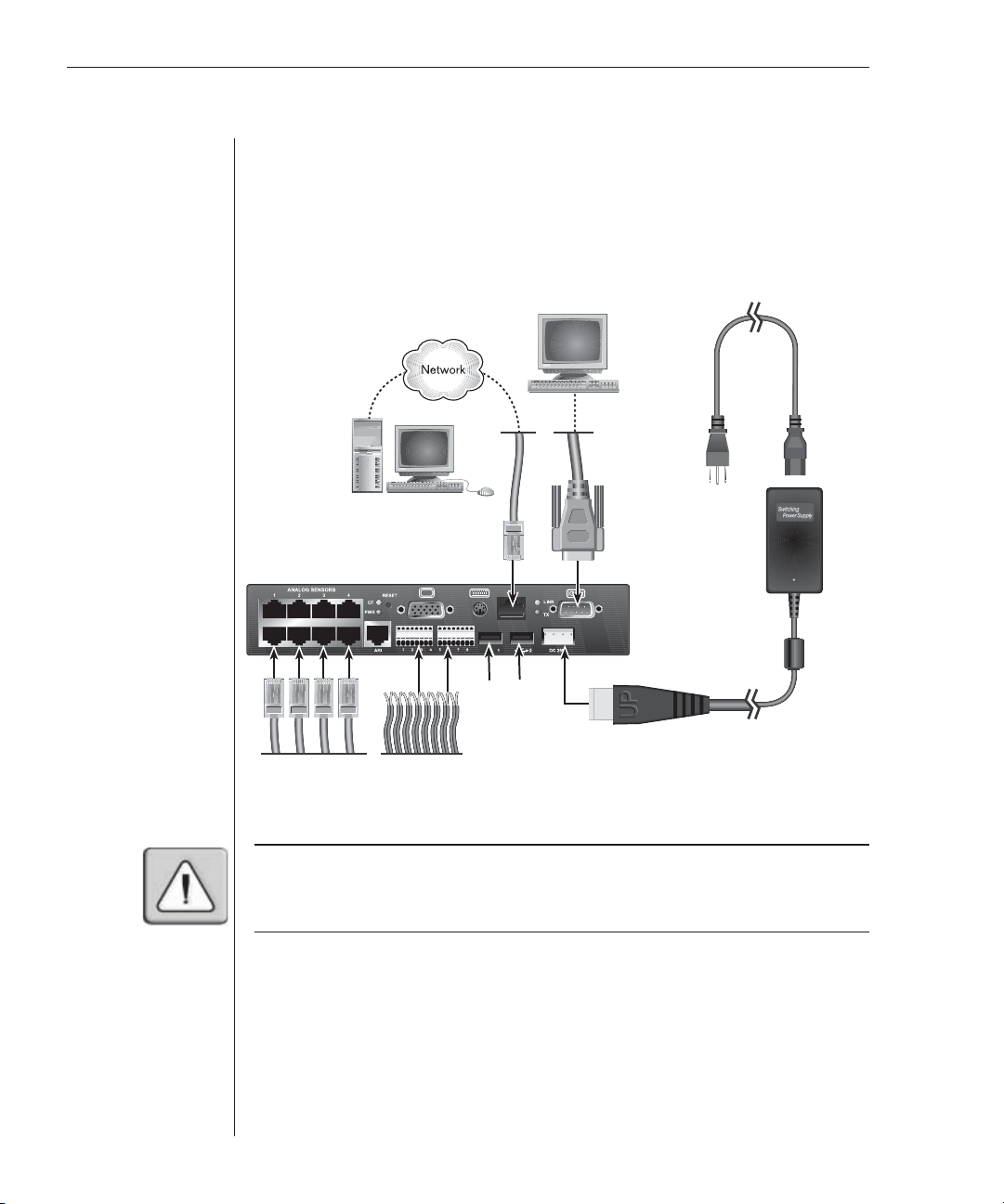
Figure 2.2 illustrates one possible configuration for your EVR1500
environmental monitor appliance. Follow the detailed set of procedures
following Figure 2.2 to successfully install the appliance.
AC Power Cord
DC Power
Module
Serial Port
USB Ports
Analog Sensors Digital Inputs/
Figure 2.2: Basic EVR1500 Environmental Monitor Appliance Configuration
WARNING: To reduce the risk of electric shock or damage to your equipment-
- Plug the power cord into a grounded (earthed) outlet that is easily accessible at all times.
- Disconnect the power from the appliance by unplugging the power cord from either the
electrical outlet or the DC power supply.
Outputs
To install the EVR1500 environmental monitor appliance:
1. Using an Unshielded Twisted Pair (UTP) CAT 5 cable, connect the
network port on the back of the EVR1500 environmental monitor
appliance to your LAN.
2. On the back of the appliance, under Analog Sensors, insert sensor cables
supplied by Avocent or a third party into any of the RJ-45 ports. Place the
sensor in the desired location. See Appendix C for pinout information.
Page 17

Chapter 2: Installation 13
3. On the back of the EVR1500 environmental monitor appliance, insert into
plug-in modules 1 to 6, 2-wire digital sensors supplied by Avocent or a
third party. Place the sensor in the desired location. See Appendix C for
pinout information.
NOTE: Plug-in modules 7 and 8 are digital output ports.
4. With the small white ridge of the power connector facing up, plug the
supplied power cord into the back of the EVR1500 environmental monitor
appliance. Connect the appliance by plugging one end of the AC power
cord into the switching power supply. Plug the other end of the power
cord into the appropriate AC power source.
5. When power is applied, the appliance performs a boot sequence for
approximately 60 seconds. After the boot sequence is complete, press the
Enter key to display the login prompt on the Terminal screen. To manually
set the IP address follow the instructions in the next section, Confi guring
the EVR1500 Environmental Monitor Appliance.
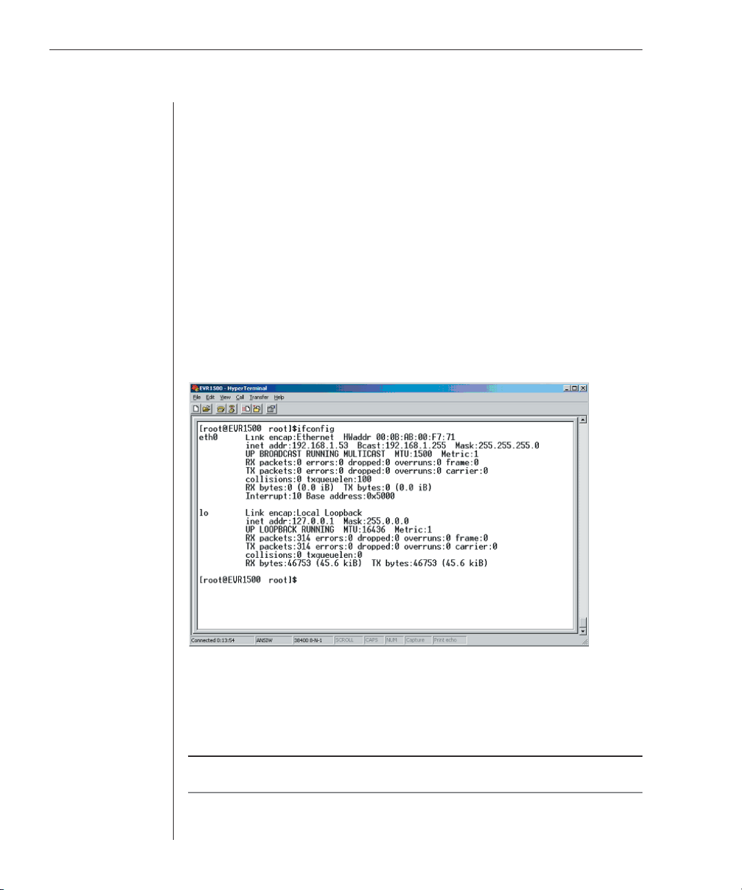
NOTE: The EVR1500 environmental monitor appliance is factory confi gured to use the DHCP
(Dynamic Host Confi guration Protocol) to obtain an IP address from the network. If your
appliance does not have a MAC address on the bottom of the appliance, you can obtain a MAC
address from the CLI (Command Line Interface) using the ifconfi g command as shown
in Figure 2.3.
6. Using Internet Explorer, launch the web GUI by typing the IP address
confi gured in the Confi guring the EVR1500 Environmental Monitor
Appliance section.
NOTE: You can download this application from the Sun Microsystems web site by typing
http://java.sun.com/j2se/downloads.html in the web browser address bar.
Once the IP address has been set through the Terminal screen, changes to the IP address can
be made through the web GUI. Refer to Confi guring the Network in Chapter 3 for instructions.
7. Finally, confi gure the sensors. Refer to Chapter 3 for instructions on
confi guring the sensors.
Configuring the EVR1500 Environmental
Monitor Appliance
The initial configuration of the EVR1500 environmental monitor appliance
must be performed using terminal emulation software (such as
HyperTerminal
through a terminal connection or through the web GUI. See Configuring the
Network in Chapter 3 for instructions on configuring the EVR1500
environmental monitor appliance through the web GUI.
®
). After the initial confi guration, you can make changes
Page 18
14 EVR1500 Installer/User Guide
To use a terminal or terminal emulation program:
1. After mounting the appliance, connect a terminal or PC running terminal
emulation software to the serial port on the back panel of the EVR1500
environmental monitor appliance using the supplied null modem cable.
Confi gure your terminal or terminal emulation program as follows:
Baud rate 38.4K
Bits per character 8 bits
Parity None
Stop bits 1 stop bit
Flow control None
2. On the Terminal screen, enter root as the default username and root as
the default password.
3. Verify the current IP address by entering ifconfi g. As shown in Figure 2.3,
the following default IP parameters display:
[IP ADDRESS] [NETMASK] [GATEWAY]
Figure 2.3: IP Parameter Summary
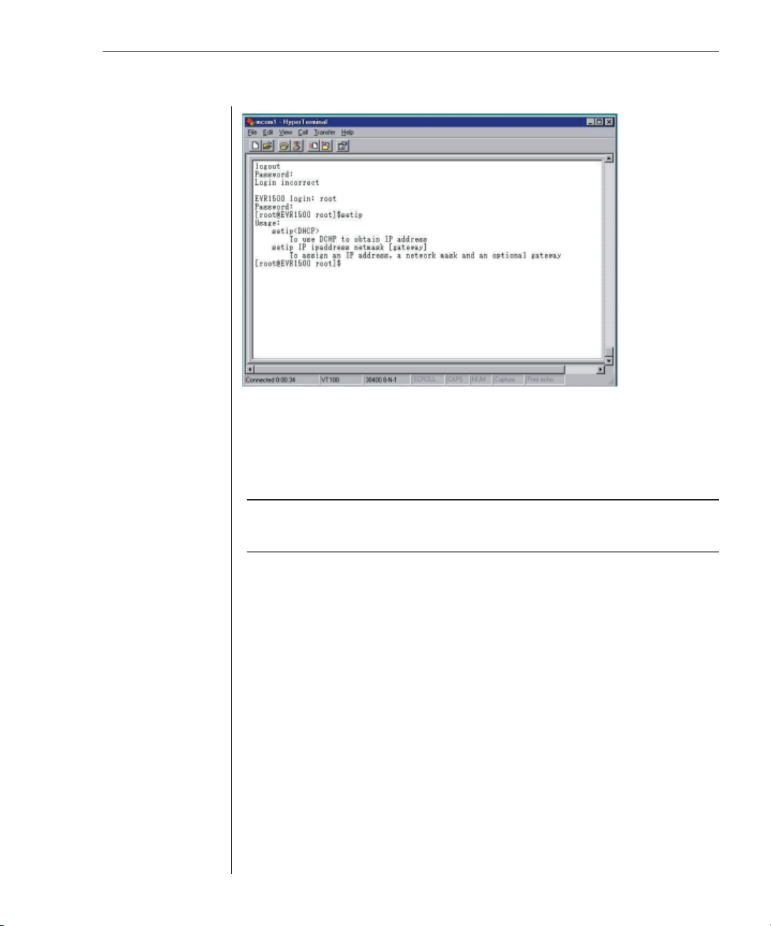
4. If you wish to change the IP address, enter setip on the Terminal screen.
The following setup options display, as shown in Figure 2.4:
setip DHCP
setip IP ipaddress netmask [gateway]
NOTE: Using DHCP enables you to obtain IP address and network confi guration. Gateway is
in brackets on the screen because it is optional.
Page 19
Chapter 2: Installation 15
Figure 2.4: IP Parameter Setup
5. Obtain the IP address through DHCP by entering setip DHCP.
- or Enter static IP parameters, using the following as an example:
setip IP 192.168.1.53 (space) 255.255.255.0 (space) 192.168.1.1
NOTE: For the DHCP server reservation, locate the MAC address on the bottom of the
EVR1500 environmental monitor appliance or on the IP Parameter Summary window displayed
as HWaddr in Figure 2.3.
6. Reboot the EVR1500 environmental monitor appliance by entering reboot
on the Terminal screen.
7. After you have rebooted the appliance, at the login prompt, enter root as
the username and root as the password.
8. Verify the new IP parameters by entering ifconfi g. The IP parameters are
displayed as shown in Figure 2.3.
9. Log out of the Terminal screen by entering logout.
Page 20

16 EVR Installer/User Guide
Page 21

3
Basic Operations
Contents
Launching the Web Browser GUI . . . . . . . . . . . . . . . . . . . . . . . . . . . . 19
Launching Through DSView Software . . . . . . . . . . . . . . . . . . . . . . . 20
Configuring the Network . . . . . . . . . . . . . . . . . . . . . . . . . . . . . . . . . . 21
Configuring the Email Server . . . . . . . . . . . . . . . . . . . . . . . . . . . . . . . 23
Setting the Clock . . . . . . . . . . . . . . . . . . . . . . . . . . . . . . . . . . . . . . . . . 24
Changing the Login Password . . . . . . . . . . . . . . . . . . . . . . . . . . . . . . 25
Configuring Digital Inputs . . . . . . . . . . . . . . . . . . . . . . . . . . . . . . . . . 26
Configuring Analog Inputs and Internal Sensors . . . . . . . . . . . . . . . . . . .27
Configuring Digital Outputs . . . . . . . . . . . . . . . . . . . . . . . . . . . . . . . . 29
Configuring Calculations . . . . . . . . . . . . . . . . . . . . . . . . . . . . . . . . . . 31
Configuring XML Reports . . . . . . . . . . . . . . . . . . . . . . . . . . . . . . . . . 33
Configuring Delimited Reports . . . . . . . . . . . . . . . . . . . . . . . . . . . . . . 35
Configuring User Reports . . . . . . . . . . . . . . . . . . . . . . . . . . . . . . . . . . 36
Configuring Email Actions . . . . . . . . . . . . . . . . . . . . . . . . . . . . . . . . . 38
Configuring SNMP Traps . . . . . . . . . . . . . . . . . . . . . . . . . . . . . . . . . . 40
Configuring FTP Actions . . . . . . . . . . . . . . . . . . . . . . . . . . . . . . . . . . 42
Configuring Combination Actions . . . . . . . . . . . . . . . . . . . . . . . . . . . 44
Configuring Output Actions . . . . . . . . . . . . . . . . . . . . . . . . . . . . . . . . 46
Configuring Report To File Actions . . . . . . . . . . . . . . . . . . . . . . . . . . 47
Viewing Logs . . . . . . . . . . . . . . . . . . . . . . . . . . . . . . . . . . . . . . . . . . . . 49
Page 22
Chapter 3: Basic Operations 19
Chapter 3: Basic Operations
The operating platform for the EVR1500 environmental monitor appliance
uses the Linux
application. The web application requires the Java J2SE Runtime Environment
(1.4.2 or later) for system configuration, application setup and data
presentation. The Java applet is installed on your PC from the EVR1500
environmental monitor appliance when you type the appropriate URL in the
web browser address field.
Launching the Web Browser GUI
After you have installed the EVR1500 environmental monitor appliance, you
are ready to launch the web application’s GUI. The web GUI provides you with
easy-to-navigate screens for configuring the network, sensor inputs /outputs
(I/O) and actions (such as email) that will perform alarm reporting.
To launch the web GUI:
1. If the J2SE Runtime Environment (1.4.2 or later) is not running on your
computer, load the applet from the Sun Microsystems web site by typing
the following URL in the web browser address bar:
http://java.sun.com/J2se/downloads.html
®
2.4 kernel and is configured through a web browser
2. From the Sun Microsystems web page, download the J2SE Runtime
Environment (1.4.2 or later). Once the fi le is downloaded, install it on your
computer and reboot.
3. Launch Internet Explorer and type the appropriate URL in the web
browser address fi eld. (For example, if your EVR1500 environmental
monitor appliance has the IP address 192.168.1.53, type http://192.168.1.53
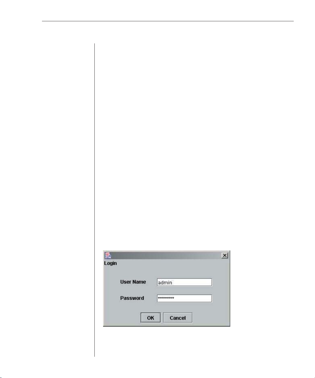
in the web browser address fi eld.) This action loads the Java applet. The
Login window displays.
Figure 3.1: Login Window
4. Type admin in the User Name fi eld.
5. Type password in the Password fi eld. Click OK.
Page 23
20 EVR1500 Installer/User Guide
NOTE: A password can be changed by selecting the User or System tab from the web GUI
and typing a new password in the Password fi eld.
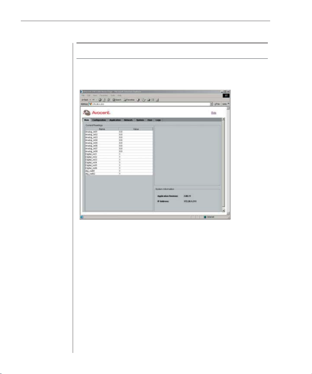
6. The Main tab window displays a summary of all enabled digital and
analog I/Os in addition to calculation values. This window also displays
general system information.
Figure 3.2: Main Tab
Launching Through DSView Software
You can launch the EVR1500 environmental monitor appliance through the
Avocent DSView software if you are running the application on your system
and the EVR1500 environmental monitor appliance has been added through
the DSAdmin management application. For more information on adding and
viewing the EVR1500 environmental monitor appliance through the DSView
software (2.1 or later), refer to the DSView Installer/User Guide.
To launch through DSView software:
1. Add the EVR1500 environmental monitor appliance using the DSAdmin
management application.
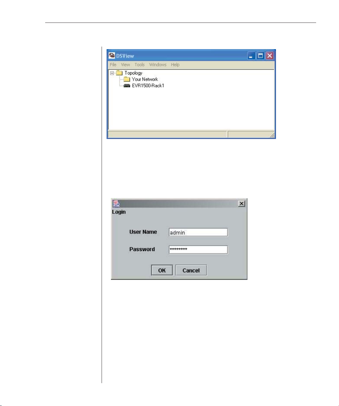
2. Launch the DSView software. The DSView software window displays.
Page 24
Chapter 3: Basic Operations 21
Figure 3.3: DSView Software Window
3. Double-click the To pology icon. The EVR1500 environmental monitor
appliance icon displays.
4. Double-click the EVR1500 environmental monitor appliance icon. Internet
Explorer is launched and the Login window displays. This action loads
the Java applet.
Figure 3.4: Login Window
5. Type admin in the User Name fi eld.
6. Type password in the Password fi eld. Click OK.
Configuring the Network
You can configure the network and set parameters for the SMTP (Simple Mail
Transfer Protocol) email server through the web GUI Network tab. If you have
already configured your network through HyperTerminal, the values will be
automatically populated; you can bypass the following steps provided and
proceed to Configuring the Email Server.
Page 25

22 EVR1500 Installer/User Guide
To confi gure the network:
1. After launching the web GUI, click Network - Fixed Network. The Fixed
Network Preferences window displays a list of confi guration items for the
Ethernet. Your IP address and network settings will display. If you have an
IP address assigned by DHCP, only the IP address will display.
Figure 3.5: Fixed Network Preferences Window
2. Set the EVR1500 environmental monitor appliance for DHCP operation by
selecting the Automatic (DHCP) button. Proceed to step 4 to obtain a
DHCP address by saving the confi guration and resetting the appliance.
- or Set the EVR1500 environmental monitor appliance for manual operation
by selecting the Manual button. If you have used HyperTerminal to
confi gure the network, the Manual button is selected, and the IP Address,
Subnet Mask and Default Gateway fi elds will display appropriate values. If
desired, change the values in the fi elds. Proceed to step 3.
3. Type the primary and secondary DNS IP address in the Primary and
Secondary fi elds respectively.
4. Click the Save button to save the confi guration.
- or Click the Cancel button to revert all confi guration items in the Network tab
to the last Save operation.
5. Reboot the EVR1500 environmental monitor appliance by selecting
System - Application Update. Click Restart.
Page 26

Chapter 3: Basic Operations 23
Configuring the Email Server
You can set parameters for the SMTP email server address through the web
GUI Network tab.
NOTE: Confi guring the email server is necessary only if you wish to send alert notifi cations
through email. If you do not intend to use email alerts, you may skip the following instructions.
To confi gure the email server address:
1. After launching the web GUI, click Network - Email Preferences. The Email
Preferences window displays the confi guration items for setting
email preferences.
2. Type the URL or the IP address for the email server in the SMTP
Server fi eld.
Figure 3.6: Email Preferences Window
NOTE: The SMTP server can be an Internet name (www.yourmailserver.com) or an IP address
(192.168.1.1). Consult your email administrator for appropriate values for these fi elds.
3. In the Server Port fi eld, type the number of the email port on the
SMTP Server.
4. In the From Address fi eld, type the email address that will be used in the
From address in the email actions.
Page 27

24 EVR1500 Installer/User Guide
5. Click the Save button to save the settings for your email confi guration.
- or Click the Cancel button to revert all confi guration items in the Network tab
to the last Save operation.
Setting the Clock
After configuring the network and/or the email server, set the network
system time.
To set the clock:
NOTE: The time zone shown on the terminal emulation screen is in Greenwich Mean Time
(GMT). The web GUI is set to the Windows time and date settings.
1. After launching the web GUI, click System - Set Clock. A window displays
confi gurable items for the clock.
Figure 3.7: Set Clock Window
2. Type the current time in the Hours, Minutes and Seconds fi elds. For the
Hours entry, type a value from Ø to 23. Type the current date in the Month,
Day and Year fi elds. For the Year entry, type a value greater than 2000.
NOTE: Message boxes will display if values are out of range.
3. Click Set to save the clock settings.
Page 28

Chapter 3: Basic Operations 25
4. Click Refresh to update the display.
5. Click Restart to ensure correct confi guration on the EVR1500
environmental monitor appliance.
Changing the Login Password
Using the Change Password feature, you can change your login password
multiple times during your web session.
Figure 3.8: Change Password Window
To change your password:
1. After launching the web GUI, click User - Change Password. A window
displays editable fi elds for changing your password.
2. Type your old password in the Old Password fi eld.
3. Type your new password in the New Password fi eld.
4. Retype your new password in the Retype New Password fi eld.
5. Click Set to save the new password.
Page 29

26 EVR1500 Installer/User Guide
Configuring Digital Inputs
After installing the EVR1500 environmental monitor appliance and configuring
the network, you can view digital sensor channels and values for each digital
input in the system. From the Digital Inputs window, you can also rename
digital inputs.
To confi gure digital inputs:
1. After launching the web GUI, click Confi guration - Digital Inputs. The
Digital Inputs window displays the list of the system’s digital inputs.
NOTE: The Channel column is fi xed and is the internal representation of the input.
2. Click the row containing the digital sensor input you wish to confi gure.
The sensor input information displays in the dialog box.
Figure 3.9: Digital Inputs Window
NOTE: In Figure 3.9, the last two digits in the sensor’s default name represent the port
connecting the sensor to the EVR1500 environmental monitor appliance. It is good practice to
use this format when naming sensors.
3. Click the Enabled checkbox to enable the selected digital input.
NOTE: An enabled digital input will display in the Main tab window and will be available for use
in the following operations: Calculations, SNMP actions, Output actions, Thresholds, Rules,
Timed Rules and Reports.
Page 30

Chapter 3: Basic Operations 27
4. If desired, edit the existing name of the digital input by clicking in the
Unique name fi eld and typing a new name. The name cannot contain any
spaces. The only special character allowed is the underscore (_).
5. If desired, set the threshold for the digital input by clicking Application Thresholds. For instructions, refer to Setting Thresholds in Chapter 4.
6. Click Save to save the changes made to the digital input(s).
- or Click Cancel to cancel the updates. Canceling displays the last saved value
for the digital input in the Current Value cell for the entire tab.
Configuring Analog Inputs and Internal Sensors
After installing the EVR1500 environmental monitor appliance and configuring
the network, you can configure, rename and test analog inputs and internal
sensors through the Configuration tab window. Before configuring analog
input sensors, be sure you have the necessary information, including input
voltage range and convert value range. Typically, each analog sensor is
shipped with the sensor’s input voltage range and a conversion table showing
the actual values interpreted from the voltages. For example, a temperature
sensor might have a voltage range of Ø to 5 volts with a conversion range of 5
degrees F (Farenheit) to 140 degrees F.
To confi gure analog inputs and internal sensors:
1. After launching the web GUI, click Confi guration - Analog Inputs. The
Analog Inputs table lists eight inputs, corresponding to the eight RJ-45
connectors on the back of the appliance. Also displayed are the four
internal sensors (Temperature, Humidity, Air Flow and Audio) at the
bottom of the table.
2. Click the row containing the analog input you wish to confi gure. The
analog input information displays in the dialog box.
NOTE: In Figure 3.10, the last two digits in the sensor’s default name represent the port
connecting the sensor. It is good practice to use this format when naming sensors.
Page 31

28 EVR1500 Installer/User Guide
Figure 3.10: Analog Inputs Window
3. Click the Enabled checkbox to enable the analog sensor input.
NOTE: An enabled analog input will display in the Main tab window and will be available for use
in the following operations: Calculations, SNMP actions, Output actions, Thresholds, Rules,
Timed Rules and Reports.
4. If desired, edit the name of the analog input by typing a new name in the
Unique name fi eld. The name cannot contain any spaces. The only special
character allowed is the underscore (_).
5. Type the minimum voltage input range (for example, Ø, 1 or 2 volts) in the
Raw minimum value fi eld. This range is the minimum DC voltage range
output from the sensor.
6. Type the maximum voltage input range (for example, 5 or 10 volts) in the
Raw maximum value fi eld. This value is the maximum DC voltage range
output from the sensor.
7. Type the analog input’s converted minimum value (for example, -40
degrees F) in the Converted minimum value fi eld.
8. Type the analog input’s converted maximum value (for example, 85
degrees F) in the Converted maximum value fi eld.
NOTE: Values for steps 5 to 8 are provided with the analog sensor documentation.
Page 32

Chapter 3: Basic Operations 29
NOTE: The two fi elds, Converted minimum value and Converted maximum value, enable you
to input a conversion range used to mathematically convert an input value from its input range
to the conversion range. The EVR1500 environmental monitor provides linear conversion
between these values. For example, for a temperature probe with a range of Ø to 5 VDC and
a conversion range of - 40 to 85 degrees C (Celsius), 1 VDC would be equal to -40 degrees C
and 5 VDC would be equal to +85 degrees C.
9. In the Units for converted value fi eld, type the unit you wish to display
with the value (for example, degrees F or degrees C).
10. Click Save to save the changes made to the analog input(s) and all other
items in the Confi guration tab.
- or Click the Cancel button to revert all confi guration items in the
Confi guration tab to the last Save operation.
Configuring Digital Outputs
After installing the EVR1500 environmental monitor appliance and configuring
the network, you can configure and rename two digital outputs (plug-in
modules 7 and 8) through the Configuration tab interface.
The front panel LEDs (Audio_LED, Air_Flow_LED, Humidity_LED,
Temperature_LED) also display in the Digital Outputs window and are
defaulted to green [Current Value = 1 (green) or Ø (red)]. Refer to Setting
Thresholds and Configuring Rules in Chapter 4 for instructions on configuring
the front panel LEDs.
NOTE: The Heater_Control digital output is used to eliminate excessive condensation from the
internal humidity sensor. The default value is Ø or Off. Setting the value to 1 or On for 30 to 60
seconds eliminates condensation.
Page 33

30 EVR1500 Installer/User Guide
Figure 3.11: Digital Outputs Window
To confi gure digital outputs:
1. After launching the web GUI, click Confi guration - Digital Outputs. The
Digital Outputs window displays a list of the digital sensor outputs.
NOTE: The Channel column is not editable and is the internal representation of the input.
2. Click the row containing the digital sensor you wish to confi gure or test.
The sensor output information displays in the dialog box.
3. Click the Enabled checkbox to enable the digital output.
NOTE: An enabled digital output will be displayed on the Main tab. Enabling a digital output
also makes it available for use in the following operations: Calculations, SNMP actions, Output
actions, Thresholds, Rules, Timed Rules and Reports.
4. If desired, edit the name of the digital output by clicking in the Unique
name fi eld and typing a new name. The name cannot contain any spaces.
The only special character allowed is the underscore (_).
5. Click the Test Selected button. The Output Value box displays, enabling you
to set the digital output.
6. Type a value that will be applied to the output channel. Click OK. This value
will become the digital output’s button label. Valid settings are 1 (1 = on) or
Ø (Ø = off).
Page 34

Chapter 3: Basic Operations 31
NOTE: Clicking the Test S el ected button does not save the new value.
7. Click the Save button to save changes to the digital output(s) and all other
items in the Confi guration tab.
- or Click the Cancel button to revert all confi guration items in the
Confi guration tab to the last Save operation.
Configuring Calculations
The Calculations feature enables you to configure an equation and the units
used to calculate digital and analog I/O. This feature also enables you to create
new calculations or delete existing calculations.
Figure 3.12: Calculations Window
To confi gure calculations:
1. After launching the web GUI, click Confi guration - Calculations. The
Calculations window displays.
2. Edit an existing calculation by clicking the row containing the calculation.
-or Click the Create New button to add a calculation. A new row is added to
the Calculations list.
The calculation information displays in the dialog box.
Page 35

32 EVR1500 Installer/User Guide
3. Click the Enabled checkbox to enable the calculation.
NOTE: An enabled calculation is available for use in the following operations: SNMP actions,
Output actions, Thresholds, Rules, Timed Rules and Reports.
4. Type a unique name for the calculation in the Unique name fi eld. The
name cannot contain any spaces. The only special character allowed is
the underscore (_).
5. Type the equation for the calculation in the Calculation fi eld using the
format shown in the following example:
Temp_average=($temp1+$temp2+$temp3)/3
NOTE: Use numbers, arithmetic operators, logic operators and named items from the
application. Named items are digital inputs, digital outputs, analog inputs and other
calculations as shown in Figure 3.12. These items are referenced using their name (for
example, $temp1) and are preceded with a dollar sign. For example, if analog input Ø is named
ana_inØØ in the Analog Input confi guration, it can be referenced in an equation as $ ana_inØØ.
6. Type the units for the calculation in the Display units fi eld.
NOTE: The fi eld, Display units, requires a string value that is displayed with the result of the
equation. It is not interpreted or used to affect the value. For example, in Figure 3.12, the
Current Value fi eld contains the display unit Deg C, also shown in the Display unit fi eld.
If appropriate values are not entered, a message box displays a list of available
operands. The EVR1500 environmental monitor appliance uses standard C
programming language operators and functions. Refer to the following table
for the allowed operators and functions.
Language Operators and Functions
Operators Description
Arithmetic +, -, *, /
Compare ==, !=, ,=, <, >=. >
Logical && , ||
Functions abs, acos, asin, atan, ceil, cos, exp, floor, log, round,
sin, sqrt, tan, atan2, max, min, pow, random, counter
7. After typing the calculation equation and units, click the Test Selected
button to perform the calculation. This button must be clicked to refresh
the value.
8. A message box displays the new calculation. Click OK to exit the
message box.
NOTE: Clicking the Test S elected button does not save the confi guration change.
9. Click the Save button to save all of the items in the Confi guration tab.
Page 36

Chapter 3: Basic Operations 33
- or Click the Cancel button to revert all confi guration items in the
Confi guration tab to the last Save operation.
To delete a calculation:
1. After launching the web GUI, click Confi guration - Calculations. The
Calculations window displays a list of confi gured calculations.
2. Click the row containing the calculation you want to delete.
3. Click the Delete Selected button.
4. Click the Save button to save the change.
Configuring XML Reports
The EVR1500 environmental monitor appliance enables you to generate and
send XML reports as email or through FTP. XML reports display sensor I/O
values encapsulated in XML format and can be attached directly to an email.
Before sending an XML report through FTP, you must write the data to a file
using the Report to File action. Using the XML Reports feature, you also can
edit, test and delete existing reports.
Figure 3.13: XML Reports Window
Page 37

34 EVR1500 Installer/User Guide
To confi gure an XML report:
1. After launching the web GUI, click Confi guration - XML Reports. The XML
Reports window displays XML reports confi gured in the system. A list of
named sensor values that you can include in an XML report also displays.
NOTE: Enabled reports will display in drop- down menu selections and will be available for use
in the following operations: Report to File and Email actions.
2. Click the name of the XML report you want to edit.
- or Click the Create New button to create a new report. A new row is added to
the XML Reports table.
The XML report information displays in the dialog box.
3. Click the Enabled checkbox to enable the XML report.
4. Type a new name for the report in the Unique name fi eld. The name
cannot contain any spaces. The only special character allowed is
the underscore (_).
5. Type header information for the XML report in the Header fi eld.
6. In the Values table, click the checkboxes to enable the sensor values you
wish to include in the XML report.
NOTE: Click Check All or Clear All to select or deselect all sensor values for the report.
7. Click the Test Selected button to test the report. A message box displays to
show the contents of the report you are testing. Click OK to exit the
message box.
NOTE: Clicking the Test Selected button does not save the confi guration change.
8. Click Save to save all of the confi guration items in the Confi guration tab.
- or Click the Cancel button to revert all confi guration items in the
Confi guration tab to the last Save operation.
To delete an XML report:
1. After launching the web GUI, click Confi guration - XML Reports. The
XML Reports window displays the XML reports confi gured in the system.
2. Click the row containing the XML report you wish to delete.
3. Click the Delete Selected button to delete the report.
4. Click Save to save the change.
Page 38

Chapter 3: Basic Operations 35
Configuring Delimited Reports
The EVR1500 environmental monitor appliance enables you to generate and
send delimited reports as email or through FTP. Delimited reports contain
user-defi ned delimiters that separate sensor data and can be written to
spreadsheets or other documents. Before sending a delimited report through
FTP, you must write the data to a file using the Report to File action. Using the
Delimited Reports feature, you also can edit, test and delete existing
delimited reports.
Figure 3.14: Delimited Reports
To confi gure a delimited report:
1. After launching the web GUI, click Confi guration - Delimited Reports. The
Delimited Reports window displays a list of confi gured delimited reports
and a list of sensor values that you can include in a delimited report.
NOTE: Enabled reports will display in drop- down menu selections and will be available for use
in Report to File and Email actions.
2. Click the name of the delimited report you want to edit.
- or Click the Create New button to add a new report. A new row is added to
the Delimited Reports table.
The delimited report information displays in the dialog box.
Page 39

36 EVR1500 Installer/User Guide
3. Click the Enabled checkbox to enable the delimited report.
4. Type a new name for the report in the Unique name fi eld. The name
cannot contain any spaces. The only special character allowed is
the underscore (_).
5. Type a delimiter in the Delimiter fi eld. Any delimiter, including colon (:),
semicolon (;), comma (,), plus (+), equals (=) and minus (-), may be used.
6. Type header information for the delimited report in the Header fi eld. The
values available for inclusion in the report display in the Values table.
7. Under Selected, click the checkboxes to select sensor values you wish to
include in the report.
NOTE: Click Check All or Clear All to select or deselect all sensor values for the report.
8. Click the Test Selected button to test the report. A message box displays to
show the contents of the report you are testing. Click OK to exit the
message box.
NOTE: Clicking the Test S el ected button does not save the confi guration change.
9. Click Save to save all of the confi guration changes in the Confi guration tab.
- or Click the Cancel button to revert all confi guration items in the
Confi guration tab to the last Save operation.
To delete a delimited report:
1. After launching the web GUI, click Confi guration - Delimited Reports. The
Delimited Reports window displays a list of confi gured delimited reports.
2. Click the row containing the delimited report you wish to delete.
3. Click the Delete button to delete the report.
4. Click the Save button to save the change.
Configuring User Reports
Using the EVR1500 environmental monitor appliance, you can generate and
send user reports as email or through FTP. User reports can be configured as
“free form” reports to meet your specific requirements and can be attached
directly to an email. Before sending a user report through FTP, you must write
the data to a file using the Report to File action. Using the User Reports feature,
you also can edit, test and delete existing user reports.
To confi gure a user report:
1. After launching the web GUI, click Confi guration - User Reports. The User
Reports window displays the user reports confi gured in the system.
Page 40

Chapter 3: Basic Operations 37
Figure 3.15: User Reports Window
2. Click the name of the user report you want to edit.
- or Click the Create New button to add a new user report. A new row is added
to the User Reports table.
The user report information displays in the dialog box.
3. Click the Enabled checkbox to enable the user report.
4. Type a new name for the user report in the Unique name fi eld. The name
cannot contain any spaces and the only special character allowed is the
underscore (_).
5. Type information for the user report you wish to create in the User Report
Script fi eld. Make sure that you type values that are enabled and valid.
Precede each value with a dollar sign ($), for example, $Analog_Input1.
NOTE: The User Report Script is a free -form fi eld. The text typed into the User Report Script
fi e l d w i l l be inserted into the user report exactly as you type it.
6. Click the Test Selected button to test the report. A message box displays the
contents of the report you are testing. Click OK to exit the message box.
See Figure 3.16 for an example of a user report.
Page 41

38 EVR1500 Installer/User Guide
Figure 3.16: User Report
NOTE: Clicking the Test S el ected button does not save the confi guration change.
7. Click the Save button to save the changes in the Confi guration tab.
- or Click the Cancel button to revert all confi guration items in the
Confi guration tab to the last Save operation.
To delete a user report:
1. After launching the web GUI, click Confi guration - User Reports. The User
Reports window displays a list of confi gured user reports.
2. Click the row containing the user report you wish to delete.
3. Click the Delete Selected button to delete the report.
4. Click the Save button to save the change.
Configuring Email Actions
After you have created a report, you can configure an email action to send
your report through email. The report will be displayed as the body of the
email. Using the Email feature, you also can edit, test and delete an existing
email action. You can configure up to 25 email actions.
NOTE: You must confi gure your email preferences before you can use the Email feature. Refer
to Confi guring the Email Server in this chapter for instructions.
Page 42

Chapter 3: Basic Operations 39
To confi gure an email action:
1. After launching the web GUI, click Confi guration - Email. The Email
window displays a list of existing email actions confi gured in the system.
Figure 3.17: Email Window
2. Click the row displaying the email action you want to edit.
- or Click the Create New button to add a new email action. A new row is
added to the Email table.
The email action information displays in the dialog box.
3. Click the Enabled checkbox to enable the email action.
NOTE: An enabled email action is available for use in the following operations: Combination
actions, Thresholds, Rules and Timed Rules.
4. Type a new name for the email action in the Unique name fi eld. The name
cannot contain any spaces, and the only special character allowed is
the underscore (_).
5. Type the recipient’s email address in the Address to send to fi eld. Only one
email address is allowed per entry.
6. Type the subject of the email message in the Subject of the message fi eld.
Page 43

40 EVR1500 Installer/User Guide
7. If you wish to include a report as an attachment to the email message,
select the report from the drop-down menu labeled Report to include.
Selecting a report is optional.
NOTE: The reports displaying in the drop-down menu are enabled XML, delimited and
user reports. The selected report is used as the body of the email when it is sent.
8. Click the Test Selected button to process the report, if applicable, and
send the email with the selected report. Once the action is completed,
a message box displays the status of the email being sent and any
issues related to the report.
NOTE: The SMTP server is used to send the email. The From email address is confi gured
by selecting Network - Email.
9. Click the Save button to save all confi guration changes in the
Confi guration tab.
- or Click the Cancel button to revert all confi guration items in the
Confi guration tab to the last Save operation.
To delete an email action:
1. After launching the web GUI, click Confi guration - Email. The Email
window displays a list of existing email actions confi gured in the system.
2. Click the row containing the email action you want to delete.
3. Click the Delete Selected button to delete the email action in the
selected row.
4. Click the Save button to save the change.
Configuring SNMP Traps
The SNMP Traps feature monitors and reports alarm conditions on internal
or external sensors. You can enable pre-configured traps or develop new
trap definitions, which the system uses as actions. Using the SNMP Traps
feature, you can also edit, test and delete existing traps.
Page 44

Chapter 3: Basic Operations 41
To confi gure an SNMP trap:
1. After launching the web GUI, click Confi guration - SNMP Traps. The
SNMP Traps window displays a list of pre-confi gured traps.
Figure 3.18: SNMP Traps Window
2. Click the name of the trap you wish to edit.
- or Click the Create New button to add a new trap. A new row is added to the
SNMP Traps table.
The trap information displays in the dialog box.
3. Click the Enabled checkbox to enable the trap.
NOTE: An enabled SNMP trap is available for use in the following operations: Combination
actions, Thresholds, Rules and Timed Rules.
4. Type a new name for the trap in the Unique name fi eld. The name cannot
contain any spaces, and the only special character allowed is
the underscore (_).
5. Type the address of the Network Management System (NMS) or the trap
collection system in the Manager host or IP (trap collection) fi eld. The
EVR1500 environmental monitor appliance will send the traps to
these locations.
6. Type a port number for the NMS or trap collection system in the Port on
the manager fi eld.
Page 45

42 EVR1500 Installer/User Guide
7. F or a new trap, type a unique OID (Object Identifi er) in the OID fi eld. If
the trap is notifying of a high threshold, use the following OID:
1.3.6.1.4.1.10 418.5 .1.1.9
- or If the trap is notifying a low threshold, use the following OID:
1.3.6.11.5.1.10418. 5.1.1.10
NOTE: These values conform to the EVR1500 environmental monitor appliance Trap
MIB (Management Information Base) described in Appendix D. You m ay also visit
www.avocent.com/support for the EVR1500 environmental monitor appliance trap MIB.
The OIDs for pre-confi gured traps will display in the drop-down menu
when you select the trap from the SNMP Traps list.
8. Select a value from the Value to report drop-down menu. The drop-down
menu displays all applicable enabled items.
NOTE: The value to report can be an internal sensor, analog input, digital input or calculation
that is reported in the trap to the NMS or trap collector.
9. Click the Test Selected button to test the trap. A message box displays the
status of the trap you are testing. Click OK to exit the message box.
NOTE: Clicking the Test S el ected button does not save the confi guration change.
10. Click the Save button to save the confi guration items in the
Confi guration tab.
- or Click the Cancel button to revert all confi guration items in the
Confi guration tab to the last Save operation.
To delete an SNMP trap:
1. After launching the web GUI, click Confi guration - SNMP Traps. The
SNMP Traps window displays a list of confi gured traps.
2. Click the row containing the trap you wish to delete.
3. Click the Delete Selected button to delete the trap.
4. Click the Save button to save the change.
Configuring FTP Actions
After you have created a report and converted it to a file using the Report to
File action, you can configure FTP actions to send your file through FTP. Using
the FTP feature, you also can edit, test and delete an existing FTP action. You
can configure up to 25 FTP actions. For details on the Report to File action,
refer to Configuring Report to File Actions in this chapter.
Page 46

Chapter 3: Basic Operations 43
To confi gure an FTP action:
1. After launching the web GUI, click Confi guration - FTP. The FTP window
displays a list of existing FTP actions confi gured in the system.
Figure 3.19: FTP Window
2. Click the row containing the FTP action you wish to edit.
-orClick the Create New button to add a new FTP action. A new row is added
to the FTP table.
The FTP information displays in the dialog box.
3. Click Enabled to enable the FTP action.
NOTE: An enabled FTP action is available for use in the following operations: Combination
actions, Thresholds, Rules and Timed Rules.
4. Type a new name for the FTP action in the Unique name fi eld. The name
cannot contain any spaces, and the only special character allowed is
the underscore (_).
5. Select a fi le from the File to Send drop-down menu. The fi le you select will
be sent to the server by the FTP action. After the fi le is sent, the FTP action
deletes the fi le.
NOTE: Unsuccessful FTP actions do not delete fi les.
Page 47

44 EVR1500 Installer/User Guide
6. In the Host name or IP fi eld, type the FTP server or IP address (or name
resolvable through DNS) to which the FTP action will send its fi le.
7. Type a new username in the User name fi eld.
8. Type the username used to log in to the FTP server in the Password fi eld.
The password will be displayed with asterisks (*).
NOTE: The File to send fi eld lists fi les defi ned by the Report to File action.
9. Click the Test Selected button to process the FTP action. Once the action is
completed, a message box displays the results of the action. Click OK to
exit the message box.
10. Click the Save button to save all confi guration changes in the
Confi guration tab.
- or Click the Cancel button to revert all confi guration items in the
Confi guration tab to the last Save operation.
To delete an FTP action:
1. After launching the web GUI, click Confi guration - FTP. The FTP window
displays a list of FTP actions.
2. Click the row containing the FTP action you want to delete.
3. Click the Delete Selected button to delete the FTP action in the
selected row.
4. Click the Save button to save the change.
Configuring Combination Actions
Using combination actions, you can combine up to four actions and then select
the order in which the actions, including Email, SNMP Traps, FTP, Output and
Reports, are executed. For instance, you could email a service technician, send
an SNMP trap and then run and convert a report into a file, all in a single
combination action. Using the Combination feature, you also can edit, test and
delete existing combination actions. The system handles up to 25
combination actions.
To confi gure combination actions:
1. After launching the web GUI, click Confi guration - Combination. The
Combination window displays a list of existing combination actions
confi gured in the system.
2. Edit an existing combination action by clicking the row containing the
combination action you wish to edit.
-or-
Page 48

Chapter 3: Basic Operations 45
Click the Create New button to add a new combination action. A new row
displays in the combination list.
The combination action information displays in the dialog box.
3. Click Enabled to enable the Combination action.
Figure 3.20: Combination Window
NOTE: An enabled combination action is available for use in the following operations:
Thresholds, Rules and Timed Rules.
4. Type a unique name for the combination action in the Unique name fi eld.
The name cannot contain any spaces. The only special character allowed
is the underscore (_).
5. Select actions from the drop-down menus. If the combination action is
enabled, you must select at least two actions.
NOTE: Actions 1 to 4 are lists of selectable Email, SNMP Traps, FTP, Output and Report to
File actions that have been defi ned in the system. When a combination action is executed, the
actions are executed in sequential order. You do not have to type an action in all four fi elds.
Blank actions, indicated by dashes (-), are not processed by the system.
6. After selecting actions, click the Test Selected button to execute the
combination action. A message box displays with the results of each action.
Click OK to exit the message box.
7. Click the Save button to save all items in the Confi guration tab.
- or -
Page 49

46 EVR1500 Installer/User Guide
Click the Cancel button to revert all confi guration items in the
Confi guration tab to the last Save operation.
To delete a combination action:
1. After launching the web GUI, click Confi guration - Combination. The
Combination window displays a list of combination actions.
2. Click the row containing the combination action you wish to delete.
3. Click the Delete Selected button to delete the combination action.
4. Click the Save button to save the change.
Configuring Output Actions
Using the Output actions feature, you can configure output actions from the list
of digital and analog I/O in the system. The system handles up to 25
output actions.
Figure 3.21: Output Window
To confi gure output actions:
1. After launching the web GUI, click Confi guration - Output. The Output
window displays.
2. Click the row containing the output action you wish to edit. A new row is
added to the Output table.
-orAdd a new output action by clicking the Create New button.
Page 50

Chapter 3: Basic Operations 47
The output action information displays in the dialog box.
3. Click Enabled to enable the output action.
NOTE: An enabled output action is available for use in the following operations: Combination
actions, Thresholds, Rules and Timed Rules.
4. Type a unique name for the output action in the Unique name fi eld. The
name cannot contain any spaces. The only special character allowed is
the underscore (_).
5. Select an input value from the Input value drop-down menu.
6. Select an output value from the Output to set drop-down menu.
NOTE: The Input value drop -down menu contains named items representing values. When the
output action is executed, the values from the selected item in the Input list are applied to the
values of the item selected from the Output list.
7. After selecting input and output items, click the Test Selected button to
execute the output action. A message box displays with the results of
the action.
8. Click the Save button to save all items in the Confi guration tab.
- or Click the Cancel button to revert all confi guration items in the
Confi guration tab to the last Save operation.
To delete an output action:
1. After launching the web GUI, click Confi guration - Output. The Output
window displays a list of output actions.
2. Click the row containing the output action you wish to delete.
3. Click the Delete Selected button.
4. Click the Save button to save the change.
Configuring Report To File Actions
The Report to File feature enables you to convert XML, delimited and user
reports to files that can be sent through the FTP action. The Report to File
action can be executed from Combination actions, Thresholds, Rules and
Timed Rules. The EVR1500 system handles up to 25 Report to File actions.
To confi gure Report to File actions:
1. After launching the web GUI, click User - Report to File. The Report to File
window displays.
Page 51

48 EVR1500 Installer/User Guide
Figure 3.22: Report to File Window
2. Click the row containing the Report to File action you wish to confi gure.
-orAdd a new Report to File action by clicking the Create New button. A new
row is added to the Report to File table.
The Report to File action information displays in the dialog box.
3. Click Enabled to enable the Report to File action.
NOTE: An enabled Report to File action is available for use in the following operations:
Combination actions, Thresholds, Rules and Timed Rules.
4. Type a unique name for the Report to File action in the Unique name fi eld.
The name cannot contain any spaces. The only special character allowed
is the underscore (_).
5. Select the report you want to use for the Report to File action from the
Report to generate drop-down menu.
NOTE: The reports displayed in the drop-down menu are XML, delimited and user reports.
6. Select a report name from the File name to append the report to dropdown menu. The system will process the report and save the results in the
named fi le.
Page 52

Chapter 3: Basic Operations 49
7. Click the Test Selected button to execute the Report to File action. A
message box displays with the results of the action. Click OK to exit the
message box.
8. Click the Save button to save all items in the Confi guration tab.
- or Click the Cancel button to revert all confi guration items in the
Confi guration tab to the last Save operation.
To delete a Report to File action:
1. After launching the web GUI, click Confi guration - Report to File. The
Report to File window displays.
2. Click the row containing the Report to File action you wish to delete.
3. Click the Delete Selected button to delete the Report to File action.
4. Click the Save button to save the change.
Viewing Logs
The Logs feature enables you to display a Linux system log file and the five
most recent application log files. The application logs are deleted after cycling
from the current log file to the oldest. The system and application logs are
described as follows:
• System Log: Linux system log
• App. Log - Cur: Current system application messages
• App. Log - 2: Historical log (newest)
• App. Log - 3: Historical log
• App. Log - 4: Historical log
• App. Log - 5: Historical log (oldest)
Page 53

50 EVR1500 Installer/User Guide
Figure 3.23: Log Output Window
To view system logs:
1. After launching the web GUI, click the Logs tab. The Logs window
displays names of system and application logs.
2. Click the log fi le you wish to review. The Log Output window displays the
contents of the log fi le you selected.
NOTE: The size of the log fi les is limited to 100K. New log messages replace the oldest log
messages when this fi le size is exceeded. The timestamps in the log windows are in GMT
format. The system is set to local time.
3. Click Refresh to update the view.
NOTE: The Log Output window is a snapshot view and is not automatically updated.
Page 54

4
Advanced Operations
Contents
Setting Thresholds . . . . . . . . . . . . . . . . . . . . . . . . . . . . . . . . . . . . . . . . 53
Configuring Rules . . . . . . . . . . . . . . . . . . . . . . . . . . . . . . . . . . . . . . . . 55
Configuring Timed Rules . . . . . . . . . . . . . . . . . . . . . . . . . . . . . . . . . . 57
Configuring User Security . . . . . . . . . . . . . . . . . . . . . . . . . . . . . . . . . . 58
Page 55

Chapter 4: Advanced Operations 53
Chapter 4: Advanced Operations
Setting Thresholds
The Thresholds feature enables you to set thresholds for analog and digital
inputs and to configure the frequency that Email, Combination, FTP, Output
and Report to File actions are processed against the threshold. The EVR1500
environmental monitor appliance handles up to 25 thresholds.
The threshold information shown in Figure 4.1 is used to monitor a
temperature probe connected to an analog input. The threshold will monitor
the selected analog input (Analog_in01) every 60 seconds. If the value of
Analog_in01 meets or exceeds 85 degrees F, the selected Combination action
(Combo_Action1) will execute. The Combination action will execute one time
and then wait for the release value to reset. Once it is reset, the action will
execute again if 85 degrees F is exceeded. A threshold action is reset when the
temperature sensor first reports an input voltage that is less than the release
value of 75 degrees F. Once the temperature has dropped below 75 degrees F,
the action is reset.
Figure 4.1: Thresholds Window
Page 56

54 EVR1500 Installer/User Guide
To confi gure a threshold:
1. After launching the web GUI, click Application - Thresholds. The
Thresholds window displays thresholds confi gured in the system.
2. Click Create New to add a new threshold to the list. A new row is added to
the thresholds table.
-orClick the threshold you wish to confi gure.
The threshold information displays in the dialog box.
3. Click the Enabled checkbox to enable the threshold. An enabled threshold
is processed at the selected frequency by the system.
4. Type a new name for the threshold in the Unique name fi eld. The name
cannot contain any spaces. The only special character allowed is
the underscore (_).
5. Type a new value (in seconds) in the Frequency of testing in seconds fi eld.
The value you enter is the frequency that the system will evaluate the
enabled threshold.
6. Select an input from the Value to test drop-down menu.
7. Enter a new value in the Threshold value for action to fi re fi eld.
8. Enter a new value in the Release value for the threshold fi eld.
NOTE: If the Trig value is greater than the Rel value, the threshold is a Trigger High Event; if the
Trig valu e is less than the Rel value, the threshold is a Trigger Low Event.
9. Select an action from the Action to fi re drop-down menu. All enabled
actions will display in the list. This action is executed when the threshold
has been exceeded.
NOTE: The action will execute once when the threshold has been exceeded and will wait for
the release value to reset. Once the value has been reset, the action will execute again, if the
threshold is exceeded.
10. After confi guring the new or existing threshold, click the Te st Selected
button to evaluate the input, the Trig/Rel values and the state of the
threshold. This command also executes the action, if the values are
appropriate. A message box displays with the results of the test. Click OK to
exit the message box.
11. Click the Save button to save the confi guration items in the Application tab.
- or Click the Cancel button to revert all confi guration items in the
Application tab to the last Save operation.
Page 57

Chapter 4: Advanced Operations 55
To delete a threshold:
1. After launching the web GUI, click Application - Thresholds. The
Thresholds window displays a list of thresholds.
2. Click the row containing the threshold you wish to delete.
3. Click the Delete button to delete the selected threshold.
4. Click the Save button to save the change.
Configuring Rules
The Rules feature enables you to configure periodic if-then-else rules used to
process Email, SNMP Traps, Combination, FTP, Output and Report to File
actions. Using the Rules feature, you can also edit, test and delete an existing
rule. The system can handle up to 25 rules.
The rule shown in Figure 4.2 is used to control a fan connected to a digital
output. The value in the Value to test field (Temp1) is a calculation that will
equal 1 if an analog input exceeds 85 degrees F. If the analog input falls below
85 degrees F, the Temp1 calculation will equal Ø. This rule scans the Fan_
Temp calculation every 60 seconds and either turns the output connected to
the fan on (Temp1 = 1) or off (Temp1 = Ø). An output action is used to toggle
the digital output.
Figure 4.2: Rules Window
Page 58

56 EVR1500 Installer/User Guide
To confi gure a rule:
1. After launching the web GUI, click Application - Rules. The Rules window
displays a list of rules.
2. Click Create New to add a rule. A row is added to the rules table.
-orClick the rule you wish to edit.
The rules information displays in the dialog box.
3. Click the Enabled checkbox to enable the rule. An enabled rule is
processed periodically by the system.
4. Type a new name for the rule in the Unique name fi eld. The name cannot
contain any spaces. The only special character allowed is the underscore (_).
5. Type a new value (in seconds) in the Frequency of testing in seconds fi eld.
The value you type is the frequency that the system will process the
enabled rule.
6. Select an input from the Value to test drop-down menu.
7. S elect an option from the Action to fi re if true drop-down menu. You must
select an option from this list if the option is a rule for an enabled Email,
SNMP Trap, Combination, FTP, Output or Report to File action.
8. (Optional) Select an option from the Action to fi re if false drop-down menu.
9. After confi guring the new or existing rule, click the Te st Selected button to
evaluate the rule. A message box displays with the results of the test. Click
OK to exit the message box.
NOTE: When a rule is evaluated by the system, the Input (value) is evaluated. If the Input is a
non-zero value, the Action to fi re if true action is executed. If the If input is Ø, the Action to fi re if
false action is executed.
10. Click the Save button to save all items in the Application tab.
- or Click the Cancel button to revert all confi guration items in the
Application tab to the last Save operation.
To delete a rule:
1. After launching the web GUI, click Application - Rules. The Rules window
displays a list of rules.
2. Click the row containing the rules you wish to delete.
3. Click the Delete button to delete the selected rule.
4. Click the Save button to save the change.
Page 59

Chapter 4: Advanced Operations 57
Configuring Timed Rules
From the Timed Rules window, you can configure the frequency that the timed
rules operation will process Email, Combination, FTP, Output and Report to
File actions. Using the Timed Rules feature, you also can edit, test and delete
an existing timed rule. The system handles up to 25 timed rules.
The timed rule shown in Figure 4.3 is used to send the FTP_Temp_File
(action) every 60 minutes. The FTP file contains one report or several reports
written to a file (Temp_File) using the Report to File action. Before configuring
a timed rule, you must create the FTP action (FTP_Temp_File) using the FTP
option in the Configuration tab.
Figure 4.3: Timed Rules Window
To confi gure a timed rule:
NOTE: When a timed rule is evaluated by the system, the Freq( Min) value is evaluated against
the system clock. If appropriate, the action is processed.
1. After launching the web GUI, click Application - Timed Rules. The Timed
Rules window displays a list of timed rules.
2. Click Create New to add a new timed rule. A new row is added to the
Timed Rules table.
-or Click the timed rule you wish to confi gure.
Page 60

58 EVR1500 Installer/User Guide
The timed rule information displays in the dialog box.
3. Click the Enabled checkbox to enable the timed rule. An enabled timed
rule is processed periodically by the system.
4. Type a new name for the timed rule in the Unique name fi eld. The name
cannot contain any spaces. The only special character allowed is
the underscore (_).
5. Select a new value (in minutes) from the Frequency for action to fi re
drop-down menu. The number of minutes you select is the frequency that
the system will process the enabled timed rule. For example, if you select 5
from the list, the timed rule will execute its action at fi ve-minute intervals.
6. Select an action from the Action to fi re drop-down menu.
7. After confi guring the new or existing timed rule, click the Test Selected
button to evaluate the timed rule. A message box displays with the results
of the test. Click OK to exit the message box.
8. Click the Save button to save all confi guration items in the Application tab.
- or Click the Cancel button to revert all confi guration items in the
Application tab to the last Save operation.
To delete a timed rule:
1. After launching the web GUI, click Application - Timed Rules. The Timed
Rules window displays a list of timed rules.
2. Click the row containing the timed rule you wish to delete.
3. Click the Delete button to delete the selected timed rule.
4. Click the Save button to save the change.
Configuring User Security
The User Security feature enables the system administrator to set custom
security levels, including Full Access, View Only Access or No Access for each
user in the system.
To confi gure user security:
1. After launching the web GUI, click System - User Security. The User
Security window displays.
2. Click Add to add a new user. In the dialog box that displays, enter your
username and click OK. A dialog box displays. A new row is added to the
User Name list.
-or -
Page 61

Chapter 4: Advanced Operations 59
Click a username to edit security settings. A dialog box displays dropdown menus for confi guring user privileges.
Figure 4.4: User Security Window
3. Click the Set Password button to set the password for the selected user.
4. Confi gure user access to the system by selecting options from the dropdown menu for each feature tab.
- or -
Under Set All Tabs, click None, View Only or Full to set all tabs to a
single setting as follows:
• None - The user cannot view or select the tab.
• View Only - The user can view, but not edit, tab information.
• Full - The user can view and edit tab information.
5. Click Save to save the change.
-orClick the Cancel button to revert all confi guration items in the System
tab to the last Save operation.
To delete user security settings:
1. Click System - User Security. The User Security window displays a list of
user security settings.
Page 62

60 EVR1500 Installer/User Guide
2. Click the username you wish to delete.
NOTE: You cannot delete the admin account.
3. Click the Delete button to delete the selected user.
4. Click the Save button to save the change.
Page 63

Appendices
Contents
Appendix A: Application Updates . . . . . . . . . . . . . . . . . . . . . . . . . . . 63
Appendix B: Technical Specifications . . . . . . . . . . . . . . . . . . . . . . . . 65
Appendix C: EVR1500 Environmental Monitor Appliance Pinouts . . 67
Appendix D: SNMP Trap MIB . . . . . . . . . . . . . . . . . . . . . . . . . . . . . . 70
Appendix E: Customer-Supplied Sensors . . . . . . . . . . . . . . . . . . . . . 72
Appendix F: Technical Support . . . . . . . . . . . . . . . . . . . . . . . . . . . . . 73
Page 64

Appendices 63
Appendices
Appendix A: Application Updates
The Application Update feature enables you to update the EVR1500
environmental monitor appliance with the latest version of the system Java
JAR file. To perform this update, you will need an FTP or HTTP (Hypertext
Transfer Protocol) server to store the new file.
To update the JAR fi le:
1. Verify that the updated JAR fi le is located on an FTP or HTTP server and
determine the exact directory address and fi lename of the fi le.
2. After launching the web GUI, click System - Application Update. The
Application Update window displays.
Figure A.1: Application Update Window
3. Visit the Avocent web site at http://www.avocent.com/support to obtain the
updated Avocent.JAR fi le.
4. Click the URL fi eld in the Application Update window and type the URL
of the JAR fi le. For example:
FTP://USERID:PASSWORD@192.168.1.10/
EVR1500/Softwaredownloads/Avocent.JAR
NOTE:
on 192.168.1.10.
5. Click the Load button. Wait for a message indicating that the fi le has
You mu st suppl y a user ID and password that is valid for the FTP server
downloaded successfully.
Page 65

64 EVR1500 Installer/User Guide
6. Click the Restart button to complete the upload. Wait for a few minutes for
the system to restart.
7. Clear the temporary cache fi les on your PC as follows:
a. From Internet Explorer, click Tools - Internet Options. The Internet
b. From the Windows Start menu, click Settings - Control Panel. In the
8. Close Internet Explorer and log in again.
9. Click the Main tab and verify the new version of the application in the
System Summary section.
Options dialog box displays. In the Internet Options dialog box, select
Temporary Internet Files - Delete Files.
Control Panel, double-click the JA VA Plug-in icon. In the Java Plug-in
Control Panel, click the Cache tab. Confi rm the operation by clicking
yes in the Confi rmation Needed message box.
Page 66

Appendices 65
Appendix B: Technical Specifications
EVR1500 Environmental Monitor Appliance Specifi cations
USB Ports
Number 2
Types USB 1.0 compliant
Connectors RJ-45
Confi guration Port
Number 1
Type Se rial RS-232
Connector DB9 male
Setup Baud Rate: 38.4 KBPS; Bits: 8; Parity: None;
Network Connection
Number 1
Type Ethernet: IEEE 802.3, 10/100BaseT,
Connector RJ-45
Analog Input Sensor Ports
Number 8
Type Voltage input: 0 to 40 V range
Resolution 20 bit A/D converter; 238.4 uV/bit
Connector RJ-45
Power Each port outputs 12 VDC to power sensors
Supports Sensors supplied by Avocent or a third party
Digital Input Sensor Ports
Number 6
Type Contact closure; 2 pins per connector
Connector Phoenix-style removable plug-in; accepts
Supports Sensors supplied by Avocent or a third party
Digital Output Sensor Ports
Number 2
Type Open Collector; current sink
Connector Phoenix-style removable plug-in; accepts
Output voltage +5 VDC
Sink current 100 mA
Stop Bits: 1
bare wire; terminals 1 to 6
bare wire; terminals 7 to 8
Page 67

66 EVR1500 Installer/User Guide
EVR1500 Environmental Monitor Appliance Specifi cations (continued)
Dimensions
Dimensions (H x W x D) 4.2 x 21.5 x 20.5 cm 1U form factor
Weight 3.5 lbs without cables
Power consumption 25 W
Input power +5 VDC /+12 VDC supplied from
AC-input voltage rating 90 to 264
AC-input frequency rating 47 to 63 Hz
AC-input current rating 1.35 Amps @ 115 VAC
AC-input cable 18 AWG four-wire cable, from brick to appliance
Humidity 10 to 95% noncondensing
Operating temperature 32° F to 104° F (0° to 40° C)
Storage temperature -4° F to 158° F (-20° C to 70° C)
EMC and Safety Approvals
USA (UL, FCC), Canada (cUL), European Union (CE), Japan (VCCI),
Australia (C-tick)
(1.75 x 8.5 x 8 in)
external DC power brick
(supplied); IEC-320 receptable accepts country-
specifi c cords for connection from unit to wall
(not supplied)
Page 68

Appendices 67
Appendix C: EVR1500 Environmental Monitor
Appliance Pinouts
This appendix provides pinouts and signal definitions for the following
EVR1500 environmental monitor appliance connectors: analog sensors (RJ-
45), digital I/O (eight-wire insert), COM1 (RS-232) serial port, Ethernet 10/100
BaseT and VGA display. Figure C.1 shows the digital I/O connections on the
appliance terminal blocks.
Analog Sensor Connectors
RJ-45 Pin Signal Name Description
1 GND Signal ground
2 N/C Not connected
3 N/C Not connected
4 N/C Not connected
5 Vin Voltage input
6 NC Not connected
7 N/C Not connected
8 +12 VDC +12 VDC output
Digital I/O connectors
Each digital I/O requires two connections, as shown in Figure C.1. Digital
inputs (1 to 6) connect to dry contact closures. Digital outputs (7 and 8) provide
Ø or 5 VDC and require ground connection.
12 3 4 5 678
Dry Contacts
0, 5 VDC
Figure C.1: Digital Sensor Connections on Terminal Blocks
Page 69

68 EVR1500 Installer/User Guide
COM 1 Serial Port Connector
RS-232 Signal Name Description
1 DCD Data carrier detect
2 RXD Receive data
3 TXD Transmit data
4 DTR Data terminal ready
5 GND Signal ground
6 DSR Data set ready
7 TRTS Transmit ready to send
8 CTS Clear to send
9 RI Receive interrupt
Ethernet 10/100 BaseT Connector
Pin Signal Name Description
1 XMIT+ Transmit output
2 XMIT- Transmit input
3 RCV+ Receive output
4 N/C Not connected
5 N/C Not connected
6 RCV- Receive input
7 N/C Not connected
8 N/C Not connected
VGA Display Connector
Pin Signal Name Description
1 Red Red
2 Green Green
3 Blue Blue
4 N/C Not connected
5 GND Signal ground
6 GND Signal ground
7 GND Signal ground
8 GND Signal ground
9 VDDC Battery
10 GND Signal ground
Page 70

Appendices 69
VGA Display Connector (continued)
Pin Signal Name Description
11 N/C Not connected
12 DDC DAT DDC data
13 H-SYNC Horizontal synchronization
14 V-SYNC Vertical synchronization
15 DDC CL DDC clock
Page 71

70 EVR1500 Installer/User Guide
Appendix D: SNMP Trap MIB
This appendix provides the SNMP trap MIB definitions. The EVR1500
environmental monitor appliance supports pre-configured traps, which can be
used in Combination actions, Thresholds, Rules and Timed Rules.
EVR1500 Environmental Monitor Appliance Trap MIB Defi nitions
evr1500TrapValueName
Type Object-Type
Description This object is sent in a trap to identify the confi gured name
Syntax Octet String (Size (1..25))
evr1500TrapValue
Ty pe Object-Type
Description This object is sent in a trap to give the value read on
Syntax Octet String (Size (1..25))
evr1500TrapInternalTempHIGH
Type Trap-Type
Description The internal temperature sensor has sampled a value that
Variables { evr1500TrapValueName,
evr1500TrapInternalTempLOW
Typ e Trap-Type
Variables { evr1500TrapValueName,
Description The internal humidity sensor has sampled a value that
Variables { evr1500TrapValueName,
evr1500TrapInternalHumidityLOW
Description The internal humidity sensor has sampled a value that is
Variables { evr1500TrapValueName,
Description The internal temperature sensor has sampled a value that is
evr1500TrapInternalHumidityHIGH
Type Trap-Type
Type Trap-Type
of the trap value.
the sensor.
exceeds the confi gured threshold.
evr1500TrapValue }
below the confi gured threshold.
evr1500TrapValue }
exceeds the confi gured threshold.
evr1500TrapValue }
below the confi gured threshold.
evr1500TrapValue }
Page 72

Appendices 71
EVR1500 Environmental Monitor Appliance Trap MIB
Defi nitions (continued)
evr1500TrapInternalAirFlowHIGH
Type Trap-Type
Description The internal air fl ow sensor has sampled a value that
exceeds the confi gured threshold.
Variables { evr1500TrapValueName,
evr1500TrapValue }
evr1500TrapInternalAirFLowLOW
Type Trap-Type
Description The internal air fl ow sensor has sampled a value that is
below the confi gured threshold.
Variables { evr1500TrapValueName,
evr1500TrapValue }
evr1500TrapInternalAudioHIGH
Type Trap-Type
Description The internal audio sensor has sampled a value that exceeds
the confi gured threshold.
Variables { evr1500TrapValueName,
evr1500TrapValue }
evr1500TrapInternalAudioLOW
Typ e Trap-Type
Description The internal temperature sensor has sampled a value that
below the confi gured threshold.
Variables { evr1500TrapValueName,
evr1500TrapValue }
evr1500TrapThresholdHIGH
Type Trap-Type
Description The channel sensor has sampled a value that exceeds the
confi gured threshold.
Variables { evr1500TrapIValueName,
evr1500TrapValue }
evr1500TrapThresholdLOW
Typ e Trap-Type
Description The channel sensor has sampled a value that is below the
confi gured threshold.
Variables { evr1500TrapValueName,
evr1500TrapValue }
Page 73

72 EVR1500 Installer/User Guide
Appendix E: Customer-Supplied Sensors
Customer-supplied sensors used with the EVR1500 environmental monitor
appliance must meet the requirements shown in the following table.
Requirements for Customer-Supplied Sensors
Analog Sensors Requirements
Power Must accept 12 VDC if powered by EVR1500
Input Voltage Positive voltage between Ø to 40 V;
Input Current 4-20 mA sensors can be used with an external resistor
Pinout for RJ-45 Pin 1, ground.
Pin 5, voltage input (from sensor to EVR1500
Pin 8, - +12 V output (from EVR1500 environmental
Scale Linear input required.
Digital Sensors
Input Voltage Ø to 5 VDC.
Pinout See Appendix C.
environmental monitor appliance.
Example input minimum voltages are 1, 0, 0, 2.
Example input maximum voltages are 5, 5, 10, 10.
or the internal jumpers. Contact Avocent
Tec hnical Sup po rt.
environmental monitor appliance).
monitor appliance to sensor).
Page 74

Appendices 73
Appendix F: Technical Support
Our Technical Support staff is ready to assist you with any installation or
operating issues you encounter with your Avocent product. If an issue should
develop, follow the steps below for the fastest possible service:
1. Check the pertinent section of this manual to see if the issue can be
resolved by following the procedures outlined.
2. Check our web site at www.avocent.com/support to search the knowledge
base or use the on-line service request.
3. Call Avocent Technical Support for assistance at (888) 793-8763. Visit the
Avocent web site at http://www.avocent.com/support and click on Support
Phone Numbers for current phone support hours.
Page 75

74 EVR Installer/User Guide
Page 76

Appendices 75
Page 77

76 EVR Installer/User Guide
Page 78

LIMITED WARRANTY
Avocent Corporation warrants to the original retail purchaser that this product is and will be free from
defects in materials and workmanship for a period of 24 months from the date of purchase.
Additionally, all Avocent products carry an unconditional thirty-day satisfaction guarantee. If, for any
reason, you are dissatisfi ed with the performance of this product, you may return it to the point of
purchase for a refund of the purchase price (excluding shipping charges). This guarantee does not
apply to special order products, and may not be available through all resellers. During the warranty
period, purchaser must promptly call Avocent for a RETURN MATERIALS AUTHORIZATION (RMA)
number. Make sure that the RMA number appears on the packing slip, proof of purchase, AND ON THE
OUTSIDE OF EACH SHIPPING CARTON. Unauthorized returns or collect shipments will be refused.
Ship prepaid to: Avocent Corporation
4991 Corporate Drive
Huntsville, AL 35805 U.S.A.
Telephone: (256) 430-4000
The above limited warranty is voided by occurrence of any of the following events, upon which the
product is provided as is, with all faults, and with all disclaimers of warranty identifi ed below:
1. If defect or malfunction was caused by abuse, mishandling, unauthorized repair, or use other
than intended.
2. If unauthorized modifi cations were made to product.
3. If unreported damages occurred in any shipment of the product.
4. If damages were due to or caused by equipment or software not provided by Avocent.
5. If the unit is used with non-grounded or incorrectly polarized AC power.
6. If the product is used in contradiction to any instruction provided by any User Guide or Instruction
Sheet provided to you or with the product.
7. If the product is damaged due to power surges, water exposure or act of God including lightning.
EXCEPT AS SPECIFICALLY PROVIDED ABOVE AND TO THE MAXIMUM EXTENT ALLOWED BY
LAW, AVOCENT CORPORATION DISCLAIMS ALL WARRANTIES AND CONDITIONS WHETHER
EXPRESS, IMPLIED, OR STATUTORY AS TO ANY MATTER WHATSOEVER INCLUDING, WITHOUT
LIMITAT ION, TITLE, NON-INFRINGEMENT, CONDITION, MERCHANTABILITY OR FITNESS FOR
ANY PARTICULAR OR INTENDED PURPOSE.
EXCEPT AS EXPRESSLY PROVIDED ABOVE AND TO THE MAXIMUM EXTENT ALLOWED BY
LAW, AVOCENT CORPORATION SHALL NOT BE LIABLE FOR ANY SPECIAL, INDIRECT OR
CONSEQUENTIAL DAMAGES (INCLUDING WITHOUT LIMITATION, LOSS OF PROFIT, LOSS OF
BUSINESS, LOSS OF INFORMATION, FINANCIAL LOSS, PERSONAL INJURY, LOSS OF PRIVACY OR
NEGLIGENCE) WHICH MAY BE CAUSED BY OR RELATED TO, DIRECTLY OR INDIRECTLY, THE
USE OF A P RODUCT OR S ERVICE, THE I NABILITY TO USE A PRODUCT OR SERVICE, INADEQUACY
OF A PRODUCT OR SERVICE FOR ANY PURPOSE OR USE THEREOF OR BY ANY DEFECT OR
DEFICIENCY THEREIN EVEN IF AVOCENT CORPORATION OR AN AUTHORIZED AVOCENT DEALER
HAS BEEN ADVISED OF THE POSSIBILITY OF SUCH DAMAGES OR LOSSES.
©2004 Avocent Corporation. All rights reserved.
Page 79

For Technical Support:
Email: support@avocent.com
www.avocent.com
Avocent Corporation
4991 Corporate Drive
Huntsville, Alabama 35805-6201 USA
Tel: +1 256 430 4000
Fax: +1 256 430 4031
Avocent International Ltd.
Avocent House, Shannon Free Zone
Shannon, County Clare, Ireland
Tel: +353 61 715 292
Fax: +353 61 471 871
Avocent Asia Pacifi c
Singapore Branch Offi ce
100 Tras Street, #15-01
Amara Corporate Tower
Singapore 079027
Tel: +656 227 3773
Fax: +656 223 9155
Avocent Canada
50 Mural Street, Unit 5
Richmond Hill, Ontario
L4B 1E4 Canada
Tel: +1 877 992 9239
Fax: +1 877 524 2985
590-375-001B
Avocent Germany
Gottlieb-Daimler-Straße 2-4
D-33803 Steinhagen
Germany
Tel: +49 5204 9134 0
Fax: +49 5204 9134 99
 Loading...