

Page 1

AutoView
Installer/User Guide/Guide d’installation et d’utilisation
For models: 1400, 1500 and 2000
Pour les modèles 1400, 1500 et 2000
®
Switch
Page 2
INSTRUCTIONS
This symbol is intended to alert the user to the presence of important operating and
maintenance (servicing) instructions in the literature accompanying the appliance.
DANGEROUS VOLTAGE
This symbol is intended to alert the user to the presence of uninsulated danger-
ous voltage within the product’s enclosure that may be of sufficient magnitude
to constitute a risk of electric shock to persons.
POWER ON
This symbol indicates the principal on/off switch is in the on position.
POWER OFF
This symbol indicates the principal on/off switch is in the off position.
PROTECTIVE GROUNDING TERMINAL
This symbol indicates a terminal which must be connected to earth ground
prior to making any other connections to the equipment.
Page 3

AutoView® 1400/1500/2000
Installer/User Guide
Avocent, the Avocent logo, The Power of Being There, AutoView,
OutLook and OSCAR are registered trademarks of Avocent Corporation
or its affiliates. All other marks are the property of their respective owners.
© 2006 Avocent Corporation. All rights reserved. 590-507-616C
Page 4

USA Notification
Warning: Changes or modifications to this unit not expressly approved by the party responsible for compliance
could void the user’s authority to operate the equipment.
Note: This equipment has been tested and found to comply with the limits for a Class A digital device,
pursuant to Part 15 of the FCC Rules. These limits are designed to provide reasonable protection against
harmful interference when the equipment is operated in a commercial environment. This equipment generates,
uses and can radiate radio frequency energy and, if not installed and used in accordance with the instruction
manual, may cause harmful interference to radio communications. Operation of this equipment in a residential
area is likely to cause harmful interference in which case the user will be required to correct the interference at
his own expense.
Canadian Notification
This digital apparatus does not exceed the Class A limits for radio noise emissions from digital apparatus set
out in the Radio Interference Regulations of the Canadian Department of Communications.
Le présente appareil numérique n’émet pas de bruits radioélectriques dépassant les limites applicables aux
appareils numériques de la classe A prescrites dans le Règlement sur le brouillage radioélectrique édicté par le
Ministère des Communications du Canada.
Japanese Approvals
Safety and EMC Approvals and Markings
UL, FCC Class A, cUL, ICES Class A, CE, N, GS, IRAM, GOST, VCCI Class A, MIC Class A, C-Tick
Page 5

TABLE OF CONTENTS
Table of Contents
List of Figures .................................................................................................................. v
List of Tables..................................................................................................................vii
Chapter 1: Product Overview.......................................................................................... 1
Features and Benefits ........................................................................................................................1
Safety Precautions .............................................................................................................................4
Chapter 2: Installation ..................................................................................................... 5
Getting Started...................................................................................................................................5
Supplied with the AutoView switch............................................................................................. 5
Rack Mounting Your AutoView Switch..............................................................................................5
Installing the AutoView Switch..........................................................................................................6
Connecting Users...............................................................................................................................8
Cascading AutoView Switches...........................................................................................................8
Adding Legacy Switches ..................................................................................................................10
Setting Up Your AutoView Switching System ..................................................................................13
iii
Chapter 3: Basic Operations......................................................................................... 15
Controlling Your System at the Analog Ports..................................................................................15
Viewing and Selecting Ports and Servers........................................................................................15
Navigating the OSCAR Interface.....................................................................................................17
Configuring OSCAR Interface Menus .............................................................................................19
Assigning server names ............................................................................................................20
Assigning device types..............................................................................................................21
Changing the display behavior.................................................................................................2
Setting the keyboard country code............................................................................................24
Controlling the status flag........................................................................................................25
Setting console security ............................................................................................................26
Displaying Version Information ......................................................................................................30
Scanning Your System......................................................................................................................31
Running System Diagnostics............................................................................................................33
Broadcasting to Servers...................................................................................................................35
Changing Your Switch Mode...........................................................................................................37
3
Page 6

iv AutoView 1400/1500/2000 Installer/User Guide
Chapter 4: Advanced Operations ................................................................................. 39
Using Administrator Privileges .......................................................................................................39
Appendices..................................................................................................................... 43
Appendix A: Flash Upgrades...........................................................................................................43
Appendix B: Technical Specifications .............................................................................................48
Appendix C: Sun Advanced Key Emulation.....................................................................................50
Appendix D: Technical Support.......................................................................................................52
Index................................................................................................................................ 53
Page 7

LIST OF FIGURES
List of Figures
Figure 1.1: Example of an AutoView Switch Configuration .............................................................3
Figure 2.1: AutoView Switch Horizontal Installation ......................................................................6
Figure 2.2: Basic AutoView Switch Configuration ..........................................................................7
Figure 2.3: AutoView 2000 Switch Configuration with a Cascaded Switch..................................10
Figure 2.4: AutoView 2000 Switch Configuration with Legacy KVM Switches ............................11
Figure 2.5: AutoView Switch Configuration with AutoView 1400/1500/2000 Switches.................12
Figure 3.1: Example of Configured Main Dialog Box....................................................................15
Figure 3.2: Setup Dialog Box..........................................................................................................20
Figure 3.3: Names Dialog Box........................................................................................................20
Figure 3.4: Name Modify Dialog Box .............................................................................................21
Figure 3.5: Devices Dialog Box ......................................................................................................22
Figure 3.6: Device Modify Dialog Box ...........................................................................................22
Figure 3.7: Menu Dialog Box..........................................................................................................23
Figure 3.8: Keyboard Box ...............................................................................................................24
Figure 3.9: Keyboard Warning Dialog Box....................................................................................25
Figure 3.10: Flag Dialog Box .........................................................................................................26
Figure 3.11: Set Position Flag ........................................................................................................26
Figure 3.12: Security Dialog Box....................................................................................................27
Figure 3.13: Version Dialog Box ....................................................................................................30
Figure 3.14: Target Selection Dialog Box.......................................................................................31
Figure 3.15: Target Version Dialog Box........................................................................................31
Figure 3.16: Scan Dialog Box.........................................................................................................32
Figure 3.17: Commands Dialog Box...............................................................................................33
Figure 3.18: Diagnostics Dialog Box..............................................................................................34
Figure 3.19: Diagnostics Warning Dialog Box...............................................................................35
Figure 3.20: Broadcast Dialog Box ................................................................................................36
Figure 3.21: Broadcast Enable Confirm/Deny Dialog Box ............................................................37
Figure 3.22: Switch Dialog Box ......................................................................................................38
Figure 4.1: Security Menu...............................................................................................................39
Figure 4.2: Setup Menu (Administrator Only) ................................................................................40
Figure 4.3: User Setup Menu (Administrator Only)........................................................................40
Figure 4.4: User Edit Menu (Administrator Only)..........................................................................41
v
Page 8

vi AutoView 1400/1500/2000 Installer/User Guide
Figure 4.5: User Access Menu (Administrator Only)......................................................................42
Figure A.1: AVRIQ Status Dialog Box............................................................................................44
Figure A.2: AVRIQ Upgrade Dialog Box........................................................................................45
Figure A.3: Version Dialog Box......................................................................................................45
Figure A.4: Target Selection Dialog Box.......................................................................................46
Figure A.5: Target Version Dialog Box .........................................................................................46
Figure A.6: AVRIQ Load Dialog Box.............................................................................................47
Page 9

LIST OF TABLES
List of Tables
Table 2.1: Legacy Switch Support...................................................................................................10
Table 3.1: OSCAR Interface Status Symbols...................................................................................16
Table 3.2: OSCAR Interface Navigation Basics.............................................................................17
Table 3.3: Setup Features to Manage Routine Tasks for Your Servers........................................... 19
Table 3.4: OSCAR Interface Status Flags ......................................................................................25
Table 3.5: Diagnostic Test Details .................................................................................................34
Table B.1: Product Specifications ..................................................................................................48
Table C.1: Sun Key Emulation ........................................................................................................50
Table C.2: PS/2-to-USB Keyboard Mappings.................................................................................51
vii
Page 10

viii AutoView 1400/1500/2000 Installer/User Guide
Page 11

CHAPTER
Product Overview
1
Features and Benefits
The AutoView® 1400/1500/2000 switches integrate Avocent field-proven analog keyboard, video
and mouse (KVM) switching technology with advanced cable management, flexible access for two
simultaneous users and a patented, easy-to-use interface. This AutoView series of KVM switches
conveniently supports all major server platforms and features powerful on-screen management for
easy system configuration and server selection.
AVRIQ Intelligent Module
A benefit of the AutoView switch is the AVRIQ intelligent module. The AVRIQ module with
CAT 5 design dramatically reduces cable clutter, while providing optimal resolution and video
settings. The built-in memory of the AVRIQ module simplifies configuration by assigning and
retaining unique server names and Electronic ID (EID) numbers for each attached server. The
AVRIQ module is powered directly from the server and provides Keep Alive functionality even if
the AutoView switch is not powered.
1
Each AutoView 2000 switch has 16 Avocent Rack Interface (ARI) ports for connecting AVRIQ
modules. AutoView 1400 and 1500 switches provide eight ARI ports. Utilizing an AVRIQ module,
you can attach additional switches to expand your AutoView switching system. This flexibility
allows you to add capacity as your data center grows.
Multiplatform support
The AVRIQ modules available with the AutoView switch support PS/2, Sun™, USB and serial
server environments. Using the OSCAR
modules allows you to switch easily across platforms.
Two-User Share Mode
The AutoView
gain access to a primary server. The user configurable time-out feature allows you to determine the
amount of time (up to 600 seconds) for the target to remain idle before the other user can take
control of the target.
1400/1500/2000 switches feature a Share Mode function that allows two users to
®
graphical user interface in conjunction with these
Page 12

2 AutoView 1400/1500/2000 Installer/User Guide
OSCAR graphical user interface
AutoView switches use the OSCAR interface, which features intuitive menus to configure your
switching system and select computers. Computers can be identified by unique name, EID or port
number, allowing you to assign unique server names.
Security
The OSCAR interface allows you to protect your system with a screen saver password. After a
user-defined time, the screen saver mode engages and access is prohibited until the appropriate
password is entered to reactivate the system.
Operation modes
The OSCAR user interface provides convenient operation modes for easy system administration of
the AutoView switch. These modes (Broadcast, Scan, Switch and Share) allow you to manage your
switching activities. Chapter 3 explains these modes in detail.
Video
The AutoView switch provides optimal resolution for analog VGA, SVGA and XGA video.
Achieve resolutions of up to 1600 x 1200 with a 100 foot (30 meter) cable. Resolutions will vary
depending upon the length of cable separating your switch and servers.
NOTE: Resolutions above 1280 x 1024 may need to be manually set in the operating systems display settings.
Distances up to 100 feet (30 meters) are subject to cable quality and environmental factors.
Plug and Play
The AutoView switch also supports Display Data Channel (DDC) Plug and Play, which automates
configuration of the monitor and is compliant with the VESA DDC2B standard.
Flash upgradable
Upgrade your firmware at any time through a simple update utility to ensure that your AutoView
switching system is always running the most current version available. Both the AutoView switch
and the AVRIQ modules are Flash upgradable. See Appendix A for more information.
Cascading expansion
Each AutoView switch supports up to 16 directly attached servers and can conveniently scale to
support more. You can expand your system using cascadable Avocent products such as other
AutoView or OutLook
®
switches. This extra “cascade” of units allows you to attach up to 256
servers in one system. See Chapter 2 for more information.
Local user accounts
The AutoView 1400/1500/2000 switches enable an administrator to configure up to four user
accounts for use with the switch. These user accounts allow the administrator to restrict what ports
Page 13
Chapter 1: Product Overview 3
a class of user can access, as well as the name of the user account and password. See Chapter 4 for
more information.
Integrated Access Cables
The AutoView 1400/1500/2000 switches also feature Integrated Access Cable (IAC) modules
designed to provide the same ease of use as the AVRIQ module. Available in three different
lengths, IAC modules are RJ-45 style cables that provide a reduced cost alternative to AVRIQ
modules. IAC modules support PS/2 and USB connectivity. Contact your Avocent representative
for more information.
NOTE: IAC modules are not upgradable.
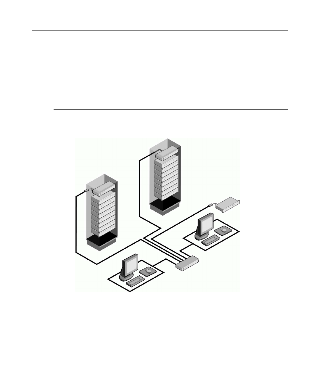
AutoView Switch
(Cascaded)
Legacy Switch
(Cascaded)
AVR IQ
or IAC
Module
Analog
Connection
Figure 1.1: Example of an AutoView Switch Configuration
Rack of Servers
Critical Server
AutoView Switch
(Main)
Analog
Connection
Page 14

4 AutoView 1400/1500/2000 Installer/User Guide
Safety Precautions
To avoid potential video and/or keyboard problems when using Avocent products:
• Ιf the building has 3-phase AC power, ensure that the computers and monitors are on the same
phase. For best results, they should be on the same circuit.
• Use only Avocent-supplied cable to connect computers and KVM switches. Avocent
warranties do not apply to damage resulting from user-supplied cable.
To avoid potentially fatal shock hazard and possible damage to equipment, please observe the
following precautions:
• Do not use a 2-wire extension cord in any Avocent product configuration.
• Test AC outlets at the computer and monitor for proper polarity
and grounding.
• Use only with grounded outlets at both the computer and monitor. When using a backup
Uninterruptible Power Supply (UPS), power the computer, the monitor and the AutoView
switch off the supply.
NOTE: The AC inlet is the main disconnect.
Rack mount safety considerations
• Elevated Ambient Temperature: If installed in a closed rack assembly, the operation
temperature of the rack environment may be greater than room ambient. Use care not to exceed
the rated maximum ambient temperature of the unit.
• Reduced Air Flow: Installation of the equipment in a rack should be such that the amount of
airflow required for safe operation of the equipment is not compromised.
• Mechanical Loading: Mounting of the equipment in the rack should be such that a hazardous
condition is not achieved due to uneven mechanical loading.
• Circuit Overloading: Consideration should be given to the connection of the equipment to the
supply circuit and the effect that overloading of circuits might have on overcurrent protection
and supply wiring. Consider equipment nameplate ratings for maximum current.
• Reliable Earthing: Reliable earthing of rack mounted equipment should be maintained. Pay
particular attention to supply connections other than direct connections to the branch circuit
(for example, use of power strips).
Page 15

CHAPTER
Installation
2
Getting Started
Before installing your AutoView switch, refer to the following list to ensure you have all items that
shipped with the AutoView switch, as well as other items necessary for proper installation.
Supplied with the AutoView switch
• Power cord
• One null modem serial cable
• Rack mounting kit
• AutoView 1400/1500/2000 Installer/User Guide
• AutoView 1400/1500/2000 Quick Installation Guide
5
Additional items needed
One IAC or AVRIQ module and CAT 5 cabling per attached server or switch
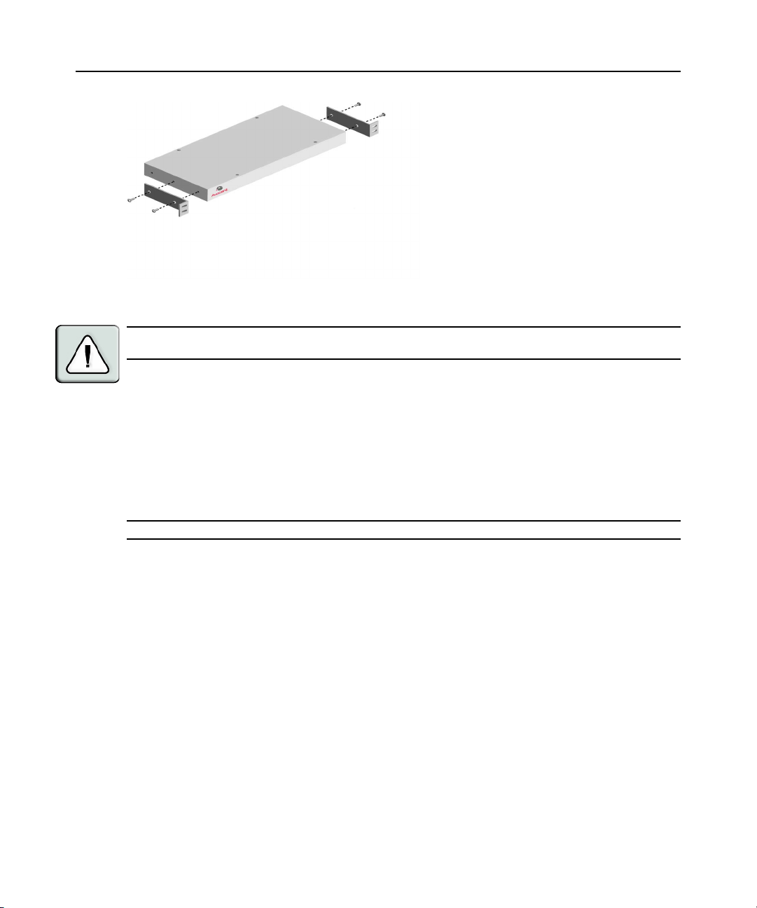
Rack Mounting Your AutoView Switch
Your AutoView switch may be rack mounted using the brackets supplied in your rack mounting kit.
Before installing the switch and other components in the rack cabinet (if not already installed),
stabilize the rack in a permanent location. Install your equipment starting at the bottom of the rack
cabinet, then work to the top.
Page 16
6 AutoView 1400/1500/2000 Installer/User Guide
Figure 2.1: AutoView Switch Horizontal Installation
CAUTION: Rack Loading - Overloading or uneven loading of racks may result in shelf or rack failure, causing
damage to equipment and possible personal injury. Do not exceed your rack load rating.
To install the 1U switch mounting bracket:
1. Remove the first two screws on each side of the switch.
2. Line up the holes in the “long side” of the kit’s side brackets with the screw holes in the switch.
3. With a Phillips screwdriver, fasten the mounting brackets to the switch using two screws on
each side.
4. Attach four cage nuts or clip nuts to the rack mounting flange of the rack cabinet so that the nut
is positioned on the inside of the rack.
NOTE: Nuts are not included with the rack mount kit.
5. Mount the switch assembly to the rack cabinet by matching the holes in the “short side” of
each bracket to an appropriate set of matching holes on your rack cabinet.
6. Next, insert the combination hex head screws through the slots in the bracket and the holes in
the mounting rail, then into the cage nuts or clip nuts.
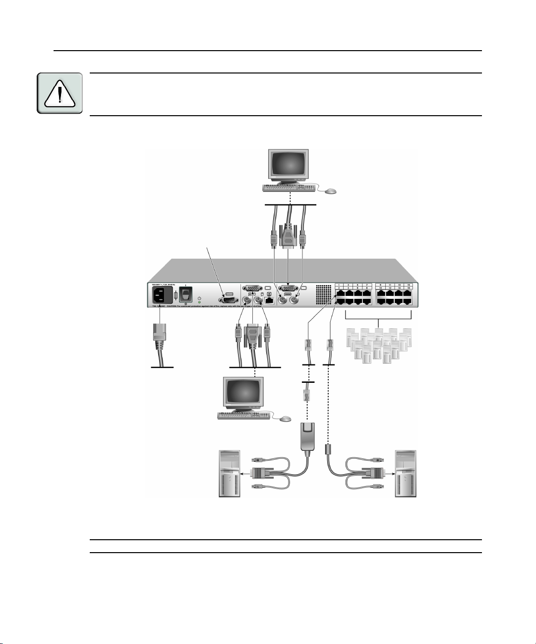
Installing the AutoView Switch
Plug the supplied power cord into the back of the appliance and then into an appropriate power
source. Figure 2.2 illustrates one possible configuration for your AutoView switch. See the following
detailed set of procedures to successfully install your appliance.
Page 17
Chapter 2: Installation 7
CAUTION: To reduce the risk of electric shock or damage to your equipment -
- Do not disable the power cord grounding plug. The grounding plug is an important safety feature.
- Plug the power cord into a grounded (earthed) outlet that is easily accessible at all times.
- Disconnect the power from the unit by unplugging the power cord from either the electrical outlet or the unit.
Analog User B
Configuration Port
(for updating firmware)
AutoView Switch
Servers 3-16
Analog User A
AVRIQ Module
Server 1
Figure 2.2: Basic AutoView Switch Configuration
NOTE: Only the AutoView 1500 and the AutoView 2000 switches support two simultaneous users.
IAC Module
Server 2
Page 18

8 AutoView 1400/1500/2000 Installer/User Guide
To connect a server using an AVRIQ module:
1. Locate the AVRIQ modules for your AutoView switch.
2. Attach the appropriately color-coded cable ends to the keyboard, monitor and mouse ports on the
first server you will be connecting to the appliance.
3. Attach one end of a CAT 5 cable to the RJ-45 connector on the AVRIQ module.
4. Connect the other end of the CAT 5 cable to the desired ARI port on the back of your
AutoView switch.
5. Repeat steps 2 through 4 for each server you wish to attach.
NOTE: When connecting a Sun AVRIQ module, you must use a multi-sync monitor to accommodate Sun
computers that support both VGA and sync-on-green or composite sync.
To connect a server using an IAC module:
1. Locate an IAC module for the server you wish to connect.
2. Attach the appropriately color-coded cable ends of the IAC module to the keyboard, monitor and
mouse ports on the server you will be connecting to the switch.
3. Attach the other end of the IAC module to an open ARI port.
4. Repeat steps 1 through 3 for each server you wish to attach.
Connecting Users
To connect local peripherals:
1. Select the keyboard, monitor and mouse to be connected to local analog user A.
2. Locate the port set labeled A on the back of the appliance. Connect these peripherals to their
respective ports.
3. Bundle and label the cables for easy identification.
4. Repeat these steps for user B, if desired.
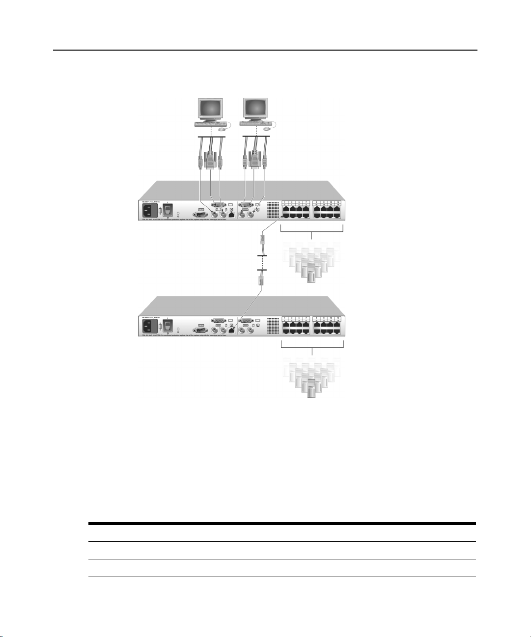
Cascading AutoView Switches
You can cascade multiple AutoView 1400/1500/2000 switches to enable one or two users to
connect to as many as 256 servers. In a cascaded system, each ARI (Avocent Rack Interface) port
on the main AutoView switch will connect to the ACI (Avocent Console Interface) port on each
cascaded AutoView switch. Each cascaded switch can then be connected to a server with an
AVRIQ module or IAC. The example shown in Figure 2.3 shows one AutoView switch cascaded
under the main switch, enabling the connection of up to 15 primary servers and 16 secondary
servers. Using this configuration, you could cascade 16 AutoView switches under the main switch,
enabling the connection of up to 256 servers. Only one level of tiering is supported in this type of
configuration, which means you cannot cascade any additional legacy switches or another
AutoView switch.
Page 19

Chapter 2: Installation 9
In this configuration, the local port OSCAR interface is disabled in switches cascaded below the
main AutoView switch.
To cascade multiple AutoView switches:
1. Connect the cascaded AutoView switch to each server as described in the previous Installing
the AutoView Switch section.
2. Connect the local peripherals to analog user A and/or B of the main switch as described in To
connect local peripherals.
3. Attach one end of the CAT 5 cabling that will run between your main and cascaded AutoView
switch to the RJ-45 ACI port on the cascaded AutoView switch.
4. Attach the other end of the CAT 5 cable to one of the RJ-45 ARI ports on the main
AutoView switch.
NOTE: The system will automatically “merge” the two switches together as one. All servers connected to the
cascaded AutoView switch will display on the main AutoView switch server list in the OSCAR interface.
5. Repeat steps 3 and 4 for all additional (secondary) cascaded AutoView switches you wish
to attach.
Page 20
10 AutoView 1400/1500/2000 Installer/User Guide
Analog User A
ACI Port
Analog User B
AutoView 2000 Switch
ARI Ports
15 Primary
Servers
AutoView 2000 Switch (cascaded)
16 Secondary
Servers
Figure 2.3: AutoView 2000 Switch Configuration with a Cascaded Switch
Adding Legacy Switches
You can add legacy switches to the AutoView switching system for easy integration into your
existing configuration. In a cascaded system, each ARI port will accommodate up to 24 servers.
See the following table for legacy switches compatible with the AutoView switching system.
Table 2.1: Legacy Switch Support
Legacy Product Model Numbers
OutLook ES switch 140ES, 180ES, 280ES, 1160ES, 2160ES, 4160ES
AutoView switch AV200-4, AV200-8, AV400-4, AV400-8, AV416, AV424, AV1400, AV1500, AV2000
Page 21
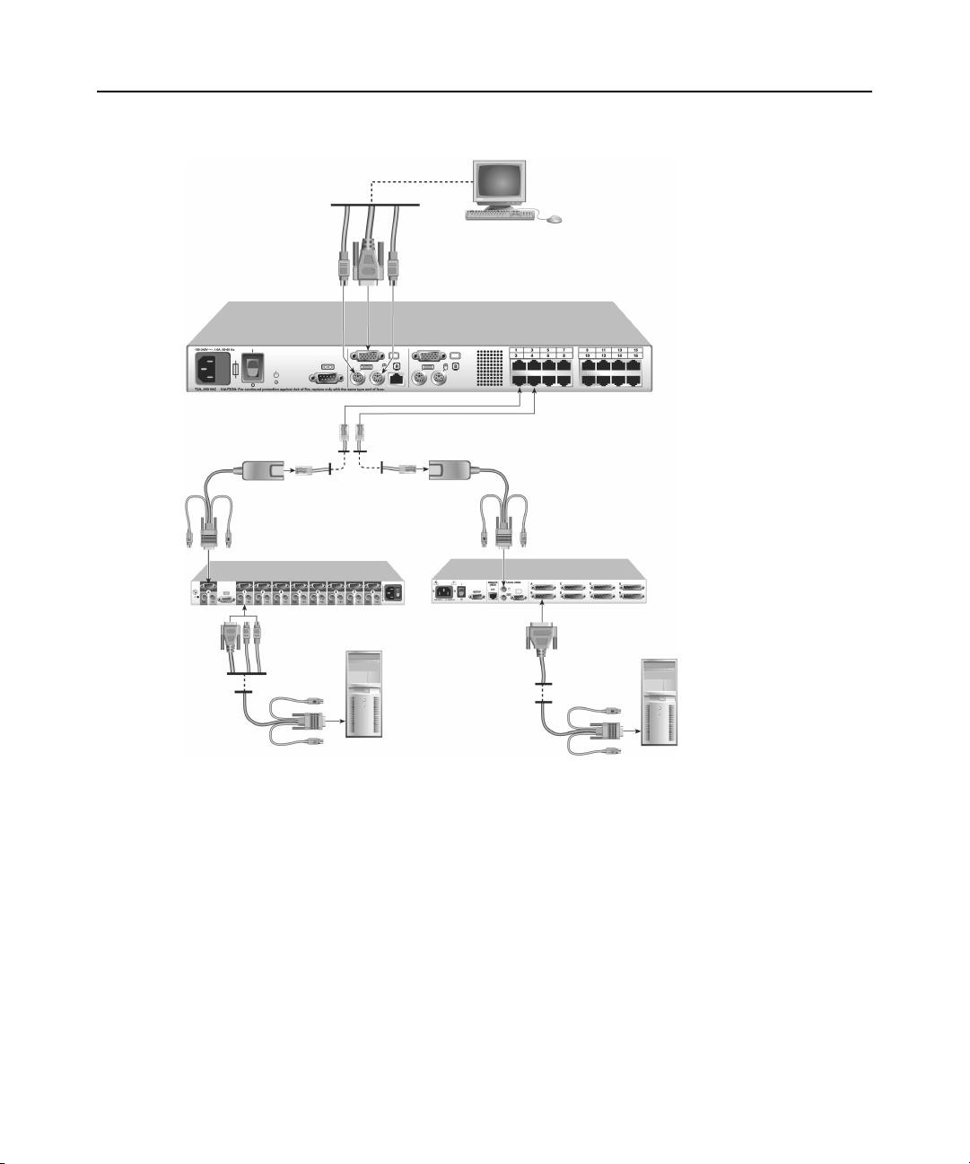
AVRIQ Module
PS/2, USB, Sun and serial
cables are available
Chapter 2: Installation 11
Local Analog User A
AutoView 2000 Switch
AVRIQ Module
OutLook ES Switch
Server 1
AutoView 200/400 Switch
Server 2
Figure 2.4: AutoView 2000 Switch Configuration with Legacy KVM Switches
Page 22
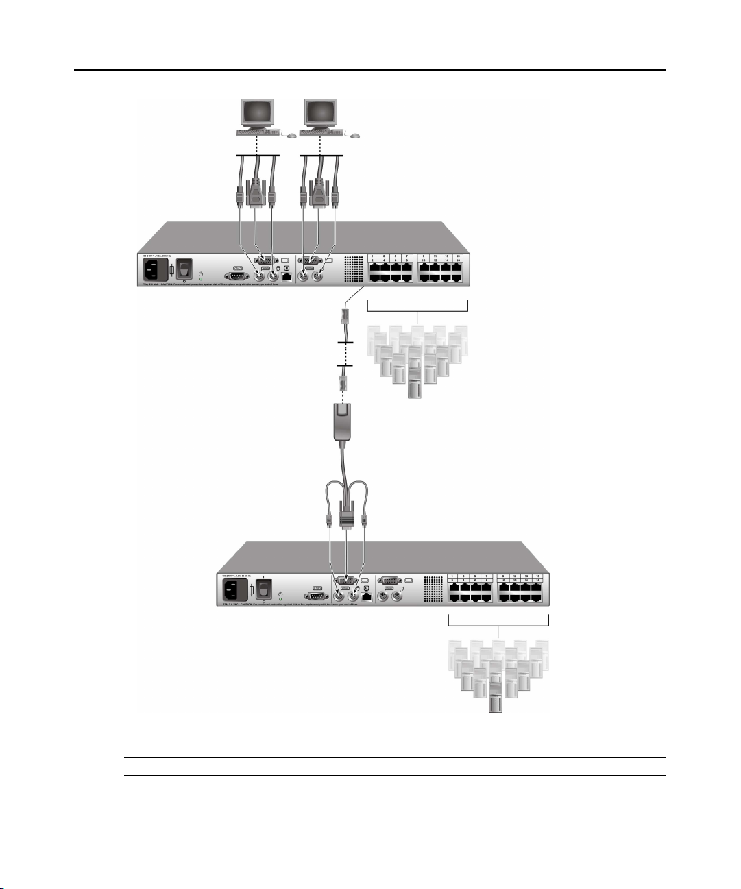
12 AutoView 1400/1500/2000 Installer/User Guide
Local Analog User A
AVRIQ Module
PS/2, USB, Sun and serial
modules are available
Local Analog User B
AutoView 1400/1500/2000 Switch
Secondary
Servers
AutoView 1400/1500/2000 Switch
Figure 2.5: AutoView Switch Configuration with AutoView 1400/1500/2000 Switches
NOTE: The PS2IAC modules can be utilized in Figure 2.5.
Secondary
Servers
Page 23

Chapter 2: Installation 13
To add a legacy KVM switch:
1. Mount the primary KVM switch into your rack cabinet.
2. Connect one end of a CAT 5 cable to an available port on the back of your AutoView switch.
3. Attach the keyboard, monitor and mouse connectors of the AVRIQ module to a user port on
your cascaded switch.
4. Attach the other end of the CAT 5 cabling to the RJ-45 connector on the AVRIQ module.
5. Connect the servers to your cascaded switch according to the instructions included with
the switch.
6. Power cycle the cascaded switch to enable its local user port to recognize the AVRIQ module.
7. Repeat steps 2 to 6 for all cascaded switches you wish to attach to your system.
To connect local peripherals:
1. Select the keyboard, monitor and mouse to be connected to local user A.
2. Locate the port set labeled A on the back of the switch. Connect these peripherals to their
respective ports.
3. For the multiuser, 16-port AutoView switch, repeat steps 1 and 2 for the local analog port set
labeled B.
- or For the AutoView 1400/1500 switch, proceed to step 4.
4. Bundle and label the cables for easy identification.
Setting Up Your AutoView Switching System
The AutoView switching system enables you to auto detect and configure each port on your
appliance. Chapter 3 provides detailed instructions on name customization and OSCAR interface
setup and configuration.
Page 24

14 AutoView 1400/1500/2000 Installer/User Guide
Page 25
CHAPTER
Basic Operations
3
Controlling Your System at the Analog Ports
The AutoView switch features one or two analog port sets on the back of the switch that allow you
to connect a monitor and a PS/2 keyboard and mouse for direct analog access. The AutoView
switch uses the OSCAR interface, featuring intuitive menus to configure your system and
select servers.
Viewing and Selecting Ports and Servers
Use the OSCAR interface Main dialog box to view, configure and control servers in the AutoView
switching system. View your servers by name, port or by the unique Electronic ID number (EID)
embedded in each AVRIQ module and IAC. You will see an OSCAR interface-generated port list
by default when you first launch the OSCAR GUI.
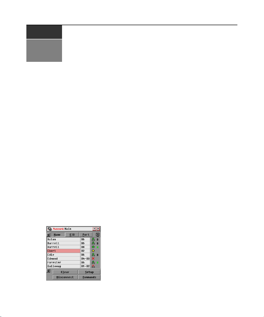
The Port column indicates the ARI port to which a server is connected. If you connect a legacy KVM
switch to the main AutoView switch or a cascaded AutoView switch, the port numbering displays
the ARI port first, then the switch port to which the server is connected. For example, in Figure 3.1,
servers 04-03 and 01-02 are connected to switches, then to servers on ports 03 and 02 respectively.
15
To access the Main dialog box:
Press
Print Screen to launch the OSCAR interface. The Main dialog box displays.
Figure 3.1: Example of Configured Main Dialog Box
Page 26

16 AutoView 1400/1500/2000 Installer/User Guide
NOTE: You can also press the Control key twice, the Alt key twice or the Shift key twice within one second to
launch the OSCAR interface. See
can use this key sequence in any place you see Print Screen throughout this installer/user guide.
Changing the display behavior
Viewing the status of your switch
The status of the servers in your system is indicated in the right columns of the Main dialog box.
The following table describes the status symbols.
Table 3.1: OSCAR Interface Status Symbols
Symbol Description
AVRIQ modules and IACs are online (green circle).
AVRIQ modules and IACs are offline or are not operating properly.
Server is cascaded through a cascade legacy switch. The switch is online and has power.
Server is cascaded through a cascade legacy switch. The switch is offline or has no power.
later in this chapter for further details. You
AVRIQ module is being upgraded (yellow circle).
AVRIQ modules and IACs are being accessed by the indicated user channel (green
channel letter).
AVRIQ modules and IACs are blocked by the indicated user channel (black channel letter).
Selecting servers
Use the Main dialog box to select servers. When you select a server, the switch reconfigures the
keyboard and mouse to the proper settings for that server.
To select servers:
Double-click the server name, EID or port number.
-or-
If the display order of your server list is by port (Port
and press
Enter.
button is depressed), type the port number
-or-
If the display order of your server list is by name or EID number (Name
or EID button is
depressed), type the first few characters of the name of the server or the EID number to establish it
as unique and press
Enter.
Page 27

Chapter 3: Basic Operations 17
To select the previous server:
Press
Print Screen and then Backspace. This key combination toggles you between the previous
and current connections.
To disconnect the user from a server:
Press
Print Screen and then Alt+0. This leaves the user in a free state, with no server selected. The
status flag on your desktop displays Free.
Soft switching
Soft switching is the ability to switch servers using a hotkey sequence. You can soft switch to a server by
pressing
Print Screen and then typing the first few characters of its name or number. If you have set a
Screen Delay Time and you press the key sequences before that time has elapsed, the OSCAR interface
will not display.
To configure servers for soft switching:
1. Press
Print Screen to launch the OSCAR interface. The Main dialog box displays.
2. Click Setup - Menu. The Menu dialog box displays.
3. For Screen Delay Time, type the number of seconds of delay desired before the Main dialog
box is displayed after
Print Screen is pressed.
4. Click OK.
To soft switch to a server:
1. To select a server, press
Print Screen. If the display order of your server list is by port (Port
button is depressed), type the port number and press
-orIf the display order of your server list is by name or EID number (Name or EID
depressed), type the first few characters of the name of the server or the EID number to
establish it as unique and press
Enter.
2. To switch back to the previous server, press
Navigating the OSCAR Interface
This table describes how to navigate the OSCAR interface using the keyboard and mouse.
Table 3.2: OSCAR Interface Navigation Basics
This Keystroke Does This
Print Screen,Ctrl-Ctrl
Shift-Shift, and/or
Alt-Alt
Activates the OSCAR interface. See
chapter for further details.
Enter.
Print Screen then Backspace.
Changing the display behavior
button is
later in this
Print Screen-Print
Screen
Press Print Screen twice to send the Print Screen keystroke to the currently
selected device.
Page 28

18 AutoView 1400/1500/2000 Installer/User Guide
Table 3.2: OSCAR Interface Navigation Basics (Continued)
This Keystroke Does This
F1
Escape
Alt+Hotkey
Alt+X Closes the current dialog box and returns to the previous one.
Alt+O
Single-click, Enter
Enter
Print Screen,
Backspace
Print Screen, Alt+0
(zero)
Print Screen, Pause
Up/Down Arrows Moves the cursor from line to line in lists.
Right/Left Arrows
Opens the Help screen for the current dialog box.
Closes the current dialog box without saving changes and returns to the previous
one. In the Main dialog box, it closes the OSCAR interface and returns to the flag. In
a message box, it closes the pop-up box and returns to the current dialog box.
Opens dialog boxes, selects or checks options and executes actions when used with
underlined or other designated letters.
Selects the
In a text box, selects the text for editing and enables the Left and Right Arrow keys
to move the cursor. Press Enter again to quit the edit mode.
Completes a switch in the Main dialog box and exits the OSCAR interface.
Toggles back to previous selection.
Immediately disengages a user from a server; no server is selected. Status flag
displays
Immediately turns on screen saver mode and prevents access to that specific
console, if it is password protected.
Moves the cursor between columns. When editing a text box, these keys move the
cursor within the column.
OK
button, then returns to the previous dialog box.
Free
. (This only applies to the 0 on the keyboard and not the keypad.)
Page Up/Page Down Pages up and down through Name and Port lists and Help pages.
Home/End Moves the cursor to the top or bottom of a list.
Delete Deletes characters in a text box.
Page Up/Page Down Pages up and down through Name and Port lists and Help pages.
Numbers Type from the keyboard or keypad.
Print Screen, Ctrl+ F4
Logs the current user out of the switch (only available when Enable Local User
Accounts is checked on the Security screen).
Page 29

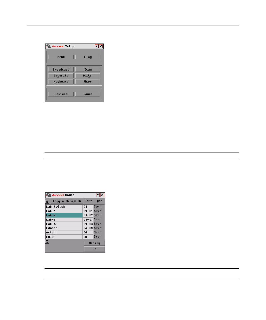
Configuring OSCAR Interface Menus
You can configure your AutoView switch from the Setup menu within the OSCAR interface. Select
the
Names
button when initially setting up your switch to identify servers by unique names. Select the
other setup features to manage routine tasks for your servers from the OSCAR interface menu.
Table 3.3: Setup Features to Manage Routine Tasks for Your Servers
Feature Purpose
Change the server listing between numerically by port or EID number and
Menu
Flag Change display, timing, color or location of the status flag.
alphabetically by name. Change the Screen Delay Time before the OSCAR interface
displays after pressing Print Screen.
Chapter 3: Basic Operations 19
Broadcast
Scan Set up a custom scan pattern for up to 16 servers.
Security Set passwords to restrict server access. Enable the screen saver.
Devices Identify the appropriate number of ports on an attached cascaded switch.
Names Identify servers by unique names.
Switch Choose the Switch Mode and the Share Mode time-out.
Keyboard Choose the keyboard country code that is sent to the AVRIQ module and IAC.
User
NOTE: Only the Menu, Flag and Security screens are available to the users without administrator privileges. All
other screens, except the User screen, are available to the administrator when Enable Local User Accounts is
disabled in the Security screen.
Set up to simultaneously control multiple servers through keyboard and
mouse actions.
Allows the administrator to set up the Local User Accounts (only visible when Enable
Local User Accounts is checked on the Security screen).
To access the Setup menu:
1. Press
Print Screen to launch the OSCAR interface. The Main dialog box displays.
2. Click Setup. The Setup dialog box displays.
Page 30
20 AutoView 1400/1500/2000 Installer/User Guide
Figure 3.2: Setup Dialog Box
Assigning server names
Use the Names dialog box to identify individual servers by name rather than by port number. The
Names list is always sorted by port order. Names are stored in the AVRIQ or IAC module, so even
if you move the module/cable to another ARI port, the name and configuration will be recognized
by the switch.
NOTE: If a server is turned off, its respective AVRIQ or IAC module will not appear in the Names list.
To access the Names dialog box:
1. Press
2. Click Setup
Figure 3.3: Names Dialog Box
NOTE: If the server list changes, the mouse cursor will turn into an hourglass as the list is automatically updated. No
mouse or keyboard input will be accepted until the list update is complete.
Print Screen to launch the OSCAR interface. The Main dialog box will appear.
- Names. The Names dialog box displays.
Page 31

Chapter 3: Basic Operations 21
To assign names to servers:
1. In the Names dialog box, select a server name or port number and click Modify. The Name
Modify dialog box displays.
Figure 3.4: Name Modify Dialog Box
2. Type a name in the New Name box. Names of servers may be up to 15 characters long. Supported
characters include: A to Z, a to z, 0 to 9, space and hyphen.
3. Click OK to transfer the new name to the Names dialog box. Your selection is not saved until
you click OK in the Names dialog box.
4. Repeat steps 1 to 3 for each server in the system.
5. Click OK in the Names dialog box to save your changes.
-orClick X or press
Escape to exit the dialog box without saving changes.
NOTE: If an AVRIQ module has not been assigned a name, the EID is used as the default name.
Assigning device types
The AutoView switch automatically discovers cascaded KVM switches, but you will need to specify
the number of ports on the cascaded switch through the Devices dialog box. You will see an Sw-8 or
Sw-24 display in the Type category for the cascaded switch. Select the switch from the list and the
Modify button displays, allowing you to assign it the appropriate number of ports.
NOTE: The Modify button will only be available if a configurable switch is selected.
To access the Devices dialog box:
1. Press
2. Click Setup - Devices. The Devices dialog box displays.
Print Screen to launch the OSCAR interface. The Main dialog box will appear.
Page 32

22 AutoView 1400/1500/2000 Installer/User Guide
Figure 3.5: Devices Dialog Box
When the AutoView switch discovers a cascaded switch, you will notice the port numbering
change to accommodate each server under that switch. For example, if the switch is connected to
ARI port 6, the switch port would be listed as 06 and each server under it would be numbered
sequentially 06-01, 06-02 and so on.
To assign a device type:
1. In the Devices dialog box, select the desired port number.
2. Click Modify. The Device Modify dialog box displays.
Figure 3.6: Device Modify Dialog Box
3. Choose the number of ports supported by your cascaded switch and click OK.
4. Repeat steps 1 to 3 for each port requiring a device type to be assigned.
5. Click OK in the Devices dialog box to save settings.
NOTE: Changes made in the Device Modify dialog box are not saved until you click
dialog box.
OK
in the Devices
Page 33

Changing the display behavior
Use the Menu dialog box to change the display order of servers, change the key sequence to launch
the OSCAR interface and set a Screen Delay Time for the OSCAR interface. The display order setting
alters how servers display in several screens including the Main, Devices and Broadcast dialog boxes.
To access the Menu dialog box:
Chapter 3: Basic Operations 23
1. Press
Print Screen to launch the OSCAR interface. The Main dialog box displays.
2. Click Setup - Menu in the Main dialog box. The Menu dialog box displays.
Figure 3.7: Menu Dialog Box
To choose the default display order of servers:
1. Select Name to display servers alphabetically by name.
-orSelect EID to display servers numerically by EID number.
-orSelect Port to display servers numerically by port number.
2. Click OK.
To set up key sequences to launch the OSCAR interface:
1. Click the box next to the key sequence you want to start the OSCAR interface. Unchecking all
boxes will leave
Print Screen as the default.
2. Click OK.
To set a Screen Delay Time for the OSCAR interface:
1. Type in the number of seconds (0 to 9) to delay the OSCAR interface display after you press
Screen
. Entering 0 will instantly launch the OSCAR interface with no delay.
Print
2. Click OK.
Page 34

24 AutoView 1400/1500/2000 Installer/User Guide
Setting a Screen Delay Time allows you to complete a soft switch without the OSCAR interface
displaying. To perform a soft switch, see Soft switching in this chapter.
Setting the keyboard country code
The AutoView 1400/1500/2000 switch can be configured to recognize a variety of keyboards. The
default setting is for a US keyboard. If you wish to change this configuration, the Keyboard dialog
box allows you to select a different keyboard country code.
NOTE: Ensure that the country code selected on your Sun server matches the Keyboard Country Code selected
in the OSCAR or your keyboard will not be mapped correctly.
Figure 3.8: Keyboard Box
To change the keyboard country code:
1. Press
Print Screen to launch the OSCAR interface. The Main dialog box will appear.
2. Click Setup-Keyboard. The Keyboard dialog box displays.
3. Select your desired keyboard country code and click OK.
4. A Keyboard Warning dialog box will appear to confirm your changes.
Page 35

5. Click OK for changes to take effect.
Figure 3.9: Keyboard Warning Dialog Box
Controlling the status flag
The status flag displays on your desktop and shows the name or EID number of the selected server
or the status of the selected port. Use the Flag dialog box to configure the flag to display by server
name or EID number, or to change the flag color, opacity, display time and location on the desktop.
Table 3.4: OSCAR Interface Status Flags
Flag Description
Chapter 3: Basic Operations 25
Flag type by name
Flag type by EID number
Flag indicating that the user has been disconnected from all systems
Flag indicating that Broadcast Mode is enabled
To access the Flag dialog box:
1. Press
Print Screen. The Main dialog box will appear.
2. Click Setup - Flag. The Flag dialog box displays.
Page 36

26 AutoView 1400/1500/2000 Installer/User Guide
Figure 3.10: Flag Dialog Box
To determine how the status flag is displayed:
1. Select Name or EID to determine what information will be displayed.
2. Select Displayed to show the flag all the time or select Timed to display the flag for only five
seconds after switching.
3. Select a flag color in Display Color.
4. In Display Mode, select Opaque for a solid color flag or select Transparent to see the desktop
through the flag.
5. To position the status flag on the desktop:
a. Click Set Position to gain access to the Set Position Flag screen.
b. Left-click on the title bar and drag to the desired location.
c. Right-click to return to the Flag dialog box.
Figure 3.11: Set Position Flag
NOTE: Changes made to the flag position are not saved until you click OK in the Flag dialog box.
6. Click OK to save settings.
-orClick X to exit without saving changes.
Setting console security
The OSCAR interface enables you to set security on your analog port console. You can establish a
screen saver mode that engages after your console remains unused for a specified Inactivity Time.
Page 37

Chapter 3: Basic Operations 27
Once engaged, your console will remain locked until you press any key or move the mouse. You
will then need to type in your password to continue.
Use the Security dialog box to lock your console with password protection, set or change your
password and enable the screen saver.
NOTE: If a password has been previously set, you will have to enter the password before you can access the
Security dialog box. If you should lose or forget your password, please contact Avocent Technical Support about
returning your switch for service. See
Appendix D:Technical Support
for contact information.
To access the Security dialog box:
1. Press
Print Screen to launch the OSCAR interface. The Main dialog box will appear.
2. Click Setup - Security. The Security dialog box displays.
Figure 3.12: Security Dialog Box
NOTE: Figure 3.12 is the Security screen for the administrator and local user when the Enable User Accounts
feature is turned off. The restricted user can only access the Change Password function of this screen.
To set or change the password:
1. Single-click and press
2. Type the new password in the New text box and press
Enter or double-click in the New text box.
Enter.
Passwords must contain both alpha and numeric characters, are case sensitive and may be up to
12 characters long. Supported characters are: A to Z, a to z, 0 to 9, space and hyphen.
3. In the Repeat box, type the password again and press
Enter.
4. Click OK to change only your password, and then close the dialog box.
To password protect your console:
1. Set your password as described in the previous procedure.
2. Select Enable Screen Saver.
Page 38

28 AutoView 1400/1500/2000 Installer/User Guide
3. Type the number of minutes for Inactivity Time (from 1 to 99) to delay activation of password
protection and the screen saver feature.
4. For Mode, select
CAUTION: Monitor damage can result from the use of Energy mode with monitors not compliant with
ENERGY STAR.
Energy
if your monitor is E
5. (Optional) Click Test to activate the screen saver test which lasts 10 seconds then returns you to
the Security dialog box.
6. Click OK.
To log in to your console:
1. Press any key or move the mouse.
2. The Password dialog box displays. Type your password, then click OK.
3. The Main dialog box displays if the password was entered properly.
To remove password protection from your console:
1. From the Main dialog box, click Setup - Security; the Password dialog box displays. Type your
password, then click OK.
2. In the Security dialog box, single-click and press
the box blank. Press
3. Single-click and press
Press
Enter.
Enter.
Enter or double-click in the Repeat box. Leave the box blank.
4. Click OK to eliminate your password.
NERGY STAR
®
compliant; otherwise select
Enter or double-click in the New box. Leave
Screen
.
To enable local user accounts:
1. Click the Enable Local User Accounts checkbox.
2. Click OK. See Chapter 4 for more information on setting up local user accounts.
To disable local user accounts (admin user only):
1. Click Enable Local User Accounts to uncheck the box and disable this option.
2. Click OK.
To enable the screen saver mode with no password protection:
1. If your console does not require a password to gain access to the Security dialog box, proceed
to step 2.
-orIf your console is password protected, see the previous procedure, then go to step 2.
2. Select Enable Screen Saver.
3. Type the number of minutes for Inactivity Time (from 1 to 99) to delay activation of the
screen saver.
Page 39

Chapter 3: Basic Operations 29
4. Choose Energy if your monitor is ENERGY STAR compliant; otherwise select Screen.
CAUTION: Monitor damage can result from the use of Energy mode with monitors not compliant with
ENERGY STAR.
5. (Optional) Click Test to activate the screen saver test which lasts 10 seconds then returns you
to the Security dialog box.
6. Click OK.
NOTE: Activation of the screen saver mode disconnects the user from a server; no server is selected. The status
flag displays
Free
.
To exit the screen saver mode:
Press any key or move your mouse. The Main dialog box displays and any previous server
connection will be restored.
Page 40

30 AutoView 1400/1500/2000 Installer/User Guide
To turn off the screen saver:
1. In the Security dialog box, clear Enable Screen Saver.
2. Click OK.
To immediately turn on the screen saver:
Press
Print Screen, then press Pause.
Displaying Version Information
The OSCAR interface enables you to display the versions of the AutoView switch, as well as the
AVRIQ module and IAC module firmware. For optimum performance, keep your firmware
current. For more information, see Appendix A.
To display version information:
1. Press
2. Click Commands
Print Screen. The Main dialog box will appear.
- Display Versions. The Version dialog box displays. The top half of the box
lists the subsystem versions in the appliance.
Figure 3.13: Version Dialog Box
3. Click the Target button to view individual AVRIQ and IAC module version information. The
Target Selection dialog box displays.
Page 41

Chapter 3: Basic Operations 31
Figure 3.14: Target Selection Dialog Box
4. Select an AVRIQ or IAC module to view and click the Version button. The Target Version
dialog box displays. For more information on loading firmware, see Appendix A.
Figure 3.15: Target Version Dialog Box
5. Click X to close the Target Version dialog box.
NOTE: The Load Firmware button will only display for an AVRIQ module; IAC modules are not upgradable.
Only the administrator and the user (when local user accounts are disabled) can upgrade the firmware on an
AVRIQ module.
Scanning Your System
In Scan Mode, the appliance automatically scans from port to port (server to server). You can scan
up to 16 servers, specifying which servers to scan and the number of seconds that each server will
display. The scanning order is determined by placement of the server in the list. The list is always
shown in scanning order. You can, however, choose to display the server’s name or EID number by
pressing the appropriate button.
Page 42

32 AutoView 1400/1500/2000 Installer/User Guide
To add servers to the scan list:
1. If the OSCAR interface is not open, press
Print Screen. The Main dialog box will appear.
2. Click Setup - Scan. The Scan dialog box displays.
Figure 3.16: Scan Dialog Box
3. The dialog box contains a listing of all servers attached to your appliance. Click the checkbox
next to the servers you wish to scan.
-orDouble-click on a server’s name or port.
-orPress
Alt and the number of the server you wish to scan. You can select up to 16 servers from the
entire list.
4. In the Scan Time box, type the number of seconds (from 3 to 99) of desired time before the
scan moves to the next server in the sequence.
5. Click OK.
To remove a server from the scan list:
1. In the Scan dialog box, deselect the checkbox next to the server to be removed.
-orDouble-click on the server’s name or port.
-orClick the Clear button to remove all servers from the scan list.
2. Click OK.
To start the Scan Mode:
1. If the OSCAR interface is not open, press
Print Screen. The Main dialog box will appear.
2. Click Commands. The Commands dialog box displays.
Page 43

Chapter 3: Basic Operations 33
Figure 3.17: Commands Dialog Box
NOTE: Figure 3.17 shows the Commands screen for the administrator and local user when the Enable User
Accounts feature is turned off. The restricted user will only have access to the Display Versions, Device Reset
and Log Out buttons.
3. Select Scan Enable in the Commands dialog box.
4. Click X to close the Commands dialog box.
NOTE: Scanning will begin when the Main dialog box or flag is displayed. Scanning is inhibited in any other
OSCAR interface dialog box.
To cancel Scan Mode:
1. Select a server if the OSCAR interface is open.
-orMove the mouse or press any key on the keyboard if the OSCAR interface is not open.
Scanning will stop at the currently selected server.
2. Press
Print Screen. The Main dialog box will appear.
3. Click Commands. The Commands dialog box displays.
4. Clear Scan Enable.
Running System Diagnostics
You can validate the integrity of your system through the Run Diagnostics command. This command
checks the main board functional sub-systems (memory, communications, switch control and the
video channels) for each system controller. When you select the Run Diagnostics option, you will
receive a warning indicating that all users (remote and local) will be disconnected. Click OK to
confirm and begin the test.
The Diagnostics dialog box displays. The top section of the dialog box displays the hardware tests.
The bottom portion divides the tested AVRIQ and IAC modules into three categories: On-line,
Offline or Suspect.
Page 44

34 AutoView 1400/1500/2000 Installer/User Guide
NOTE: AVRIQ or IAC modules may appear to be offline while being upgraded.
Figure 3.18: Diagnostics Dialog Box
Next to each item to be tested, you will see a pass (green circle) or fail (red x) symbol display to
the left of each item as that test finishes. The following table details each of the tests.
Table 3.5: Diagnostic Test Details
Test Description
Memory Tests Reports on the condition of the main board RAM
Firmware CRCs
Comm Interfaces Validates the current firmware images stored in the system’s Flash
Switch Controller test Verifies the switch matrix controller is accessible and functional
Local Video
On-line Targets
Offline Targets
Suspect Targets
Reports on the condition of the main board RAM
Indicates the condition of the local video monitor
Indicates the total number of currently connected and powered targets
Indicates the number of targets that have been connected successfully in the
past and are powered down
Indicates the number of targets that have been detected, but are either
unavailable for connection or have dropped packets during the ping tests
To run diagnostic tests:
1. If the OSCAR interface is not open, press
2. Click Commands
- Run Diagnostics. A warning message displays indicating that all users will
Print Screen. The Main dialog box will appear.
be disconnected.
Page 45

Figure 3.19: Diagnostics Warning Dialog Box
3. Click OK to begin diagnostics.
-orClick X or press
Escape to exit the dialog box without running a diagnostic test.
4. All users are disconnected and the Diagnostics dialog box displays.
5. As each test is finished, a pass (green circle) or fail (red x) symbol displays. The test is complete when the last test’s symbol displays.
Broadcasting to Servers
Chapter 3: Basic Operations 35
The analog user can simultaneously control more than one server in a system to ensure that all
selected servers receive identical input. You can choose to broadcast keystrokes and/or mouse
movements independently.
NOTE: You can broadcast to up to 16 servers at a time, one server per ARI port.
To access the Broadcast dialog box:
1. Press
2. Click Setup
Print Screen. The Main dialog box will appear.
- Broadcast. The Broadcast dialog box displays.
Page 46

36 AutoView 1400/1500/2000 Installer/User Guide
Figure 3.20: Broadcast Dialog Box
NOTE: Broadcasting Keystrokes - The keyboard state must be identical for all servers receiving a broadcast to
interpret keystrokes identically. Specifically, the Caps Lock and Num Lock modes must be the same on all
keyboards. While the appliance attempts to send keystrokes to the selected servers simultaneously, some servers
may inhibit and thereby delay the transmission.
NOTE: Broadcasting Mouse Movements - For the mouse to work accurately, all systems must have identical
mouse drivers, desktops (such as identically placed icons) and video resolutions. In addition, the mouse must be
in exactly the same place on all screens. Because these conditions are extremely difficult to achieve,
broadcasting mouse movements to multiple systems may have unpredictable results.
To broadcast to selected servers:
1. From the Broadcast dialog box, select the mouse and/or keyboard checkboxes for the servers
that are to receive the broadcast commands.
-orPress the
select the keyboard checkbox and/or
Up or Down Arrow keys to move the cursor to the target server. Then press Alt+K to
Alt+M to select the mouse checkbox. Repeat for
additional servers.
2. Click OK to save the settings and return to the Setup dialog box. Click X or press
Escape to
return to the Main dialog box.
3. Click Commands. The Commands dialog box displays.
4. Click the Broadcast Enable checkbox to activate broadcasting. The Broadcast Enable
Confirm/Deny dialog box displays.
Page 47

Chapter 3: Basic Operations 37
Figure 3.21: Broadcast Enable Confirm/Deny Dialog Box
5. Click OK to enable the broadcast. Click X or press Escape to cancel and return to the Commands dialog box.
6. If broadcasting is enabled, type the information and/or perform the mouse movements you
want to broadcast from the switch. Only servers in the list are accessible.
NOTE: The other user is disabled when Broadcast Mode is enabled.
To turn broadcasting off:
From the Commands dialog box, clear the Broadcast Enable checkbox.
Changing Your Switch Mode
Your AutoView switch allows you to connect to attached servers using two methods: Preemptive
and Cooperative.
Select Preemptive (default setting) to allow any user to select any server at any time; a request from
another user disconnects the current user without warning.
-or-
Select Cooperative to maintain the current user connection; the current user will not be
disconnected if another user requests connection.
To access the Switch dialog box:
1. Press
2. Click Setup - Switch. The Switch dialog box displays.
Print Screen. The Main dialog box will display.
Page 48

38 AutoView 1400/1500/2000 Installer/User Guide
Figure 3.22: Switch Dialog Box
3. Select either Preemptive or Cooperative as your Switch Mode.
4. Click OK to save changes. Click X or press
Setting the Share Mode feature
The Share Mode feature of the AutoView 1400/1500/2000 switches allows two users to gain
access to a primary server.
To enable Share Mode:
Escape to cancel.
1. Press
Print Screen. The Main dialog box will display.
2. Click Setup - Switch. The Switch dialog box displays.
3. Select Share Enable from the Switch dialog box.
4. Choose the amount of inactivity time for the target (up to 600 seconds) before another user can
take control of the target.
5. Click OK to save changes. Click X or press
Escape to cancel.
Page 49

CHAPTER
Advanced Operations
4
Using Administrator Privileges
The AutoView 1400/1500/2000 switches allow up to four users and one administrator to log into a
switch, with the administrator having the ability to restrict users from accessing the targets via the
Security menu. The administrator can edit, access and/or delete user accounts.
39
Figure 4.1: Security Menu
To access the User Setup screen (administrator only):
1. Click the Enable User Account checkbox in the Security menu. The Setup menu will appear.
2. Click the OK button.
3. Click the User button on the Setup screen to enter the User Setup screen.
NOTE: Clicking the
users will remain logged out until your changes are complete.
User
button on the Setup screen will automatically log out any currently logged in user. Other
Page 50

40 AutoView 1400/1500/2000 Installer/User Guide
Figure 4.2: Setup Menu (Administrator Only)
Figure 4.3: User Setup Menu (Administrator Only)
User Setup menu functions (administrator only)
The User Setup menu allows the administrator to edit, access and/or delete a user account. The
menu is only accessible if the Enable User Account checkbox is enabled in the Security menu. The
AutoView 1400/1500/2000 switches will have four standard user accounts, with the default names
of User1, User2, User3 and User4.
To edit a user:
1. Click the username of the user to be modified.
2. Click Edit to change the username and/or password of the selected user.
Page 51

Chapter 4: Advanced Operations 41
3. Click Access to restrict port access for the selected user.
4. Click Delete to restore the selected user to the default state (default name, no password, no
port access).
5. Click OK on the User Setup screen to save changes, or click the Exit button to escape without
saving any changes.
User Edit menu (administrator only)
The Edit menu allows the administrator to set or change user names and passwords for all users.
Figure 4.4: User Edit Menu (Administrator Only)
The Username field displays default names that can be edited by the administrator. Usernames
must be between 1 to 15 characters. Administrators can also set user passwords in the User Edit
menu. Passwords must be between 5 to 12 characters and must contain at least one number and one
alpha character. Administrators must verify new passwords by retyping the password in the Repeat
Password field.
NOTE: Changes are not saved until the administrator clicks OK in the User Setup menu.
User Access menu (administrator only)
The Access menu displays each user name, port number and whether the user has access to the
listed KVM ports. The administrator controls which ports are accessible to which user by clicking
in the appropriate checkbox.
Page 52

42 AutoView 1400/1500/2000 Installer/User Guide
Figure 4.5: User Access Menu (Administrator Only)
The Clear All button allows the administrator to clear access to all ports for a given user instead of
deleting the account. The Check All button allows the administrator to assign all available KVM
ports to any user.
NOTE: Changes are not saved to memory until the administrator clicks OK on the User Setup screen.
User Setup menu - Delete (administrator only)
The Delete button in the User Access menu allows an administrator to delete user accounts. Simply
select an account from the menu and click the Delete button. The deleted user account will
immediately return to default settings.
Page 53

APPENDICES
Appendices
Appendix A: Flash Upgrades
Upgrading the AutoView switch
You can upgrade the firmware of your AutoView switch by using a special update utility provided
by Avocent. This utility automatically configures the port communications settings to allow direct
downloading from the connected server.
Items needed for the upgrade
®
• Server running Windows NT
• Available serial port (COM port) on the server
• Null modem serial cable (DB-male) that connects the switch and the server
• Firmware update
To upgrade firmware:
1. Connect the standard serial cable to a COM port on the server and to the serial connector on the
back panel of the switch. Make a note of which COM port you have chosen, then turn on
the switch.
2. Go to http://www.avocent.com/support and click on All Product Upgrades to access the
firmware upgrade file. Once the download is complete, navigate to the drive where you have
saved the firmware update and unzip the file.
3. Double-click to run the file ApplianceUpdate.exe.
4. Click the Next button to display the main dialog box.
5. In the dialog box that displays, select the desired language from the selected Language
drop-down list and the appropriate COM Port from the COM Port menu.
6. Click Update.
7. Once the firmware is updated, an Update Complete message displays. Click the Close button
to exit the dialog box.
8. The switch automatically reboots after the upgrade is completed.
, Windows® 95, Windows 98 or Windows 2000
43
Possible error conditions
If the download does not execute properly, verify the following:
• Verify that the COM port is correct.
• Verify that no other program is currently using the COM port, or that no previous DOS window/shell is open that had used the desired COM port.
• Verify that no other copies of the ApplianceUpdate.exe utility are currently running.
Page 54

44 AutoView 1400/1500/2000 Installer/User Guide
• Verify that a null modem serial cable is used.
• In the selected COM port Advanced Port settings, verify that the FIFO buffers are selected and
that the receive buffer is set to High.
CAUTION: While upgrading, do not use your computer for anything else or switch between windows. Close all
other windows if necessary. If the upgrade was unsuccessful (such as during a power outage), repeat
the procedure.
Upgrading the AVRIQ module firmware
The AVRIQ modules can be upgraded individually or simultaneously.
NOTE: IAC modules are not upgradable.
To simultaneously upgrade multiple AVRIQ modules:
1. Press
Print Screen. The Main dialog box will appear.
2. Click Commands - AVRIQ Status. The AVRIQ Status dialog box displays.
Figure A.1: AVRIQ Status Dialog Box
3. Click one or more types of modules to upgrade. Click Upgrade.
4. The AVRIQ Upgrade dialog box displays. Click OK to initiate the upgrade and return to the
AVRIQ Status dialog box.
Page 55

Figure A.2: AVRIQ Upgrade Dialog Box
To upgrade AVRIQ module firmware individually:
Appendices 45
1. Press
Print Screen. The Main dialog box will appear.
2. Click Commands - Display Versions. The Version dialog box displays.
Figure A.3: Version Dialog Box
3. Click Target to view individual AVRIQ module information. The Target Selection dialog
box displays.
Page 56

46 AutoView 1400/1500/2000 Installer/User Guide
Figure A.4: Target Selection Dialog Box
4. Select an AVRIQ module to upgrade and click the Version button. The Target Version dialog
box displays.
Figure A.5: Target Version Dialog Box
5. Click the Load Firmware button. The AVRIQ Load dialog box displays.
NOTE: The
Load Firmware
button displays for AVRIQ modules only; IAC modules are not upgradable.
Page 57

Appendices 47
Figure A.6: AVRIQ Load Dialog Box
6. Click OK to initiate the upgrade and return to the Status dialog box.
NOTE: During an upgrade, the AVRIQ status indicator in the Main dialog box will be yellow. The AVRIQ module
is unavailable while an upgrade is in progress. When an upgrade is initiated, any current connection to the server
via the AVRIQ module will be terminated.
Page 58

48 AutoView 1400/1500/2000 Installer/User Guide
Appendix B: Technical Specifications
Table B.1: Product Specifications
AutoView Switch Product Specifications
ARI ports
Number 8 (AutoView 1400/1500 switch), 16 (AutoView 2000 switch)
Types PS/2, Sun, USB and serial AVRIQ modules or PS/2 and USB IACs
Connectors RJ-45
Sync Types Separate horizontal and vertical
Plug and Play DDC2B
Video Resolution Analog Port Maximum 1600 x 1280 @ 75 Hz
Update Port
Number 1
Type Serial RS-232
Connector DB9 Male
Analog Port Sets
Number 1 (AutoView 1400 switch), 2 (AutoView 1500/2000 switch)
Type PS/2, VGA and ACI
Connectors PS/2 miniDIN, 15 pin D, RJ-45
Dimensions
Dimensions
(H x W x D)
Weight 3.6 kg (8 lb) without cables
Heat Dissipation 92 BTU/Hr
Airflow 8 cfm
Power Consumption 12.5 W
AC-input power 40 W maximum
4.45 x 43.18 x 27.94 cm 1U form factor (1.75 x 17.00 x 11.00 in.)
Page 59

Table B.1: Product Specifications (Continued)
AutoView Switch Product Specifications
Appendices 49
AC-input
100 to 240 VAC Autosensing
voltage rating
AC-input current
0.5 A
rating
AC-input cable
18 AWG three-wire cable, with a three-lead IEC-320 receptacle on the power supply
end and a country or region dependent plug on the power resource end
AC-frequency 50/60 HZ
o
10
Temperature
Humidity
to 50o Celsius (50o to 122o Farenheit) operating
o
to 60o Celsius (-4o to 140o Farenheit) nonoperating
-20
20 to 80% noncondensing operating
5 to 95% noncondensing nonoperating
Safety and EMC Approvals and Markings
UL, FCC Class A, cUL, ICES Class A, CE, N, GS, IRAM, GOST, VCCI Class A,
MIC Class A, C-Tick
Page 60

50 AutoView 1400/1500/2000 Installer/User Guide
Appendix C: Sun Advanced Key Emulation
Certain keys on a standard Type 5 (US) Sun keyboard can be emulated by key press sequences on a
PS/2 keyboard. To enable Sun Advanced Key Emulation mode and use these keys, press and hold
Ctrl+Shift+Alt and then press the Scroll Lock key. The Scroll Lock LED blinks. Use the indicated
keys in Table C.1 as you would use the advanced keys on a Sun keyboard.
Table C.1: Sun Key Emulation
Sun Key (US) PS/2 Key to Enable Sun Key Emulation
Compose
Compose keypad
Power F11
Open F7
Help Num Lock
Props F3
Front F5
Application
(1)
Stop F1
Again F2
Undo F4
Cut F10
Copy F6
Paste F8
Find F9
Mute keypad /
Vol.+ keypad +
Vol.- keypad -
Command (left)
Command (left)
Command (right)
(1)Windows 95 104-key keyboard.
(2)The Command key is the Sun Meta (diamond) key.
(2)
(2)
(2)
F12
Win (GUI) left
Win (GUI) right
(1)
(1)
Page 61

Appendices 51
For example: For Stop + A, press and hold Ctrl+Shift+Alt and press Scroll Lock, then F1 + A.
These key combinations will work with the AVRIQ-USB module (if your Sun system comes with a
USB port) as well as the Sun AVRIQ-VSN and AVRIQ-WSN modules. With the exception of
these key combinations are not recognized by Microsoft Windows. Using
F12 performs a Windows
key press.
When finished, press and hold
Ctrl+Shift+Alt and then press the Scroll Lock key to toggle Sun
Advanced Key Emulation mode off.
Special considerations for Japanese Sun USB and Korean Sun USB
keyboards (AVRIQ-USB modules only)
Japanese Sun USB and Korean Sun USB keyboards assign usage IDs for certain keys that differ
from standard USB usage IDs. If AVRIQ-USB modules are attached to your Sun servers, the Han/
Zen and Katakana/Hiragana keys on Japanese Sun USB keyboards and Hangul and Hanja keys on
Korean Sun USB keyboards must be accessed using alternate keystrokes.
Due to these keyboard-specific differences, keyboard mapping inconsistencies may be encountered
when switching between target devices using Sun AVRIQ-VSN and AVRIQ-WSN modules and
target devices using AVRIQ-USB modules. These keys function normally if your Sun servers are
attached to the AutoView 1400/1500/2000 switch using an AVRIQ-VSN or AVRIQ-WSN module.
Table C.2 lists the keyboard mapping that will take place when an AVRIQ-USB module is used in
this setting.
F12,
Table C.2: PS/2-to-USB Keyboard Mappings
PS/2 Keyboard USB Usage ID Sun USB Keyboard
Right-Alt 0xE6 AltGraph Hangul Katakana/Hiragana
Windows Application 0x65 Compose Hanja Compose
Hangul 0x90 N/A N/A N/A
Hanja 0x91 N/A N/A N/A
Katakana/Hiragana 0x88 N/A N/A Han/Zen
Han/Zen 0x35 ` ~ ` ~ N/A
Korean Sun
USB Keyboard
Japanese
USB Keyboard
Page 62

52 AutoView 1400/1500/2000 Installer/User Guide
Appendix D: Technical Support
Our Technical Support staff is ready to assist you with any installation or operating issues you
encounter with your Avocent product. If an issue should develop, follow the steps below for the
fastest possible service.
To resolve an issue:
1. Check the pertinent section of this manual to see if the issue can be resolved by following the
procedures outlined.
2. Check our web site at www.avocent.com/support to search the knowledge base or use the online service request.
3. Call the Avocent Technical Support location nearest you.
Page 63

INDEX
Index
53
A
adding legacy switches 10
ARI port 15
AutoView 2000 switch
adding legacy switches
cascading 8
installing bracket 6
rack loading 6
supplied with 5
AVRIQ module 1
connecting to server 8
upgrading 44
AVRIQ Selection dialog box 31
10
B
Broadcast dialog box 36
Broadcast Enable dialog box 37
broadcasting off 37
C
E
Electronic ID (EID) 1, 2
F
Flag dialog box 25
FLASH upgrading 2, 43
J
Japanese Sun USB Keyboards 51
K
Keep Alive 1
Korean Sun USB Keyboards 51
L
legacy switches 10
M
Menu dialog box 23
N
cascading 2, 8
CAT 5 1
changing password 27
Commands dialog box 33
configuring OSCAR interface menus 19
console security 26
D
DDC Plug and Play 2
Device Modify dialog box 22
Devices dialog box 22
Diagnostics Warning message 35
Name Modify dialog box 21
Names dialog box 20
navigating the OSCAR interface 17
O
operation modes 2
OSCAR interface 1, 15
OutLook switch 2
P
password protecting 27
Page 64

54 AutoView 1400/1500/2000 Installer/User Guide
R
rack mounting 5
rack mounting safety 4
removing password protection 28
S
safety precautions 4
Scan dialog box 32
scanning system 31
screen saver
turning off
Security dialog box 27
server status 16
servers
adding to scan list
assigning names 20
broadcasting to 35
configuring for soft switching 17
disconnecting from 17
selecting 16
soft switching to a server 17
viewing and selecting 15
30
32
Set Position flag 26
setting password 27
setting Screen Delay Time 23
Setup dialog box 20
soft switching 17
status flag 25
SVGA video 2
Switch dialog box 38
switch mode
changing
switch mounting bracket 6
system diagnostics 33
37, 38
T
technical support 52
V
Version dialog box 30
VGA video 2
X
XGA video 2
Page 65

5
Page 66

5
Page 67

Commutateurs AutoView®
1400/1500/2000
Guide d’installation et d’utilisation
Avocent, le logo Avocent, The Power of Being There, AutoView,
OutLook et OSCAR sont des marques déposées d’Avocent Corporation
ou de ses filiales. Toutes les autres marques sont la propriété exclusive de
leurs détenteurs respectifs.
© 2006 Avocent Corporation. Tous droits réservés. 590-507-616C
Page 68

Notification pour les États-Unis
Avertissement : Les modifications apportées à ce produit sans l’accord exprès de la partie responsable de la
conformité peuvent annuler l’autorisation dont vous bénéficiez pour utiliser cet équipement.
Nota : L’équipement a été testé et déclaré conforme aux limites définies pour les appareils numériques de
classe A, suivant l’article 15 du règlement de la FCC. Ces limites garantissent une protection suffisante contre
les effets dangereux liés à l’utilisation de l’équipement dans un environnement professionnel. L’appareil
génère, utilise et peut émettre des ondes de radiofréquence et, s’il n’est pas installé et utilisé conformément au
manuel d’instructions, peut provoquer de dangereuses interférences avec les communications radio. Lors de
l’utilisation de l’appareil dans une zone d’habitation, il est probable que des interférences dangereuses soient
provoquées, auquel cas vous devez y remédier à vos propres frais.
Notification canadienne
This digital apparatus does not exceed the Class A limits for radio noise emissions from digital apparatus set
out in the Radio Interference Regulations of the Canadian Department of Communications.
Le présent appareil numérique n’émet pas de bruits radioélectriques dépassant les limites applicables aux
appareils numériques de la classe A prescrites dans le Règlement sur le brouillage radioélectrique édicté par le
Ministère des Communications du Canada.
Notification japonaise
Certifications et labels de sécurité et EMC
UL, FCC Classe A, cUL, ICES Classe A, CE, N, GS, IRAM, GOST, VCCI Classe A, MIC Classe A, C-Tick
Page 69

TABLE DES MATIÈRES
Liste des Figures..............................................................................................................v
Liste des Tableaux.........................................................................................................vii
Chapitre 1 : Présentation du produit..............................................................................1
Caractéristiques et avantages........................................................................................................... 1
Mesures de sécurité ..........................................................................................................................4
Chapitre 2 : Installation ...................................................................................................5
Démarrage........................................................................................................................................5
Éléments livrés avec le commutateur AutoView........................................................................5
Montage en rack du commutateur AutoView.................................................................................... 5
Installation du commutateur AutoView ............................................................................................6
Connexion d’utilisateurs...................................................................................................................8
Montage en cascade des commutateurs AutoView...........................................................................8
Ajout de commutateurs classiques..................................................................................................10
Configuration du système de commutation AutoView.................................................................... 13
iii
Chapitre 3 : Opérations de base...................................................................................15
Contrôle du système par les voies analogiques..............................................................................15
Visualisation et sélection des voies et des serveurs........................................................................15
Navigation dans l’interface OSCAR...............................................................................................18
Fonctions de configuration de l’interface OSCAR.........................................................................19
Attribution de noms aux serveurs............................................................................................ 20
Attribution des types d’équipements........................................................................................22
Modification de l’affichage......................................................................................................23
Configuration du paramètre régional du clavier ....................................................................25
Contrôle de l’indicateur d’état................................................................................................26
Paramétrage de sécurité de la console.................................................................................... 27
Affichage des informations relatives à la version........................................................................... 30
Balayage du système.......................................................................................................................31
Diagnostic du système ....................................................................................................................33
Diffusion vers les serveurs..............................................................................................................35
Modification du mode de commutation ..........................................................................................37
Page 70

iv Guide d’installation et d’utilisation des commutateurs AutoView 1400/1500/2000
Chapitre 4 : Opérations avancées ................................................................................39
Utilisation des privilèges d’administrateur.................................................................................... 39
Annexe ............................................................................................................................43
Annexe A : Mises à jour Flash........................................................................................................43
Annexe B : Spécifications techniques .............................................................................................48
Annexe C : Émulation des touches avancées du clavier Sun.......................................................... 50
Annexe D : Assistance technique....................................................................................................52
Index................................................................................................................................53
Page 71

LISTE DES FIGURES
Figure 1.1 : Exemple de configuration du commutateur AutoView ................................................. 3
Figure 2.1 : Installation horizontale du commutateur AutoView..................................................... 6
Figure 2.2 : Configuration de base du commutateur AutoView....................................................... 7
Figure 2.3 : Configuration du commutateur AutoView 2000 avec un commutateur
en cascade .................................................................................................................. 10
Figure 2.4 : Configuration du commutateur AutoView 2000 avec des commutateurs
KVM classiques.......................................................................................................... 11
Figure 2.5 : Configuration du commutateur AutoView avec des commutateurs
AutoView 1400/1500/2000......................................................................................... 12
Figure 3.1 : Exemple de boîte de dialogue Principal configurée................................................... 15
Figure 3.2 : Boîte de dialogue Configuration ................................................................................ 20
Figure 3.3 : Boîte de dialogue Noms.............................................................................................. 21
Figure 3.4 : Boîte de dialogue Modifier nom ................................................................................ 21
Figure 3.5 : Boîte de dialogue Équipements .................................................................................. 22
Figure 3.6 : Boîte de dialogue Modif. équip................................................................................... 23
Figure 3.7 : Boîte de dialogue Menu.............................................................................................. 24
Figure 3.8 : Boîte de dialogue Clavier........................................................................................... 25
Figure 3.9 : Boîte de dialogue Avertissement................................................................................. 25
Figure 3.10 : Boîte de dialogue Indicateur .................................................................................... 26
Figure 3.11 : Indicateur Fixer position.......................................................................................... 27
Figure 3.12 : Boîte de dialogue Sécurité........................................................................................28
Figure 3.13 : Boîte de dialogue Version.........................................................................................30
Figure 3.14 : Boîte de dialogue Sélec. Équip................................................................................. 31
Figure 3.15 : Boîte de dialogue Version Équip.............................................................................. 31
Figure 3.16 : Boîte de dialogue Balayage...................................................................................... 32
Figure 3.17 : Boîte de dialogue Commandes ................................................................................. 33
Figure 3.18 : Boîte de dialogue Diagnostics.................................................................................. 34
Figure 3.19 : Boîte de dialogue Alerte diagnostic.......................................................................... 35
Figure 3.20 : Boîte de dialogue Diffusion...................................................................................... 36
Figure 3.21 : Boîte de dialogue Activer diffusion .......................................................................... 37
Figure 3.22 : Boîte de dialogue Commutateur............................................................................... 38
Figure 4.1 : Menu Sécurité............................................................................................................. 39
Figure 4.2 : Menu Configuration (administrateur uniquement) .................................................... 40
v
Page 72

vi Guide d’installation et d’utilisation des commutateurs AutoView 1400/1500/2000
Figure 4.3 : Menu Utilisateur (administrateur uniquement).......................................................... 40
Figure 4.4 : Menu Modifier utilis. (administrateur uniquement)................................................... 41
Figure 4.5 : Menu Accès utilis. (administrateur uniquement)........................................................ 42
Figure A.1 : Boîte de dialogue État AVRIQ ................................................................................... 44
Figure A.2 : Boîte de dialogue Mise à jour AVRIQ........................................................................ 45
Figure A.3 : Boîte de dialogue Version..........................................................................................45
Figure A.4 : Boîte de dialogue Sélec. Équip.................................................................................. 46
Figure A.5 : Boîte de dialogue Version Équip............................................................................... 46
Figure A.6 : Boîte de dialogue Chargement AVRIQ ..................................................................... 47
Page 73

LISTE DES TABLEAUX
Tableau 2.1 : Compatibilité avec les commutateurs classiques..................................................... 10
Tableau 3.1 : Symboles d’état utilisés dans l’interface OSCAR..................................................... 16
Tableau 3.2 : Concepts de base de la navigation dans OSCAR..................................................... 18
Tableau 3.3 : Fonctions de configuration pour gérer les tâches de routine des serveurs ............. 19
Tableau 3.4 : Indicateurs d’état de l’interface OSCAR.................................................................. 26
Tableau 3.5 : Détails des tests de diagnostic.................................................................................. 34
Tableau B.1 : Spécifications du produit ........................................................................................48
Tableau C.1 : Émulation des touches du clavier Sun..................................................................... 50
Tableau C.2 : Mappages de touches PS/2-USB ............................................................................. 51
vii
Page 74

viii Guide d’installation et d’utilisation des commutateurs AutoView 1400/1500/2000
Page 75

CHAPITRE
Présentation du produit
1
Caractéristiques et avantages
Les commutateurs AutoView® 1400/1500/2000 intègrent la technologie Avocent de commutation
analogique KVM (clavier, vidéo, souris) avec une fonctionnalité de gestion de câble avancée, un
accès flexible pour une utilisation simultanée par deux utilisateurs et une interface utilisateur
brevetée et facile à utiliser. Les commutateurs KVM de la série AutoView sont compatibles avec
les principales plates-formes de serveurs et sont dotés d’une puissante fonctionnalité de gestion à
l’écran facilitant la configuration du système et la sélection des serveurs.
Module intelligent AVRIQ
L’un des avantages du commutateur AutoView est le module intelligent AVRIQ. Le module
AVRIQ de conception CAT 5 réduit de façon significative l’encombrement dû aux câbles tout en
optimisant la résolution et les réglages vidéo. La mémoire intégrée du module AVRIQ simplifie la
configuration en attribuant à chaque serveur relié un nom et un numéro d’identification
électronique (EID) unique. Le module AVRIQ est alimenté directement par le serveur et offre la
fonction Keep Alive même si le commutateur AutoView n’est pas alimenté.
1
Chaque commutateur AutoView 2000 est doté de 16 voies ARI (Interface en rack d’Avocent) pour la
connexion de modules AVRIQ. Les commutateurs AutoView 1400 et 1500 sont équipés de huit voies
ARI. L’utilisation d’un module AVRIQ vous permet de relier des commutateurs supplémentaires
pour étendre votre système de commutation AutoView. Cette expansion vous permet d’augmenter la
capacité du système au fur et à mesure de la croissance de votre centre de données.
Compatibilité avec plusieurs plate-formes
Les modules AVRIQ disponibles avec le commutateur AutoView sont compatibles avec les
environnements de serveurs PS/2, Sun™, USB et série. L’utilisation de l’interface graphique
utilisateur OSCAR
d’une plate-forme à l’autre.
Mode de partage pour deux utilisateurs
Les commutateurs AutoView 1400/1500/2000 comportent une fonction Mode de partage
permettant à deux utilisateurs d’accéder à un serveur primaire simultanément. La fonction Délai
d’expiration, qui peut être configurée par l’utilisateur, permet de définir une période d’inactivité
pour un équipement cible donné (de 1 à 600 secondes). Passé ce délai, un autre utilisateur pourra en
prendre le contrôle.
®
en combinaison avec ces modules de câblage vous permet de passer aisément
Page 76

2 Guide d’installation et d’utilisation des commutateurs AutoView 1400/1500/2000
Interface graphique utilisateur OSCAR
Les commutateurs AutoView fonctionnent avec OSCAR, l’interface graphique utilisateur intuitive
qui vous permet de configurer votre système de commutation et de sélectionner les ordinateurs. Les
ordinateurs peuvent être identifiés par leur nom, leur numéro d’EID ou leur numéro de voie, ce qui
vous permet ainsi d’attribuer un nom unique à chaque serveur.
Sécurité
L’interface OSCAR vous permet de protéger l’ensemble de votre système grâce au mot de passe de
l’économiseur d’écran. Après une certaine période d’inactivité, dont la durée est définie par
l’utilisateur, le mode d’économiseur d’écran se lance et l’accès au système est alors protégé jusqu’à
la saisie du mot de passe.
Modes de fonctionnement
L’interface utilisateur OSCAR offre plusieurs modes de fonctionnement adaptés à une
administration simple du commutateur AutoView. Ces différents modes (Diffusion, Balayage,
Commutation et Partage) vous permettent de gérer vos activités de commutation. Le chapitre 3
explique en détail ces différents modes.
Vidéo
Le commutateur AutoView offre une résolution vidéo optimale pour les formats vidéo analogiques
VGA, SVGA et XGA.
En effet, la résolution peut atteindre 1600 x 1200 avec un câble de 30 mètres. Elle varie en fonction
de la longueur de câble séparant le commutateur et les serveurs.
NOTA : Il peut être nécessaire de configurer manuellement les résolutions supérieures à 1280 x 1024 dans les
paramètres d'affichage des systèmes d'exploitation. La possibilité de relier le câble à 30 mètres de distance
dépend de la qualité du câble et de facteurs environnementaux.
Plug and Play
Le commutateur AutoView est également conforme au standard d’affichage « Plug and Play »
VESA DDC2B qui automatise la configuration du moniteur.
Mise à jour FLASH
Vous pouvez mettre à jour votre firmware à tout moment à l’aide d’un utilitaire de mise à jour
simple, vous garantissant de toujours utiliser la dernière version disponible. Ce type de mise à jour
est disponible pour le commutateur AutoView et les modules AVRIQ. Reportez-vous à l’Annexe A
pour de plus amples informations.
Montage en cascade
Chaque commutateur AutoView permet de relier directement jusqu’à 16 serveurs et peut
facilement être modifié pour en accommoder un plus grand nombre. Vous pouvez ainsi étendre
votre système en utilisant des produits Avocent montables en cascade, tels les commutateurs
Page 77

Chapitre 1 : Présentation du produit 3
AutoView ou OutLook®. Il vous est alors possible de connecter jusqu’à 256 serveurs sur un seul
système. Pour de plus amples informations, reportez-vous au chapitre 2.
Comptes utilisateurs locaux
Grâce aux commutateurs AutoView 1400/1500/2000, les administrateurs peuvent configurer
jusqu’à quatre comptes utilisateurs sur un même commutateur. Une fois configurés (saisie d’un nom
et d'un mot de passe), ces comptes donnent aux administrateurs la possibilité de restreindre l'accès
aux voies à une certaine catégorie d'utilisateurs. Pour de plus amples informations, reportez-vous au
chapitre 4.
Câbles d’accès intégrés
Les commutateurs AutoView 1400/1500/2000 sont également équipés de modules IAC
(câble d’accès intégré) leur permettant d’être utilisés aussi facilement que le module AVRIQ. Les
modules IAC sont des câbles de style RJ-45 représentant une alternative peu coûteuse aux modules
AVRIQ. Ils existent en trois longueurs différentes et prennent en charge la connectivité PS/2 et
USB. Contactez votre représentant Avocent pour de plus amples informations.
NOTA : Vous ne pouvez pas mettre à jour les modules IAC.
Commutateur AutoView
(monté en cascade)
Commutateur classique
(monté en cascade)
Module
AVR IQ
ou IAC
Connexion
analogique
Figure 1.1 : Exemple de configuration du commutateur AutoView
Rack de serveurs
Serveur critique
Connexion
analogique
Commutateur
AutoView (principal)
Page 78

4 Guide d’installation et d’utilisation des commutateurs AutoView 1400/1500/2000
Mesures de sécurité
Afin d’éviter d’éventuels problèmes de vidéo ou de clavier lors de l’utilisation des produits
Avocent, prenez les précautions suivantes :
• Si le bâtiment est alimenté en courant alternatif triphasé, assurez-vous que les ordinateurs et les
moniteurs sont sur la même phase. Pour des résultats optimaux, ils doivent se trouver sur le
même circuit.
• Utilisez uniquement des câbles fournis par Avocent pour connecter les ordinateurs aux
commutateurs KVM. La garantie d’Avocent ne s’applique pas en cas de dommages liés à
l’utilisation de câbles autres que ceux fournis par Avocent.
Afin d’éviter tout risque de choc mortel et tout dommage matériel, prenez les précautions suivantes :
• N’utilisez jamais de rallonge à 2 fils avec les produits Avocent.
• Vérifiez la polarité et la mise à la terre des prises de courant alternatif de l’ordinateur et du
moniteur.
• Utilisez uniquement des prises de courant reliées à la terre, pour l’ordinateur et le moniteur.
Lors de l’utilisation d’une alimentation de secours, mettez sur le même réseau l’ordinateur, le
moniteur et le commutateur AutoView.
NOTA : La meilleure façon de mettre l’équipement hors tension est de le débrancher de la prise de courant.
Sécurité relative au montage en rack
• Température ambiante élevée : si l’équipement se trouve en rack serré, la température de
fonctionnement du rack peut être supérieure à la température ambiante de la pièce. Veillez à ce
que cette température n’excède pas la température maximale de fonctionnement du matériel.
• Circulation d’air réduite : l’équipement doit être monté en rack de façon à maintenir une
circulation d’air suffisante pour garantir un fonctionnement en toute sécurité.
• Chargement mécanique : l’équipement doit être monté dans le rack de façon à garantir la
bonne répartition des charges mécaniques et à éviter tout danger.
• Surcharge du circuit : il est important d’effectuer correctement le raccordement du dispositif au
circuit d’alimentation en prêtant une attention particulière à l’impact d’un circuit surchargé sur
la protection contre la surintensité et aux risques qu’il présente pour le câblage d’alimentation.
Tenez compte de la charge maximale spécifiée sur la plaque signalétique.
• Mise à la terre : La mise à la terre du dispositif monté en rack doit être respectée. Vérifiez en
particulier les branchements qui ne sont pas reliés directement au circuit de dérivation (lors de
l’utilisation de barrettes de connexion, par exemple).
Page 79

CHAPITRE
Installation
2
Démarrage
Avant d’installer le commutateur AutoView, consultez la liste ci-dessous pour vous assurer que
vous disposez de tous les éléments livrés avec le matériel ainsi que des autres éléments nécessaires
à l’installation.
Éléments livrés avec le commutateur AutoView
• Cordon d’alimentation
• Un câble série null modem
• Un kit de montage en rack
• Guide d’installation et d’utilisation des commutateurs AutoView 1400/1500/2000
• Guide d’installation rapide des commutateurs AutoView 1400/1500/2000
5
Autres éléments nécessaires
Un module IAC ou AVRIQ et un câble CAT 5 par serveur ou commutateur relié
Montage en rack du commutateur AutoView
Vous pouvez monter votre commutateur AutoView en rack à l’aide des supports du kit de montage.
Avant l’installation du commutateur et des autres composants dans le rack (s’ils ne sont pas déjà
installés), placez le rack à son emplacement définitif. Commencez toujours l’installation des
composants par le bas du rack.
Page 80

6 Guide d’installation et d’utilisation des commutateurs AutoView 1400/1500/2000
Figure 2.1 : Installation horizontale du commutateur AutoView
ATTENTION : Chargement du rack : une mauvaise répartition de la charge ou une surcharge risquent d’affaiblir
le rack et de faire plier les étagères, entraînant d’éventuels dommages matériels et corporels. Ne dépassez pas
la charge autorisée.
Installation du support de montage 1U du commutateur :
1. Déposez le deux premières vis situées de chaque côté du commutateur.
2. Alignez les perforations du « côté long » des supports de montage latéraux sur les trous de vis
du commutateur.
3. À l’aide d’un tournevis cruciforme, fixez les supports de montage sur le commutateur au
moyen de deux vis par côté.
4. Fixez quatre écrous cage ou de serrage à l’embase de montage du rack, de sorte que l’écrou
soit positionné à l’intérieur du rack.
NOTA : Les écrous ne sont pas inclus dans le kit de montage en rack.
5. Montez le commutateur sur l’étagère à rack en alignant les perforations du « côté court » de
chaque support avec les perforations correspondantes situées sur l’étagère à rack.
6. Insérez ensuite les vis à tête hexagonale mixtes dans les trous du support et dans les trous du
rail de montage, puis dans les écrous cage ou de serrage.
Installation du commutateur AutoView
Branchez le cordon d’alimentation fourni à l’arrière du matériel, puis à une source d’alimentation
adaptée. La figure 2.2 illustre une configuration possible du commutateur AutoView. Reportezvous aux instructions détaillées qui suivent afin d’installer correctement votre matériel.
Page 81

Chapitre 2 : Installation 7
ATTENTION : Pour éviter d’endommager votre matériel et écarter tout risque d’électrocution :
- Ne retirez pas la prise de terre. Celle-ci constitue un élément de sécurité important.
- Branchez le cordon d’alimentation à une prise reliée à la terre et facilement accessible à tout moment.
- Coupez l’alimentation de l’unité en débranchant le cordon d’alimentation au niveau de la prise ou directement
sur l’unité.
Utilisateur analogique B
Voie de configuration
(pour la mise à jour du firmware)
Commutateur AutoView
Serveurs 3 à 16
Utilisateur analogique A
Module AVRIQ
Serveur 1
Figure 2.2 : Configuration de base du commutateur AutoView
NOTA : Seuls les commutateurs AutoView 1500 et 2000 prennent en charge deux utilisateurs simultanés.
Module IAC
Serveur 2
Page 82

8 Guide d’installation et d’utilisation des commutateurs AutoView 1400/1500/2000
Connexion d’un serveur à l’aide d’un module AVRIQ :
1. Repérez les modules AVRIQ du matériel AutoView.
2. Branchez les connecteurs clavier, moniteur et souris du câble aux voies correspondantes du
premier serveur à relier au commutateur en vous aidant du code couleur.
3. Reliez une extrémité d’un câble CAT 5 au connecteur RJ-45 du module AVRIQ.
4. Reliez l’autre extrémité du câble CAT 5 à la voie ARI souhaitée à l’arrière du commutateur
AutoView.
5. Répétez les étapes 2 à 4 pour tous les serveurs que vous souhaitez relier.
NOTA : Lors de la connexion d’un module AVRIQ Sun, utilisez un moniteur à synchronisation multiple pour
prendre en compte les ordinateurs Sun compatibles à la fois avec la norme VGA et les synchronisations sur le
vert ou composites.
Pour connecter un serveur à l’aide d’un module IAC :
1. Repérez un module IAC sur le serveur que vous souhaitez connecter.
2. Reliez les connecteurs des câbles à code couleur du module IAC aux voies clavier, moniteur et
souris correspondantes du serveur à relier au commutateur.
3. Branchez l’autre extrémité du module IAC à une voie ARI ouverte.
4. Répétez les étapes 1 à 3 pour tous les serveurs que vous souhaitez relier.
Connexion d’utilisateurs
Connexion de périphériques locaux :
1. Sélectionnez le clavier, le moniteur et la souris à connecter à l’utilisateur analogique local A.
2. Repérez le groupe de voies marqué A à l’arrière de l’équipement. Connectez les périphériques
aux voies correspondantes.
3. Rassemblez et étiquetez les câbles afin de faciliter leur identification.
4. Répétez les étapes précédentes pour l’utilisateur B, si vous le souhaitez.
Montage en cascade des commutateurs AutoView
Vous pouvez monter en cascade plusieurs commutateurs AutoView 1400/1500/2000 afin de
permettre à un ou deux utilisateur(s) de se connecter à un nombre de serveurs pouvant aller jusqu’à
256. Dans un système en cascade, chaque voie ARI (Interface en rack d’Avocent) du commutateur
AutoView principal est connectée à une voie ACI (Interface console d’Avocent) d’un commutateur
AutoView monté en cascade. Chaque commutateur monté en cascade peut ensuite être connecté à un
serveur à l’aide d’un module AVRIQ ou IAC. La figure 2.3 illustre un commutateur AutoView
monté en cascade sur un commutateur principal, permettant ainsi la connexion de 15 serveurs
primaires et 16 serveurs secondaires. À l’aide de cette configuration, vous pouvez relier 16
commutateurs AutoView au commutateur principal, permettant ainsi d’y relier jusqu’à 256 serveurs.
Cette configuration ne permet qu’un niveau de montage en cascade ; vous ne pouvez par conséquent
pas relier de commutateurs classiques supplémentaires ou d’autres commutateurs AutoView.
Page 83

Chapitre 2 : Installation 9
Dans cette configuration, l’interface OSCAR de voie locale est désactivée sur les commutateurs
montés en cascade en dessous du commutateur AutoView principal.
Montage en cascade de plusieurs commutateurs AutoView :
1. Connectez le commutateur AutoView en cascade à chaque serveur selon la procédure décrite à
la section précédente, Installation du commutateur AutoView.
2. Connectez les périphériques locaux à la console de l’utilisateur local A et/ou B du
commutateur principal, comme décrit à la section Connexion de périphériques locaux.
3. Connectez une extrémité du câble CAT 5, reliant le commutateur monté en cascade au
commutateur AutoView principal, à la voie RJ-45 (ACI) du commutateur AutoView monté en
cascade.
4. Reliez l’autre extrémité du câble CAT 5 à l’une des voies RJ-45 (ARI) du commutateur
AutoView principal.
NOTA : Le système reconnaît les deux commutateurs en cascade comme un seul ensemble. Tous les serveurs
connectés au commutateur AutoView monté en cascade s’affichent dans la liste de serveurs de l’interface
OSCAR du commutateur AutoView principal.
5. Répétez les étapes 3 et 4 pour tout commutateur AutoView supplémentaire (secondaire) monté
en cascade que vous souhaitez relier à l’ensemble du système.
Page 84

10 Guide d’installation et d’utilisation des commutateurs AutoView 1400/1500/2000
Utilisateur analogique A
Utilisateur analogique B
Commutateur AutoView 2000
Voies AR I
15 serveurs
primaires
Commutateur AutoView 2000 (monté en cascade)
Voie ACI
16 serveurs
secondaires
Figure 2.3 : Configuration du commutateur AutoView 2000 avec un commutateur en cascade
Ajout de commutateurs classiques
Vous avez la possibilité de connecter des commutateurs classiques au commutateur AutoView en
vue d’optimiser l’intégration de ce dernier à la configuration existante. Dans un système en cascade,
chaque voie ARI peut être utilisée par un maximum de 24 serveurs. Reportez-vous au tableau
suivant pour vérifier la compatibilité des commutateurs classiques avec le commutateur AutoView.
Tableau 2.1 : Compatibilité avec les commutateurs classiques
Commutateur classique Modèles
Commutateur OutLook ES 140ES, 180ES, 280ES, 1160ES, 2160ES, 4160ES
Commutateur AutoView AV200-4, AV200-8, AV400-4, AV400-8, AV416, AV424, AV1400, AV1500, AV2000
Page 85

Module AVRIQ
Câbles série PS/2,
USB et Sun disponibles
Chapitre 2 : Installation 11
Utilisateur analogique local A
Commutateur AutoView 2000
Module AVRIQ
Commutateur OutLook ES
Serveur 1
Commutateur AutoView 200/400
Serveur 2
Figure 2.4 : Configuration du commutateur AutoView 2000 avec des commutateurs KVM classiques
Page 86

12 Guide d’installation et d’utilisation des commutateurs AutoView 1400/1500/2000
Utilisateur analogique
local A
Module AVRIQ
Modules série, PS/2,
USB et Sun disponibles
Utilisateur analogique local B
Commutateur AutoView 1400/1500/2000
Serveurs
secondaires
Commutateur AutoView 1400/1500/2000
Serveurs
secondaires
Figure 2.5 : Configuration du commutateur AutoView avec des commutateurs AutoView 1400/1500/2000
NOTA : Il est possible d’utiliser des modules PS2IAC dans la Figure 2.5.
Page 87

Chapitre 2 : Installation 13
Ajout d’un commutateur KVM classique :
1. Montez le commutateur KVM primaire sur votre étagère à rack.
2. Reliez une extrémité du câble CAT 5 à une voie disponible à l’arrière du commutateur
AutoView.
3. Reliez les connecteurs du clavier, du moniteur et de la souris du module AVRIQ à une voie
utilisateur du commutateur en cascade.
4. Reliez l’autre extrémité du câble CAT 5 au connecteur RJ-45 du module AVRIQ.
5. Connectez les serveurs au commutateur monté en cascade conformément aux instructions
accompagnant le commutateur.
6. Mettez le commutateur monté en cascade hors tension puis à nouveau sous tension pour que la
voie de l’utilisateur local reconnaisse le module AVRIQ.
7. Répétez les étapes 2 à 6 pour tous les commutateurs montés en cascade que vous souhaitez
relier au système.
Connexion de périphériques locaux :
1. Sélectionnez le clavier, le moniteur et la souris à connecter à l’utilisateur local A.
2. Repérez le groupe de voies marqué A à l’arrière du commutateur. Connectez les périphériques
aux voies correspondantes.
3. Pour le commutateur AutoView 16 voies pour utilisateurs multiples, répétez les étapes 1 et 2
pour la voie analogique marquée B.
-ouPour les commutateurs AutoView 1400/1500, passez à l’étape 4.
4. Rassemblez et étiquetez les câbles afin de faciliter leur identification.
Configuration du système de commutation AutoView
Le système de commutation AutoView est capable de détecter et de configurer automatiquement
toutes les voies du matériel. Le chapitre 3 fournit des instructions détaillées concernant la
personnalisation des noms ainsi que sur la configuration de l’interface OSCAR.
Page 88

14 Guide d’installation et d’utilisation des commutateurs AutoView 1400/1500/2000
Page 89

CHAPITRE
Opérations de base
3
Contrôle du système par les voies analogiques
Le commutateur AutoView est équipé d’un ou deux groupes de voies analogiques situés à l’arrière
du commutateur qui vous permettent de relier un moniteur ainsi qu’un clavier et une souris PS/2
pour un accès analogique direct. Le commutateur AutoView fonctionne avec OSCAR, l’interface
intuitive qui vous permet de configurer votre système et de sélectionner les serveurs.
Visualisation et sélection des voies et des serveurs
Utilisez la boîte de dialogue Principal de l’interface OSCAR pour visualiser, configurer et contrôler
les serveurs du système de commutation AutoView. Vous pouvez afficher vos serveurs par nom,
par voie ou selon le numéro d’identification électronique (EID) unique intégré dans chaque module
AVRIQ et IAC. Lors du premier lancement de l’interface OSCAR, la liste des voies générée par
l’interface s’affiche par défaut.
La colonne Voie indique la voie ARI à laquelle un serveur est relié. Si vous reliez un commutateur
KVM classique à un commutateur AutoView principal ou monté en cascade, le premier numéro qui
s’affiche correspond au numéro de la voie ARI ; le second correspond à la voie du commutateur à
laquelle le serveur est connecté. Par exemple, à la figure 3.1, les serveurs 04-03 et 01-02 sont
connectés à des commutateurs puis à des serveurs sur les voies 03 et 02 respectivement.
15
Accès à la boîte de dialogue Principal :
Appuyez sur
Figure 3.1 : Exemple de boîte de dialogue Principal configurée
Impr écran pour lancer l’interface OSCAR. La boîte de dialogue Principal s’affiche.
Page 90

16 Guide d’installation et d’utilisation des commutateurs AutoView 1400/1500/2000
NOTA : Vous pouvez également lancer l’interface OSCAR en appuyant deux fois de suite dans l’intervalle d’une
seconde sur la touche Ctrl
l’affichage
fois que vous voyez Impr écran mentionné dans ce guide d’installation et d’utilisation.
ci-après pour obtenir des détails supplémentaires. Vous pouvez utiliser cette combinaison à chaque
, sur la touche Alt, ou sur la touche Maj. Reportez-vous au chapitre
Visualisation de l’état du commutateur
L’état des serveurs du système est indiqué dans les colonnes de droite de la boîte de dialogue
Principal. Le tableau suivant présente les différents symboles d’état.
Tableau 3.1 : Symboles d’état utilisés dans l’interface OSCAR
Symbole Description
Modules AVRIQ et IAC en ligne (cercle vert).
Les modules AVRIQ et IAC sont hors ligne ou ne fonctionnent pas correctement.
Serveur monté en cascade à partir d’un commutateur classique monté en cascade.
Commutateur en ligne et sous tension.
Serveur monté en cascade à partir d’un commutateur classique monté en cascade.
Commutateur hors ligne ou hors tension.
Modification de
Module AVRIQ en cours de mise à jour (cercle jaune).
Accès aux modules AVRIQ et IAC par la voie utilisateur indiquée (caractère vert).
Modules AVRIQ et IAC bloqués par la voie utilisateur indiquée (caractère noir).
Sélection des serveurs
Sélectionnez des serveurs à partir de la boîte de dialogue Principal. Lorsque vous sélectionnez un
serveur, le commutateur reconfigure le clavier et la souris en fonction des paramètres adaptés à ce
serveur.
Sélection de serveurs :
Cliquez deux fois sur le nom du serveur, l’EID ou le numéro de voie.
-ouSi les serveurs sont affichés par voie (bouton Voie
sur
Entrée
activé), indiquez le numéro de voie et appuyez
-ouSi les serveurs sont affichés par nom ou numéro d’EID (bouton Nom
ou EID activé), saisissez les
premiers caractères du nom du serveur ou du numéro d’EID pour l’identifier de manière unique et
appuyez sur
Entrée.
Page 91

Sélection du serveur précédent :
Chapitre 3 : Opérations de base 17
Appuyez sur
Impr écran, puis sur Retour arrière. Cette combinaison de touches permet de
basculer entre la connexion actuelle et la connexion précédente.
Déconnexion de l’utilisateur d’un serveur :
Appuyez sur
Impr écran puis sur Alt+0. Ceci place l’utilisateur en état libre, sans aucun serveur
sélectionné. L’indicateur d’état du bureau affiche le message Libre.
Commutation logicielle
La commutation logicielle permet de changer de serveur à l’aide d’un raccourci clavier. Vous
pouvez passer à un serveur par commutation logicielle en appuyant sur
Impr écran puis en
saisissant les premiers caractères de son nom ou de son numéro. Si vous avez configuré un retard
d’affichage et que vous exécutez le raccourci clavier avant que ce délai ne se soit écoulé, l’interface
OSCAR ne s’affiche pas.
Configuration des serveurs en vue d’une commutation logicielle :
1. Appuyez sur
Impr écran pour lancer l’interface OSCAR. La boîte de dialogue Principal
s’affiche.
2. Cliquez sur Config. - Menu. La boîte de dialogue Menu s’affiche.
3. Dans le champ Retard d’affichage, indiquez la durée, en secondes, du retard d’affichage
souhaité entre le moment où vous appuyez sur
Impr écran et l’affichage de la boîte de dialogue
Principal.
4. Cliquez sur OK.
Sélection d’un serveur par commutation logicielle :
1. Pour sélectionner un serveur, appuyez sur
(bouton Voie activé), indiquez le numéro de voie et appuyez sur
Impr écran. Si les serveurs sont affichés par voie
Entrée
-ouSi les serveurs sont affichés par nom ou numéro d’EID (bouton Nom ou EID
activé), saisissez
les premiers caractères du nom du serveur ou du numéro d’EID pour l’identifier de manière
unique et appuyez sur
2. Pour revenir au serveur précédent, appuyez sur
Entrée.
Impr écran, puis sur Retour arrière.
Page 92

18 Guide d’installation et d’utilisation des commutateurs AutoView 1400/1500/2000
Navigation dans l’interface OSCAR
Le tableau suivant décrit comment utiliser le clavier et la souris pour naviguer dans l’interface OSCAR.
Tableau 3.2 : Concepts de base de la navigation dans OSCAR
Touche(s) Action
Impr écran, Ctrl-Ctrl,
Maj-Maj, et/ou Alt-Alt
Impr écran-Impr
écran
F1
Echap
Alt+raccourci
clavier
Alt+X
Alt+O
Simple clic, Entrée
Entrée
Impr écran, Retour
arrière
Permet d’activer l’interface OSCAR. Reportez-vous au chapitre
l’affichage
Appuyez deux fois sur Impr écran pour envoyer la commande Impr écran à
l’équipement actuellement sélectionné.
Permet d’afficher l’aide relative à la boîte de dialogue active.
Permet de fermer la boîte de dialogue active sans enregistrer les modifications et
d’ouvrir la dernière boîte de dialogue affichée. Dans la boîte de dialogue Principal :
permet de fermer OSCAR et d’afficher l’indicateur. Dans une boîte de message :
permet de fermer la fenêtre contextuelle et d’afficher la boîte de dialogue active.
Permet d’ouvrir les boîtes de dialogue, de sélectionner ou d’activer les options et
d’exécuter les actions en combinaison avec les lettres soulignées ou autres caractères
désignés.
Permet de fermer la boîte de dialogue active et de revenir à la boîte de dialogue
précédente.
Permet de sélectionner le bouton
affichée.
Dans une zone de texte : permet de sélectionner le texte à modifier et d’activer les
flèches Gauche et Droite du clavier afin de déplacer le curseur. Appuyez de nouveau
sur Entrée pour quitter le mode d’édition.
Permet de terminer l’opération de commutation dans la boîte de dialogue Principal et
de quitter l’interface OSCAR.
Permet de revenir à la sélection précédente.
ci-après pour obtenir des détails supplémentaires.
OK
et d’activer la boîte de dialogue précédemment
Modification de
Impr écran, Alt+0
(zéro)
Impr écran, Pause
Flèches Haut/Bas Permettent de déplacer le curseur d’une ligne à l’autre dans les listes.
Flèches Droite/
Gauche
Permet de déconnecter immédiatement un utilisateur d’un serveur ; aucun serveur
n’est sélectionné. L’indicateur d’état affiche le message
qu’au caractère 0 du clavier, non du pavé numérique).
Permet d’activer immédiatement l’économiseur d’écran, bloquant ainsi l’accès à la
console si elle est protégée par un mot de passe.
Permettent de déplacer le curseur d’une colonne à l’autre. Lors de la modification du
contenu d’une zone de texte : permettent de déplacer le curseur au sein de la colonne.
Libre
. (Ceci ne s’applique
Page 93

Chapitre 3 : Opérations de base 19
Tableau 3.2 : Concepts de base de la navigation dans OSCAR (suite)
Touche(s) Action
Page Précédente/
Suivante
Origine/Fin Permet de positionner le curseur au début ou à la fin d’une liste.
Suppr Permet d’effacer les caractères d’une zone de texte.
Page Précédente/
Suivante
Chiffres Saisissez-les depuis le clavier ou le pavé numérique.
Impr écran, Ctrl + F4
Permet de descendre ou de remonter d’une page dans les listes Nom et Voie ainsi que
dans les pages d’aide.
Permet de descendre ou de remonter d’une page dans les listes Nom et Voie ainsi que
dans les pages d’aide.
Permet de déconnecter l’utilisateur actuel du commutateur (disponible uniquement
lorsque la case Activer Compte Utilisateur est cochée dans l’écran Sécurité).
Fonctions de configuration de l’interface OSCAR
Vous pouvez configurer votre commutateur AutoView à partir de la boîte de dialogue Configuration
de l’interface OSCAR. Cliquez sur le bouton Noms lors de la configuration initiale du commutateur
afin d’identifier les serveurs par des noms uniques. Les autres fonctions de la boîte de dialogue
Configuration permettent de gérer les tâches de routine de vos serveurs depuis l’interface OSCAR.
Tableau 3.3 : Fonctions de configuration pour gérer les tâches de routine des serveurs
Fonction Objet
Passer d’un mode de tri numérique des serveurs (par numéro de voie ou d’EID) à un mode de
Menu
tri alphabétique (par nom). Modifier le retard d’affichage entre le moment où Impr écran est
sélectionné et l’affichage de l’interface OSCAR.
Indicateur Modifier l’affichage, la temporisation, la couleur et la position de l’indicateur d’état.
Diffusion Configurer un contrôle simultané de plusieurs serveurs à l’aide du clavier et de la souris.
Balayage Configurer une méthode de balayage personnalisée pouvant s’appliquer à 16 serveurs.
Sécurité
Équipements Identifier le nombre de voies correspondant pour chaque commutateur relié en cascade.
Noms Identifier les serveurs à l’aide de noms uniques.
Commutateur Sélectionner le mode de commutation et le délai d’expiration du mode de partage.
Clavier Sélectionner le paramètre régional du clavier envoyé aux modules AVRIQ et IAC.
Utilisateur
Sélectionner des mots de passe pour restreindre l’accès aux serveurs. Activer l’économiseur
d’écran.
Permet à l’administrateur de configurer des comptes utilisateurs locaux (disponible uniquement lorsque la case Activer Compte Utilisateur est cochée dans l’écran Sécurité).
Page 94

20 Guide d’installation et d’utilisation des commutateurs AutoView 1400/1500/2000
NOTA : Seuls les écrans Menu, Indicateur et Sécurité s’affichent pour les utilisateurs ne possédant pas de droits
d’administrateurs. L’administrateur a accès à tous les écrans, à l’exception de l’écran Utilisateur, lorsque la case
Activer Compte Utilisateur est décochée.
Accès à la boîte de dialogue Configuration :
1. Appuyez sur
Impr écran pour lancer l’interface OSCAR. La boîte de dialogue Principal
s’affiche.
2. Cliquez sur Config. La boîte de dialogue Configuration s’affiche.
Figure 3.2 : Boîte de dialogue Configuration
Attribution de noms aux serveurs
Utilisez la boîte de dialogue Noms pour identifier chaque serveur par nom plutôt que par numéro de
voie. La liste Noms est toujours triée par numéro de voie. Les noms sont enregistrés dans le module
AVRIQ ou IAC de sorte que le commutateur reconnaît le nom et la configuration même si vous
déplacez le câble ou le module vers une autre voie ARI.
NOTA : Si un serveur est mis hors tension, son module AVRIQ ou IAC correspondant n’apparaît pas dans la liste
Noms.
Accès à la boîte de dialogue Noms :
1. Appuyez sur
Impr écran pour lancer l’interface OSCAR. La boîte de dialogue Principal
s’affiche.
2. Cliquez sur Config.
- Noms. La boîte de dialogue Noms s’affiche.
Page 95

Chapitre 3 : Opérations de base 21
Figure 3.3 : Boîte de dialogue Noms
NOTA : Si la liste de serveurs est modifiée, le curseur de la souris se transforme en sablier pendant que la liste
est automatiquement mise à jour. Aucune opération de la souris ou du clavier n’est acceptée tant que la mise à
jour de la liste n’est pas terminée.
Attribution d’un nom au serveur :
1. Dans la boîte de dialogue Noms, sélectionnez un nom de serveur ou un numéro de voie et
cliquez sur Modif. La boîte de dialogue Modifier nom s’affiche.
Figure 3.4 : Boîte de dialogue Modifier nom
2. Saisissez un nom dans le champ Nouveau nom. Les noms attribués aux serveurs peuvent
contenir jusqu’à 15 caractères. Les caractères autorisés sont, entre autres : A à Z, a à z, 0 à 9,
l’espace et le tiret.
3. Cliquez sur OK pour transférer le nouveau nom vers la boîte de dialogue Noms. La sélection
n’est pas sauvegardée tant que vous n’avez pas cliqué sur OK dans la boîte de dialogue Noms.
4. Répétez les étapes 1 à 3 pour chacun des serveurs du système.
5. Cliquez sur OK dans la boîte de dialogue Noms pour enregistrer vos modifications.
-ouCliquez sur X ou appuyez sur
Echap pour quitter la boîte de dialogue sans enregistrer les
modifications.
NOTA : Si aucun nom n’a été attribué à un module AVRIQ, le numéro d’EID est utilisé comme nom par défaut.
Page 96

22 Guide d’installation et d’utilisation des commutateurs AutoView 1400/1500/2000
Attribution des types d’équipements
Le commutateur AutoView détecte automatiquement les commutateurs KVM en cascade ; vous
devez cependant préciser le nombre de voies du commutateur en cascade à l’aide de la boîte de
dialogue Équipements. Les mentions Sw-8 ou Sw-24 s’affichent dans la colonne Type sur la ligne du
commutateur monté en cascade. Lorsque vous sélectionnez ce commutateur dans la liste, le bouton
Modif. apparaît, ce qui vous permet d’attribuer au commutateur le nombre de voies approprié.
NOTA : Le bouton Modif. n’est disponible que si le commutateur sélectionné peut être configuré.
Accès à la boîte de dialogue Équipements :
1. Appuyez sur
2. Cliquez sur Config. - Équipements. La boîte de dialogue Équipements s’affiche.
Impr écran pour lancer l’interface OSCAR. La boîte de dialogue Principal s’affiche.
Figure 3.5 : Boîte de dialogue Équipements
Lorsque le commutateur AutoView détecte un commutateur en cascade, vous remarquez que la
numérotation des voies est modifiée pour prendre en compte chaque serveur de ce commutateur.
Par exemple, si le commutateur est relié à la voie ARI 6, la voie du commutateur est numérotée 06
et chaque serveur relié à ce commutateur est numéroté dans l’ordre 06-01, 06-02 et ainsi de suite.
Assignation d’un type d’équipement :
1. Dans la boîte de dialogue Équipements, sélectionnez le numéro de voie souhaité.
2. Cliquez sur Modif. La boîte de dialogue Modif. équip. s’affiche.
Page 97

Chapitre 3 : Opérations de base 23
Figure 3.6 : Boîte de dialogue Modif. équip.
3. Choisissez le nombre de voies prises en charge par le commutateur monté en cascade et
cliquez sur OK.
4. Répétez les étapes 1 à 3 pour chaque voie pour laquelle un type de dispositif doit être assigné.
5. Dans la boîte de dialogue Équipements, cliquez sur OK pour enregistrer les paramètres.
NOTA : Vous devez cliquer sur
effectuées dans la boîte de dialogue Modif. équip.
Modification de l’affichage
Utilisez la boîte de dialogue Menu pour modifier l’ordre d’affichage des serveurs, modifier les
combinaisons de touches utilisées pour lancer l’interface OSCAR et configurer un retard d’affichage
de l’interface OSCAR. La configuration de l’ordre d’affichage affecte l’affichage des serveurs sur
plusieurs écrans, notamment les boîtes de dialogue Principal, Équipements et Diffusion.
Accès à la boîte de dialogue Menu
1. Appuyez sur
s’affiche.
2. Dans la boîte de dialogue Principal, cliquez sur Config. - Menu. La boîte de dialogue Menu
s’affiche.
Impr écran pour lancer l’interface OSCAR. La boîte de dialogue Principal
OK
dans la boîte de dialogue Équipements pour enregistrer les modifications
Page 98

24 Guide d’installation et d’utilisation des commutateurs AutoView 1400/1500/2000
Figure 3.7 : Boîte de dialogue Menu
Choix de l’ordre d’affichage par défaut des serveurs :
1. Cochez la case Nom pour afficher les serveurs par nom.
-ouCochez la case EID pour afficher les serveurs par numéro d’EID.
-ouCochez la case Voie pour afficher les serveurs par numéro de voie.
2. Cliquez sur OK.
Sélection d’une combinaison de touches pour lancer l’interface OSCAR :
1. Cliquez sur la case en regard de la combinaison de touches que vous souhaitez utiliser pour
lancer l’interface OSCAR. Décochez toutes les cases pour utiliser
Impr écran par défaut.
2. Cliquez sur OK.
Définition du retard d’affichage de l’interface OSCAR :
1. Saisissez la durée en secondes (de 0 à 9) du retard d’affichage souhaité entre le moment où
vous appuyez sur
Impr écran et l’affichage d’OSCAR. Saisissez la valeur 0 pour lancer
l’interface OSCAR sans aucun délai.
2. Cliquez sur OK.
La définition d’un retard d’affichage permet d’exécuter une commutation logicielle sans afficher
l’interface OSCAR. Pour effectuer une commutation logicielle, reportez-vous à la section
Commutation logicielle de ce chapitre.
Page 99

Configuration du paramètre régional du clavier
Le commutateur AutoView 1400/1500/2000 peut être configuré de manière à reconnaître de
nombreux types de claviers. Le paramètre par défaut est le clavier américain. Si vous souhaitez
modifier cette configuration, la boîte de dialogue Clavier vous permet de sélectionner un paramètre
régional différent.
NOTA : Assurez-vous que le paramètre régional du clavier de votre serveur Sun correspond au paramètre
régional du clavier sélectionné dans OSCAR sous peine que votre clavier ne soit pas mappé correctement.
Chapitre 3 : Opérations de base 25
Figure 3.8 : Boîte de dialogue Clavier
Modification du paramètre régional du clavier :
1. Appuyez sur
Impr écran pour lancer l’interface OSCAR. La boîte de dialogue Principal
s’affiche.
2. Cliquez sur Config. - Clavier. La boîte de dialogue Clavier s’affiche.
3. Sélectionnez un paramètre régional de clavier et cliquez sur OK.
4. La boîte de dialogue Avertissement s’affiche afin que vous puissiez confirmer les modifications.
5. Cliquez sur OK pour enregistrer vos modifications.
Figure 3.9 : Boîte de dialogue Avertissement
Page 100

26 Guide d’installation et d’utilisation des commutateurs AutoView 1400/1500/2000
Contrôle de l’indicateur d’état
L’indicateur d’état s’affiche sur le bureau et indique le nom ou le numéro d’EID du serveur
sélectionné ou l’état de la voie sélectionnée. La boîte de dialogue Indicateur permet de configurer
l’indicateur de manière qu’il affiche le nom ou le numéro d’EID du serveur ; elle permet également
de modifier la couleur, l’opacité, le temps d’affichage et le positionnement de l’indicateur.
Tableau 3.4 : Indicateurs d’état de l’interface OSCAR
Indicateur Description
Type d’indicateur par nom
Type d’indicateur par numéro d’EID
Indicateur signalant que l’utilisateur a été déconnecté de tous les systèmes
Indicateur signalant que le mode Diffusion est activé
Accès à la boîte de dialogue Indicateur :
1. Appuyez sur
Impr écran. La boîte de dialogue Principal s’affiche.
2. Cliquez sur Config. - Indicateur. La boîte de dialogue Indicateur s’affiche.
Figure 3.10 : Boîte de dialogue Indicateur
Affichage de l’indicateur d’état :
1. Sélectionnez Nom ou EID pour déterminer quelle information sera affichée.
2. Sélectionnez Affiché pour que l’indicateur soit toujours affiché ou Temporisé pour que
l’affichage ne dure que cinq secondes après une commutation.
 Loading...