

Page 1
Rewinder Specifications
Height:
Width:
Depth:
Weight:
Hub
Diameters:
Rewind
Speed:
Operating
Temperature:
Storage
Temperature:
Relative
Humidity:
8.5 inches (210 mm)
12 inches (305 mm) with disks attached
10 inches (255 mm)
10 inches (255 mm)
10.9 lb. (5 kg)
3 inches (76 mm Rewinder P/N M093503)
4 inches (102 mm Rewinder P/N M093502)
1 inches (25 mm – optional kit)
3 inches (76 mm – optional kit)
Coreless (optional kit)
1 to 12 inches per second
(25 mm to 305 mm)
40F to 110F (4 C to 43C)
15F to 120F (-9 C to 49C)
Operating and Storage:
5% to 90% non-condensing
Supply Specifications
OPERATING INSTRUCTIONS
These instructions explain how to set up and use the
Monarch 935 Rewinder.
To use multiple core sizes, order Rewinder M093502 and
optional Core Kit P/N 1244 76 which includes a 1”core, a 3”
core, and a spindle and bale for coreless operation.
Unpacking the Rewinder
After unpacking the rewinder, yo u should have the rewinder,
power supply with cord, the b ase, four Phillips screws, two
supply guide disks, two core holders, and a retainer with
thumbscrew. Keep the box and packaging material in case
the rewinder ever needs repair.
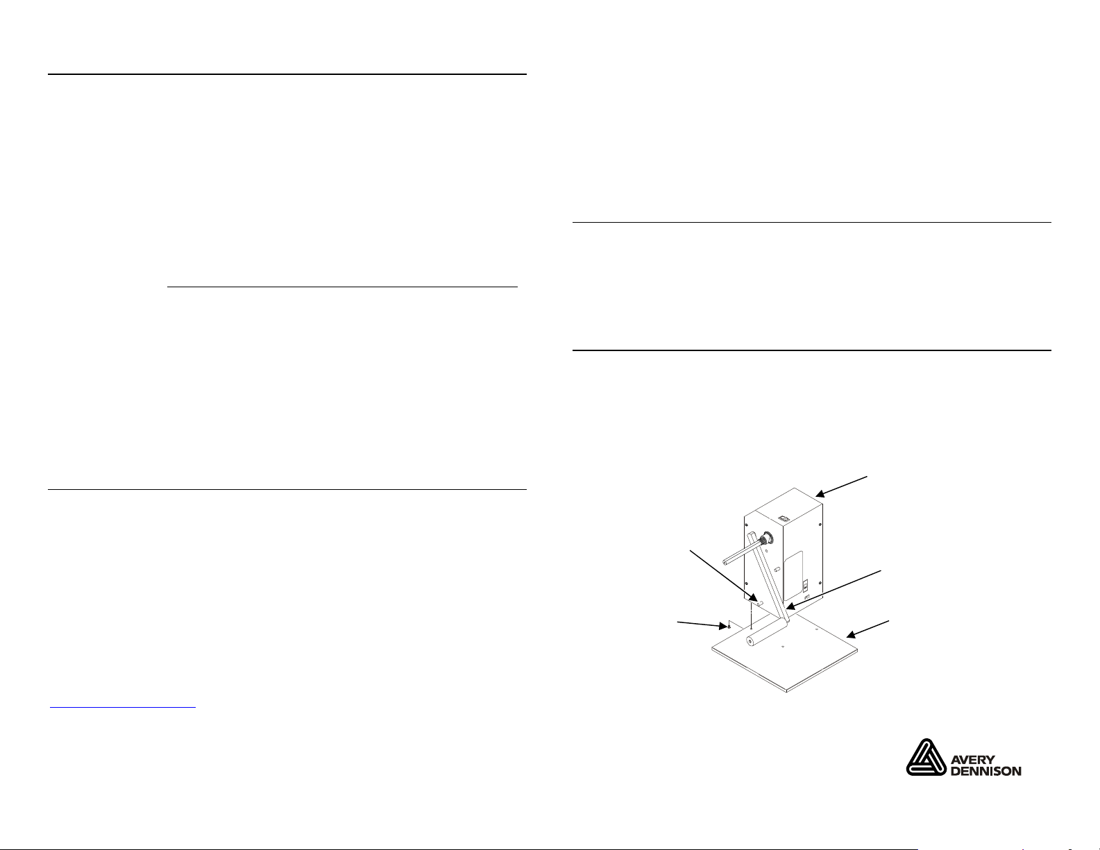
Assembling the Rewinder
To assemble the rewinder, you need a Phillips screwdriver.
1. Line up the holes in the base with the holes in the
bottom of the rewinder.
2. Use the four Phillips screws to attach the base to the
rewinder. The lower pin prevents the pick-up arm from
being assembled on the wrong side of the shaft.
Rewinder
Supply
Thickness:
Supply
Width:
Coreless
0.005 inches to 0.012 inches
(0.13 mm to 0.30 mm)
1.2 inches to 4.125 inches
(30 mm to 105 mm)
1200 inches (30,480 mm)
Maximum:
For supplies, service or assistance, call toll free:
1-800-543-6650 (In the U.S.A.)
1-800-387-4740 (In Canada)
www.monarch.com
Pin
Pick-up arm
Phillips
Screw
Base
CAUTION: Do not lift or carry the rewinder using
the pick-up arm.
Monarch and 935 are trademarks of Avery Dennison
Retail Information Services LLC.
TC0935OI Rev. AF 10/10 2007 Avery Dennison Corp. All rights reserved.
Page 2
Setting Up the Rewinder
The rewinder includes either 3 inc h or 4-inch core holders
standard. The optional Core Kit (PN1244 76) includes 1-inch
and 3-inch core holders, a spindle and bale for coreless
operation. Order the Core Kit to match the core sizes you
need.
1. Slide a disk onto the shaft. Make sure the disk rests on
the small ridge on the s haft.
2. Select the core holder with the small metal clips on the
edge.
3. Slide and thread the core holder onto the shaft with the
beveled edge towards the empty core.
Note: The shaft is threaded and only the core holder wi th
the metal clips threads onto the shaft.
4. Slide an empty core onto the shaft. Make sure it rests
firmly on the core holder.
5. Slide the outer disk onto the retainer. Make sure the
disk rests on the small ri dge on the retainer. Thread the
retainer into the core holde r, tighten and slide onto the
shaft. Make sure the beveled edge of the core holder
fits into the empty core.
6. Align and tighten the thumbscrew with the flat on the
shaft to the outer disk. Do not push the outer disk in
too far.
Troubleshooting
Use the following table to c orrect some minor problems that
may occur.
Problem Action
Rewinder feeds
supply, instead of
rewinding.
The core does not stay
on the core holder.
Supply is pinched
when rewinding.
Rewinder is pulling too
hard on supply or
supply perforations are
breaking.
Note: Disable the printer’s backfe ed option when using the
rewinder; poor image place ment and/or supply
errors may occur.
Make sure the direction switch is
set properly.
Make sure the inside core holder
is the one with the small me tal
clips on the edge.
Make sure the outer disk has not
been pushed in too far.
Make sure the supply is fed
under the pick-up arm and then
attached to the empty core or
coreless adapter.
Shaft
Disk
Empty Core
Retainer
Thumbscrew
Core Holders
Outer Disk
2 7
Page 3

Removing the Supply
Connecting the Cables
1. Loosen the thumbscrew on the ou ter disk.
2. Remove the outer disk and core ho lder.
3. Remove the roll of rewound supplies.
Setting Up for Coreless Operation
The rewinder includes 3 inch or 4-inch core holders
standard. Set up is the same when using the optiona l core
holders for 1-inch or 3-inch operation, see “Setting Up the
Rewinder.”
Note: The maximum number of inches to rewind with the
coreless adapter is 1200.
For coreless operation:
1. Slide a disk onto the shaft. Make sure the disk rests on
the small ridge on the s haft.
2. Remove the bale from the coreless adapter. Slide the
threaded end of the coreless adapter onto the shaft.
3. Tighten the coreless adapter onto the shaft.
4. Place less than 0.5-inch of supply onto the adapter and
slide the bale onto the adapt er. Make sure the short end
of the bale is on the top.
5. Wind a few labels onto the adapt er.
6. Turn on the rewinder.
When finished rewinding, remove the bale and slide the roll
of rewound supplies off the shaft.
1. Plug the power supply into the inlet.
2. Plug the power cable into the power supply.
OFF
ON
Direction
Switch
Power
Inlet
Power Cable
3. Plug the other end of the cable into a grounded electrical
outlet.
4. Turn on the rewinder.
6 3
Page 4

Using the Rewinder
The rewinder can be set for inside (l abels wound in) or
outside (labels wound out) wind ing.
If the full roll of supply was wound face out, it sho uld be
rewound face out; if the full roll of supply was wound face in,
it should be rewound face in.
The winding direction switch is located directly above the
power inlet.
For outside winding:
1. Slide the direction switch t o the lower position.
2. Position and align the rewinder with the printer.
3. Thread the supply as shown.
Direction
Switch
Power
Inlet
Rewinder
Printer
Note: Feed the supply under the pick-up arm.
4. Tape the supply to the empty c ore.
5. Turn on the rewinder.
For inside winding:
1. Slide the direction switch to the upper position.
2. Position and align the rewinder with the printer.
3. Thread the supply as shown.
Rewinder
Note: Feed the supply under the pick-up arm.
4. Tape the supply to the empty c ore.
5. Turn on the rewinder.
Printer
4 5
 Loading...