

Page 1
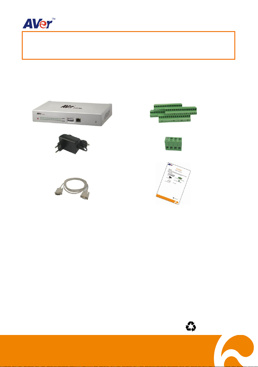
E-I/O Box
4 terminal block for sensor and relay interface
Power Adapter
Terminal block for RS-485 interface
DB9 RS-232 cable
Quick User Guide
E-I/O Box
Quick User Guide
P/N: 300AC0SR-DNL
July 2011
Introduction
With the E-I/O Box, you can integrate your E-I/O box with the AVer
system. The E-I/O Box provides an extra connection of senor and relay devices.
Package Contents
TM
NV/SA/XR/IWH DVR
1
Page 2
Name
Description
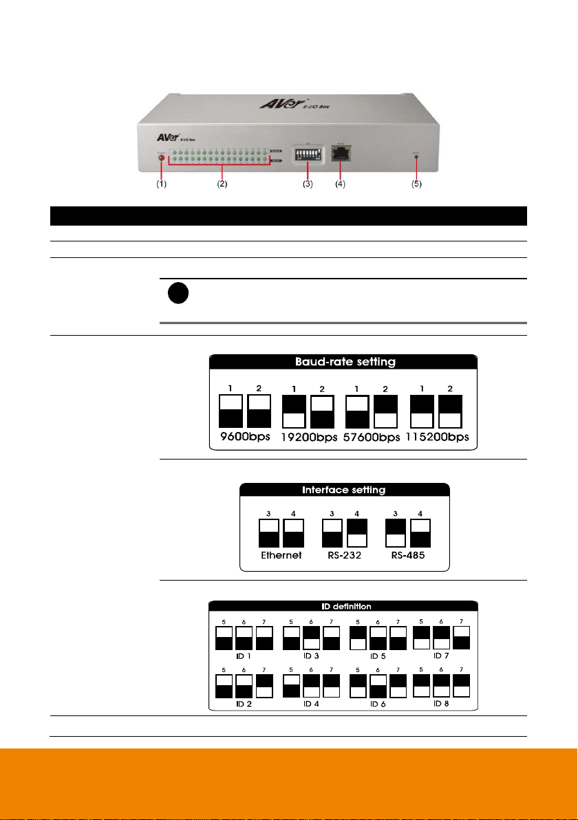
(1) Power LED
Lights when the power is connected
(2) Light indicator
Sensor and relay indicators. Light when the sensor and relay is enabled.
(3) SW
To adjust unit switch appropriate for using condition.
i
- In the figure, black pane represents as the switch position.
- After SW setting, please plug power connector again or
press Reset key to initialize External I/O Box.
(3) SW
Using the DIP switch no.1 & 2 to set the baud-rate setting.
Using the DIP switch no. 3 & 4 to set the type of connection interface.
Using the DIP switch no. 5 ~ 7 to set the ID definition.
(4) RJ-45 port
Ethernet connection
Front Panel
2
Page 3
Name
Description
(5) Reset
To initialize External I/O Box
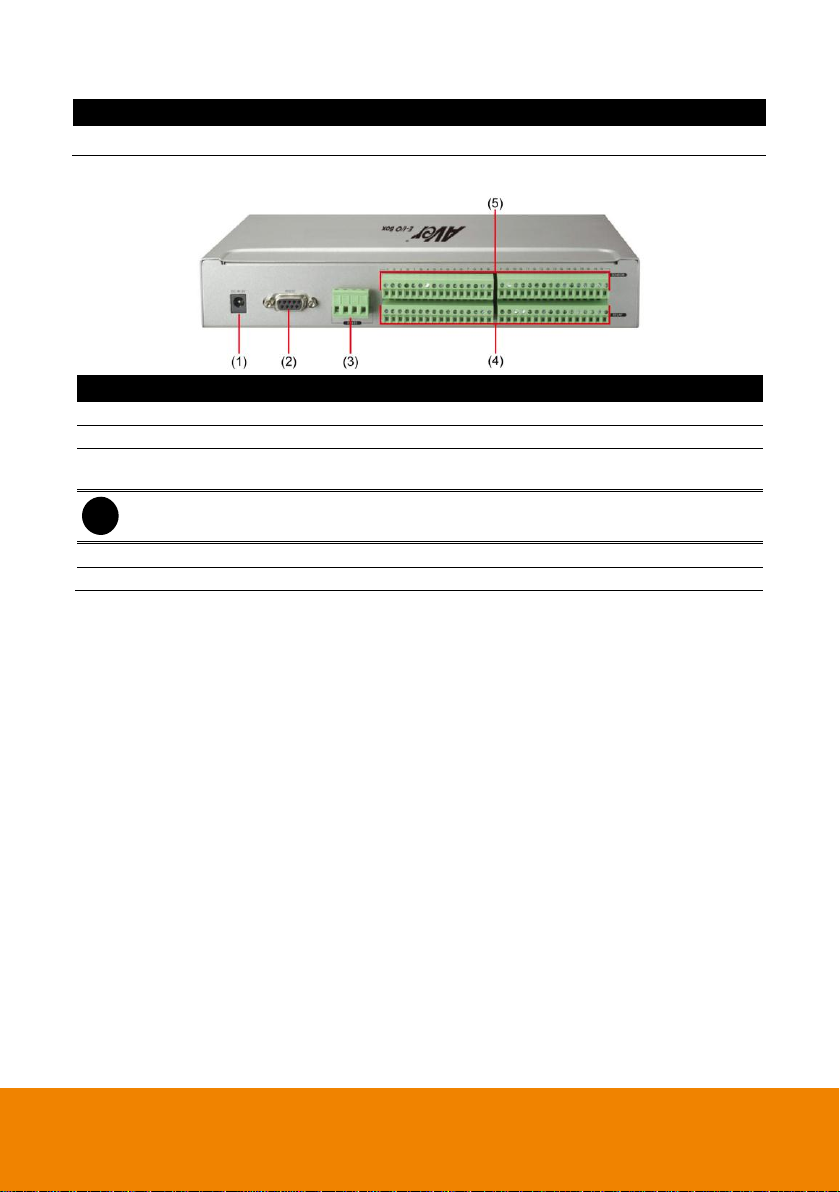
Name
Description
(1) DC IN 5V
Connect the power adapter into this port
(2) RS-232 to DVR
Connect to the COM port of NV/SA/XR/IWH DVR
(3) RS-485
Connect to the COM port of NV/SA/XR/IWH DVR via RS-485 to RS232 converter
i
RS-485 interface doesn’t support to connect with RS-485 interface of SA RACK series
directly.
(4) Relay Out
Connect to the relay device
(5) Sensor In
Connect to the sensor device
Rear Panel
3
Page 4

Pin #
Definition
Pin #
Definition
1
Sensor 1 signal
9
Sensor 9 signal
Sensor G Ground signal
Sensor G Ground signal
2
Sensor 2 signal
10
Sensor 10 signal
Sensor G Ground signal
Sensor G Ground signal
3
Sensor 3 signal
11
Sensor 11 signal
Sensor G Ground signal
Sensor G Ground signal
4
Sensor 4 signal
12
Sensor 12 signal
Sensor G Ground signal
Sensor G Ground signal
5
Sensor 5 signal
13
Sensor 13 signal
Sensor G Ground signal
Sensor G Ground signal
6
Sensor 6 signal
14
Sensor 14 signal
Sensor G Ground signal
Sensor G Ground signal
7
Sensor 7 signal
15
Sensor 15 signal
Sensor G Ground signal
Sensor G Ground signal
8
Sensor 8 signal
16
Sensor 16 signal
Sensor G Ground signal
Sensor G Ground signal
Pin #
Definition
Pin #
Definition
1
Relay Common 1
9
Relay Common 9
Relay Normal Open 1
Relay Normal Open 9
2
Relay Common 2
10
Relay Common 10
Relay Normal Open 2
Relay Normal Open 10
3
Relay Common 3
11
Relay Common 11
Relay Normal Open 3
Relay Normal Open 11
4
Relay Common 4
12
Relay Common 12
Relay Normal Open 4
Relay Normal Open 12
5
Relay Common 5
13
Relay Common 13
Relay Normal Open 5
Relay Normal Open 13
6
Relay Common 6
14
Relay Common 14
Relay Normal Open 6
Relay Normal Open 14
7
Relay Common 7
15
Relay Common 15
Relay Normal Open 7
Relay Normal Open 15
8
Relay Common 8
16
Relay Common 16
Relay Normal Open 8
Relay Normal Open 16
Sensor pinhole allocation
Relay pinhole allocation
4
Page 5

i
Before connect E-I/O Box to DVR system, please remember to plug terminal block
into RS-485, senor, and relay interface.
Making the Connection
E-I/O Box supports serial port to connect to DVR system. If the distance between E-I/O Box and
DVR system is more than 10 meter, we suggest connecting the DVR system through RS-485.
Just follow the illustrated connection below:
Connecting to Surveillance System
Make sure DIP switch no.3 is ON and no.4 is OFF.
Make sure DIP switch no.3 is OFF and no.4 is ON.
5
Page 6

i
- In multiple E-I/O Boxes connection, please set ID number to each E-I/O Box. The EI/O Box connects to DVR system will be ID # 1.
- Please set the interface type for multiple E-I/O Boxes connection, the one
connected to DVR system is RS-232 and rest is RS-485.
- How to set the ID number and interface type, please refer to the figure chart at the
bottom of the E-I/O Box or refer to Front Panel section of this quick guide.
Make sure DIP switch no.3 is ON and no.4 is ON.
Connecting Multiple E-I/O Box
You may connect up to 8 E-I/O Box to DVR system at the same time.
6
Page 7

Setting E-I/O Box Configuration
To set the E-I/O Box setting:
1. Run the DVR program.
2. In the Preview/Advanced screen mode, click .
3. When the DVR configuration setup selection appears, click Sensor or Relay.
4. In the Sensor or Relay Setting dialog box, click External IO button.
Sensor Setting UI Relay Setting UI
5. In the External I/O Setup windows, click Add to set an E-I/O Box, Modify to change the EI/O Box setting, and Delete to remove the selected E-I/O Box. Click Exit to save and close
External I/O Setup windows.
7
Page 8
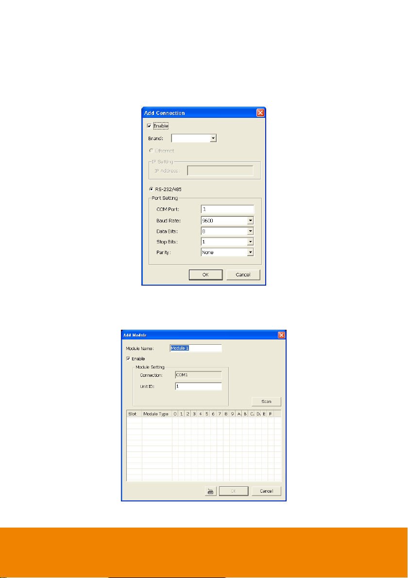
6. In the Add Connection windows, mark Enable box to enable this E-I/O Box.
7. Select the Brand of E-I/O Box from drag down list.
8. In Port Setting, use the default value.
9. Click OK to save the setting and Cancel to exit without saving the new setting
10. To add more than one E-I/O Box, click Add and follow the above step 5~9.
11. In E-I/O Box setup dialog, it will list all added External I/O. Select added E-I/O box and click
Add to enter Add Module window for scanning all connected sensors and relays.
12. In Add Module windows, click Scan to scan the connected relays and sensors on the E-I/O
Box.
8
Page 9

13. All connected relays and sensors will be listed. User can click radio button to change relays’
status. And then, click OK to save the setting and click Cancel to exit and without saving.
14. All connected E-I/O Box and their modules will be listed as tree topology in External I/O
Setup windows.
9
Page 10
© 2011 AVer Information Inc. All rights reserved.
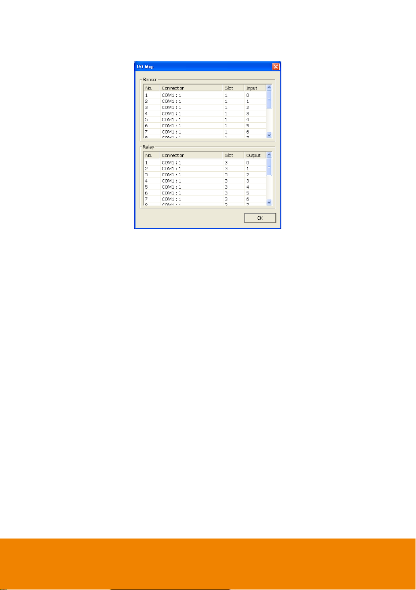
15. To view the all I/O devices information, click I/O Map.
10
 Loading...