

Page 1

Configuring IPsec Services
BayRS Version 13.20
Site Manager Software Version 7.20
Part No. 304111-B Rev 00
April 1999
Page 2

Bay Networ ks, Inc.
4401 Great America Parkway
Santa Clara, CA 95054
Copyright © 1999 Bay Networks, Inc.
All rights reserved. Printed in the USA. April 1999.
The information in this document is subject to change without notice. The statements, configurations, technical data,
and recommendations in this document are believed to be accurate and reliable, but are presented without express or
implied warranty. Users must take full responsibility fo r th eir a pplic a tio ns of any products specified in this document.
The information in this document is proprietary to Bay Networks, Inc.
The software described in this document is furnished under a license agreement and may only be used in accordance
with the terms of that licen se. A summary of the Software License is included in this document.
Trademarks
AN, BN, and Bay Networks are registered trademarks and Advanced Remote Node, ARN, ASN, BayRS, BayStack,
and System 5000 are trademarks of Bay Networks, Inc.
All other trademarks and registered trademarks are t he property of their respective owners.
Restricted Rights Legend
Use, duplication, or disclosure by the United States Government is subject to restrictions as set forth in subparagraph
(c)(1)(ii) of the Rights in Technical Data and Computer So ftware clause at DFARS 252.227-7013.
Notwithstanding any other license agreement that may pertain to, or accompany the delivery of, this computer
software, the rights of the United States Government regarding its use, reproduction, and disclosure are as set forth in
the Commercial Computer Software-Restricted Rights cl ause at FAR 52.227-19.
Statement of Conditions
In the interest of improving internal design, operational function, and/or reliability, Bay Networks, Inc. reserves the
right to make changes to the pr oducts described in this document without notice.
Bay Networks, Inc. does not assume any liability that may occur du e to the use or application of the product(s) or
circuit layout(s) described herein.
Portions of the code in this software product may be Copyright © 1988, Regents of the University of California. All
rights reserved. Redistribution and use in source and binary forms of such portions are permitted, provided th at the
above copyright notice and this paragraph are duplicated in all such forms and that any documentation, advertising
materials, and other materials related to such distribution and use acknowledge that su ch portions of the software were
developed by the University of California, Berkeley. The name of the University may not be used to endorse or
promote products derived from such portions of the software without specific prior written permission.
SUCH PORTIONS OF THE SOFTWARE ARE PROVIDED “AS IS” AND WITHOUT ANY EXPRESS OR
IMPLIED WARRANTIES, INCLUDING, WITHOUT LIMITATION, THE IMPLIED WARRANTIES OF
MERCHANTABILITY AND FITNESS FOR A PARTICULAR PURPOSE.
In addition, the program and information contained herein are licensed only pursuant to a license agreement that
contains restrictions on use and disclosure (that may incorporate by reference certain limitations and notices imposed
by third parties).
ii
304111-B Rev 00
Page 3

Bay Networks, Inc. Software License Agreement
NOTICE: Please carefully read this license agre ement before copying or using the accompanying software or
installing the hardware unit with pre-enabled software (each of which is referred to as “Software” in this Agreement).
BY COPYING OR USING THE SOFTWARE, YOU ACCEPT ALL OF THE TERMS AND CONDITIONS OF
THIS LICENSE AGREEMENT. THE TERMS EXPRESSED IN THIS AGREEMENT ARE THE ONLY TERMS
UNDER WHICH BAY NETWORKS WILL PERMIT YOU TO USE THE SOFTWARE. If you do not accept these
terms and conditions, return the product, unused and in the original shipping container, within 30 days of purchase to
obtain a credit for the full purchase price.
1. License Grant. Bay Networks, Inc. (“Bay Networks”) grants the end user of the Software (“Licensee”) a personal,
nonexclusive, nontransferable license: a) to use the Software either on a single computer or, if applicable, on a single
authorized device identified by host ID, for which it was originally acquired; b) to copy the Software solely for backup
purposes in support of authorized use of the Software; and c) to use and copy the associated user manual solely i n
support of authorized use of the Software by Licensee. This license applies to the Software only and does not extend
to Bay Networks Agent software or other Bay Networks software pro ducts. Bay Networks Agent software or other
Bay Networks software products are licensed for use under the terms of the applicable Bay Networks, Inc. Software
License Agreement that accomp anies such software and upon payment by the end user of the applicable license fees
for such software.
2. Restrictions on use; reservation of rights. The Software and user manuals are protected under copyright laws.
Bay Networks and/or it s licensors retain all title and ownership in both the Software and user manuals, including any
revisions made by Bay Networks or its licensors. The copyright notice must be reproduced and included with any
copy of any portion of the Software or user manuals. Licensee may not modify, translate, decompile, disassemble, use
for any competitiv e analysis, re v erse engineer , distrib ute, or create deriv ati ve works from the Softwa re or user manuals
or any copy, in whole or in part. Except as expressly provided in thi s Agreement, Licensee may not copy or transfer
the Software or user manuals, in whole or in part. The Soft ware and user manuals embody Bay Networks’ and its
licensors’ confidential and proprietary intellectual property. Licensee shall not sublicense, assign, or otherwise
disclose to any third party the Software, or any information about the operation, design, performance, or
implementation of the Software and user manuals that is confidential to Bay Networks and its licensors; however,
Licensee may grant permission to its consultants, subcontractors, a nd agents to use the Softw are at Licensee’s facility ,
provided they have agreed to use the Software only in accordance with the terms of this license.
3. Limited warranty. Bay Netw o r ks wa r ra nts ea c h item of So ft ware, as delivered by Bay Networks and properly
installed and operated on Bay Networks hardware or other equipment it is originally licensed for, to function
substantially as described in its accompanying user m anual during its warranty period , which begins on the date
Software is first shipped to Licensee. If an y item of S oftware f ails to so function d uring its w arranty period, as the sole
remedy Bay Networks will at its discretion provide a suitable fix, patch, or workaround for the problem that may be
included in a future Software release. Bay Network s fur ther w arra nts to Licen see that the medi a on which the
Software is provided will be free from defec ts in materials and wo rkman ship under no rmal use for a peri od of 90 da ys
from the date Software is first shipped to Licensee. Bay Networks will replace defective media at no cha rge if it is
returned to Bay Netw orks during the warran ty perio d alon g with proof of the date of shipment . This war ranty do es not
apply if the media has been dam aged as a resul t of acci dent, misuse , or ab use. The Licen see assumes all re sponsibilit y
for selection of the Software to achieve Licensee’s intended results and for the installation, use, and results obtained
from the Software. Bay Networks does not warrant a) that the functions contained in the software will meet the
Licensee’ s requireme nts, b) that the Software will operate in the hardware or software combinations tha t the L icens ee
may select, c) that the operation of the Softw a re will be uninterru pte d or error free, or d) that all defec ts in the
operation of the Software will be corrected. Bay Networks is not obligated to remedy any Software defect that cannot
be reproduced with the latest Software release. These warranties do not apply to the So ftw are if i t has been (i) altered,
except by Bay Networks or in accordance with its instructions; (ii) used in conjunction with another vendor’s product,
resulting in the defect; or (iii) damaged by improper environment, abuse, misuse, accident, or negligence. THE
FOREGOING WARRANTIES AND LIMITATIONS ARE EXCLUSIVE REMEDIES AND ARE IN LIEU OF ALL
OTHER WARRANTIES EXPRESS OR IMPLIED, INCLUDING W ITHOUT LIMITATION ANY WARRANTY OF
MERCHANTABILITY OR FITNESS FOR A PARTICULAR PURPOSE. Licensee is responsible for the security of
304111-B Rev 00 iii
Page 4

its own data and information and for maintaining adequate procedures apart from the Software to reconstruct los t or
altered files, data, or programs.
4. Limitation of liability. IN NO EVENT WILL BAY NETWORKS OR ITS LICENSORS BE LIABLE FOR ANY
COST OF SUBSTITUTE PROCUREMENT; SPECIAL, INDIRECT, INCIDENTAL, OR CONSEQUENTIAL
DAMAGES; OR ANY DAMAGES RESULTING FROM INACCURATE OR LOST DATA OR LOSS OF USE OR
PROFITS ARISING OUT OF OR IN CONNECTION WITH THE PERFORMANCE OF THE SOFTWARE, EVEN
IF BAY NETWORKS HAS BEEN ADVISED OF THE POSSIBILITY OF SUCH DAMAGES. IN NO EVENT
SHALL THE LIABILITY OF BAY NETWORKS RELATING TO THE SOFTWARE OR THIS AGREEMENT
EXCEED THE PRICE PAID TO BAY NETWORKS FOR THE SOFTWARE LICENSE.
5. Government Licensees. This provision applies to a ll Softwa re and docum entation acquired d irectly or i ndirectly by
or on behalf of the United States Government. The Software and documentation are commercial products, licensed on
the open market at market prices, and were developed entirely at private expense and without th e use of any U.S.
Government funds. The license to the U.S. Government is granted only with restricted rights, and use, duplication, or
disclosure by the U.S. Government is subject to the restrictions set forth in subparagraph (c)(1) of the Commercial
Computer Software––Restricte d Rig hts cla u se o f FAR 52.227-19 and the limita tio ns set o ut in this license for civilian
agencies, and subparagraph (c)(1)(ii) of the Rights in Technical Data and Computer Software clause of DFARS
252.227-7013, for agencies of t he Department of Defense or their successors, whichever is applicable.
6. Use of Software in the European Community. This provision applies to all Software acquired for use within the
European Community. If Licensee uses the Software within a country in the European Community, the Software
Directive enacted by the Council of European Communities Directive dated 14 Ma y, 1991, will apply to the
examination of th e Software to facilitate interoperability. Licensee agrees to notify Ba y Networks of any such
intended examination of the Software and may procure support and assistance from Bay Networks.
7. Term and termination. This license is effective until terminated; however, all of the restrictions with respect to
Bay Networks’ copyright in the Software and user manuals will cease being effective at the date of expiration of the
Bay Networks copyright; those restrictions relating to use and disclosure of Bay Networks’ confidential information
shall continue in effect. Licensee may terminate this license at any time. The license will automatically terminate if
Licensee fails to comply with any of the terms and conditions of the license. Upon termination for any reason,
Licensee will immediately destroy or return to Bay Networks the Software, user manuals, and all copies. Bay
Networks is not liable to Licensee for damages in any form solely by reason of the termination of this license.
8. Export and Re-export. Licensee agrees not to export, directly or indirectly, t he S oft ware or re lated technical data
or information without first obtaining any required export licenses or other governmental approvals. Without limiting
the foregoing, Licensee, on behalf of itself and its subsidiaries and affiliates, agrees that it will not, without first
obtaining all export licenses and approvals required by the U.S. Government: (i) export, re-export, transfer, or divert
any such Software or technical data, or any direct product thereof, to any country to which such exports or re-exports
are restricte d or em b argoed under United States ex po r t con t rol laws and re gulations, or to any national or resident of
such restricted or embargoed countries; or (ii) provide the Software or related technical data or information to any
military end user or for any military end use, including the design, development, or production of any chemical,
nuclear, or biological weapons.
9. General. If any provision of this Agreement is held to be invalid or unenf orceable by a court of competent
jurisdiction, the remainder of the provisions of this Agreement shall remain in full force and effect. This Agreement
will be governed by the laws of the state of California.
Should you have any questions concerning this Agreement, contact Bay Networks, Inc., 4401 Great America Parkway,
P.O. Box 58185, Santa Clara, California 95054-8185.
LICENSEE ACKNOWLEDGES THAT LICENSEE HAS READ THIS AGREEMENT, UNDERSTANDS IT, AND
AGREES TO BE BOUND BY ITS TERMS AND CONDITIONS. LICENSEE FURTHER AGREES THAT THIS
AGREEMENT IS THE ENTIRE AND EXCLUSIVE AGREEMENT BETWEEN BAY NETWORKS AND
LICENSEE, WHICH SUPERSEDES ALL PRIOR ORAL AND WRITTEN AGREEMENTS AND
COMMUNICATIONS BETWEEN THE PARTIES PERTAINING TO THE SUBJECT MATTER OF THIS
AGREEMENT. NO DIFFERENT OR ADDITIONAL TERMS WILL BE ENFORCEABLE AGAINST B AY
NETWORKS UNLESS BAY NETWORKS GIVES ITS EXPRESS WRITTEN CONSENT, INCLUDING AN
EXPRESS WAIVER OF THE TERMS OF THIS AGREEMENT.
iv 304111-B Rev 00
Page 5

Contents
Preface
Before You Begin .............................................................................................................xiii
Text Conventions .............................................................................................................xiv
Acronyms ........................... .......................... .......................... ......................... ................. xv
Bay Networks Technical Publications .............................................................................xvii
How to Get Help .............................................................................................................xvii
Chapter 1
Overview of IPsec
About IPsec .... ...... ...... ....... ...... ....................................... ....... ...... ...... ....... ...... ....... ...... ...1-2
IPsec Services ................................................................................................................1-2
Confidentiality ....... ....... ...... ....... ...... ....... ...... ....... ...... ....... ...... ...... ....... ...... ....... ...... ...1-2
Integrity ....................................................................................................................1-3
Authentication ..........................................................................................................1-3
Additional IPsec Services ........................................................................................1-3
How IPsec Works ...........................................................................................................1-3
IPsec Protection .......................................................................................................1-4
IPsec Tunnel Mode ...................................................................................................1-5
Elements of IPsec ...........................................................................................................1-5
Security Gateways ..........................................................................................................1-7
Security Policies .............................................................................................................1-8
Policy Templates ......................................................................................................1-8
Inbound Policies .......................................................................................................1-9
Outbound Policies ....................................................................................................1-9
Policy Criteria Specification ....................................................................................1-10
Security Associations ...................................................................................................1-11
Automated Security Associations Using Internet Key Exchange (IKE) ..................1-11
Manual Security Associations ................................................................................1-12
Security Associations for Bidirectional Traffic .........................................................1-12
304111-B Rev 00 v
Page 6

How IKE Negotiates Security Associations ............................................................1-13
Security Parameter Index (SPI) ..............................................................................1-13
Summarizing Security Policies and SAs .......................................................................1-14
Security Protocols .........................................................................................................1-15
Encapsulating Security Payload .............................................................................1-15
Authentication Header ............................................................................................1-16
Internet Key Exchange (IKE) Protocol ..........................................................................1-17
Perfect Forward Secrecy ........................................................................................1-17
Network Requirements for Bay Networks Routers .......................................................1-18
Supported Routers .................................................................................................1-18
Supported WAN Protocols .....................................................................................1-18
Chapter 2
Getting Started With IPsec
Upgrading Router Software ............................................................................................2-2
Installing the IPsec Software ................................................. ...... ...... ....... ...... ....... ...... ...2-2
Completing the Installation Process ..................................................................2-3
Installing Triple DES Encryption ...............................................................................2-3
Securing Your Site ..........................................................................................................2-4
Securing Your Configuration ...........................................................................................2-4
Encryption Keys .......................................................................................................2-4
Random Number Generator (RNG) .........................................................................2-5
Creating a Node Protection Key (NPK) ..........................................................................2-5
Generating NPKs .....................................................................................................2-5
Entering an Initial NPK and a Seed for Encryption .........................................................2-6
Changing an NPK ....................................................................................................2-8
Monitoring NPKs ......................................................................................................2-8
Chapter 3
Configuring IPsec
Enabling IPsec and IKE ........... ....... ...... ....... ...... ....... ...... ....... ...... ...... ....... ......................3-1
Creating Policies .............................................................................................................3-2
Specifying Criteria ....................................................................................................3-2
Specifying an Action .................................................................................................3-3
Policy Considerations ...............................................................................................3-3
Creating an Outbound Policy ...................................................................................3-4
vi 304111-B Rev 00
Page 7

Creating an Inbound Policy ......................................................................................3-6
Creating Security Associations .......................................................................................3-8
About Automated SA Creation ........................... ...... ....... ...................................... ...3-8
About Manual SA Creation .......................................................................................3-8
Creating a Protect SA Automatically Using IKE .......................................................3-9
Creating an Unprotect SA Automatically Using IKE ...............................................3-10
Creating a Protect SA Manually .............................................................................3-11
Creating an Unprotect SA Manually .......................................................................3-12
Disabling IPsec .................. ...... ....... ...... ....... ...... ....................................... ...... ....... ...... .3-13
Appendix A
Site Manager Parameters
Node Protection Key Para meter .................................................................................... A-1
Enabling IPsec Parameters ........................................................................................... A-2
IPsec Policy Parameters ................................................................................................ A-3
Manual Security Association Parameters ...................................................................... A-4
Automated Security Association (IKE) Parameters ....................................................... A-9
Appendix B
Definitions of k Commands
Appendix C
Configuration Examples
Inbound and Outbound Policies .....................................................................................C-1
Automated SA (IKE) Policy Examples ..................................................................... C-2
Manual SA Policy Examples ...................................................................................C-5
Manual Protect and Unprotect SA Configuration ........................................................... C-9
Appendix D
Protocol Numbers
Assigned Internet Proto co l Number by Name ....................................................... ...... .. D-2
Assigned Internet Protocol Numbers by Number .......................................................... D-6
Index
304111-B Rev 00 vii
Page 8

Page 9

Figures
Figure 1-1. IPsec Environment: Unique Security Associations (SAs)
Between Routers .....................................................................................1-4
Figure 1-2. IPsec Concepts: Security Gateways, Security Policies, and SAs ............1-6
Figure 1-3. IPsec Security Gateways and Security Policies .......................................1-7
Figure 1-4. Security Associations for Bidirectional Traffic .........................................1-12
Figure C-1. IPsec Automated Outbound Policies for RTR1, RTR2, and RTR3 ..........C-2
Figure C-2. IPsec Manual Outbound Policies for RTR1, RTR2, and RTR3 ...............C-5
Figure C-3. Single Protect/Unprotect SA Pair ............................................................ C-9
Figure C-4. Multiple Protect/Unprotect SA Pairs ...................................................... C-12
304111-B Rev 00 ix
Page 10

Page 11

Tables
Table 1-1. Security Policy Specifications ................................................................1-14
Table 1-2. Manual Security Association (SA) Configurations .................................1-15
Table D-1. Internet Protocol Numbers, Sorted by Acronym .................................... D-2
Table D-2. Internet Protocol Numbers, Sorted by Number ......................................D-6
304111-B Rev 00 xi
Page 12

Page 13

This guide describes the Bay Networks® implementation of IP Security and how
to configure it on a Bay Networks router.
Before You Begin
Before using this guide, you must complete the following procedures. For a new
router:
• Install the router (see the installation guide that came w ith your router).
• Connect the router to the network and create a pilot configuration file (see
Quick-Starting Routers or Configuring BayStack Remote Access).
Preface
Make sure that you are running the latest version of Bay Networks BayRS
Site Manager software. For information about upgrading BayRS and Site
Manager, see the upgrading guide for your version of BayRS.
304111-B Rev 00 xiii
™
and
Page 14

Configuring IPsec Services
Text Conventions
This guide uses the following text conventions:
angle brackets (< >) Indicate that you choose the text to enter based on the
description inside the brackets. Do not type the
brackets when entering the command.
Example: If the command syntax is:
ping
<
ip_address
ping 192.32.10.12
>, you enter:
bold text
Indicates command names and options and text that
you need to enter.
Example: Enter
show ip {alerts | routes
Example: Use the
dinfo
command.
}.
braces ({}) Indicate required elements in syntax descriptions
where there is more than one option. You must choose
only one of the options. D o not type the braces when
entering the command.
Example: If the command syntax is:
show ip {alerts | routes
show ip alerts or show ip routes
}
, you must enter either:
, but not both.
brackets ([ ]) Indicate optional elements in syntax descriptions. Do
not type the brackets when entering the command.
Example: If the command syntax is:
show ip interfaces [-alerts
show ip interfaces
or
]
, you can enter either:
show ip interfaces -alerts
.
italic text Indicates file and directory names, new terms, book
titles, and variables in command syntax descriptions.
Where a variable is two or more words, the words are
connected by an underscore.
Example: If the command syntax is:
show at
valid_route
<
valid_route
>
is one variable and you substitute one value
for it.
xiv 304111-B Rev 00
Page 15

Preface
screen text Indicates system output, for example, prompts and
system messages.
Acronyms
Example:
Set Bay Networks Trap Monitor Filters
separator ( > ) Shows menu paths.
Example: Protocols > I P ide nti fies the IP option on the
Protocols menu.
vertical line (
) Separates choices for command keywords and
|
arguments. Enter only one of the choices. Do not type
the vertical line when entering the command.
Example: If the command syntax is:
show ip {alerts | routes
show ip alerts
or
This guide uses the following acronyms:
3DES Triple DES
AH authentication header
CBC cipher block chaining
}
, you enter either:
show ip routes
, but not both.
DES Data Encryption Standard
ESP Encapsulating Security Payload
HMAC Hashing Message Authentication Code
IANA Internet Assigned Numbers Authority
ICMP Internet Control Me ssage Protocol
ICV integri ty check value
IETF Internet Engineering Task Force
IKE Internet Key Exchange protocol
IP Internet P rotocol
IPsec Internet Protocol Security
304111-B Rev 00 xv
Page 16

Configuring IPsec Services
ISAKMP/Oakley Internet Security Association and Key Management
IV initialization vector
MD5 Message Digest 5
MIB management information base
NPK node protection key
NVRAM nonvolatile random access memory
PPP Point-to-Point Protocol
RNG random number generator
RSA RSA Data Security, Inc.’s public-key encryption
SA security association
SAD security associations database
SHA Secure Hash Algorithm
SPD security policy database
Protocol (also known as IKE)
algorithm
SPI security parameter index
VPN virtual private network
WAN wide area network
xvi 304111-B Rev 00
Page 17

Bay Networks Technical Publications
You can now print Bay Networks technical manuals and release notes free,
directly from the Internet. Go to support.baynetwork s.com/libr ary/ tpubs/ . Fi nd the
Bay Networks product for which you need documentation. Then locate the
specific category and model or version for your hardware or software product.
Using Adobe Acrobat Re ader, you can open the manuals an d rel ease n otes, searc h
for the sections you need, and print them on most standard printers. You can
download Acrobat Reader free from the Adobe Systems Web site,
www.adobe.com.
You can purchase Bay N etworks documentation sets, CDs, and selected technical
publications through the Bay Networks Collateral Catalog. The catalog is located
on the World Wide Web at support.baynetworks.com/catalog.html and is divided
into sections arranged alphabetically:
• The “CD ROMs” section lists available CDs.
• The “Guides/Books” section lists books on technical topics.
• The “Technical Manuals” section lists available printed documentation sets.
Preface
Make a note of the part numbers and prices of the items that you want to order.
Use the “Marketing Collateral Catalog description” link to place an order and to
print the order form.
How to Get Help
For product assi stance, support contracts, information abo ut educational services,
and the telephone numbers of our gl obal supp ort offices, go to the following URL:
http://www.baynetworks.com/corpor a te/co ntacts /
In the United States and Canada, you can dial 800-2LANWAN for assistance.
304111-B Rev 00 xvii
Page 18

Page 19
Chapter 1
Overview of IPsec
This chapter descr ibes the emer ging Inte rnet Engineer ing Task Force st andards fo r
security services over public networks, commonly referred to a s IP Security or
IPsec. The chapter also includes information specific to the Bay Networks
implementation of IPsec and requirements for that implementation.
This chapter includes the following information:
Topic Page
304111-B Rev 00
About IPsec 1-2
IPsec Services 1-2
How IPsec Works 1-3
Elements of IPsec 1-5
Security Gateways 1-7
Security Policies 1-8
Security Associations 1-11
Summarizi ng Security Policies and SAs 1-14
Security Protocols 1-15
Internet Key Exchan ge (IKE) Protocol 1-17
Network Requirements for Bay Networks Routers 1-18
1-1
Page 20

Configuring IPsec Services
About IPsec
IP Security (I Psec) is the Internet Engineering Task Force (IETF) set of emerging
standards for security services for communications over public networks. The
standards are documented in the IETF Requests for Comments (RFCs) 2401
through 2412. Additional RFCs may be relevant as well.
These standards were developed to ensure secure, private communications for the
remote access, extranet, and intranet virtual pr ivate networks (VPNs) used in
enterprise communications. They are the security architecture for the next
generation of IP, called IP v6, but are available for the current IPv4 Internet as
well.
The Bay Networks implementation of the IETF standards provides network
(layer 3) security services for wide area network (WAN) communications on Bay
Networks routers.
IPsec Ser vices
IPsec serv ices consist of confidentiality, integrity, and authentication services for
data packets traveling between security gate ways.
• Confidentiality ensures the privacy of communications.
• The integrity service detects modification of data packets.
• Authentication ser vices verify the origin of every data packet.
Confidentiality
Confidentiality is accomplished by encrypting and decrypting data packets. The
Encapsulating Security Payload (ESP) protocol uses the Data Encryption
Standard (DES) algorithm in cipher block chaining (CBC) mode to encrypt and
decrypt data packets.
You set confidentiality with the cipher algorithm and cipher key parameters. The
cipher algorithm and cipher key are specified in security associat ions (SAs). A
security association is a relationship in which two peers share the necessary
information to secur ely prote ct and unpr otect data. Th e algori thm and ke y must b e
identical on both ends of an IPsec SA.
1-2
304111-B Rev 00
Page 21

Integrity
Integrity determines whether the data has been altered during trans it. The ESP
protocol ensures that data has not been modified as it passes between the security
gateways . The ESP protoco l uses the HMAC MD5 (RFC 2403) or HMAC SHA-1
(RFC 2404) transform.
You set integrit y with the integrity algorithm a nd integrity key parameters. The
integrity algorithm and integrity key must be identical on both e nds of an IPsec
SA.
Authentication
Authentication ensures that data has been transmitted by the identified source.
Additional IPsec Services
Within the IPsec framework, additional security services are provided. An access
control service ensures authorized use of the network, and an auditing service
tracks all actions and events.
Overview of IPsec
IPsec services can be configured on an interface-by-interface basis. Up to 127
inbound and 127 outbound security policies (customized) are supported on each
IPsec interface.
How IPsec Works
IPsec services are bundled as an Internet Protocol (IP) encryption packet. The
packets resemble ordinary IP packets to Internet rout ing nodes; only the sending
and receiving devices are involved in the encryption. IPsec packets are delivered
over the Internet like ordinary IP packets to branch offices, corporate partners, or
other remote organizations in a secure, encrypted, and private manner.
Sever al well-est ablished tech nologies pro vide enc ryption and aut henticatio n at the
application laye r. IPsec adds security at the underlying network layer, providing a
higher degree of secur ity fo r all a ppl icati ons, inc luding those wit hou t an y secur ity
features of their own.
304111-B Rev 00
1-3
Page 22
Configuring IPsec Services
IPsec Protection
To configure a router with IPsec, you first configure the router interface as an
IP interface. Then you add the IPsec software to the IP interface, creating a
security gateway. A security gateway is a router between a trusted network (for
example, the enterprise intranet) and an untrusted network (the Internet) that
provides a security service such as IPsec.
The router interface is secured with inbound and outbound security policies that
filter traffic to and from the router module. The data packets themselves are
protected by IPsec protocol processing specified by security associations (SAs).
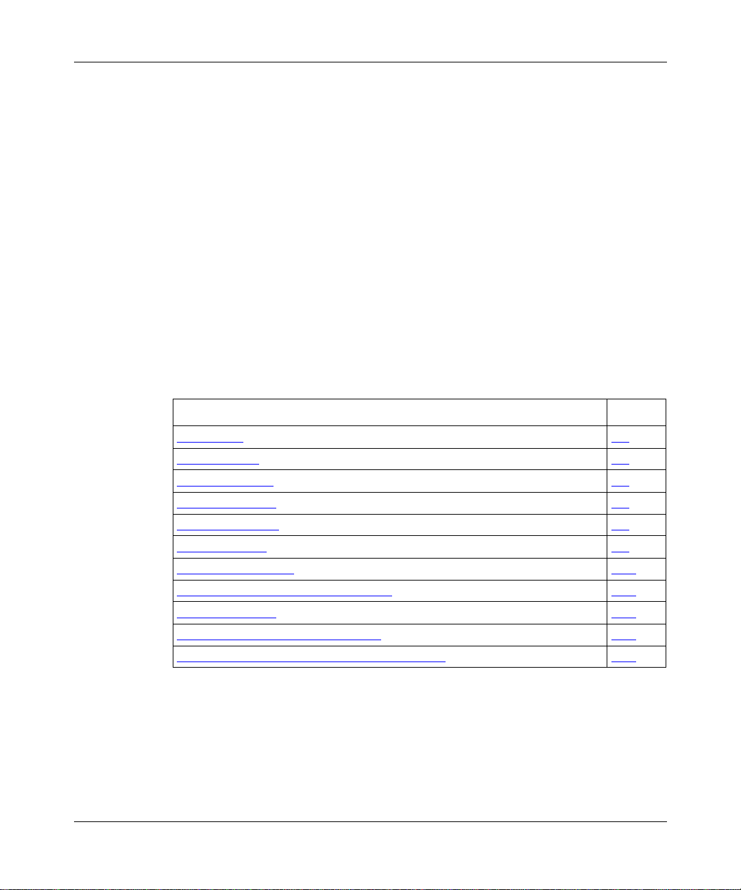
Figure 1-1 sho ws ho w IPsec can prote ct data c ommunication s within a n enterpr ise
and from external hosts.
Corporate
headquarters
Server
Router A
IP security
gateway
Security
associations
(SAs A,B)
Partner
Router B Router C
Host Host
IP security
gateway
IPsec
services
Public
network
Security associations
(SAs B,C)
IPsec
services
Security
associations
(SAs C,A)
Branch office
IP security
gateway
IPsec
services
IP0088A
Figure 1-1. IPsec Environment: Unique Security Associations (SAs)
Between Routers
1-4
304111-B Rev 00
Page 23

IPsec Tunnel Mode
When there is a security gateway at each end of a communication, the security
associations between the gateways are said to be in tunnel mode. The tunnel
metaphor refers to data being visible only at the beginning and end points of the
communication. The IP packets protected by IPsec have regular, “visible” IP
headers, but the packet contents are encrypted, and thus hidden. All BayRS IPsec
communications occur in tunnel mode. Tunnel mode is especially effective for
isolating and prot ecting enterp rise traf f ic tra veli ng across a publ ic data net work, as
shown in Figure 1-1.
Elements of IPsec
IPsec has three important constructs:
• Security gateways
• Security policies
• Security associatio ns (SAs)
Overview of IPsec
304111-B Rev 00
In the IPsec context, hosts communicate across an untrusted network through
security gateways (routers configured for IPsec interfaces). Security policies
determine ho w the IPsec interfaces handle data packets for the hosts on both ends
of a connection. Security associations apply IPsec services to data packets
traveling between the security gateways.
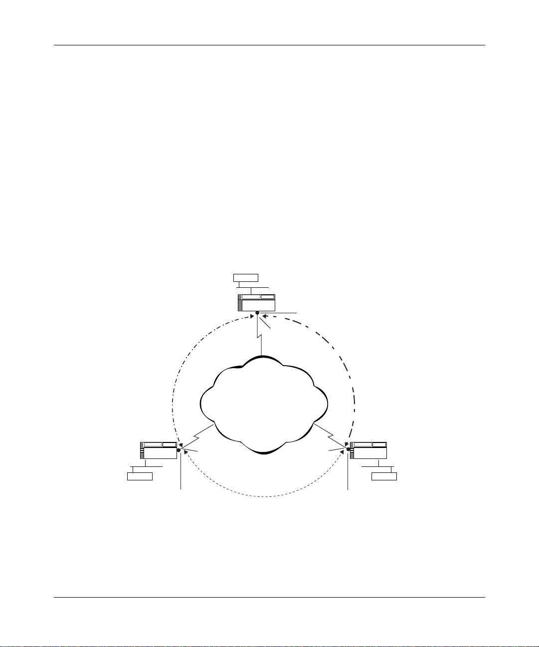
Figure 1-2
associations.
shows the logical relationship between security policies and security
1-5
Page 24
Configuring IPsec Services
Security associations
IPsec gateway WAN interface
Inbound process
Unprotect SAs
Source/Dest Addr, SPI
Cipher Algo/Key,
Integrity Algo/Key
Protect SAs
Source/Dest Addr, SPI
Cipher Algo/Key,
Integrity Algo/Key
Inbound policies
criteria & action
(bypass, drop, log)
Outbound policies
criteria & action
(bypass, drop, log,
protect)
Outbound process
Security
policy
database
Figure 1-2. IPsec Concepts: Security Gateways, Security Policies, and SAs
Untrusted
network
IP00087A
1-6
304111-B Rev 00
Page 25
Security Gateways
A security gateway establishes SAs between router interfaces configured with
IPsec software. A Bay Networks router becomes a security gateway when you
enable IPsec on a WAN interface. In this way, a Bay Networks router operati ng as
a security gateway provides IPsec services to its internal hosts and subnetworks.
Hosts or networks on th e e xte rnal si de of a sec urit y ga te w ay (typic ally, the overall
Internet) are considered “untrusted.” Hosts or subnetworks on the internal side of
a security gat e w ay (nodes on your l ocal i ntra net) are consi dered “trus te d” beca use
they are controlled and securely managed by the same network administration
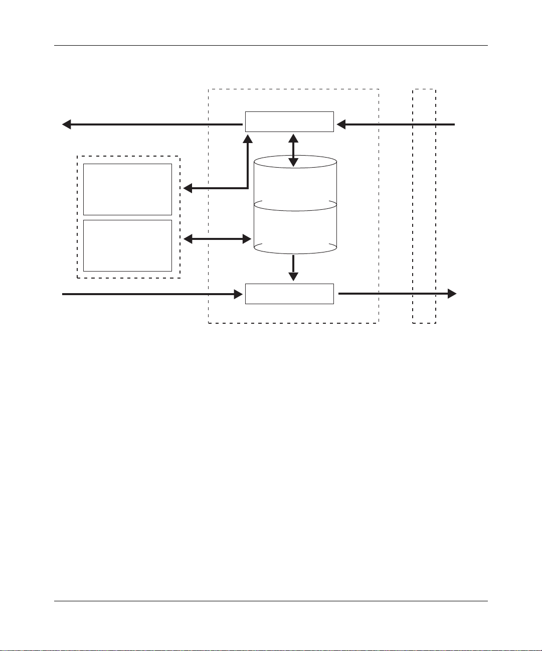
(Figure 1-3
).
Overview of IPsec
Trusted
network
Local
host
Outbound policy
Security
gateway
Inbound policy (clear text only)
IPsec interface
Untrusted
network
IPsec interface
Outbound policy
Security
gateway
Inbound policy (clear text only)
Figure 1-3. IPsec Security Gateways and Security Policies
When you add IPsec services to a router to create a security gateway, its internal
hosts and subnetworks can communicate with external hosts that directly operate
IPsec services, or with a remote security gateway that provides IPsec services for
its set of hosts and subnetworks.
Trusted
network
Remote
host
IP0078A
304111-B Rev 00
1-7
Page 26

Configuring IPsec Services
Security Policies
When you create an IPsec policy, you control which packets a security gateway
protects, how it handles packets to or from particular addresses or in a particular
protocol, and whether it logs information about these actions.
There are two types of IPsec policies: inbound and outbound. An inbound policy
is used for data packets arriving at a security gateway, and an outbound policy is
used for data pa ck ets leaving a security gateway. Each IPsec interface can support
up to 127 inbound and 127 outbound security policies (refer to Figure 1-3
page 1-7
The criteria (“selectors”) and action specifications used in your inbound and
outbound policies are stored in the security policy database (SPD).
IPsec defaults i n fa v or of more securit y rather th an less. I f an outbou nd or inbou nd
packet does not match the criteria of any configured outbound or inbound policy
in the SPD, the packet is dropped.
IPsec discards an y out bound clear-text data packet unle ss you explicitly configure
a policy to bypass or protect it.
).
on
Policy Templates
Every IPsec polic y is ba sed on a policy template. A policy template is a pr edef ined
policy definition that you can use on any IP interface. The template specifies one
or more criteria and an action to apply to incoming or outgoing data packets.
A policy template and every policy based on it must includ e at least one criterion,
for example, an IP source address, and one action. For example, an outbound
policy might specify a pr otect ac tion. A poli cy t emplate or po lic y may inc lude tw o
actions if one of the actions is logging. The criterion specification determines
whether a data pack et matches a pa rticula r securit y polic y, and the action speci fi es
how the policy is applied to the packet.
The action specifications that you can include in inbound and outbound policies
are listed in the two sections that follow.
1-8
304111-B Rev 00
Page 27

Inbound Policies
An inbound policy determines how a security gateway processes data packets
receiv ed from a n u ntrus ted ne tw ork. Ev ery pack e t ar ri v ing at a secu rity g ateway is
compared with the criteria to determine whether it matches an IPsec policy for
that router. If the incoming packet matches a bypass policy, the router accepts the
packet and, if the policy is so configured, logs it.
If the packet d oes n ot mat ch an y poli cy o r matches a drop poli c y, the router rejects
the packet. When a packet does not match any policy, IPsec’s default action is to
drop it.
For an inbound security policy, the action may be:
•Drop
• Bypass
•Log
Drop and bypass are mutua lly e xc lusive. The log action may be a dded t o eit her, or
used alone.
Overview of IPsec
Outbound Policies
An outbound policy determines ho w a se curity gat e way proces ses data pac kets f or
transmission across an untrust ed netwo rk. You must assign an outbound poli cy fo r
all unicast traffic leaving an IPsec interface.
For an outbound policy, the action specification may be:
• Protect
•Drop
• Bypass
•Log
Any outbound policy with a protect action specification is mapped to a Protect
SA. See “
information about Protect and Unprotect SAs.
Drop, protect, and bypass are mutually exclusive. The log action may be added to
any of the three, or used alone.
304111-B Rev 00
Summarizing Security Policies and SAs” on page 1-14 for detailed
1-9
Page 28

Configuring IPsec Services
Policy Criteria Specification
IPsec software inspects IP packet headers based on the specified criteria to
determine whether a policy applies to a data packet.
You must include at least one of the following crit eria, and you may specify all
three criteria in an IPsec policy:
• IP source address
• IP destination address
• Protocol
To specify the protocol criterion, you must provide the numeric value assigned to
the protocol for use o v er the I ntern et. You can specify only a sin gle pr otocol value
for each policy. The protocol number is represented in the 1-byte protocol field in
an IP packet header.
Refer to Appendix D
for a list of protocol numbers. To obtain the most recent list
of the numeric values assigned to various protocols, see the Internet Assigned
Numbers Authority (IANA) Web site at:
http://www.iana.org
The direct path to the list of legal values tha t you can specify for an IP sec policy
protocol criterion as of this printing is:
http://www.isi.edu/in-notes/iana/assignments/protocol -numbers
1-10
304111-B Rev 00
Page 29

Overview of IPsec
Security Associations
A security association (SA) is a relationship in which two peers share the
necessary information to securely protect and unprotect data. An IPsec SA is
uniquely identified by an IP destination addr ess, securit y parameter index (S PI),
and security protocol identifier (for example, ESP in tunnel mode).
An IPsec policy deter mine s which pack et s will be hand le d. An IPsec SA spe cif i es
which IPsec security service (for example, confidentiality) IPsec will apply to the
packets. You can apply one or more IPsec security services.
SAs themselves must be created and shared in a secure manner. There are two
ways of achieving this: by using the automated security negotiation process
provided by the Internet Key Exchange (IKE) protocol; or by manually
configuring the sending and receiving devices with a shared secret. A shared
secret is a unique security identifier.
Automated Security Associations Using Internet Key Exchange (IKE)
Internet Key Exchange (IKE) is an automated protocol to establish security
associations over the Internet. (IKE is also referred to as the Internet Security
Association Key Management Protocol with Oakley Key Determination, or
ISAKMP/Oakley.) IKE handles negot iating, esta blishing, modifying, and deleting
security associations.
304111-B Rev 00
To set up these security associations, IKE itself must create a confidential, secure
connection between the sender and receiver. Authentication is accomplished with
one or more of the following:
• Pre-shared keys: These are set up ahead of time at eac h node in a tr ansact ion.
• Public key cryptography: Using the RSA public key algorithm, each
member of a transaction authenticates itself to the other using the other
member’s public key to encrypt an authentication value.
• Digital signature: Each member of a transaction sends a digital signature to
the other. The signatures are authenticated using the member’s public key,
obtained via an X.509 digital certificate.
The BayRS implementation of IKE uses pre-shared keys only.
1-11
Page 30
Configuring IPsec Services
Manual Security Associations
Manually configuring security associations is a more cumbersome and
labor-intensive process than using IKE. If possible, IKE should be used to make
large-scale secure communications practical.
Manually configured SAs often rely on static, symmetric keys on communicating
hosts or security gate w ays. As such, you must coordina te wit hin your or ganizat ion
and with outside parties to configure keys that will protect your information.
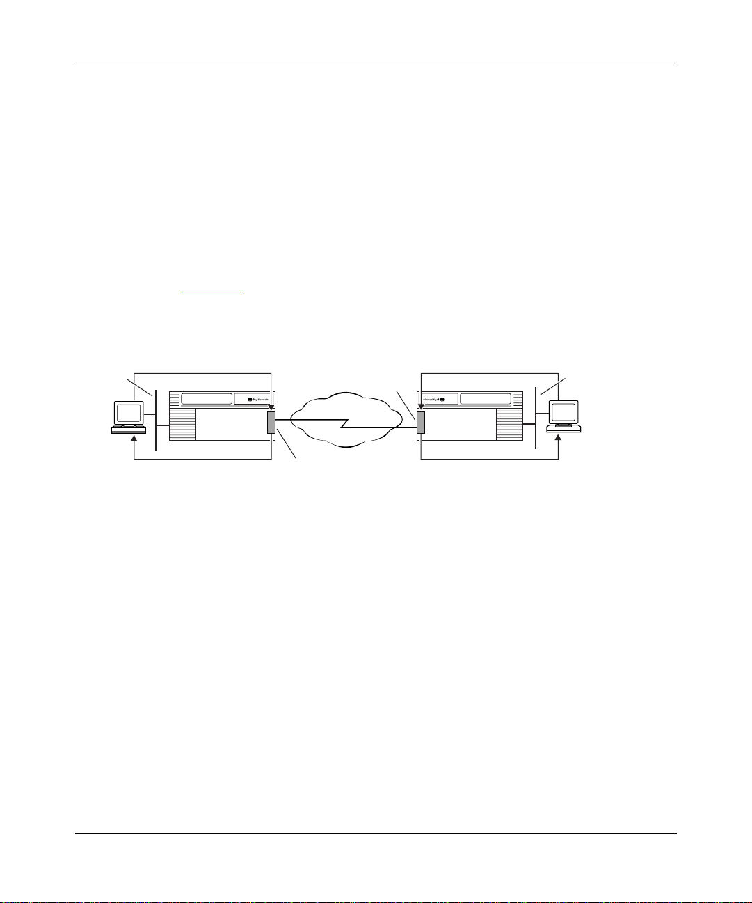
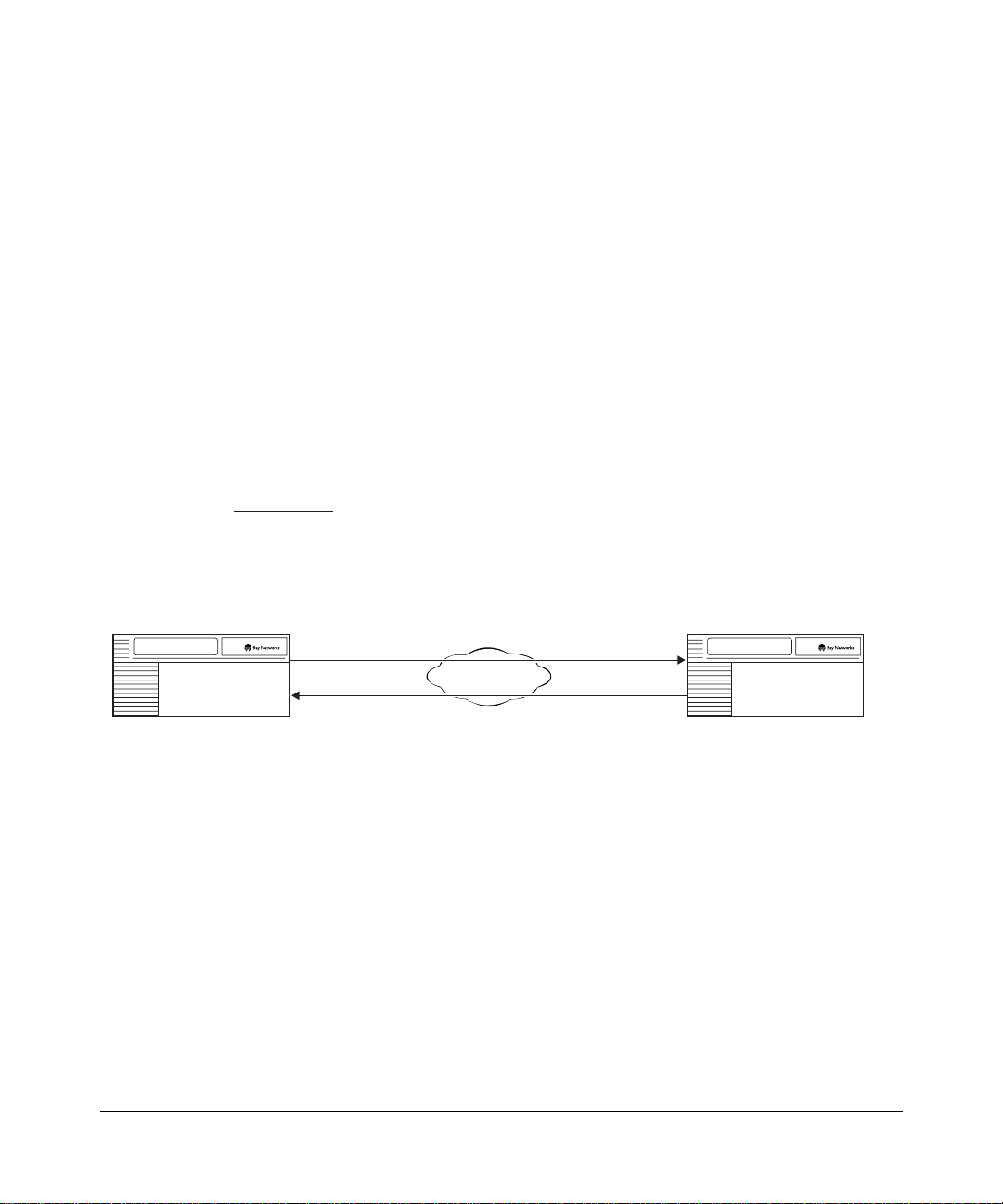
Security Associations for Bidirectional Traffic
An SA specifies the security services that are applied to data packets traveling in
one direction between security gateways. To secure the traffic in both directions,
the security gateway must have a Protect SA for data transmitted from the local
IPsec interface and an Unprotect SA for data received by the local IPsec interface
(Figure 1-4)
.
Protect SA
Source: 132.245.145.195
Security gateway Security gateway
132.245.145.195
Destination: 132.245.145.205
Unprotect SA
Source: 132.245.145.205
Destination: 132.245.145.195
Unprotect SA
Source: 132.245.145.195
Destination: 132.245.145.205
Network
Protect SA
Source: 132.245.145.205
Destination: 132.245.145.195
Figure 1-4. Security Associations for Bidirectional Traffic
Under most circumstances, you will configure the Internet Key Exchange (IKE)
protocol to negotiate SAs between security gateways automatically. You can also
manually config ure SAs.
132.245.145.205
IP0079A
1-12
304111-B Rev 00
Page 31

How IKE Negotiates Security Associations
The Internet Key Exchange (IKE) protocol automates the process of IPsec SA
configuration by creating an IKE SA for Protect SA and Unprotect SA
negotiatio n. Each IKE peer sends IPsec SA para meter ne gotiation in formation in a
secure IKE packet. The peers generate keys based on the agreed parameters and
then verify each other’s identity. Once this is done, the IPsec SA is established.
The IKE protocol itself is secured through an IKE SA created using the
Diffie-Hellman algorithm (Oakley) to determine th e key, and the authentication
methods described in “
Automated Security Associatio ns Using Internet Key
Exchange (IKE)” on page 1-11. The Bay Networks im plementation uses a
pre-shared key.
Security Parameter Index (SPI)
A security parameter index (SPI) is an arbitrary but unique 32-bit (4 byte) value
that, when combined with the IP destination address and the numeric value of the
security protocol used (ESP), uniquely identifies the SA for a data packet.
Overview of IPsec
304111-B Rev 00
IPsec discards any incoming ESP packet if the SPI does not match any SA in the
inbound security associations database (SAD).
1-13
Page 32

Configuring IPsec Services
Summarizing Security Policies and SAs
Table 1-1 and Table 1-2 provide a framework for understanding IP sec poli cies and
SAs. They provide examples of how policies and SAs might be implemented, but
are not meant to be comprehensive.
In Table 1-1
, each row defines the policy specifi cat i on f or the policy named in the
first column. For example, the “blue” p olicy specifies two cr iteria -- IP so urce
address and IP destinat ion addr ess -- and the “drop” action. This might be used to
discard all traffic from an undesirable site.
The “yello w” a nd “gre en” policies specify a Protect SA act ion . The yellow policy
covers traffic in just one protocol (TCP) to a particular s ubnet, while the green
policy covers all traffic to particular addresses.
The “black” policy specifies the Protocol criterion only and the “bypass” action.
In this case the ICMP protocol (typically used for PING functions) is passed
through the security gateway without IPsec encryption.
You may define SA parameters (automatically or manually) for a policy
immediately after you specify the policy using them (Table 1-2)
Table 1-1. Security Policy Specifications
IP Source
Policy Name Protocol
Blue (any) IP address IP address Drop
Yellow 6 (TCP) IP subnet IP subnet Protect SA
Green (any) Range of
Black 1 (ICMP) Any IP addres s Bypass
Address
IP addresses
IP Destination
Address Action
Range of
IP addresses
.
Protect SA
1-14
304111-B Rev 00
Page 33

In Table 1-2, the IP source and destination addre sse s for t he SA are the tun nel end
points for the IPsec tunnel through which the traffic passes. Intermediate routers
are unaware that the traffic is encrypted, and pass it along just like any other
packets.
Table 1-2. Manual Security Association (SA) Configurations
Security Association SPI Cipher Integrity
Overview of IPsec
Source
Address
IP address IP address 270 DES 40 Hex value HMAC MD5 Hex value
IP address IP address 260 DES 56 Hex value MD5 Hex value
Destination
Address Algorithm
Key
Length Key Algorithm Key
Security Protocols
IPsec uses two protocols to provide traffic security:
• Encapsulating Security Payload (ESP)
• Authentication Header (AH)
You can use either protocol or both to protect data packets on a VPN. Generally,
only one protocol is necessary.
The Bay Networks IPsec implementation uses ESP only. Bay Networks does not
implement the AH protocol because the same functions are available from ESP.
Encapsulating Security Payload
The ESP protocol provides confidentiality (encryption) services. It can also
provide data integrity, data origin authentication, and an anti-replay service.
304111-B Rev 00
• Data integrity ensures that the data has not been altered.
• Data origin authentication validates the sending and receiving parties.
• Anti-replay servi ce ensures that the re ceiver only receives and processes each
packet once.
One or more of these security services must be applied whenever ESP is invoked.
ESP applies the following algorithms and transform identifiers to deliver its
services:
1-15
Page 34

Configuring IPsec Services
• Data Encryption Standard (DES) (56-bit)
• 40-bit DES (manual keying only)
• Triple DES (3DES) (3DES IPsec Option only)
• HMAC Message D igest 5 (MD5)
•HMAC SHA1
ESP uses the Data Encryption Standard (DES) algorithm or the Triple DES
(3DES) algorithm for encryption. ESP uses Hashing Message Authentication
Code Message Digest 5 (HMAC MD5) or HMAC SHA1 transform identifiers for
authentication.
ESP uses the cipher bloc k chaining (CBC) mode of the DES encryption
algorithm. CBC is considered the most secure mode of DES. A 56-bit or 40-bit
number, known as a key, controls encryption and decryption. Key management is
automated through IKE, or can be controlled manually.
Both sides of an SA must use the same encryption service. Normally, you should
use the stronger 56-bit DES key for greater security, or triple DES if appropriate.
However, if you are communicating with a security gateway that is limited to a
40-bit DES key due to cryptography export restrictions, you must use the 40-bit
key.
When ESP protection is used in tunnel mode, an “outer” IP header specifies the
IPsec processing des tinat io n, and an “in ner” IP he ader spe ci f ies t he (act ual) t ar ge t
destination for the packet. The security protocol header appears after the outer IP
header and before the inner one. Only the tunneled packet is protected, not the
outer header.
Authentication Header
The AH protocol provides data integrity, data origin authentication, and optional
anti-replay services. It provides encryption services to the header only, not to the
entire IP packet.
The AH protocol uses HMAC MD5 and HMAC SHA1 transform identifiers. The
AH protocol is not used in the Bay Networks implementation of IPsec.
1-16
304111-B Rev 00
Page 35

Internet Key Exchange (IKE) Protocol
The Internet Key Exchange (IKE) protocol negotiates and provides private and
authenticated keying material for security associations. Before providing keying
material, the IKE protocol itself must b e authenticat ed, that is, so mething must
create an IKE secur ity as socia tion be twe en the s ecuri ty gateways IKE is servicing.
BayRS software creates an IKE SA through a pre-shared authentication key. IKE
creates and changes IPsec SAs dynamically, with no user intervention necessary,
making them faster and more frequently than they might otherwise be made, for
greater security.
To negotiate a secur it y a sso ciation, IKE peers form a security association (an IKE
SA) between them. The IKE SA protects the negotiation of the IPsec SA
parameters and key exchange.
The IKE protocol can change IPsec and IKE SA keys based on preconfigured
criteria such as elapsed time or number of bytes sent.
Perfect Forward Secrecy
Overview of IPsec
304111-B Rev 00
Perfect forward secre cy (PFS) disassociates each IPsec SA key from others in the
same IKE-negotiated security association. To obtain PFS, IKE uses the
Diffie-Hellman algorithm to exchange keys for each SA. This means that as IKE
and IPsec SAs are automatically re-keyed over the course of IPsec peer
communication, old keys, if compromised, cannot be used to derive previous or
future keys used for other SAs.
With PFS , if an i ntrud er manages t o br eak an e ncrypt ion k e y, they gain access to a
limited amount of data (packets protected by a single SA).
1-17
Page 36

Configuring IPsec Services
Network Requirements for Bay Networks Routers
To install the IP Security (IPsec) software, the router must be running BayRS
Version 13.10 or later and Site Manager Version 7.10 or later. To use IKE and
automated SAs, BayRS Version 13.20 and Site Manager Version 7.20 or later are
required.
Supported Routers
Bay Networks IP technologies are implemented on BayRS router interfaces
supporting synchronous communications.
IPsec can pro vid e enc rypti on and a ut hentic atio n serv ice s to an y s erial int erf ace o n
the following routers:
•BayStack
• BayStack Access Stack Node (ASN
• BayStack Advanced Remote Node
• Backbone Node (BN
• System 5000
™
Access Node (AN®)
®
)
™
router modules
™
)
™
(ARN™)
Supported WAN P rotocols
The Bay Networks implementation of IPsec supports PPP and frame relay WAN
protocols. The Bay Networks IPsec implementation also supports dial services,
which provide backup and demand services for PPP and frame relay.
1-18
304111-B Rev 00
Page 37

Chapter 2
Getting Started With IPsec
This chapter describes how to start using IPsec. Before you configure IPsec, you
need to:
• Upgrade router soft ware, if necessary.
• Install IP sec software .
• Secure your site.
• Secure your configuration.
• Use the Technician Interfac e secure sh ell to enter a node protect ion ke y (NPK)
and seed (kseed), and then enter the same NPK in Site Manager.
This chapter contains the following information:
Topic Page
Upgrading Route r Software 2-2
Installing the IPsec Software 2-2
Securing Your Site 2-4
Securing Your Configuration 2-4
Creating a Node Protect ion Key (NPK) 2-5
Entering an Initial NPK and a Seed for Encryption 2-6
304111-B Rev 00
2-1
Page 38

Configuring IPsec Services
Upgrading Router Software
To install the IPsec software, you must be running BayRS Version 13.20 and Site
Manager Software Version 7.20.
If you are upgradi ng your rout er softw are , copy th e route r image fr om the upgrad e
CD to a directory on your hard drive. To modify an existing image, first use the
Router Files Manager to transfer the image to a directory on your hard drive.
For instructions on upgrading router software, see Upgrading Routers to Version
13.xx. For information about the Image Builder, the Router Files Manager, and
booting routers, see Configuring and Managing Routers with Site Manager.
Installing the IPsec Software
Before you can enable and use IPsec services, you must create an IPsec-capable
router image. You create this image during the installation process. The
installation instructions that appear on the IPsec software CD are included in this
section.
2-2
To install the IPsec software:
1.
Insert the IPsec software CD into the CD-ROM drive.
2.
Open or create a directory for your router platform (for example, BN).
3.
Copy the files
4.
From Site Manager, start the Image Builder (choose Tools > Image
bn.exe
and
capi.exe
to the platform directory.
Builder).
5.
Open the image in the router platform directory (for example,
bn.exe
Note that “Available Components” is empty and that “Current Components”
lists the executables.
6.
Click on Details.
Under
7.
Click on Remove.
The file capi.exe
8.
Choose File > Save to save the image.
9.
Exit the Image Builder.
4003x Baseline Router Software, select capi.e xe.
is now listed under Available Components .
304111-B Rev 00
).
Page 39

Getting Started With IPsec
Completing the Installation Process
To complete the installation process:
1.
Open the Image Builder directory:
• On a PC, the default directory is wf\builder.dir\rel<release_number>.
• On a UNIX platform, the default directory is
~.builder/rel<release_number>.
2.
Remove the file
capi.exe
1-byte stub file.
3.
Copy the new
capi.exe
example, BN) to the Image Builder directory.
4.
Restart the Image Builder and open the image from which you removed
capi.exe
5.
Click on Details in the Available Components box.
6.
Select
7.
Check the size of the
.
capi.exe
and click on Add.
If it is less than 1 KB, you have not loaded the IPsec software. Repeat this
procedure or call the Bay Networks Tech nic al Solut i ons Ce nter for assistance.
8.
Save the modified image that includes IPsec to a new file and exit the
Image Builder.
9.
Copy this new image to the router and reboot.
Installing Triple DES Encryption
To use Triple DES (3DES) encryption with IPsec, you must purchase the 3DES
IPsec Option CD, and instal l the capi.exe file from it. The version of capi.exe on
this optional CD includes both 56-bit DES encryption and the stronger 3DES
encryption.
from the Image Builder directory. This file is a
file from the router platform directory (for
capi.exe
file.
304111-B Rev 00
2-3
Page 40

Configuring IPsec Services
Securing Your Site
To enforce IPsec, carefully restrict unauthorized access to the routers that encrypt
data and the workstations that you use to configure IPsec. Keep in mind that the
encryption standards that IPsec uses are public. Your data is secure only if you
properly protect the encryption and authentication keys. The configuration files
that contain these keys include safeguards to prevent unauthorized access.
Securing Your Configuration
Store any files containing encryption keys on diskettes or other removable media,
and keep the media in a secure place. Physically protecting your equipment is
always a good str ate gy and th e easiest way to pr e vent unauthoriz ed acces s to these
files.
Always configure your node protection keys (NPKs) locally, not over a network.
When you connect a PC or a workstation to a router console port to configure
encryption, use a machine that is not connected to any other equi pment. Be su re to
also protect the routers on which the NPKs reside.
Encryption Keys
IPsec uses a hierarchy of keys to protect and transmit data:
• Node protection key (NPK) -- encrypts the manual cipher and integrity keys
for storage on the router or transfer from Site Manager.
-- Cipher key -- encrypts data that travels across the network in the IKE or
-- Integrity key -- calculates the integrity c heck value (ICV), which is used
• Pre-shared authentication key -- authenticates the IKE SA used to protect the
negotiation and rekeying of IPsec SAs.
Caution:
compromised, all encrypted data on the router can be compromised.
2-4
ESP payload. (IKE cipher and integrity keys are not stored on the router.)
at the data packet destination to detect any unauthorized modification of
the ESP or IKE data.
The NPK is the most critical key in the hierarchy. If the NPK is
304111-B Rev 00
Page 41

Random Number Generator (RNG)
The router software uses the secure random number generator (RNG) to generate
initialization vectors (IVs) that are used in the ESP DES encryption
transformation. These v al ues are stati sticall y random. As its so urce, the RNG uses
a seed that you supply from the Technician Interface secure sh ell. See “
an Initial NPK and a Seed for Encryption” on page 2-6.
Creating a Node Protection Key (NPK)
The NPK encrypts manually configured IPsec ESP cipher and integrity keys or
IKE pre-shared authentication keys for management information base (MIB)
storage. Note that it does not encrypt, decrypt, or authenticate data.
The NPK is stored in the rou ter non v olatile r andom access memo ry (NVRAM). Its
fingerprint, which is a 128-bit version of the NPK generated by a hash algorithm,
is stored in the MIB. For encryption to occur, the NPK and its fingerprint in the
MIB must match.
Getting Started With IPsec
Entering
Create and confi gure a different NPK for each secure router on you r netw or k. The
NPK should be different on every router because, if an NPK is compromised, the
security gateway for the router is compromised. If the same NPK is used for all
secure routers, the entire network could be compromised.
Caution:
should store your NPKs o n remo vable media (for example, disk ette s) a nd k eep
the media in a secure location.
Generating NPKs
You create NPKs using the Technician Interface sec ure she ll. You must then enter
the same NPKs into the Site Manager NPK paramet er for that route r.
Be very careful to protect all files where NPKs are stored. You
304111-B Rev 00
2-5
Page 42

Configuring IPsec Services
To generate an NPK, use a met hod available at your site to create random 16-digit
hexadecimal numbers.
Note:
You can use the NPK Key Manager to generate NPKs. The NPK Key
Manager is available from the WEP Key Mana ger. To access it, open the main
window in Site Manager and choose Tools > WEP Key Manager > NPK
Manager. During IPsec processing, you can manually enter the same NPKs in
the Technician Interface. For detailed information, see Configuring Data
Encryption Services.
Entering an Initial NPK and a Seed for Encryption
Before you can enable I Psec on a router, you must enter an initial NPK and create
a seed for use by IPsec. You enter the NPK into a router locally, using the console
port and the secure shell section of the Technician Interface. A password protects
access to the secure shell.
IPsec uses the NPK to encrypt and decrypt the cipher and integrity keys, and it
uses the seed specified with the
needed by IPsec and IKE.
kseed
command to generate random numbers
2-6
You cannot access the NPK or the password using the MIB or the routine
Technician Interface debug commands, nor can you invoke the secure shell in a
Telnet session.
Caution:
Never use a terminal server to enter the NPK. Instead, use a laptop
computer that you can attach directly to the router. Protect the file containing
NPKs on the laptop.
304111-B Rev 00
Page 43

Getting Started With IPsec
To enter an initial NPK and a seed for encryption:
1.
If necessary, create a password for the Technician Interface secure shell
by entering:
kpassword
<password>
2.
At the Technician Interface prompt, enter the secure shell by issuing the
<password>
is an alphanumeric string of up to 16 characters.
following command:
ksession
If you issue the ksession command before setting a password, you will be
prompted to do so. Use the
The prompt changes to
3.
Begin generating the encryption seed by entering:
kseed
kpassword command in step 1.
SSHELL.
The secure shell prompts you for a random seed value.
4.
Type a random set of keystrokes. The secure shell informs you when you
have typed the required number of keystrokes.
5.
Enter the following command:
kset npk 0x
<NPK_value>
router that you are configuring. For more information, see “
<NPK_value>
is the 16-digit he xadecimal NPK value that you assigned to the
Generating
NPKs” on page 2-5.
304111-B Rev 00
kset npk command stores your NPK value in the router NVRAM and
The
calculates a hash of this value that it stores in the router MIB.
6.
Save the configuration by entering:
save config
<
config_file_name
<config_file_name>
> is the name you want to assign to the configuration file.
You cannot exit the secure shell without saving the configuration. This is
necessary so that upon rebooting the router with the saved configuration fi le,
the hash of the NPK in the MIB corresponds with the NPK in NVRAM.
7.
Exit the secure shell by entering:
kexit
2-7
Page 44

Configuring IPsec Services
Changing an NPK
To maintain security, periodically change the NPK on each router.
To change an NPK, enter the
create the initial NPK (see “
kset NPK
Entering an Initial NPK and a Seed for Encryption”
command, using the steps you used to
on page 2-6).
The new NPK overwrites the original, and IPsec uses the new NPK value.
However, this does not change the hashed NPK value in the MIB.
To change the NPK value used by the MIB:
1.
At the Technician Interface prompt, enter the secure shell by issuing the
following command:
ksession
2.
Enter your password.
3.
Enter the following command:
ktranslate
<
old_NPK_value
<old_NPK_value>
> is the original NPK value.
The older hashed NPK in the MIB is decrypted, and the new NPK is hashed
and stored in the MIB. The MIB now has the same NPK as the router.
4.
Save the configuration file.
Monitoring NPKs
If the NPK on a router does not match the NPK in the MIB, IPsec services do not
work. This situatio n usually o ccurs when you change a CPU boar d in a route r slot,
and the slot now lacks the current NPK, or you revert to an older configuration
that is protected by an older NPK.
View the router log to make sure that the NPK for each slot matches the NPK
value in the MIB. If the values do not match use the secure shell to change either
the router NPK value or the MIB NPK value. For more information about
changing NPKs, see “
To view the route r log events specifi c to an NPK in th e Technician Interface, enter:
log -ffwidt -eKEYMGR
2-8
Changing an NPK” on page 2-8.
304111-B Rev 00
Page 45

Chapter 3
Configuring IPsec
This chapter includes the following information:
Topic Page
Enabling IPsec and IKE 3-1
Creating Policies 3-2
Creating Security Associations 3-8
Disabling IPsec 3-13
Enabling IPsec and IKE
To enable IPsec, configure an IP inte rf ace usin g the Conf i gurati on Manag er. Then
add IPsec servi ces to that interface to creat e a security gateway. Use the following
steps.
You do this System responds
1. In the Configuration Manager window,
click on the WAN connector on which you
want to configure an IPsec interface.
2. Click on OK. The WAN Protocols window opens.
3. Choose a WAN protocol (PPP or frame
relay).
304111-B Rev 00
Site Manager Procedure
The Add Circuit window opens.
The Select Protocols window opens.
(continued)
3-1
Page 46

Configuring IPsec Services
You do this System responds
4. Choose
(Choosing
choosing
and IP.)
5. Set the following parameters:
• IP Address
•
Subnetwork Mask
Click on
RIP, and OSPF Services
6. Click on OK. The IPsec Configuration for Interface
When you use Site Manager to configure IPsec on an interface for the first time,
configure the menu items displayed in the IPsec Configuration for Interface
window in sequence, starting with the top item, Outbound Policies. You must set
an outbound policy for an IPsec interface before you can link an SA to it.
Creating Policies
Site Manager Procedure
IP, IPSEC, and IKE
automatically selects IP;
IPSEC
automaticall y select s
IKE
or see
Help
Configuring IP, ARP,
.
(continued)
.
IPSEC
The IP Configuration window opens.
window opens.
You create inbound and outbound poli ci es f or an IPsec interface by usi ng a policy
template. A policy template is a policy definition that you create. You can use a
policy template on any IPsec interface.
Each template contains a co mplete policy sp ecification (criteria, range, and
action) for the interface. This means that each policy itself is completely specified
by the template. You can modify an individual policy to fit the needs of a specific
interface, independent of the template specifications.
Specifying Criteria
The criteria determine the portion of a packet header (IP source address, IP
destination address, protocol number) that is examined by IPsec. For each
criterion, you must specify a range of values. The range represents the actual
criteria values (that is, the IP addresses that are compared to the address of a
packet).
3-2
304111-B Rev 00
Page 47

Specifying an Action
The action specification in a policy controls how a packet that matches the
specified criteria (and criteria range) is processed. You decide how you want
packets to be processed and apply a policy to implement your decision.
With IPsec, a packet can be processed in one of three ways:
• The packet can be dropped.
• The packet can be transmitted or received without alteration.
• The packet can be protected (outbound only). In this case, an SA is linked to
the policy.
In addition to processing a packet or in the absence of a processing action, packet
receipt or trans missio n ca n be reco rded i n a l og. The cor respon ding polic y actio ns
are:
•Drop
• Bypass
Configuring IPsec
• Protect (outbound only)
• Log (a message will be written to the router log)
The drop, bypass, and protect actions are mutually exclusive. You can specify a
logging action for any of these, or in their absence. Note that if an incoming
packet that do es not ma tch an y configured policy arri ves at an IPsec interface , it i s
dropped by default.
Policy Considerations
When you confi gure a WAN interface wit h IPsec, a ll inbound a nd outb ound traf f ic
on that interface is processed by IPsec, including traffic being forwarded.
For unicast traffic containing rout ing or cont rol information, consider configur i ng
policies that all o w such traf fic to bypass IPsec. F or e xample, to a llo w ICMP traffic
(such as “ping” or “destination unreachable” messages) to bypass IPsec
processing, configure the first policy for th e interface with the protocol criterion
set to number 1 (ICMP) and the action specification set to bypass.
If a data packet matches the criteria for more than one policy, the first matching
policy is used.
304111-B Rev 00
3-3
Page 48

Configuring IPsec Services
Creating an Outbound Policy
To create an outbound policy template and policy, complete the following tasks:
You do this System responds
Site Manager Procedure
1. In the IPsec Configur ati on for Interface
window, click on
2. Click on
3. Click on
4. Enter a name in the
Click on
description on page A-3.
5. Use the
applicable range for the IP source
addresses, IP destination addresses,
and protocol criteria.
Policy Template
6. Use the
that you want applied to traffic with the
criteria that you just defined.
7. Click on OK. You return to the IPsec Policy
8. Click on
Template
Create
Help
Criteria
Action
Done
Outbound Policies
. The IPsec Policy Temp late
. The Create IPsec Template window
Policy Name
or see the parameter
menu to specify the
menu to add the action
. You return to the IPsec Outbound
The IPsec Outbound Policies window
.
opens.
Management window opens.
opens.
field.
Template Management window.
Policies window.
(continued)
3-4
304111-B Rev 00
Page 49

Configuring IPsec
Site Manager Procedure
You do this System responds
9. Click on
10.Enter the policy name in the
Policy Name
see the parameter description on
page A-3
11.Select a template on which to base this
policy.
12.Click on OK. If the policy does not inclu de a Protec t
13. Click on either Manual SA or
Automated SA.
Add Polic y
.
. The Create Outbound Policy window
field. Click on
Help
or
Policy
14. If you chose Manual SA, see the
instructions f or manual configuration in
Creating Security Associations” on
“
page 3-8.
(continued)
opens.
action, you return to the IPsec
Outbound Policies window.
If the policy includes a Protect action,
the Choose SA Type dialog opens.
Manual SA lets you choose from a list
of manual Protect SAs or create a ne w
manual Protect SA.
Automated SA opens the Add
Proposal to Policy window. If a range
of IP source addresses and IP
destination addresses was not
configured in the template, the Add
Policy Ranges dialog box appears
first.
304111-B Rev 00
15.If you chose Automated SA, complete
the Add Proposal to Policy screen to
associate one or more encryption
methods with a negotiated SA to a
particular IP address.
16.Click on
. You return to the IPsec Configuration
Done
for Interface window.
3-5
Page 50

Configuring IPsec Services
Creating an Inbound Policy
The process for creating inbound policies is virtually identical to the process for
creating outbound policies, with the exception that you cannot specify a protect
action for an inbound polic y.
To create an inbound policy template and policy, complete the following tasks:
You do this System responds
Site Manager Procedure
1. In the IPsec Configur ati on for Interface
window, click on
2. Click on
3. Click on
4. Enter a name in the
Click on
description on page A-3.
5. Use the
applicable range for the IP source
addresses, IP destination addresses,
and protocol criteria.
Policy Template
6. Use the
that you want applied to traffic with the
criteria that you just defined.
7. Click on OK. You return to the IPsec Policy
8. Click on
Template
Create
Help
Criteria
Action
Done
Inbound Policies
. The IPsec Policy Temp late
. The Create IPsec Template window
Policy Name
or see the parameter
menu to specify the
menu to add the action
. You return to the IPsec Inbound
The IPsec Inbound Policies window
.
opens.
Management window opens.
opens.
field.
Template Management window.
Policies window.
(continued)
3-6
304111-B Rev 00
Page 51

Configuring IPsec
Site Manager Procedure
You do this System responds
9. Click on
10.Enter the policy name in the
Policy Name
see the parameter description on
page A-3
11.Select a template on which to base this
policy.
Policy
12.Click on OK. You return to the IPsec Inbound
13.Click on
Add Polic y
.
Done
. The Create Inbound Policy window
field. Click on
. You return to the IPsec Configuration
Help
or
(continued)
opens.
Policies window.
If the policy includes a protect action,
the Choose SA Type dialog box ope ns .
for Interface window.
304111-B Rev 00
3-7
Page 52

Configuring IPsec Services
Creating Security Associations
Security associations enable you to provide bidirectional protection for data
packets traveling between two routers. Each SA establishes security for data
passing in a single direction. A pair of SAs are created, either automatically or
manually, for any IPsec policy configured on a security gateway. Each SA
includes security information such as algorithm and keys.
You should use automated SA creation for greater security and decreased
configuration management overhead.
About Automated SA Creation
IKE creates automated SAs, based on the proposals you configure for an IPsec
policy in Site Manager. Each proposal specifies an encryption and/or
authentication transform for the automated SA. You do not need to specify keys
for automated SAs, because IKE creates them dynamically. You can configure up
to four proposals for a policy, in order of preference. IKE will negotiate an
automated SA, based on the first proposal that matches one configured on the
remote security gateway.
About Manual SA Creation
To protect (encrypt or authenticate) data packets leaving the local IPsec interface,
create a Protect SA and link it to a Protect outbound policy. To decrypt or
authenticate inc oming pack ets at the loca l IPsec inter face, crea te an Unprote ct SA.
(The Unprotect SA does not need to be linked to a policy.) Then, do the same for
the IPsec interface on the remote router.
The cipher and integrity algorithms and keys that you specify in SAs must be
identical on both ends of a connection. You must select either the cipher or the
integrity service or both within the Protect and Unprotect SA parameters. For
example, the cipher key in a Protect SA on the local IP interface must match the
cipher key in the Unprotect SA on the remote router IP interface.
Note:
Manual SAs must be configured to encrypt, authenticate, or both. Site
Manager does not allow you to create an SA if both the Cipher Algorithm and
the Integrity Algorithm parameters are set to None.
3-8
304111-B Rev 00
Page 53

Creating a Protect SA Automatically Using IKE
Configuring IPsec
To use IKE to create automated Prote ct SAs, complete the following tasks:
Site Manager Procedure
You do this System responds
1. In the IPsec Configuration for Interface
window, click on
2. Click on Add Policy. The Create Outbound Policy window
3. Type a name for the policy, choose a
template, and click OK.
4. Click on
Note: If a node protection key has not yet been set, the Node Protection Key dialog box
opens before the Add Proposal to Policy window. Enter an NPK an d click on OK. Se e
“Creating a Node Protection Key (NPK)” on page 2-5
5. Click on Add to specify the SA Destination
address and pre-shared key for IKE SAs.
Click on
descriptions beginning on page A-4
more information.
6. Click on New Proposal to create an
encryption type proposal that IKE will use
when negotiating SA keys with the SA
destination node.
7. Type a proposal name, choose one or
more encryption methods f or the p roposal,
choose an Expiry type, change the Expiry
value if desired, and click on
8. In the Edit IPsec Proposal window, choose
the SA destination you created from the
pull-down menu, choose one to four
proposals (in order of priority) from the
Proposals pull-down menus, and click on
OK
9. Click on
Automated SA
Help
.
Done
Outbound Policies
. The Add Proposal to Policy window
or see the param eter
for
.
Done
. You return to the IPsec Configuration for
The IPsec Outbound Policies window
.
appears.
appears.
If the policy includes a protect action, the
Choose SA Type dialog box opens.
opens.
for more information.
The Add IKE SA Destination window
appears. Enter the IP address and
pre-shared key, and click on Done to
return to the Add Proposal to Policy
window.
The Edit IPsec Proposal w indow appe ars.
You return to the Edit IPsec Proposal
window. Repeat steps 6 and 7 to create
additional proposals if needed.
You return to the IPsec Outbound P olicies
window .
Interface wind o w.
304111-B Rev 00
3-9
Page 54

Configuring IPsec Services
Creating an Unprotect SA Automatically Using IKE
To use IKE to create automated Unprotect SAs, complete the following tasks:
Site Manager Procedure
You do this System responds
1. In the IPsec Configuration for Interface
window, click on
2. Click on
3. Type a name for the policy, choose a
template, and click OK.
4. Click on
Add Policy
Done
Inbound Policies
. The Create Inbound Policy window
. You return to the IPsec Configuration for
.
The IPsec Inbound Policies window
appears.
appears.
Interface wind o w.
3-10
304111-B Rev 00
Page 55

Creating a Protect SA Manually
Configuring IPsec
To manually create a Protect SA, complete the following tasks:
Site Manager Procedure
You do this System responds
1. In the IPsec Configuration for Interface
window, click on
2. Click on
3. Set the following parameters:
• SA Source IP Address
• SA Destination IP Address
• Security Parameter Index
• Cipher Algorithm
• Cipher Key Length
• Cipher Key
• Integrity Algorithm
• Integrity Key
Position the cursor in a field and click on
Values
if applicable. Click on
parameter descriptions beginning on
page A-4
4. Click on OK. You return to the Protect SA List for
5. Repeat steps 2 to 4 if necessary to create
additional Protect SAs. Click on
when finished.
Add
to display a menu of valid options,
for more information.
Manual Protect SA
. The IP sec Manual Protect SA window
, or see the
Help
Done
The Protect SA List for Interface window
.
opens.
opens, where the parameters from the
Protect SA List for Interface window
become active.
Interface wind o w.
You return to the IPsec Configuration for
Interface wind o w.
304111-B Rev 00
3-11
Page 56

Configuring IPsec Services
Creating an Unprotect SA Manually
To manually create an Unprotect SA, complete the following tasks:
Site Manager Procedure
You do this System responds
1. In the IPsec Configuration for Interface
window, click on
2. Click on
3. Set the following parameters:
• SA Source IP Address
• SA Destination IP Address
• Security Parameter Index
• Cipher Algorithm
• Cipher Key Length
• Cipher Key
• Integrity Algorithm
• Integrity Key
Position the cursor in a field and click on
Values
if applicable. Click on
parameter descriptions beginning on
page A-4
4. Click on OK. You return to the Unprotect SA List for
5. Repeat steps 2 to 4 if necessary to create
additional Unprotect SAs. Click on
when finished.
Add
to display a menu of valid options,
for more information.
Manual Unprotect SA
. The IPsec Manual Unprotect SA window
, or see the
Help
Done
The Unprotect SA List for Interface
.
window opens.
opens, where the parameters from the
Unprotect SA List for Interface window
become active.
Interface wind o w.
You return to the IPsec Configuration for
Interface wind o w.
3-12
304111-B Rev 00
Page 57

Disabling IPsec
To disable IPsec on all router interfaces configured for it, complete the following
tasks.
You do this System responds
Configuring IPsec
Site Manager Path
1. In the Configuration Manager window,
choose
2. Choose IP. The IP menu opens.
3. Choose
4. Choose
5. Set the
Disable
parameter description on page A-2
more information.
6. Click on
Note:
Protocols
IP Security
Globals
IP Security Enable
. Click on
Done
Disabling IPsec on a router or individual interface also disables IKE
.
. The IP Security menu opens.
. The Edit IP Security Global Parameters
parameter to
or see the
Help
for
. You return to the Configuration Manager
The Protocols menu opens.
window opens.
window.
automatically.
To disable IPsec on an individual interface, do the following:
Site Manager Path
You do this System responds
304111-B Rev 00
1. In the Configuration Manager window,
click on an existing IPsec interface.
2. In the Circuit Definition screen, choose
Edit IP from the Protocols menu, and
select IP Security > Enable Ipsec.
3. Click in the IP Security Enable field.
The Circuit Definition screen opens.
The Enable IP Security screen opens.
(continued)
3-13
Page 58

Configuring IPsec Services
Site Manager Path
You do this System responds
4. Click on Values and select Disable from
the dialog box.
5. Click on OK to close the dialog. The dialog box closes.
6. Click on
. You return to the Configuration Manager
Done
(continued)
window.
3-14
304111-B Rev 00
Page 59

Appendix A
Site Manager Pa rameters
This appendix describes the Site Manager parameters for:
• Creating a node protection key (NPK)
• Enabling IPsec
• Configuring IPsec policies
• Manually configuring IPsec security associations
• Using IKE to create security associations
Node Protection Key Parameter
Parameter:
Path: Configuration Manager > Protocols > IP > IP Security > Manual Security
Default:
Options:
Function:
Instructions:
MIB Object ID:
304111-B Rev 00
Node Protection Key
Associations (SAs)
Configuration Manager > Protocols > IP > IKE
None
An 8-byte value
Used as a cryptographic key for protecting sensitive MIB objects. The NPK
value is stored in nonvolatile random access memory (NVRAM). The IPsec
software performs a hash of the NPK value, which it places in a special MIB
attribute. The NPK value stored in NVRAM is unique to the router. It is used to
encrypt the cipher and integrity keys before they are stored in the router MIB.
Enter a 16-digit hexadecimal value. (Enter the prefix 0x before the digits.)
None
A-1
Page 60

Configuring IPsec Services
Enabling IPsec Parameters
Parameter:
Path:
Default:
Options:
Function:
Instructions:
MIB Object ID:
Parameter:
Path:
Default:
Options:
Function:
Instructions:
MIB Object ID:
IP Security Enable
Configurat ion Manag er > Prot ocols > IP > IP Securi ty > Gl oba ls (g lobal set ting )
Configuration Manager > Edit Circuit > Protocols > Edit IP > IP Security >
Enable IPse c (individual IPsec interface sett ing)
Enable
Enable
Enables or disables IPsec on a router. If this parameter is set to Disable, you
cannot implement IPse c.
To implement IP security on a router, set this parameter to Enable.
1.3.6.1.4.1.18.3.5.3.26.1.2 (global)
1.3.6.1.4.1.18.3.5.3.2.1.24.1.59 (individual IPsec interface)
Maximum SPI
Configuration Manager > Protocols > IP > IP Security > Globals
384
256 through 65535
Specifies the maximum acceptable security parameter index (SPI) value for
manually config ure d SAs.
Enter an integer which repre sents the maximum SPI value required for manual
SAs for this interface.
1.3.6.1.4.1.18.3.5.3.26.1.5
Disable
|
A-2
304111-B Rev 00
Page 61

IPsec Policy Parameters
Site Manager Parameters
Parameter:
Path: Configuration Manager > Protocols > IP > IP Security > Outbound Policies
Default:
Options:
Function:
Instructions:
MIB Object ID:
Parameter:
Path: Configuration Manager > Protocols > IP > IP Security > Outbound Policies
Default:
Options:
Function:
Instructions:
MIB Object ID:
Policy Enable
Configuration Manager > Protocols > IP > IP Security > Inbound Policies
Enable
Enable
Determines whether the named policy will be used on the IP interface.
Set this parameter to Enable to activate the named policy on the IP interface.
None
Policy Name
Configuration Manager > Protocols > IP > IP Security > Inbound Policies
None
Any valid name
Specifies the name of the policy to be created using the IPsec policy template.
Enter a name to identify any policy you create using the IPsec policy template.
None
Disable
|
304111-B Rev 00
A-3
Page 62

Configuring IPsec Services
Manual Security Ass ociation Parameters
Parameter:
Path: Configuration Manager > Protocols > IP > IP Security > Manual Security
Default:
Options:
Function:
Instructions:
MIB Object ID:
Parameter:
Path: Configuration Manager > Protocols > IP > IP Security > Manual Security
Default:
Options:
Function:
Instructions:
MIB Object ID:
SA Source IP Address
Associations (SAs) (viewing only)
Configuration Manager > Edit Circuit > Protocols > Edit IP > Manual Protect
SAs > Add
Configuration Manager > Edit Circuit > Protocols > Edit IP > Manual
Unprotect SAs > Add
Configuration Manager > Edit Circuit > Protocols > Edit IP > Outbound
Policies > Add Policy > OK > Manual SA
None
Any valid IP address
Specifies the IP address of the source interface for this SA.
For a Protect SA, enter the IP address of the local IPsec interface. For an
Unprotect SA, enter the IP address of the remote IPsec interface.
None
SA Destination IP Address
Associations (SAs) (viewing only)
Configuration Manager > Edit Circuit > Protocols > Edit IP > Manual Protect
SAs > Add
Configuration Manager > Edit Circuit > Protocols > Edit IP > Manual
Unprotect SAs > Add
Configuration Manager > Edit Circuit > Protocols > Edit IP > Outbound
Policies > Add Policy > OK > Manual SA
None
Any valid IP address
Specifies the IP address of the destination interface for this SA.
For a Protect SA, enter the IP address of the remote IPsec interface. For an
Unprotect SA, enter the IP address of the local IPsec interface.
None
A-4
304111-B Rev 00
Page 63

Site Manager Parameters
Parameter:
Path: Configuration Manager > Protocols > IP > IP Security > Manual Security
Default:
Options:
Function:
Instructions:
MIB Object ID:
Parameter:
Path: Configuration Manager > Protocols > IP > IP Security > Manual Security
Default:
Options:
Function:
Instructions:
MIB Object ID:
Security Parameter Index
Associations (SAs) (viewing only)
Configuration Manager > Edit Circuit > Protocols > Edit IP > Manual Protect
SAs > Add
Configuration Manager > Edit Circuit > Protocols > Edit IP > Manual
Unprotect SAs > Add
Configuration Manager > Edit Circuit > Protocols > Edit IP > Outbound
Policies > Add Policy > OK > Manual SA
256
256 to 65535
The security parameter index (SPI) is an arbitrary 32-bit value that, when
combined with the destination IP address and the numeric value of the security
protocol being used (ESP), identifies the SA for the data packet.
Enter a value fr om 256 to the value configured for the Maximum SPI parameter.
None
Cipher Algorithm
Associations (SAs)
Configuration Manager > Edit Circuit > Protocols > Edit IP > Manual Protect
SAs > Add
Configuration Manager > Edit Circuit > Protocols > Edit IP > Manual
Unprotect SAs > Add
Configuration Manager > Edit Circuit > Protocols > Edit IP > Outbound
Policies > Add Policy > OK > Manual SA
DES CBC
None
DES CBC
|
Identifies the cipher algorithm for this SA.
To implement the cipher (or confidential/encrypted) level of security, select the
Data Encryption Standard (DES) algorithm. If you select None, this level of
security will not be applied to data packets processed according to this SA; that
is, the data packets will not be encrypted.
1.3.6.1.4.1.18.3.5.3.26.5.1.6
304111-B Rev 00
A-5
Page 64

Configuring IPsec Services
Parameter:
Path: Configuration Manager > Protocols > IP > IP Security > Manual Security
Default:
Options:
Function:
Instructions:
MIB Object ID:
Parameter:
Path: Configuration Manager > Protocols > IP > IP Security > Manual Security
Default:
Options:
Function:
Instructions:
MIB Object ID:
Cipher Key Length
Associations (SAs)
Configuration Manager > Edit Circuit > Protocols > Edit IP > Manual Protect
SAs > Add
Configuration Manager > Edit Circuit > Protocols > Edit IP > Manual
Unprotect SAs > Add
Configuration Manager > Edit Circuit > Protocols > Edit IP > Outbound
Policies > Add Policy > OK > Manual SA
DES56
DES40
DES56
|
Identifies the cipher key length (strength) for this SA.
Select a cipher key length of either 40 or 56 bits. The longer key length
(strength) provides greater security.
1.3.6.1.4.1.18.3.5.3.26.5.1.8
Cipher Key
Associations (SAs)
Configuration Manager > Edit Circuit > Protocols > Edit IP > Manual Protect
SAs > Add
Configuration Manager > Edit Circuit > Protocols > Edit IP > Manual
Unprotect SAs > Add
Configuration Manager > Edit Circuit > Protocols > Edit IP > Outbound
Policies > Add Policy > OK > Manual SA
None
Any valid 8-byte value
Specifies the key for an SA cipher algorithm. This key value must match on
both sides of an SA to enable the encryption and decryption of data packets
according to the Data Encryption Standard (DES) algorithm.
Enter a 16- digit (8-byte) hexadecimal value. (Enter the prefix
before the
0x
16 digits.)
1.3.6.1.4.1.18.3.5.3.26.5.1.7
A-6
304111-B Rev 00
Page 65

Site Manager Parameters
Parameter:
Path: Configuration Manager > Protocols > IP > IP Security > Manual Security
Default:
Options:
Function:
Instructions:
MIB Object ID:
Integrity Algorithm
Associations (SAs)
Configuration Manager > Edit Circuit > Protocols > Edit IP > Manual Protect
SAs > Add
Configuration Manager > Edit Circuit > Protocols > Edit IP > Manual
Unprotect SAs > Add
Configuration Manager > Edit Circuit > Protocols > Edit IP > Outbound
Policies > Add Policy > OK > Manual SA
None
None
HMAC MD5
|
Enables imple mentation of the HMAC MD5 algorithm, which dete rmines
whether a data packet was changed between the source and destination.
To implement the security integrity level, select the HMAC MD5 algorithm. If
you select None, this level of security will not be applied to data packets
processed according to this SA; that is, IP security cannot determine whether a
data packet was changed between the source and destination.
1.3.6.1.4.1.18.3.5.3.26.5.1.9
304111-B Rev 00
A-7
Page 66

Configuring IPsec Services
Parameter:
Path: Configuration Manager > Protocols > IP > IP Security > Manual Security
Default:
Options:
Function:
Instructions:
MIB Object ID:
Integrity Key
Associations (SAs)
Configuration Manager > Edit Circuit > Protocols > Edit IP > Manual Protect
SAs > Add
Configuration Manager > Edit Circuit > Protocols > Edit IP > Manual
Unprotect SAs > Add
Configuration Manager > Edit Circuit > Protocols > Edit IP > Outbound
Policies > Add Policy > OK > Manual SA
None
Any valid 16-byte value
Specifies the key for an SA integrity algorithm. This key value must match on
both sides of an SA to enable the integrity algorithm to determine whether a
data packet was changed between the source and destination.
T o estab lish the i nte grity level of IP security, enter a 32-digit hexadecimal v a lue.
(Enter the prefi x
before the 32 digits.)
0x
1.3.6.1.4.1.18.3.5.3.26.5.1.10
A-8
304111-B Rev 00
Page 67

Site Manager Parameters
Automated Security Association (IKE) Parameters
Parameter:
Path: Configuration Manager > Protocols > IP > IKE
Default:
Options:
Function:
Instructions:
MIB Object ID:
Parameter:
Path: Configuration Manager > Protocols > IP > IKE
Default:
Options:
Function:
Instructions:
MIB Object ID:
Pre-Shared Key
Configuration Manager > Edit Circuit > Protocols > Edit IP > IKE
None
Any 8-byte value
Used as a cryptographic key for creating IKE SAs between routers. IKE is then
used to create automated SAs for data packets.
Enter a 16-digit hexadecimal number. (Enter the prefix
Configure the same pre-shared key on the destination router.
1.3.6.1.4.1.18.3.5.27.1.1.9
Expiry Value Minutes
Configuration Manager > Edit Circuit > Protocols > Edit IP > IKE
480
Any integer
Specifies when an SA key will expire.
Enter a value that is appropriate for your site.
1.3.6.1.4.1.18.3.5.27.1.1.10
before the d igits.)
0x
Parameter:
Path:
Default:
Options:
Function:
Instructions:
MIB Object ID:
304111-B Rev 00
SA Destination
Configuration Manage r > Add Cir cuit > WAN Protocols > PPP
Select Protocols > IKE > IPsec Configuration for Interface > Outbound Policies
Configuration Manager > Edit Circuit > Protocols > Edit IP > IKE > Add
None
Any valid IP address.
Specifies the IP address of the destination interface for this automated SA.
Enter the IP a ddress of the remote IPsec interface that will negotiate automated
SAs using the specified pre-shared key.
1.3.6.1.4.1.18.3.5.27.1.1.3
Frame Relay >
|
A-9
Page 68

Page 69

Appendix B
Definitions of k Commands
This appendix contains definitions of the “k” commands that you use to work in
the Technician Interface secure shell.
Command System Response
kexit
kpassword
kseed
ksession
kset
<subcommand>
<flags>
[
]
ktranslate
<old_NPK>
Exits the secure shell.
Changes the pass word of the secure shell.
Initializes the cryptographi c rand om number generator while in
the secure shell.
Initiates a secure shell session.
Sets parameter values in the secure shell.
Example: kset npk
key.
Also sets protected IPsec MIB objects (keys). The
command encrypts the value specified using the
NPK, and writes the encrypted value to the MIB.
Example:
kset ipsec
<value>
sets the router node protection
kset
wfIpsecEspSaEntry.wfIpsecEspSaManualCipherKey
.100.1.1.1.100.1.1.2.256 0x1234567890abcdef
Translates a configuration from an old node protection key
(NPK) value to the current NPK value.
Example: ktranslate
<old_NPK>
304111-B Rev 00
B-1
Page 70

Page 71

This appendix provides configuration examples for both automated and manual
security associations. Configuration of outbound and inbound policies is similar
for both automated and manual SAs. Details for configuring the Protect and
Unprotect SAs are needed only if you are using the manual process.
Inbound and Outbound Policies
All unicast traffic must be defined by a security policy. Traffic traveling from a
security gateway is defined by an outbound policy; traffic traveling to a secure
gateway is defined by an inbound policy. Inbound protected traffic that is
associated with an Unprotect SA configured on the interface does not require a
policy.
Appendix C
Configuration Examples
304111-B Rev 00
C-1
Page 72

Configuring IPsec Services
Automated SA (IKE) Policy Examples
As you review the security policy examples in this section, refer to Figure C-1.
RTR1
S32
192.32.5.0
S31 - 119.68.12.1
INET
189.132.10.1 - S52
129.43.12.19 - S28
192.32.1.5 - S33
RTR2
RTR3
RTR4
Figure C-1. IPsec Automated Outbound Policies for RTR1, RTR2, and RTR3
• The SA pair between RTR1 and RTR2 use both 3DES and HMAC MD5, and
a default SA expiry time of 8 hours.
• The SA pair between RTR1 and RTR3 use only DES and a default SA expiry
time of 8 hours.
• The SA pair between RTR1 and R TR4 us e only SHA1 and an SA expiry time
of 24 hours.
192.32.10.0
S51
192.32.20.0
S27
192.32.30.0
S31
C-2
304111-B Rev 00
Page 73

Configuration Examples
Example 1: Required Policies, Proposals, and SA Destinations on
RTR1 and RTR2 to Prot ect Data Between RTR1 Subnet 192.32. 5.0 and
RTR2 Subnet 192.32.10.0
RTR 1 Interface S31
Policy
Action
Criteria
SA Destination
Pre Shared Key
Proposal
RTR 2 Interface S52
Policy
Action
Criteria
SA Destination
Pre Shared Key
Proposal
Outbound
Protect
IP source address range: 192.32.5.0 - 192.32.5.255
IP destination address range: 192.32.10.0 - 192.32.10.255
189.132.10.1
0xabba1234daba1234
3DES-MD5
Outbound
Protect
IP source address range: 192.32.10.0 - 192.32.10.255
IP destination addres s range: 192.32.5.0 - 192.32.5.255
119.68.12.1
0xabba1234daba1234
3DES-MD5
RTR 1 Interface S31
Policy
Action
Criteria
SA Destination
Pre Shared Key
Proposal
304111-B Rev 00
Example 2: Required Policies, Proposals, and SA Destinations on
RTR1 and RTR3 to Prot ect Data Between RTR1 Subnet 192.32. 5.0 and
RTR3 subnet 192.32.20.0
Outbound
Protect
IP source address range: 192.32.5.0 - 192.32.5.255
IP destination address range: 192.32.20.0 - 192.32.20.255
129.43.12.19
0xbeef1234daba1234
DES
C-3
Page 74

Configuring IPsec Services
RTR 3 Interface S28
Policy
Action
Criteria
SA Destination
Pre Shared Key
Proposal
Example 3: Required Policies, Proposals, and SA Destinations on
RTR1 and RTR4 to Prot ect Data Between RTR1 Subnet 192.32. 5.0 and
RTR4 Subnet 192.32.30.0
RTR 1 Interface S31
Policy
Action
Criteria
SA Destination
Pre Shared Key
Proposal
Outbound
Protect
IP source address range: 192.32.20.0 - 192.32.20.255
IP destination addres s range: 192.32.5.0 - 192.32.5.255
119.68.12.1
0xbeef1234daba1234
DES
Outbound
Protect
IP source address range: 192.32.5.0 - 192.32.5.255
IP destination address range: 192.32.30.0 - 192.32.30.255
192.32.1.5
0xabba1579daba1234
SHA1, expiry minutes 1440
C-4
RTR 4 Interface S33
Policy
Action
Criteria
SA Destination
Pre Shared Key
Proposal
Outbound
Protect
IP source address range: 192.32.30.0 - 192.32.30.255
IP destination addres s range: 192.32.5.0 - 192.32.5.255
119.68.12.1
0xabba1579daba1234
SHA1, expiry minutes 1440
304111-B Rev 00
Page 75

Manual SA Policy Examples
As you review the security policy examples in this section, refer to Figure C-2.
All of the routers have OSPF interfaces configured for type NBMA transmit
unicast frames. An outbound and an inbound bypass policy protect all unicast
traffic for the specified router subnetworks.
Security policy examples 1 and 2 show how to configure outbound policies to
protect all unic ast tr af f ic betwee n RTR1 and R TR2; e xamples 3 and 4 sho w ho w to
configure o utbound polic ies to pr otect all un icast traf f ic betwee n R T R2 and RTR3;
and examples 5, 6, and 7 show how to configure outbound policies to protect all
traffic between RTR1 and RTR3. A bypass inbound policy is in effect for all
incoming traffic to the routers so that no SA s are required.
Configuration Examples
192.32.5.0
12
RTR1
Protect / Unprotect SA
RTR1 to RTR2
SPI 256
IP / IPsec / OSPF(Type: NBMA)
S21
1.1.1.1
12
S21
1.1.1.2
Protect / Unprotect SA
RTR1 to RTR3
192.28.41.0
RTR2
SPI 257
Protect / Unprotect SA
RTR2 to RTR3
SPI 256
IP / IPsec / RIP
S31
2.2.2.1
2.2.2.2
192.131.141.0
12
S11
RTR3
Figure C-2. IPsec Manual Outbound Policies for RTR1, RTR2, and RTR3
Example 1: Required Policies on RTR1 to Protect Data Between
RTR1 Subnet 192.32.5.0 and RTR2 Subnet 192. 28.41.0
RTR 1 Interface S21
Policy
Action
Criteria
SA
Outbound
Protect
IP source address range: 192.32.5.0 - 192.32.5.255
IP destination address range: 192.28.41.0 - 192.28.41.255
Source: 1.1.1.1
Destination: 1.1.1.2 SPI 256
304111-B Rev 00
C-5
Page 76

Configuring IPsec Services
RTR1 Interface S21
Security Policy
Action
Criteria
Example 2: Required Policies on RTR2 to Protect Data Between
RTR1 Subnet 192.32.5.0 and RTR2 Subnet 192. 28.41.0
RTR 2 Interface S21
Policy
Action
Criteria
SA
Security Policy
Action
Criteria
Outbound
Protect
IP source address range: 192.28.41.0 - 192.28.41.255
IP destination addres s range: 192.32.5.0 - 192.32.5.255
Source: 1.1.1.2
Destination: 1.1.1.1 SPI 256
Outbound Inbound
Bypass Bypass
Protocol 89 (OSPFIGP) Protocol 89 (OSPFIGP)
RTR2 Interface S21
Outbound Inbound
Bypass Bypass
Protocol 89 (OSPFIGP) Protocol 89 (OSPFIGP)
C-6
304111-B Rev 00
Page 77

Configuration Examples
Example 3: Required Policies on RTR2 to Protect Data Between
RTR2 Subnet 192.28.41.0 and RTR3 Subnet 192. 131.141.0
RTR 2 Interface S31
Policy
Action
Criteria
SA
Outbound
Protect
IP source address range: 192.28.41.0 - 192.28.41.255
IP destination address range: 192.131.141.0 - 192.131.141.255
Source: 2.2.2.1
Destination: 2.2.2.2 SPI 256
Example 4: Required Outbound Policies on RTR3 to Protect Data
Between RTR2 Subnet 192.28.41.0 and RTR3 Subnet 192.131.141.0
RTR 3 Interface S11
Policy
Action
Criteria
SA
Outbound
Protect
IP source address range: 192.131.141.0 - 192.131.141.255
IP destination address range: 192.28.41.0 - 192.28.41.255
Source: 2.2.2.2
Destination: 2.2.2.1 SPI 256
RTR 1 Interface S21
Policy
Action
Criteria
SA
304111-B Rev 00
Example 5: Required Outbound Policies on RTR1 to Protect Data
Between RTR1 Subnet 192.32.5.0 and RTR3 Subnet 192.131.141.0
Outbound
Protect
IP source address range: 192.32.5.0 - 192.32.5.255
IP destination address range: 192.131.141.0 - 192.131.141.255
Source: 1.1.1.1
Destination: 2.2.2.2 SPI 257
C-7
Page 78

Configuring IPsec Services
RTR2 Interface S21
Security Policy
Action
Criteria
Outbound Inbound
Bypass Bypass
Protocol 89 (OSPFIGP) Protocol 89 (OSPFIGP)
Example 6: Required Policies on RTR2 to Allow ESP Traffic to Pass
Through and OSPF to Exchange Routing Updates Between
RTR1 and RTR2
RTR2 Interface S21
Security Policy
Action
Criteria
Security Policy
Action
Criteria
Outbound Inbound
Bypass Bypass
Protocol 89 (OSPFIGP) Protocol 89 (OSPFIGP)
Outbound Inbound
Bypass Bypass
Protocol 50 (ESP) Protocol 50 (ESP)
C-8
Security Policy
Action
Criteria
RTR2 Interface S31
Outbound Inbound
Bypass Bypass
Protocol 50 (ESP) Protocol 50 (ESP)
304111-B Rev 00
Page 79

Configuration Examples
Example 7: Required Policies on RTR3 to Protect Data Between
RTR3 Subnet 192.131.141.0 and RTR1 192.32.5.0
RTR 3 Interface S11
Policy
Action
Criteria
SA
Outbound
Protect
IP source address range: 192.131.141.0 - 192.131.141.255
IP destination addres s range: 192.32.5.0 - 192.32.5.255
Source: 2.2.2.2
Destination:1.1.1.1 SPI 257
Manual Protect and Unprotect SA Configuration
SAs specify which IPsec ser vices are appl ied to the data pa ckets tra v eling between
the security gateways. An individual SA protect s data tra v eling in one dir ection. A
Protect SA is used to apply IPse c se rvi ces to outbound traffic; an Unprot ec t SA is
used to decrypt and/or authenticate incoming data packets.
The examples in this section show how to manually configure both Protect and
Unprotect SAs. Automated SA configuration is achieved using IKE without user
configuration required.
For SA examples 1 and 2, refer to Figure C-3
Figure C-4.
RTR1
S31 - 119.68.12.1
Figure C-3. Single Protect/Unprotect SA Pair
304111-B Rev 00
INET
; for SA example 3, refer to
RTR2
189.132.10.1 - S52
C-9
Page 80

Configuring IPsec Services
SA Example 1: Configuring a Single Protect/Unprotect SA Pair
In this example, a single Protect/Unprotect SA pair is configured using DES
encryption. Both ends of the SA pair use the same cipher algorithm, cipher key,
and integrity key (see Figure C-3
IP source address 119.68.12.1 119.68.12.1
IP destination
address
Security parameter
index (SPI)
Cipher key length DES56 DES56
Cipher key 0x0101230405060708 0x0101230405060708
Integrity algorithm HMAC MD5 HMAC MD5
Integrity ke y 0x010123040506070890a0
).
RTR1 Protect SA RTR2 Unprotect SA
189.132.10.1 189.132.10.1
256 256
0x01012304050607 089 0a 0
b0c0d0e0f11
b0c0d0e0f11
C-10
RTR1 Unprotect SA RTR2 Protect SA
IP source address 189.132.10.1 189.132.10.1
IP destination
address
Security parameter
index (SPI)
Cipher key length DES56 DES56
Cipher key 0x0101230405060708 0x0101230405060708
Integrity algorithm HMAC MD5 HMAC MD5
Integrity ke y 0x010123040506070890a0
119.68.12.1 119.68.12.1
256 256
0x01012304050607 089 0a 0
b0c0d0e0f11
b0c0d0e0f11
304111-B Rev 00
Page 81

Configuration Examples
SA Example 2: Configuring Two Protect/Unprotect SA Pairs
In this example, two Protect/Unprotect SA pairs are configured using DES
encryption. Both ends of the SA pair use the same cipher algorithm and key. The
integrity algorithm is set to None (refer to Figure C-3
RTR1 Protect SA RTR2 Unprotect SA
IP source address 119.68.12.1 119.68.12.1
IP destination
address
Security parameter
index (SPI)
Cipher key length DES56 DES56
Cipher key 0x0101230405060708 0x0101230405060708
Integrity algorithm None None
Integrity ke y None None
189.132.10.1 189.132.10.1
256 256
).
304111-B Rev 00
RTR1 Unprotect SA RTR2 Protect SA
IP source address 189.132.10.1 189.132.10.1
IP destination
address
Security parameter
index (SPI)
Cipher key length DES56 DES56
Cipher key 0x0101230405060708 0x0101230405060708
Integrity algorithm None None
Integrity ke y None None
119.68.12.1 119.68.12.1
257 257
C-11
Page 82

Configuring IPsec Services
SA Example 3: Configuring Multiple Protect/Unprotect SA Pairs
In this example, multiple Protect/Unprotect SA pairs are configured between
RTR1 and RTR2, RTR3, and RTR4.
• The SA pair between RTR1 and RTR2 uses DES56 and HMAC MD5.
• The SA pair between RTR1 and RTR3 uses only HMAC MD5.
• The SA pair between RTR1 and RTR4 uses only DES56.
As you review the tables in this example, refer to Figure C-4
189.132.10.1 - S52
RTR1
S31 - 119.68.12.1
INET
Figure C-4. Multiple Protect/Unprotect SA Pairs
129.43.12.19 - S28
192.32.1.5 - S33
.
RTR2
RTR3
RTR4
C-12
304111-B Rev 00
Page 83

Configuration Examples
The following two tables show the settings for the Protect/Unprotect SA pairs
between RTR1 and RTR2 (refer to Figure C- 4
RTR1 Protect SA RTR2 Unprotect SA
IP source address 119.68.12.1 119.68.12.1
IP destination
address
Security parameter
index (SPI)
Cipher key length DES56 DES56
Cipher key 0x0101230405060708 0x0101230405060708
Integrity algorithm HMAC MD5 HMAC MD5
Integrity ke y 0x010123040506070890a0
189.132.10.1 189.132.10.1
257 257
b0c0d0e0f11
)
.
0x01012304050607 089 0a 0
b0c0d0e0f11
304111-B Rev 00
RTR1 Unprotect SA RTR2 Protect SA
IP source address 189.132.10.1 189.132.10.1
IP destination
address
Security parameter
index (SPI)
Cipher key length DES56 DES56
Cipher key 0x0101230405060708 0x0101230405060708
Integrity algorithm HMAC MD5 HMAC MD5
Integrity ke y 0x010123040506070890a0
119.68.12.1 119.68.12.1
256 256
0x01012304050607 089 0a 0
b0c0d0e0f11
b0c0d0e0f11
C-13
Page 84

Configuring IPsec Services
The next two tables show the settings for the Protect/Unprotect SA pairs between
RTR1 and RTR3 (refer to Figure C-4
IP source address 119.68.12.1 119.68.12.1
IP destination
address
Security parameter
index (SPI)
Cipher key length DES56 DES56
Cipher key 0xFADE050403020100 0xFADE050403020100
Integrity algorithm None None
Integrity ke y None None
).
RTR1 Protect SA RTR3 Unprotect SA
129.43.12.19 129.43.12.19
256 256
RTR1 Unprotect SA RTR3 Protect SA
C-14
IP source address 129.43.12.19 129.43.12.19
IP destination
address
Security parameter
index (SPI)
Cipher key length DES56 DES56
Cipher key 0xFADE050403020100 0xFADE050403020100
Integrity algorithm None None
Integrity ke y None None
119.68.12.1 119.68.12.1
257 257
304111-B Rev 00
Page 85

Configuration Examples
The final two tables show the settings for the Protect /Un protect SA pairs between
RTR1 and RTR4 (refer to Figure C-4
RTR1 Protect SA RTR4 Unprotect SA
IP source address 119.68.12.1 119.68.12.1
IP destination
address
Security parameter
index (SPI)
Cipher key length None None
Cipher key None None
Integrity algorithm HMAC MD5 HMAC MD5
Integrity ke y 0x090a0bbb0c0d0e0f11011
192.32.1.5 192.32.1.5
256 256
02030405060708
).
0x090a0bbb0c0d0e0f11011
02030405060708
304111-B Rev 00
RTR1 Unprotect SA RTR4 Protect SA
IP source address 119.68.12.1 119.68.12.1
IP destination
address
Security parameter
index (SPI)
Cipher key length None None
Cipher key None None
Integrity algorithm HMAC MD5 HMAC MD5
Integrity ke y 0x090a0bbb0c0d0e0f11011
192.32.1.5 192.32.1.5
258 258
0x090a0bbb0c0d0e0f11011
02030405060708
02030405060708
C-15
Page 86

Page 87

Appendix D
Protocol Numbers
IPsec policies may inclu de a p rot oco l cri terion that references the 1-byte protocol
number field in an IP packet header. To assist you in creating policies, this
appendix lists the values that apply to each protocol.
To obtain the most recent list of the numeric values assigned to various protocols,
see the Internet Assigned Numbers Authority (IANA) Web site at:
http://www.iana.org
The direct path to the list of legal values tha t you can specify for an IP sec policy
protocol criterion is:
http://www.isi.edu/in-notes/iana/assignments/protocol -numbers
304111-B Rev 00
D-1
Page 88

Configuring IPsec Services
Assigned Internet Protocol Number by Name
Table D-1 lists the Internet protocol numbers alphabetically by their acronyms.
Table D-1. Internet Protocol Numbers, Sorted by Acronym
Number Protocol Acronym Protocol Name Expanded
61 Any host internal protocol
63 Any local network
68 Any distributed file system
99 Any private encryption sche me
114 Any 0-hop protocol
34 3PC Third Party Connect
107 A/N Active Networks
51 AH Authentication Header
13 ARGUS n/a
104 ARIS n/a
93 AX.25 AX.25 Frames
10 BBN-RCC-MON BBN RCC Monitoring
49 BNA n/a
76 BR-SAT-MON Backroom SATNET Monitoring
7 CBT n/a
62 CFTP n/a
16 CHAOS Chaos
110 Compaq-Peer Compaq Peer Protocol
73 CPHB Computer Protocol Heart Beat
72 CPNX Computer Protocol Network Executive
19 DCN-MEAS DCN Measurement Subsystems
37 DDP Datagram Delivery Protocol
116 DDX DD-II Data Exchange
86 DGP Dissimilar Gateway Protocol
8 EGP Exterior Gateway Protocol
88 EIGRP n/a
(continued)
D-2
304111-B Rev 00
Page 89

Protocol Numbers
Table D-1. Internet Pr otocol Numbers, Sorted by Acronym
Number Protocol Acronym Protocol Name Expanded
14 EMCON n/a
98 ENCAP Encapsulation Header
50 ESP Encapsulating S ecurity Payload
97 ETHERIP Ethernet-within-IP Encaps ulation
3 GGP Gateway-to-Gateway Protocol
100 GMTP n/a
47 GRE General Routing Encapsulation
20 HMP Host Monitoring Protocol
0 HOPOPT IPv6 Hop-by-Hop Option
52 I-NLSP Integrated Net Layer Security Protocol
117 IATP Interactive Agen t Transfer Protocol
1 ICMP Internet Control Message Protocol
35 IDPR Inter-Dom ain Policy Routing
38 IDPR-CMTP IDPR Control Message Transport Protocol
45 IDRP Inter-Dom ain Routing Protocol
101 IFMP Ipsilon Flow Management Protocol
2 IGMP Internet Group Management Protocol
9 IGP Any private interior gateway
40 IL IL Transport Protocol
4 IP IP in IP (encapsulation)
71 IPCV Internet Packet Core Utility
94 IPIP IP-within-IP Encapsulation Protocol
67 IPPC Internet Pluribus Packet Core
108 IPPCP IP Payload Compression Protocol
41 IPv6 Internet Protocol version 6
44 IPv6-Frag Fragment Header for IPv6
58 IPv6-ICMP ICMP for IPv6
59 IPv6-NoNxt No Next Header for IPv6
60 IPv6-Opts Destination Options for IPv6
(continued)
(continued)
304111-B Rev 00
D-3
Page 90

Configuring IPsec Services
Table D-1. Internet Pr otocol Numbers, Sorted by Acronym
Number Protocol Acronym Protocol Name Expanded
43 IPv6-Route Routing Header for IPv6
111 IPX-in-IP IPX in IP
28 IRTP Internet Reliable Transaction Protocol
80 ISO-IP ISO Internet Protocol
29 ISO-TP4 ISO Transport Protocol Class 4
65 KRYPTOLAN Kryptolan
115 L2TP Layer Two Tunneling Protocol
91 LARP Locus Address Resolution Protoco l
25 LEAF-1 Leaf-1
26 LEAF-2 Leaf-2
32 MERIT-INP MERIT Internodal Protocol
31 MFE-NSP MFE Network Services Protocol
48 MHRP Mobile Host Routing Protocol
95 MICP Mobile Internetworking Control Protocol
55 MOBILE IP Mobility
92 MTP Multicast Transport Protocol
18 MUX Multiplexing
54 NARP NBMA Address Resolution Protocol
30 NETBL T Bulk Data Transfer Protocol
85 NSFNET-IGP n/a
11 NVP-II Network Voice Protocol
89 OSPFIGP n/a
113 PGM PGM Reliable Transport Protocol
103 PIM Protocol Independent Multicast
102 PNNI PNNI over IP
21 PRM Packet Radio Measurement
12 PUP n/a
75 PVP Packet Video Protocol
106 QNX n/a
(continued)
(continued)
D-4
304111-B Rev 00
Page 91

Protocol Numbers
Table D-1. Internet Pr otocol Numbers, Sorted by Acronym
Number Protocol Acronym Protocol Name Expanded
27 RDP Reliable Data Protocol
46 RSVP Reservation Protocol
66 RVD MIT Remote Virtual Disk Protocol
64 SAT-EXPAK SATNET and Backroom EXPAK
69 SAT-MON SATNET Monitoring
96 SCC-SP Semaphore Communications Security Protocol
105 SCPS n/a
42 SDRP Source Demand Routing Protocol
82 SECURE-VMTP n/a
33 SEP Sequential Exchange Protocol
57 SKIP n/a
109 SNP Sitara Networks Protocol
90 Sprite-RPC Sprite RPC Protocol
119 SRP SpectraLink Radio Protocol
5ST Stream
118 ST Schedule Transfer
77 SUN-ND SUN ND Protocol - Temporary
53 SWIPE IP with Encryption
87 TCF n/a
6 TCP Transmission Control Protocol
56 TLSP Transport Laye r Security Pr otocol usin g Kryptonet
key management
39 TP++ TP++ Transport Protocol
23 TRUNK-1 Trunk-1
24 TRUNK-2 Trunk-2
84 TTP n/a
17 UDP User Datagram Protocol
83 VINES n/a
70 VISA VISA Protocol
81 VMTP n/a
(continued)
(continued)
304111-B Rev 00
D-5
Page 92

Configuring IPsec Services
Table D-1. Internet Pr otocol Numbers, Sorted by Acronym
Number Protocol Acronym Protocol Name Expanded
112 VRRP Virtual Router Redundancy Protocol
79 WB-EXPAK WIDEBAND EXPAK
78 WB-MON WIDEBAND Monitoring
74 WSN Wang Span Network
15 XNET Cross Net Debugger
22 XNS-IDP XEROX NS IDP
36 XTP n/a
Assigned Internet Protocol Numbers by Number
Table D-2 l ists the Inte rnet Protocol numbers in order.
Table D-2. Internet Pr otocol Numbers, Sorted by Number
Number Protocol Acronym Protocol Name Expanded
(continued)
D-6
0 HOPOPT IPv6 Hop-by-Hop Option
1 ICMP Internet Control Message Protocol
2 IGMP Internet Group Management Protocol
3 GGP Gateway-to-Gateway Protocol
4 IP IP in IP (encapsulation)
5ST Stream
6 TCP Transmission Control Protocol
7 CBT n/a
8 EGP Exterior Gateway Protocol
9 IGP (any private interior gateway)
10 BBN-RCC-MON BBN RCC Monitoring
11 NVP-II Network Voice Protocol
12 PUP n/a
13 ARGUS n/a
(continued)
304111-B Rev 00
Page 93

Protocol Numbers
Table D-2. Internet Pr otocol Numbers, Sorted by Number
Number Protocol Acronym Protocol Name Expanded
14 EMCON n/a
15 XNET Cross Net Debugger
16 CHAOS Chaos
17 UDP User Datagram Protocol
18 MUX Multiplexing
19 DCN-MEAS DCN Measurement Subsystems
20 HMP Host Monitoring Protocol
21 PRM Packet Radio Measurement
22 XNS-IDP XEROX NS IDP
23 TRUNK-1 Trunk-1
24 TRUNK-2 Trunk-2
25 LEAF-1 Leaf-1
26 LEAF-2 Leaf-2
27 RDP Reliable Data Protocol
28 IRTP Internet Reliable Transaction Protocol
29 ISO-TP4 ISO Transport Protocol Class 4
30 NETBL T Bulk Data Transfer Protocol
31 MFE-NSP MFE Network Services Protocol
32 MERIT-INP MERIT Internodal Protocol
33 SEP Sequential Exchange Protocol
34 3PC Third Party Connect
35 IDPR Inter-Dom ain Policy Routing
36 XTP n/a
37 DDP Datagram Delivery Protocol
38 IDPR-CMTP IDPR Control Message Transport Protocol
39 TP++ TP++ Transport Protocol
40 IL IL Transport Protocol
41 IPv6 Internet Protocol version 6
42 SDRP Source Demand Routing Protocol
(continued)
(continued)
304111-B Rev 00
D-7
Page 94

Configuring IPsec Services
Table D-2. Internet Pr otocol Numbers, Sorted by Number
Number Protocol Acronym Protocol Name Expanded
43 IPv6-Route Routing Header for IPv6
44 IPv6-Frag Fragment Header for IPv6
45 IDRP Inter-Dom ain Routing Protocol
46 RSVP Reservation Protocol
47 GRE General Routing Encapsulation
48 MHRP Mobile Host Routing Protocol
49 BNA n/a
50 ESP Encapsulating S ecurity Payload
51 AH Authentication Header
52 I-NLSP Integrated Net Layer Security Protocol
53 SWIPE IP with Encryption
54 NARP NBMA Address Resolution Protocol
55 MOBILE IP Mobility
56 TLSP Transport Laye r Security Pr otocol usin g Kryptonet
key management
57 SKIP n/a
58 IPv6-ICMP ICMP for IPv6
59 IPv6-NoNxt No Next Header for IPv6
60 IPv6-Opts Destination Options for IPv6
61 Any host internal protocol
62 CFTP n/a
63 Any local network
64 SAT-EXPAK SATNET and Backroom EXPAK
65 KRYPTOLAN Kryptolan
66 RVD MIT Remote Virtual Disk Protocol
67 IPPC Internet Pluribus Packet Core
68 Any distributed file system
69 SAT-MON SATNET Monitoring
70 VISA VISA Protocol
71 IPCV Internet Packet Core Utility
(continued)
(continued)
D-8
304111-B Rev 00
Page 95

Protocol Numbers
Table D-2. Internet Pr otocol Numbers, Sorted by Number
Number Protocol Acronym Protocol Name Expanded
72 CPNX Computer Protocol Network Executive
73 CPHB Computer Protocol Heart Beat
74 WSN Wang Span Network
75 PVP Packet Video Protocol
76 BR-SAT-MON Backroom SATNET Monitoring
77 SUN-ND SUN ND Protocol - Temporary
78 WB-MON WIDEBAND Monitoring
79 WB-EXPAK WIDEBAND EXPAK
80 ISO-IP ISO Internet Protocol
81 VMTP n/a
82 SECURE-VMTP n/a
83 VINES n/a
84 TTP n/a
85 NSFNET-IGP n/a
86 DGP Dissimilar Gateway Protocol
87 TCF n/a
88 EIGRP n/a
89 OSPFIGP n/a
90 Sprite-RPC Sprite RPC Protocol
91 LARP Locus Address Resolution Protoco l
92 MTP Multicast Transport Protocol
93 AX.25 AX.25 Frames
94 IPIP IP-within-IP Encapsulation Protocol
95 MICP Mobile Internetworking Control Protocol
96 SCC-SP Semaphore Communications Security Protocol
97 ETHERIP Ethernet-within-IP Encaps ulation
98 ENCAP Encapsulation Header
99 Any private encryption sche me
100 GMTP n/a
(continued)
(continued)
304111-B Rev 00
D-9
Page 96

Configuring IPsec Services
Table D-2. Internet Pr otocol Numbers, Sorted by Number
Number Protocol Acronym Protocol Name Expanded
101 IFMP Ipsilon Flow Management Protocol
102 PNNI PNNI over IP
103 PIM Protocol Independent Multicast
104 ARIS n/a
105 SCPS n/a
106 QNX n/a
107 A/N Active Networks
108 IPPCP IP Payload Compression Protocol
109 SNP Sitara Networks Protocol
110 Compaq-Peer Compaq Peer Protocol
111 IPX-in-IP IPX in IP
112 VRRP Virtual Router Redundancy Protocol
113 PGM PGM Reliable Transport Protocol
114 Any 0-hop protocol
115 L2TP Layer Two Tunneling Protocol
116 DDX DD-II Data Exchange
117 IATP Interactive Agen t Transfer Protocol
118 ST Schedule Transfer
119 SRP SpectraLink Radio Protocol
120-254 Unassigned
255 Reserved
(continued)
D-10
304111-B Rev 00
Page 97

Numbers
Index
3DES, 1-16
A
Access Node (AN) support, 1-18
Access Stack Node (ASN) support, 1-18
acronyms, xv
Advanced Remote Node (ARN) s upport, 1-18
anti-replay service explained, 1-15
auditing service, 1-3
authentication, 1-3
authentication header (AH), 1-15
authentication service, 1-2
B
Backbone Node (BN) support, 1-18
BayRS, version requirements, 1-18
BayStack support, 1-18
bidirectional traffic, with security associatio ns, 1-12
C
D
Data Encryption Standard (DES), 1-16
data integrit y, explained, 1-15
data origin authentication, explained, 1-15
dial services support, 1-18
Diffie-Hellman protocol, use in perfect-forward
secrecy, 1-17
disabling IPsec, 3-13
E
educational services, xvii
enabling
IKE, 3-1
IPsec, 3-1
Encapsulating Security Payload (ESP), 1-15
encryption, 1- 16
export limitations, 1-16
generating a seed, 2-7
limitations, 2-4
F
capi.exe file, 2-2
cipher algorithm
considerations, 3-8
Site Manager parameters, A-5
usage, 1-2
cipher block chaining (CBC), 1-2, 1-16
cipher key, 1-2, 2-4
confidentiality service, 1-2
Configuration Manager, enablin g IPsec, 3-1
configuration security, 2-4
304111-B Rev 00
frame relay support, 1-18
H
Hashing Message Authentication Code, 1-16
HMAC, 1-16
HMAC MD5, 1-3, 1-16, A-7
Index-1
Page 98

I
L
IKE
description, 1-11
enabling, 3-1
security associations, 3-8
Image Builder, 2-2
inbound security policies, 1-3, 1-9
initialization vectors (IVs), 2-5
installation, 2-2
integrity algorithm, considerations, 3-8
integrity key, 2-4
integrity service, 1-2, 1-3
Internet Assigned Number s Authority (IANA), 1-10,
D-1
Internet Engineering Task Force (IETF), role in IPsec
development, 1-2
Internet Key Exchange (IKE)
description, 1-11
explained, 1-17
negotiating security associations, 1-13
using, 3-9, 3-10
IP destination address, 1-11
IP interface, 1-4
IP Security
about, 1-2
enabling, A-2
IPsec
about, 1-2
disabling, 3-13
enabling, 3-1
installating, 2-2
key constructs, 1-5
ISAKMP/Oakley, 1-11
K
k commands, 2-6, B-1
log
policy criterion, 3-3
router log NPK confirmation, 2-8
M
management information base (MIB), 2-5, 2-8
Message Digest 5 (MD5), 1-3, 1-16, A-7
N
Node Protection Key (NPK)
configuration considerations, 2-4
Site Manager parameters, A-1
usage, 2-5
O
outbound security policies, 1-3, 1-9
P
perfect-forward secrecy, 1-17
policies
See security policy
policy template
creating inbound, 3-6
creating outbound, 3-4
defined, 1-8
usage, 3-2
PPP support, 1-18
pre-shared key, IKE us e, 1-17
product support, xvii
protocol policy criterion, 1-10
protocols supported, 1-18
public data network, tunnel mode use, 1-5
publications, Bay Networks, xvii
Index-2
304111-B Rev 00
Page 99

R
random number gener ator (RNG), 2-5
random number, generating, 2-6
Router Files Manager, 2-2
router log, NPK confirmation, 2-8
routers supp orted, 1-18
Site Manager
enabling IPsec, 3-1
parameter descript ions, A-1
version requirements, 1-18
site security, 2-4
support, Bay Netw o rks , xvii
System 5000 support, 1-18
S
security
configuration, 2-4
site considerations, 2-4
security association
automated, 3-8
creating, 3-8
definition, 1-11
examples, 1-14
IKE use, 3-9, 3-10
manual, 3-8
manual creation, 3-11, 3-12
protect, 1-9, 3-8
Site Manager parameters, A-4
unprotect, 3- 8
security associations database (SAD), IPsec usage,
1-13
security gateway
creating, 1-4, 1-7
encryption str e ngth, 1-16
security parameter index (SPI), 1-11, 1-13, A-2
security policy
action, 1-9, 3-3, C-5
creating, 3-2
criteria, 1-8, 1-10, 3-2
examples, 1-14, C-5
inbound, 1-3, 1-8, 1-9
number, 1-8
outbound, 1- 3, 1-8, 1-9, 3-4, 3 -6, A-3
Site Manager parameters, A-3
unicast traff ic , 3-3
security policy database (SPD), 1-8
seed for encryption, generating, 2-7
SHA1, 1-3, 1-16
shared secret description, 1-11
T
technical publications, xvii
technical support, xvii
Technician Interface, 2-5, 2-7
text conventions, xiv
Triple DES, 1-16
trusted hosts, defined, 1-7
tunnel mode, 1-5
U
unicast
configuring policies for, 3-3
policy considerations, C-1
untrusted hosts, defined, 1-7
V
Version requirements
BayRS, 1-18
Site Manager, 1-18
Virtual private networks (VPNs), with IPsec, 1-2
W
WAN interface security gateway, 1-7
WAN protocols supported, 1-18
WEP Key Manager, 2-6
304111-B Rev 00
Index-3
Page 100

 Loading...