

Page 1

Nortel Communication Server 1000
IP Phones Fundamentals
Release: UNIStim 3.x for Rls 5.x and 6.0
Document Revision: 05.06
www.nortel.com
NN43001-368
.
Page 2

Nortel Communication Server 1000
Release: UNIStim 3.x for Rls 5.x and 6.0
Publication: NN43001-368
Document release date: 30 April 2010
Copyright © 2003-2010 Nortel Networks. All Rights Reserved.
While the information in this document is believed to be accurate and reliable, except as otherwise expressly
agreed to in writing NORTEL PROVIDES THIS DOCUMENT "AS IS" WITHOUT WARRANTY OR CONDITION OF
ANY KIND, EITHER EXPRESS OR IMPLIED. The information and/or products described in this document are
subject to change without notice.
Nortel, Nortel Networks, the Nortel logo, and the Globemark are trademarks of Nortel Networks.
®
The Bluetooth
Networks is under license.
All other trademarks are the property of their respective owners.
word mark and logos are owned by the Bluetooth®SIG, Inc. and any use of such marks by Nortel
.
Page 3

.
Contents
New in this release 19
Features 19
Revision history 20
Subject 23
How to get Help 27
Getting help from the Nortel Web site 27
Getting help over the phone from a Nortel Solutions Center 27
Getting help from a specialist by using an Express Routing Code 28
Getting help through a Nortel distributor or reseller 28
Nortel IP Phone 2001 29
Contents 29
Introduction 29
Description 30
Components and functions 30
Features 32
Display characteristics 33
Package components 34
Installation and configuration 36
Redeploying an IP Phone 2001 40
Replacing an IP Phone 2001 41
Removing an IP Phone 2001 from service 41
3
Navigation 19
Keys and functions 31
Services menu 31
Cleaning the IP Phone display screen 33
Information line display 33
Soft key label display 34
Before you begin 36
First-time installation 37
Configuring the IP Phone 2001 37
Connecting the components 38
Startup sequence 39
Nortel Communication Server 1000
IP Phones Fundamentals
NN43001-368 05.06 30 April 2010
Copyright © 2003-2010 Nortel Networks. All Rights Reserved.
Page 4

4
Nortel IP Phone 2002 43
Contents 43
Introduction 43
Description 44
Components and functions 44
Keys and functions 45
Services menu 46
Features 47
Display characteristics 48
Cleaning the IP Phone display screen 48
Programmable line (DN)/feature key label display 48
Information line display 49
Soft key label display 49
Package components 49
Installation and configuration 51
Before you begin 52
First-time installation 52
Configuring the IP Phone 2002 52
Connecting the components 53
Startup sequence 55
Redeploying an IP Phone 2002 55
Replacing an IP Phone 2002 56
Removing an IP Phone 2002 from service 57
Nortel IP Phone 2004 59
Contents 59
Introduction 59
Description 60
Components and functions 60
Keys and functions 61
Services menu 62
Features 63
Central Answering Position 64
Display characteristics 64
Cleaning the IP Phone display screen 65
Programmable line (DN)/feature key label display 65
Information line display 65
Soft key label display 66
Package components 66
Installation and configuration 68
Before you begin 69
First-time installation 69
Configuring the IP Phone 2004 69
Nortel Communication Server 1000
IP Phones Fundamentals
NN43001-368 05.06 30 April 2010
Copyright © 2003-2010 Nortel Networks. All Rights Reserved.
Page 5

Connecting the components 70
Startup sequence 72
Redeploying an IP Phone 2004 72
Replacing an IP Phone 2004 73
Removing an IP Phone 2004 from service 74
IP Phone Key Expansion Module (KEM) 75
Contents 75
Description 75
Features 76
Display characteristics 76
Key number assignments 77
Package components 77
Configuration 77
Installation 80
IP Phone KEM startup initialization 81
Operating parameters 82
General 82
IP Phone 2002 82
IP Phone 2004 83
Virtual Office 83
Firmware 83
5
Nortel IP Audio Conference Phone 2033 85
Contents 85
Introduction 85
Description 86
Extension microphones 87
Components and functions 88
Keys and functions 88
Services menu 89
Features 90
Display characteristics 91
Cleaning the IP Phone display screen 91
Information line display 92
Soft key label display 92
Package components 93
Installation and configuration 95
Before you begin 95
First-time installation 96
Configuring the IP Audio Conference Phone 2033 96
Connecting the components 97
Startup sequence 99
Redeploying an IP Audio Conference Phone 2033 99
Replacing an IP Audio Conference Phone 2033 100
Nortel Communication Server 1000
IP Phones Fundamentals
NN43001-368 05.06 30 April 2010
Copyright © 2003-2010 Nortel Networks. All Rights Reserved.
Page 6

6
Removing an IP Audio Conference Phone 2033 from service 101
Connecting an extension microphone 101
Nortel IP Phone 2007 103
Contents 103
Introduction 103
Description 104
Components and functions 104
Keys and functions 105
Services menu 106
Local Tools menu 107
Features 108
Touch panel 108
Calibrate the touch panel 109
Stylus 109
Dialpad entry 110
Cleaning the IP Phone display screen 111
Display characteristics 111
Phone mode 112
Application area 113
Tools/Navigation area 115
Package components 116
Installation and configuration 117
Before you begin 117
First-time installation 118
Configuring the IP Phone 2007 118
Connecting the components 119
Startup sequence 119
Redeploying an IP Phone 2007 119
Replacing an IP Phone 2007 120
Removing an IP Phone 2007 from service 121
Nortel IP Phone 1210 123
Contents 123
Introduction 123
Description 124
Components and functions 125
Keys and functions 125
Services menu 126
Local Tools menu 127
Features 128
Display characteristics 128
Cleaning the IP Phone display screen 129
Information line display 129
Soft key label display 129
Nortel Communication Server 1000
IP Phones Fundamentals
NN43001-368 05.06 30 April 2010
Copyright © 2003-2010 Nortel Networks. All Rights Reserved.
Page 7

Package components 130
Installation and configuration 131
Before you begin 131
First-time installation 132
Configuring the IP Phone 1210 132
Connecting the components 133
Startup sequence 135
Redeploying an IP Phone 1210 136
Replacing an IP Phone 1210 137
Removing an IP Phone 1210 from service 137
Nortel IP Phone 1220 139
Contents 139
Introduction 139
Description 140
Components and functions 141
Keys and functions 141
Services menu 143
Local Tools menu 144
Features 145
Display characteristics 145
Cleaning the IP Phone display screen 146
Programmable line (DN)/feature key label display 146
Information line display 146
Soft key label display 147
Package components 147
Installation and configuration 149
Before you begin 149
First-time installation 149
Configuring the IP Phone 1220 150
Connecting the components 150
Startup sequence 153
Redeploying an IP Phone 1220 153
Replacing an IP Phone 1220 154
Removing an IP Phone 1220 from service 155
7
Nortel IP Phone 1230 157
Contents 157
Introduction 157
Description 158
Components and functions 159
Keys and functions 159
Services menu 161
Local Tools menu 162
Features 163
Nortel Communication Server 1000
IP Phones Fundamentals
NN43001-368 05.06 30 April 2010
Copyright © 2003-2010 Nortel Networks. All Rights Reserved.
Page 8

8
Display characteristics 163
Cleaning the IP Phone display screen 164
Programmable line (DN)/feature key label display 164
Information line display 164
Soft key label display 165
Package components 165
Installation and configuration 167
Before you begin 167
First-time installation 167
Configuring the IP Phone 1230 168
Connecting the components 168
Startup sequence 171
Redeploying an IP Phone 1230 171
Replacing an IP Phone 1230 172
Removing an IP Phone 1230 from service 173
Nortel IP Phones 1200 Series LCD Expansion Module 175
Contents 175
Description 175
Features 179
Display characteristics 180
Package components 180
Configuration 180
Installation 182
IP Phones 1200 Series LCD Expansion Module startup initialization 183
Operating parameters 184
IP Phone 1220 184
IP Phone 1230 185
Services key operation 187
Display diagnostics 187
Firmware 189
Nortel IP Softphone 2050 191
Contents 191
Introduction 191
Description 192
Features 192
Additional features 194
Language support 195
Components 195
Call Control window 195
Display characteristics 198
Information display area 199
System Tray 199
USB audio adapters 200
Nortel Communication Server 1000
IP Phones Fundamentals
NN43001-368 05.06 30 April 2010
Copyright © 2003-2010 Nortel Networks. All Rights Reserved.
Page 9

USB Headset Adapter 200
Registration 200
GIPS 200
Echo cancellation 202
Clock synchronization 202
Jitter buffer 202
QoS 202
i2050QosSvc.exe 204
DiffSERV (DSCP) 205
802.1p 205
Ethereal traces 205
GXAS 205
Licenses 205
Check out license 206
Cached license 206
Evaluation period 206
License restrictions 206
License types 207
License Server 208
How to configure ports for licensing 208
License Server components 209
Provisioning a License Server 209
Starting the License Server Manager 211
Server Redundancy 212
License file 212
FLEXnet licensing error codes 213
Troubleshooting 213
Key number assignments 222
Minimum system requirements 223
System components 224
Before you begin 225
First-time installation 226
Installing the IP Softphone 2050 for the first time 226
Installing or upgrading the IP Softphone 2050 227
Remote installation 228
Silent installation 233
Upgrading 234
Windows QoS Packet Scheduler 236
Running the IP Softphone 2050 for the first time 237
Redeploying the IP Softphone 2050 237
Removing an IP Softphone 2050 from service 238
Maintenance 238
System data 239
User data 239
9
Nortel Communication Server 1000
IP Phones Fundamentals
NN43001-368 05.06 30 April 2010
Copyright © 2003-2010 Nortel Networks. All Rights Reserved.
Page 10

10
Ethernet statistics 240
IP Networking Statistics 241
ICMP Statistics 242
Audio Connection Data 242
USB Headset Data 244
Telchemy VQMon 244
PC System Information 245
Personal Call Recording Data 246
Duplicate Media Stream Call Recording Data 246
Licensing Data 246
Nortel Mobile Voice Client 2050 247
Contents 247
Introduction 247
Description 248
System requirements 248
Supported features 248
Application software 249
ClearType 250
MVC 2050 components 250
Compatible PDAs 250
Headsets 250
Automatic Gain Control and feedback 250
Audio quality 251
MVC 2050 Call Handling screen 251
Display 251
Dialpad 251
Soft keys (self-labeled) 251
Programmable line/feature keys 252
Menus 252
MVC 2050 graphical interface (skins) components 254
Icons 255
Operation 257
MVC 2050 installation 258
MVC 2050 installation method 258
MVC 2050 removal 259
Configuration 260
Settings 260
802.1p and DiffServ 267
Global Packet Loss Concealment algorithm 267
MVC 2050 and WLAN 267
802.11b wireless ethernet networking 267
Wireless Fidelity 268
Roaming and handover 268
Nortel Communication Server 1000
IP Phones Fundamentals
NN43001-368 05.06 30 April 2010
Copyright © 2003-2010 Nortel Networks. All Rights Reserved.
Page 11

11
Expansion Module for IP Softphone 2050 269
Contents 269
Description 269
Features 270
Display characteristics 270
Configuration 271
Installation 272
Operation 272
Nortel IP Phone 1110 273
Contents 273
Introduction 273
Description 274
Components and functions 275
Keys and functions 275
Services menu 276
Local Tools menu 277
Features 277
Display characteristics 278
Context-sensitive soft key label display 278
Information line display 279
Cleaning the IP Phone display screen 279
Package components 279
Installation and configuration 281
Before you begin 281
First-time installation 281
Configuring the IP Phone 1110 281
Connecting the components 282
Startup sequence 287
TFTP firmware upgrade 287
Redeploying an IP Phone 1110 287
Replacing an IP Phone 1110 288
Removing an IP Phone 1110 from service 289
Nortel IP Phone 1120E 291
Contents 291
Introduction 291
Description 292
Components and functions 292
Keys and functions 293
Services menu 294
Local Tools menu 295
Features 296
Dialpad entry 297
Nortel Communication Server 1000
IP Phones Fundamentals
NN43001-368 05.06 30 April 2010
Copyright © 2003-2010 Nortel Networks. All Rights Reserved.
Page 12

12
Display characteristics 298
Self-labeled line/programmable feature key label display 299
Information line display 299
Context-sensitive soft key label display 299
Cleaning the IP Phone display screen 300
Package components 300
Installation and configuration 301
Before you begin 302
First-time installation 302
Configuring the IP Phone 1120E 302
Connecting the components 303
Startup sequence 307
TFTP firmware upgrade 308
Redeploying an IP Phone 1120E 308
Replacing an IP Phone 1120E 309
Removing an IP Phone 1120E from service 309
Nortel IP Phone 1140E 311
Contents 311
Introduction 311
Description 312
Components and functions 313
Keys and functions 313
Services menu 315
Local Tools menu 316
Features 316
Dialpad entry 317
Display characteristics 318
Self-labeled line/programmable feature key label display 319
Information line display 319
Context-sensitive soft key label display 320
Cleaning the IP Phone display screen 320
Package components 320
Installation and configuration 322
Before you begin 322
First-time installation 322
Configuring the IP Phone 1140E 322
Connecting the components 323
Startup sequence 328
TFTP firmware upgrade 328
Bluetooth
Redeploying an IP Phone 1140E 328
Replacing an IP Phone 1140E 329
Removing an IP Phone 1140E from service 330
®
wireless technology 328
Nortel Communication Server 1000
IP Phones Fundamentals
NN43001-368 05.06 30 April 2010
Copyright © 2003-2010 Nortel Networks. All Rights Reserved.
Page 13

13
Nortel IP Phone 1150E 331
Contents 331
Introduction 331
Description 332
Components and functions 334
Services menu 337
Local Tools menu 338
Features 339
Dialpad entry 341
Display characteristics 342
Self-labeled line/programmable feature key label 342
Information line display 343
Context-sensitive soft key label 343
Cleaning the IP Phone display screen 343
Headset support 343
Package components 344
Installation and configuration 345
Before you begin 345
First-time installation 346
Configuring the IP Phone 1150E 346
Connecting the components 347
Startup sequence 352
TFTP firmware upgrade 352
Bluetooth
Redeploying an IP Phone 1150E 353
Replacing an IP Phone 1150E 354
Removing an IP Phone 1150E from service 354
®
wireless technology 352
Nortel IP Phone 1165E 355
Contents 355
Description 355
Components and functions 356
Keys and functions 356
Services menu 358
Local Tools menu 359
Features 359
Dialpad entry 360
Display characteristics 361
Self-labeled line/programmable feature key label display 362
Information line display 362
Soft key label display 363
Cleaning the IP Phone display screen 363
Package components 363
Nortel Communication Server 1000
IP Phones Fundamentals
NN43001-368 05.06 30 April 2010
Copyright © 2003-2010 Nortel Networks. All Rights Reserved.
Page 14

14
Installation and configuration 364
Before you begin 365
First-time installation 365
Configuring the IP Phone 1165E 365
Connecting the components 366
Startup sequence 371
TFTP firmware upgrade 371
Bluetooth
®
wireless technology 371
Redeploying an IP Phone 1165E 371
Replacing an IP Phone 1165E 372
Removing an IP Phone 1165E from service 373
Expansion Module for IP Phones 1100 Series 375
Contents 375
Description 375
Features 376
Display characteristics 377
Package components 377
Configuration 377
Installation 379
Expansion Module startup initialization 382
Operating parameters 383
IP Phone 1120E 383
IP Phone 1140E and IP Phone 1150E, and IP Phone 1165E 383
Services key operation 384
Display diagnostics 385
Firmware 386
Nortel IP Phones with SIP firmware 387
Features 389
Contents 389
Telephony features 389
Corporate Directory 390
Personal Directory 390
Redial List 390
Callers List 391
Password Administration 391
IP Call Recording 391
Virtual Office 391
Emergency Services for Virtual Office 392
Active Call Failover 392
Enhanced UNIStim Firmware download 392
Media security 393
UNIStim signalling security 398
Nortel Communication Server 1000
IP Phones Fundamentals
NN43001-368 05.06 30 April 2010
Copyright © 2003-2010 Nortel Networks. All Rights Reserved.
Page 15

15
Live Dialpad 399
Normal Mode Indication 399
Caller ID display order 400
Languages 400
Screen Saver Slideshow IP Phone 2007 402
Screen Saver Slideshow for IP Phone 1165E 405
Background image for IP Phone 1165E 408
Key number assignments 411
Record on Demand 413
Network features 414
Full Duplex 415
802.1x Port-based network access control 421
802.1ab Link Layer Discovery Protocol 422
Dynamic Host Configuration Protocol 424
Gratuitous Address Resolution Protocol 448
X.509 Certificates 449
Certificate management 449
Root certificate 450
Device certificate 450
Certificate installation 450
Root certificates 450
Certificates on redeployed IP Phones 464
Security log 465
Regulatory and safety information 467
Warnings: 468
Other compliancies 469
®
For those devices equipped with Bluetooth
wireless technology 469
DenAn regulatory notice for Japan 470
Local Tools menu 471
Contents 471
Introduction 471
Local Tools menu password protection 471
Local Tools menu password feature limitations 472
Controlling the menu lock 473
Controlling the menu lock for IP Phone 2007 473
Controlling the menu lock for IP Phone 1165E 473
Controlling the menu lock for other IP Phones 474
Configuring Secure Local Menu using Network provisioning 474
Accessing the Local Tools menu 475
Local Tools options 475
Local Tools menu for IP Phone 2007 476
Local Tools menu for IP Phones 1100 Series 477
Nortel Communication Server 1000
IP Phones Fundamentals
NN43001-368 05.06 30 April 2010
Copyright © 2003-2010 Nortel Networks. All Rights Reserved.
Page 16

16
Diagnostics 480
Local Tools menu for IP Phone 1165E 482
Local Tools menu for IP Phone 1110, IP Phone 1210, IP Phone 1220, and IP
Phone 1230 487
Provisioning the IP Phones 491
Contents 491
Introduction 491
Description 492
Manual provisioning 492
Automatic provisioning 493
Configuration 494
Provisioning IP Phone parameters 495
Auto Provisioning page for graphical user interface 496
Automatic configuration 502
Automatic provisioning parameters 502
Provisioning Info Block 527
Operation 528
Precedence rule and stickiness control 528
IP Phone reset 529
Factory default 529
Manual provisioning of IP Phones 1110 and 1200 Series 533
Contents 533
Introduction 533
Provisioning parameters 533
Manual provisioning of IP Phones 2007 and 1100 Series 541
Contents 541
Introduction 541
Provision parameters 541
Manual provisioning of IP Phones 2000 Series 551
Contents 551
Introduction 551
Provision parameters 551
Provisioning the IP Phone 2001, IP Phone 2002, and IP Phone 2004 552
Provisioning the IP Audio Conference Phone 2033 557
Headset support 561
Introduction 561
Supported wired and wireless headsets 561
®
Bluetooth
Enabling Bluetooth
Manual configuration 562
Configure the headsets 563
Active Headset Device 564
wireless technology 561
®
wireless technology 561
Nortel Communication Server 1000
IP Phones Fundamentals
NN43001-368 05.06 30 April 2010
Copyright © 2003-2010 Nortel Networks. All Rights Reserved.
Page 17

17
Enable HID Commands 564
Headset Type 564
USB audio support 564
Nortel USB adapters 565
USB Analog Terminal Adapter 565
Wireless USB headsets 566
USB audio limitations and restrictions 566
IP Phone diagnostic utilities 569
Contents 569
Introduction 569
Text-based diagnostic utilities 569
Network diagnostic utilities 570
Accessing Network Diagnostic utilities from the IP Phone 572
Network Diagnostic Utilities data display pages 584
Network Address Translation Traversal 595
General Information 595
Using CLI Commands 597
Graphic-based diagnostics utilities 600
Diagnostics for the IP Phones 1120E/1140E/1150E 605
Diagnostics for the IP Phone 1165E 616
Language enhancement 633
Contents 633
Description 633
UTF-8 character encoding 633
TFTP Server support 634
Synchronizing the language 634
Expansion Module for IP Phones 1100 Series font support 634
DHCP server configuration 635
Install a Windows NT 4 or Windows 2000 server 635
Configure a Windows NT 4 server with DHCP 635
Configure a Windows 2000 server with DHCP 638
Install ISC DHCP Server 641
Configure ISC DHCP Server 642
Configure ISC DHCP to work with the IP Phones 642
Install and configure a Solaris 2 server 645
TFTP Server 649
Contents 649
Introduction 649
TFTP Server planning 649
Pre-download checklist 651
Updating IP Phones firmware 651
Updating the firmware 652
Nortel Communication Server 1000
IP Phones Fundamentals
NN43001-368 05.06 30 April 2010
Copyright © 2003-2010 Nortel Networks. All Rights Reserved.
Page 18

18
Expansion Module for IP Phones 657
Downloading and configuring fonts 658
802.1Q VLAN description 663
Contents 663
Introduction 663
Description 664
IP Phone support 665
IP Softphone 2050 support 665
Three-port switch support 665
VLAN IDs 666
Automatic VOICE VLAN ID configuration 667
VLAN Configuration Choices 668
Enhanced Data VLAN 668
Port numbers 671
Bluetooth®and Wireless Fidelity interference 673
Power requirements and environmental specifications 675
Contents 675
IP Phone power requirements 675
Environmental specifications 677
IP Phone context-sensitive soft keys 679
Call features 681
FLEXnet licensing error codes 685
Nortel IP Softphone 2050 license information 691
Download Open Source modules 691
GNU GENERAL PUBLIC LICENSE 691
Nortel Communication Server 1000
IP Phones Fundamentals
NN43001-368 05.06 30 April 2010
Copyright © 2003-2010 Nortel Networks. All Rights Reserved.
Page 19

.
New in this release
The following sections detail what’s new in IP Phones Fundamentals
(NN43001-368) for Nortel Communication Server 1000 (CS 1000).
Because of the similarity between Communication Server 1000 Release
6.0 and CS 1000 Release 5.5 UNIStim features, CS 1000 Release 6.0
documentation is also used for CS 1000 Release 5.5.
Features
Navigation
Communication Server Release 6.0 includes the following additions:
• Two-line mode for IP Phones 1110 and 1210—IP Phone display
changes from three-line mode to two-line mode to display language
characters that require more space. See Figure 75 " Three-line and
two-line displays" (page 401).
•
Dynamic IP Line localization with support of 25 languages —dynamic
localization means that prompt translations can be easily updated
and new translations can be added. New translations are regionally
controlled. See “Languages” (page 400).
19
•
New features:
— “Caller ID display order” (page 400)
—
“Normal Mode Indication” (page 399) (with configurable Normal
Mode Display)
— “Record on Demand” (page 413)
• “Screen Saver Slideshow IP Phone 2007” (page 402)—photo slide
show feature. You can download images onto the phone for sequential
display after the screen saver activates.
This document also introduces the IP Phone 1165E.
Nortel Communication Server 1000
IP Phones Fundamentals
NN43001-368 05.06 30 April 2010
Copyright © 2003-2010 Nortel Networks. All Rights Reserved.
Page 20

20 New in this release
The IP Phone 1165E is a color display version of the IP Phone 1140E with
two additional feature key buttons. For more information on the feature
related changes of IP Phone 1165E, see “Nortel IP Phone 1165E” (page
355).
The IP Phone 1165E also supports the Screen Saver Slideshow feature.
This feature allows you to download images onto the phone for sequential
display after the screen saver activates. For more information about the
Screen Saver Slideshow feature, see “Screen Saver Slideshow for IP
Phone 1165E” (page 405).
Revision history
April 2010
April 2010
April 2010
July 2009 Standard 05.03. This document is up-issued to support IP
May 2009 Standard 05.02. This document is up-issued to support
May 2009 Standard 05.01. This document is up-issued to support
December 2009
December 2009
November 2009
Standard 05.06. This document is up-issued to support CS
1000 Release 5.5 and CS 1000 Release 6.0. The product
release has been updated to reflect UNIStim 3.x for Rls
5.x and 6.0.
Standard 05.05. This document is up-issued to support CS
1000 Release 5.5 and CS 1000 Release 6.0. The product
release has been updated to reflect UNIStim 3.x.
Standard 05.04. This document is up-issued to support CS
1000 Release 5.5 and CS 1000 Release 6.0.
Softphone 2050 Release 3.3 for CS 1000 Release 6.0.
CS 1000 Release 6.0.
CS 1000 Release 6.0.
Standard 04.11. This document is up-issued to support the
Nortel IP Phone 1535 for CS 1000 Release 6.0.
Standard 04.10. This document is up-issued to support the
Nortel IP Phone 1165E for CS 1000 Release 6.0.
Standard 04.09. This document is up-issued to support the
Nortel IP Phone 1165E for CS 1000 Release 6.0.
November 2009
February 2009 Standard 04.07. This document is up-issued to change
NN43001-368 05.06 30 April 2010
Copyright © 2003-2010 Nortel Networks. All Rights Reserved.
Standard 04.08. This document is up-issued to support the
Nortel 1165E IP Phone and UNIStim 3.x for both CS 1000
Release 5.x and CS 1000 Release 6.0.
CAT5 to CAT5e cable in the chapters Nortel IP Audio
Conference Phone 2033, Nortel IP Phone 1210, Nortel IP
Phone 1220, and Nortel IP Phone 1230.
Nortel Communication Server 1000
IP Phones Fundamentals
Page 21

Revision history 21
February 2009
January 2009
October 2008
August 2008
August 2008
July 2008
Standard 04.06. This document is up-issued to change
CAT5 to CAT5e cable, which is currently shipped with IP
Phones.
Standard 04.05. This document is up-issued to reflect
changes in the IP Phone 2001 and 2004 component list.
Standard 04.04. This document is up-issued to support
CS 1000 Release 5.5. This document contains an
update on functionality of IP port numbers used in IP
Softphone 2050 application and the steps involved in
session establishment between IP Softphone 2050 client,
Call Server, Signalling Server, Media cards, Licensing
server, Duplicate Media Stream, Application Gateway and
Signaling Encryption.
Standard 04.03. This document is up-issued to support
UNIStim Release 3.0 for CS 1000 Release 5.5.
Standard 04.02. This document is up-issued to support an
update to technical content for the IP Softphone 2050.
Standard 04.01. This document is up-issued to support IP
Softphone 2050 Release 3.1 for Communication Server
1000 Release 5.5. This document also contains updates to
technical content for UNIStim 3.0.
May 2008
April 2008
April 2008
March 2008
February 2008
December 2007
Standard 03.07. This document is up-issued to support
Communication Server 1000 Release 5.5. This document
contains an update to technical content within the IP
Phones 1200 Series sections.
Standard 03.06. This document is up-issued to support
Communication Server 1000 Release 5.5. This document
contains support for UNIStim 3.0.
Standard 03.05. This document is up-issued to support
Communication Server 1000 Release 5.5. This document
contains an update to technical content.
Standard 03.04. This document is up-issued to support
Communication Server 1000 Release 5.5. This document
contains an update to technical content for IP Softphone
2050 Release 3 and an update to technical content for
TFTP server firmware download.
Standard 03.03. This document is up-issued to support
Communication Server 1000 Release 5.5. This document
contains updates to technical content.
Standard 03.02. This document is up-issued to support
Communication Server 1000 Release 5.5. This document
contains updates to technical content.
Nortel Communication Server 1000
IP Phones Fundamentals
NN43001-368 05.06 30 April 2010
Copyright © 2003-2010 Nortel Networks. All Rights Reserved.
Page 22

22 New in this release
December 2007
December 2007
June 2007
May 2007
March 2007
March 2007
January 2007
Standard 03.01. This document is up-issued to support
Communication Server 1000 Release 5.5.
Standard 02.01. This document is up-issued to support
Communication Server 1000 Release 5.0. This document
contains support for IP Softphone 2050 Release 3.
Standard 01.02. This document is up-issued to support
Communication Server 1000 Release 5.0.
Standard 01.01. This document is up-issued to support
Communication Server 1000 Release 5.0. This document
is renamed
IP Phones Fundamentals (NN43001-368) and
contains information previously contained in the following
legacy document, now retired: (553-3001-368).
Standard 23.00. This document is up-issued to support
Communication Server 1000 Release 4.5. This document
is up-issued to include updated information for Mobile
Voice Client (MVC) 2050.
Standard 22.00. This document is up-issued to support
Communication Server 1000 Release 4.5. This document
is up-issued to support the addition of the IP Phone 1110.
Standard 21.00. Not issued.
November 2006
October 2006
October 2006
August 2006
July 2006
June 2006
April 2006
April 2006
Standard 20.00. This document is up-issued to support CS
1000 Release 4.5. This document is up-issued to support
the addition of the Expansion Module for IP Phones 1100
Series.
Standard 19.00. This document is up-issued to support
Communication Server 1000 Release 4.5.
Standard 18.00. This document is up-issued to support CS
1000 Release 4.5. This document is up-issued to support
the addition of the IP Phone 1150E.
Standard 17.00. This document is up-issued to support CS
1000 Release 4.5.
Standard 16.00. This document is up-issued to support CS
1000 Release 4.5.
Standard 15.00. This document is up-issued to include
UNIStim firmware up-version.
Standard 14.00. This document is up-issued to support CS
1000 Release 4.5. This document is up-issued to include
content for the IP Audio Conference Phone 2033 Release
2.
Standard 13.00. Not issued.
Nortel Communication Server 1000
IP Phones Fundamentals
NN43001-368 05.06 30 April 2010
Copyright © 2003-2010 Nortel Networks. All Rights Reserved.
Page 23

Subject 23
March 2006
January 2006
January 2006
January 2006
November 2005
August 2005
April 2005
April 2005
Standard 12.00. This document is up-issued to support CS
1000 Release 4.5. This document is up-issued to include
updated content for the IP Softphone 2050 V2.
Standard 11.00. This document is up-issued to support CS
1000 Release 4.5. This document is up-issued to include
updated content for the IP Phone 1120E and IP Phone
1140E.
Standard 10.00. This document is up-issued to support CS
1000 Release 4.5. This document is up-issued to include
updated content for the IP Phone 1140E.
Standard 9.00. This document is up-issued to support CS
1000 Release 4.5.
Standard 8.00. This document is up-issued to support the
addition of IP Phone 1140E.
Standard 7.00. This document is up-issued to support CS
1000 Release 4.5.
Standard 6.00. This document is up-issued to support the
addition of the IP Phone 2007.
Standard 5.00. This document is up-issued to support the
addition of the IP Audio Conference Phone 2033.
February 2005
September 2004
June 2004
October 2003
Subject
Standard 4.00. This document is up-issued to support the
8.x Firmware Upgrade for IP Phones.
Standard 3.00. This document is up-issued to support
Communication Server 1000 Release 4.0.
Standard 2.00. This document is up-issued to include the
Nortel Networks Mobile Voice Client 2050.
Standard 1.00. This document is a new NTP for
Succession 3.0 Software. It was created to support
a restructuring of the Documentation Library. This
document contains information previously contained in the
following legacy document, now retired: Internet Terminals
Description (553-3001-217).
This document contains description, installation, and administration
information for the following:
• Nortel IP Audio Conference Phone 2033
• Nortel IP Phone 2001, IP Phone 2002, IP Phone 2004, and IP Phone
2007
• Nortel IP Phone Key Expansion Module (KEM)
Nortel Communication Server 1000
IP Phones Fundamentals
NN43001-368 05.06 30 April 2010
Copyright © 2003-2010 Nortel Networks. All Rights Reserved.
Page 24

24 New in this release
• Nortel IP Softphone 2050
• Nortel Mobile Voice Client 2050 for Personal Digital Assistants (PDA)
• Nortel IP Phone 1110
•
• Nortel IP Phone 1140E
• Nortel IP Phone 1150E
• Nortel IP Phone 1165E
•
•
• Nortel IP Phone 1210
• Nortel IP Phone 1220
•
•
Nortel IP Phone 1120E
Expansion Module for IP Phones 1100 Series
Nortel IP Phone 1535
Nortel IP Phone 1230
Nortel IP Phones 1200 Series Expansion Module (EM)
Note on legacy products and releases
This NTP contains information about systems, components, and features
that are compatible with Nortel Communication Server 1000 Release 6.0
software. For more information about legacy products and releases, click
the Technical Documentation link under Support on the Nortel home
page:
ww.nortel.com
w
NTPs, User Guides, and other document references
This document references the following:
• Features and Services Fundamentals (NN43001-106)
• Signaling Server IP Line Applications Fundamentals (NN43001-125)
•
Converging the Data Network with VoIP Fundamentals (NN43001-260)
• IP Peer Networking Installation and Commissioning (NN43001-313)
• Secure Multimedia Controller Implementation Guide (NN43001-325)
• Automatic Call Distribution Fundamentals (NN43001-551)
• Security Management Fundamentals (NN43001-604)
• Software Input Output Reference - Administration (NN43001-611)
• Emergency Service Access Fundamentals (NN43001-613)
• Element Manager System Reference - Administration (NN43001-632)
Nortel Communication Server 1000
IP Phones Fundamentals
NN43001-368 05.06 30 April 2010
Copyright © 2003-2010 Nortel Networks. All Rights Reserved.
Page 25

Subject 25
• Software Input Output Reference - Maintenance (NN43001-711)
• Central Answering Position Implementation Guide (NN43011-501)
• IP Phone 1110 User Guide (NN43110-101)
•
IP Phone 1110 Getting Started Card (NN43110-300)
• IP Phone 1120E Getting Started Card (NN43112-100)
• IP Phone 1120E User Guide (NN43112-103)
• IP Phone 1140E Getting Started Card (NN43113-103)
•
IP Phone 1140E User Guide (NN43113-106)
•
IP Phone 1150E Getting Started Card (NN43114-103)
• IP Phone 1150E User Guide (NN43114-100)
• IP Phone 1165E User Guide (NN43101-102)
•
IP Phone 2001 User Guide (NN43115-102)
•
IP Phone 2002 User Guide (NN43116-104)
•
IP Phone 2004 User Guide (NN43117-102)
•
IP Phone 2007 User Guide (NN43118-100)
•
IP Phone Audio Conference Phone 2033 User Guide (NN43111-100)
•
IP Softphone 2050 User Guide (NN43119-101)
•
IP Phone Key Expansion Module User Guide (NN43119-102)
•
Mobile Voice Client 2050 User Guide (NN43119-103)
•
Expansion Module for IP Phones 1100 Series User Guide
(NN43130-101)
•
IP Phone 1210 User Guide (NN43140-101)
•
IP Phone 1220 User Guide (NN43141-101)
•
IP Phone 1230 User Guide (NN43142-101)
•
Nortel Application Gateway 1000/2000 Administration Guide
(NN42360-600)
For information about WLAN Handset 2210, WLAN Handset 2211, WLAN
Handset 2212, WLAN Handset 6120, and WLAN Handset 6140, see
WLAN IP Telephony Installation and Commissioning (NN43001-504).
Online
To access Nortel documentation online, click the Technical
Documentation link under Support on the Nortel home page:
w
ww.nortel.com
Copyright © 2003-2010 Nortel Networks. All Rights Reserved.
Nortel Communication Server 1000
IP Phones Fundamentals
NN43001-368 05.06 30 April 2010
Page 26

26 New in this release
CD-ROM
To obtain Nortel documentation on CD-ROM, contact your Nortel customer
representative.
Nortel Communication Server 1000
IP Phones Fundamentals
NN43001-368 05.06 30 April 2010
Copyright © 2003-2010 Nortel Networks. All Rights Reserved.
Page 27

.
How to get Help
This chapter explains how to get help for Nortel products and services.
Getting help from the Nortel Web site
The best way to get technical support for Nortel products is from the Nortel
Technical Support Web site:
ww.nortel.com/support
w
This site provides quick access to software, documentation, bulletins, and
tools to address issues with Nortel products. From this site, you can:
• download software, documentation, and product bulletins
•
search the Technical Support Web site and the Nortel Knowledge Base
for answers to technical issues
•
sign up for automatic notification of new software and documentation
for Nortel equipment
27
•
open and manage technical support cases
Getting help over the phone from a Nortel Solutions Center
If you do not find the information you require on the Nortel Technical
Support Web site, and you have a Nortel support contract, you can also
get help over the telephone from a Nortel Solutions Center.
In North America, call 1-800-4NORTEL (1-800-466-7835).
Outside North America, go to the following Web site to obtain the
telephone number for your region:
w
ww.nortel.com/callus
Nortel Communication Server 1000
IP Phones Fundamentals
NN43001-368 05.06 30 April 2010
Copyright © 2003-2010 Nortel Networks. All Rights Reserved.
Page 28

28 How to get Help
Getting help from a specialist by using an Express Routing Code
To access some Nortel Technical Solutions Centers, you can use an
Express Routing Code (ERC) to quickly route your call to a specialist in
your Nortel product or service. To locate the ERC for your product or
service, go to:
ww.nortel.com/erc
w
Getting help through a Nortel distributor or reseller
If you purchased a service contract for your Nortel product from a
distributor or authorized reseller, contact the technical support staff for that
distributor or reseller.
Nortel Communication Server 1000
IP Phones Fundamentals
NN43001-368 05.06 30 April 2010
Copyright © 2003-2010 Nortel Networks. All Rights Reserved.
Page 29

.
Nortel IP Phone 2001
Contents
This section contains the following topics:
•
“Introduction” (page 29)
• “Description” (page 30)
•
“Components and functions” (page 30)
• “Features” (page 32)
•
“Display characteristics” (page 33)
• “Package components” (page 34)
•
“Installation and configuration” (page 36)
• “Redeploying an IP Phone 2001” (page 40)
•
“Replacing an IP Phone 2001” (page 41)
•
“Removing an IP Phone 2001 from service” (page 41)
29
Introduction
This section explains how to install and maintain the IP Phone 2001. For
information about using the IP Phone 2001, see the IP Phone 2001 User
Guide (NN43115-102).
This section contains the following procedures:
• Procedure 1 “Configuring the IP Phone 2001” (page 37)
• Procedure 2 “Connecting the components” (page 38)
• Procedure 3 “Changing the TN of an existing IP Phone 2001” (page
40)
• Procedure 4 “Replacing an IP Phone 2001” (page 41)
• Procedure 5 “Removing an IP Phone 2001 from service” (page 41)
Nortel Communication Server 1000
IP Phones Fundamentals
NN43001-368 05.06 30 April 2010
Copyright © 2003-2010 Nortel Networks. All Rights Reserved.
Page 30
30 Nortel IP Phone 2001
If power to the phone is interrupted after you install and configure an IP
phone, you are not required to reenter the IP Parameters, Node Numbers,
or Terminal Number (TN). There is also no need to again acquire the
firmware.
Description
The IP Phone 2001 uses the customer IP data network to communicate
with the Communication Server 1000 (CS 1000). The IP Phone 2001
translates voice into data packets for transport using Internet Protocol.
Use a Dynamic Host Configuration Protocol (DHCP) server to provide
information that you can use for the IP Phone 2001 network and CS 1000
connections.
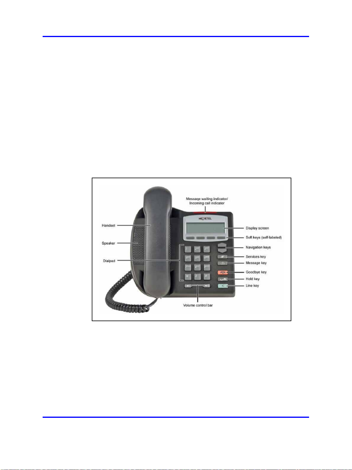
Figure 1 "IP Phone 2001" (page 30) shows the IP Phone 2001.
Figure 1
IP Phone 2001
Components and functions
This section describes the following components and functions of the IP
Phone 2001:
• “Keys and functions” (page 31)
• “Services menu” (page 31)
Nortel Communication Server 1000
NN43001-368 05.06 30 April 2010
Copyright © 2003-2010 Nortel Networks. All Rights Reserved.
IP Phones Fundamentals
Page 31

Components and functions 31
Keys and functions
Table 1 "IP Phone 2001 keys and functions" (page 31) describes the IP
Phone 2001 keys and functions.
Table 1
IP Phone 2001 keys and functions
Key Function
Speaker Press the Line key to activate the speaker for on-hook dialing and
listening.
Message waiting/
Incoming call indicator
Volume control bar
Navigation keys Use the navigation keys to scroll through menus and lists in the
Line key Use the Line key to access the single line and activate on-hook
Hold key Press the Hold key to put an active call on hold. Press the Dial/Line
Context-sensitive soft keys
(self-labeled)
Message key Press the Message key to access your voice mailbox.
Goodbye key Press the Goodbye key to terminate an active call.
The Message waiting lamp turns on to indicate that a message is left
for the user. This lamp also flashes when the IP Phone ringer is on.
Use the volume control bar to adjust the volume of the Handset,
Ringer, and On-hook Dialing/Listen tones.
Press the right side of the rocker bar to increase volume; press the
left side to decrease volume.
display area.
dialing. No status icon or light emitting diode (LED) is provided.
key to return to the caller on hold.
Context-sensitive soft keys (self-labeled) are located below the
display area. The LCD label above the key changes, based on the
active feature. A triangle before a key label indicates that the key is
active.
Services menu
Table 2 "Services menu" (page 31) shows the Services menu.
Table 2
Services menu
Services key
Press the Services key to access the following items:
• Telephone Options
— Volume adjustment
— Contrast adjustment
— Language
— Date/Time
— Local DialPad Tone
Nortel Communication Server 1000
IP Phones Fundamentals
NN43001-368 05.06 30 April 2010
Copyright © 2003-2010 Nortel Networks. All Rights Reserved.
Page 32

32 Nortel IP Phone 2001
•
•
• Test Local Mode and Resume Local Mode (if Branch Office is configured)
Press the Services key to exit from any menu or menu item.
You can customize the IP Phone features to meet user requirements. For
more information, see the IP Phone 2001 User Guide (NN43115-102).
— Set Info
— Diagnostics
— Ring type
— Call Timer
— Live Dialpad
— Normal Mode indication
— Caller ID display order
Password Admin
— Station Control Password
Virtual Office Login and Virtual Office Logout (if Virtual Office is configured)
Double-press the Services key to access Network diagnostic utilities. For
more information about Network diagnostic utilities, see “IP Phone diagnostic
utilities” (page 569).
If an incoming call is presented while you configure information in the Services menu, the phone
rings. However, the display does not update with the caller ID, and the programming text is not
disturbed.
While you are in the Services menu you cannot dial digits but you can use the programmable line
keys, such as Redial (double-press a line key) and Auto dial key to make a call. However, the
display does not update with the dialed digits or Caller ID.
Features
The IP Phone 2001 supports the following telephony features:
•
four context-sensitive soft keys
Functions for the context-sensitive soft keys are configured in LD 11.
For more information about context-sensitive soft keys, see Features
and Services Fundamentals (NN43001-106).
• volume control bar to adjust ringer, speaker, handset volume
• two specialized feature keys
— Message/Inbox
— Services
• two call-processing keys
Nortel Communication Server 1000
IP Phones Fundamentals
NN43001-368 05.06 30 April 2010
Copyright © 2003-2010 Nortel Networks. All Rights Reserved.
Page 33

— Goodbye
—
Hold
Display characteristics
An IP Phone 2001 has two display areas:
• “Information line display” (page 33)
• “Soft key label display” (page 34)
Figure 2 "IP Phone 2001 display areas" (page 33) shows these two display
areas.
Figure 2
IP Phone 2001 display areas
Display characteristics 33
Cleaning the IP Phone display screen
Gently wipe the IP Phone display screen with a soft, dry cloth.
CAUTION
Do not use any liquids or powders on the IP Phone 2001. Using
anything other than a soft, dry cloth can contaminate IP Phone
components and cause premature failure.
Information line display
An IP Phone 2001 has a one-line information display area with the
following information:
• caller number
• caller name
•
feature prompt strings
• user-entered digits
Nortel Communication Server 1000
IP Phones Fundamentals
NN43001-368 05.06 30 April 2010
Copyright © 2003-2010 Nortel Networks. All Rights Reserved.
Page 34

34 Nortel IP Phone 2001
• date and time information (if the IP Phone is in an idle state) or Call
Timer (if provisioned in the Telephone options menu)
• set information
The information area changes according to the call-processing state and
active features.
Soft key label display
The soft key label has a maximum six characters. Each soft key includes
the soft key label and an icon. When a soft key is in use, a triangle icon
appears at the beginning of the soft key label, and the label shifts one
character to the right. (If the label is six characters in length, the last or
rightmost character is truncated.) If a feature is enabled, the icon state
turns to On. The icon remains in the on state until the feature key is
pressed again. This cancels the enabled feature and turns the icon off,
and returns the soft key label to its original state.
Use the More soft key to navigate the layers of functions. If only four
functions are assigned to the soft keys, the More key does not appear,
and all four functions are displayed.
Package components
The following information applies to IP Phone 2001, IP Phone 2002, and
IP Phone 2004. Product codes for IP Phone 2001, IP Phone 2002, and IP
Phone 2004 are different from previous IP Phones.
See the product code on the back of the phone to confirm whether it is an
IP Phone 2001, IP Phone 2002, and IP Phone 2004. The product code for
IP Phone 2001, IP Phone 2002, and IP Phone 2004 appears as IP Phone
200x. The product code for previous versions of the IP Phones appears
with an i in front of the model number (for example, i200x).
You must order the global power supply separately if local power using the
global power supply is required, because IP Phone 2001, IP Phone 2002,
and IP Phone 2004 include integrated support for a number of power over
LAN options, including support for IEEE 802.3af standard power.
Table 3 "Package components" (page 35) lists the IP Phone 2001 package
components.
Nortel Communication Server 1000
IP Phones Fundamentals
NN43001-368 05.06 30 April 2010
Copyright © 2003-2010 Nortel Networks. All Rights Reserved.
Page 35

Table 3
Package components
• IP Phone 2001
• handset
• handset cord
•
2.1 m (7-ft) CAT5-e Ethernet cable
• Getting Started Card
•
number plate and lens
Table 4 "IP Phone 2001 components list" (page 35) lists the IP Phone
2001 components and product codes.
Table 4
IP Phone 2001 components list
Package components 35
Component
IP Phone 2001 (Ethergray) with Icon keycaps NTDU90AA16/A0533387
IP Phone 2001 (Ethergray) with English text label keycaps NTDU90BA16/A0533388
IP Phone 2001 (Charcoal) with Icon keycaps NTDU90AA70/A0053389
IP Phone 2001 (Charcoal) with English text label keycaps NTDU90BA70/A0533390
IP Phone 2001 (Charcoal with Bezel) with Icon keycaps NTDU90AB70
IP Phone 2001 (Charcoal with Bezel) with Icon keycaps (RoHS) NTDU90AC70E6
IP Phone 2001 (Charcoal with Bezel) with English text label keycaps NTDU90BB70
IP Phone 2001 (Charcoal with Bezel) with English text label keycaps
(RoHS)
Replacement parts
7-ft. CAT5-e N0177422
Handset, Charcoal A0758634
Handset cord, Ethergray; for IP Phone 2004 and IP Phone 2001 A088682
Handset cord, Charcoal; for IP Phone 2004 and IP Phone 2001 N0000764
Power supply
Global power supply (for local power) NTYS17xxE6
Product code
NTDU90BC70E6
IEC cables
1.8 m (5.9 ft), 10 amp, IEC320-C13
North America
2.4 m (8 ft), 240 VAC 10 amp, ANZ power cord AS-3,
Australia, New Zealand
Note: ROHS does not apply in this region.
Nortel Communication Server 1000
IP Phones Fundamentals
NN43001-368 05.06 30 April 2010
Copyright © 2003-2010 Nortel Networks. All Rights Reserved.
NTYS14AAE6
NTTK15AA
Page 36

36 Nortel IP Phone 2001
Power supply
250 VAC, Option 11C Standard European power cord,
Other EMEA, Kenya, Korea, Thailand, Indonesia, Vietnam, India,
Pakistan
3 m (9.9 ft) 125 VAC, Option 11C Swiss power cord
Switzerland
240 VAC, Option 11C UK power cord
Hong Kong, Ireland, United Kingdom, Singapore, Malaysia,
Bangladesh, Brunei, Sri Lanka
3 m (9.9 ft), 125 VAC, Option 11C Denmark power cord
Denmark
Argentina
Note: ROHS does not apply in this region.
1.8 m (5.9 ft), 10 amp, IEC320-C13
Japan
For more information, and for information about previous versions of the IP
Phone, contact your Nortel representative.
Installation and configuration
The following sections provide a step-by-step guide to install and configure
the IP Phone 2001:
• “Before you begin” (page 36)
NTTK16ABE6
NTTK17ABE6
NTTK18ABE6
NTTK22ABE6
A0814961
NTTK26AAE6
•
“First-time installation” (page 37)
•
“Configuring the IP Phone 2001” (page 37)
•
“Connecting the components” (page 38)
•
“Startup sequence” (page 39)
Before you begin
Before installing the IP Phone 2001, complete the following pre-installation
checklist:
• Ensure one IP Phone 2001 boxed package exists for each IP Phone
2001 you install. For a list of IP Phone 2001 package components, see
Table 3 "Package components" (page 35).
• Ensure one Software License exists for each IP Phone 2001 you
install.
• Ensure the host Call Server is equipped with a Signaling Server that
runs the Line Terminal Proxy Server (LTPS) application.
• If a global power supply is required, make sure you use the correct
global power supply supplied by Nortel and country specific IEC cable.
Nortel Communication Server 1000
IP Phones Fundamentals
NN43001-368 05.06 30 April 2010
Copyright © 2003-2010 Nortel Networks. All Rights Reserved.
Page 37

The voltage rating of the global power supply must match the wall
outlet voltage. See Table 4 "IP Phone 2001 components list" (page
35).
• Ensure the latest IP Phone firmware is deployed to the IP telephony
node. For more information, see Signaling Server IP Line Applications
Fundamentals (NN43001-125).
First-time installation
You must first install an IP telephony node with the Communication Server.
For information about installing an IP telephony node, see Signaling Server
IP Line Applications Fundamentals (NN43001-125).
CAUTION
Do not plug your IP Phone 2001 into an ISDN connection.
Severe damage can result.
Configuring the IP Phone 2001
Use Procedure 1 “Configuring the IP Phone 2001” (page 37) to configure
the IP Phone 2001 for the first time.
Installation and configuration 37
Procedure 1
Configuring the IP Phone 2001
Step Action
1 Configure a virtual loop on the Call Server using LD 97. For
more information about configuring a virtual loop, see Signaling
Server IP Line Applications Fundamentals (NN43001-125) and
Software Input Output Reference-Administration (NN43001-611).
2 Configure the IP Phone 2001 on the Call Server using LD 11. At
the prompt, enter the following:
REQ:new
TYPE:2001P2
For more information about configuring the IP Phone 2001 using
LD 11, see Software Input Output Reference-Administration
(NN43001-611).
3 Configure the IP Phone 2001 in Element Manager. IP Phones
are configured using the Phones section in the Element
Manager navigation tree. For more information about configuring
the IP Phone 2001 using Element Manager, see Element
Manager System Reference - Administration (NN43001-632).
--End--
Nortel Communication Server 1000
IP Phones Fundamentals
NN43001-368 05.06 30 April 2010
Copyright © 2003-2010 Nortel Networks. All Rights Reserved.
Page 38

38 Nortel IP Phone 2001
Connecting the components
Use “Connecting the components” (page 38) to connect the IP Phone
2001 components.
Procedure 2
Connecting the components
Step Action
1 Connect one end of the handset cord to the handset jack on the
2 Connect the other end of the handset cord to the handset.
3 Connect one end of the CAT5-e Ethernet cable to the network
back of the IP Phone identified with a handset icon. See Figure 3
"IP Phone 2001 Ethernet network interface connections" (page
39).
interface located on the back of the IP Phone (identified with
a LAN icon, see Figure 3 "IP Phone 2001 Ethernet network
interface connections" (page 39)). The other end of the CAT5-e
Ethernet cable plugs into the IP network.
The LAN Ethernet port supports Auto-Media Dependent Interface
Crossover (MDIX). Auto-MDIX is supported only when the
Ethernet port is configured for autonegotiation.
4 Connect the global power supply (optional). Leave the global
power supply unplugged from the power outlet, connect the
global power supply to the AC adapter jack in the bottom of
the phone. Form a small bend in the cable and then thread the
global power supply cord through the channels in the stand.
5 Secure the IP Phone footstand to the base of the IP Phone. Use
the angle adjustment grip on the top back of the IP Phone to
adjust the position.
CAUTION
Damage to Equipment
Do not plug any device into your IP Phone 2001
Ethernet port other than an IEEE 802.3 Ethernet
network connection.
Nortel Communication Server 1000
IP Phones Fundamentals
NN43001-368 05.06 30 April 2010
Copyright © 2003-2010 Nortel Networks. All Rights Reserved.
Page 39

Installation and configuration 39
Figure 3
IP Phone 2001 Ethernet network interface connections
6 Power the IP Phone 2001 using either the Power over Ethernet
or a global power supply (local power). If you are using local
power, plug the a global power supply into the nearest power
outlet. Make sure you use the correct global power supply
supplied by Nortel and country specific IEC cable. The voltage
rating of the power supply must match the wall outlet voltage.
See Table 4 "IP Phone 2001 components list" (page 35).
The IP Phone 2001 supports both AC power and Power over
LAN options, including IEEE 802.3af Power Classification 2. To
use Power over Ethernet, where power is delivered over the
CAT5-e cable, the LAN must support Power over Ethernet, and
the global power supply is not required. To use local AC power,
the optional global power supply can be ordered separately.
When you complete the IP Phone connection, you must connect the phone
to the network. See “Dynamic Host Configuration Protocol” (page 424).
Startup sequence
When an IP Phone 2001 connects to the network, it must perform a startup
sequence. The elements of the startup sequence include:
• obtaining network access (if supported by the network infrastructure)
• obtaining VLAN ID (if supported by the network infrastructure)
• obtaining the IP parameters
--End--
Nortel Communication Server 1000
IP Phones Fundamentals
NN43001-368 05.06 30 April 2010
Copyright © 2003-2010 Nortel Networks. All Rights Reserved.
Page 40

40 Nortel IP Phone 2001
• connecting to the Call Server
• obtaining the provisioning parameters
For information about provisioning the IP Phone, see “Manual provisioning
of IP Phones 2000 Series” (page 551).
Redeploying an IP Phone 2001
You can redeploy an existing previously configured IP Phone 2001 on
the same system. For example, the IP Phone 2001 can be assigned to
a new user (new TN) or to an existing user who moved to a new subnet
by changing the TN of the IP Phone 2001. For further information, see
Converging the Data Network with VoIP Fundamentals (NN43001-260).
Procedure 3
Changing the TN of an existing IP Phone 2001
Step Action
1 Repower the IP Phone 2001.
During the reboot sequence of a previously configured IP
Phone, the IP Phone 2001 displays the existing node number
for approximately five seconds.
2 If the node password is enabled and NULL, choose one of the
following:
a Disable the password.
b Set the password as non-NULL.
3 Press OK when the node number displays.
If Then
the node password is enabled
and is not NULL
the node password is disabled a TN screen displays. Go to Step
a password screen displays. Go
to Step 4.
5.
4 Enter password at the password screen, and press OK.
A TN screen displays.
To obtain the password, enter the nodePwdShow command in
Element Manager. For further information, see Element Manager
System Reference - Administration (NN43001-632).
5 Select the Clear soft key to clear the existing TN.
6 Enter the new TN.
--End--
Nortel Communication Server 1000
IP Phones Fundamentals
NN43001-368 05.06 30 April 2010
Copyright © 2003-2010 Nortel Networks. All Rights Reserved.
Page 41

Replacing an IP Phone 2001
ATTENTION
Two IP Phones cannot share the same TN. You must remove the IP Phone
2001 that currently uses the TN.
Procedure 4
Replacing an IP Phone 2001
Step Action
1 Obtain the node and TN information of the phone you want to
replace.
2 Disconnect the IP Phone 2001 that you want to replace.
3 Follow “Configuring the IP Phone 2001” (page 37) to install the
IP Phone 2001. To configure the IP Phone, “Manual provisioning
of IP Phones 2000 Series” (page 551).
4 Enter the same TN and Node Number as the IP Phone 2001 you
replaced. The system associates the new IP Phone 2001 with
the existing TN.
Removing an IP Phone 2001 from service 41
Removing an IP Phone 2001 from service
Procedure 5
Removing an IP Phone 2001 from service
Step Action
1 Disconnect the IP Phone 2001 from the network or turn off the
power.
If the IP Phone 2001 was automatically configured, the DHCP
lease expires and the IP address returns to the available pool.
2 In LD 11, enter the following:
REQ: OUT
TYPE: 2001P2
TN: LLL S CC UU
--End--
--End--
Nortel Communication Server 1000
IP Phones Fundamentals
NN43001-368 05.06 30 April 2010
Copyright © 2003-2010 Nortel Networks. All Rights Reserved.
Page 42

42 Nortel IP Phone 2001
Nortel Communication Server 1000
IP Phones Fundamentals
NN43001-368 05.06 30 April 2010
Copyright © 2003-2010 Nortel Networks. All Rights Reserved.
Page 43

.
Nortel IP Phone 2002
Contents
This section contains the following topics:
•
“Introduction” (page 43)
• “Description” (page 44)
•
“Components and functions” (page 44)
• “Features” (page 47)
•
“Display characteristics” (page 48)
• “Package components” (page 49)
•
“Installation and configuration” (page 51)
• “Redeploying an IP Phone 2002” (page 55)
•
“Replacing an IP Phone 2002” (page 56)
•
“Removing an IP Phone 2002 from service” (page 57)
43
Introduction
This section explains how to install and maintain the IP Phone 2002. For
information about using the IP Phone 2002, see the IP Phone 2002 User
Guide (NN43116-104).
This section contains the following procedures:
• Procedure 6 “Configuring the IP Phone 2002” (page 52)
• Procedure 7 “Connecting the components” (page 53)
• Procedure 8 “Changing the TN of an existing IP Phone 2002” (page
55).
• Procedure 9 “Replacing an IP Phone 2002” (page 56).
• Procedure 10 “Removing an IP Phone 2002 from service” (page 57).
Nortel Communication Server 1000
IP Phones Fundamentals
NN43001-368 05.06 30 April 2010
Copyright © 2003-2010 Nortel Networks. All Rights Reserved.
Page 44

44 Nortel IP Phone 2002
If power to the phone is interrupted after you install and configure an IP
phone, you are not required to reenter the IP Parameters, Node Numbers,
or Terminal Number (TN). There is also no need to again acquire the
firmware.
Description
The IP Phone 2002 uses the customer IP data network to communicate
with the Communication Server 1000 (CS 1000). The IP Phone 2002
translates voice into data packets for transport using Internet Protocol.
Use a Dynamic Host Configuration Protocol (DHCP) server to provide
information that you can use for the IP Phone 2002 network and CS 1000
connections.
Figure 4 "IP Phone 2002" (page 44) shows the IP Phone 2002.
Figure 4
IP Phone 2002
Components and functions
This section describes the following components and functions of the IP
Phone 2002:
• “Keys and functions” (page 45)
• “Services menu” (page 46)
Nortel Communication Server 1000
NN43001-368 05.06 30 April 2010
Copyright © 2003-2010 Nortel Networks. All Rights Reserved.
IP Phones Fundamentals
Page 45

Components and functions 45
Keys and functions
Table 5 "IP Phone 2002 keys and functions" (page 45) describes the IP
Phone 2002 keys and functions.
Table 5
IP Phone 2002 keys and functions
Key Function
Speaker Press the Line key to activate the speaker for on-hook dialing and
listening.
Programmable line
(DN)/feature keys
(self-labeled)
Programmable line (DN)/feature keys (self-labeled) are configured
for various features on the IP Phone. One must be the prime DN
key.
A steady LCD light beside a line (DN) key indicates the feature or
line is active. A flashing LCD indicates the line is on hold or the
feature is being programmed.
Message waiting light/
Incoming call indicator
The Message waiting light turns ON to indicate that a message has
been left for the user. This light also flashes when the set ringer is
ON.
Context-sensitive soft keys
(self-labeled)
Context-sensitive soft keys (self-labeled) are located below the
display area. The LCD label above the key changes, based on the
active feature.
A triangle before a key label indicates that the key is active.
Navigation keys Use the navigation keys to scroll through menus and lists in the
display area.
Message (Inbox) Press the Message (Inbox) key to access your voice mailbox.
Outbox/Shift Press the Outbox/Shift key to switch between two feature key pages
and access an additional six lines/features.
Directory Press the Directory key to access Directory services.
Quit
Press the Quit key to end an active application.
Pressing the Quit key does not affect the status of the calls currently
on your IP Phone.
Expand to PC The Expand to PC key is used to access external server
applications such as External Application Server (XAS).
Goodbye Press the Goodbye key to terminate an active call.
Hold Press the Hold key to put an active call on hold. Press the line (DN)
key beside the flashing LCD to return to the caller on hold.
Headset Press the Headset key to answer a call using the headset or to
switch a call from the handset or Handsfree to the headset.
Nortel Communication Server 1000
IP Phones Fundamentals
NN43001-368 05.06 30 April 2010
Copyright © 2003-2010 Nortel Networks. All Rights Reserved.
Page 46

46 Nortel IP Phone 2002
Table 5
IP Phone 2002 keys and functions (cont’d.)
Key Function
Mute
Volume control bar
Handsfree key
Services menu
Table 6
Services menu
Press the Mute key to listen to the receiving party without
transmitting.
Press the Mute key again to return to a two-way conversation.
The Mute key applies to Handsfree, Handset, and Headset
microphones.
The Mute LED flashes when the Mute option is in use.
Use the volume control bar to adjust the volume of the handset,
headset, speaker, ringer, and, Handsfree feature.
Press the right side of the rocker bar to increase volume; press the
left side to decrease volume.
Press the Handsfree key to activate the Handsfree feature.
The LED lights to indicate when handsfree is active.
Table 6 "Services menu" (page 46) shows the Services menu.
Services key
Press the Services key to access the following items:
• Telephone Options
— Volume Adjustment
— Contrast Adjustment
— Language
— Date/Time Format
— Display diagnostics
— Local Dialpad Tone
— Set Info
— Ring type
— OnHook Default Path
— Change Feature key label
— Call Timer
— Live Dialpad
Nortel Communication Server 1000
IP Phones Fundamentals
NN43001-368 05.06 30 April 2010
Copyright © 2003-2010 Nortel Networks. All Rights Reserved.
Page 47

Features 47
— Normal Mode indication
— Caller ID display order
•
Password Administration
•
Virtual Office Login and Virtual Office Logout (if Virtual Office is configured)
•
Test Local Mode and Resume Local Mode (if Branch Office is configured)
You can customize the IP Phone features to meet user requirements. For
more information, see the IP Phone 2002 User Guide (NN43116-104).
Double-press the Services key to access Network diagnostic utilities. For more information about
Network diagnostic utilities, see “IP Phone diagnostic utilities” (page 569).
If an incoming call is presented while you configure information in the Services menu, the phone
rings. However, the display does not update with the caller ID, and the programming text is not
disturbed.
While you are in the Services menu you cannot dial digits but you can use the programmable line
keys, such as Redial (double-press a line key) and Auto dial key to make a call. However, the
display does not update with the dialed digits or Caller ID.
Features
The IP Phone 2002 supports the following telephony features:
•
four programmable line (DN)/feature keys (self-labeled)
•
four context-sensitive soft keys (self-labeled)
Functions for the context-sensitive soft keys are configured in LD 11.
For more information about context-sensitive soft keys, see Features
and Services Fundamentals (NN43001-106).
•
volume control bar to adjust ringer, speaker, handset, handsfree, and
headset volume
•
ability to change the programmable line (DN)/feature key labels
•
six specialized feature keys
— Quit
— Directory
— Message/Inbox
— Shift/Outbox
— Services
— Expand to PC
• five call-processing fixed keys:
Nortel Communication Server 1000
IP Phones Fundamentals
NN43001-368 05.06 30 April 2010
Copyright © 2003-2010 Nortel Networks. All Rights Reserved.
Page 48

48 Nortel IP Phone 2002
— Mute
—
Handsfree
—
Goodbye
—
Headset
—
Hold
For more information about IP Phone features, see “Features” (page 389).
Display characteristics
An IP Phone 2002 has three major display areas:
•
“Programmable line (DN)/feature key label display” (page 48)
• “Information line display” (page 49)
•
“Soft key label display” (page 49)
Figure 5 "IP Phone 2002 display areas" (page 48) shows these three
display areas.
Figure 5
IP Phone 2002 display areas
Cleaning the IP Phone display screen
Gently wipe the IP Phone display screen with a soft, dry cloth.
CAUTION
Do not use any liquids or powders on the IP Phone. Using
anything other than a soft, dry cloth can contaminate IP Phone
components and cause premature failure.
Programmable line (DN)/feature key label display
The feature key label area displays a 10-character string for each of the
four feature keys. Each feature key includes the key label and an icon.
The icon state can be on, off, or flashing. A telephone icon displays the
Nortel Communication Server 1000
IP Phones Fundamentals
NN43001-368 05.06 30 April 2010
Copyright © 2003-2010 Nortel Networks. All Rights Reserved.
Page 49

status of the configured DN. Key labels are left-aligned for keys on the
left side of the screen, and right-aligned for keys on the right side of the
screen.
If a label is longer than 10 characters, the last 10 characters are displayed
and the excess characters are deleted from the beginning of the string.
Information line display
An IP Phone 2002 has a one-line information display area with the
following information:
•
caller number
• caller name
•
feature prompt strings
• user-entered digits
• date and time information (if the IP Phone is in an idle state) or Call
Timer (if provisioned in the Telephone options menu)
The information in the display area changes, according to the
call-processing state and active features.
Package components 49
Because the IP Phone 2002 only has a one-line information display area,
you are prompted to scroll through any additional lines of information.
Soft key label display
The soft key label has a maximum six characters. Each soft key includes
the soft key label and an icon. When a soft key is in use, a triangle icon
appears at the beginning of the soft key label, and the label shifts one
character to the right. (If the label is six characters in length, the last or
rightmost character is truncated.) If a feature is enabled, the icon state
turns to On. The icon remains in the on state until the feature key is
pressed again. This cancels the enabled feature and turns the icon off,
and returns the soft key label to its original state.
Use the More soft key to navigate the layers of functions. If only four
functions are assigned to the soft keys, the More key does not appear,
and all four functions are displayed.
Package components
The following information applies to IP Phone 2001, IP Phone 2002, and
IP Phone 2004. Product codes for these IP Phones are different from
previous sets.
Nortel Communication Server 1000
IP Phones Fundamentals
NN43001-368 05.06 30 April 2010
Copyright © 2003-2010 Nortel Networks. All Rights Reserved.
Page 50

50 Nortel IP Phone 2002
See the product code on the back of the phone to confirm whether it is an
IP Phone 2001, IP Phone 2002, and IP Phone 2004. The product code for
IP Phone 2001, IP Phone 2002, and IP Phone 2004 appears as IP Phone
200x. The product code for previous versions of the IP Phone appears
with an i in front of the model number (for example, i200x).
You must order the global power supply separately if local power using the
global power supply is required, because IP Phone 2001, IP Phone 2002,
and IP Phone 2004 include integrated support for a number of power over
LAN options, including support for IEEE 802.3af standard power.
Table 7 "Package components" (page 50) lists the IP Phone 2002 package
components.
Table 7
Package components
•
IP Phone 2002
•
handset
• handset cord
• 2.1 m (7-ft) CAT5-e Ethernet cable
• Getting Started Card
• number plate and lens
Table 8 "IP Phone 2002 components list" (page 50) lists the IP Phone
2002 components and product codes.
Table 8
IP Phone 2002 components list
Component
IP Phone 2002 (Ethergray) with Icon keycaps NTDU91AA16/A0533404
IP Phone 2002 (Ethergray) with English text label keycaps NTDU91BA16/A0533405
IP Phone 2002 (Charcoal) with Icon keycaps NTDU91AA70/A0533406
IP Phone 2002 (Charcoal) with English text label keycaps NTDU91BA70/A0533407
IP Phone 2002 (Charcoal with Bezel) with Icon keycaps NTDU91AB70
IP Phone 2002 (Charcoal with Bezel) with Icon keycaps (RoHS) NTDU91AC70E6
IP Phone 2002 (Charcoal with Bezel) with English text label keycaps NTDU91BB70
IP Phone 2002 (Charcoal with Bezel) with English text label keycaps
(RoHS)
Replacement parts
Product code
NTDU91BC70E6
7 ft CAT5-e Ethernet cable N0177422
Handset, Ethergray A0788874
Nortel Communication Server 1000
IP Phones Fundamentals
NN43001-368 05.06 30 April 2010
Copyright © 2003-2010 Nortel Networks. All Rights Reserved.
Page 51

Table 8
IP Phone 2002 components list (cont’d.)
Installation and configuration 51
Component
Handset, Charcoal A0758634
Handset cord, Ethergray A0897725
Handset cord, Charcoal N0000763
Footstand, Charcoal (used for Ethergray and Charcoal models) A0891619
Power supply
Global power supply (for local power) NTYS17xxE6
IEC cables
1.8 m (5.9 ft), 10 amp, IEC320-C13
North America
2.4 m (8 ft), 240 VAC 10 amp, ANZ power cord AS-3,
Australia, New Zealand
Note: ROHS does not apply in this region.
250 VAC, Option 11C Standard European power cord,
Other EMEA, Kenya, Korea, Thailand, Indonesia, Vietnam, India,
Pakistan
3 m (9.9 ft) 125 VAC, Option 11C Swiss power cord
Switzerland
240 VAC, Option 11C UK power cord
Hong Kong, Ireland, United Kingdom, Singapore, Malaysia,
Bangladesh, Brunei, Sri Lanka
Product code
NTYS14AAE6
NTTK15AA
NTTK16ABE6
NTTK17ABE6
NTTK18ABE6
3 m (9.9 ft), 125 VAC, Option 11C Denmark power cord
Denmark
Argentina
Note: ROHS does not apply in this region.
1.8 m (5.9 ft), 10 amp, IEC320-C13
Japan
For more information, and for information about previous versions of the IP
Phone, contact Nortel.
Installation and configuration
The following sections provide a step-by-step guide to install and configure
the IP Phone 2002:
• “Before you begin” (page 52)
• “First-time installation” (page 52)
• “Configuring the IP Phone 2002” (page 52)
Nortel Communication Server 1000
IP Phones Fundamentals
NN43001-368 05.06 30 April 2010
NTTK22ABE6
A0814961
NTTK26AAE6
Copyright © 2003-2010 Nortel Networks. All Rights Reserved.
Page 52

52 Nortel IP Phone 2002
• “Connecting the components” (page 53)
• “Startup sequence” (page 55)
Before you begin
Before installing the IP Phone 2002, complete the following pre-installation
checklist:
•
Ensure one IP Phone 2002 boxed package exists for each IP Phone
2002 you install. For a list of IP Phone 2002 package components, see
Table 7 "Package components" (page 50).
•
Ensure one Software License exists for each IP Phone 2002 you
install.
• Ensure the host Call Server is equipped with a Signaling Server that
runs the Line Terminal Proxy Server (LTPS) application.
•
If a global power supply is required, make sure you use the correct
global power supply supplied by Nortel and country specific IEC cable.
The voltage rating of the global power supply must match the wall
outlet voltage. See Table 8 "IP Phone 2002 components list" (page
50).
• Ensure the latest IP Phone firmware is deployed to the IP telephony
node. For more information, see Signaling Server IP Line Applications
Fundamentals (NN43001-125).
First-time installation
You must first install an IP telephony node with the Communication Server.
For information about installing an IP telephony node, see Signaling Server
IP Line Applications Fundamentals (NN43001-125).
CAUTION
Do not plug your IP Phone 2002 into an ISDN connection.
Severe damage can result.
Configuring the IP Phone 2002
Use Procedure 6 “Configuring the IP Phone 2002” (page 52) to configure
the IP Phone 2002.
Procedure 6
Configuring the IP Phone 2002
Step Action
1 Configure a virtual loop on the Call Server using LD 97.
Nortel Communication Server 1000
IP Phones Fundamentals
NN43001-368 05.06 30 April 2010
Copyright © 2003-2010 Nortel Networks. All Rights Reserved.
Page 53

Installation and configuration 53
For more information about configuring a virtual loop, see
Signaling Server IP Line Applications Fundamentals (NN430
01-125) and Software Input Output Reference-Administration
(NN43001-611).
2 Configure the IP Phone 2002 on the Call Server using LD 11. At
the prompt, enter the following:
REQ:new
TYPE:2002P1,2002P2
For more information about configuring the IP Phone 2002 using
LD 11, see Software Input Output Reference-Administration
(NN43001-611).
3 Configure the IP Phone 2002 in Element Manager. IP Phones
are configured using the Phones section in the Element
Manager navigation tree. For more information about configuring
the IP Phone 2002 using Element Manager, see Element
Manager System Reference - Administration (NN43001-632).
--End--
Connecting the components
Use Procedure 7 “Connecting the components” (page 53) to connect the
components for the IP Phone.
Procedure 7
Connecting the components
Step Action
1 Connect one end of the handset cord to the handset jack on the
back of the IP Phone (identified with a handset icon). See Figure
6 "IP Phone 2002 Ethernet network interface connections" (page
54)
2 Connect the other end of the handset cord to the handset.
3 Choose one of the following connections:
• For an IP Phone not sharing LAN access with a PC:
Connect one end of the CAT5-e Ethernet cable to the
network interface located on the back of the IP Phone
(identified with a LAN icon). The other end of the CAT5-e
Ethernet cable plugs into the IP network.
• For an IP Phone sharing LAN access with a PC:
Connect one end of the CAT5-e Ethernet cable to the
network interface located on the back of the IP Phone
(identified with a LAN icon) and the other end to the IP
network. Insert on end of a second CAT5-e Ethernet cable
into the PC network interface located on the back of the IP
Nortel Communication Server 1000
IP Phones Fundamentals
NN43001-368 05.06 30 April 2010
Copyright © 2003-2010 Nortel Networks. All Rights Reserved.
Page 54

54 Nortel IP Phone 2002
Phone (identified with a PC icon) and the other end into the
computer.
See Figure 6 "IP Phone 2002 Ethernet network interface
connections" (page 54).
The LAN Ethernet port supports Auto-Media Dependent Interface
Crossover (MDIX). Auto-MDIX is supported only when the
Ethernet port is configured for autonegotiation. The PC Port
does not support Auto-MDIX.
CAUTION
Damage to Equipment
Do not plug any device into your IP Phone 2002
Ethernet port other than an IEEE 802.3 Ethernet
network connection. The IP Phone 2002 does not
support multiple devices connected through the PC
Ethernet port.
Figure 6
IP Phone 2002 Ethernet network interface connections
4 Connect the global power supply (optional). Leave the global
power supply unplugged from the power outlet, connect the
global power supply to the AC adapter jack in the bottom of
the phone. Form a small bend in the cable and then thread the
adapter cord through the channels in the stand.
5 Secure the IP Phone footstand to the base of the IP Phone. Use
the angle adjustment grip on the top back of the IP Phone to
adjust the position.
6 Power the IP Phone 2002 using either the Power over Ethernet
or the global power supply (local power). If you are using local
power, plug the global power supply into the nearest power
outlet. Make sure you use the correct global power supply
supplied by Nortel and country specific IEC cable. The voltage
rating of the global power supply must match the wall outlet
Nortel Communication Server 1000
IP Phones Fundamentals
NN43001-368 05.06 30 April 2010
Copyright © 2003-2010 Nortel Networks. All Rights Reserved.
Page 55

voltage. See Table 8 "IP Phone 2002 components list" (page
50).
The IP Phone 2002 supports both AC power and Power over
LAN options, including IEEE 802.3af Power Classification 2. To
use Power over Ethernet, where power is delivered over the
CAT5-e cable, the LAN must support Power over Ethernet, and a
global power supply is not required. To use local AC power, the
optional global power supply can be ordered separately.
When you complete the IP Phone connection, you must connect the phone
to the network. See “Dynamic Host Configuration Protocol” (page 424).
Startup sequence
When an IP Phone 2002 connects to the network, it must perform a startup
sequence. The elements of the startup sequence include:
• obtaining network access (if supported by the network infrastructure)
•
obtaining VLAN ID (if supported by the network infrastructure)
Redeploying an IP Phone 2002 55
--End--
•
obtaining the IP parameters
•
connecting to the Call Server
•
obtaining provisioning parameters
For information about provisioning the IP Phone, see “Manual provisioning
of IP Phones 2000 Series” (page 551).
Redeploying an IP Phone 2002
You can redeploy an existing previously configured IP Phone 2002 on the
same Call Server. For example, the IP Phone 2002 can be assigned to
a new user (new TN) or to an existing user who moved to a new subnet
by changing the TN of the IP Phone 2002. For further information, see
Converging the Data Network with VoIP Fundamentals (NN43001-260).
Procedure 8
Changing the TN of an existing IP Phone 2002
Step Action
1 Repower the IP Phone 2002.
During the reboot sequence of a previously configured IP
Phone, the IP Phone 2002 displays the existing node number
for approximately 5 seconds.
2 If the node password is enabled and NULL, choose one of the
following:
Nortel Communication Server 1000
IP Phones Fundamentals
NN43001-368 05.06 30 April 2010
Copyright © 2003-2010 Nortel Networks. All Rights Reserved.
Page 56

56 Nortel IP Phone 2002
3 Press OK when the node number displays.
a Disable the password.
b Set the password as non-NULL.
If Then
the node password is enabled
and is not NULL
the node password is disabled a TN screen displays. Go to Step
4 Enter the password at the password screen and press OK.
A TN screen displays.
To obtain the password, enter the nodePwdShow command in
Element Manager. For further information, see
System Reference - Administration (NN43001-632).
5 Select the Clear soft key to clear the existing TN.
6 Enter the new TN.
Replacing an IP Phone 2002
ATTENTION
Two IP Phones cannot share the same TN. You must remove the IP Phone
2002 that currently uses the TN.
a password screen displays. Go
to Step 4.
5.
Element Manager
--End--
Procedure 9
Replacing an IP Phone 2002
Step Action
1 Obtain the node and TN information of the phone you want to
replace.
2 Disconnect the IP Phone 2002 that you want to replace.
3 Follow “Configuring the IP Phone 2002” (page 52) to install
the IP Phone 2002. To configure the IP Phone, see “Manual
provisioning of IP Phones 2000 Series” (page 551).
4 Enter the same TN and Node Number as the IP Phone 2002 you
replaced. The Call Server associates the new IP Phone 2002
with the existing TN.
--End--
Nortel Communication Server 1000
IP Phones Fundamentals
NN43001-368 05.06 30 April 2010
Copyright © 2003-2010 Nortel Networks. All Rights Reserved.
Page 57

Removing an IP Phone 2002 from service 57
Removing an IP Phone 2002 from service
Procedure 10
Removing an IP Phone 2002 from service
Step Action
1 Disconnect the IP Phone 2002 from the network or turn off the
power.
The service to the PC is disconnected as well if the PC connects
to the IP Phone 2002.
If the IP Phone 2002 was automatically configured, the DHCP
lease expires and the IP address returns to the available pool.
2 In LD 11, enter the following:
REQ: OUT
TYPE: 2002P1, 2002P2
TN: LLL S CC UU
--End--
Nortel Communication Server 1000
IP Phones Fundamentals
NN43001-368 05.06 30 April 2010
Copyright © 2003-2010 Nortel Networks. All Rights Reserved.
Page 58

58 Nortel IP Phone 2002
Nortel Communication Server 1000
IP Phones Fundamentals
NN43001-368 05.06 30 April 2010
Copyright © 2003-2010 Nortel Networks. All Rights Reserved.
Page 59

.
Nortel IP Phone 2004
Contents
This section contains the following topics:
•
“Introduction” (page 59)
• “Description” (page 60)
•
“Components and functions” (page 60)
• “Features” (page 63)
•
“Package components” (page 66)
• “Installation and configuration” (page 68)
•
“Redeploying an IP Phone 2004” (page 72)
• “Replacing an IP Phone 2004” (page 73)
•
“Removing an IP Phone 2004 from service” (page 74)
59
Introduction
This section explains how to install and maintain the IP Phone 2004. For
information about using the IP Phone 2004, see the IP Phone 2004 User
Guide (NN43117-102).
This section contains the following procedures:
• Procedure 11 “Configuring the IP Phone 2004” (page 69)
• Procedure 12 “Connecting the components” (page 70)
• Procedure 13 “Changing the TN of an existing IP Phone 2004” (page
72).
• Procedure 14 “Replacing an IP Phone 2004” (page 73).
• Procedure 15 “Removing an IP Phone 2004 from service” (page 74).
Nortel Communication Server 1000
IP Phones Fundamentals
NN43001-368 05.06 30 April 2010
Copyright © 2003-2010 Nortel Networks. All Rights Reserved.
Page 60

60 Nortel IP Phone 2004
If power to the phone is interrupted after you install and configure an IP
phone, you are not required to reenter the IP Parameters, Node Numbers,
or Terminal Number (TN). There is also no need to again acquire the
firmware.
Description
The IP Phone 2004 uses the customer IP data network to communicate
with the Communication Server 1000 (CS 1000). The IP Phone 2004
translates voice into data packets for transport using Internet Protocol.
Use a Dynamic Host Configuration Protocol (DHCP) server to provide
information that you can use for the IP Phone 2004 network and CS 1000
connections.
Figure 7 "IP Phone 2004" (page 60) shows the IP Phone 2004.
Figure 7
IP Phone 2004
Components and functions
This section describes the following components and functions of the IP
Phone 2004:
• “Keys and functions” (page 61)
• “Services menu” (page 62)
Nortel Communication Server 1000
NN43001-368 05.06 30 April 2010
Copyright © 2003-2010 Nortel Networks. All Rights Reserved.
IP Phones Fundamentals
Page 61

Components and functions 61
Keys and functions
Table 9 "IP Phone 2004 keys and functions" (page 61) shows the IP
Phone 2004 keys and functions.
Table 9
IP Phone 2004 keys and functions
Key Function
Hold Press the Hold key to put an active call on hold. Press the line (DN) key
beside the flashing LCD to return to the caller on hold.
Goodbye Press the Goodbye key to terminate an active call.
Message waiting light/
Incoming call indicator
The Message waiting indicator turns ON to indicate that a message has
been left for the user. This indicator also flashes when the set ringer is
ON.
Programmable line
(DN)/feature keys
Programmable line (DN)/feature keys (self-labeled) are configured for
various features on the IP Phones.
(self-labeled)
A steady LCD light beside a line (DN) key indicates the feature or line is
active. A flashing LCD indicates the line is on hold or the feature is being
programmed.
Context-sensitive soft
keys (self-labeled)
Context-sensitive soft keys (self-labeled) are located below the display
area. The LCD label above the key changes, based on the active feature.
A triangle before a key label indicates that the key is active.
Fixed feature keys Use these keys to access non-programmable standard features.
Expand to PC The Expand to PC key is used to access external server applications
such as External Application Server.
Copy A fixed key reserved for future feature development. An audible
non-working tone is generated along with a display message.
Navigation keys Use the navigation keys to scroll through menus and lists in the display
area.
Outbox/Shift Press the Outbox/Shift key to switch between two feature key pages and
access an additional six lines/features.
Message (Inbox) Press the Message (Inbox) key to access your voice mailbox.
Quit
Press the Quit key to end an active application.
Pressing the Quit key does not affect the status of the calls currently on
your IP Phone.
Directory Press the Directory key to access Directory services.
Nortel Communication Server 1000
IP Phones Fundamentals
NN43001-368 05.06 30 April 2010
Copyright © 2003-2010 Nortel Networks. All Rights Reserved.
Page 62

62 Nortel IP Phone 2004
Table 9
IP Phone 2004 keys and functions (cont’d.)
Key Function
Mute
Headset Press the Headset key to answer a call using the headset or to switch a
Volume control bar
Handsfree key
Press the Mute key to listen to the receiving party without transmitting.
Press the Mute key again to return to a two-way conversation.
The Mute key applies to Handsfree, Handset, and Headset microphones.
The Mute LED flashes when the Mute option is in use.
call from the handset or Handsfree to the headset.
Use the Volume control bar to adjust the volume of the handset, headset,
speaker, ringer, and Handsfree feature.
Press the right side of the rocker bar to increase volume, the left side to
decrease volume.
Press the Handsfree key to activate handsfree.
The LED lights to indicate when the handsfree feature is active.
Services menu
Table 10 "Services menu" (page 62) shows the Services menu.
Table 10
Services menu
Services key
Press the Services key to access the following items:
• Telephone Options
— Volume Adjustment
— Contrast Adjustment
— Language
— Date/Time Format
— Display diagnostics
— Local Dialpad Tone
— Ring type
— Call Timer
— OnHook Default Path
— Change Feature Key Label
Nortel Communication Server 1000
IP Phones Fundamentals
NN43001-368 05.06 30 April 2010
Copyright © 2003-2010 Nortel Networks. All Rights Reserved.
Page 63

Features 63
— Set Info
— Live Dialpad
•
Password Administration
•
Virtual Office Login and Virtual Office Logout (if Virtual Office is configured)
•
Test Local Mode and Resume Local Mode (if Branch Office is configured)
You can customize the IP Phone features to meet user requirements. For
more information, see the IP Phone 2004 User Guide (NN43117-102).
Double-press the Services key to access Network diagnostic utilities. For more information about
Network diagnostic utilities, see “IP Phone diagnostic utilities” (page 569).
If an incoming call is presented while you configure information in the Services menu, the phone
rings. However, the display does not update with the caller ID, and the programming text is not
disturbed.
While you are in the Services menu you cannot dial digits but you can use the programmable line
keys, such as Redial (double-press a line key) and Auto dial key to make a call. However, the
display does not update with the dialed digits or Caller ID.
During an incoming call, if the selected feature page does not contain the flashing DN line key, the
display reverts to the active feature key page. This enables the user to answer the call without
pressing the Shift key.
Features
The IP Phone 2004 supports the following telephony features:
•
six programmable line (DN)/feature keys (self-labeled)
•
four context-sensitive soft keys (self-labeled)
Functions for the context-sensitive soft keys are configured in LD 11.
For more information about context-sensitive soft keys, see Features
and Services Fundamentals (NN43001-106).
•
volume control bar to adjust ringer, speaker, handset, handsfree, and
headset volume
• ability to change the programmable line (DN)/feature key labels
• seven specialized feature keys
— Quit
— Directory
— Message/Inbox
— Shift/Outbox
— Services
Nortel Communication Server 1000
IP Phones Fundamentals
NN43001-368 05.06 30 April 2010
Copyright © 2003-2010 Nortel Networks. All Rights Reserved.
Page 64

64 Nortel IP Phone 2004
— Copy
—
Expand to PC
•
five call-processing fixed keys
— Mute
— Handsfree
— Goodbye
— Headset
— Hold
For more information about IP Phone features, see “Features” (page 389).
Central Answering Position
The Central Answering Position (CAP) operates as an Automatic
Call Distribution (ACD) agent on the IP Phone 2004. A CAP provides
call-handling features, such as transferring a call, parking a call, and
answering a call. You can add an IP Phone Key Expansion Module (KEM)
to provide additional lines and features, Direct Station Select, and Busy
Lamp Field functionality.
For further information about Central Answering Position, see Central
Answering Position Implementation Guide (NN43011-501).
Display characteristics
An IP Phone 2004 has three major display areas:
•
“Programmable line (DN)/feature key label display” (page 65)
•
“Information line display” (page 65)
•
“Soft key label display” (page 66)
Figure 8 "IP Phone 2004 display areas" (page 65) shows display areas.
Nortel Communication Server 1000
IP Phones Fundamentals
NN43001-368 05.06 30 April 2010
Copyright © 2003-2010 Nortel Networks. All Rights Reserved.
Page 65

Figure 8
IP Phone 2004 display areas
Cleaning the IP Phone display screen
Gently wipe the IP Phone display screen with a soft, dry cloth.
Display characteristics 65
CAUTION
Do not use any liquids or powders on the IP Phone. Using
anything other than a soft, dry cloth can contaminate IP Phone
components and cause premature failure.
Programmable line (DN)/feature key label display
The feature key label area displays a 10-character string for each of the six
feature keys. Each feature key includes the key label and an icon. The
icon state can be on, off, or flashing. A telephone icon displays the status
of the configured DN. Key labels are left-aligned for keys on the left side of
the screen, and right-aligned for keys on the right side of the screen.
If a label is longer than 10 characters, the last 10 characters are displayed,
and the excess characters are deleted from the beginning of the string.
Information line display
An IP Phone 2004 has a three-line information display area with the
following information:
• caller number
• caller name
• feature prompt strings
Nortel Communication Server 1000
IP Phones Fundamentals
NN43001-368 05.06 30 April 2010
Copyright © 2003-2010 Nortel Networks. All Rights Reserved.
Page 66

66 Nortel IP Phone 2004
• user-entered digits
• date and time information (if the IP Phone is in an idle state) or Call
Timer (if provisioned in the Telephone options menu)
The information in the display area changes, according to the
call-processing state and active features.
Soft key label display
The soft key label has a maximum six characters. Each soft key includes
the soft key label and an icon. When a soft key is in use, a triangle icon
appears at the beginning of the soft key label, and the label shifts one
character to the right. (If the label is seven characters in length, the last or
rightmost character is truncated.) If a feature is enabled, the icon state
turns to On. The icon remains in the on state until the feature key is
pressed again. This cancels the enabled feature and turns the icon off,
and returns the soft key label to its original state.
Use the More soft key to navigate the layers of functions. If there are only
four functions assigned to the soft keys, the More key does not appear,
and all four functions are displayed.
Package components
The following information applies to IP Phone 2001, IP Phone 2002, and
IP Phone 2004. Product codes for these IP Phones are different from
previous sets.
See the product code on the back of the phone to confirm whether it is a
IP Phone 2001, IP Phone 2002, or IP Phone 2004. The product code for
IP Phone 2001, IP Phone 2002, and IP Phone 2004 appears as IP Phone
200x. The product code for previous versions of the IP Phone appears
with an i in front of the model number (for example, i200x).
You must order the global power supply separately if local power using the
global power supply is required, because IP Phone 2001, IP Phone 2002,
and IP Phone 2004 include integrated support for a number of power over
LAN options, including support for IEEE 802.3af standard power.
Table 11 "Package components" (page 67) lists the IP Phone 2004
package components.
Nortel Communication Server 1000
IP Phones Fundamentals
NN43001-368 05.06 30 April 2010
Copyright © 2003-2010 Nortel Networks. All Rights Reserved.
Page 67

Table 11
Package components
• IP Phone 2004
• handset
• handset cord
•
2.1 m (7-ft) CAT5-e Ethernet cable
• Getting Started Card
•
number plate and lens
Table 12 "IP Phone 2004 component list" (page 67) lists the IP Phone
2004 components and product codes.
Table 12
IP Phone 2004 component list
Package components 67
Component
IP Phone 2004 (Ethergray) with Icon keycaps NTDU92AA16/A0533408
IP Phone 2004 (Ethergray) with English text label
keycaps
IP Phone 2004 (Charcoal) with Icon keycaps NTDU92AA70/A0533410
IP Phone 2004 (Charcoal) with English text label
keycaps
IP Phone 2004 (Charcoal with Bezel) with Icon keycaps NTDU92AB70
IP Phone 2004 (Charcoal with Bezel) with Icon keycaps
(RoHS)
IP Phone 2004 (Charcoal with Bezel) with English text
label keycaps
IP Phone 2004 (Charcoal with Bezel) with English text
label keycaps (RoHS)
IP Phone 2004 wall mount kit (Charcoal), used with
Ethergray and Charcoal models
Replacement parts
7 ft Ethernet CAT5-e cable N0177422
Handset (Ethergray) A0788874
Product code
NTDU92BA16/A0533409
NTDU92BA70/A0533411
NTDU92AC70E6
NTDU92BB70
NTDU92BC70E6
NTMN15BA70/A0503076
Handset (Charcoal) A0758634
Handset cord (Ethergray) A0788682
Handset cord (Charcoal) N0000764
Footstand (Charcoal), used for Ethergray and Charcoal
models
Nortel Communication Server 1000
IP Phones Fundamentals
NN43001-368 05.06 30 April 2010
Copyright © 2003-2010 Nortel Networks. All Rights Reserved.
A0538587
Page 68

68 Nortel IP Phone 2004
Power supply
Global power supply (for local power) NTYS17xxE6
IEC cables
1.8 m (5.9 ft), 10 amp, IEC320-C13
North America
2.4 m (8 ft), 240 VAC 10 amp, ANZ power cord AS-3,
Australia, New Zealand
Note: ROHS does not apply in this region.
250 VAC, Option 11C Standard European power cord,
Other EMEA, Kenya, Korea, Thailand, Indonesia,
Vietnam, India, Pakistan
3 m (9.9 ft) 125 VAC, Option 11C Swiss power cord
Switzerland
240 VAC, Option 11C UK power cord
Hong Kong, Ireland, United Kingdom, Singapore,
Malaysia, Bangladesh, Brunei, Sri Lanka
3 m (9.9 ft), 125 VAC, Option 11C Denmark power cord
Denmark
Argentina
Note: ROHS does not apply in this region.
1.8 m (5.9 ft), 10 amp, IEC320-C13
Japan
For more information, and for information about previous versions of the IP
Phone, contact your Nortel representative.
NTYS14AAE6
NTTK15AA
NTTK16ABE6
NTTK17ABE6
NTTK18ABE6
NTTK22ABE6
A0814961
NTTK26AAE6
Installation and configuration
The following sections provide a step-by-step guide to install and configure
the IP Phone 2004:
• “Before you begin” (page 69)
•
“First-time installation” (page 69)
•
“Configuring the IP Phone 2004” (page 69)
• “Connecting the components” (page 70)
• “Startup sequence” (page 72)
Nortel Communication Server 1000
IP Phones Fundamentals
NN43001-368 05.06 30 April 2010
Copyright © 2003-2010 Nortel Networks. All Rights Reserved.
Page 69

Before you begin
Before installing the IP Phone 2004, complete the following pre-installation
checklist:
• Ensure one IP Phone 2004 boxed package exists for each IP Phone
2004 you install. For a list of IP Phone 2004 package components, see
Table 11 "Package components" (page 67).
•
Ensure one Software License exists for each IP Phone 2004 you
install.
• Ensure the host Call Server is equipped with a Signaling Server that
runs the Line TPS application.
•
If a global power supply is required, ensure you use the correct global
power supply supplied by Nortel and country specific IEC cable. The
voltage rating of the global power supply must match the wall outlet
voltage. See Table 12 "IP Phone 2004 component list" (page 67).
•
Ensure the latest IP Phone firmware is deployed to the IP telephony
node. For more information, see Signaling Server IP Line Applications
Fundamentals (NN43001-125).
Installation and configuration 69
First-time installation
You must first install an IP telephony node with the Communication Server.
For information about installing an IP telephony node, see Signaling Server
IP Line Applications Fundamentals (NN43001-125).
CAUTION
Do not plug your IP Phone 2004 into an ISDN connection.
Severe damage can result.
Configuring the IP Phone 2004
Use Procedure 11 “Configuring the IP Phone 2004” (page 69) to configure
the IP Phone 2004 for the first time.
Procedure 11
Configuring the IP Phone 2004
Step Action
1 Configure a virtual loop on the Call Server using LD 97.
For more information about configuring a virtual loop, see
Signaling Server IP Line Applications Fundamentals (NN430
01-125) and Software Input Output Reference-Administration
(NN43001-611).
Nortel Communication Server 1000
IP Phones Fundamentals
NN43001-368 05.06 30 April 2010
Copyright © 2003-2010 Nortel Networks. All Rights Reserved.
Page 70

70 Nortel IP Phone 2004
2 Configure the IP Phone 2004 on the Call Server using LD 11. At
3 Configure the IP Phone 2004 in Element Manager. IP Phones
Connecting the components
Use Procedure 12 “Connecting the components” (page 70) to connect the
components for the IP Phone.
the prompt, enter the following:
REQ:new
TYPE:2004P1,2004P2
For more information about configuring the IP Phone 2004 using
LD 11, see Software Input Output Reference-Administration
(NN43001-611).
are configured using the Phones section in the Element
Manager navigation tree. For more information about configuring
the IP Phone 2004 using Element Manager, see Element
Manager System Reference - Administration (NN43001-632).
--End--
Procedure 12
Connecting the components
Step Action
1 Connect one end of the handset cord to the handset jack on the
back of the IP Phone (identified with a handset icon). See Figure
9 "IP Phone 2004 Ethernet network connections" (page 71).
2 Connect the other end of the handset cord to the handset.
3 Choose one of the following connections:
• For an IP Phone not sharing a LAN access with a PC:
Connect one end of the CAT5-e Ethernet cable to the LAN
Ethernet port located on the back of the IP Phone 2004
(identified with a LAN icon). The other end of the CAT5-e
Ethernet cable plugs into the IP network.
• For an IP Phone sharing a LAN access with a PC:
Connect one end of the CAT5-e Ethernet cable to the LAN
Ethernet port located on the back of the IP Phone (identified
with a LAN icon) and the other end to the IP network. Insert
one end of a second CAT5-e Ethernet cable into the PC
Ethernet port located on the back of the IP Phone (identified
with a PC icon) and the other end into the computer.
See Figure 9 "IP Phone 2004 Ethernet network connections"
(page 71).
The LAN Ethernet port supports Auto-Media Dependent Interface
Crossover (MDIX). Auto-MDIX is supported only when the
Nortel Communication Server 1000
IP Phones Fundamentals
NN43001-368 05.06 30 April 2010
Copyright © 2003-2010 Nortel Networks. All Rights Reserved.
Page 71

Installation and configuration 71
Ethernet port is configured for autonegotiation. The PC Port
does not support Auto-MDIX.
CAUTION
Damage to Equipment
Do not plug any device into your IP Phone 2004
Ethernet port other than an IEEE 802.3 Ethernet
network connection. The IP Phone 2004 does not
support multiple devices connected through the PC
Ethernet port.
Figure 9
IP Phone 2004 Ethernet network connections
4 Connect the global power supply (optional). Leave the global
power supply unplugged from the power outlet, connect the
global power supply to the AC adapter jack in the bottom of
the phone. Form a small bend in the cable and then thread the
global power supply cord through the channels in the stand.
5 Secure the IP Phone footstand to the base of the IP Phone. Use
the angle adjustment grip on the top back of the IP Phone to
adjust the position.
6 Power the IP Phone 2004 using either the Power over Ethernet
or the global power supply (local power). If you are using local
power, plug the global power supply into the nearest power
outlet. Make sure you use the correct global power supply
supplied by Nortel and country specific IEC cable. The voltage
rating of the global power supply must match the wall outlet
Nortel Communication Server 1000
IP Phones Fundamentals
NN43001-368 05.06 30 April 2010
Copyright © 2003-2010 Nortel Networks. All Rights Reserved.
Page 72

72 Nortel IP Phone 2004
When you complete the IP Phone connection, you must connect the phone
to the network. See “Dynamic Host Configuration Protocol” (page 424).
Startup sequence
When an IP Phone 2004 connects to the network, it must perform a startup
sequence. The elements of the startup sequence include:
• obtaining network access (if supported by the network infrastructure)
•
obtaining VLAN ID (if supported by the network infrastructure)
voltage. See Table 12 "IP Phone 2004 component list" (page
67).
The IP Phone 2004 supports both AC power and Power over
LAN options, including IEEE 802.3af Power Classification 2. To
use Power over Ethernet, where power is delivered over the
CAT5-e cable, the LAN must support Power over Ethernet, and a
global power supply is not required. To use local AC power, the
optional global power supply can be ordered separately.
--End--
•
obtaining the IP parameters
•
connecting to the Call Server
•
obtaining the provisioning parameters
For information about provisioning the IP Phone, see “Manual provisioning
of IP Phones 2000 Series” (page 551).
Redeploying an IP Phone 2004
You can redeploy an existing previously configured IP Phone 2004 on the
same Call Server. For example, the IP Phone 2004 can be assigned to
a new user (new TN) or to an existing user who moved to a new subnet
by changing the TN of the IP Phone 2004. For further information, see
Converging the Data Network with VoIP Fundamentals (NN43001-260).
Procedure 13
Changing the TN of an existing IP Phone 2004
Step Action
1 Repower the IP Phone 2004.
During the reboot sequence of a previously configured IP
Phone, the IP Phone 2004 displays the existing node number
for approximately five seconds.
2 If the node password is enabled and NULL, choose one of the
following:
Nortel Communication Server 1000
IP Phones Fundamentals
NN43001-368 05.06 30 April 2010
Copyright © 2003-2010 Nortel Networks. All Rights Reserved.
Page 73

Replacing an IP Phone 2004 73
a Disable the password.
b Set the password as non-NULL.
3 Press OK when the node number displays.
If Then
the node password is enabled
and is not NULL
the node password is disabled a TN screen displays. Go to Step
4 Enter the password at the password screen, and press OK.
A TN screen displays.
To obtain the password, enter the nodePwdShow command in
Element Manager. For further information, see
System Reference - Administration (NN43001-632).
5 Select the Clear soft key to clear the existing TN.
6 Enter the new TN.
Replacing an IP Phone 2004
ATTENTION
Two IP Phones cannot share the same TN. You must remove the IP Phone
2004 that currently uses the TN.
a password screen displays. Go
to Step 4.
5.
Element Manager
--End--
Procedure 14
Replacing an IP Phone 2004
Step Action
1 Obtain the node and TN information of the phone you want to
replace.
2 Disconnect the IP Phone 2004 that you want to replace.
3 Follow “Configuring the IP Phone 2004” (page 69) to install
the IP Phone 2004. To configure the IP Phone, see “Manual
provisioning of IP Phones 2000 Series” (page 551).
4 Enter the same TN and Node Number as the IP Phone 2004 you
replaced. The Call Server associates the new IP Phone 2004
with the existing TN.
--End--
Nortel Communication Server 1000
IP Phones Fundamentals
NN43001-368 05.06 30 April 2010
Copyright © 2003-2010 Nortel Networks. All Rights Reserved.
Page 74

74 Nortel IP Phone 2004
Removing an IP Phone 2004 from service
Procedure 15
Removing an IP Phone 2004 from service
Step Action
1 Disconnect the IP Phone 2004 from the network or turn the
power off.
The service to the PC is disconnected as well if the PC connects
to the IP Phone 2004.
If the IP Phone 2004 was automatically configured, the DHCP
lease expires and the IP address returns to the available pool.
2 In LD 11, enter the following:
REQ: OUT
TYPE: 2004P1, 2004P2
TN: LLL S CC UU
--End--
Nortel Communication Server 1000
IP Phones Fundamentals
NN43001-368 05.06 30 April 2010
Copyright © 2003-2010 Nortel Networks. All Rights Reserved.
Page 75

.
75
IP Phone Key Expansion Module (KEM)
Contents
This section contains the following topics
•
“Description” (page 75)
• “Features” (page 76)
•
“Display characteristics” (page 76)
• “Key number assignments” (page 77)
•
“Package components” (page 77)
• “Configuration” (page 77)
•
“Installation” (page 80)
• “IP Phone KEM startup initialization” (page 81)
•
“Operating parameters” (page 82)
Description
The Nortel IP Phone Key Expansion Module (KEM) is a hardware
component that connects to IP Phone 2002 and IP Phone 2004 and
provides additional line appearances and feature keys (see Figure 10 "IP
Phone 2002 with one IP Phone KEM attached" (page 76)).
Up to two IP Phone KEMs can be connected to an IP Phone 2002 or IP
Phone 2004. With two IP Phone KEMs connected, the IP Phone can have
up to 48 additional line/feature keys.
The IP Phone 2004 can also have up to 48 additional line/feature keys
using the Shift key functionality and one IP Phone KEM. With two IP
Phone KEMs connected, the Shift key functionality does not affect the IP
Phone KEMs since the maximum number of line/feature keys is already
available. The IP Phone 2002 does not support Shift key functionality.
Nortel Communication Server 1000
IP Phones Fundamentals
NN43001-368 05.06 30 April 2010
Copyright © 2003-2010 Nortel Networks. All Rights Reserved.
Page 76

76 IP Phone Key Expansion Module (KEM)
Figure 10
IP Phone 2002 with one IP Phone KEM attached
Features
The IP Phone KEM has the following features:
• 12 keys on each side of an LCD provide up to 24 additional
self-labeled line/feature keys. Using the Shift key functionality, an IP
Phone 2004 can have up to 48 additional logical line/feature keys.
• A desk-mount bracket and structural baseplate connect the IP Phone
KEM to an IP Phone 2002 or IP Phone 2004, or to another IP Phone
KEM.
• A wall-mount bracket installs the IP Phone KEM alongside a
wall-mounted IP Phone 2002 or IP Phone 2004.
Display characteristics
The IP Phone KEM has one LCD between the two rows of 12 Line/feature
keys (see Figure 10 "IP Phone 2002 with one IP Phone KEM attached"
(page 76)). Each of the 24 physical keys on the IP Phone KEM has a
10-character display label. This label is set automatically, however, the
user can edit the label using the controls on the IP Phone.
Nortel Communication Server 1000
IP Phones Fundamentals
NN43001-368 05.06 30 April 2010
Copyright © 2003-2010 Nortel Networks. All Rights Reserved.
Page 77

To alter the display and contrast on the IP Phone KEM, use the Contrast
Adjustment option under the Telephone Options menu on the IP Phone.
Any contrast changes you make on the IP Phone affect the IP Phone
KEM. The IP Phone KEM and IP Phone do not have separate contrast
adjustments.
Key number assignments
Since the IP Phone 2002 and IP Phone 2004 have key number
assignments from 0 to 31, the IP Phone KEM key number assignments
begin at 32. Therefore, the first IP Phone KEM has key number
assignments from 32 to 55, and the second IP Phone KEM has key
number assignments from 56 to 79.
For more information about key number assignments, see “IP Phone
context-sensitive soft keys” (page 679).
Package components
Table 13 "IP Phone KEM components list" (page 77) lists the IP Phone
KEM package components.
Configuration 77
Table 13
IP Phone KEM components list
Components Order code
IP Phone KEM - Ethergray A0540989
IP Phone KEM - Charcoal A0540990
IP Phone KEM wall mount kit - Charcoal A0555218
Configuration
The IP Phone KEM must be configured in LD 11 before it is used.
Table 14
LD 11: Configure the IP Phone KEM
Prompt Response Description
REQ: NEW CHG Add new data. Change existing data.
TYPE:
... ...
ZONE
2002P2
2004P2
0 – 255
IP Phone 2002
IP Phone 2004
Zone number to which the IP Phone 2002 or IP Phone
2004 belongs
Nortel Communication Server 1000
IP Phones Fundamentals
NN43001-368 05.06 30 April 2010
Copyright © 2003-2010 Nortel Networks. All Rights Reserved.
Page 78

78 IP Phone Key Expansion Module (KEM)
Table 14
LD 11: Configure the IP Phone KEM (cont’d.)
Prompt Response Description
KEM (0) – 2
....
KEY
xx aaa yyyy
(cccc or D) zz..z
Number of attached IP Phone KEMs
Up to two IP Phone KEMs can be attached to an IP
Phone. Pressing <CR> without entering a number leaves
the value unchanged.
Telephone function key assignments
The following key assignments determine calling options
and features available to an IP Phone. Note that KEY is
prompted until a carriage return <CR> is entered.
Where:
xx = key number
aaa = key name or function
yyy = additional information required for the key
zz.z = additional information required for the key aaa.
The cccc or D entry deals specifically with the Calling Line
Identification feature, where:
cccc = CLID table entry of (0)-N, where N = the value
entered at the SIZE prompt in LD 15 minus 1.
D = the character "D". When the character "D" is entered,
the system searches the DN keys from key 0 and up,
to find a DN key with a CLID table entry. The CLID
associated with the found DN key is then used.
The position of the (cccc or D) field varies depending on
the key name or function.
You may enter a CLID table entry if aaa = ACD, HOT d,
HOT L, MCN, MCR, PVN, PVR, SCN, or SCR.
Type xx NUL to remove a key function or feature.
Nortel Communication Server 1000
IP Phones Fundamentals
NN43001-368 05.06 30 April 2010
Copyright © 2003-2010 Nortel Networks. All Rights Reserved.
Page 79

Table 14
LD 11: Configure the IP Phone KEM (cont’d.)
Prompt Response Description
Configuration 79
PAGEOFST <Page>
<KeyOffset>
KEY xx
Automatically calculates the IP Phone KEM key based
on the entered values. This prompt enables the system
administrator to enter a Page number of 0 or 1 and a
Key Offset number from 0 to 23. Once entered, the KEY
prompt is prompted with the appropriate KEY value filled
in.
Enter <CR> to terminate data entry.
Applies to an IP Phone 2004 with
KEM = 1, and where <CR> was entered at the KEY
prompt.
Does not apply to an IP Phone 2002.
When values are entered for Page and KeyOffset, the
KEY xx prompt displays, followed by PAGEOFST prompt.
This loop continues until no values (<CR> only) are
entered at the PAGEOFST prompt.
Edit the IP Phone KEM key number specified by
PAGEOFST, where:
xx = the number of the key (for example, KEY 36)
Enter <CR> to keep the current setting.
KEMOFST <KEM>
<KeyOffset>
Automatically calculates the IP Phone KEM key based
on the entered values. This prompt enables the system
administrator to enter a KEM number of 1 or 2 and a Key
Offset number from 0-23. Once entered, the KEY prompt
is prompted with the appropriate KEY value filled in.
Enter <CR> to terminate data entry.
When values are entered for KEM and KeyOffset, the KEY
xx prompt displays, followed by KEMOFST prompt. This
loop continues until no values (<CR> only) are entered at
the KEMOFST prompt.
Applies to an IP Phone 2002 if <CR> was entered at the
KEY prompt.
Nortel Communication Server 1000
IP Phones Fundamentals
NN43001-368 05.06 30 April 2010
Copyright © 2003-2010 Nortel Networks. All Rights Reserved.
Page 80

80 IP Phone Key Expansion Module (KEM)
Table 14
LD 11: Configure the IP Phone KEM (cont’d.)
Prompt Response Description
Applies to an IP Phone 2004 with
KEM = 2, and where <CR> was entered at the KEY
prompt.
KEY xx
Edit the IP Phone KEM key number specified by
KEMOFST, where:
xx = the number of the key (for example, KEY 36)
Enter <CR> to keep the current setting.
Installation
The IP Phone KEM mounts on the right side of an IP Phone 2002 or IP
Phone 2004. The IP Phone KEM snaps into the receptacle on the back
of the IP Phone using the desk-mount bracket and structural baseplate
supplied with the IP Phone KEM (see Figure 11 "IP Phone KEM attached
to an IP Phone 2002" (page 80)).
The IP Phone KEM connects to the IP Phone 2002 or IP Phone 2004
using the Accessory Expansion Module (AEM) port on the IP Phone.
Figure 11
IP Phone KEM attached to an IP Phone 2002
Nortel Communication Server 1000
IP Phones Fundamentals
NN43001-368 05.06 30 April 2010
Copyright © 2003-2010 Nortel Networks. All Rights Reserved.
Page 81

IP Phone KEM startup initialization 81
Procedure 16
Connecting the IP Phone KEM to an IP Phone 2002 or IP Phone 2004
Step Action
1 Remove the IP Phone from the stand by pressing the IP Phone
tilt handle, and pulling the IP Phone away from the stand.
For the IP Phone 2004, you can also adjust the stand angle to
maximum, instead of removing the stand.
2 Place the connecting arm of the IP Phone KEM behind the IP
Phone and align the IP Phone KEM connection plug to the AEM
port on the back of the IP Phone.
The IP Phones 2002 with the product codes: NTDU76AB34,
NTDU76BB34, NTDU76AB70, and NTDU76BB70 have shorter
connector pins than the other IP Phone 2002. Therefore, the
ribbon cable connector of the IP Phone KEM must be detached
from the retaining clip and pressed manually into the header
connector before attaching the IP Phone KEM.
3 Press the IP Phone KEM and IP Phone firmly together until the
IP Phone KEM locks into place.
4 If connecting a second IP Phone KEM, repeat steps 1 to 3.
The second IP Phone KEM is attached to the right side of the
first IP Phone KEM.
5 Attach the IP Phone stand and the IP Phone KEM stand, if
removed. Adjust each IP Phone KEM stand to the same angle
as the IP Phone.
The IP Phone KEM powers up.
The IP Phone KEM uses the electrical connection of the IP
Phone 2002 or IP Phone 2004 for power. It does not have its
own power source.
IP Phone KEM startup initialization
Once the IP Phone KEM has been installed and powered up on your IP
Phone 2002 or IP Phone 2004, the IP Phone KEM initializes (see Table 15
"Startup initialization process for the IP Phone KEM" (page 82)).
--End--
Nortel Communication Server 1000
IP Phones Fundamentals
NN43001-368 05.06 30 April 2010
Copyright © 2003-2010 Nortel Networks. All Rights Reserved.
Page 82

82 IP Phone Key Expansion Module (KEM)
Table 15
Startup initialization process for the IP Phone KEM
Phase Description
1. IP Phone KEM performs
self-test
2. IP Phone KEM
establishes communication
with the IP Phone
3. IP Phone KEM
downloads keymaps
When the three phases complete successfully, you are ready to use the
additional line/feature keys on your IP Phone KEM.
If you have a second IP Phone KEM installed on your IP Phone, the one to
the immediate right of the IP Phone must be functional for the subsequent
IP Phone KEM to work. This is because the second IP Phone KEM
receives its power, and communicates with the IP Phone, through the first
IP Phone KEM.
The self-test confirms the operation of the IP Phone KEM local
memory, CPU, and other circuitry. While undergoing this self-test,
the IP Phone KEM display lights up.
If the IP Phone KEM display does not light up, or lights up and then
goes blank, or fails to begin flashing, check that the IP Phone KEM
is correctly installed and configured.
The IP Phone KEM display flashes until it establishes
communication with the IP Phone.
If the IP Phone KEM display does not stop flashing, communication
has not been established with the IP Phone. Check that the IP
Phone KEM is correctly installed and configured.
The key labels download to the IP Phone KEM. During the
download, the display is blank.
Operating parameters
General
If an IP Phone KEM is not responding, and lines or features are configured
on keys 32 to 79, calls can be directed to those keys which the user
cannot access. This means the IP Phone 2002 or IP Phone 2004 rings but
the call cannot be answered. In such cases, the incoming call receives
Call Forward No Answer (CFNA) treatment.
IP Phone 2002
If only one IP Phone KEM is configured in LD 11, but two IP Phone KEMs
are detected on an IP Phone 2002, the second IP Phone KEM is ignored.
An error message displays to alert the administrator that the hardware
configuration does not match the administered configuration.
If two IP Phone KEMs are configured in LD 11, but only one IP Phone
KEM is responding, the keys on the second IP Phone KEM are available
for call processing but are not accessible to the user. This means that
Copyright © 2003-2010 Nortel Networks. All Rights Reserved.
Nortel Communication Server 1000
IP Phones Fundamentals
NN43001-368 05.06 30 April 2010
Page 83

lines and features on keys 56 to 79 can cause the IP Phone 2002 to
ring, but there is no way to answer it. An error message displays to alert
the administrator that the hardware configuration does not match the
administered configuration.
IP Phone 2004
If only one IP Phone KEM is configured in LD 11, but two IP Phone KEMs
are detected on an IP Phone 2004, the Terminal Proxy Server (TPS)
assigns keys 56 to 79 to the second IP Phone KEM. An error message
displays to alert the administrator that the hardware configuration does not
match the administered configuration.
If two IP Phone KEMs are configured in LD 11 but only one IP Phone
KEM is responding, the TPS assigns keys 32 to 79 to the single IP Phone
KEM (using the
alert the administrator that the hardware configuration does not match the
administered configuration. When a second IP Phone KEM is detected,
the TPS changes the key assignments to display across both IP Phone
KEMs, as expected.
Virtual Office
When a Virtual Office (VO) login occurs from an IP Phone 2002 or IP
Phone 2004 that does not have the same number of IP Phone KEMs
responding as configured on the IP Phone used to log in, call processing
may terminate on a key that is not physically available. In other words, the
IP Phone rings but the call cannot be answered.
Operating parameters 83
Shift key functionality). An error message displays to
During the VO login process, the existence of any IP Phone KEM is
verified. If a mismatch is detected, the login proceeds normally; however,
an error message is generated to alert the administrator of the mismatch.
Firmware
The IP Phone KEM firmware is not downloadable. If the IP Phone KEM
firmware must be upgraded or changed, the IP Phone KEM must be
replaced with a new IP Phone KEM containing the updated firmware.
Nortel Communication Server 1000
IP Phones Fundamentals
NN43001-368 05.06 30 April 2010
Copyright © 2003-2010 Nortel Networks. All Rights Reserved.
Page 84

84 IP Phone Key Expansion Module (KEM)
Nortel Communication Server 1000
IP Phones Fundamentals
NN43001-368 05.06 30 April 2010
Copyright © 2003-2010 Nortel Networks. All Rights Reserved.
Page 85

.
Nortel IP Audio Conference Phone
2033
Contents
“Introduction” (page 85)
•
• “Description” (page 86)
•
“Extension microphones” (page 87)
•
“Components and functions” (page 88)
•
“Features” (page 90)
•
“Display characteristics” (page 91)
• “Package components” (page 93)
•
“Installation and configuration” (page 95)
•
“Redeploying an IP Audio Conference Phone 2033” (page 99)
85
Introduction
•
“Replacing an IP Audio Conference Phone 2033” (page 100)
• “Removing an IP Audio Conference Phone 2033 from service” (page
101)
•
“Connecting an extension microphone” (page 101)
This section explains how to install and maintain the IP Audio Conference
Phone 2033. For information about using the IP Audio Conference Phone
2033, see the IP Phone Audio Conference Phone 2033 User Guide
(NN43111-100).
This section contains the following procedures:
• Procedure 17 “Configuring the IP Audio Conference Phone 2033”
(page 96)
• Procedure 18 “Connecting the components” (page 97)
Nortel Communication Server 1000
IP Phones Fundamentals
NN43001-368 05.06 30 April 2010
Copyright © 2003-2010 Nortel Networks. All Rights Reserved.
Page 86

86 Nortel IP Audio Conference Phone 2033
• Procedure 19 “Changing the TN of an existing IP Audio Conference
Phone 2033” (page 100)
• Procedure 20 “Replacing an IP Audio Conference Phone 2033” (page
100)
• Procedure 21 “Removing an IP Audio Conference Phone 2033 from
service” (page 101)
If power to the phone is interrupted after you install and configure an IP
phone, you are not required to reenter the IP Parameters, Node Numbers,
or Terminal Number (TN). There is also no need to again acquire the
firmware.
Description
The IP Audio Conference Phone 2033 uses the customer IP data network
to communicate with the Communication Server 1000 (CS 1000). The
IP Audio Conference Phone 2033 translates voice into data packets for
transport using Internet Protocol. Use a Dynamic Host Configuration
Protocol (DHCP) server to provide information that you can use for the IP
Audio Conference Phone 2033 network and CS 1000 connections.
Figure 12 "IP Audio Conference Phone 2033" (page 87) shows the IP
Audio Conference Phone 2033.
Nortel Communication Server 1000
IP Phones Fundamentals
NN43001-368 05.06 30 April 2010
Copyright © 2003-2010 Nortel Networks. All Rights Reserved.
Page 87

Figure 12
IP Audio Conference Phone 2033
Extension microphones 87
Extension microphones
The IP Audio Conference Phone 2033 supports up to two extension
microphones that extend the microphone range in large rooms. Each
extension microphone has a Mute button and an LED indicator to indicate
the current mute state.
Figure 13 "Extension microphone" (page 88) shows an extension
microphone.
Copyright © 2003-2010 Nortel Networks. All Rights Reserved.
Nortel Communication Server 1000
IP Phones Fundamentals
NN43001-368 05.06 30 April 2010
Page 88

88 Nortel IP Audio Conference Phone 2033
Figure 13
Extension microphone
Components and functions
This section describes the following components and functions of the IP
Audio Conference Phone 2033:
• “Keys and functions” (page 88)
• “Services menu” (page 89)
Keys and functions
Table 16 "IP Audio Conference Phone 2033 keys and functions" (page
88) describes the IP Audio Conference Phone 2033 keys and functions.
Table 16
IP Audio Conference Phone 2033 keys and functions
Key Function
Line key Use the Line key to access the single line and activate on-hook
dialing.
Volume control buttons Use the Volume control buttons to adjust the volume of the ringer
and speaker.
Mute button
Use the Mute button on the main unit or any extension microphone
to mute the speaker.
Pressing the Mute button on the extension microphone toggles the
mute state of the entire IP Phone, not just the microphone.
Nortel Communication Server 1000
IP Phones Fundamentals
NN43001-368 05.06 30 April 2010
Copyright © 2003-2010 Nortel Networks. All Rights Reserved.
Page 89

Components and functions 89
Table 16
IP Audio Conference Phone 2033 keys and functions (cont’d.)
Key Function
Goodbye key Use the Goodbye key to terminate an active call.
Hold key Press the Hold key to put an active call on hold. Press the Line (DN)
key to return to the caller on hold.
Message (Inbox) key Press the Message (Inbox) key to access your voice mailbox.
Navigation keys
Context-sensitive soft keys
Services menu
Table 17 "Services menu" (page 89) shows the Services menu.
Table 17
Services menu
Services key
Use the Navigation keys to scroll through menus and lists that
appear on the LCD display screen.
Arrows appear on the left side of display screen to indicate there is
more information to be displayed.
Context-sensitive soft keys (self-labeled) are located below the LCD
screen display. The LCD screen display above the key changes,
based on the active feature. See “Soft key label display” (page
92) for further information.
Press the Shift soft key labelled >> to access the second row of soft
keys.
When a triangle appears before a key label, the feature is active.
Press the Services key to access the following items:
• Telephone Options
— Volume adjustment
— Contrast adjustment
— Language
— Date/Time
— Local DialPad Tone
— Set Info
— Diagnostics
— Ring type
Nortel Communication Server 1000
IP Phones Fundamentals
NN43001-368 05.06 30 April 2010
Copyright © 2003-2010 Nortel Networks. All Rights Reserved.
Page 90

90 Nortel IP Audio Conference Phone 2033
— Call Timer
— Live Dialpad
•
Password Admin
•
Station Control Password
•
Virtual Office Login and Virtual Office Logout (if Virtual Office is
configured)
•
Test Local Mode and Resume Local Mode (if Media Gateway 1000B
is configured)
Press the Services key to exit from any menu or menu item.
You can customize the IP Phone features to meet user requirements.
For more information, see the IP Phone Audio Conference Phone 2033
User Guide (NN43111-100).
Double-press the Services key to access Network diagnostic utilities. For more information about
Network diagnostic utilities, see “IP Phone diagnostic utilities” (page 569).
Network diagnostic utilities is available in Remote Mode only.
If an incoming call is presented while you configure information in the Services menu, the phone
rings. However, the display does not update with the caller ID, and the programming text is not
disturbed.
While you are in the Services menu you cannot dial digits but you can use the programmable line
keys, such as Redial (double-press a line key) and Auto dial key to make a call. However, the
display does not update with the dialed digits or Caller ID.
Features
The Nortel IP Audio Conference Phone 2033 supports the following
telephony features:
•
three context-sensitive soft keys
Functions for the context-sensitive soft keys are configured in LD 11.
For more information about context-sensitive soft keys, see Features
and Services Fundamentals (NN43001-106).
• volume control keys to adjust ringer, speaker volume
• two specialized feature keys
— Message/Inbox
— Services
• three call processing keys
Nortel Communication Server 1000
IP Phones Fundamentals
NN43001-368 05.06 30 April 2010
Copyright © 2003-2010 Nortel Networks. All Rights Reserved.
Page 91

— Mute
—
Goodbye
—
Hold
For more information about IP Phone features, see “Features” (page 389).
Display characteristics
The IP Audio Conference Phone 2033 has two display areas:
•
“Information line display” (page 92)
• “Soft key label display” (page 92)
Figure 14 "IP Audio Conference Phone 2033 display areas" (page
91) shows the two display areas.
Figure 14
IP Audio Conference Phone 2033 display areas
Display characteristics 91
Cleaning the IP Phone display screen
Gently wipe the IP Phone display screen with a soft, dry cloth.
CAUTION
Do not use any liquids or powders on the IP Phone. Using
anything other than a soft, dry cloth can contaminate IP Phone
components and cause premature failure.
Nortel Communication Server 1000
IP Phones Fundamentals
NN43001-368 05.06 30 April 2010
Copyright © 2003-2010 Nortel Networks. All Rights Reserved.
Page 92

92 Nortel IP Audio Conference Phone 2033
Information line display
The IP Audio Conference Phone 2033 has a one-line information display
area with the following information:
• caller number
• caller name
• feature prompt strings
•
user-entered digits
• date and time information (if the IP Phone is in an idle state) or Call
Timer (if provisioned in the Telephone options menu)
• set information
The information in the display area changes, according to the
call-processing state and active features.
Soft key label display
The soft key label has a maximum of seven characters. Each soft key
includes the soft key label and an icon. When a soft key is in use, a
triangle icon displays at the beginning of the soft key label, and the label
shifts one character to the right. (If the label is six characters in length, the
last or rightmost character is truncated.) If a soft key is enabled, the icon
state changes to on. It remains in the on state until the soft key is pressed
again. This cancels the enabled soft key and turns the icon off, returning
the soft key label to its original state.
Use the Shift (>>) key to navigate through the layers of functions. If only
three functions are assigned to the soft keys, the Shift (>>) key does not
appear, and all three functions are displayed.
Figure 15 "Soft keys" (page 92) shows the soft keys on the display area.
Figure 15
Soft keys
Nortel Communication Server 1000
IP Phones Fundamentals
NN43001-368 05.06 30 April 2010
Copyright © 2003-2010 Nortel Networks. All Rights Reserved.
Page 93

Package components
Table 18 "Components list for US, CA, CALA, AP, and GC" (page
93) lists the components for the IP Audio Conference Phone 2033 for the
Americas, Asia Pacific, and Greater China region.
Table 18
Components list for US, CA, CALA, AP, and GC
Package components 93
Component
IP Audio Conference Phone 2033 package contents include
•
IP Audio Conference Phone 2033 (charcoal)
•
7 ft CAT5-e Ethernet cable
• Power Interface Module (PIM) with 25 ft. console cable
• IP Audio Conference Phone 2033 Quick Reference Card
Universal power supply
IP Audio Conference Phone 2033 package contents include
•
IP Audio Conference Phone 2033 (charcoal)
•
7ft CAT5-e Ethernet cable
• Power over Ethernet (PoE) Module with 25 ft. console cable
• IP Audio Conference Phone 2033 Quick Reference Card
• 2 Extension microphones (charcoal)
Universal power supply
IP Audio Conference Phone 2033 package contents include
Product code
NTEX11AA70
NTEX11BA70
NTEX11EA70
•
IP Audio Conference Phone 2033 (charcoal)
•
7 ft CAT5-e Ethernet cable
• Power over Ethernet (PoE) module with 25 ft. console cable
•
IP Audio Conference Phone 2033 Quick Reference Card
Universal power supply
Accessories
Power accessory kit (PIM, Universal power supply, cabling) NTEX11CA
Power over Ethernet module NTEX11GAE6
Extension microphone with 7-ft. cable NTEX11DA70
Table 19 "Components list for EMEA" (page 94) lists the components for
Europe, Middle East and Africa (EMEA) regions.
Nortel Communication Server 1000
IP Phones Fundamentals
NN43001-368 05.06 30 April 2010
Copyright © 2003-2010 Nortel Networks. All Rights Reserved.
Page 94

94 Nortel IP Audio Conference Phone 2033
Table 19
Components list for EMEA
Component
IP Audio Conference Phone 2033 package contents include
•
IP Audio Conference Phone 2033 (charcoal)
•
7 ft CAT5-e Ethernet cable
•
Power over Ethernet (PoE) module with 25 ft. console cable
IP Audio Conference Phone 2033 Quick Reference Card
IP Audio Conference Phone 2033 package contents include
• IP Audio Conference Phone 2033 (charcoal)
•
7-ft. CAT5-e Ethernet cable
• Power over Ethernet (PoE) module with 25 ft. console cable
• IP Audio Conference Phone 2033 Quick Reference Card
2 Extension microphones (charcoal)
IP Audio Conference Phone 2033 package contents include
•
IP Audio Conference Phone 2033 (charcoal)
•
7 ft CAT5-e Ethernet cable
Product code
NTEX11AA70E6
NTEX11BA70E6
NTEX11EA70E6
•
Power over Ethernet (PoE) module with 25 ft. console cable
•
IP Audio Conference Phone 2033 Quick Reference Card
• Universal Power Supply
IP Audio Conference Phone 2033 package contents include
IP Audio Conference Phone 2033 (charcoal)
• 7 ft CAT5-e Ethernet cable
• Power over Ethernet (PoE) module with 25 ft. console cable
• IP Audio Conference Phone 2033 Quick Reference Card
• 2 Extension microphones (charcoal) with cables
• Universal Power Supply
Accessories
• Universal Power Supply (order power cord separately)
• Power over Ethernet module
• Extension microphones (charcoal) with cables
NTEX11FA70E6
NTEX11CAE6
NTEX11GAE6
NTEX11DA70E6
Nortel Communication Server 1000
IP Phones Fundamentals
NN43001-368 05.06 30 April 2010
Copyright © 2003-2010 Nortel Networks. All Rights Reserved.
Page 95

Table 19
Components list for EMEA (cont’d.)
Table 20 "Power cords" (page 95) lists the IP Audio Conference Phone
2033 power cords.
Table 20
Power cords
IP Audio Conference Phone 2033 power cords
NA NEMA 5-15P, 125V 13A (10ft.) NTTK14AB
Euro CEE (7) VII, 250V, 10A (2.5m) NTTK16AB
ANZ AS3112, 250V 10A (2.5m) NTTK15AA
Swiss SEV 1011, 250V 10A (8ft.) NTTK17AB
UK/Ireland BS1363, 240V 10A (8ft.) NTTK18AB
Denmark AFSNIT, 250V 10A (2.5m) NTTK22AB
Argentina IRAM 2073, 250V 10A (8ft.) A0814961
Japan 1.8 m (5.9 ft), 10 amp, IEC320-C13 NTTK26AAE6
Installation and configuration 95
Installation and configuration
The following sections provide a step-by-step guide to install and configure
the IP Audio Conference Phone 2033:
• “Before you begin” (page 95)
•
“First-time installation” (page 96)
• “Configuring the IP Audio Conference Phone 2033” (page 96)
•
“Connecting the components” (page 97)
•
“Startup sequence” (page 99)
Before you begin
Before installing the IP Audio Conference Phone 2033, complete the
following pre-installation checklist:
• Ensure one Software License exists for each IP Audio Conference
2033 Phone you install.
• Ensure one IP Audio Conference Phone 2033 boxed package exists
for each IP Audio Conference Phone 2033 you install. See Table
18 "Components list for US, CA, CALA, AP, and GC" (page 93) or
Table 19 "Components list for EMEA" (page 94) for a list of package
contents.
• Ensure the host Call Server is equipped with a Signaling Server that
runs the Line TPS application.
Nortel Communication Server 1000
IP Phones Fundamentals
NN43001-368 05.06 30 April 2010
Copyright © 2003-2010 Nortel Networks. All Rights Reserved.
Page 96

96 Nortel IP Audio Conference Phone 2033
• If a global power supply is required, ensure you use the correct global
power supply supplied by Nortel and country specific IEC cable. The
voltage rating of the global power supply must match the wall outlet
voltage. See Table 18 "Components list for US, CA, CALA, AP, and
GC" (page 93) or Table 19 "Components list for EMEA" (page 94).
• Ensure the latest IP Phone firmware is deployed to the IP telephony
node. For more information, see Signaling Server IP Line Applications
Fundamentals (NN43001-125).
First-time installation
You must first install an IP telephony node with the Communication Server.
For information about installing an IP telephony node, see Signaling Server
IP Line Applications Fundamentals (NN43001-125).
CAUTION
Service Interruption
Do not plug your IP Audio Conference Phone 2033 into an ISDN
connection. Severe damage can result.
Configuring the IP Audio Conference Phone 2033
Use Procedure 17 “Configuring the IP Audio Conference Phone 2033”
(page 96) to configure the IP Audio Conference Phone 2033 for the first
time.
Procedure 17
Configuring the IP Audio Conference Phone 2033
Step Action
1 Configure a virtual loop on the system using LD 97.
For more information about configuring a virtual loop, see
Signaling Server IP Line Applications Fundamentals (NN430
01-125) and Software Input Output Reference-Administration
(NN43001-611).
2 Configure the IP Audio Conference Phone 2033 on the system
using LD 11. At the prompts, enter the following:
REQ:new
TYPE:2033
TN lll s cc uu
ECHG yes
ITEM cls
ITEM
For more information about configuring the IP Audio Conference
Phone 2033 using LD 11, see Software Input Output
Reference-Administration (NN43001-611).
Nortel Communication Server 1000
IP Phones Fundamentals
NN43001-368 05.06 30 April 2010
Copyright © 2003-2010 Nortel Networks. All Rights Reserved.
Page 97

3 Configure the IP Audio Conference Phone 2033 in Element
Manager. IP Phones are configured using the Phones section
in the Element Manager navigation tree. For more information
about configuring the IP Audio Conference Phone 2033 using
Element Manager, see
Administration (NN43001-632).
Connecting the components
Use Procedure 18 “Connecting the components” (page 97) to connect the
components for the IP Phone.
Procedure 18
Connecting the components
Step Action
1 Connect one end of the CAT5-e Ethernet cable to the network
interface located on the back of the Power over Ethernet (PoE)
module. See Figure 16 "POE module" (page 98). Plug the other
end of the CAT5-e Ethernet cable into your IP network interface.
Installation and configuration 97
Element Manager System Reference -
--End--
2 Connect the CAT5-e Ethernet cable attached to the PoE module
to the IP Phone. Thread the CAT5-e Ethernet cable through the
channel on the bottom of the IP Phone and plug it into the PoE
module port on the IP Phone.
The PoE module port supports Auto-Media Dependent Interface
Crossover (MDIX). Auto-MDIX is supported only when the
Ethernet port is configured for autonegotiation.
3 Connect the global power supply (optional) to the power supply
port located on the back of the PoE module. Leave the global
power supply unplugged from the power outlet. Thread the cord
through the channel on the bottom of the PoE module then
plug the other end into the AC power source. Ensure you use
the correct global power supply supplied by Nortel and country
specific IEC cable. The voltage rating of the global power supply
must match the wall outlet voltage. See Table 18 "Components
list for US, CA, CALA, AP, and GC" (page 93) or Table 19
"Components list for EMEA" (page 94).
Figure 16 "POE module" (page 98) shows the Power over
Ethernet (PoE) module.
Nortel Communication Server 1000
IP Phones Fundamentals
NN43001-368 05.06 30 April 2010
Copyright © 2003-2010 Nortel Networks. All Rights Reserved.
Page 98

98 Nortel IP Audio Conference Phone 2033
Figure 16
POE module
Red LEDs on the IP Audio Conference Phone 2033 indicate
power. Messages indicating system start up, such as Loading,
Initializing network, and Loading boot parameters appear after
a short delay.
Figure 17 "Bottom view of IP Audio Conference Phone 2033"
(page 99) shows the bottom view of the IP Audio Conference
Phone 2033.
The IP Audio Conference Phone 2033 supports both AC power
and Power over LAN options, including IEEE 802.3af Power
Classification 0. To use Power over Ethernet, where power is
delivered over the CAT5-e cable, the LAN must support Power
over Ethernet, and a global power supply is not required. To use
local AC power, the optional global power supply can be ordered
separately.
Nortel Communication Server 1000
IP Phones Fundamentals
NN43001-368 05.06 30 April 2010
Copyright © 2003-2010 Nortel Networks. All Rights Reserved.
Page 99

Redeploying an IP Audio Conference Phone 2033 99
Figure 17
Bottom view of IP Audio Conference Phone 2033
--End--
When you complete the IP Phone connection, you must connect the phone
to the network. See “Dynamic Host Configuration Protocol” (page 424).
Startup sequence
When an IP Audio Conference Phone 2033 connects to the network, it
must perform a startup sequence. The elements of the startup sequence
include:
• obtaining network access (if supported by the network infrastructure)
• obtaining VLAN ID (if supported by the network infrastructure)
• obtaining the IP parameters
• connecting to the Call Server
• obtaining provisioning parameters
For information about provisioning the IP Phone, see “Manual provisioning
of IP Phones 2000 Series” (page 551).
Redeploying an IP Audio Conference Phone 2033
You can redeploy an existing previously configured IP Audio Conference
Phone 2033 on the same system. For example, the IP Audio Conference
Phone 2033 can be assigned to a new user (new TN) or to an existing
user who moved to a new subnet by changing the TN of the IP Audio
Conference Phone 2033. For further information, see Converging the Data
Network with VoIP Fundamentals (NN43001-260).
Nortel Communication Server 1000
IP Phones Fundamentals
NN43001-368 05.06 30 April 2010
Copyright © 2003-2010 Nortel Networks. All Rights Reserved.
Page 100

100 Nortel IP Audio Conference Phone 2033
Procedure 19
Changing the TN of an existing IP Audio Conference Phone 2033
Step Action
1 Repower the IP Audio Conference Phone 2033.
During the reboot sequence of a previously configured the
IP Audio Conference Phone 2033 displays the existing node
number for approximately five seconds.
2 If the node password is enabled and NULL, choose one of the
following:
a Disable the password.
b Set the password as non-NULL.
3 Press OK when the node number displays.
If Then
the node password is enabled
and is not NULL
the node password is disabled a TN screen displays. Go to Step
a password screen displays. Go
to Step 4.
5.
4 Enter the password at the password screen, and press OK.
A TN screen displays.
To obtain the password, enter the nodePwdShow command in
Element Manager. For further information, see Element Manager
System Reference - Administration (NN43001-632).
5 Select the Shift soft key labeled (>>) and press Clear to edit the
TN field. The IP Audio Conference Phone 2033 by default places
you in the units field of the TN. You cannot use backspace to
move to the loop, shelf or card fields.
6 Enter the new TN.
--End--
Replacing an IP Audio Conference Phone 2033
ATTENTION
Two IP Phones cannot share the same TN. You must remove the IP Audio
Conference Phone 2033 that currently uses the TN.
Procedure 20
Replacing an IP Audio Conference Phone 2033
Nortel Communication Server 1000
IP Phones Fundamentals
NN43001-368 05.06 30 April 2010
Copyright © 2003-2010 Nortel Networks. All Rights Reserved.
 Loading...