

Page 1
Benutzerhandbuch / manuel d‘instructions /
Istruzioni per l‘uso / user instructions
Polly
Page 2

Page 3

Polly 1 deutsch
Inhaltsverzeichnis
1. Wichtige Informationen für den Ofenbetreiber .......................................................... 2
2. Brennstoff ................................................................................................................. 2
3. Außenmaße und technische Daten .......................................................................... 3
4. Verwenden des Bedienfelds ..................................................................................... 4
4.1. Bedienfeld .......................................................................................................... 4
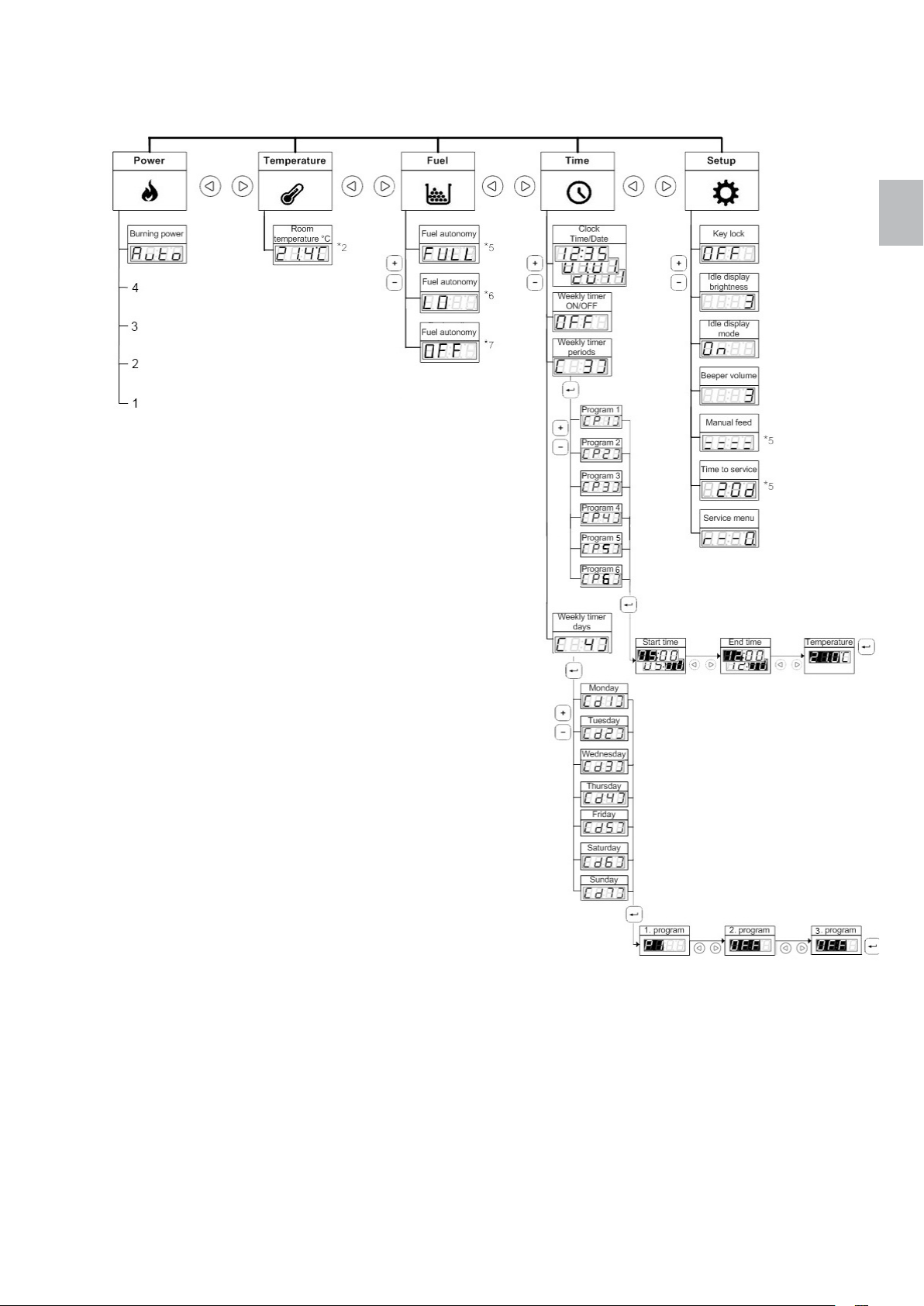
4.2. Menüstruktur ...................................................................................................... 6
4.3. Navigieren durch das Menü ................................................................................ 7
4.4. Einstellen der Uhr ............................................................................................... 7
4.5. Einstellen der Raumtemperatur .......................................................................... 7
4.6. Einstellen der Ausgangsleistung ........................................................................ 8
4.7. Einstellen der Wochenschaltprogramme ............................................................ 8
4.8. Ändern der Einrichtungsoptionen ....................................................................... 9
5. Warten der Steuereinheit ........................................................................................ 10
5.1. Austauschen der Batterie ................................................................................. 10
6. Fehlerbehebung ..................................................................................................... 11
6.1. LED-Anzeigen an der Steuereinheit ................................................................. 11
6.2. Ausfall der Stromversorgung ............................................................................ 12
6.3. Unbestimmte Fehler am Bedienfeld ................................................................. 12
7. Reinigung ............................................................................................................... 12
8. Konformitätserklärung ............................................................................................ 13
9. Garantie .................................................................................................................. 13
Funktionsschema .......................................................................................................... 53
Funktion/Komponenten – Beschreibung ........................................................................ 53
Hauptbestandteile Ofen ............................................................................................. 53
Elektro- und Elektronikbestandteile ............................................................................ 54
Feuerraumauskleidung .............................................................................................. 55
Türbestandteile .......................................................................................................... 56
Schaltplan ...................................................................................................................... 56
Montagearbeiten am Ofen ............................................................................................. 57
Seitenverkleidung und Deckel-Demontage/Montage ................................................. 57
Türscharnierjustierung oben ...................................................................................... 58
Türscharnierjustierung unten ..................................................................................... 59
Rückwandausbau ...................................................................................................... 60
Abgasschachtreinigung, Entleerung Aschebox .......................................................... 61
Filtertausch ................................................................................................................ 63
Tausch Einlagering Brenntopf .................................................................................... 64
deutsch
Page 4
HINWEISE:
deutsch
deutsch 2 Polly
1. Wichtige Informationen für den Ofenbetreiber
• Die Informationen in diesem Handbuch sind allgemeiner Natur. Nationale und europäische Normen,
örtliche und baurechtliche Vorschriften sowie feuerpolizeiliche Bestimmungen sind einzuhalten.
• Vor der Aufstellung, der Benutzung und jedem Eingriff am Kaminofen, ist diese Bedienungsanleitung
aufmerksam durchzulesen. Bewahren Sie die Bedienungsanleitung sorgfältig auf und sorgen Sie
dafür, dass sie immer neben dem Kaminofen oder in seiner Nähe zur Verfügung steht.
• Das Einhalten der hier enthaltenen Vorschriften garantiert die Sicherheit für Personen und Gerät,
einen wirtschaftlichen Betrieb und eine lange Lebensdauer. Für Planung und Konstruktion des
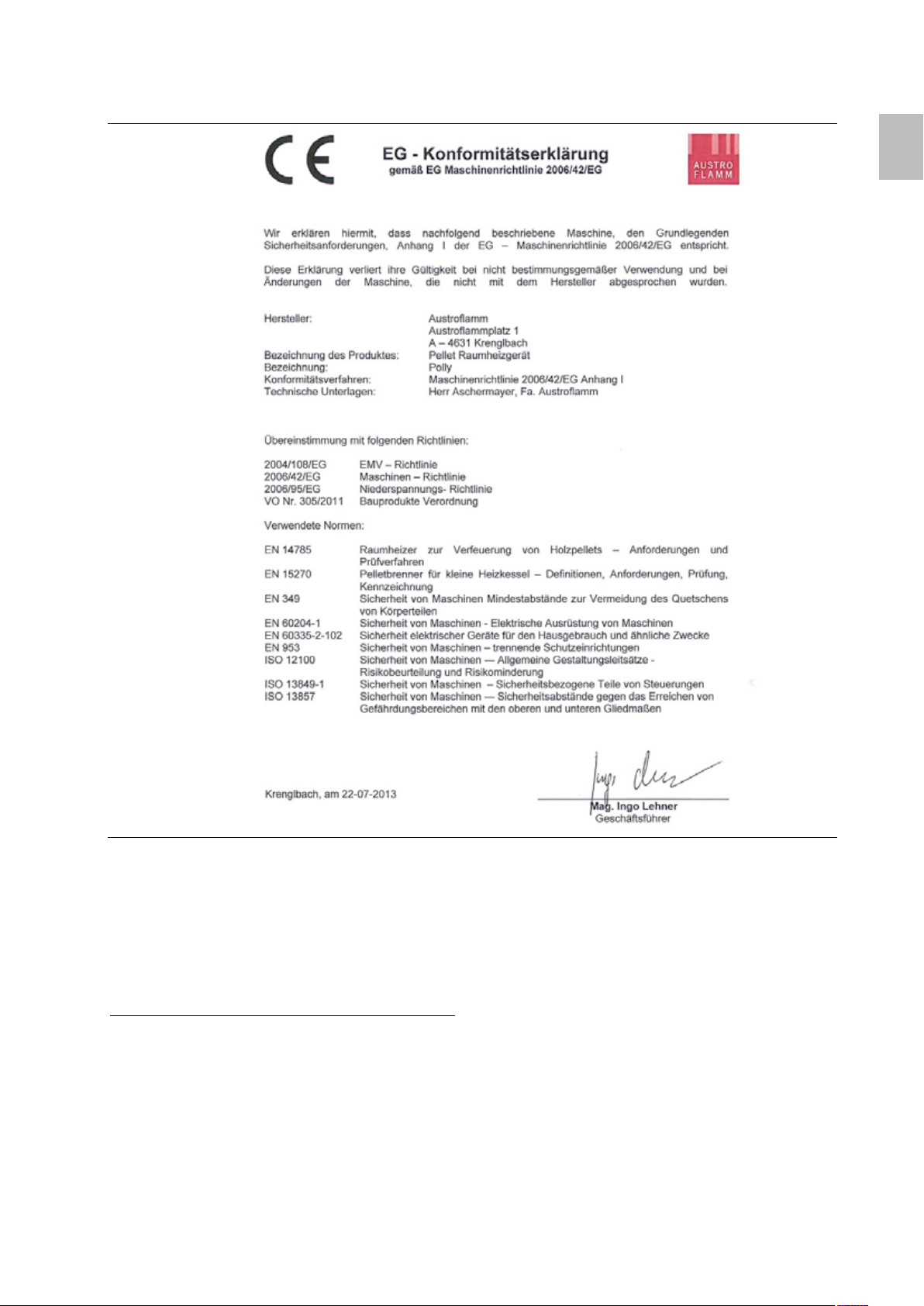
Kaminofens wurden alle unter Pkt. 8. Konformitätserklärung angeführten Normen und Richtlinien
berücksichtigt.
• Es dürfen keine Komponenten verändert oder durch Teile ersetzt werden, die keine Originalteile sind,
sonst verfällt sofort der Garantieanspruch und es erlischt die Zulassung.
• Vor jedem Eingriff die Stromzufuhr des Kaminofens unterbrechen.
• Mitgelieferte Schemen und Zeichnungen dienen nur als erläuternde Beispiele; der Hersteller verfolgt
eine Politik der ständigen Entwicklung und Aktualisierung des Produkts und kann ohne
Vorankündigung Änderungen vornehmen.
• Alle Maße dieser Bedienungsanleitung sind in mm angegeben.
• ACHTUNG: Die Erstinbetriebnahme des Gerätes darf nur durch vom Hersteller unterwiesenes
Fachpersonal erfolgen.
• Ihr Heizgerät ist nicht zur Verwendung als Leiter oder Standgerüst geeignet.
• Beachten Sie, dass sich die Oberflächen des Pelletofens während des Betriebes stark erwärmen. Zur
Bedienung des Pelletofens immer den Schutzhandschuh benutzen. Machen Sie Kinder auf die
Gefahren aufmerksam und halten Sie sie während des Betriebes von der Feuerstätte fern.
• Verwenden Sie nur Pellets, wie sie unter Pkt. 2. Brennstoff beschrieben sind.
• Das Abstellen von nicht hitzebeständigen Gegenständen auf dem Heizgerät oder in dessen Nähe ist
verboten.
• Legen Sie keine Wäschestücke zum Trocknen auf den Ofen. Auch Wäscheständer oder dgl. müssen
in ausreichendem Abstand vom Heizgerät aufgestellt werden Brandgefahr!
• Beim Betrieb Ihres Heizgerätes ist das Verarbeiten von leicht brennbaren und explosiven Stoffen im
selben oder in anschließenden Räumen verboten.
• Es muss sichergestellt sein, dass eine ausreichende Verbrennungsluftzufuhr und eine sichere
Abführung der Abgase gegeben sind. Daher immer prüfen, ob der Schornstein verstopft ist,
besonders nach längerer Betriebsunterbrechung.
• Das Konvektionsgitter darf niemals verschlossen werden, auch nicht teilweise.
• Entlüftungseinrichtungen, die zusammen mit der Feuerstätte im gleichen Raum oder Raumverbund
betrieben werden, können Probleme verursachen.
• Der Pelletofen muss je nach Verschmutzung regelmäßig gereinigt werden (siehe Pkt. 7. Reinigung,
13.5 Abgasschachtreinigung und 13.6 Filtertausch).
• Reparaturen an Ihrem Pelletofen dürfen nur durch ein vom Hersteller unterwiesenes Fachpersonal
durchgeführt werden.
• Ersatzteile je nach Bedarf und Zustand tauschen. Überprüfen sie regelmäßig die Elektro- und
Elektronikbestandteile auf Schäden oder Verschleiß (siehe auch Pkt. 11.2 Elektro- und
Elektronikbestandteile)
• Sicherheitseinrichtungen dürfen nicht überbrückt werden.
2. Brennstoff
Die Pellets sind ein Brennstoff, der durch Pressen von Sägemehl aus unbehandeltem Holz, d.h. ohne
Lack, Leim und ähnliches, hergestellt wird.
Unterschiedlichen Pelletsqualitäten verursachen in der Verbrennungsphase auch unterschiedliche
„Verkrustungen“ im Brenntopf und auf dem Rost des Kaminofens. Empfohlen wird diesbezüglich die
Verwendung von Pellets, die keine künstlichen Bindemittel enthalten und den kleinstmöglichen
unverbrannten Rückstand verursachen. Geprüft wurde der Ofen mit Pellets gem. ÖN EN 14961-2 bzw.
ENplus.
Die Verwendung von minderwertigen Pellets oder anderem Material schadet den
Funktionen Ihres Kaminofens und kann die Beendigung der Garantie und der damit
verbundenen Verantwortung des Herstellers auslösen.
Das Gerät benötigt außerdem einige Brennzyklen, bis sich die Steuerung optimal auf Ihre
Umgebungsbedingungen eingestellt hat.
Page 5
Polly 3 deutsch
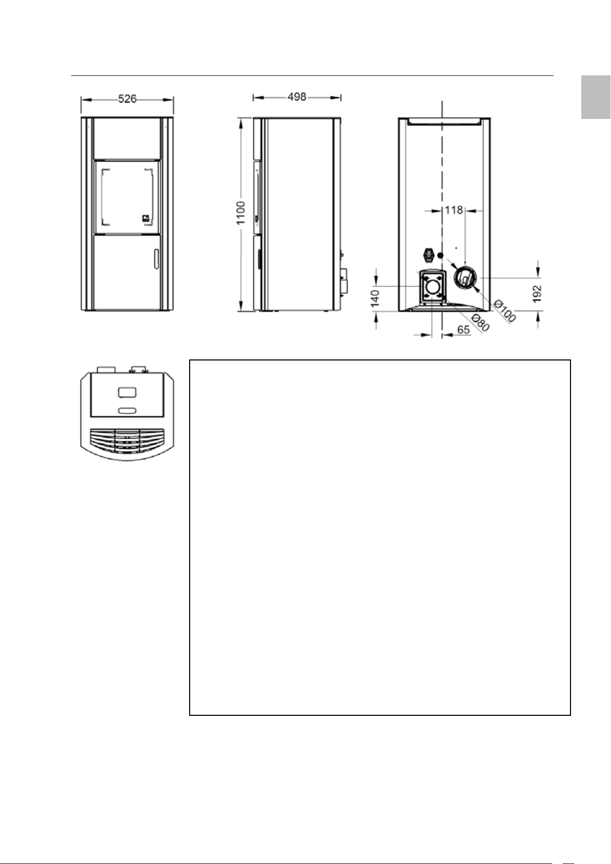
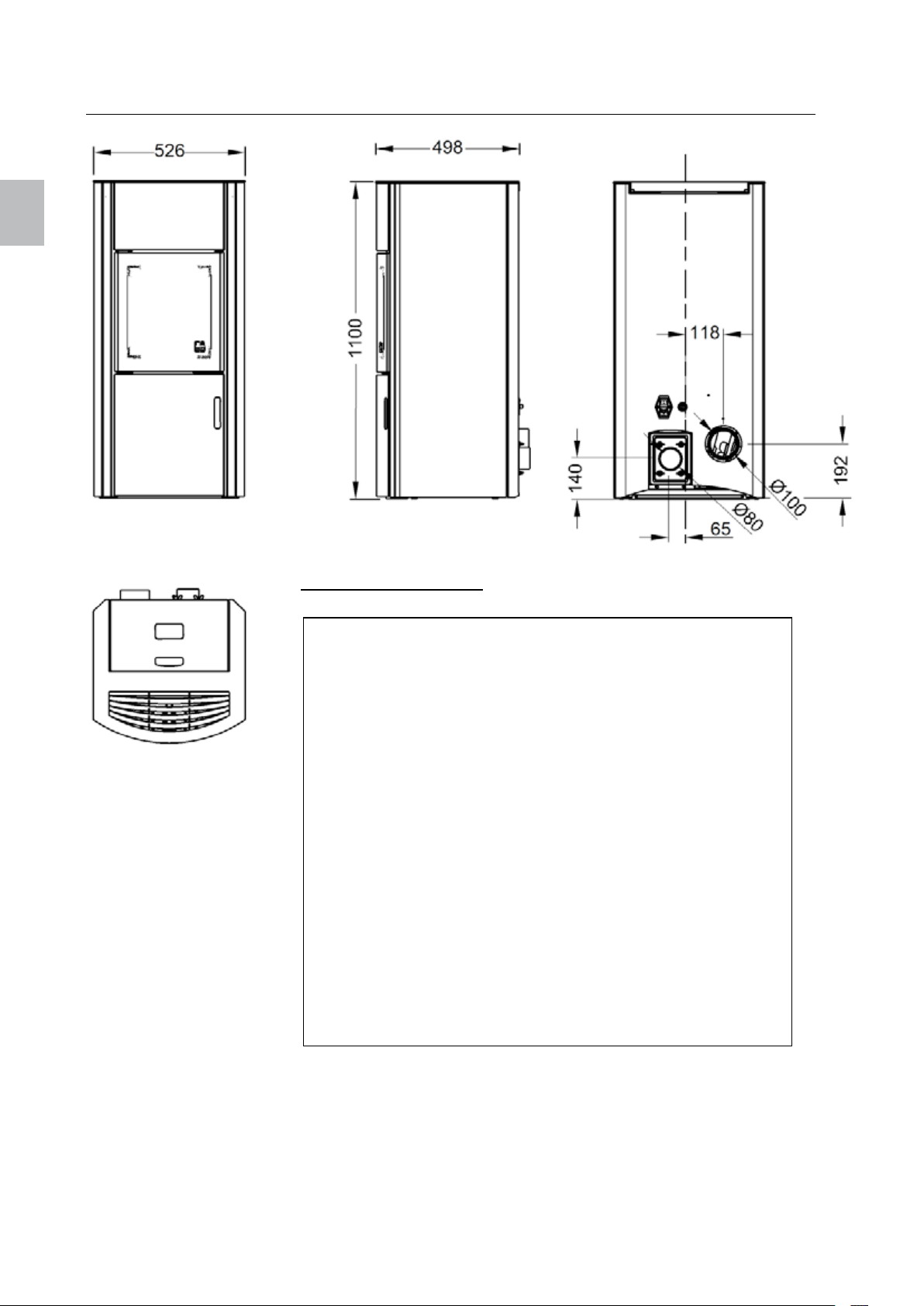
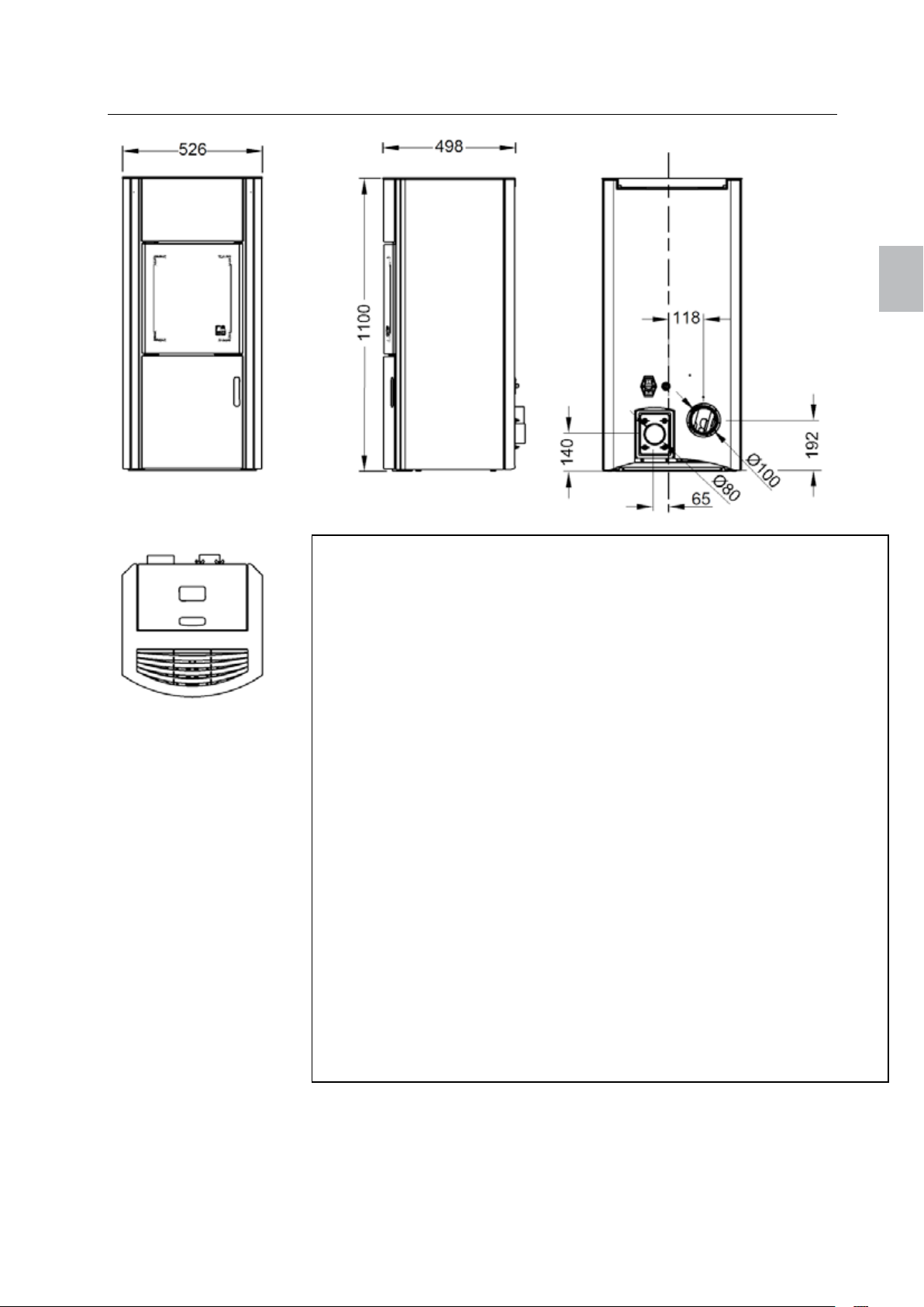
3. Außenmaße und technische Daten
deutsch
Nennwärmeleistung (NWL) 8 kW
Teillast-Wärmeleistung 2,4 kW
Raumheizvermögen 55 – 190 m³
Wirkungsgrad >90 %
CO-Gehalt bei NW <180 mg/Nm³
CO-Gehalt bei Teillast 155 mg/Nm³
Abgastemperatur bei NW 150 °C
Abgasmassenstrom bei NWL 4,4 g/s
Abgasmassenstrom bei Teillast 3,2 g/s
Fassungsvermögen Fülltank 26 kg / 40 l
Brennstoff Pellet
Pelletsverbrauch min./max 0,6 – 1,8 kg/h
Autonomie min./max ca. 12 - 40 h
Luftstutzen-Ø 80 mm
Abgasstutzen-Ø 100 mm
Stromstärke beim Einschalten 300 W
Stromstärke bei Betrieb 50 W
Spannung / Frequenz Strom 230 V / 50 Hz
Spannungsschwankungen 0,9 - 1,1 der Nennspannung
Frequenzschwankungen 0,99 - 1,01 der Nennfrequenz dauernd
0,98 - 1,02 kurzzeitig
Maße H x B x T 1100 x 526 x 498 mm
Gewicht 150 kg
Mindestabstand seitlich 150 mm
hinten 100 mm
vorne 800 mm
Temperaturgrenzen 0 - 40°C
relative Luftfeuchte nicht kondensierend
Aufstellungsort Seehöhe < 1000 m
Page 6
deutsch 4 Polly
deutsch
4. Verwenden des Bedienfelds
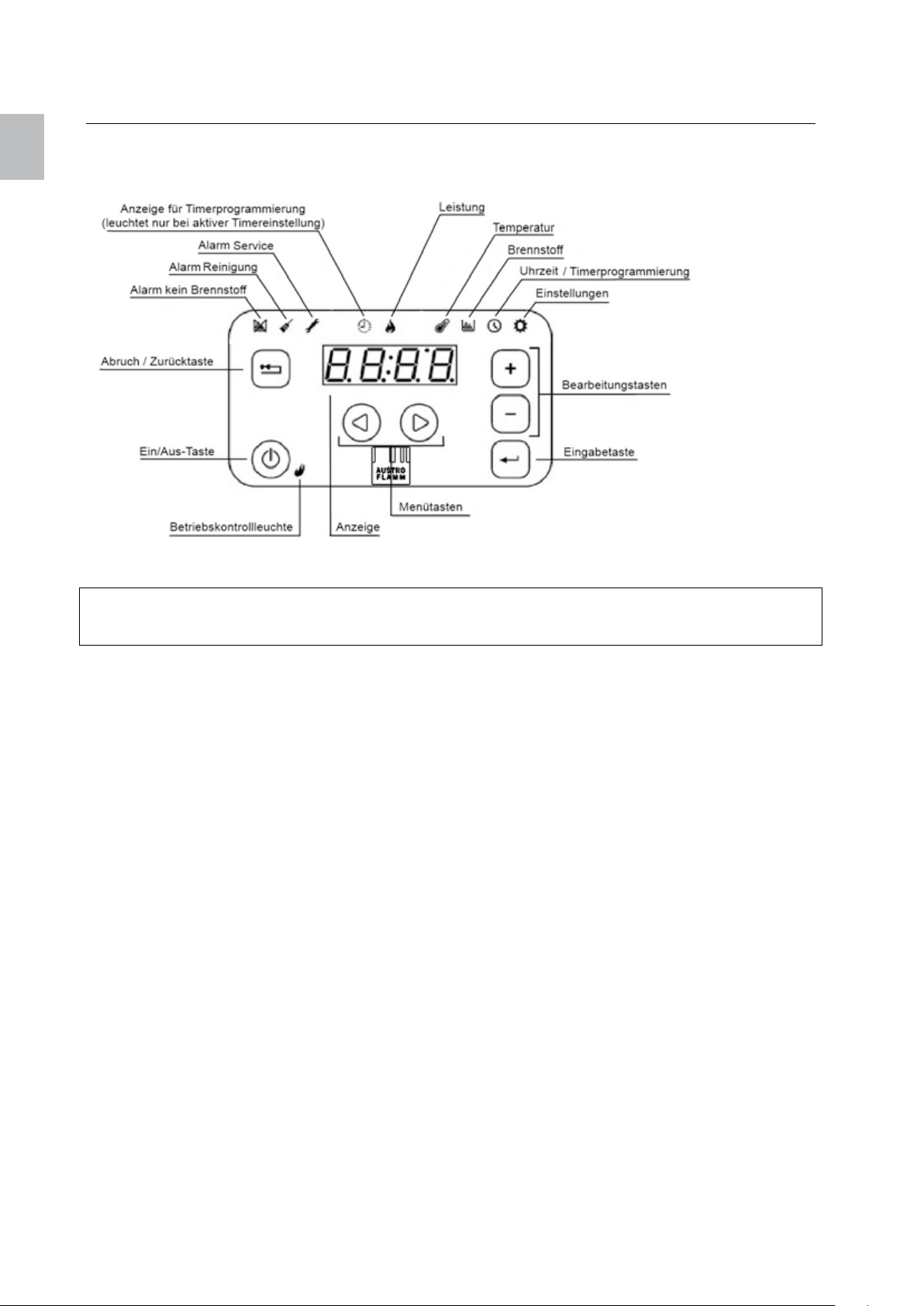
4.1. Bedienfeld
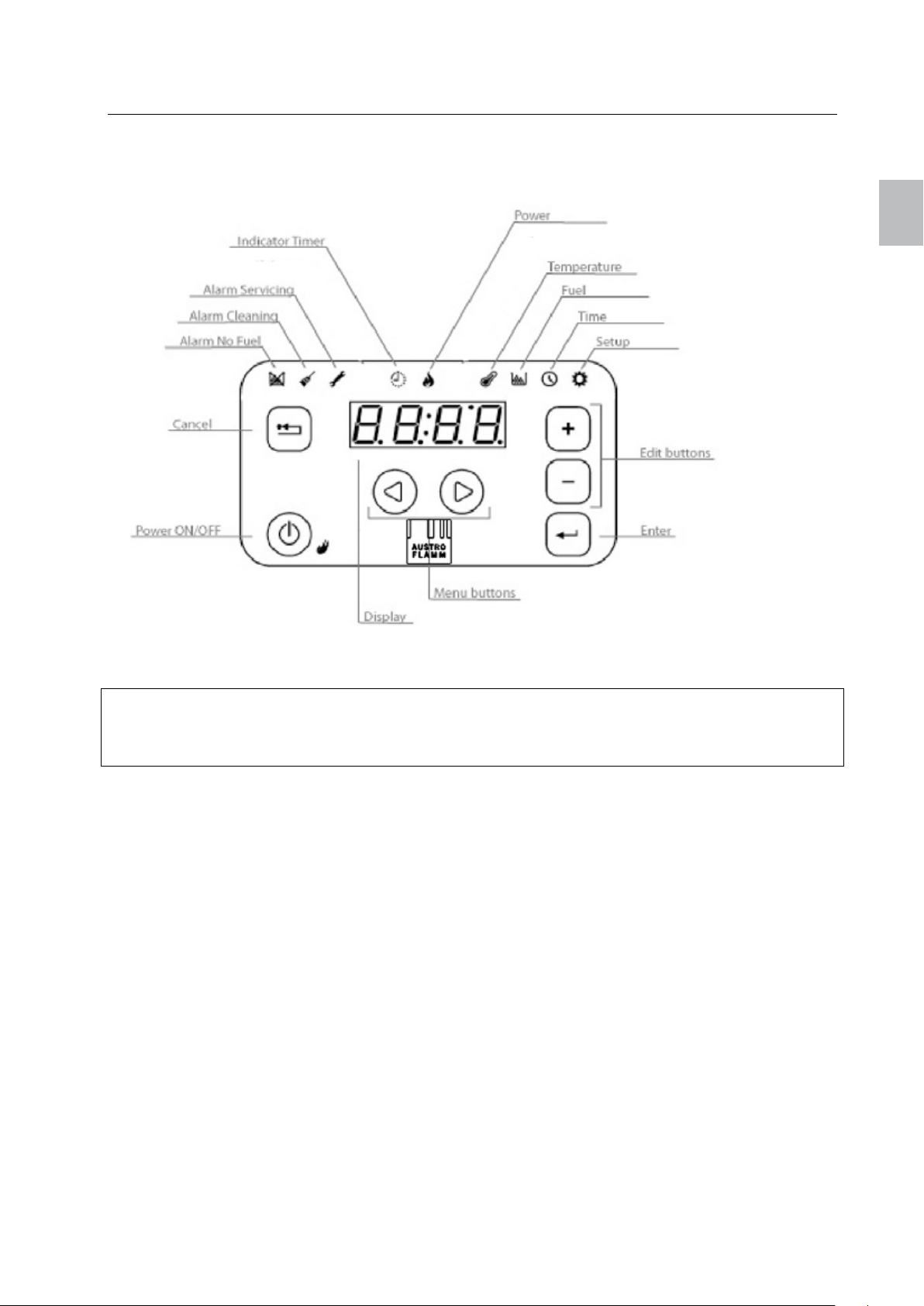
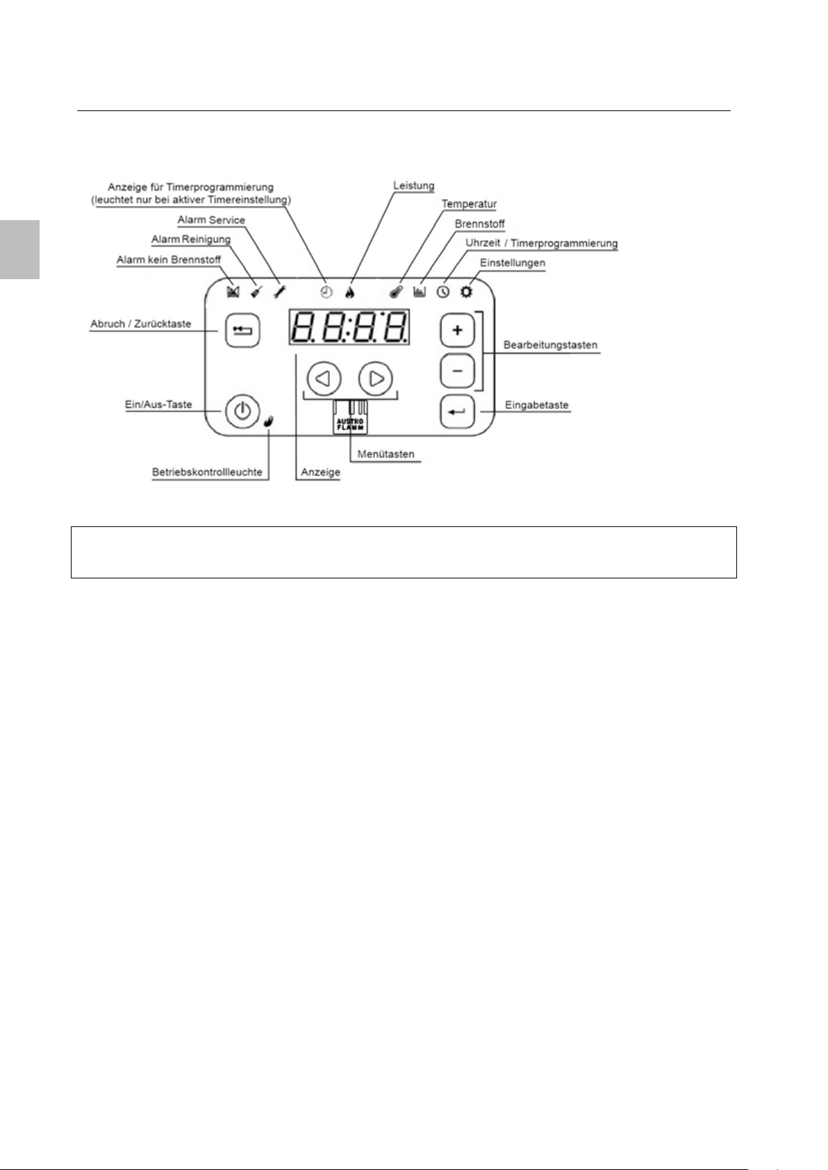
Abbildung 1: Bedienfeld
Hinweis
Halten Sie das Bedienfeld für eine optimale Leistung stets sauber. Flecken auf den Tasten, wie etwa Fett,
können ein Signal auslösen, als ob die Taste gedrückt wurde.
Das Touch-Bedienfeld ist intuitiv aufgebaut. Am oberen Rand des Bedienfelds befinden sich Anzeigen für
verschiedene Alarme, den Zeitschaltuhrbetrieb und Menüs.
Das Display zeigt die eingestellten oder aktuellen Werte für die gegenwärtig ausgewählte Menüoption.
Die Tasten dienen zur Navigation durch das Menü und zur Steuerung des Betriebs der Steuereinheit.
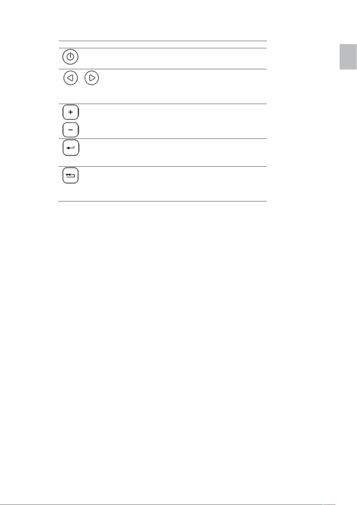
Eine Beschreibung der Tasten finden Sie in
Tabelle 1: Tasten des Bedienfelds auf Seite 5.
Das Bedienfeld verfügt außerdem über einen Summer, der Feedback-Signale des Bedienfelds ausgibt.
Folgende Signaltöne sind möglich:
• Kurzer hoher Ton: Ertönt beim Navigieren durch das Menü und Bearbeiten der Einstellungen.
• Langer tiefer Ton: Ertönt im Fall einer unzulässigen Aktion (falsche Taste gedrückt).
• Langer hoher Ton: Im Fall eines Alarms wird dieser Ton in der vom Benutzer eingestellten
Lautstärke ausgegeben, im Fall eines Fehlers hingegen ertönt dieser Ton mit voller Lautstärke.
Eine Beschreibung der Alarme und Fehler finden Sie in Kapitel Fehlerbehebung auf Seite 11.
Page 7
Polly 5 deutsch
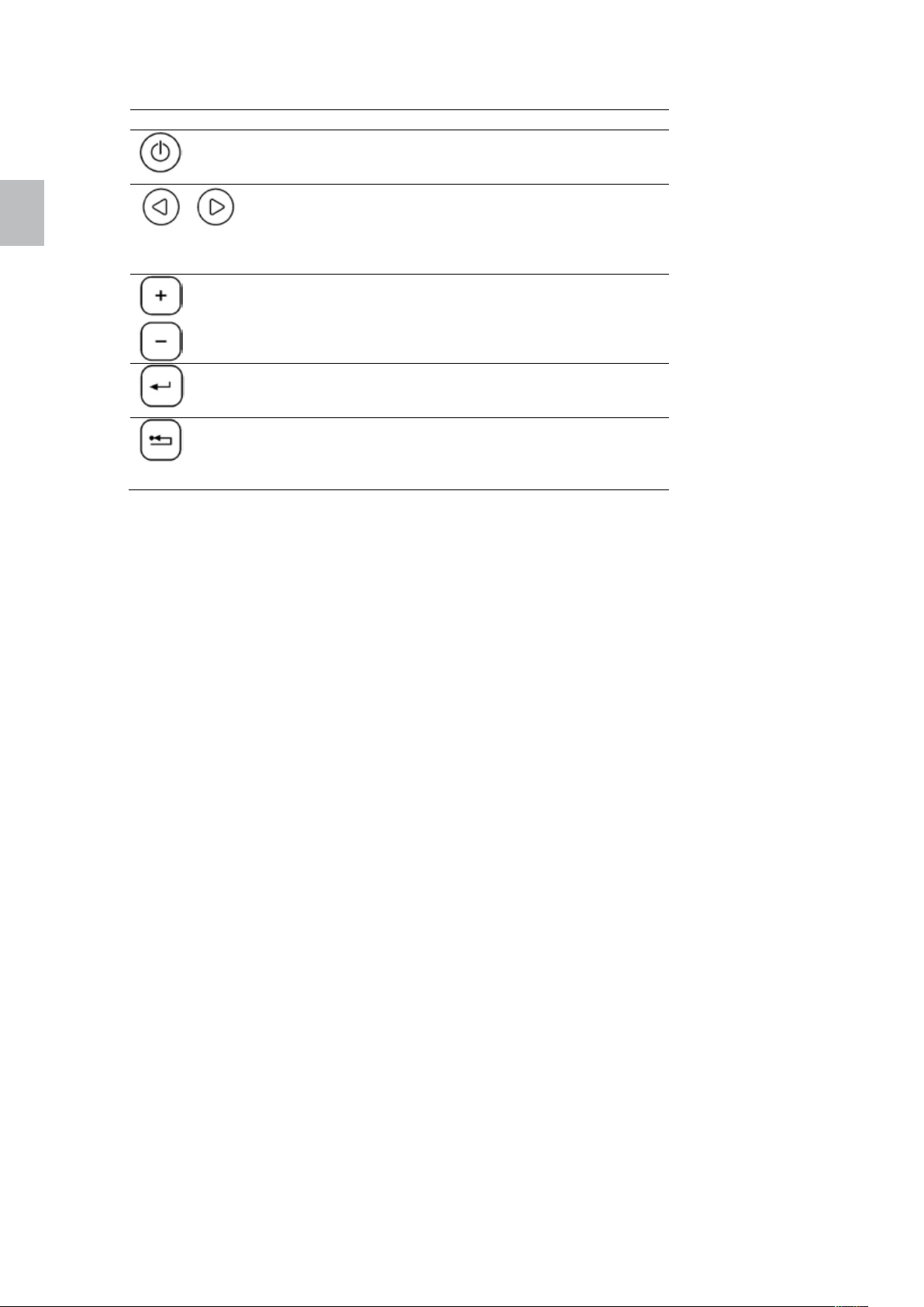
Taste Beschreibung
Mit der Ein-/Aus-Taste wird die Feuerstätte ein- oder
Tabelle 1: Tasten des Bedienfelds
ausgeschaltet. Dazu die Taste 1 Sekunde lang
gedrückt halten.
Die Menütasten (Pfeiltasten) dienen zum Navigieren
durch die erste Menüebene. Das gegenwärtig
ausgewählte Menü wird durch das entsprechende
Symbol am oberen Rand angezeigt. Diese Tasten
werden auch im Bearbeitungsmodus verwendet.
Die Bearbeitungstasten (Plus- und Minus-Taste)
dienen zum Navigieren durch die Untermenüs sowie
zum Erhöhen/Verringern von Werten im
Bearbeitungsmodus, wenn der ausgewählte Wert
blinkt.
Mit der Eingabetaste wird der Bearbeitungsmodus
aufgerufen. Außerdem dient sie zum Bestätigen der
eingestellten Werte bzw. zum Auswählen weiterer
Untermenüs.
Die Abbruchtaste dient zum Verwerfen der
Änderungen und zum Zurückgehen zur nächst
höheren Menüebene. Wird diese Taste länger als
3 Sekunden gedrückt gehalten, wird der letzte Fehleroder Alarmcode angezeigt.
deutsch
Page 8
deutsch
deutsch 6 Polly
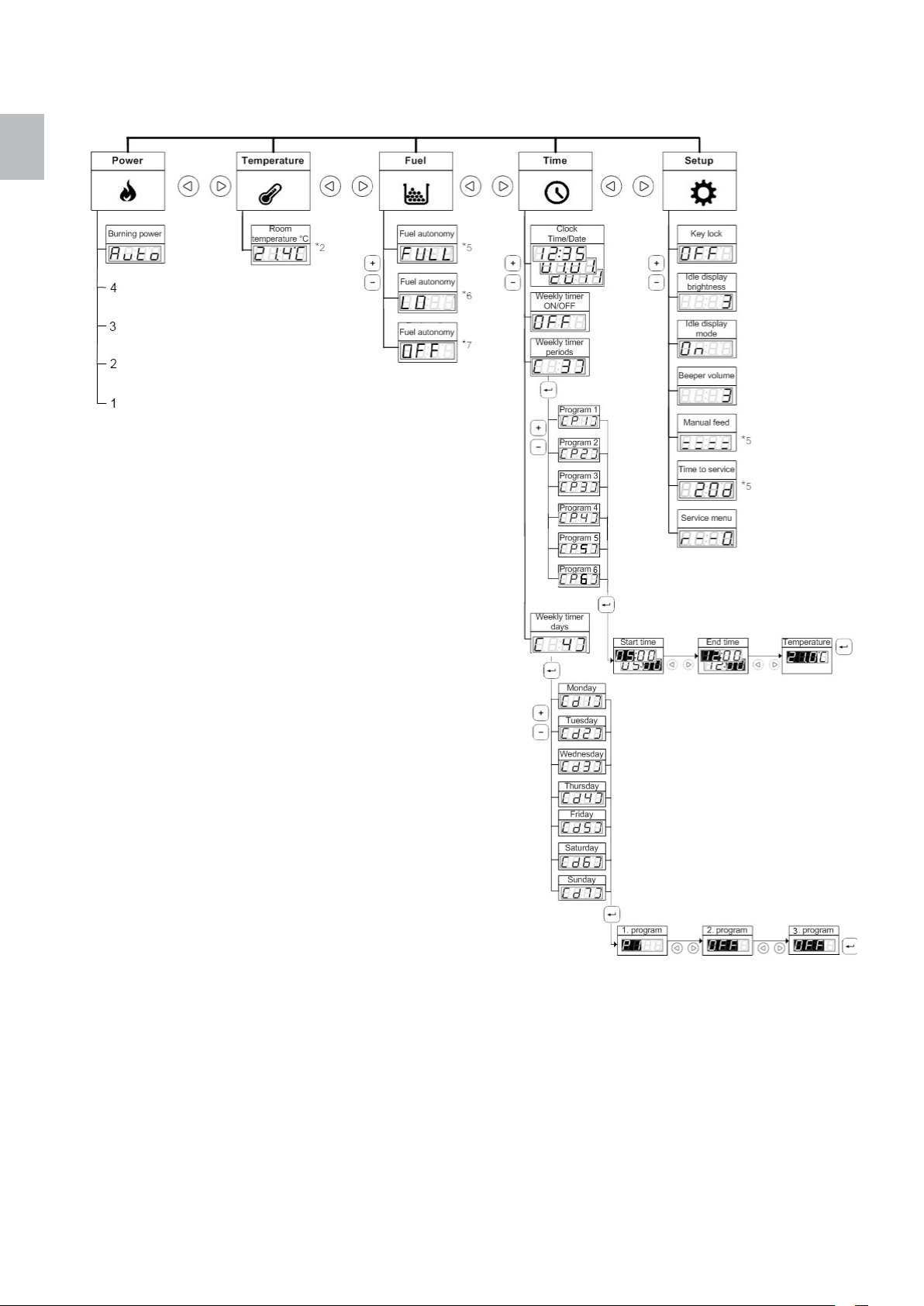
4.2. Menüstruktur
Abbildung 2: Menüstruktur
Page 9

Polly 7 deutsch
4.3. Navigieren durch das Menü
Mit der linken und rechten Pfeiltaste können Sie durch die erste Menüebene navigieren. Das Symbol für
das ausgewählte Menü leuchtet. Am Display wird die Einstellung für den ersten Untermenüeintrag
angezeigt.
Mit der Plus- und Minus-Taste können Sie in der zweiten Menüebene (dem Untermenü) nach oben und
unten navigieren. Die in der Abbildung 2 dargestellte Menüstruktur ist umgekehrt, sodass es aussieht, als
ob Sie sich im Menü nach unten bewegen würden, tatsächlich bewegen Sie sich jedoch nach oben. Zur
einfacheren Navigation durch die zweite Menüebene wird die Nummer des entsprechenden
Menüeintrags kurz in Klammern angezeigt.
Zum Ändern einer Einstellung im Menü drücken Sie die Eingabetaste. Dadurch wird der
Bearbeitungsmodus für die ausgewählte Einstellung aktiviert. Der Anzeigewert beginnt zu blinken.
Ändern Sie den Wert mit der Plus- und Minus-Taste. Mit der linken und rechten Pfeiltaste können Sie
durch die Schritte im Bearbeitungsmodus gehen. Drücken Sie abschließend die Eingabetaste, um die
Einstellung zu speichern und den Bearbeitungsmodus zu verlassen. Am Display wird wieder der
Menüeintrag angezeigt, den Sie bearbeitet haben.
Das Display zeigt entweder den eingestellten oder den tatsächlichen Wert an, je nach der Einstellung. Bei
der Änderung der Temperatur beispielsweise geben Sie die gewünschte Raumtemperatur ein. Nachdem
Sie den Bearbeitungsmodus verlassen haben, wird am Display die tatsächliche Temperatur angezeigt
(die von der eingestellten Temperatur abweichen kann).
Um die dritte Menüebene aufzurufen, drücken Sie die Eingabetaste. Mit der Plus- und Minus-Taste
können Sie dann von Menüeintrag zu Menüeintrag gehen. Die Vorgehensweise zum Ändern der
Einstellungen ist die gleiche wie auf der zweiten Menüebene.
Um den Bearbeitungsmodus zu verlassen, ohne die Änderungen zu speichern, drücken Sie die
Abbruchtaste. Mit dieser Taste können Sie auch eine Ebene im Menü zurückgehen. Wenn Sie
beispielsweise Programm 3 im Menüeintrag "Weekly Timer Periods" (Wochenschaltzeiten) bearbeiten,
können Sie mit der Abbruchtaste die Änderungen verwerfen und zu Programm 3 zurückkehren. Durch
Drücken der Abbruchtaste gelangen Sie zu "Weekly Timer Periods" (Wochenschaltzeiten), dann zu
"Clock" (Uhr) und schließlich zu "Burning Power" (Brennleistung) im Menü "Power" (Leistung).
deutsch
4.4. Einstellen der Uhr
Am Bedienfeld können die aktuelle Uhrzeit und das aktuelle Datum eingestellt werden. Um die aktuelle
Uhrzeit anzuzeigen, gehen Sie durch Drücken der Menütaste zum Menü „Time“ (Uhrzeit). Am Display
wird die aktuelle Uhrzeit angezeigt.
Um Uhrzeit und Datum einzustellen, drücken Sie im Menü „Time“ (Uhrzeit) die Eingabetaste. Der
Stundenwert blinkt. Stellen Sie mit den Bearbeitungstasten die gewünschte Stunde ein. Drücken Sie
dann die rechte Menütaste. Der Minutenwert blinkt. Stellen Sie die gewünschten Minuten ein. Drücken
Sie die rechte Menütaste und stellen Sie das Datum auf die gleiche Weise ein. Das Datum wird im
Format tt.mm.jjjj festgelegt. Drücken Sie dann die rechte Menütaste und stellen Sie den Wochentag ein.
Wählen Sie die entsprechende Nummer zwischen 1 (Montag) und 7 (Sonntag) aus. Bestätigen Sie die
Uhrzeit- und Datumseinstellung durch Drücken der Eingabetaste.
4.5. Einstellen der Raumtemperatur
Die Steuereinheit bietet zwei Möglichkeiten zum Einstellen der Raumtemperatur. Diese sind:
- Verwenden von Wochenschaltprogrammen
- Manuelles Einstellen oder Ändern der Raumtemperatur
Mithilfe der Wochenschaltprogramme können Sie den Betrieb der Feuerstätte voll automatisieren, sodass
nur wenige oder keine Benutzeraktionen erforderlich sind. Ausführliche Informationen dazu finden Sie im
Kapitel Einstellen der Wochenschaltprogramme auf Seite 8.
Page 10
deutsch
deutsch 8 Polly
Sie können die Raumtemperatur auch manuell einstellen bzw. ändern. Bei Verwendung der
Wochenschaltprogramme können Sie die Programmeinstellungen vorübergehend außer Kraft setzen. Die
Programmeinstellungen werden zurückgesetzt, wenn bestimmte, für die Zeitschaltuhr festgelegte
Bedingungen erfüllt sind (wenn zum Beispiel der Endzeitpunkt erreicht ist und sich die Feuerstätte
abschaltet).
Um die aktuelle Raumtemperatur anzuzeigen, gehen Sie durch Drücken der Menütaste zum Menü
„Temperature“ (Temperatur). Am Display wird die aktuelle Raumtemperatur angezeigt.
Um die gewünschte Raumtemperatur einzustellen, drücken Sie im Menü „Temperature“ (Temperatur) die
Eingabetaste. Am Display wird dann die eingestellte Solltemperatur im Bearbeitungsmodus angezeigt
(der Wert blinkt). Sie können diesen Wert mit den Bearbeitungstasten erhöhen oder verringern. Drücken
Sie abschließend zur Bestätigung der eingestellten Temperatur die Eingabetaste. Am Display wird die
aktuelle Raumtemperatur angezeigt.
4.6. Einstellen der Ausgangsleistung
Die Steuereinheit reguliert die Feuerstätte so, dass eine optimale Leistung sichergestellt ist. Sie können
diese Einstellungen außer Kraft setzen und die Brennleistung verringern und somit Brennstoff sparen.
Diese Einstellungen beeinflussen die Brennstoffzuführung und die Gebläsegeschwindigkeit. Die
gewünschte Raumtemperatur wird dadurch langsamer erreicht und es kann zu rascherer (Scheiben)verschmutzung kommen.
Die Einstellung der Brennleistung bezieht sich auf die maximale Brennleistung, die die Feuerstätte zum
Heizen der Umgebung aufwendet. Wenn die eingestellte Solltemperatur erreicht ist, wird die
Brennleistung automatisch gedrosselt.
Um die aktuelle Brennleistung anzuzeigen, gehen Sie durch Drücken der Menütaste zum Menü „Power“
(Leistung). Am Display wird die aktuelle Brennleistung angezeigt.
Zum langsameren Aufheizen auf die gewünschte Raumtemperatur können Sie die Einstellung der
Brennleistung drosseln. Drücken Sie dazu im Menü „Power“ (Leistung) die Eingabetaste. Am Display wird
die Brennleistung im Bearbeitungsmodus angezeigt (der Wert blinkt). Sie können diesen Wert mit den
Bearbeitungstasten zwischen Automatik (max. Leistung), 4, 3, 2, oder 1 (min. Leistung) einstellen.
Drücken Sie abschließend zur Bestätigung der eingestellten Brennleistung die Eingabetaste. Am Display
wird die aktuelle Brennleistung angezeigt.
4.7. Einstellen der Wochenschaltprogramme
Mit der Steuereinheit können Sie Wochenschaltprogramme einstellen und so den Betrieb der Feuerstätte
automatisieren. Es können sechs verschiedene Programme eingestellt werden, wobei für jeden
Wochentag max. drei Programme ausgewählt werden können. Das Programm legt den Start- und
Endzeitpunkt sowie die gewünschte Temperatur fest.
Um ein Programm einzustellen, rufen Sie durch Drücken der Menütaste das Menü „Time“ (Uhrzeit) auf.
Wählen Sie dann durch Drücken der Bearbeitungstaste den Eintrag „Weekly timer periods“
(Wochenschaltzeiten) aus. Am Display wird [ 3 ] angezeigt. Drücken Sie die Eingabetaste, um „Program
1“ (Programm 1) auszuwählen. Am Display wird [ P1 ] angezeigt. Drücken Sie die Eingabetaste erneut,
um in den Bearbeitungsmodus für Programm 1 zu wechseln. Der Stundenwert des Startzeitpunkts blinkt.
Stellen Sie mit den Bearbeitungstasten die gewünschte Stunde für den Startzeitpunkt ein. Drücken Sie
dann die rechte Menütaste. Der Minutenwert des Startzeitpunkts blinkt. Stellen Sie die gewünschten
Minuten des Startzeitpunkts ein. Drücken Sie die rechte Menütaste und stellen Sie den gewünschten
Endzeitpunkt ein. Drücken Sie dann die rechte Menütaste, um die gewünschte Raumtemperatur für den
ausgewählten Zeitraum einzustellen. Bestätigen Sie die Programmeinstellungen durch Drücken der
Eingabetaste. Wiederholen Sie die obigen Schritte zum Einstellen der anderen Programme.
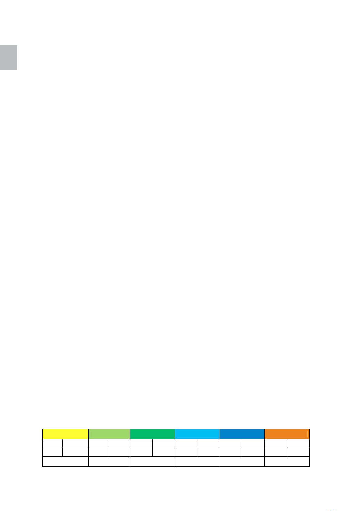
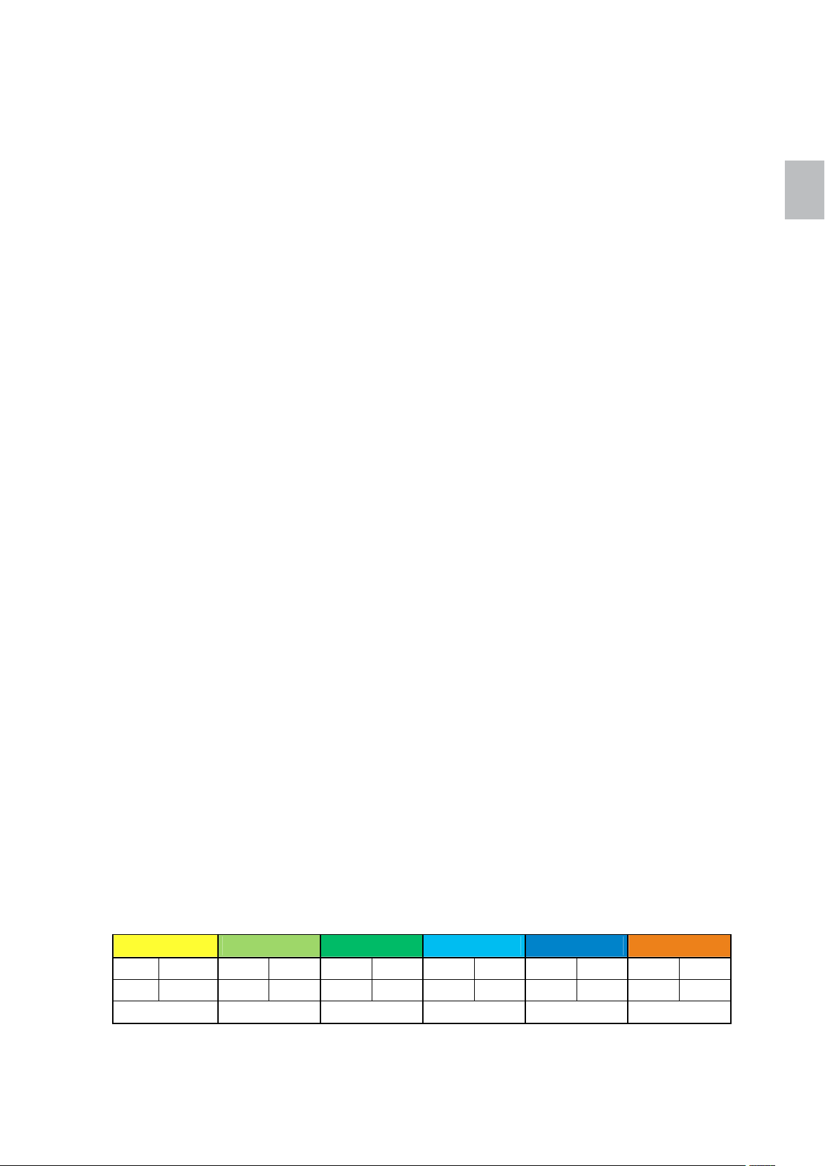
Beispiel:
Programm 1 Programm 2 Programm 3 Programm 4 Programm 5 Programm 6
AN AUS AN AUS AN AUS AN AUS AN AUS AN AUS
5:30 07:30 08:00 11:30 12:00 23:00 17:00 23:00 20:00 22:30 04:00 07:00
16 °C 18 °C 19 °C 18 °C 17 °C 15 °C
Page 11
Polly 9 deutsch
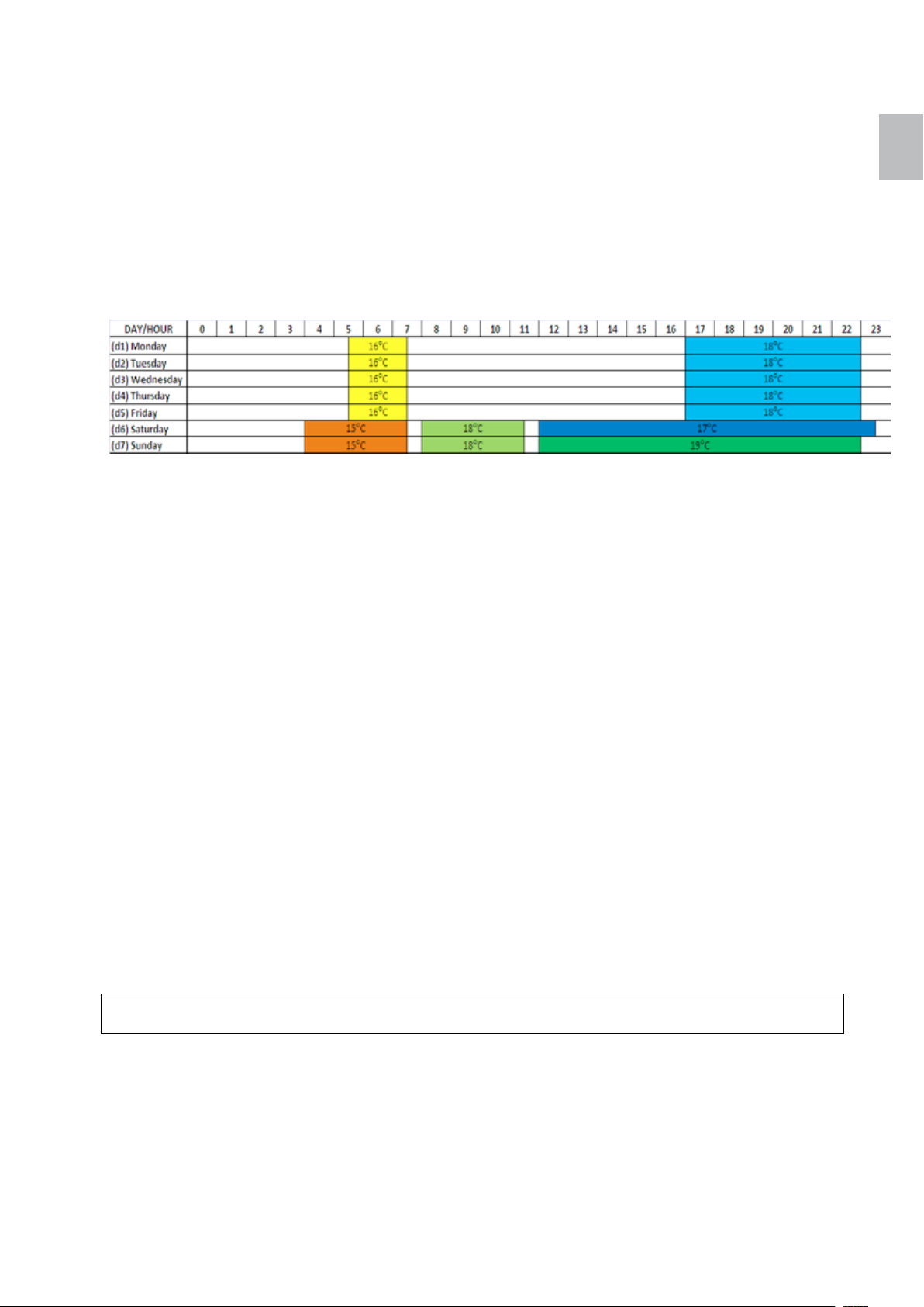
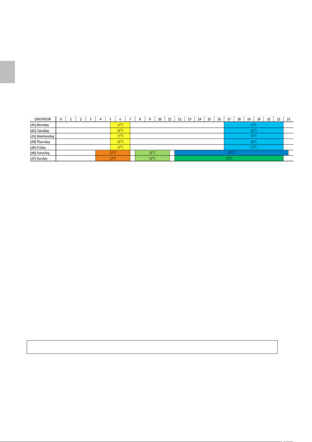
Um die Programme den Wochentagen zuzuordnen, rufen Sie durch Drücken der Menütaste das Menü
„Time“ (Uhrzeit) auf. Wählen Sie dann durch Drücken der Bearbeitungstaste den Eintrag „Weekly timer
days“ (Wochenschalttage) aus. Am Display wird [ 4 ] angezeigt. Drücken Sie die Eingabetaste, um
„Monday“ (Montag) auszuwählen. Am Display wird [ d1 ] angezeigt. Drücken Sie die Eingabetaste erneut,
um in den Bearbeitungsmodus für Montag zu wechseln. Der Wert für das 1. Programm blinkt. Stellen Sie
mit den Bearbeitungstasten das gewünschte Programm ein. Drücken Sie dann die rechte Menütaste. Der
Wert für das 2. Programm blinkt. Stellen Sie das gewünschte Programm ein. Wenn Sie nicht alle
Programmplätze verwenden wollen, dann stellen sie dies mit der Minus-Taste auf [ OFF ]. Bestätigen Sie
die Programmeinstellungen durch Drücken der Eingabetaste. Wiederholen Sie die obigen Schritte zum
Einstellen der Programme für alle Wochentage.
Beispiel:
deutsch
Um den Betrieb der Feuerstätte mit den Wochenschaltprogrammen zu aktivieren oder deaktivieren, rufen
Sie durch Drücken der Menütaste das Menü Time (Uhrzeit) auf. Wählen Sie dann durch Drücken der
Bearbeitungstaste den Eintrag „Weekly timer ON/OFF“ (Wochenschaltuhr ein/aus) aus. Drücken Sie die
Eingabetaste und schalten Sie die Wochenschaltuhr entweder ein (ON) oder aus (OFF). Wenn Sie die
Wochenschaltuhr deaktivieren, konfigurieren Sie den Betrieb der Feuerstätte manuell.
4.8. Ändern der Einrichtungsoptionen
Im Menü „Setup“ (Einrichtung) können die Optionen für:
[ 1 ]… "Key lock" (Tastensperre)
[ 2 ]… "Idle display brightness" (Display-Helligkeit im Ruhezustand)
[ 3 ]… "Idle display mode" (Display-Ruhezustand)
[ 4 ]… "Beeper volume" (Summerlautstärke) und
[ 6 ]… "Manual feed" (Manuelle Zuführung)
eingestellt werden.
Mit der Option „Key lock“ (Tastensperre) kann das Bedienfeld gesperrt werden, sodass keine
versehentlichen Änderungen an den Einstellungen möglich sind. Bei aktivierter Tastensperre können Sie
durch das Menü navigieren und die aktuellen Werte anzeigen, Sie können jedoch keine der Einstellungen
bearbeiten, mit Ausnahme der Tastensperre selbst. Die Einstellung Key lock (Tastensperre) bietet
folgende Optionen:
- OFF (Aus): Die Tastensperre ist deaktiviert, alle Tasten können betätigt werden.
- Lo (Niedrig): Der Bearbeitungsmodus ist deaktiviert (die Eingabetaste ist gesperrt).
- Hi (Hoch): Der Bearbeitungsmodus und die Ein-/Ausschaltfunktion sind deaktiviert (die
Eingabetaste und die Ein-/Aus-Taste sind gesperrt).
Tipp!
Wir empfehlen, die Tastensperre beim Reinigen des Bedienfelds zu aktivieren.
Sie können die Helligkeit des Displays im Ruhezustand erhöhen oder verringern, um Energie zu sparen.
Sobald Sie das Bedienfeld berühren, erhöht sich die Helligkeit des Displays auf den Standardwert.
Die Einstellung „Idle display mode“ (Display-Ruhezustand) bietet folgende Optionen:
- OFF (Aus): Das Bedienfeld bleibt im ausgewählten Menü. Wenn der Bearbeitungsmodus aktiv
war, werden die Änderungen verworfen und der Bearbeitungsmodus wird verlassen.
Page 12
deutsch
deutsch 10 Polly
- Option 1: Das Bedienfeld verlässt das aktuelle Menü und zeigt abwechselnd die aktuelle
Raumtemperatur und Uhrzeit an.
- Option 2: Das Bedienfeld verlässt das aktuelle Menü und öffnet das Menü „Temperature“
(Temperatur). Am Display wird die aktuelle Raumtemperatur angezeigt.
- Option 3: Das Bedienfeld verlässt das aktuelle Menü und öffnet das Menü „Clock“ (Uhr). Am
Display wird die aktuelle Uhrzeit angezeigt.
Die Einstellung „Beeper volume“ (Summerlautstärke) steuert die Lautstärke der akustischen Signale des
Bedienfelds.
Mit der Option „Manual feed“ (Manuelle Zuführung) kann die Pelletzuführung manuell gestartet werden.
Die Zuführung arbeitet für einen kurzen Zeitraum und stoppt dann. Mit dieser Option können Sie die
Zuführung reinigen oder leeren bzw. neu füllen.
Um die Einrichtungsoptionen zu ändern, gehen Sie durch Drücken der Menütaste zum Menü „Setup“
(Einrichtung). Die eingestellte Display-Helligkeit im Ruhezustand wird angezeigt. Mit den
Bearbeitungstasten können Sie die Einstellungen der einzelnen Einrichtungsoptionen anzeigen. Um eine
Einstellung zu ändern, drücken Sie die Eingabetaste und erhöhen/verringern Sie den Wert mithilfe der
Bearbeitungstasten. Drücken Sie abschließend zur Bestätigung des eingestellten Werts die Eingabetaste.
5. Warten der Steuereinheit
5.1. Austauschen der Batterie
Die Steuereinheit schaltet während eines Stromausfalls oder bei Trennung von der Netzstromversorgung
auf interne Batterieversorgung um. Die Batterie versorgt die interne Uhr und den internen Speicher des
Mikroprozessors.
Wenn die Batterie leer ist, funktioniert die Steuereinheit normal, solange sie an die Netzstromversorgung
angeschlossen ist. Bei einem Stromausfall stoppt die interne Uhr und die Betriebsphase wird nicht im
Speicher gespeichert. Nach Wiederherstellung der Stromversorgung wird die Uhr zurückgesetzt und die
Steuereinheit bleibt in der Phase OFF (Aus) (Ofenmodus) bzw. „Fire up“ (Anheizen) (Kesselmodus).
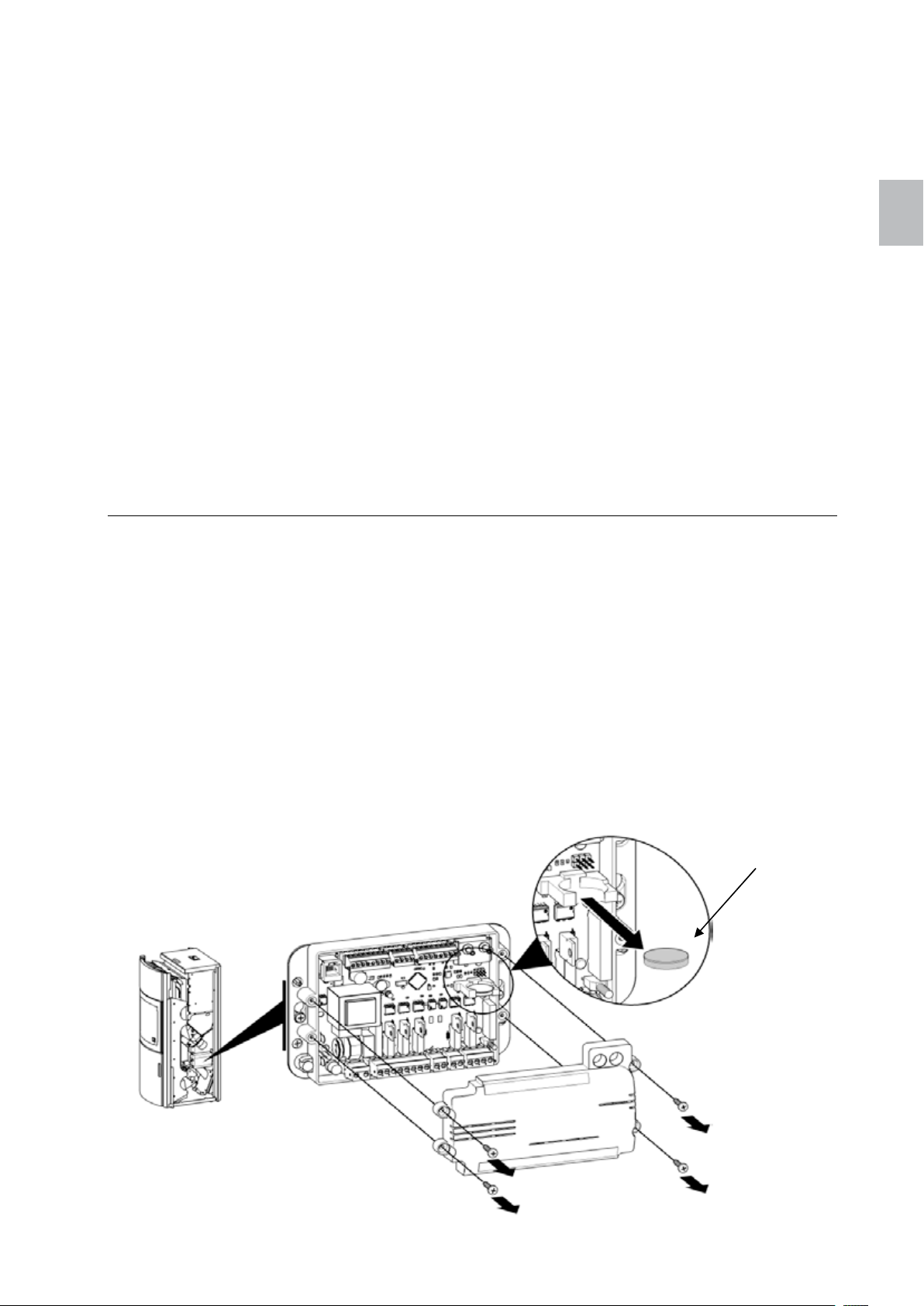
So tauschen Sie die Batterie aus:
1. Trennen Sie die Netzstromversorgung.
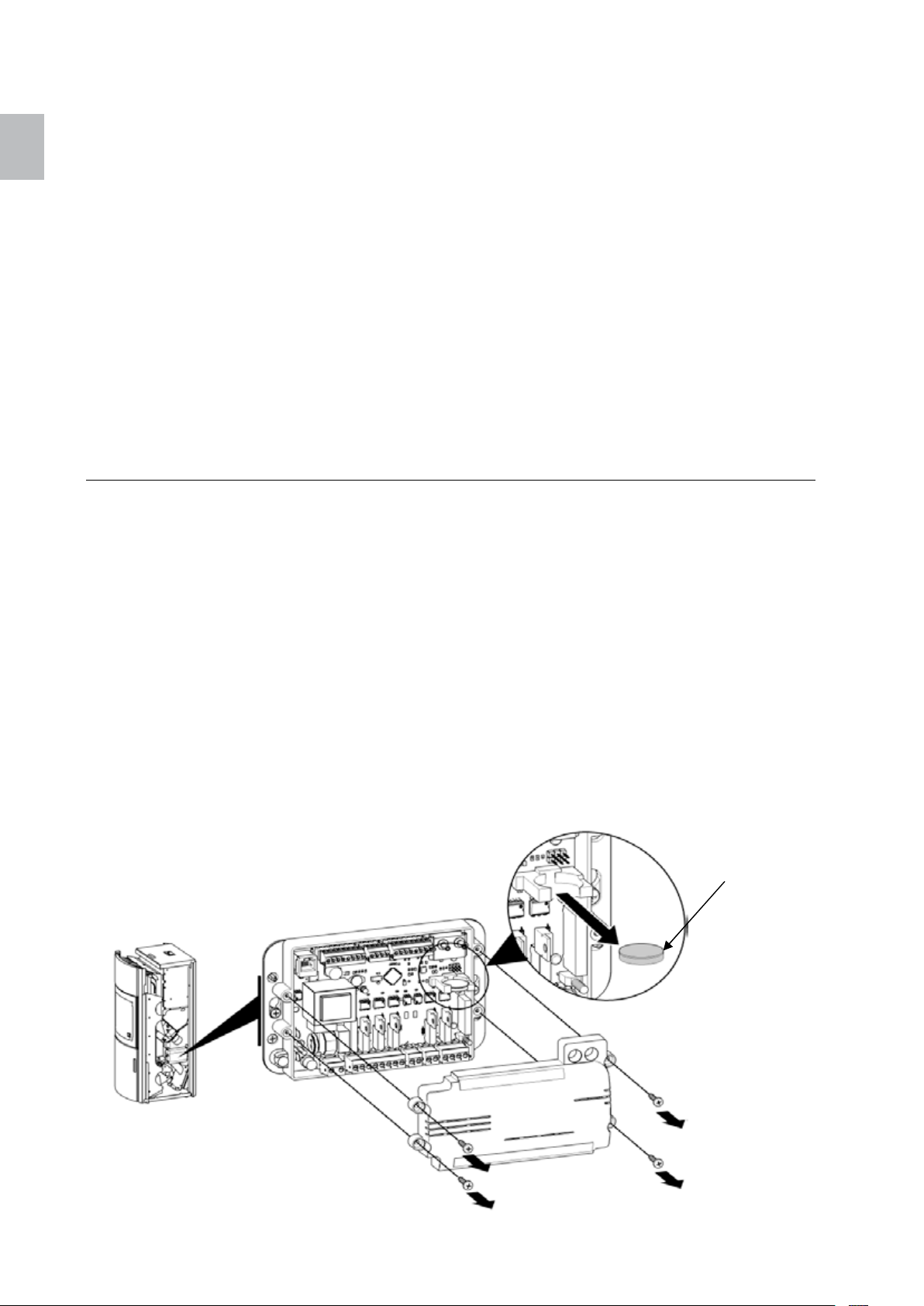
2. Die Batterie befindet sich auf der Leiterplatte (siehe Abbildung 3). Dazu ist zunächst die
Seitenverkleidung zu entfernen (siehe 13.1).
3. Entfernen Sie die alte Batterie mit einer ISOLIERTEN Zange oder einem ähnlichen Werkzeug
aus dem Halter. Achten Sie darauf, die Kontakte des Batteriehalters nicht zu verbiegen.
4. Setzen Sie die neue Batterie unter Beachtung der richtigen Polung ein (siehe Abbildung 3).
5. Schließen Sie die Netzstromversorgung wieder an.
Knopfbatterie
CR2032
Abbildung 3: Austauschen der Batterie
Page 13
Polly 11 deutsch
Anzeige
Code
Ursache
Lösung
6. Fehlerbehebung
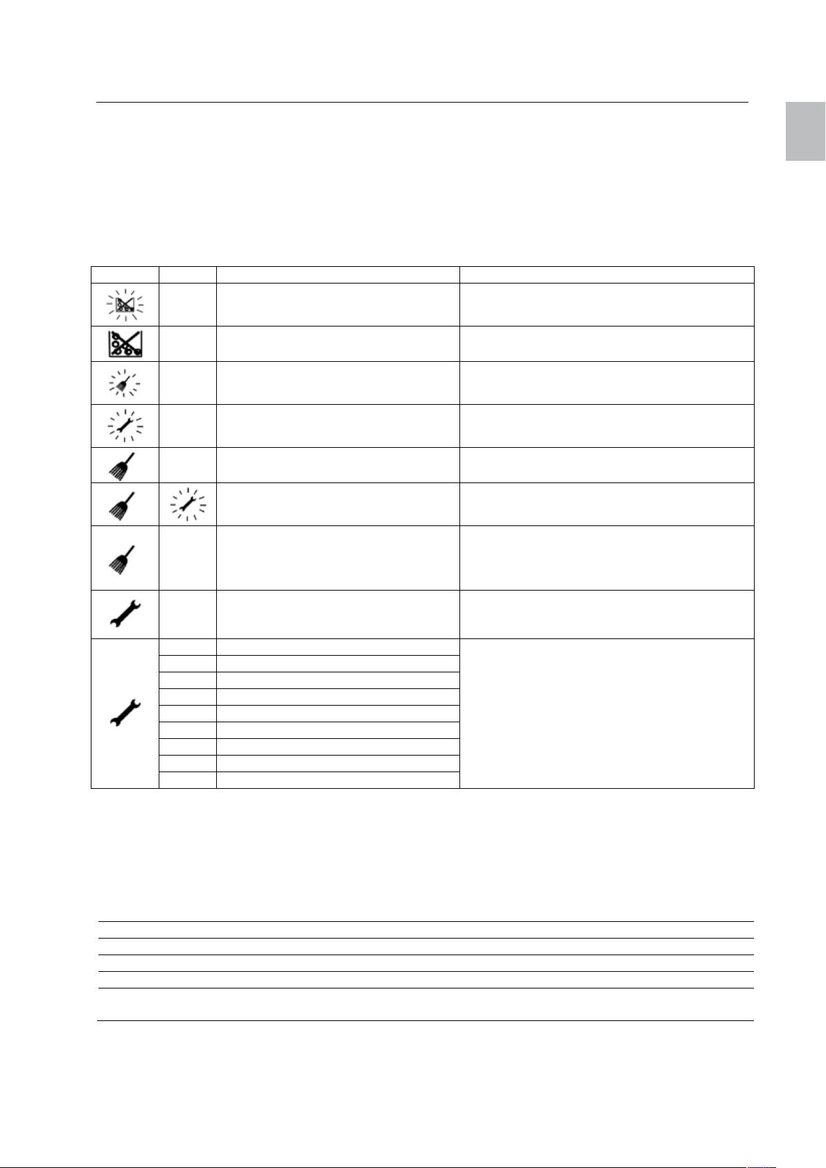
Das Bedienfeld gibt Benachrichtigungen und Warnungen für Alarme und Fehler aus, die bei der
Verwendung der Steuereinheit auftreten können. Die Anzeigesymbole zeigen ein Problem an. Bei einer
Alarmbenachrichtigung blinken die Symbole, bei Fehlern leuchten die Symbole durchgehend. Im Fall
eines Alarms ist die Feuerstätte noch funktionsfähig, im Fall eines Fehlers liegt eine schwere
Funktionsstörung der Feuerstätte vor und das Servicepersonal muss kontaktiert werden.
Jedem Alarm und jedem Fehler ist ein Code zugeordnet, anhand dessen das Problem identifiziert werden
kann. Um den Code anzuzeigen, halten Sie die Abbruchtaste gedrückt. Wenn kein Alarm-/Fehlercode
verfügbar ist, wird am Display "----" angezeigt.
A001 niedriger Brennstoffstand Brennstoff nachfüllen
---- kein Brennstoff Brennstoff nachfüllen
deutsch
A003
A004 Batterie ist schwach
---- Luftmengensensor ist verschmutzt
----
E109
E001 Fehler des Bedienfeldes
E004 Kommunikationsfehler Hauptplatine
E101 Übertemperatur im Brennraum
E107 Fehler Flammtemperaturfühler (TC2)
E108 Fehler Sicherheitstemperaturbegr.
E109 Fehler Druckschalter im Tankdeckel
E110 Fehler Raumfühler (NTC1)
E112 Übertemperatur Feuerraumfühler
E115 allgemeiner Fehler
Um die Fehlermeldung zu quittieren, die Ein-/Aus-Taste solange gedrückt halten, bis das Symbol erlischt.
Brennkammer oder Rauchzug ist
verschmutzt
Luftmengensensor ist defekt Luftmengensensor tauschen
Tür der Brennkammer offen,
Aschebox ist nicht eingesetzt,
Rost schließt nicht
Tankdeckel nicht vollständig
geschlossen,
Rost kann nicht schließen
Brennkammer kontrollieren und leeren,
Rauchabzug fegen lassen
Batterie austauschen
siehe Pkt. 5. Austauschen der Batterie
Luftmengensensor herausziehen und
Verschmutzung vom Messsensor abblasen
Tür der Brennkammer schließen,
Aschebox einsetzen,
Pellets zwischen Rost und Brenntopf,
Rostmotor überprüfen
evtl. eingeklemmte Pellets entfernen
Fehlercode notieren und Servicepersonal
kontaktieren
6.1. LED-Anzeigen an der Steuereinheit
Die Steuereinheit verfügt über zwei LED-Anzeigen, die Informationen zum Betrieb der Steuereinheit
liefern. In unten stehender Tabelle wird die Bedeutung der LED-Signale beschrieben:
Signal LED 2 LED 1
Funktion Überprüfung der Stromversorgung Überprüfung der Kommunikation
AUS Keine Stromversorgung Störung oder nicht programmiert
Leuchtet Stromversorgung in Ordnung –
Blinkt schnell
(5-mal pro Sekunde)
– Kommunikation in Ordnung
Page 14
deutsch
deutsch 12 Polly
6.2. Ausfall der Stromversorgung
Während eines Stromausfalls bleibt die Steuereinheit dank der internen Batterie weiter aktiv.
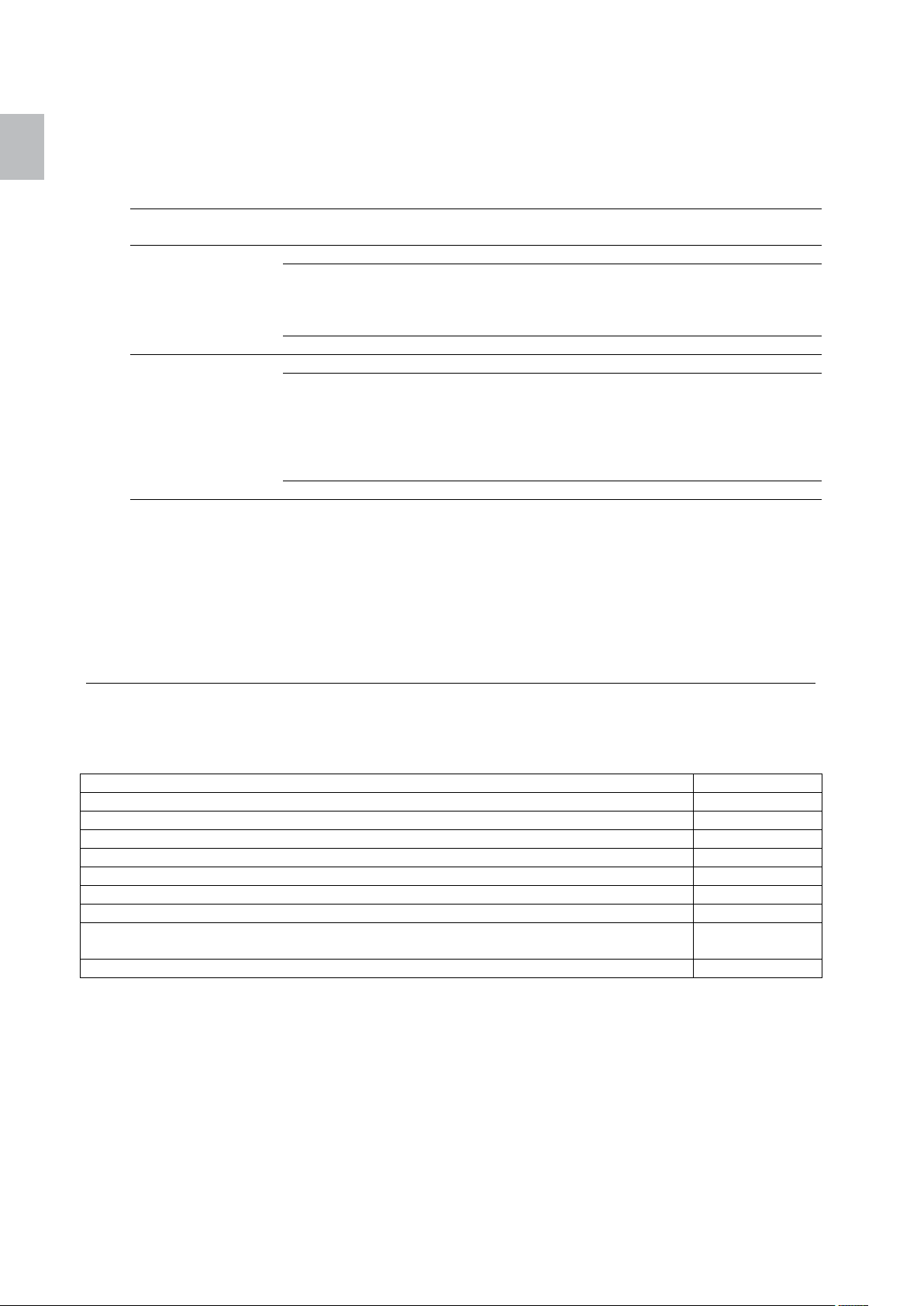
Im Fall eines Stromausfalls operiert die Steuereinheit wie folgt:
Dauer des
Stromausfalls
Weniger als 1
Minute
Mehr als 1 Minute Phase Fire up (Anheizen) Die Steuereinheit operiert normal weiter.
Betrieb vor dem
Stromausfall
Phase Fire up (Anheizen) Die Steuereinheit operiert normal weiter.
Phase Burning
(Verfeuerung)
OFF (Aus) OFF (Aus)
Phase Burning
(Verfeuerung)
OFF (Aus) OFF (Aus)
Betrieb nach dem Stromausfall
Die Steuereinheit prüft die Lufttemperatur und
operiert entweder weiter in der
Verfeuerungsphase oder startet in der
Anheizphase neu.
Die Steuereinheit prüft die Temperatur der
Rauchgase. Wenn die Rauchgastemperatur
unter den Wert von PAR56 abgefallen ist,
startet die Feuerstätte in der Anheizphase
neu, anderenfalls operiert sie weiter in der
Verfeuerungsphase.
6.3. Unbestimmte Fehler am Bedienfeld
Bestimmte in der Steuereinheit gespeicherte Informationen werden beim Starten am Bedienfeld
aktualisiert (zum Beispiel die Konfiguration).
Wenn an der Steuereinheit Änderungen vorgenommen werden und das Bedienfeld unerwartete Fehler
anzeigt, setzen Sie das Bedienfeld zurück, indem Sie es trennen und wieder anschließen. Wenn das
Problem weiterhin besteht, kontaktieren Sie das Servicepersonal.
7. Reinigung
Da die Reinigungsintervalle stark vom Aufstellungsort und den Betriebsstunden abhängig sind, gelten die
in der nachfolgenden Tabelle angeführten Zeitangaben nur als Richtwerte. Grundsätzlich müssen die
nachstehend angeführten Komponenten je nach Verschmutzungsgrad gereinigt werden.
Reinigung der Sichtscheibe 2-3 Tage
Sichtprüfung Brenntopf und Rost, anhaftende Ablagerung entfernen 2-3 Tage
Entleerung der Aschebox und Reinigung des Brennraumes 7-14 Tage
Tausch des Luftfilters 1-2 Monate
Reinigung der Rauchgaszüge, Rauchgassammler und Saugzuggebläse 1 x jährlich
Reinigung Brennraumtemperaturfühler (nur mit trockenem Tuch) 1 x jährlich
Reinigung Luftmengensensor (Abblasen des Meßdrahtes) 1 x jährlich
Tausch der Batterie 2 - 3 Jahre
Kontrolle aller Dichtungen (Tür, Aschebox, Rost, Tankdeckel); gegebenenfalls
ersetzen
Reinigung des Schornsteins lt. Schornsteinfegermeister min. 1 x jährlich
1 x jährlich
Page 15
Polly 13 deutsch
8. Konformitätserklärung
deutsch
9. Garantie
Für Ihren AUSTROFLAMM-Pelletofen garantieren wir für die einwandfreie Funktion des Korpus 6 Jahre,
aller weiteren Bauteile aus Stahl und Guss 2 Jahre ab dem Erstverkaufsdatum. Stahl- und Gussteile, die
während der Garantiezeit Material- und / oder Verarbeitungsmängel aufweisen, werden gegen Neuteile
ersetzt.
Wir gewähren keine Garantie auf Verschleißteile (z. B.: Keramott, Dichtungen, Bodenrost sowie alle
Elektro- und Elektronikbestandteile lt. Pkt. 11.2), Oberflächenbeschichtungen, Lack, Glas und Keramiken.
Voraussetzungen für unsere Garantieleistung sind:
1. Ihr AUSTROFLAMM-Pelletofen wurde gemäß dem Benutzerhandbuch betrieben und von einem
Fachmann installiert.
2. Der Garantieanspruch wird mit der vollständig ausgefüllten Garantiekarte und der Rechnung bei
einem AUSTROFLAMM-Fachhändler geltend gemacht.
WICHTIG: Unsere Garantieleistung umfasst die kostenlose Lieferung der Neuteile. Arbeits- und
Wegzeiten werden dadurch nicht umfasst. Eine ungerechtfertigte Garantieinanspruchnahme wird dem
Betreiber rückbelastet.
Page 16

français
Sommaire
1. Informations importantes ....................................................................................... 15
2. Combustible ........................................................................................................... 15
3. Dimensions et données techniques ....................................................................... 16
4. Utilisation du tableau de commandes .................................................................... 17
4.1. Tableau de commandes .................................................................................. 17
4.2. Structure du menu ........................................................................................... 19
4.3. Naviguer dans le menu .................................................................................... 20
4.4. Réglage de l’horloge ........................................................................................ 20
4.5. Réglage de la température .............................................................................. 20
4.6. Réglage de la puissance ................................................................................. 21
4.7. Réglage du programme hebdomadaire ........................................................... 21
4.8. Modification des options de l’équipement ........................................................ 22
5. Maintenance de l’unité de contrôle ........................................................................ 23
5.1. Changement de la batterie .............................................................................. 23
6. Dépannages .......................................................................................................... 24
6.1. Indications LED sur l’unité de contrôle ............................................................. 24
6.2. Défaillance de l’alimentation électrique ............................................................ 25
6.3. Erreur aléatoire sur le tableau de commande .................................................. 25
7. Nettoyage .............................................................................................................. 25
8. Déclaration de conformité ...................................................................................... 26
9. Garantie ................................................................................................................. 26
Schéma ......................................................................................................................... 53
Fonction / Composants – Description ........................................................................... 53
Eléments principaux du poêle ................................................................................... 53
Eléments électriques et électroniques ....................................................................... 54
Revêtement du foyer ................................................................................................. 55
Eléments de la porte ................................................................................................. 56
Plan électrique .............................................................................................................. 56
Montage sur l’appareil................................................................................................... 57
Montage et démontage de l’enveloppe et du couvercle ............................................ 57
Ajustement des charnières du haut ........................................................................... 58
Ajustement des charnières du bas ............................................................................ 59
Démontage de la paroi arrière ................................................................................... 60
Nettoyage du canal des gaz d’échappement, vidange du cendrier ........................... 61
Changer le filtre ......................................................................................................... 63
Changer la bague du brazero .................................................................................... 64
Page 17
Polly 15 français
IMPORTANT
:
1. Informations importantes
• Les informations contenues dans cette notice sont d’ordre général. Les normes et réglementations
nationales et européennes ainsi que les régles régionales de construction ou de sécurité au feu sont
à prendre en considération.
• Avant l’installation et l’utilisation de cet appareil, il est impératif de prendre connaissance de cette
notice. Conservez précieusement ce document à proximité du poêle pour pouvoir le consulter à tout
moment.
• Votre appareil ne peut être mis en service la premiére fois que par un spécialiste, conseillé par votre
fabricant.
• Respecter les instructions de cette notice vous garantit la sécurité des personnes, et permet le
maintien en bon état de fonctionnement ainsi qu’une durée de vie prolongée de votre appareil. Pour
la conception de cet appareil, les normes et les lignes directives indiquées au paragraphe 8 (Certificat
de conformité) ont été respectées.
• Pendant le temps de garantie, il est interdit de changer des composants ou de remplacer des
éléments qui ne seraient pas des originaux sous peine de voir le droit à la garantie s’annuler.
• Avant chaque intervention, débranchez l’alimentation électrique.
• Les schémas et autres dessins contenus dans cette notice ne sont qu’à titre explicatif. Le fabricant
poursuit une politique de développement continu et des modifications peuvent apparaître à tout
moment, sans avoir prévenu au préalable.
• Toutes les dimensions sont indiquées en mm.
• Votre appareil n’est pas destiné à servir d’échelle ni à être utilisé pour étendre linge ou objets.
• Les surfaces de votre appareil à pellets deviennent très chaudes pendant le fonctionnement, faites y
très attention. Nous vous conseillons d’utiliser le gant de protection. Prévenez vos enfants du danger
de brûlure et tenez les éloignés du poêle pendant son fonctionnement.
• Utilisez seulement du pellet (granulés) comme indiqué au paragraphe „combustible“.
• Ne déposez pas d’objets inflammables ou non résistants à la chaleur à proximité de l’appareil.
• Ne mettez pas de linge à sécher sur l’appareil. Les étendoirs à linge et autres doivent être installés à
une distance suffisante du poêle => risque d’incendie !
• Pendant le fonctionnement de votre appareil, la manipulation de matières inflammables ou explosives
est interdite à proximité.
• Vous devez vous assurer que l’alimentation en air est suffisante et que les gaz peuvent s’échapper
correctement.
• La grille de convection ne doit jamais être obstruée, même pas en partie.
• Les équipements d’aération se trouvant dans la même pièce que l’appareil peuvent être sources de
problèmes.
• Le poêle à pellets doit être, selon son degré de salissure, nettoyé régulièrement. (voir au paragraphe
7.5 le nettoyage de la chambre à gaz et au paragraphe 7.6 le changement du filtre).
• Les réparations ne peuvent être effectuées que par un spécialiste, conseillé par votre fabricant.
• Les pièces électriques et électroniques doivent être régulièrement vérifiées voire changées si
nécessaires (voir le chapitre 5.2)
français
2. Combustible
Le pellet, ou granulé, est un combustible qui est obtenu en pressant de la sciure de bois non traité, c’est
à dire sans peinture, sans colle ou autres.
Les différentes qualités de pellets, plus ou moins bonnes, peuvent provoquer pendant la phase de
combustion divers dépôts dans le brazéro ou sur la grille de l’appareil.
C’est pourquoi nous vous conseillons d’utiliser des pellets qui ne contiennent pas de liants chimiques et
dont la combustion ne laisse quasiment pas de résidus.
Le poêle a été homologué à la norme ÖN EN 14961 voire ENplus.
L’utilisation de pellets de mauvaise qualité ou autre matériau endommage les fonctions
de votre appareil et peut ainsi provoquer l’annulation de la garantie et la responsabilité
du fabricant ne peut être engagée.
En outre, l’appareil nécessite quelques cycles de chauffage pour s’adapter de façon
optimale à votre environnement.
Page 18
Données techniques
français
français 16 Polly
3. Dimensions et données techniques
Puissance de chauffe nominale 8,0 kW
Puissance de chauffe partielle 2,4 kW
Volume de la piéce 55 – 190 m³
Rendement > 90 %
Taux de CO en puissance nominale < 180 mg/Nm³
Taux de CO en puissance partielle 155 mg/Nm³
Température des gaz 150 °C
Débit des gaz en chauffe nominal 4,4 g/s
Débit des gaz en chauffe partielle 3,2 g/s
Volume du réservoir 26 kg / 40 l
Combustible Pellet
Consommation de pellets min./max env. 0,6 – 1,8 kg/h
Autonomie min./max env. 12 - 40 h
Ø de la buse de raccordement 80 mm
Ø de la buse des gaz 100 mm
Puissance électrique à l’allumage 300 W
Puissance électrique en fonctionnement 50 W
Tension / Fréquence électrique 230 V / 50 Hz
Variation de tensions : 0,9 - 1,1 de la tension nominale
Variation de fréquence : 0,99 - 1,011 de la fréquence
0,98 - 1,02 sur le court terme
Dimensions………………………………….… H=1100, B=526, T=498 mm
Poids …………………………......... 150 kg
Distances de sécurite minimum
A l’avant………………… 800 mm
Sur le côté…………… 150 mm
A l’arriére………………. 100 mm
nominale sur le long terme
Page 19
Polly 17 français
4. Utilisation du tableau de commandes
4.1. Tableau de commandes
français
Image 4: tableau de commandes
Remarque
Maintenez le tableau de commandes dans un état de propreté correcte pour optimiser la performance.
Des tâches sur les touches, comme de la graisse, peuvent enclencher un signal, comme si la touche
avait été enfoncée.
Le tableau de commandes tactile est conçu de façon intuitive. Sur le bord supérieur du tableau de
commandes se trouve les différentes indications pour les alarmes, le programmateur (minuteur) et les
menus.
Sur l’écran apparaissent les valeurs programmées dans l’option menu choisie. Les touches permettent
de naviguer dans le menu et de mettre l’unité de commande en marche. Vous trouverez une description
des touches dans le tableau 1 à la page 18.
Le tableau de commandes dispose en outre d’un bipeur qui envoie des signaux sonores. Les signaux
sonores possibles sont :
• Son aigu et court : s’entend lorsque vous naviguez dans le menu et lors de diverses
programmations.
• Son long et grave : sonne en cas d’action inappropriée (appuyé sur le mauvais bouton)
• Son long et aigu : en cas d’alarme, ce son programmé par l’utilisateur se déclenche en pleine
puissance.
Vous trouverez une description des alarmes et erreurs dans le chapitre „corrections des erreurs“ de la
page 24.
Page 20
français
français 18 Polly
Bouton
Tableau 1: Touches du tableau de commandes.
Description
Bouton marche / arrêt : mise en fonctionnement, ou
arrêt, de l’appareil. Appuyer une seconde sur le
bouton.
Les touches du menu (flêches) servent à naviguer
dans le premier niveau du menu. Le menu
programmé à ce moment apparait sur le bord
supérieur en montrant le symbole correspondant. Ces
touches servent aussi aux divers réglages.
Les touches de réglage (touches plus et moins)
servent à naviguer dans les sous-menus ainsi qu’á
augmenter ou à réduire les valeurs lorsque la valeur
clignote.
En appuyant sur ce bouton, on appelle le mode
réglage. Il sert également à confirmer une donnée
programmée ou bien pour choisir un autre menu.
Le bouton d’annulation sert à interrompre une
modification et à revenir au menu supérieur. Si on
appuie plus de trois secondes sur cette touche, on
voit apparaitre le dernier code erreur ou alarme.
Page 21
Polly 19 français
4.2. Structure du menu
français
Image 5: structure du menu
Page 22

français
français 20 Polly
4.3. Naviguer dans le menu
Grâce aux touches „fléche“ gauche et droite, vous pouvez naviguer dans le premier niveau de menu. Le
symbole pour le menu choisi clignote. A l’écran, le réglage pour le premier sous-menu apparait.
Avec les touches plus et moins vous pouvez aller naviguer dans le deuxiéme niveau de menu (le sousmenu) vers le haut et vers le bas. Dans le schéma ci-dessus c’est l’inverse, de telle sorte que l’on pourrait
croire que vous naviguez dans le menu du dessous alors que vous naviguez au dessus. Pour simplifier
la navigation dans le deuxiéme menu, le numéro du menu correspondant est indiqué entre parenthéses.
Pour modifier une donnée dans le menu, il faut appuyer sur la touche Enter. Ainsi le mode réglage pour
le symbole choisi est activé. La valeur indicative commence à clignoter. Modifiez la valeur à l’aide des
touches plus et moins. Avec les fléches gauche et droite vous pouvez aller pas à pas dans le mode
réglage. Appuyez enfin sur la touche Enter pour sauvegarder les nouvelles données et quitter le mode
réglage. Sur l’écran apparait alors le menu que vous venez de régler.
L’écran fait apparaitre soit la donnée programmée par vous soit la donnée réelle, selon le réglage. Par
exemple, pour le changement de la température, rentrez la température de la piéce désirée. Aprés avoir
quitté le mode réglage, l’écran va faire apparaitre la température réelle de la piéce (qui peut être
différente de celle de la température programmée).
Pour aller dans le troisiéme niveau de menu, appuyez sur la touche Enter. Vous pouvez alors naviguer
grâce aux touches plus et moins. La façon de modifier les données est la même que précédemment.
Pour quitter le mode réglage, sans sauvegarder les modifications, appuyez sur la touche annulation.
Grâce à ce bouton vous pouvez également retourner dans le haut du menu. Si par exemple vous êtes en
train de naviguer dans le programme 3 « weekly timer periods » (plages horaires hebdomadaires), vous
pouvez annuler les modifications et retourner au programme 3. En appuyant sur la touche annulation,
vous irez sur « weekly timer periods » (plages horaires hebdomadaires), puis sur « Clock » (horloge) et
enfin sur « Burning Power » (puissance de chauffe) dans le menu « Power » (puissance).
4.4. Réglage de l’horloge
Sur l’écran vous pouvez régler l’heure et la date.
Pour voir l’heure programmée, allez au menu « Time » (heure) en appuyant sur les touches du menu.
Vous verrez alors sur l’écran l’heure préalablement enregistrée.
Pour régler l’heure et la date, appuyez dans le menu « Time » sur la touche Enter. L’heure se met à
clignoter. Réglez l’heure grâce aux touches + ou -. Appuyez ensuite sur la touche menu à droite. Les
minutes se mettent à clignoter. Réglez les minutes à votre convenance. Appuyez alors sur la touche
menu de droite (flèche) et réglez la date de la même facon. La date apparait sous la forme année-moisjour. Appuyez sur le menu à droite et réglez le jour de la semaine. Choisissez le numéro correspondant
compris entre 1 (lundi) et 7 (dimanche). Confirmez le réglage de l’heure et de la date en appuyant sur la
touche Enter.
4.5. Réglage de la température
L’unité de contrôle propose deux possibilités pour régler la température de la piéce :
• Utilisation du programmateur hebdomadaire
• Réglage manuel de la température ou modification de la température de la piéce.
A l’aide du programmateur hebdomadaire, vous pouvez automatiser complétement votre appareil, de
sorte que vous n’ayez plus besoin d’agir, ou trés peu, sur le poêle.
Vous trouverez des informations précises à ce sujet au chapitre „réglage des programmes
hebdomadaires“ à la page 13.
Vous pouvez régler, voire modifier, la température de la piéce de facon manuelle. Si vous utilisez les
programmes hebdomadaires, vous pouvez mettre temporairement certains programmes hors service.
Page 23
Polly 21 français
Les réglages des programmes sont remis en service quand certaines conditions, fixées par l’horloge,
sont remplies à nouveau (par exemple lorsque l’horaire final est atteint et que l’appareil s’éteint).
Pour voir la température enregistrée pour la piéce, appuyez sur les touches menu dans le menu
„Temperature“ (température). Vous verrez alors à l’écran la température programmée de la piéce .
Pour régler la température que vous souhaitez, appuyez sur la touche Enter dans le menu
« Temperature » (température). Sur l’écran vous voyez apparaître en mode réglage la température
préalablement enregistrée (en clignotant). Vous pouvez augmenter ou baisser la température grâce aux
touches + ou -. Pour confirmer appuyez alors sur la touche Enter. Vous verrez apparaitre la nouvelle
température souhaitée.
4.6. Réglage de la puissance
L’unité de contrôle régle l’appareil de facon à assurer une puissance optimale. Vous pouvez mettre ces
réglages hors service et réduire ou augmenter la puissance de chauffe à votre guise et ainsi économiser
du combustible. Ces réglages influencent l’apport en combustible et la vitesse du ventilateur. Ainsi la
température de la piéce sera atteinte plus lentement et cela peut provoquer l’encrassement plus rapide
de la vitre.
Le réglage de la puissance de chauffe se fait par rapport à la puissance maximale utilisée par l’appareil
pour chauffer l’environnement. Quand la température imposée est atteinte, la puissance de chauffe est
automatiquement réduite.
Pour faire apparaître la puissance actuellement enregistrée, allez dans le menu „Power“ en appuyant sur
les touches du menu.
Pour atteindre la température souhaitée en réduisant la vitesse de chauffe, vous pouvez réduire la
puissance. Pour cela, enfoncez la touche Enter dans le menu « Power » (puissance). A l’écran vous
verrez apparaître la puissance de chauffe en mode réglage (ca clignote). Vous pouvez modifier cette
valeur avec les touches de réglage (puissance maxi, 4, 3, 2, 1 (puissance mini). Pour confirmer le tout,
appuyer enfin sur la touche Enter. A l’écran vous verrez alors apparaitre la puissance de chauffe
enregistrée.
français
4.7. Réglage du programme hebdomadaire
A l’aide de l’unité de contrôle, vous pouvez régler le programme hebdomadaire et ainsi automatiser le
fonctionnement de votre appareil. Il y a 6 plage horaires au choix, en sachant que vous pouvez
programmer par jour maximum 3 plages horaires différentes. Le programme définit le point de départ et
le point final ainsi que la température souhaitée. Pour régler votre programme,appelez le menu „Time“
(horaire) en appuyant sur les touches du menu. Choisissez ensuite en appuyant sur les touches de
réglage le chapitre « Weekly timer periods » (horaires hebdomadaires de démarrage). A l’écran vous
voyez apparaître la mention [ 3 ]. Appuyez sur la touche Enter pour choisir le programme 1 (Programm
1). A l’écran apparaît la mention [ P1 ]. Appuyez à nouveau sur la touche Enter pour passer en mode
réglage. L’heure pour le démarrage se met à clignoter. Réglez grâce aux touches réglage l’heure de
démarrage souhaitée. Appuyez alors sur la touche menu de droite. Les minutes se mettent à clignoter à
leur tour. Réglez les grâce aux touches traitement. Appuyez sur la touche menu de droite. Faites la
même chose avec l’horaire pour l’arrêt de l’appareil. Appuyez ensuite sur la touche menu de droite pour
choisir la température de la piéce pendant la plage horaire sélectionnée. Confirmez les réglages du
programme en appuyant sur la touche Enter. Reproduisez les réglages comme décrits ci-dessus pour
les autres programmes.
Exemple :
Programm 1 Programm 2 Programm 3 Programm 4 Programm 5 Programm 6
ON OFF ON OFF ON OFF ON OFF ON OFF ON OFF
5:30 07:30 08:00 11:30 12:00 23:00 17:00 23:00 20:00 22:30 04:00 07:00
16 °C 18 °C 19 °C 18 °C 17 °C 15 °C
Page 24
français
français 22 Polly
Pour régler les programmes pour tous les jours de la semaine, appelez le menu „Time“ (horaire) en
appuyant sur les touches du menu. Choisissez ensuite en appuyant sur les touches de réglage la
mention « Weekly timer days » (horaire hebdomadaire). Sur l’écran vous voyez apparaître [ 4 ]. Appuyez
sur la touche Enter et choisissez „Monday“ (lundi). Vous voyez apparaître [ d1 ]. Appuyez à nouveau sur
la touche Enter pour entrer dans le mode traitement du lundi. La valeur du programme 1. se met à
clignoter. Réglez grâce aux touches de réglage le programme désiré. Appuyez alors sur la flèche droite
du menu. La valeur pour le programme 2. se met à clignoter. Réglez le programme souhaité avec les
touches de réglage. Si vous ne souhaitez pas utiliser toutes les données du programme, appuyez alors à
l’aide de la touche « moins » sur [ OFF],.
Confirmez tous les réglages en appuyant sur la touche Enter. Répétez le processus ci-dessus pour tous
les jours de la semaine.
Exemple :
Pour activer ou désactiver la mise en marche de votre appareil avec les programmes hebdomadaires,
appelez le menu « Time » (horaire). Choisissez le programme « Weekly timer ON/OFF » (horloge
hebdomadaire on/off). Appuyez sur la touche Enter puis démarrez l’horloge (ON) ou éteignez la (OFF). Si
vous désactivez l’horloge hebdomadaire, vous pouvez configurer le fonctionnement de votre appareil de
facon manuelle.
4.8. Modification des options de l’équipement
Dans le menu „Setup“ (équipement) les options suivantes peuvent être réglées :
[ 1 ]… "Key lock" (blocage des touches)
[ 2 ]… "Idle display brightness" (luminosité de l’écran au repos)
[ 3 ]… "Idle display mode" (Ecran au repos)
[ 4 ]… "Beeper volume" (volume du beep) et
[ 6 ]… "Manual feed" (alimentation manuelle)
Avec l’option „Key lock“ (blocage des touches) vous pouvez bloquer les fonctions de l’écran de facon à ce
qu’aucune manipulation hasardeuse ne vienne modifier les programmes enregistrés. Quand cette option
est activée, vous pouvez naviguer dans le menu et voir les valeurs enregistrées mais vous ne pouvez pas
modifier les réglages, sauf celui du blocage des touches. Le réglage « Key lock » (blocage des touches)
propose les options suivante :
- OFF : le blocage des touches est désactivé, vous pouvez manipuler toutes les touches et modifier
ce que vous voulez
- Lo (faible) : le mode réglage est désactivé (la touche Enter est bloquée)
- Hi (haut) : le mode réglage et la fonction ON / OFF sont désactivés (les touches Enter et ON / OFF
sont bloquées)
Conseil
Nous conseillons d’activer le blocage des touches quand vous nettoyez votre appareil
Vous pouvez augmenter la luminosité de l’écran au repos ou bien la réduire pour faire des économies
d’énergie. Dés que vous touchez à l’écran, la luminosité passe en mode standard.
Le réglage « Idle display mode» (écran en repos) propose les options suivantes :
- OFF : l’écran reste dans le menu choisi. Si le mode réglage était actif, les modifications ne seront
pas prises en considération et le mode réglage sera annulé.
Page 25
Polly 23 français
-
+
- Option 1 : l’écran de fonctionnement quitte le menu actuel et indique en alternance la température
de la piéce désirée, l’autonomie du combustible et l’horaire. Si l’option « Fuel autonomy »
(autonomie du combustible) est sur OFF, alors cette option n’est pas montrée.
- Option 2 : l’écran de fonctionnement quitte le menu actuel et ouvre le menu « Temperature ».
L’écran montre la température actuellement enregistrée pour la piéce.
- Option 3 : l’écran de fonctionnement quitte le menu actuel et ouvre le menu « Clock » (horaire).
L’écran indique les horaires actuellement enregistrés.
- Option 4 : l’écran de fonctionnement quitte le menu actuel et ouvre le menu « Fuel autonomy »
(autonomie du combustible). Si cette option est sur OFF, l’écran de fonctionnement quitte ce menu
et ouvre le menu « Temperature ».
Le réglage du „Beeper Volume“ (volume du bip) régle le volume des signaux acoustiques de l’écran de
fonctionnement.
Avec l’option « Manual feed » (alimentation manuelle), l’alimentation en pellets peut être démarrée
manuellement. L’alimentation fonctionne pendant un court moment puis s’arrête. Avec cette option vous
pouvez nettoyer l’alimentation, la vider ou bien la remplir à nouveau.
Pour modifier l’option réglage, allez dans le menu « Setup » (réglage). Vous allez voir la valeur de la
luminosité de l’écran au repos que vous avez choisi. Vous pouvez à l’aide des touches deréglage faire
apparaître les différents réglages. Pour modifier un réglage, appuyez sur la touche Enter et augmentez
ou réduisez la valeur à l’aide des touches de réglage. Appuyez enfin sur la touche Enter pour confirmer.
5. Maintenance de l’unité de contrôle
français
5.1. Changement de la batterie
L’unité de contrôle passe sur la batterie interne en cas de coupure d’électricité. La batterie alimente
l’horloge interne et la mémoire du microprocesseur.
Quand la batterie est vide, l’unité de contrôle fonctionne normalement tant qu’elle est alimentée par une
source électrique. En cas de coupure d’électricité, l’horloge interne s’arrête et les phases de
fonctionnement ne sont pas enregistrées en mémoire. Quand l’électricité revient, l’horloge est remise à
zéro et l’unité de contrôle reste en phase OFF voire « Fire Up » (chauffer) (chaufferie)
Voici comment changer la batterie :
1. Coupez l’alimentation électrique
2. La batterie se trouve sur le circuit imprimé (voir image 3)
3. Retirez la batterie défectueuse de son support avec une pince ISOLANTE ou bien avec un outil
similaire. Faites attention à ne pas tordre le support pendant cette opération.
4. Reinstallez la nouvelle batterie en faisant attention aux pôles (voir image 3)
5. Vous pouvez reactiver l’alimentation électrique.
Bouton de batterie
CR2032
Image 6: changement de la batterie
Page 26
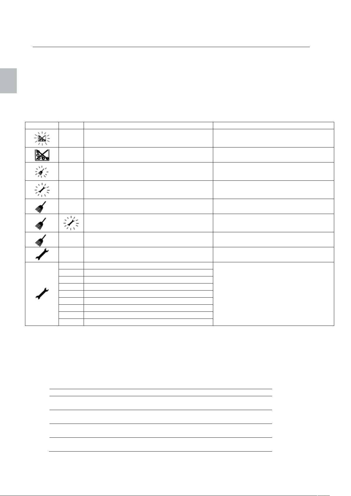
Affichage
Code
Cause
Solution
français
français 24 Polly
6. Dépannages
Le tableau de commande indique messages, avertissements et alarmes pour toute erreur qui pourrait
survenir lors de l’utilisation de l’unité de contrôle. Les symboles indiquent un problème. Lors d’une
alarme, les symboles se mettent à clignoter et lors d’une erreur, les symboles sont tout le temps allumés.
En cas d’alarme l’appareil continue de fonctionner, en cas d’erreur cela signifie qu’on est en présence
d’un dérangement sérieux de l’appareil et il faut alors avertir les services compétents. Pour chaque
alarme et pour chaque erreur, il existe un code qui permet d’identifier le problème.
Pour faire apparaître le code, appuyez longuement sur la touche „annulation“. Si aucun code alarme ou
erreur n’est disponible, l’écran affiche „---„.
A001 Niveau de combustible faible Remplir de combustible
---- Niveau de combustible épuisé
A003 Avaloir sale
A004 Batterie faible
---- Le capteur d’air est sale Enlever le capteur d’air et souffler dessus.
----
E109
E001 Erreur du tableau de commande
E004 Erreur de communication de la carte mére
E101 Température surélevée dans le foyer
E107 Erreur de la sonde de température (TC2)
E108 Erreur de température limite de sécurité
E109 Erreur sur le bouton du couvercle du réservoir
E110 Erreur du thermostat (NTC1)
E112 Température surélevée du thermostat
E115 Erreur générale
Pour quitter les affichages d’erreurs, appuyez aussi longtemps sur les touches Marche / Arrêt jusqu’á
disparition du symbole.
Le capteur d’air est défectueux Changer le capteur d’air
La porte du foyer est ouverte, le cendrier n’est
pas bien verrouillé
Le couvercle du réservoir est mal fermé
La grille ne peut pas se fermer
Remplir de combustible. Voir chapitre 6.7 :
réglage des options du combustible
Contrôler l’avaloir et le nettoyer, faire
ramoner le conduit
Changer la batterie. Voir chapitre 7.1 :
changement de la batterie
Refermer la porte correctement, remettre le
cendrier correctement.
Oter les pellets coincés dans le couvercle
ou la grille.
Noter le code affiché puis appeler les
services de maintenance.
6.1. Indications LED sur l’unité de contrôle
L’unité de contrôle dispose de deux affichages LED qui donnent des informations sur le fonctionnement
de l’unité de contrôle. Dans le tableau ci-dessous, nous vous donnons la signification des signaux LED :
Signal LED 2 LED 1
Fonction Vérication de l’alimention
électrique
Rien – aucun signal Pas d’alimentation
électrique
Allumé Alimention électrique
correcte
Clignote rapidement
(5 x par seconde)
– Communication
Vérification de la
communication
En dérangement ou
non programmé
–
correcte
Page 27

Polly 25 français
6.2. Défaillance de l’alimentation électrique
Pendant une coupure d’électricité, l’unité de contrôle reste active grâce à la batterie interne.
En cas de coupure électrique, l’unité de contrôle réagit de la facon suivante :
Durée de la
coupure
Moins d’une minute Phase „Fire up“
Plus d’une minute Phase Fire up (chauffage) L’unité de contrôle continue de fonctionner
Fonctionnement avant la
coupure
(chauffage)
Phase „Burning“ (mise en
feu)
OFF OFF (éteint)
Phase Burning (Mise à
feu)
OFF (Eteint) OFF (Eteint)
Fonctionnement aprés la coupure
L’unité de contrôle continue de fonctionner
normalement.
L’unité de contrôle vérifie la température de
l’air et soit continue la phase de mise en feu
soit démarre la phase de chauffe.
normalement.
L’unité de contrôle vérifie la température des
fumées. Si la température des fumées est
inférieure à la valeur PAR56, l’appareil
redémarre la phase de chauffage sinon elle
continue la phase de mise à feu.
français
6.3. Erreur aléatoire sur le tableau de commande
Lors du démarrage, certaines informations sauvegardées dans l’unité de contrôle sont actualisées sur le
tableau de commande (par exemple la configuration).
Si des modifications ont été apportées à l’unité de contrôle et que le tableau de commande affiche des
erreurs inattendues, remettre le tableau de commande en arriére en l’éteignant puis en le rallumant. Si le
probléme est toujours lá, il faut alors contacter le service de maintenance.
7. Nettoyage
Comme les fréquences de nettoyages dépendent fortement du lieu et de la fréquence d’utilisation de
l’appareil, les données notées ci-dessous ne sont que des indications. Ces composants doivent être
nettoyés selon leur degré de salissure.
Nettoyage de la vitre Tous les 2-3 jours
Vérification visuelle du brazéro, de la grille, dépôt éventuel. Tous les 2-3 jours
Vidange du cendrier et nettoyage du foyer Tous les 7-14 jours
Changement du filtre 1 à 2 fois par mois
Nettoyage du passage des fumées, de l’avaloir et ventilateur 1 fois par an
Nettoyage de la sonde de température du foyer 1 fois par an
Nettoyage du capteur d’air (en soufflant sur l’embout) 1 fois par an
Changement de la batterie 2-3 fois par an
Contrôle de tous les joints et les changer si nécessaire (porte, cendrier, grille, réservoir) 1 fois par an
Ramonage du conduit, au moins une fois par an
Page 28
français
français 26 Polly
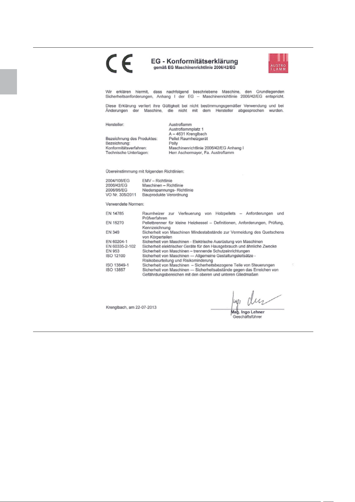
8. Déclaration de conformité
9. Garantie
Le corps de votre appareil à pellets Austroflamm est garanti 6 ans. Les autres piéces en acier ou en fonte
sont garanties 2 ans à compter de la date d’achat. Les piéces nécessitants une réparation seront
échangées contre des neuves.
Les piéces d’usure (Keramott, joints, grille ainsi que piéces électriques et électroniques indiquées au
chapitre 5.2), peinture, vitres, céramiques et autres surfaces ne sont pas comprises dans la garantie.
Conditions pour faire valoir la garantie :
1. Votre poêle à pellets AUSTROFLAMM est correctement utilisé et a été installé par un spécialiste.
2. Le droit à la garantie est valable seulement sous présentation de la carte de garantie
correctement remplie et de la facture d’achat par un concessionnaire AUSTROFLAMM.
Important : notre garantie ne comprend que la fourniture de piéces neuves. Les temps de travail et
de trajets ne sont pas compris dans cette garantie. En cas d’usage abusif du droit à la garantie, nous
exigerions le remboursement des frais engagés.
Page 29
Indice
1 Informazioni importanti per l'utente della stufa ....................................................... 28
2 Combustibile ........................................................................................................... 28
3 Dimensioni esterne e dati tecnici ............................................................................ 29
4 Uso del pannello comand ....................................................................................... 30
4.1 Pannello comandi ............................................................................................. 30
4.2 Configurazione del menu .................................................................................. 32
4.3 Navigazione nel menu ...................................................................................... 33
4.4 Impostazione dell'ora ........................................................................................ 33
4.5 Impostazione della temperatura ambiente ........................................................ 33
4.6 Impostazione della potenza di uscita ................................................................ 34
4.7 Impostazione delle programmazioni settimanali ............................................... 34
4.8 Modifica delle opzioni di setup .......................................................................... 35
5 Manutenzione della centralina ................................................................................ 36
5.1 Cambio della batteria ........................................................................................ 36
6 Eliminazione degli errori ......................................................................................... 36
6.1 Spie LED sulla centralina ................................................................................. 37
6.2 Interruzione dell'alimentazione elettrica ............................................................ 3 8
6.3 Errori indeterminati sul pannello comandi ......................................................... 38
7 Pulizia ..................................................................................................................... 38
8 Dichiarazione di conformità .................................................................................... 39
9 Garanzia ................................................................................................................. 39
Schema di funzionamento ............................................................................................. 53
Funzione/componenti – descrizione .............................................................................. 53
Componenti principali della stufa ............................................................................... 53
Componenti elettrici ed elettronici .............................................................................. 54
Rivestimento della camera di combustione ................................................................ 55
Elementi dello sportello .............................................................................................. 56
Schema elettrico ............................................................................................................ 56
Montaggio della stufa .................................................................................................... 57
Smontaggio/montaggio del rivestimento laterale e del coperchio .............................. 57
Regolazione della cerniera in alto .............................................................................. 58
Regolazione della cerniera in basso .......................................................................... 59
Smontaggio del pannello posteriore ........................................................................... 60
Pulizia del condotto dei fumi, svuotamento del cassetto raccoglicenere .................... 61
Cambio del filtro ......................................................................................................... 63
Sostituzione anello a inserimento braciere................................................................. 64
italiano
Page 30
AVVERTENZE:
italiano
italiano 28 Polly
1 Informazioni importanti per l'utente della stufa
• Le informazioni fornite nel presente manuale sono generiche. Devono essere osservate le norme
nazionali ed europee, le norme locali ed edilizie e le disposizioni antincendio.
• Le presenti istruzioni devono essere lette attentamente prima di installare, utilizzare o intervenire in
qualsiasi modo sulla stufa. Conservare accuratamente le istruzioni per l'uso e accertarsi che siano
poste sempre accanto alla stufa o comunque vicino alla stufa.
• L'osservanza delle disposizioni contenute nelle presenti istruzioni garantisce la sicurezza delle
persone e dell'apparecchio, oltre che un funzionamento economico e una lunga durata del prodotto.
Durante la progettazione e la costruzione della stufa è stato tenuto conto di tutte le norme e direttive
della
indicate al punto 8.
• Non è ammesso modificare i componenti o sostituirli con parti non originali, altrimenti con decorrenza
immediata non potranno più essere fatti valere i diritti di garanzia e l'omologazione non sarà più
valida.
• Prima di qualsiasi intervento staccare l'alimentazione elettrica della stufa.
• Gli schemi e i disegni compresi nella fornitura sono forniti solo a titolo illustrativo; il costruttore
sviluppa e aggiorna continuamente i suoi prodotti e può effettuare modifiche senza preavviso.
• Tutte le misure riportate nelle istruzioni per l'uso sono indicate in mm.
• ATTENZIONE: l'apparecchio deve essere messo in funzione esclusivamente da personale qualificato
istruito dal costruttore.
• La stufa non è adatta per essere utilizzata come scala o per fungere da impalcatura.
• Si tenga presente che la superficie della stufa a pellet mentre è in funzione può riscaldarsi
notevolmente. Per maneggiare la stufa a pellet utilizzare sempre il guanto protettivo. I bambini
devono essere istruiti in merito ai pericoli e devono essere tenuti lontani dalla stufa mentre è in
funzione.
• Utilizzare solo pellet come descritti al punto 2. Combustibile.
• È vietato posare oggetti non resistenti al calore sulla stufa o nelle sue vicinanze.
• Non stendere la biancheria sulla stufa per l'asciugatura. Anche gli stendibiancheria o altri prodotti
simili devono essere collocati a una distanza sufficiente dalla stufa Pericolo di incendio!
• Mentre la stufa è in funzione è vietato maneggiare sostanze facilmente infiammabili ed esplosive
nello stesso locale o nei locali adiacenti.
• Deve essere garantita un'alimentazione sufficiente di aria comburente e uno scarico sicuro dei fumi.
Controllare sempre che il comignolo non sia intasato, soprattutto dopo un periodo prolungato di
inattività della stufa.
• La griglia per lo scambio termico non deve essere mai chiusa, neanche parzialmente.
• I dispositivi di aerazione messi in funzione insieme alla stufa nello stesso locale o in locali collegati
possono creare problemi.
• La stufa a pellet deve essere pulita regolarmente in funzione del grado di sporcizia (vedere il punto 7.
Pulizia, 13.5 pulizia del condotto dei fumi e 13.6 cambio del filtro).
• Le riparazioni della stufa a pellet devono essere eseguite esclusivamente da personale qualificato
istruito dal costruttore.
• Sostituire le parti in funzione del fabbisogno e dello stato delle parti. Controllare regolarmente che i
componenti elettrici ed elettronici siano esenti da danneggiamenti o segni di usura (vedere anche il
punto 11.2 Componenti elettrici ed elettronici)
• I dispositivi di sicurezza non devono essere bypassati.
dichiarazione di conformità.
2 Combustibile
Il pellet è un combustibile ottenuto mediante pressatura della segatura ricavata da legni non trattati,
ovvero senza vernici, colle o sostanze analoghe.
Le "incrostazioni" prodotte dai pellet durante la fase di combustione nel braciere e sulla griglia della stufa
variano in funzione della qualità dei pellet. È consigliato l'utilizzo di pellet non contenenti leganti chimici e
che lasciano il minimo residuo. Il funzionamento della stufa è stato verificato con pellet a norma ÖN EN
14961-2 o ENplus.
L'utilizzo di pellet di qualità scadente o di altro materiale danneggia la funzionalità della
stufa e può comportare il decadimento della garanzia oltre ad esonerare il costruttore dalle
responsabilità connesse.
È necessario inoltre eseguire alcuni cicli di combustione per consentire alla centralina della
stufa di conformarsi in modo ottimale alle condizioni ambiente.
Page 31
Polly 29 italiano
3 Dimensioni esterne e dati tecnici
italiano
Resa calorica nominale (NWL) 8 kW
Resa calorica a carico parziale 2,4 kW
Volume riscaldabile 55 – 190 m³
Rendimento di combustione >90 %
Contenuto di monossido di carbonio con valore nominal <180 mg/Nm³
Contenuto di monossido di carbonio a carico parziale <155 mg/Nm³
Temperatura dei fumi con resa calorica nominale 150 °C
Portata massima dei fumi con resa calorica nominale 4,4 g/s
Portata massima dei fumi a carico parziale 3,2 g/s
Capacità del serbatoio 26 kg / 40 l
Combustibile Pellet
Consumo pellet min/max 0,6 – 1,8 kg/h
Autonomia min/max circa 12 - 40 h
Bocchetta aria Ø 80 mm
Raccordo fumi Ø 100 mm
Amperaggio all'accensione 300 W
Amperaggio in corso di funzionamento 50 W
Tensione / Frequenza corrente 230 V / 50 Hz
Variazioni di tensione 0,9 - 1,1 della tensione nominale
Variazione di frequenza 0,99 - 1,01 della frequenza nominale permanent
0,98 - 1,02 breve
Dimensioni A x L x P 1100 x 526 x 498 mm
Peso 150 kg
Distanza minima laterale 150 mm
posteriore 100 mm
anteriore 800 mm
Limite di temperatura 0 - 40 °C
Umidità relativa dell'aria non condensante
Luogo di installazione Livello del mare < 1000 m
Page 32
italiano
italiano 30 Polly
4 Uso del pannello comand
4.1 Pannello comandi
Figura 7: Pannello comandi
Avvertenza
Per assicurare una prestazione ottimale tenere il pannello comandi sempre pulito. Le macchie sui tasti,
ad esempio di grasso, possono far scattare un segnale di attivazione del tasto.
Il pannello comandi tattile è intuitivo. Lungo il bordo superiore sono disposte le spie di alcuni allarmi, della
programmazione oraria e dei menu.
Sul display vengono visualizzati i valori impostati o correnti per l'opzione di menu attualmente
selezionata. I tasti consentono di navigare nel menu e di gestire il funzionamento della centralina. Una
descrizione dei tasti si trova in
Tabelle 1: Tasten des Bedienfelds a pagina 31.
Il pannello comandi è dotato inoltre di un bip per i segnali di feedback del pannello. Sono possibili i
seguenti segnali acustici:
• Un suono acuto breve: viene emesso durante la navigazione nel menu e la modifica delle
impostazioni.
• Un suono grave lungo: viene emesso in caso di azione non ammessa (quando viene premuto un
tasto sbagliato)
• Un suono acuto lungo: in caso di allarme questo suono viene emesso con il volume impostato
dall'utente, in caso di errore invece emesso viene a volume pieno.
Per la descrizione degli allarmi e degli errori consultare il capitolo Fehlerbehebung a pagina 36.
Page 33
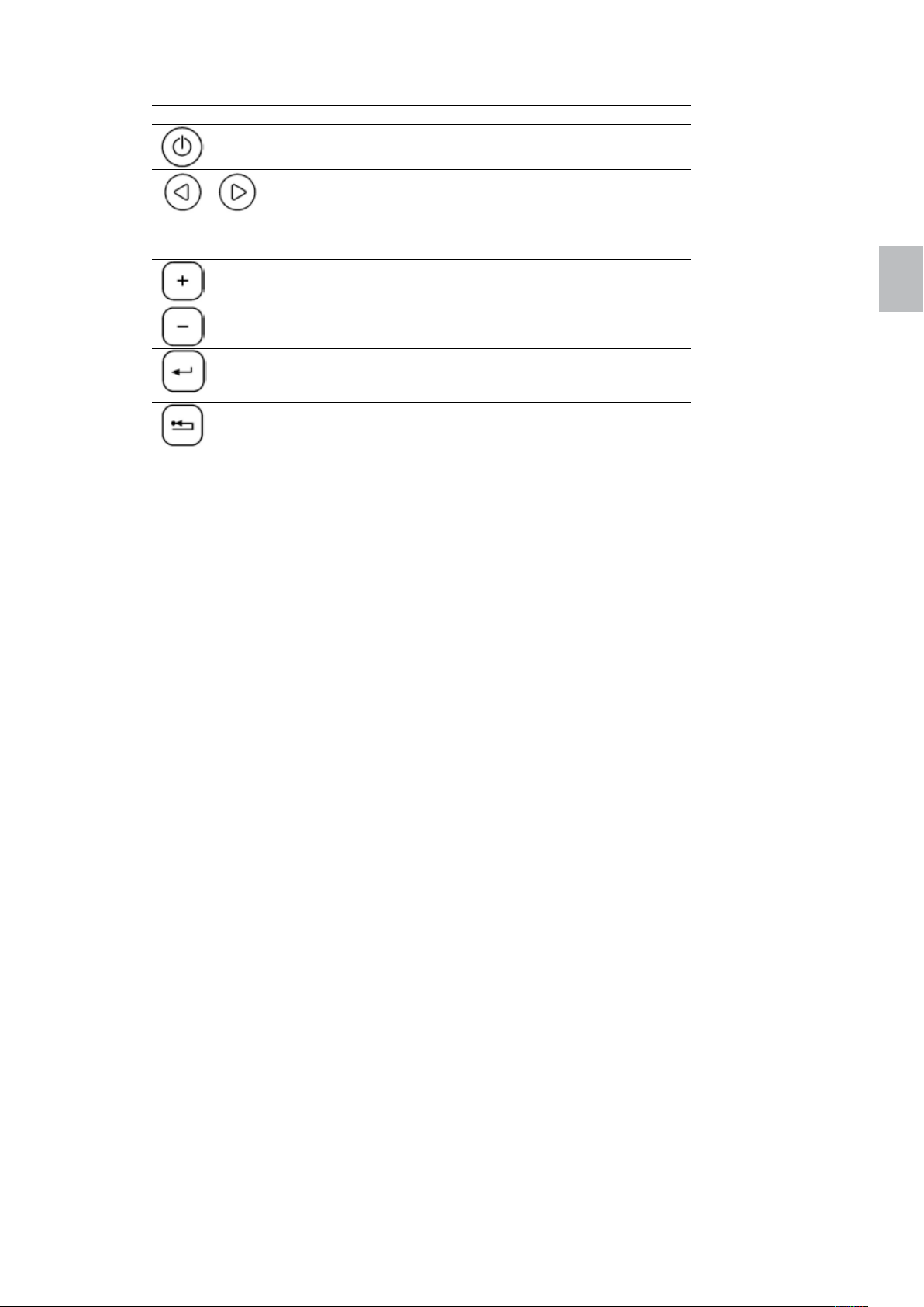
Polly 31 italiano
Tasto Descrizione
Il tasto ON/OFF consente di accendere o spegnere la
stufa. Premere il tasto per 1 secondo.
I tasti del menu (tasti freccia) consentono di navigare
Tabella 2: Tasti del pannello comandi
nel primo livello del menu. Il menu correntemente
selezionato è indicato dal simbolo corrispondente
lungo il bordo superiore. Questi tasti si utilizzano
anche nella modalità di modifica.
I tasti di modifica (tasti più e meno) consentono di
navigare nei sottomenu e di aumentare o ridurre i
valori in modalità di modifica quando il valore
selezionato è lampeggiante.
Il tasto Invio consente di richiamare la modalità di
modifica. Consente inoltre di confermare i valori
impostati o di selezionare altri sottomenu.
Il tasto Cancella consente di annullare le modifiche e
di ritornare al livello di menu superiore successivo.
Premendo questo tasto per oltre 3 secondi viene
visualizzato l'ultimo codice di errore o di allarme.
italiano
Page 34
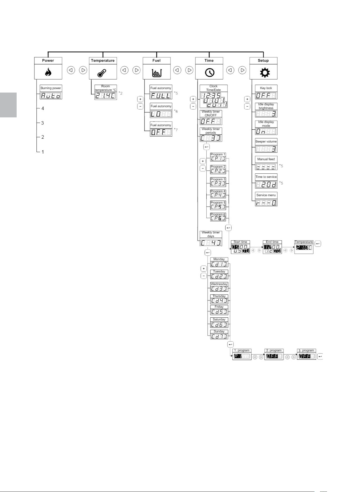
italiano
italiano 32 Polly
4.2 Configurazione del menu
Figura 8: Configurazione del menu
Page 35

Polly 33 italiano
4.3 Navigazione nel menu
Con i tasti freccia sinistro e destro è possibile navigare nel primo livello del menu. Si accende il simbolo
del menu selezionato. Sul display viene visualizzata l'impostazione della prima voce del sottomenu.
Con i tasti più e meno è possibile navigare verso l'alto e verso il basso nel secondo livello del menu (nel
sottomenu). La configurazione del menu rappresentata nella Figura 2 è rovesciata, perciò sembra che
l'utente nel menu si muova verso il basso, mentre in realtà si sta muovendo verso l'alto. Per semplificare
la navigazione nel secondo livello del menu, il numero della voce di menu corrispondente viene mostrato
brevemente tra parentesi.
Per modificare una impostazione nel menu premere il tasto Invio. Si attiva così la modalità di modifica per
l'impostazione selezionata. Il valore visualizzato inizia a lampeggiare. Modificare il valore con i tasti più e
meno. Con i tasti freccia sinistro e destro è possibile scorrere attraverso le opzioni della modalità di
modifica. Al termine premere il tasto Invio per salvare l'impostazione e uscire dalla modalità di modifica.
Sul display comparirà di nuovo la voce di menu che è stata modificata.
A seconda della impostazione sul display viene visualizzato o il valore impostato o il valore reale. Ad
esempio in caso di modifica della temperatura inserire la temperatura ambiente desiderata. Dopo l'uscita
dalla modalità di modifica sul display verrà visualizzata la temperatura reale (che può differire dalla
temperatura impostata).
Per richiamare il terzo livello di menu premere il tasto Invio. Con i tasti più e meno è quindi possibile
passare da una voce di menu all'altra. La procedura di modifica delle impostazioni è identica a quella
utilizzata nel secondo livello di menu.
Per uscire dalla modalità di modifica senza salvare le modifiche premere il tasto Annulla. Questo tasto
consente anche di ritornare indietro di un livello nel menu. Se si sta modificando ad esempio il
Programma 3 nella voce di menu "Weekly Timer Periods" (Programmazioni settimanali), con il tasto
Annulla è possibile annullare le modifiche e ritornare al Programma 3. Il tasto Annulla consente di arrivare
a "Weekly Timer Periods" (Programmazioni settimanali), poi a "Clock" (ora) e infine a "Burning Power"
(Potenza termica) nel menu "Power" (Potenza).
italiano
4.4 Impostazione dell'ora
Sul pannello comandi è possibile impostare l'ora e la data correnti. Per visualizzare l'ora corrente
premere il tasto del menu per passare al menu „Time“ (Ora). Sul display viene visualizzata l'ora corrente.
Per impostare l'ora e la data premere nel menu "Time" (Ora) il tasto Invio. L'ora lampeggia. Impostare
l'ora desiderata con i tasti di modifica. Premere quindi il tasto del menu destro. I minuti lampeggiano.
Impostare i minuti desiderati. Premere il tasto destro del menu e impostare la data con la stessa
procedura. La data viene emessa nel formato gg.mm.aaaa. Premere quindi il tasto destro del menu e
impostare il giorno della settimana. Selezionare il numero corrispondente tra 1 (lunedì) e 7 (domenica).
Confermare l'impostazione dell'ora e della data premendo il tasto Invio.
4.5 Impostazione della temperatura ambiente
La centralina offre due opzioni per impostare la temperatura ambiente. Sono le seguenti:
- Utilizzo delle programmazioni settimanali
- Impostazione manuale o modifica della temperatura ambiente
Le programmazioni settimanali consentono di automatizzare completamente il funzionamento della stufa
in modo da ridurre al minimo o eliminare completamente gli interventi dell'utente. Per informazioni più
dettagliate consultare il capitolo Einstellen der Wochenschaltprogramme a pagina 8.
La temperatura ambiente può essere impostata o modificata anche manualmente. In caso di utilizzo delle
programmazioni settimanali, è possibile sospendere temporaneamente le impostazioni del programma.
Le impostazioni del programma vengono annullate quando le condizioni definite per il timer sono
soddisfatte (al raggiungimento ad esempio dell'ora finale impostata e la stufa si spegne)
Page 36
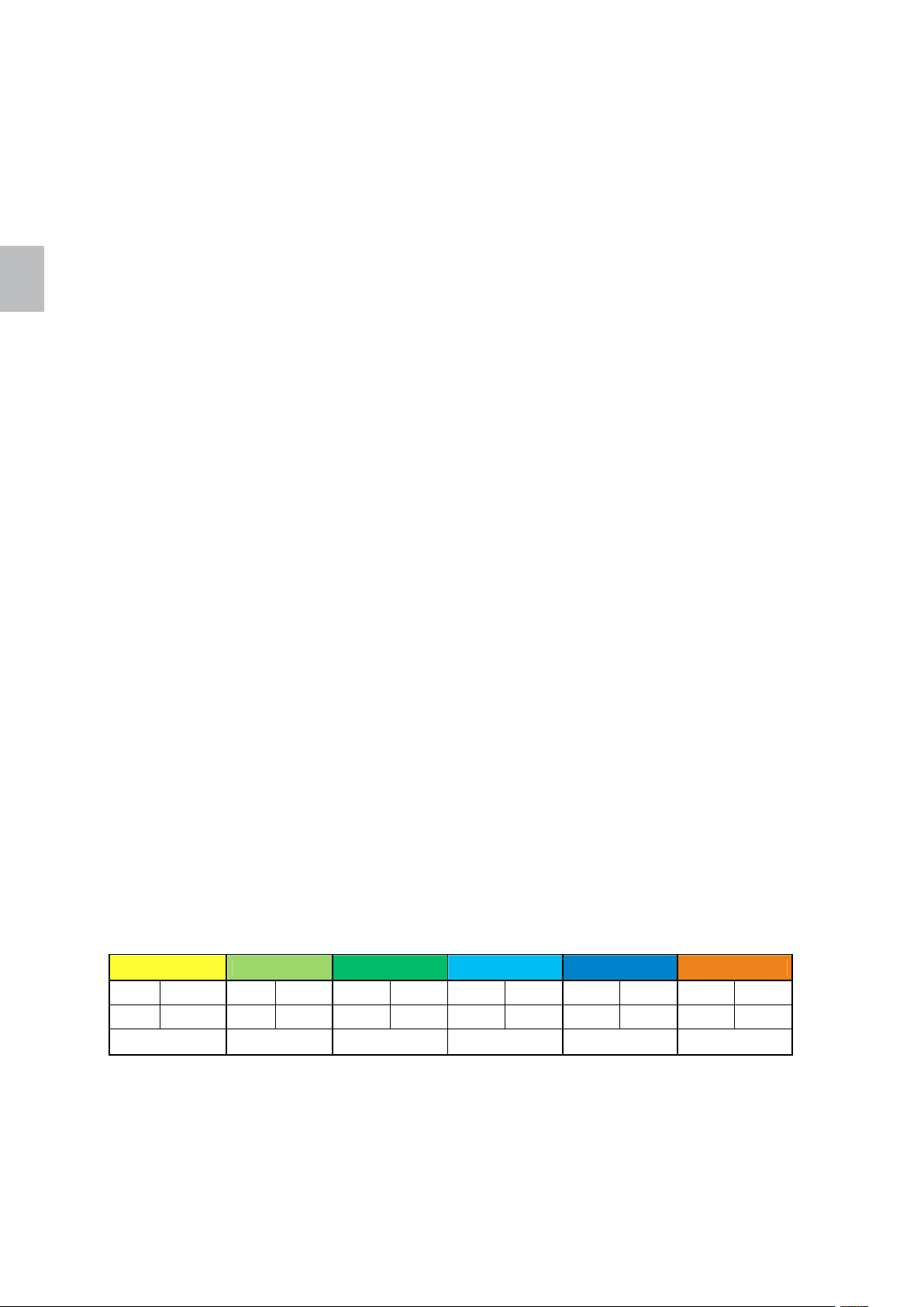
italiano
italiano 34 Polly
Per visualizzare la temperatura ambiente corrente premere il tasto del menu per passare al menu
"Temperature“ (Temperatura). Sul display viene visualizzata la temperatura ambiente corrente.
Per impostare la temperatura ambiente desiderata premere nel menu "Temperature" (Temperatura) il
tasto Invio. Sul display la temperatura di riferimento impostata viene visualizzata in modalità di modifica (il
valore lampeggia). Con i tasti di modifica è possibile aumentare o ridurre questo valore. Premere infine il
tasto Invio per confermare la temperatura impostata. Sul display viene visualizzata la temperatura
ambiente corrente.
4.6 Impostazione della potenza di uscita
La centralina regola la stufa in modo da assicurare una potenza ottimale. È possibile sospendere tali
impostazioni e ridurre la potenza termica per risparmiare combustibile. Queste impostazioni influiscono
sull'alimentazione del combustibile e sulla velocità delle ventole. La temperatura ambiente desiderata
verrà raggiunta più lentamente, pertanto i vetri della stufa possono sporcarsi prima.
L'impostazione della potenza termica si riferisce alla potenza termica massima utilizzata dalla stufa per
riscaldare l'ambiente. Al raggiungimento della temperatura di riferimento impostata la potenza termica
viene automaticamente abbassata.
Per visualizzare la potenza termica corrente premere il tasto del menu per passare al menu "Power“
(Potenza). Sul display viene visualizzata la potenza termica corrente.
Per rallentare il riscaldamento fino alla temperatura ambiente desiderata abbassare l'impostazione della
potenza termica. Premere nel menu "Power" (Potenza) il tasto Invio. Sul display la potenza termica viene
visualizzata in modalità di modifica (il valore lampeggia). Questo valore si può impostare con i tasti di
modifica in un range da automatico (potenza massima), 4, 3, 2 a 1 (potenza minima). Premere infine il
tasto Invio per confermare la potenza termica impostata. Sul display viene visualizzata la potenza termica
corrente.
4.7 Impostazione delle programmazioni settimanali
La centralina consente di impostare le programmazioni settimanali per automatizzare il funzionamento
della stufa. Sono disponibili sei programmi e per ogni giorno della settimana si possono selezionare al
massimo tre programmi. Il programma definisce l'ora iniziale e finale e la temperatura desiderata.
Per impostare un programma richiamare con il tasto del menu il menu "Time" (Ora). Premendo il tasto di
modifica selezionare quindi la voce "Weekly timer periods" (Programmazioni settimanali). Sul display
viene visualizzato [ 3 ]. Premere il tasto Invio per selezionare "Program 1" (Programma 1). Sul display
viene visualizzato [ P1 ]. Premere di nuovo il tasto Invio per passare alla modalità di modifica del
programma 1. L'ora iniziale lampeggia. Impostare l'ora iniziale desiderata con i tasti di modifica. Premere
quindi il tasto del menu destro. I minuti dell'ora iniziale lampeggiano. Impostare i minuti desiderati per
l'ora iniziale. Premere il tasto destro del menu e impostare l'ora finale. Premere quindi il tasto destro del
mouse per impostare la temperatura ambiente desiderata per l'arco di tempo selezionato. Confermare le
impostazioni del programma premendo il tasto Invio. Per impostare gli altri programmi ripetere i passi
sopra descritti.
Esempio:
Programma 1 Programma 2 Programma 3 Programma 4 Programma 5 Programma 6
ON OFF ON OFF ON OFF ON OFF ON OFF ON OFF
5.30 7.30 8.00 11.30 12.00 23.00 17.00 23.00 20.00 22.30 4.00 7.00
16 °C 18 °C 19 °C 18 °C 17 °C 15 °C
Per assegnare i programmi ai giorni della settimana premere il tasto del menu per richiamare il menu
"Time" (Ora). Premere quindi il tasto di modifica per selezionare la voce "Weekly timer periods"
(Programmazioni dei giorni della settimana). Sul display viene visualizzato [ 4 ]. Premere il tasto Invio per
selezionare "Monday" (lunedì). Sul display viene visualizzato [ d1 ]. Premere di nuovo il tasto Invio per
passare alla modalità di modifica per lunedì. Il valore per il 1° programma lampeggia. Impostare il
programma desiderato con i tasti di modifica. Premere quindi il tasto del menu destro. Il valore per il
Page 37
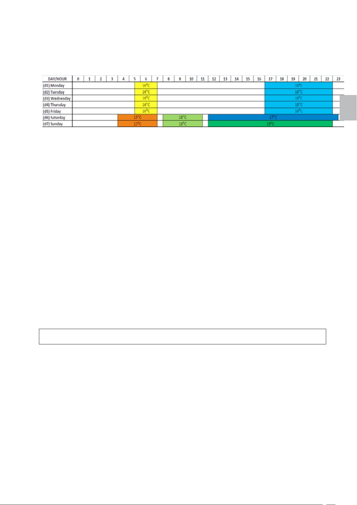
Polly 35 italiano
2° programma lampeggia. Impostare il programma desiderato. Qualora non si desideri occupare tutte le
destinazioni di programmazione, effettuare l'impostazione con il tasto meno su [ OFF ]. Confermare le
impostazioni del programma con il tasto Invio. Per impostare i programmi per tutti i giorni della settimana
ripetere i passi sopra descritti.
Esempio:
Per attivare o disattivare il funzionamento della stufa con le programmazioni settimanali premere il tasto
del menu per richiamare il menu Time (Ora). Premere quindi il tasto di modifica per selezionare la voce
"Weekly timer ON/OFF" (Timer settimanale on/off). Premere il tasto Invio e attivare (ON) o disattivare
(OFF) il timer settimanale. Con la disattivazione del timer settimanale il funzionamento della stufa deve
essere configurato manualmente.
4.8 Modifica delle opzioni di setup
Nel menu "Setup" (Setup) è possibile impostare le opzioni per:
[ 1 ]… "Key lock" (Blocco tasti)
[ 2 ]… "Idle display brightness" (Luminosità del display nello stato di riposo)
[ 3 ]… "Idle display mode" (Stato di riposo del display)
[ 4 ]… "Beeper volume" (Volume del bip) e
[ 6 ]… "Manual feed" (Alimentazione manuale)
.
Con l'opzione "Key lock" (Blocco tasti) è possibile bloccare il pannello comandi in modo da prevenire
qualsiasi modifica accidentale delle impostazioni. Con il blocco tasti attivato è possibile navigare nel
menu e visualizzare i valori correnti, ma non è possibile modificare le impostazioni, ad eccezione del
blocco tasti stesso. L'impostazione Key lock (Blocco tasti) offre le seguenti opzioni:
- OFF (disattivato): il blocco tasti è disattivato, tutti i tasti sono azionabili.
- Lo (basso): la modalità di modifica è disattivata (il tasto Invio è bloccato).
- Hi (alto): la modalità di modifica e la funzione di attivazione e disattivazione sono disattivati (il
tasto Invio e i tasti On/Off sono bloccati).
Suggerimento!
Consigliamo di attivare il blocco tasti per la pulizia del pannello comandi.
La luminosità del display può essere aumentata o ridotta nello stato di riposo per risparmiare energia.
Non appena il pannello comandi viene toccato, la luminosità del display aumenta fino al valore standard.
L'impostazione "Idle display mode" (Stato di riposo del display) offre le seguenti opzioni:
- OFF (disattivato): il pannello comandi rimane nel menu selezionato. Se la modalità di modifica
era attiva, le modificazioni vengono annullate e il pannello esce dalla modalità di modifica.
- Opzione 1: il pannello comandi esce dal menu corrente e alternativamente visualizza la
temperatura ambiente corrente e l'ora.
- Opzione 2: il pannello comandi esce dal menu corrente e apre il menu "Temperature"
(Temperatura). Sul display viene visualizzata la temperatura ambiente corrente.
- Opzione 3: il pannello comandi esce dal menu corrente e apre il menu "Clock" (Orologio). Sul
display viene visualizzata l'ora corrente.
L'impostazione "Beeper volume" (Volume del bip) controlla il volume del segnale acustico del pannello
comandi.
italiano
Page 38
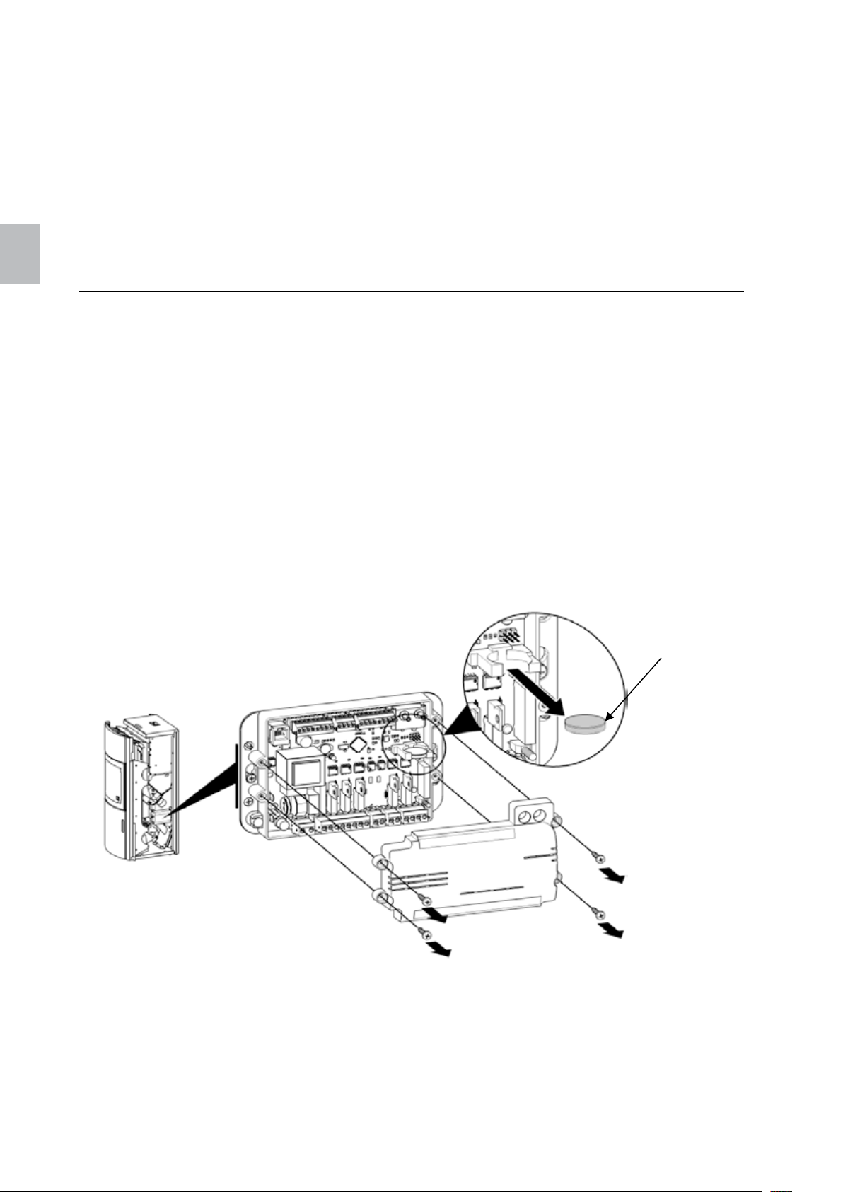
italiano
italiano 36 Polly
Con l'opzione "Manual feed" (Alimentazione manuale) è possibile avviare l'alimentazione manuale dei
pellet. L'alimentazione entrerà brevemente in funzione per poi arrestarsi. Questa opzione consente di
pulire o svuotare oppure riempire nuovamente l'alimentazione.
Per visualizzare le impostazioni di setup premere il tasto del menu per passare al menu "Setup“ (setup).
Viene visualizzata la luminosità del display nello stato di riposo. I tasti di modifica consentono di
visualizzare le impostazioni delle singole opzioni di setup. Per modificare un'impostazione premere il
tasto Invio e aumentare o ridurre il valore mediante i tasti di modifica. Premere infine il tasto Invio per
confermare il valore impostato.
5 Manutenzione della centralina
5.1 Cambio della batteria
In caso di mancanza di corrente o disinserimento dal cavo di rete la centralina commuta
sull'alimentazione a batteria. La batteria alimenta l'orologio interno e la memoria interna del
microprocessore.
In caso di batteria scarica, la centralina funzionerà normalmente finché è collegata al cavo di
alimentazione. In caso di mancanza di corrente l'orologio interno si ferma e la fase di funzionamento non
viene salvata in memoria. Dopo il ripristino dell'alimentazione l'ora viene resettata e la centralina resta in
fase OFF (disattivato) (modalità stufa) o "Fire up" (fase di riscaldamento) (modalità caldaia).
Come cambiare la batteria:
6. staccare il cavo di alimentazione.
7. La batteria è situata sulla scheda (vedere Abbildung 3). Per prima cosa occorre rimuovere il
rivestimento laterale (vedere 13.1).
8. Rimuovere la batteria usata dal portabatteria utilizzando una pinza ISOLATA o un utensile
analogo. Attenzione a non piegare i contatti del portabatteria.
9. Inserire la nuova batteria con i poli in posizione corretta (vedere Abbildung 3).
10. Collegare di nuovo il cavo di rete.
Batteria a
bottone
Figura 9: Cambio della batteria
6 Eliminazione degli errori
Il pannello comandi fornisce messaggi e avvisi per gli allarmi e gli errori che possono verificarsi durante
l'utilizzo della centralina. Le spie indicano la presenza di un problema. In caso di messaggio di allarme i
simboli lampeggiano, in caso di errore i simboli sono accesi fissi. L'allarme non pregiudica il
funzionamento della stufa, l'errore invece indica un'anomalia grave della stufa e si dovrà contattare il
personale dell'assistenza.
Page 39
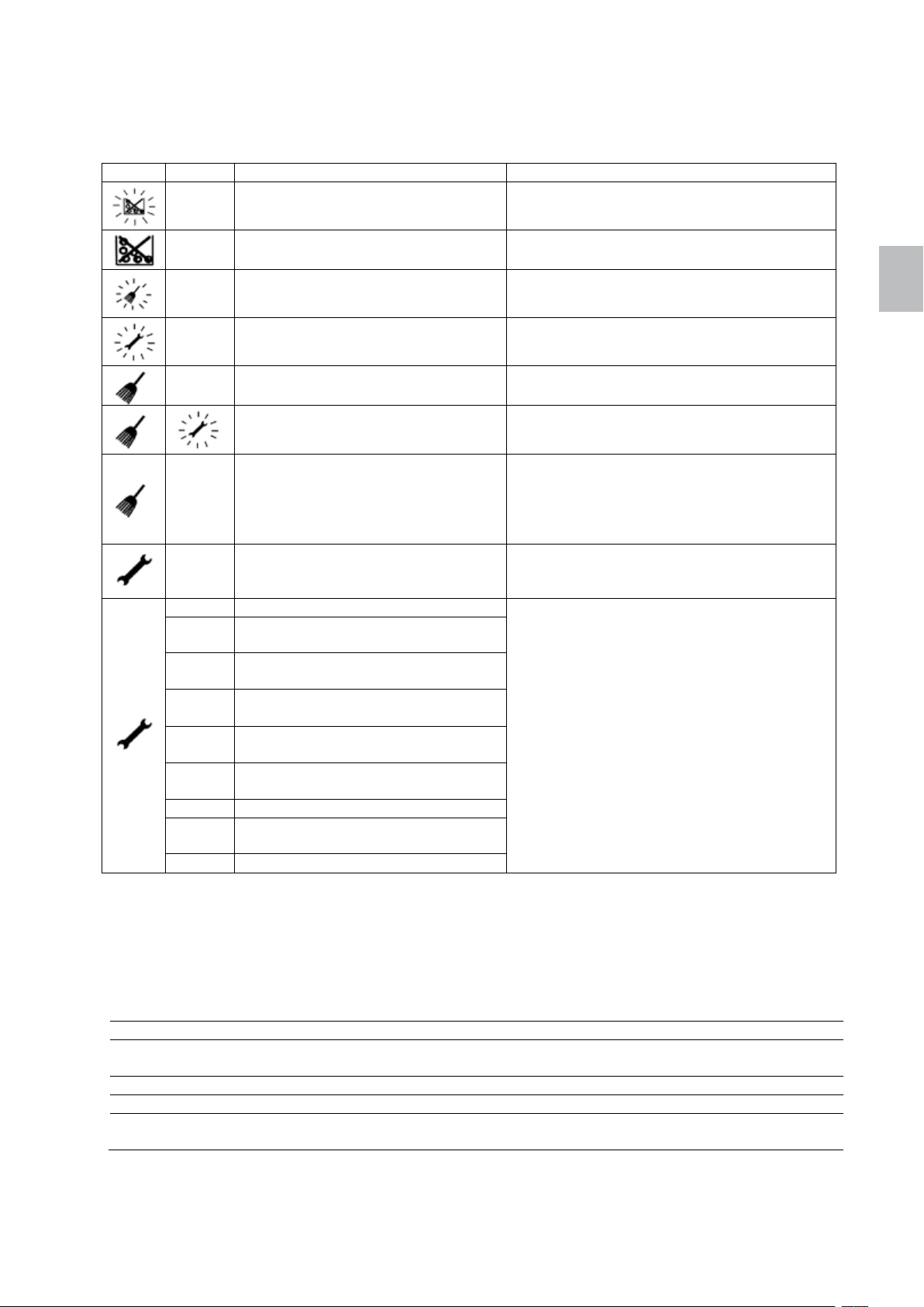
Polly 37 italiano
Spia
Codice
Causa
Soluzione
Ogni allarme e ogni errore è correlato con un codice che consente di identificare il problema. Per
visualizzare il codice tenere premuto il tasto Annulla. Se il codice di allarme o di errore non esiste, sul
display compare "----" .
A001 Basso livello di combustibile Rifornire di combustibile
---- Il combustibile manca Rifornire di combustibile
A003
A004 La batteria è debole
---- Sensore aria sporco
----
E109
E001 Errore del pannello comandi
E004
E101
E107
E108
E109
E110 Errore sensore ambiente (NTC1)
E112
E115 Errore generale
Per confermare il messaggio di errore, tenere premuto il tasto On/Off finché il simbolo non si spegne
Camera di combustione o canna
fumaria sporca
Sensore aria difettoso Sostituire il sensore aria
Sportello della camera di
combustione aperta,
cassetto raccoglicenere non inserito,
la griglia non chiude
Coperchio del serbatoio non
perfettamente chiuso,
impossibile chiudere la griglia
Errore di comunicazione scheda
principale
Sovratemperatura nella camera di
combustione
Errore sensore temperatura fiamma
(TC2)
Errore limitatore temperatura di
sicurezza
Errore pressostato nel coperchio del
serbatoio
Sovratemperatura sensore camera
di combustione
Controllare la camera di combustione, far
pulire la canna fumaria
Cambiare la batteria
vedere il punto 5. Cambio della batteria
Estrarre il sensore aria e rimuovere lo sporco
dal sensore di misura tramite soffiaggio
Chiudere lo sportello della camera di
combustione,
introdurre il cassetto raccoglicenere
Pellet tra griglia e braciere, controllare il
motoriduttore
la griglia non chiude
Annotare il codice di errore e contattare il
personale dell'assistenza
italiano
6.1 Spie LED sulla centralina
La centralina è dotata di due spie LED che forniscono informazioni sul funzionamento della centralina.
Nella tabella sottostante è descritto il significato dei segnali LED:
Segnale LED 2 LED 1
Funzione Controllo dell'alimentazione
elettrica
OFF Nessuna alimentazione elettrica Anomalia o non programmato
Acceso Alimentazione elettrica ok –
Lampeggia rapidamente
(5 volte al secondo)
– Comunicazione ok
Controllo della comunicazione
Page 40

italiano
italiano 38 Polly
6.2 Interruzione dell'alimentazione elettrica
Durante un'interruzione dell'alimentazione elettrica la centralina rimane attiva grazie alla batteria interna:
In caso di interruzione dell'alimentazione elettrica la centralina funziona nel modo seguente:
Durata
dell'interruzione di
corrente
Inferiore a 1 minuto Phase Fire up (fase di
Inferiore a 1 minuto Phase Fire up (fase di
Funzionamento prima
dell'interruzione di
corrente
riscaldamento)
Phase Burning
(combustione)
OFF (spento) OFF (spento)
riscaldamento)
Phase Burning
(combustione)
OFF (spento) OFF (spento)
Funzionamento dopo l'interruzione di corrente
La centralina continua a funzionare
normalmente.
La centralina controlla la temperatura dell'aria
e continua a funzionare nella fase di
combustione o avvia la fase del riscaldamento.
La centralina continua a funzionare
normalmente.
La centralina controlla la temperatura dei fumi.
In caso di abbassamento della temperatura
dei fumi al di sotto del valore PAR56 la stufa
riavvia la fase di riscaldamento, altrimenti
continua a funzionare nella fase di
combustione.
6.3 Errori indeterminati sul pannello comandi
Alcune informazioni memorizzate nella centralina vengono aggiornate sul pannello comandi all'avvio (ad
esempio la configurazione).
Se vengono effettuate modifiche alla centralina e il pannello comandi visualizza errori inattesi, ripristinare
il pannello staccandolo e quindi ricollegandolo all'alimentazione elettrica. Se il problema persiste,
contattare il personale dell'assistenza.
7 Pulizia
Gli intervalli di pulizia dipendono in larga parte dal luogo di installazione e dalle ore di funzionamento,
pertanto i tempi riportati nella seguente tabella sono indicativi. I componenti indicati qui di seguito devono
comunque essere sempre puliti considerando il loro livello di imbrattamento.
Pulizia del vetro di ispezione 2-3 giorni
Controllo visivo del braciere e della griglia, rimuovere i depositi incrostati 2-3 giorni
Svuotamento del cassetto raccoglicenere e pulizia della camera di combustione 7-14 giorni
Cambio del filtro dell'aria 1-2 mesi
Pulizia delle canne fumarie, del convogliatore dei fumi e delle ventole a tiraggio indotto 1 x anno
Pulizia del sensore per la temperatura della camera di combustione (solo con un
panno asciutto)
Pulizia del sensore aria (con soffiaggio sul filo di misurazione) 1 x anno
Cambio della batteria 2 - 3 anni
Controllo di tutte le guarnizioni (sportello, cassetto raccoglicenere, griglia, coperchio
del serbatoio); effettuare le sostituzioni necessarie
Pulizia del comignolo come da indicazioni dello spazzacamino specializzato almeno 1 x
1 x anno
1 x anno
anno
Page 41
Polly 39 italiano
8 Dichiarazione di conformità
italiano
9 Garanzia
Per la stufa a pellet AUSTROFLAMM garantiamo un funzionamento ineccepibile di 6 anni per il corpo
della stufa e di 2 anni dalla data della prima vendita per tutti gli altri componenti in acciaio e in ghisa.
Provvediamo alla sostituzioni delle parti in acciaio e in ghisa che nel periodo di garanzia presentano difetti
nei materiali o di lavorazione.
Non garantiamo le parti soggette ad usura (ad es.: refrattario, guarnizioni, base grigliata e componenti
elettrici ed elettronici come indicati al punto 11.2), rivestimenti superficiali, verniciature, vetro e ceramiche.
Le prestazioni di garanzia valgono alle seguenti condizioni:
3. L'utente utilizza la stufa a pellet AUSTROFLAMM nel rispetto delle istruzioni per l'uso e l'installazione
è stata effettuata da personale qualificato.
4. Per usufruire del diritto di garanzia la scheda di garanzia debitamente compilata deve essere
presentata presso un rivenditore AUSTROFLAMM accompagnata dalla fattura.
IMPORTANTE: La nostra garanzia copre la fornitura gratuita delle parti nuove. Non comprende i
tempi di intervento e di trasferta del personale. Rivendicazioni di garanzia ingiustificate verranno
riaddebitate all'utente.
Page 42
englisch
Table of Contents
1 Important information for stove operators .............................................................. 41
2 Fuel ........................................................................................................................ 41
3 Outer dimensions and technical data ..................................................................... 42
4 Use of the control panel ......................................................................................... 43
4.1 Control panel ................................................................................................... 43
4.2 Menu structure ................................................................................................. 45
4.3 Navigating through the menu ........................................................................... 46
4.4 Setting the clock .............................................................................................. 46
4.5 Setting the ambient temperature...................................................................... 46
4.6 Setting the output level .................................................................................... 47
4.7 Setting the weekly switching program .............................................................. 47
4.8 Changing of the setup options ......................................................................... 48
5 Maintaining the control unit .................................................................................... 49
5.1 Replacing the battery ....................................................................................... 49
6 Troubleshooting ..................................................................................................... 50
6.1 LED display on the control unit ........................................................................ 50
6.2 Failure of the power supply .............................................................................. 51
6.3 Undetermined error at the control panel .......................................................... 51
7 Cleaning ................................................................................................................ 51
8 Declaration of Conformity ...................................................................................... 52
9 Guarantee .............................................................................................................. 52
Functional diagram ....................................................................................................... 53
Function/components – description .............................................................................. 53
Main stove components ............................................................................................ 53
Electrical and electronic component .......................................................................... 54
Combustion chamber lining ....................................................................................... 55
Door components ...................................................................................................... 56
Circuit diagram .............................................................................................................. 56
Assembly work on the stove ......................................................................................... 57
Side shrouding and cover disassembly/assembly ..................................................... 57
Upper door hinge adjustment .................................................................................... 58
Lower door hinge adjustment .................................................................................... 59
Rear wall removal...................................................................................................... 60
Flue gas duct cleaning, emptying of the ash box ...................................................... 61
Filter replacement...................................................................................................... 63
Replacement of burner bowl spacer ring ................................................................... 64
Page 43
Polly 41 english
NOTES:
1 Important information for stove operators
• The information in these user instructions is of a general nature. National and European standards,
local and building regulations, as well as fire marshal provisions, must be complied with.
• These user instructions must be attentively read prior to setting up and using the wood stove, and
before any intervention in it. Keep the user instructions carefully stored and ensure that they are
always available next to or near the wood stove.
• Compliance with the rules contained herein ensures personal and material safety, economical
operation and a long service life.
standards and directives
account.
• No components may be modified or replaced by other parts which are not original equipment
manufacturer parts, otherwise the guarantee coverage and usage approval shall be rendered null and
void.
• Disconnect the power supply to the wood stove prior to any intervention.
• Schematics and drawings delivered along with the stove only serve as demonstrative examples; the
manufacturer pursues a policy of continuous development and updating of the product and may
undertake changes at any time without prior notification.
• All dimensions stated in these user instructions are in mm.
• CAUTION: The equipment may only be commissioned by specialists trained by the manufacturer.
• Your heating unit is not suited for use as a ladder or support stand.
• Please note that the surfaces of the pellet stove heat up substantially during operation. Always wear
protective gloves when using the pellet stove. Inform children as to the danger and keep them away
from the fire chamber during operation.
• Only use pellets as described under Item 2. Fuel.
• Placing non-heat-resistant objects on the heating unit or in its vicinity is prohibited.
• Do not place any laundry items on the stove to dry. Laundry racks or the like must be kept at a
sufficient distance from the heating unit fire hazard!
• It is prohibited to handle highly flammable and explosive substances in the same or adjacent rooms
when operating the heating unit.
• It must be ensured that adequate combustion air intake and safe exhaust of the fumes is provided for.
Therefore you should always check whether there is any blockage in the chimney, especially after a
lengthier operational interruption.
• The convection grid may never be closed, not even partially.
• Venting devices which are operated in the same room or room cluster along with the fire chamber can
cause problems.
• The pellet stove must, depending on the degree of filth, be regularly cleaned (see Item 7. Cleaning,
13.5 Flue gas duct cleaning and 13.6 Filter replacement).
• Repairs to your pellet stove may only be performed by specialists trained by the manufacturer.
• Have parts replaced as necessary and depending on the condition.
electrical and electronic elements for damage, wear and tear
Electrical and electronic elements).
• Safety devices may not be bypassed.
For the planning and construction of the wood stove, all
under Item 8. Declaration of Conformity have been taken into
Regularly check the
(see also Item 11.2
englisch
2 Fuel
Pellets are a fuel produced by compressing sawdust from untreated wood, i.e. without any coating, glue
or the like.
The varying quality of pellets also causes different "crusting" in the burner bowl and on the grate of the
wood stove. With regard to this, it is recommended to use pellets that do not contain an artificial binder
and which leave the least amount of unburned residue possible. The stove has been tested with pellets
as per ÖN (Austrian Standards Institute) EN 14961-2 and ENplus.
Using low-quality pellets or other material damages the functions of your wood stove and
can void the guarantee and the associated manufacturer's responsibility.
The equipment also requires a few burner cycles until the control unit has optimally
adapted to its ambient conditions.
Page 44
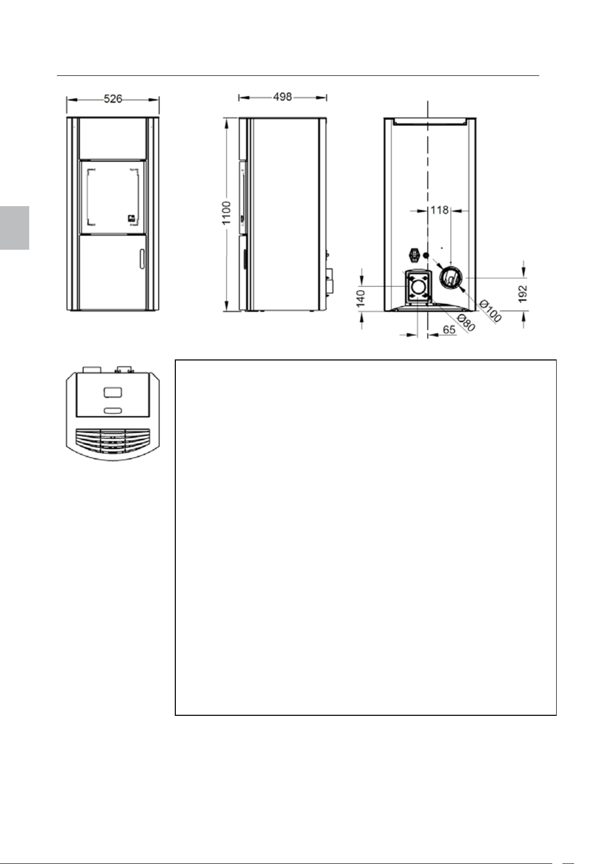
Fuel Pellets
englisch
english 42 Polly
3 Outer dimensions and technical data
Nominal thermal output (NWL) 8 kW
Partial-load thermal output 2.4 kW
Space heating capacity 55 – 190 m³
Degree of efficiency > 90%
CO content at NWL <180 mg/Nm³
CO content at partial-load 155 mg/Nm³
Flue gas temperature at NWL 150 °C
Flue gas mass flow rate at NWL 4.4 g/s
Flue gas mass flow rate at partial-load 3.2 g/s
Holding capacity, full tank 26 kg / 40 l
Pellet consumption min./max 0.6 – 1.8 kg/h
Autonomy min./max approx. 12 - 40 h
Air connector Ø 80 mm
Flue connector Ø 100 mm
Current upon switching on 300 W
Operating current 50 W
Voltage / current frequency 230 V / 50 Hz
Voltage fluctuations 0.9 - 1.1 of the rated voltage
Frequency fluctuations 0.99 - 1.01 of the rated frequency, constant
0.98 - 1.02 short-term
Dimensions H x W x T 1100 x 526 x 498 mm
Weight 150 kg
Minimum spacing side 150 mm
rear 100 mm
front 800 mm
Temperature limits 0 - 40°C
Relative humidity non-condensing
Installation location above sea level < 1000 m
Page 45
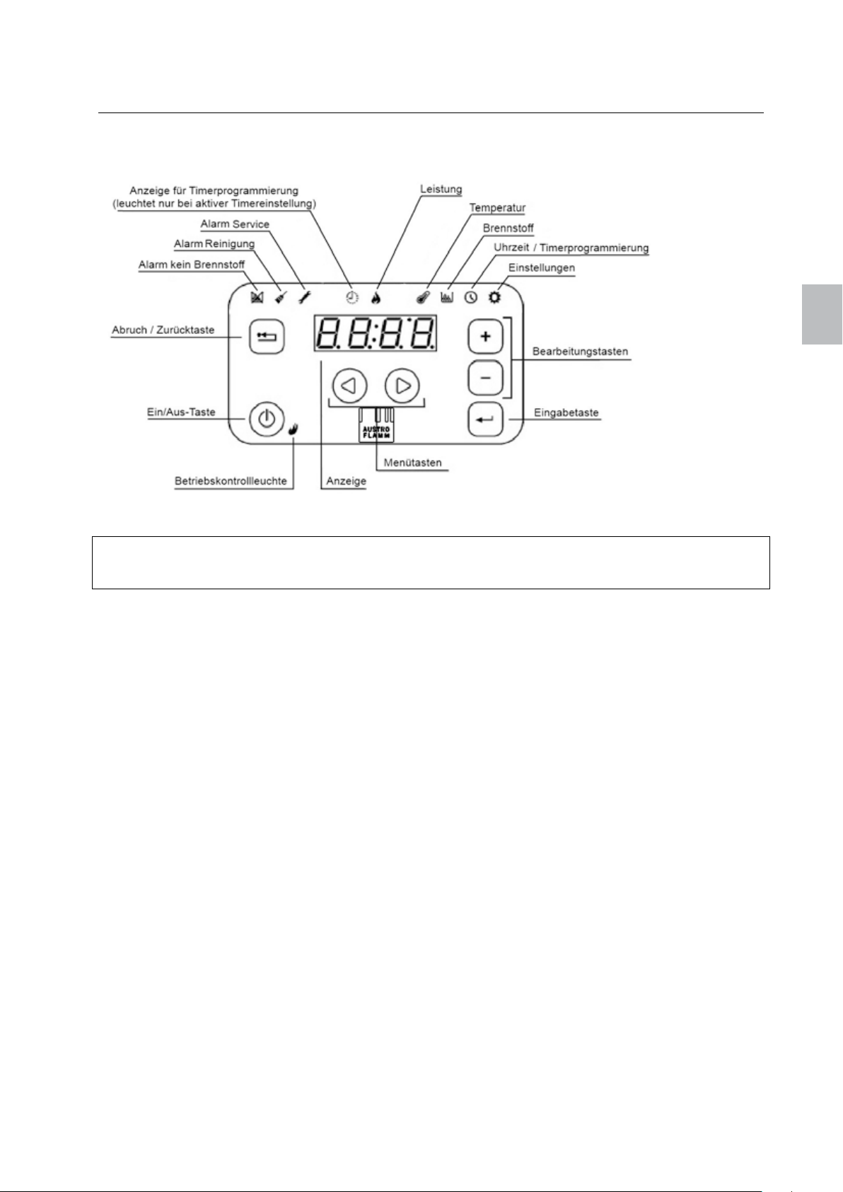
Polly 43 english
4 Use of the control panel
4.1 Control panel
englisch
Figure 10: Control panel
Note
Always keep the control panel clean for optimum performance. Spots on the keys, e.g. from grease, can
trigger a signal as if a key was being pressed.
The touch-control panel is intuitively designed. Display symbols for various alarms are located along the
upper edge of the control panel, timer operation and the menus.
The display shows the set or current values for the presently selected menu option. The keys serve to
navigate through the menu and control operation of the control unit. A description of the keys can be
found in
Tabelle 1: Tasten des Bedienfelds on page 44.
The control panel also has a buzzer that provides feedback signals to the control panel. The following
acoustic signals are possible:
• Short, high-pitched tone: Signals during navigation through the menu and editing of the settings.
• Long, low-pitched tone: Signals an improper action (e.g. wrong key pressed).
• Long, high-pitched tone: In case of an alarm, this tone is signaled at the volume set by the user.
Contrarily, in case of an error the tone signals at full volume.
A description of the alarms and errors can be found in Chapter Fehlerbehebung on Page 50.
Page 46
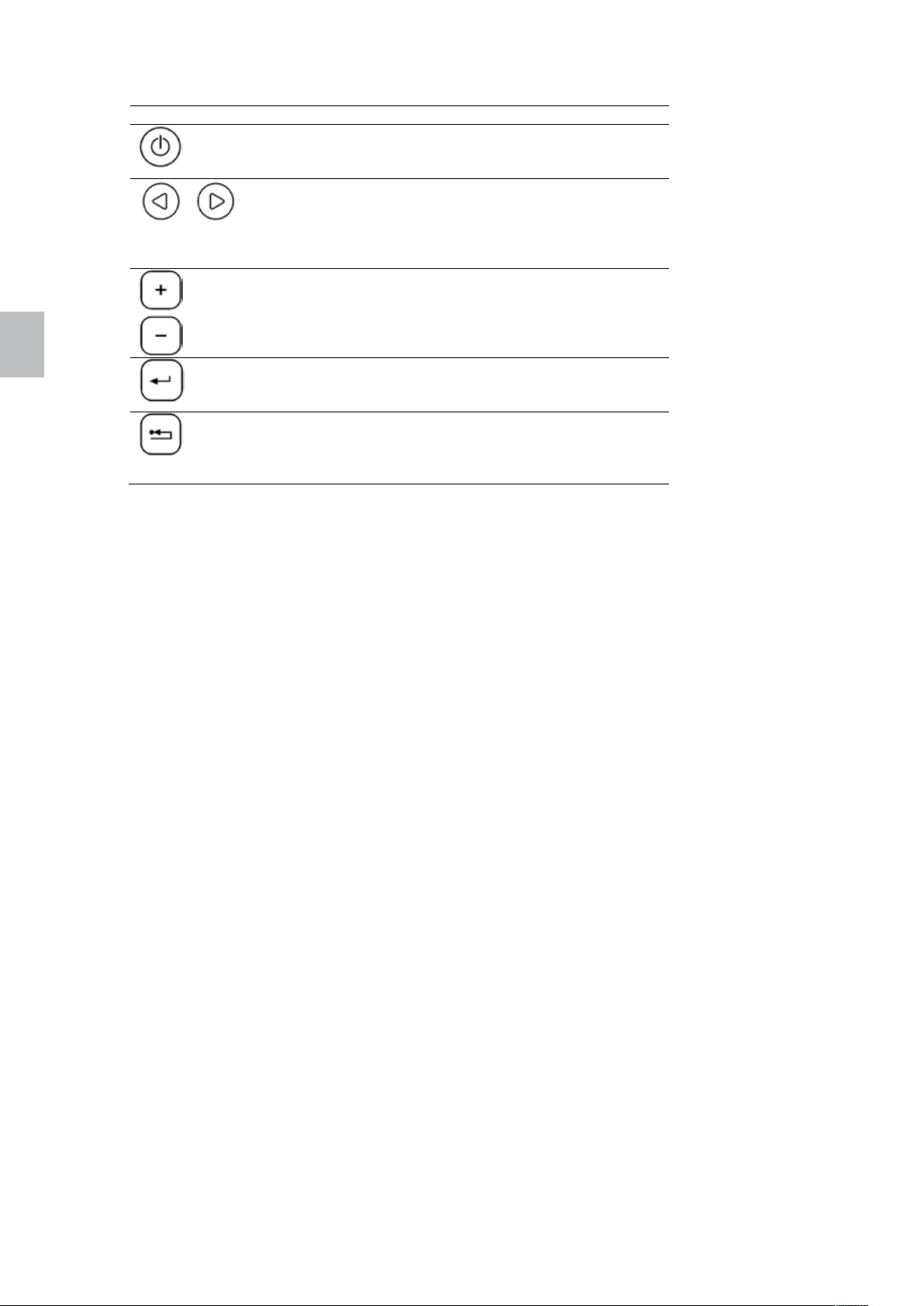
englisch
english 44 Polly
Key Description
The fire chamber can be turned on or off with the
Table 3: Keys of the control panel
on/off key. To to this, keep key 1 pressed for several
seconds.
The menu keys (arrow keys) serve to navigate
through the first menu level. The presently selected
menu is indicated by the corresponding symbol
displayed on the upper edge. These keys are used in
the Edit mode.
The editing keys (plus and minus key) serve to
navigate through the submenus and to
increase/decrease values in the Edit mode when the
selected value is blinking.
The Edit mode is called up with the Enter key. In
addition, it serves to confirm the set values and to
select further submenus.
The Cancel key serves to reject the changes and
return to the next higher menu level. If this key is kept
pressed for longer than 3 seconds, the last error or
alarm code will be displayed.
Page 47
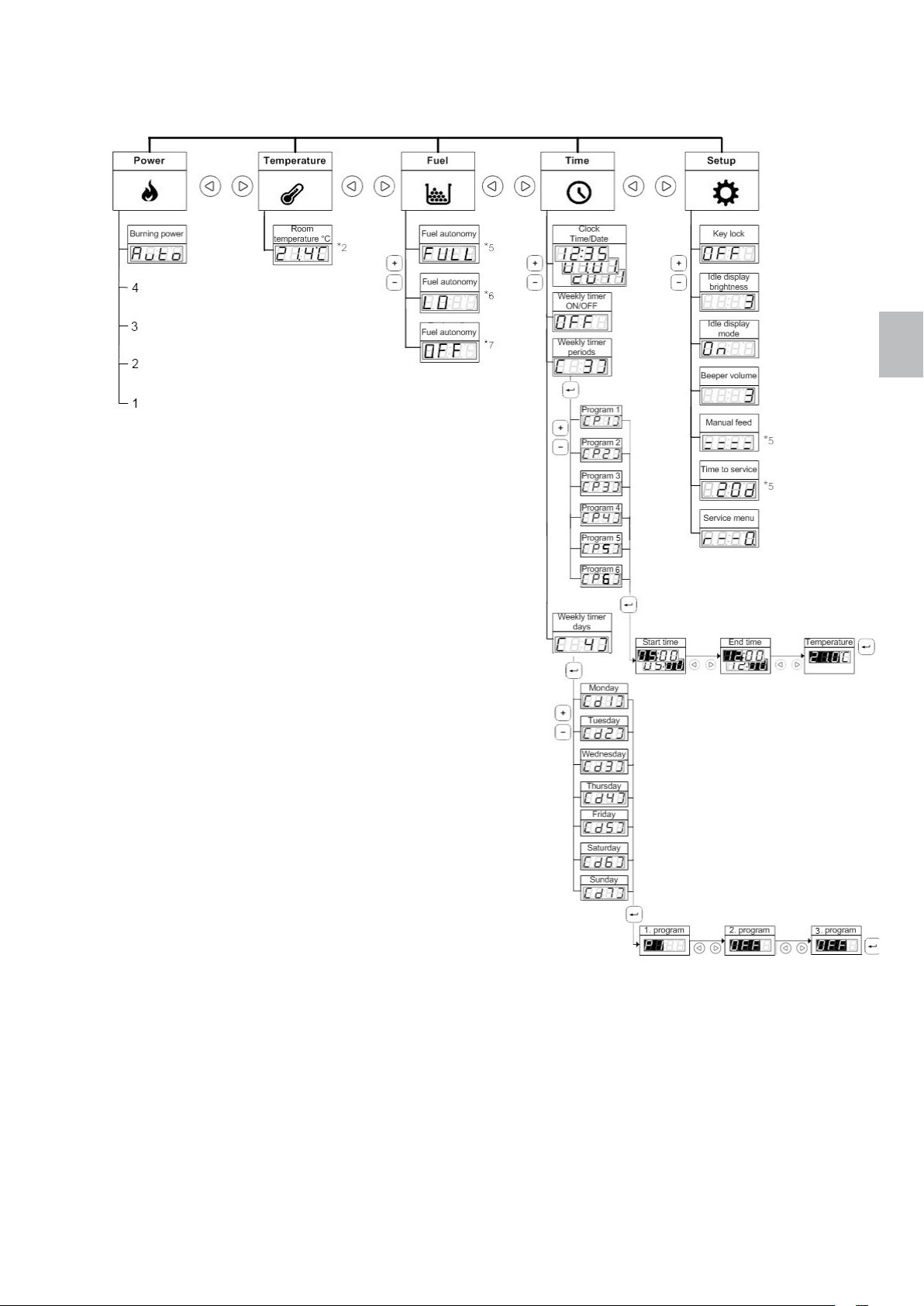
Polly 45 english
4.2 Menu structure
englisch
Figure 11: Menu structure
Page 48

englisch
english 46 Polly
4.3 Navigating through the menu
You can navigate through the first menu level using the left and right arrow keys. The symbol for the
selected menu lights up. The setting for the first submenu option is shown on the display.
Using the plus and minus keys, you can navigate upward or downward in the second menu level (the
submenu). The menu structure shown in Figure 2 is reversed, so that it looks as if you would navigate
downward in the menu; actually, you navigate upward. To simplify navigation through the second menu
level, the number of the respective menu options is shown shortly in brackets.
To change a setting in the menu, press the Enter key. This activates the Edit mode for the selected
setting. The displayed value begins to blink. Change the value using the plus and minus keys. You can
navigate through the steps in the Edit mode using the left and right arrow keys. In conclusion, press the
Enter key to save the setting and exit the Edit mode. The menu option which you edited is then shown
again on the display.
The display shows either the set or actual value, depending on the setting. When changing the
temperature, for example, enter the desired ambient temperature. After you have left the Edit mode, the
actual temperature will be shown on the display (which can differ from the set temperature).
To call up the third menu level, press the Enter key. You can then go from one menu option to another by
using the plus or minus keys. The procedure for changing the settings is the same as for the second
menu level.
To exit the Edit mode without saving the changes, press the Cancel key. With this key you can also return
to a previous level in the menu. If, for instance, you are editing program 3 under the menu option "Weekly
Timer Periods", you can reject the changes with Cancel key and return to program 3. By pressing the
Cancel key you go to "Weekly Timer Periods", then to "Clock" and finally to "Burning Power" under the
"Power" menu.
4.4 Setting the clock
You can set the current time and date by means of the control panel. To show the current time, go
through the menu by pressing the menu key for the menu "Time". The current time is then shown on the
display.
To set the current time and date, in the "Time" menu press the Enter key. The hour value starts blinking.
Set the desired hour using the edit keys. Then press the right menu key. The minute value starts blinking.
Set the desired minutes. Press the right menu key and set the date in the same manner. The date format
is specified as DD.MMM.YYYY Then press the right menu key and set the day of the week. Select
corresponding number between 1 (Monday) and 7 (Sunday). Confirm the time and date settings by
pressing the Enter key.
4.5 Setting the ambient temperature
The control unit offers two possibilities for setting the ambient temperature. These are:
- Use of weekly switching programs
- Manual setting or changing of the ambient temperature
With the aid of the weekly switching program you can automate operation of the fire chamber so that very
little or no user intervention is necessary. For detailed information, see Chapter Einstellen der
Wochenschaltprogramme on Page 8.
You can also manually set or change the ambient temperature. By using the weekly switching program
you can temporarily override the program settings. The program settings will be reset if certain conditions
specified for the timer have been fulfilled (for example, if the end time has been reached and the fire
chamber switches off).
Page 49
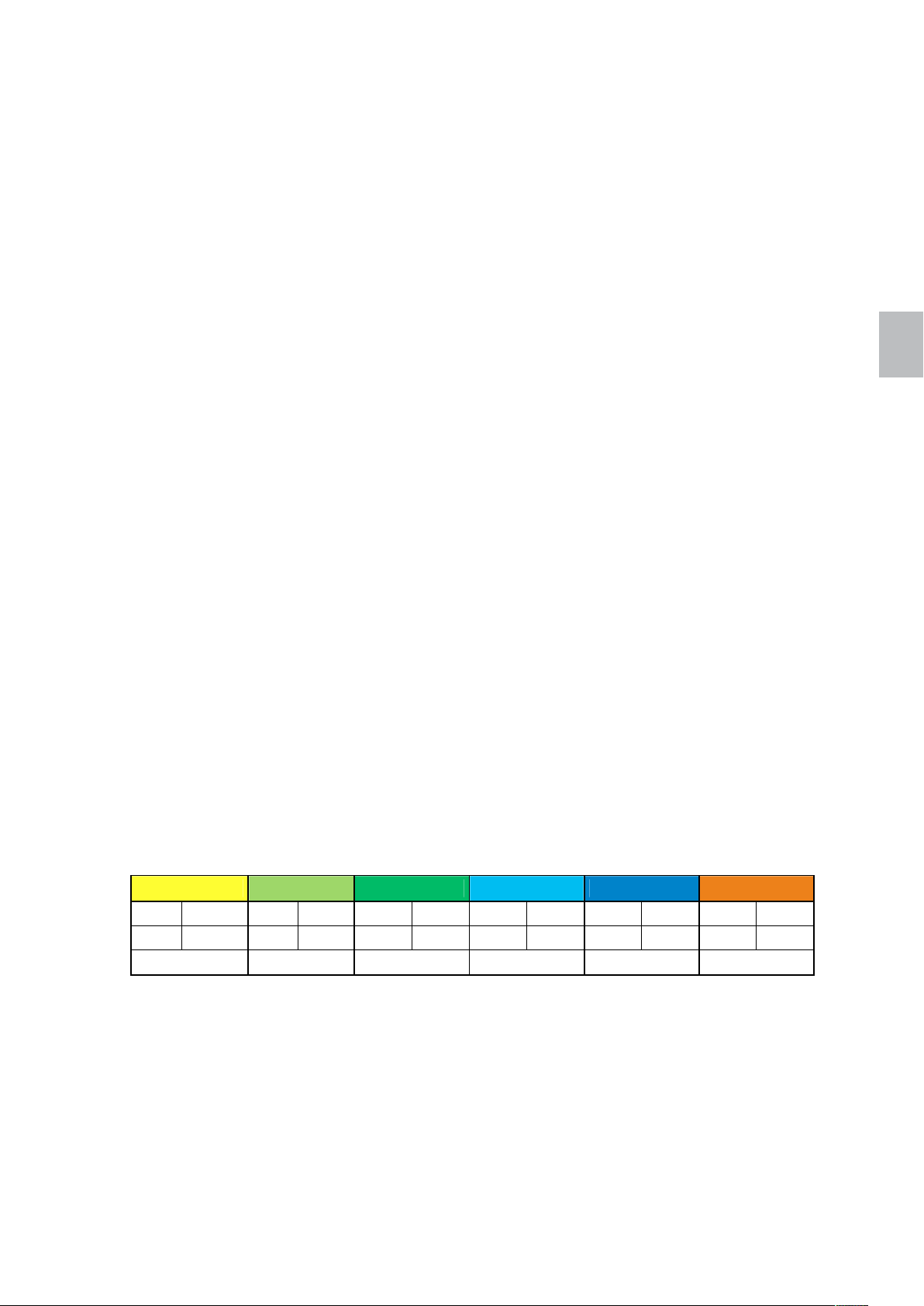
Polly 47 english
To show the current ambient temperature, go through the menu by pressing the menu key for the menu
"Temperature". The current ambient temperature is then shown on the display.
To set the desired ambient temperature, in the "Temperature" menu press the Enter key. On the display,
the set target temperature is shown in the Edit mode (the value blinks). You can raise or lower this value
with the Edit keys. To complete, press the Enter key to confirm the set temperature. The current ambient
temperature is then shown on the display.
4.6 Setting the output level
The control unit regulates the fire chamber so that optimum output is ensured. You can override this
setting and reduce the burner output, thus saving fuel. The setting influences the fuel supply rate and
blower speed. The desired ambient temperature is more slowly attained this way, which can more quickly
lead to (glass pane) contamination.
The setting of the burner output pertains to the maximum burner output that the fire chamber generates to
heat the surrounding area. Once the set temperature has been attained, the burner output is
automatically cut back.
To show the current burner output, go through the menu by pressing the menu key for the menu "Power".
The current burner output is then shown on the display.
You can constrain the setting of the burner output to slowly heat up to the desired ambient temperature.
For this, press on the Enter key in the "Power" menu. On the display, the burner output is shown in the
Edit mode (the value blinks). Using the Edit keys, you can set this value to either Automatic (max. output),
4, 3, 2, or 1 (min. output). To complete, press the Enter key to confirm the set burner output. The current
burner output is then shown on the display.
englisch
4.7 Setting the weekly switching program
With the control unit you can set the weekly switching program and thus automate operation of the fire
chamber. Six different programs can be set, whereby a max. of three programs can be selected for each
weekday. The program determines the start and finish times, as well as the desired temperature.
"
To set a program, call up the menu "Time
"
the entry "Weekly timer periods
"
Program 1". On the display, [ P1 ] is shown. Press the Enter key again to switch to the Edit mode for
Program 1. The hour value of the starting time blinks. Set the desired hour for the starting time using the
edit keys. Then press the right menu key. The minute value of the starting time blinks. Set the desired
minutes for the starting time. Press the right menu key and set the desired end time. Then, press the right
menu key to set the desired ambient temperature for the selected time period. Confirm the program
settings by pressing the Enter key. Repeat the previous steps to set the other programs.
Example:
Program 1 Program 2 Program 3 Program 4 Program 5 Program 6
ON OFF ON OFF ON OFF ON OFF ON OFF ON OFF
05:30 07:30 08:00 11:30 12:00 23:00 17:00 23:00 20:00 22:30 04:00 07:00
16 °C 18 °C 19 °C 18 °C 17 °C 15 °C
To designate the programs to weekdays, call up the menu "Time
the Edit key to select the entry "Weekly timer days
key to select "
mode for Monday. The value for the 1st program blinks. Set the desired program using the edit keys.
Then press the right menu key. The value for the 2nd program blinks. Set the desired program.
Monday". On the display, [ d1 ] is shown. Press the Enter key again to switch to the Edit
. On the display, [ 3 ] is shown.
don't want to use all of the program places, then set this to
Confirm the program settings by pressing the Enter key. Repeat the previous steps to set the programs
for all weekdays.
Example:
by pressing the menu key. Then, press the Edit key to select
Press the Enter key to select
"
by pressing the menu key. Then, press
"
. On the display, [ 4 ] is shown.
Press the Enter
If you
[ OFF ]
with the minus key.
Page 50
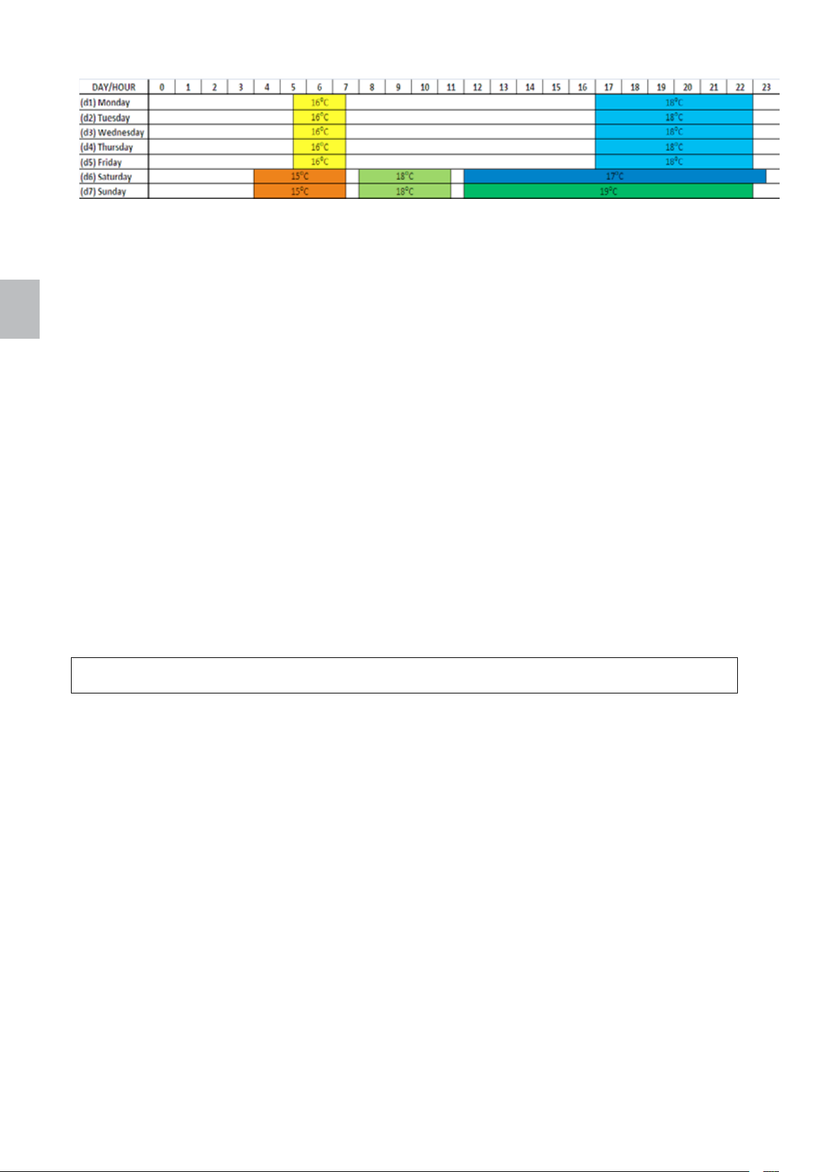
english 48 Polly
englisch
In order to activate or deactivate operation of the fire chamber with the weekly switching programs, call up
the Time menu by pressing the menu key. Then, press the Edit key to select the entry "Weekly timer
"
ON/OFF
weekly timer, manually configure operation of the fire chamber.
. Press the Enter key and switch the weekly timer either ON or OFF. If you deactivate the
4.8 Changing of the setup options
In the "Setup" menu you can set the options for:
[ 1 ]… "Key lock"
[ 2 ]… "Idle display brightness"
[ 3 ]… "Idle display mode"
[ 4 ]… "Beeper volume", and
[ 6 ]… "Manual feed"
.
"
With the "Key lock
to the settings. When the key lock is activated you can navigate through the menu and display the current
values, but you cannot edit any the of settings, however, with the exception of the key lock itself. The Key
lock setting offers the following options:
- OFF: The key lock is deactivated, all keys can be actuated.
- Lo: The Edit mode is deactivated (the Enter key is locked).
- Hi: The Edit mode and on/off function are deactivated (the Enter key and ON/OFF key are
locked).
Tip!
We recommend that you activate the key lock before cleaning the control panel.
You can increase or decrease the brightness of the display in the idle state to save energy. As soon as
you touch the control panel the brightness of the display increases to the standard the value.
The "Idle display mode" setting offers the following options:
- OFF: The control panel remains in the selected menu. If the Edit mode was active, the changes
are rejected and the Edit mode is departed.
- Option 1: The control panel departs the current menu and alternately displays the current ambient
temperature and time.
- Option 2: The control panel departs the current menu and opens the "Temperature" menu. The
current ambient temperature is then shown on the display.
- Option 3: The control panel departs the current menu and opens the "Clock" menu. The current
time is then shown on the display.
The "Beeper volume" setting controls the volume of the acoustic signals of the control panel.
With the "Manual feed" option the pellet feed can be manually started. The feed supply operates briefly
and then stops. With this option you can clean, empty or refill the feed supply components.
To show the current setup options, go through the menu by pressing the menu key for the menu "Setup".
The set display brightness in the idle state is shown. With the Edit keys you can show the settings of the
option the control panel can be locked so that no unintentional changes can be made
Page 51
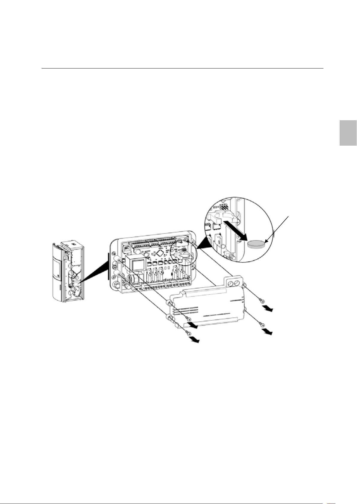
Polly 49 english
individual setup options. To change a setting, press the Enter key and increase/decrease the value with
the aid of the Edit keys. To complete, press the Enter key to confirm the set value.
5 Maintaining the control unit
5.1 Replacing the battery
During a power failure, or if the mains power supply is cut off, the control unit switches to internal battery
power supply. The battery supplies the internal clock and internal memory of the microprocessor.
If the battery is empty, the control unit functions normally as long as the mains power supply is
connected. In the event of a power failure, the internal clock stops and the operating phase is not saved
in the memory. After the power supply has been restored, the clock is reset and the control unit remains
in the phase OFF (Stove mode) or "Fire up" (Boiler mode).
To replace the battery:
11. Disconnect the mains power supply.
12. The battery is located on the circuit board (see Abbildung 3). For this, the side shrouding must be
removed (see 13.1).
13. Take out the old battery out of its receptacle using INSULATED pliers or a similar tool. Ensure
that you do not bend the contacts of the battery receptacle.
14. Insert the new battery while observing that the correct polarity is maintained (see Abbildung 3).
15. Reconnect the mains power supply.
Button battery
CR2032
Figure 12 Replacing the battery
englisch
Page 52
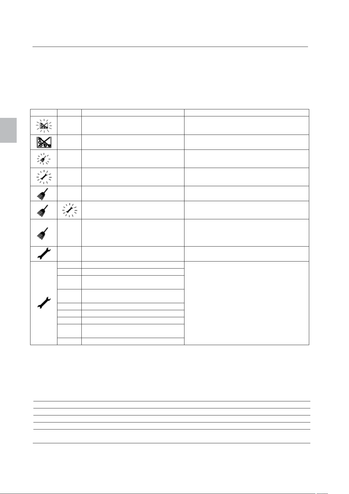
Display
Code
Cause
Solutions
englisch
english 50 Polly
6 Troubleshooting
The control panel conveys messages and warnings for alarms and errors that occur while using the
control unit. The display symbols indicate a problem. In case of an alarm, the symbols blink; in case of
errors, the symbols remain continuously illuminated. In the event of an alarm, the fire chamber is still
capable of functioning; in the event of an error, there is a severe functional malfunction of the fire
chamber and the service personnel must be informed.
Every alarm and error is assigned a code with which the problem can be identified. To display the code,
keep the Cancel key pressed. If no alarm/error code is available, "----" will be shown on the display.
A001 Low fuel level Refill fuel level
---- No fuel Refill fuel level
A003 Combustion chamber or flue is dirty
A004 Battery is weak
---- Air quantity sensor is dirty
----
E109
E001 Control panel error
E004 Mainboard communications error
E101
E107
E108 Safety temperature delimiter error
E109 Tank lid pressure switch error
E110 Room sensor error (NTC1)
E112
E115 General error
To acknowledge the error message, keep the ON/OFF key pressed until the symbol no longer lights up.
Air quantity sensor is defective Replace air quantity sensor
The door combustion chamber door
is open,
the ash box is not in place,
grate does not close
Tank lid not completely closed,
grate cannot close
Excessive temperature in the
combustion chamber
Flame temperature sensor error
(TC2)
Combustion chamber sensor excess
temperature
Check and empty the combustion chamber,
have the flue swept
Replace battery
See Item 5. Replacing the battery
Remove air quantity sensor and blow away
dirt from measurement sensor
Close the door to the combustion chamber,
put in ash box,
check for pellets between grate and burner
bowl, grate motor
Remove possibly stuck pellets
Take note of the error code and contact the
service personnel
6.1 LED display on the control unit
The control unit has two LED displays that provide information on the control unit operation. The LED
signals are described in the table below:
Signal LED 2 LED 1
Function Checking the power supply Checking the communication
OFF No power supply Malfunction or not programmed
Illuminates Power supply OK –
Blinks rapidly
(5 times per second)
– Communication OK
Page 53

Polly 51 english
6.2 Failure of the power supply
During a power failure, the control unit continues to remain active thanks to the battery.
In the event of a power failure, the control unit operates as follows:
Duration of the
power failure
Less than 1 minute Phase Fire up The control unit continues operating normally.
More than 1 minute Phase Fire up The control unit continues operating normally.
Operation before the
power failure
Phase Burning The control unit tests the air temperature and
OFF OFF
Phase Burning The control unit tests the temperature of the
OFF OFF
Operation after the power failure
either continues operating in the Burning
phase or restarts in the Fire up phase.
flue gases. If the flue gas temperature has
fallen below the value of PAR56, the fire
chamber restarts in the Fire up phase or
otherwise continues to operate in the Burning
phase.
6.3 Undetermined error at the control panel
englisch
Upon starting up, certain information stored in the control unit is updated on the control panel (e.g. the
configuration).
If changes have been made to the control unit and the control panel unexpectedly shows an error, reset
the control panel by disconnecting and then reconnecting it. If the problem is still present, please contact
the service personnel.
7 Cleaning
Because cleaning intervals depend greatly on the installation location and operating hours, the times
stated in the following table can only be considered to be reference values. Basically, all of the following
components must be cleaned depending on their degree of contamination.
Cleaning the viewing window 2-3 days
Visual inspection of the burner bowl and grate, remove clinging deposits 2-3 days
Emptying of the ash box and cleaning of the combustion chamber 7-14 days
Replacement of the air filter 1-2 months
Cleaning of the flue gas ducts, flue gas collectors and exhaust duct blowers Once a year
Cleaning of the combustion chamber temperature sensor (only with a dry cloth) Once a year
Cleaning of the air quantity sensor (blowing clean the measuring wire) Once a year
Replace the battery 2 - 3 years
Inspecting all seals (door, ash box, grate, tank lid); replace as the case may be Once a year
Cleaning of the chimney as per the chimney sweep specialist Min. once a
year
Page 54
englisch
english 52 Polly
8 Declaration of Conformity
9 Guarantee
For your AUSTROFLAMM pellet stove, we guarantee the flawless function of the main structure for 6
years and for 2 years for all further components made of steel and cast iron, starting from the date of
initial purchase. Parts made of steel or cast iron which have been proven to have material or
workmanship defects shall be replaced by new parts.
We provide no guarantee on wear and tear parts (e.g.: Keramott, seals, bottom grate and all electrical
and electronic components as per Item 11.2), surface coatings, paint, glass and ceramics.
Prerequisites for our guarantee coverage are:
5. Your AUSTROFLAMM has been operated in accordance with with the user instructions and was
installed by a qualified specialist.
6. A guarantee claim is enforced by presenting a completely filled out guarantee card and the invoice to
a AUSTROFLAMM specialist dealer.
Our
IMPORTANT:
and travel times are not included. An unjustified claim for guarantee coverage shall be charged back to
the operator.
guarantee coverage comprises the free delivery of the new parts. Labour hours
Page 55
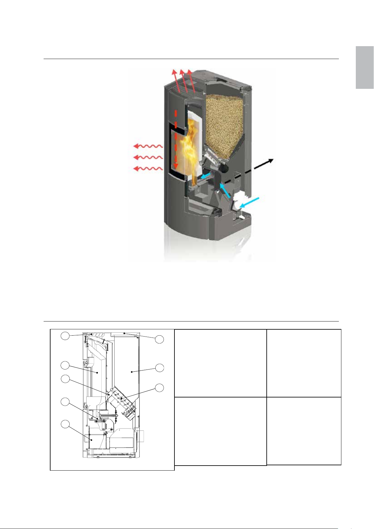
Polly 53 Polly
4
5
6
7
8
1
2 3
8……..Cassetto
10. Funktionsschema / Schéma / Schema di funzionamento /
Functional diagram
de / fr / it / en
11. Funktion/Komponenten – Beschreibung / Fonction / Composants
– Description / Funzione/componenti – descrizione /
Function/components – description
11.1. Hauptbestandteile Ofen / Eléments principaux du poêle /
Componenti principali della stufa / Main stove components
1…..…Tankdeckel
2…..…Pellettank
3…..…Schnecke
4…..…Gitterrost KV-Luft
5…..…Feuerraum
6….....Fallschacht
7…..…Schwenkrost
8……..Aschebox
1…..…Coperchio del
serbatoio
2…..…Serbatoio pellet
3…..…Coclea
4…..…Griglia di ricambio
aria
5…..…Camera di
combustione
6….....Canale di estrazione
7…..…Griglia girevole
1…..…Couvercle du réservoir
2…..…Réservoir à pellets
3…..…Vis sans fin
4…..…Grille d’air de
convection
5…..…Foyer
6….....Trémie de chute
7…..…Grille à bascule
1…..…Tank lid
2…..…Pellet tank
3…..…Screw conveyor
4…..…Gratings KV air
5…..…Combustion
chamber
6….....Dropshaft
7…..…Pivoting grate
Page 56
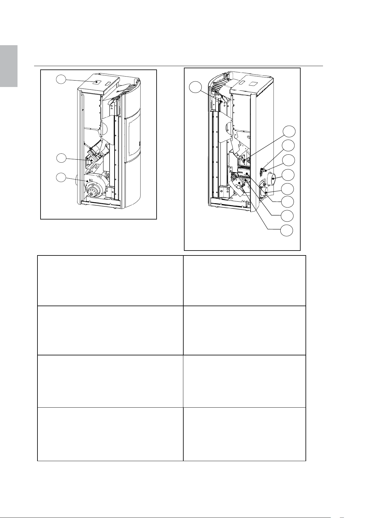
Polly 54 Polly
1
2
3
conne
ction
de / fr / it / en
11.2. Elektro- und Elektronikbestandteile / Eléments électriques et
électroniques / Componenti elettrici ed elettronici / Electrical
and electronic component
4
1…..…Bedienfeld-Display
2…..…Schneckenmotor
3…..…Saugzug
4…..…Feuerraumfühler
5…..…Glühpatrone
6…..…Hauptschalter/Sicherung/Netzanschluss
1…..…tableau de commande
2…..…Moteur de la vis sans fin
3…..…Ventilateur
4…..…Sonde pour le foyer
5…..…Bougie d’allumage
6…..…Interrupteur/sécurité/prise
1…..…Display del pannello comandi
2…..…Motoriduttore
3…..…Presa d'aria
4…..…Sensore camera di combustione
5…..…Candeletta
6…..…Interruttore principale/fusibile/collegamento
1…..…Control panel display
2…..…Screw conveyor motor
3…..…Vacuum exhaust
4…..…Combustion chamber sensor
5…..…Heat cylinder
6…..…Main switch/circuit breaker/mains
7…..…Sicherheitstemperaturbegrenzer
8…..…Abgasstutzen
9….....Luftfilterkasten
10..….Steuerung
11…...Luftmengensensor
12..….Schwenkrostmotor
7…..…Thermostat de sécurité
8…..…Buse pour gaz d’échappement
9….....Boite à filtre à air
10..….Commande
11…...capteur d’air
12..….Moteur de la grille à bascule
7…..…Limitatore della temperatura di
sicurezza
8…..…Raccordi fumi
9….....Scatola filtro aria
10..….Centralina
11…...Sensore aria
7…..…Safety temperature delimiter
8…..…Flue connector
9….....Air filter box
10..….Control unit
11…...Air quantity sensor
12..….Pivoting grate motor
5
6
7
8
9
10
11
12
Page 57
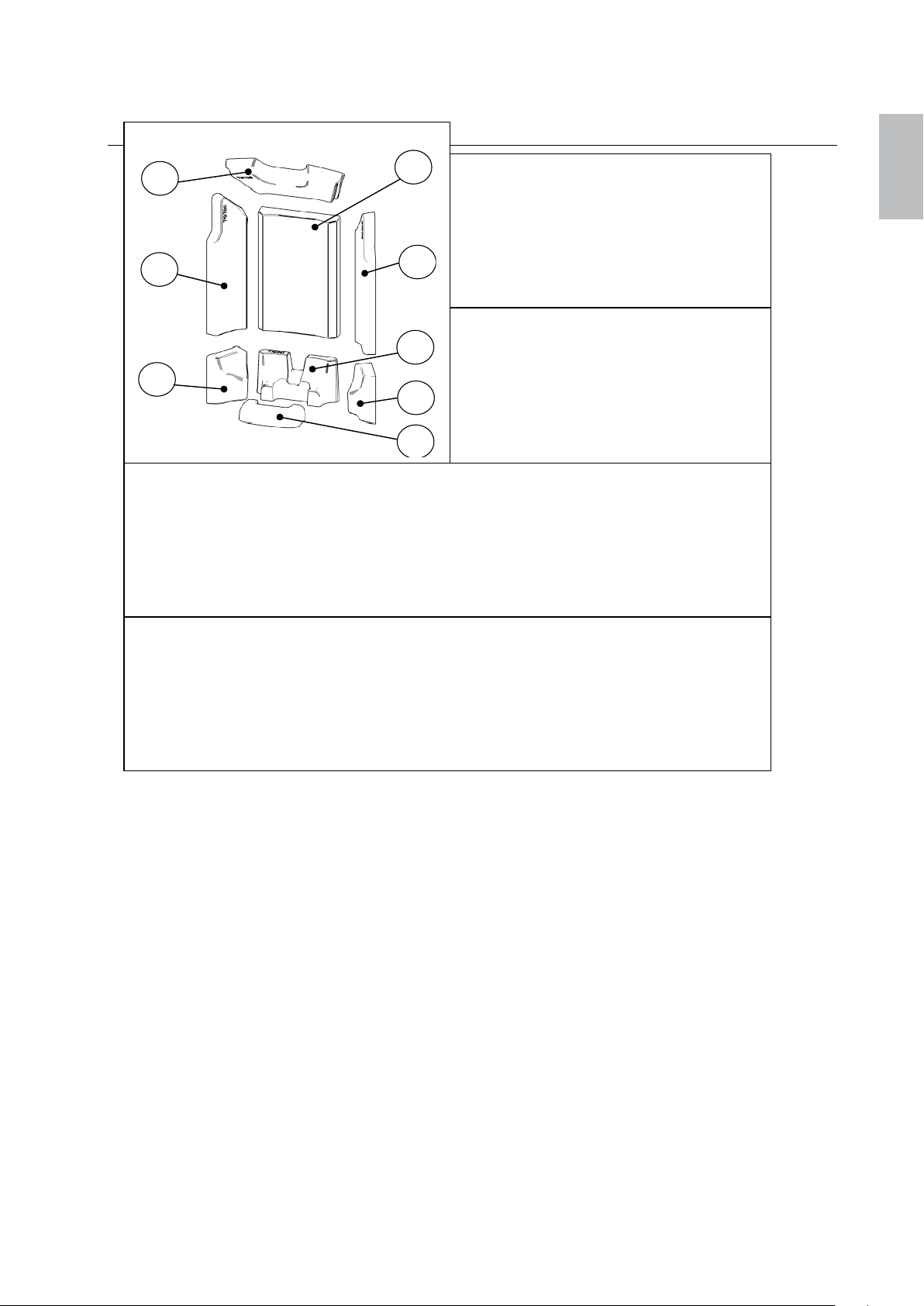
Polly 55 Polly
1
8 6 3 4 2
7
5
8……..Keramott Zugp
latte
8……..Refrattario tagliafiamme
719788
8……..Keramott draft plate
719788
11.3. Feuerraumauskleidung / Revêtement du foyer / Rivestimento
della camera di combustione / Combustion chamber lining
1…..…Keramottboden links 719783
2…..…Keramottboden hinten 719781
3…..…Keramottboden rechts 719784
4…..…Keramottboden vorne 719782
5…..…Keramottwand links 719786
6….....Keramottwand hinten 719785
7…..…Keramottwand rechts 719787
1…..…Refrattario di base sinistra 719783
2…..…Refrattario di base posteriore 719781
3…..…Refrattario di base destra 719784
4…..…Refrattario di base anteriore 719782
5…..…Refrattario laterale sinistra 719786
6…..…Refrattario laterale posteriore 719785
7…..…Refrattario laterale destra 719787
1…..…Keramott du sol gauche 719783
2…..…Keramott du sol arriére 719781
3…..…Keramott du sol droite 719784
4…..…Keramott du sol avant 719782
5…..…Keramott côté gauche 719786
6….....Keramott du fonde 719785
7…..…Keramott côté droit 719787
8……..Keramott Déflecteur 719788
1…..…Keramott bottom left 719783
2…..…Keramott bottom back 719781
3…..…Keramott bottom right 719784
4…..…Keramott bottom front 719782
5…..…Keramott wall left 719786
6…..…Keramott wall back 719785
7…..…Keramott wall right 719787
de / fr / it / en
Page 58
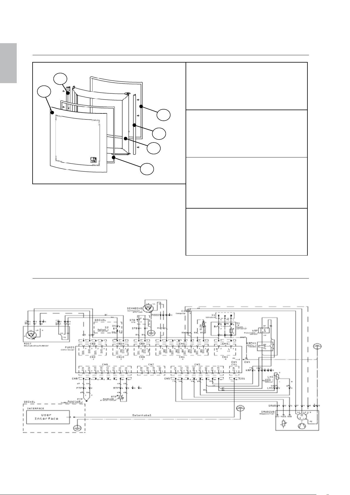
Polly 56 Polly
6…..... Guarnizione oval
e L=2231
de / fr / it / en
11.4. Türbestandteile / Eléments de la porte / Elementi dello sportello
/ Door components
1…..…Türglas 719735
2…..…Flachdichtung L=2300 718438
3…..…Tür geschweißt 719881-29
4…..…Glasleiste links 719886-29
5…..… Glasleiste rechts 719885-29
6…..... Ovaldichtung L=2231 718571
1………Vitre… 719735
2………Joint plat L=2300… 718438
3………Porte soudée...... 719881-29
4………Pareclose gauche 719886-29
5………Pareclose droite 719885-29
6………Joint ovale L=2231 718571
1…..…Vetro 719735
2…..…Guarnizione piatta L=2300
718438
3…..…Sportello saldato 719881-29
4…..…Barra in vetro 719886-29
5…..… Barra in vetro destra 719885-29
1…..…Door glass 719735
2…..…Gasket L=2300 718438
3…..…Welded door 719881-29
4…..…Glass bar left 719886-29
5…..… Glass bar right 719885-29
6…..... Oval seal L=2231 718571
12. Schaltplan / Plan électrique / Schema elettrico / Circuit diagram
Page 59
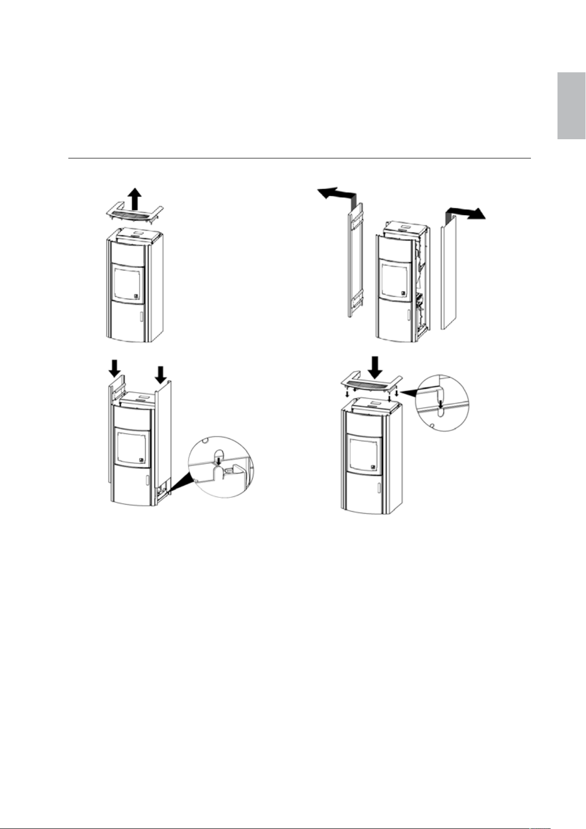
Polly 57 Polly
c)
13. Montagearbeiten am Ofen / Montage sur l’appareil / Montaggio
della stufa / Assembly work on the stove
13.1. Seitenverkleidung und Deckel-Demontage/Montage / Montage et
démontage de l’enveloppe et du couvercle /
Smontaggio/montaggio del rivestimento laterale e del coperchio
/ Side shrouding and cover disassembly/assembly
a)
b)
d)
de / fr / it / en
Page 60
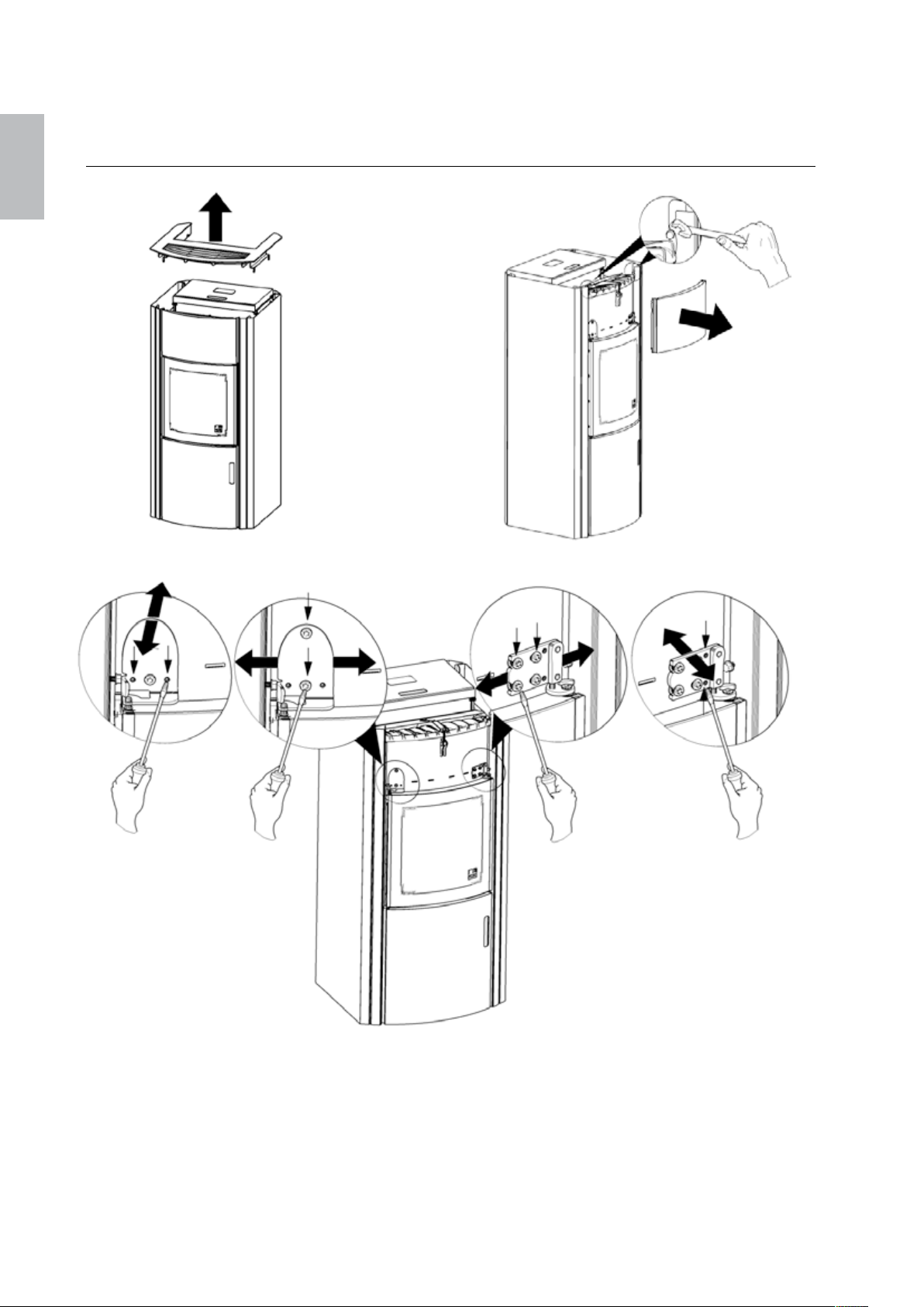
Polly 58 Polly
de / fr / it / en
13.2. Türscharnierjustierung oben / Ajustement des charnières du
a)
haut / Regolazione della cerniera in alto / Upper door hinge
adjustment
c)
b)
Page 61
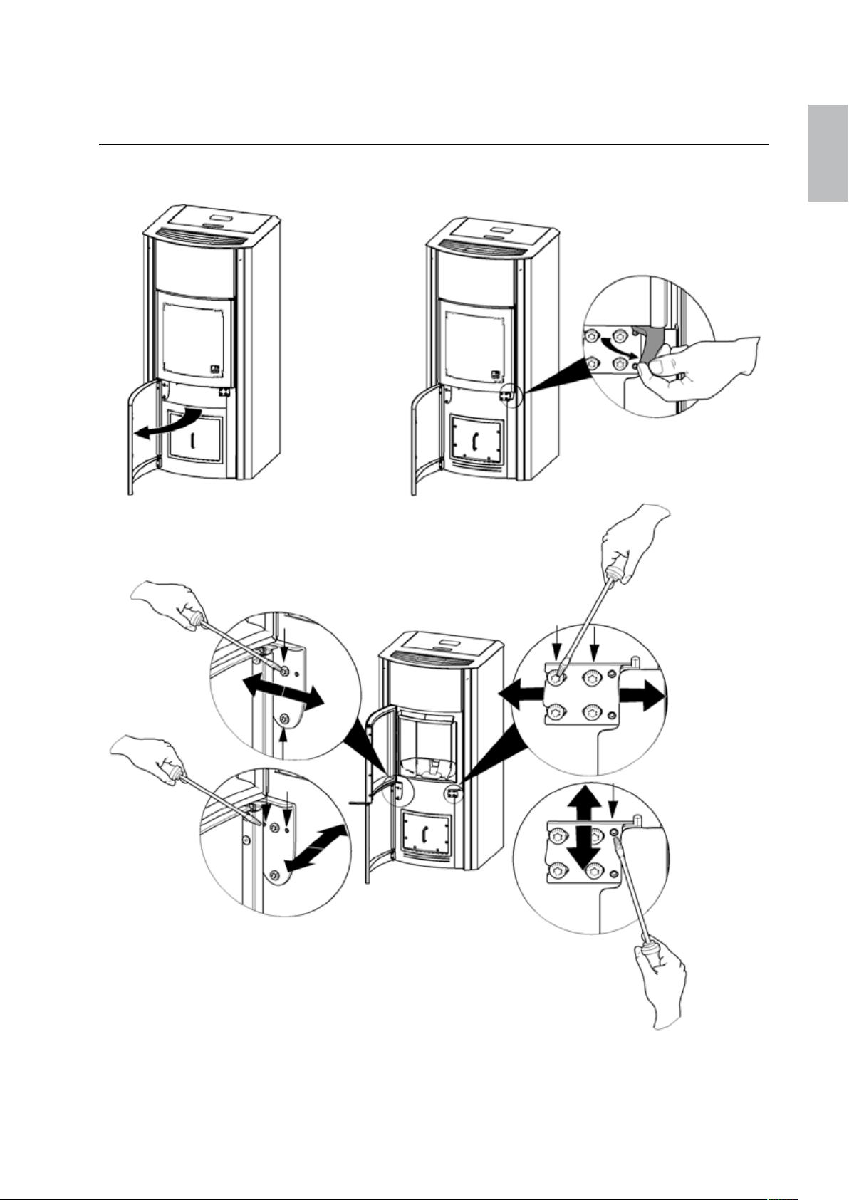
Polly 59 Polly
13.3. Türscharnierjustierung unten / Ajustement des charnières du
bas / Regolazione della cerniera in basso / Lower door hinge
adjustment
a)
c)
b)
de / fr / it / en
Page 62
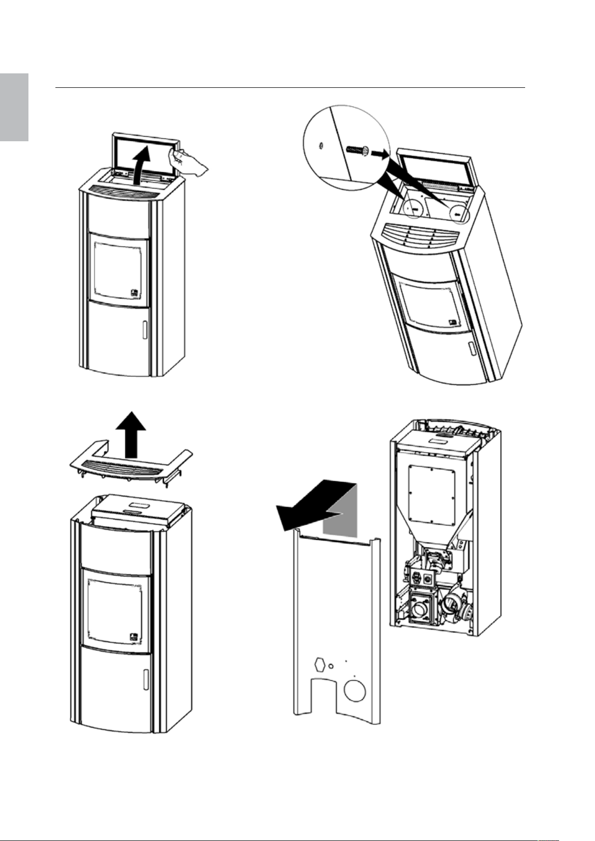
de / fr / it / en
a)
c)
Polly 60 Polly
13.4. Rückwandausbau / Démontage de la paroi arrière / Smontaggio
del pannello posteriore / Rear wall removal
b)
d)
Page 63
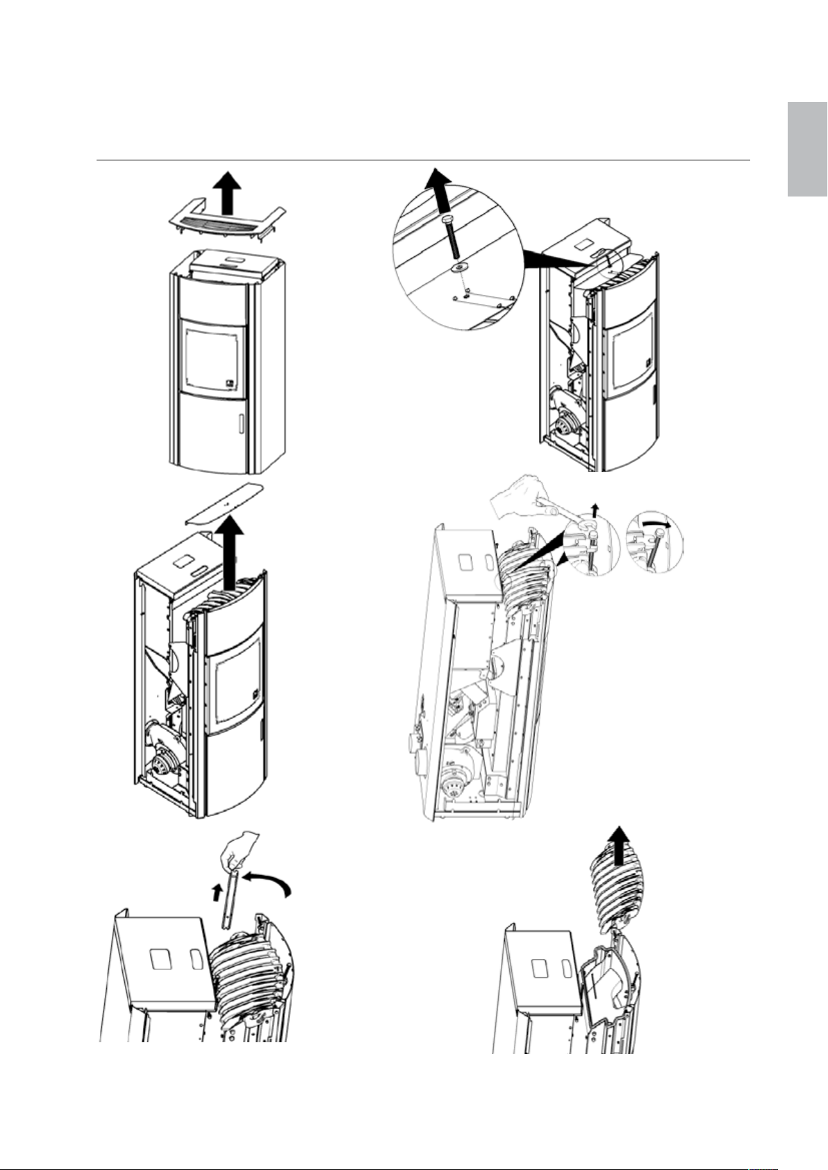
Polly 61 Polly
e)
13.5. Abgasschachtreinigung, Entleerung Aschebox / Nettoyage du
canal des gaz d’échappement, vidange du cendrier / Pulizia del
condotto dei fumi, svuotamento del cassetto raccoglicenere /
Flue gas duct cleaning, emptying of the ash box
b)
a)
c)
d)
f)
de / fr / it / en
Page 64

Polly 62 Polly
de / fr / it / en
g)
i)
k)
nur mit einem trockenen Tuch die groben Beläge entfernen.
Nicht blankpolieren!
Rimuovere solo le incrostazioni grossolane utilizzando un panno
asciutto.
Non pulire a lucido!
Remove the coarse sediment only using a dry cloth.
Do not polish to a shine!
h)
l)
j)
Page 65
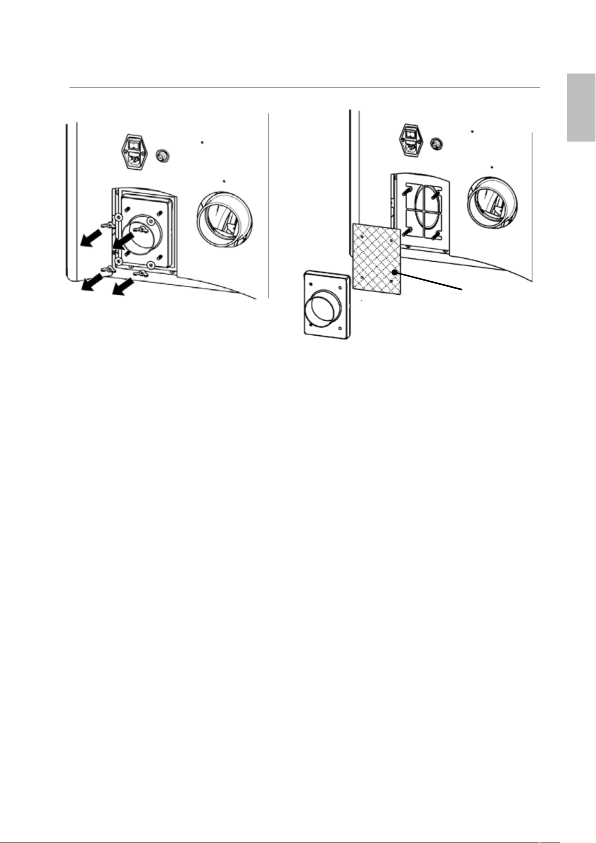
Polly 63 Polly
Filter: (Bedruckung aussen)
Filter: (outer printing)
13.6. Filtertausch / Changer le filtre / Cambio del filtro / Filter
a)
Bezeichnung: Flachfilter mit Anzeige 01446
Hersteller: Vileda
Description: Filtre nr. 01446
Fabricant: Vileda
Specifica: Filtro piatto con codice 01446
Costruttore: Vileda
Designation: Flat filter with the marking 01446
Manufacturer: Vileda
replacement
b)
de / fr / it / en
Filtro: (lato stampato verso
l'esterno)
Page 66
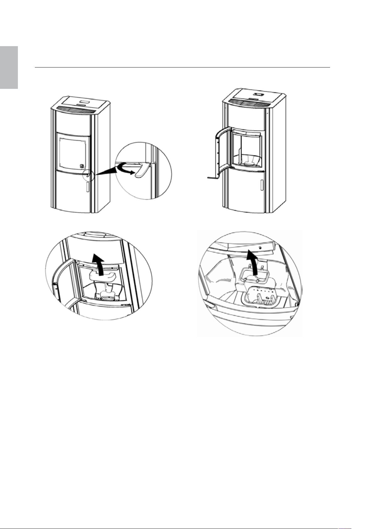
Polly 64 Polly
c) d
)
de / fr / it / en
13.7. Tausch Einlagering Brenntopf / Changer la bague du brazero /
a)
Sostituzione anello a inserimento braciere / Replacement of
burner bowl spacer ring
b)
Page 67

Page 68

Austroflamm GmbH, Austroflamm Platz 1, 4631 Krenglbach, Austria, Stand 10/13
 Loading...