

Page 1

AT&T 585-300-903
Issue 4
October 1992
AUDIX®
Networking
Page 2

Copyright 1992 AT&T
All Rights Reserved
Printed in U.S.A.
Notice
While reasonable efforts were made to ensure that the information
in this document was complete and accurate at the time of printing,
AT&T can assume no responsibility for any errors. Changes and
corrections to the information contained in this document may be
incorporated into future reissues.
Your Responsibility for Your System's Security
You are responsible for the security of your system. AT&T does
not warrant that this product is immune from or will prevent
unauthorized use of common-carrier telecommunication services or
facilities accessed through or connected to it. AT&T will not be
responsible for any charges that result from such unauthorized use.
Product administration to prevent unauthorized use is your
responsibility and your system administrator should read all
documents provided with this product to fully understand the
features available that may reduce your risk of incurring charges.
Federal Communications Commission Statement
Part 15: Class A Statement.
tested and found to comply with the limits for a Class A digital
device, pursuant to Part 15 of the FCC Rules. These limits are
designed to provide reasonable protection against harmful
interference when the equipment is operated in a commercial
environment. This equipment generates, uses, and can radiate
radio-frequency energy and, if not installed and used in accordance
with the instruction manual, may cause interference to radio
communications. Operation of this equipment in a residential area
is likely to cause interference, in which case the user at his/her own
expense will be required to take whatever measures may be
requiured to correct the interference.
This equipment has been
Trademarks
DEFINITY® is a registered trademark of AT&T.
AUDIX® is a registered trademark of AT&T.
Refer to the
of this manual for additional trademarks.
Trademarks and Service Marks
section near the front
Ordering Information
The ordering number for this document is
585-300-903. To order this document, call the AT&T
Customer Information Center at 1-800-432-6600 (In Canada,
use 1-800-255-1242). For more information about AT&T
documents, refer to the
Systems Publications Catalog
Business Communications
(555-000-010).
Comments
To comment on this document, return the comment
card at the front of the document.
Acknowledgment
This document was prepared by the BCSystems Product
Documentation Development Department in Denver, CO.
Part 68: Network Registration Number. This equipment
is registered with the FCC in accordance with Part 68 of the FCC
Rules. It is identified by FCC registration number AS593M-14695MA-E.
Page 3

________________________________________________________________________
Contents
________________________________________________________________________
________________________________________________________________________
About This Document . . . . . . . . . . . . . . . . . . . . xvii
INTENDED AUDIENCE . . . . . . . . . . . . . . . . . . xvii
PREREQUISITE SKILLS OR KNOWLEDGE . . . . . . . . . . . . xvii
HOW THIS DOCUMENT IS ORGANIZED . . . . . . . . . . . . . xvii
CHANGES FROM THE PREVIOUS ISSUE . . . . . . . . . . . . xviii
CONVENTIONS USED IN THIS DOCUMENT . . . . . . . . . . . xix
TRADEMARKS AND SERVICE MARKS . . . . . . . . . . . . . xix
RELATED RESOURCES . . . . . . . . . . . . . . . . . . xx
HOW TO MAKE COMMENTS ABOUT THIS DOCUMENT . . . . . . . xx
1. Introduction . . . . . . . . . . . . . . . . . . . . . . 1-1
THE NETWORK INTERFACE . . . . . . . . . . . . . . . . 1-1
LOCAL NETWORKING . . . . . . . . . . . . . . . . . . . 1-2
REMOTE NETWORKING . . . . . . . . . . . . . . . . . . 1-3
NETWORK PLANNING . . . . . . . . . . . . . . . . . . . 1-3
AUDIX NETWORK IMPLEMENTATION . . . . . . . . . . . . . 1-3
AUDIX Software . . . . . . . . . . . . . . . . . . . . 1-4
ACC/ACCE . . . . . . . . . . . . . . . . . . . . . 1-4
Other AUDIX Circuit Pack Requirements . . . . . . . . . . . . 1-6
Rear Connector Panel and Backplane . . . . . . . . . . . . 1-6
Network Cabling Common to Most Configurations . . . . . . . . . 1-7
AUDIX System Administration . . . . . . . . . . . . . . . 1-11
NETWORKING ENHANCEMENTS . . . . . . . . . . . . . . . 1-11
R1V5 Release . . . . . . . . . . . . . . . . . . . . 1-11
R1V6 Release . . . . . . . . . . . . . . . . . . . . 1-12
R1V7 Release . . . . . . . . . . . . . . . . . . . . 1-12
iii
Page 4

iv Contents
________________________________________________________________________________________________
________________________________________________________________________________________________
________________________________________________________________________________________________
2. Dedicated EIA RS-232 Networks . . . . . . . . . . . . . . 2-1
CONSIDERATIONS . . . . . . . . . . . . . . . . . . . . 2-1
GENERAL INFORMATION . . . . . . . . . . . . . . . . . 2-1
AUDIX REQUIREMENTS FOR DEDICATED RS-232 . . . . . . . . . 2-4
SWITCH (OR CUSTOMER) REQUIREMENTS FOR DEDICATED RS-
232 . . . . . . . . . . . . . . . . . . . . . . . . . 2-5
DATA RATES FOR DEDICATED RS-232 . . . . . . . . . . . . . 2-5
3. Switched EIA RS-232 Networks . . . . . . . . . . . . . . 3-1
CONSIDERATIONS . . . . . . . . . . . . . . . . . . . . 3-1
SWITCHED RS-232 USING MODEMS . . . . . . . . . . . . . 3-2
AUDIX System Requirements For Switched RS-232 Using
Modems . . . . . . . . . . . . . . . . . . . . . . 3-4
Switch (or Customer) Requirements For Switched RS-232 Using
Modems . . . . . . . . . . . . . . . . . . . . . . 3-4
Data Rates for Switched RS-232 Using Modems . . . . . . . . . 3-6
SWITCHED RS-232 USING DATA MODULES FOR DCP . . . . . . . 3-7
AUDIX System Requirements for Switched RS-232 Using Data Modules
For DCP . . . . . . . . . . . . . . . . . . . . . . 3-8
Switch (or Customer) Requirements for Switched RS-232 Using Data
Modules for DCP . . . . . . . . . . . . . . . . . . . 3-8
Data Rates for Switched RS-232 Using Data Modules For
DCP . . . . . . . . . . . . . . . . . . . . . . . 3-8
4. DCP Mode 1 Networks — 56 Kbps . . . . . . . . . . . . . 4-1
CONSIDERATIONS . . . . . . . . . . . . . . . . . . . . 4-1
GENERAL INFORMATION . . . . . . . . . . . . . . . . . 4-2
Static Access . . . . . . . . . . . . . . . . . . . . . 4-4
Dynamic Access . . . . . . . . . . . . . . . . . . . . 4-4
AUDIX SYSTEM REQUIREMENTS FOR DCP MODE 1 . . . . . . . . 4-5
SWITCH (OR CUSTOMER) REQUIREMENTS FOR DCP MODE
1 . . . . . . . . . . . . . . . . . . . . . . . . . . 4-6
Static Access Switch Requirements . . . . . . . . . . . . . 4-6
Dynamic Access Switch Requirements . . . . . . . . . . . . 4-7
Page 5

_ ______________________________________________________________________________________
_ ______________________________________________________________________________________
_ ______________________________________________________________________________________
DATA RATES FOR DCP MODE 1 . . . . . . . . . . . . . . . 4-7
Contents v
5. DCP Mode 2 Networks — Modem Pooling . . . . . . . . . . 5-1
CONSIDERATIONS . . . . . . . . . . . . . . . . . . . . 5-1
GENERAL INFORMATION . . . . . . . . . . . . . . . . . 5-2
AUDIX SYSTEM REQUIREMENTS FOR DCP MODE 2 . . . . . . . . 5-5
SWITCH (OR CUSTOMER) REQUIREMENTS FOR DCP MODE
2 . . . . . . . . . . . . . . . . . . . . . . . . . . 5-5
Basic Switch Needs . . . . . . . . . . . . . . . . . . 5-6
DCP Interface for the AUDIX Network Channels . . . . . . . . . 5-6
DCP Interface for the Digital Side of the Modem Pool . . . . . . . 5-7
Analog (Tip and Ring) Interface to the Interlocation Facilities . . . . . 5-7
Analog Interface for the Analog Side of the Modem Pool . . . . . . 5-7
Modems and Data Modules . . . . . . . . . . . . . . . . 5-8
Rack-Mount Equipment . . . . . . . . . . . . . . . . . 5-11
Cabling . . . . . . . . . . . . . . . . . . . . . . . 5-11
DATA RATES FOR DCP MODE 2 . . . . . . . . . . . . . . . 5-11
DCP MODE 2 FOR A 5ESS SWITCH . . . . . . . . . . . . . . 5-11
6. DCP Mode 3 Networks — 64 Kbps . . . . . . . . . . . . . 6-1
CONSIDERATIONS . . . . . . . . . . . . . . . . . . . . 6-1
GENERAL INFORMATION . . . . . . . . . . . . . . . . . 6-2
AUDIX SYSTEM REQUIREMENTS FOR DCP MODE 3 . . . . . . . . 6-2
SWITCH (OR CUSTOMER) REQUIREMENTS FOR DCP MODE
3 . . . . . . . . . . . . . . . . . . . . . . . . . . 6-4
Colocated Requirements . . . . . . . . . . . . . . . . . 6-4
Interlocation Requirements . . . . . . . . . . . . . . . . 6-5
DATA RATES FOR DCP MODE 3 . . . . . . . . . . . . . . . 6-6
DCP MODE 3 FOR A 5ESS SWITCH . . . . . . . . . . . . . . 6-7
Page 6

vi Contents
________________________________________________________________________________________________
________________________________________________________________________________________________
________________________________________________________________________________________________
7. Mixtures of RS-232 and DCP Networks . . . . . . . . . . . 7-1
CONSIDERATIONS . . . . . . . . . . . . . . . . . . . . 7-1
RS-232 AND DCP AT THE SAME AUDIX SYSTEM . . . . . . . . . 7-1
RS-232 AND DCP AT SEPARATE LOCATIONS . . . . . . . . . . 7-2
8. EIA RS-232 Cabling . . . . . . . . . . . . . . . . . . . 8-1
DEDICATED RS-232 CABLING . . . . . . . . . . . . . . . . 8-1
SWITCHED RS-232 CABLING . . . . . . . . . . . . . . . . 8-4
DIP Switch Settings . . . . . . . . . . . . . . . . . . 8-7
Mixing Modem Types and Modes . . . . . . . . . . . . . . 8-7
RS-232 to DCP Conversion . . . . . . . . . . . . . . . . 8-8
SWITCH ADMINISTRATION . . . . . . . . . . . . . . . . . 8-9
9. DCP Cabling and Administration . . . . . . . . . . . . . 9-1
ACC(E) WIRING TO THE SWITCH . . . . . . . . . . . . . . . 9-1
System 75, System 85, and DEFINITY Communications
Systems . . . . . . . . . . . . . . . . . . . . . . 9-1
Non-DCP Switch Applications . . . . . . . . . . . . . . . 9-2
SWITCH ADMINISTRATION . . . . . . . . . . . . . . . . . 9-5
System 75, Generic 1, and Generic 3 Administration . . . . . . . . 9-5
System 85 Administration . . . . . . . . . . . . . . . . . 9-6
Generic 2 Administration . . . . . . . . . . . . . . . . . 9-9
10. DCP Mode 1 Installation and Administration . . . . . . . . . 10-1
SWITCH COMPONENT INSTALLATION . . . . . . . . . . . . . 10-1
SWITCH ADMINISTRATION . . . . . . . . . . . . . . . . . 10-1
4ESS Administration . . . . . . . . . . . . . . . . . . 10-1
System 75, Generic 1, and Generic 3 Administration . . . . . . . . 10-2
System 85 Administration . . . . . . . . . . . . . . . . . 10-3
Generic 2 Administration . . . . . . . . . . . . . . . . . 10-4
LOOPBACK TESTING . . . . . . . . . . . . . . . . . . . 10-7
Page 7

_ ______________________________________________________________________________________
_ ______________________________________________________________________________________
_ ______________________________________________________________________________________
Loopback Testing for R1V7 . . . . . . . . . . . . . . . . 10-7
Loopback Testing for R1V5 and R1V6 . . . . . . . . . . . . 10-8
Contents vii
11. DCP Mode 2 Installation and Administration . . . . . . . . . 11-1
INSTALLING A 2296A AND MTDM IN A MODEM POOL . . . . . . . . 11-1
Install the Modem Pool Cabinet . . . . . . . . . . . . . . . 11-1
Install the Multiple Mountings . . . . . . . . . . . . . . . 11-1
Install the Modems and Data Sets . . . . . . . . . . . . . . 11-2
Install the Multi-Mount Cables . . . . . . . . . . . . . . . 11-6
Install the MTDM and 2296A Cables . . . . . . . . . . . . . 11-9
2296A Option Settings (D-Lead Modem Pool) . . . . . . . . . . 11-9
INSTALLING A 7400A IN A MODEM POOL . . . . . . . . . . . . 11-11
INSTALLING STAND-ALONE MODEM POOLS . . . . . . . . . . . 11-14
System 75/85, System 75 XE, Generic 1, Generic 2, and Generic
3 . . . . . . . . . . . . . . . . . . . . . . . . . 11-14
ADMINISTERING THE SWITCH FOR MODEM POOLING . . . . . . . 11-20
System 75, Generic 1, and Generic 3 Administration . . . . . . . . 11-20
System 85 Administration . . . . . . . . . . . . . . . . . 11-21
Modem Pooling Testing . . . . . . . . . . . . . . . . . 11-23
Generic 2 Administration . . . . . . . . . . . . . . . . . 11-24
12. DCP Mode 3 Installation and Administration . . . . . . . . . 12-1
SWITCH COMPONENT INSTALLATION . . . . . . . . . . . . . 12-1
SWITCH ADMINISTRATION . . . . . . . . . . . . . . . . . 12-1
System 75, Generic 1, and Generic 3 Administration . . . . . . . . 12-1
System 85 Administration . . . . . . . . . . . . . . . . . 12-2
Generic 2 Administration . . . . . . . . . . . . . . . . . 12-2
LOOPBACK TESTING FOR INTERLOCATED SYSTEMS . . . . . . . 12-4
Page 8

viii Contents
________________________________________________________________________________________________
________________________________________________________________________________________________
________________________________________________________________________________________________
13. AUDIX System Administration . . . . . . . . . . . . . . 13-1
REMOTE UPDATES . . . . . . . . . . . . . . . . . . . 13-1
Partial Updates . . . . . . . . . . . . . . . . . . . . 13-1
Complete Updates . . . . . . . . . . . . . . . . . . . 13-2
Network Turnaround . . . . . . . . . . . . . . . . . . 13-2
SYSTEM PROFILES . . . . . . . . . . . . . . . . . . . 13-3
SETTING UP THE LOCAL AUDIX SYSTEM PROFILE . . . . . . . . 13-3
Form Fields . . . . . . . . . . . . . . . . . . . . . 13-4
Saving Local System Data . . . . . . . . . . . . . . . . 13-10
SETTING UP A REMOTE AUDIX SYSTEM PROFILE . . . . . . . . . 13-10
Form Fields . . . . . . . . . . . . . . . . . . . . . 13-11
Saving Remote System Data . . . . . . . . . . . . . . . 13-16
RECORDING AUDIX MACHINE NAMES . . . . . . . . . . . . . 13-17
ADMINISTERING PORTS . . . . . . . . . . . . . . . . . . 13-18
Form Fields . . . . . . . . . . . . . . . . . . . . . 13-19
Saving Data . . . . . . . . . . . . . . . . . . . . . 13-21
ADMINISTERING SYSTEM LIMITS . . . . . . . . . . . . . . . 13-22
Form Fields . . . . . . . . . . . . . . . . . . . . . 13-22
Calculating Filesystem Sizes . . . . . . . . . . . . . . . 13-22
Comparing the Recommended File Sizes to Actual Sizes . . . . . . 13-24
Increasing the Size of a Filesystem . . . . . . . . . . . . . 13-24
MOVING A SUBSCRIBER BETWEEN AUDIX SYSTEMS IN A
NETWORK . . . . . . . . . . . . . . . . . . . . . . . 13-25
ADMINISTRATOR’S WORKSHEET . . . . . . . . . . . . . . 13-27
14. AUDIX Network Testing . . . . . . . . . . . . . . . . . 14-1
TESTING THE NETWORK CONNECTIONS . . . . . . . . . . . . 14-4
Step 1: Performing Remote Connection Tests . . . . . . . . . . 14-4
Step 2: Performing Loop-Around Tests . . . . . . . . . . . . 14-15
Step 3: Performing Channel or Modem Loop-Around Tests . . . . . . 14-25
Step 3A: Channel Internal Loop-Around Test . . . . . . . . . . 14-25
Step 3B: Modem Loop-Around Test . . . . . . . . . . . . . 14-25
SETTING UP REMOTE UPDATES . . . . . . . . . . . . . . . 14-26
Page 9

_ ______________________________________________________________________________________
_ ______________________________________________________________________________________
_ ______________________________________________________________________________________
Step 1: Activating the Remote Updates Feature . . . . . . . . . 14-26
Step 2: Testing the Remote Updates Feature . . . . . . . . . . 14-26
Step 3: Performing Voice Mail Test . . . . . . . . . . . . . 14-27
Step 4: Activating Remote Updates for Additional AUDIX
Systems . . . . . . . . . . . . . . . . . . . . . . 14-28
CHECKING ADMINISTRATION LOG ENTRIES . . . . . . . . . . . 14-29
TROUBLESHOOTING THE NETWORK . . . . . . . . . . . . . 14-30
Contents ix
A. Network Considerations . . . . . . . . . . . . . . . . . A-1
BCSDC CONSIDERATIONS . . . . . . . . . . . . . . . . . A-1
AUDIX NETWORK PLANNING WORKSHEET . . . . . . . . . . . A-4
B. Sales Engineering Notes . . . . . . . . . . . . . . . . . B-1
BASIC AUDIX AND MISCELLANEOUS AUDIX FEATURES . . . . . . . B-1
DCS NETWORKS AND AUDIX . . . . . . . . . . . . . . . . B-1
ENGINEERING WORKSHEETS . . . . . . . . . . . . . . . . B-1
QUALITY PROTECTION PLAN CHANGE NOTICE (QPPCN) . . . . . . B-1
UPGRADES, SOFTWARE, AND VINTAGES . . . . . . . . . . . B-2
C. AMIS Analog Networking . . . . . . . . . . . . . . . . . C-1
Abbreviations . . . . . . . . . . . . . . . . . . . . . . . AB-1
Glossary . . . . . . . . . . . . . . . . . . . . . . . . . GL-1
Page 10

x Contents
________________________________________________________________________________________________
________________________________________________________________________________________________
________________________________________________________________________________________________
Index . . . . . . . . . . . . . . . . . . . . . . . . . . . IN-1
Page 11

_ ______________________________________________________________________________________
_ ______________________________________________________________________________________
_ ______________________________________________________________________________________
Contents xi
LIST OF FIGURES
Figure 1-1. H600-330, Group 1 AUDIX Special Null-Modem Cable . . . . . . . 1-8
Figure 1-2. H600-331, Group 2 AUDIX Networking Breakout Cable . . . . . . . 1-9
Figure 1-3. H600-331, Group 1 AUDIX Networking Breakout Cable . . . . . . . 1-10
Figure 2-1. Dedicated RS-232 Network of Two AUDIX Systems . . . . . . . . 2-2
Figure 2-2. Dedicated RS-232 Network of Two AUDIX Systems and a PC (Low Traffic
Only) . . . . . . . . . . . . . . . . . . . . . . . . . . 2-3
Figure 2-3. Dedicated RS-232 Network of Three AUDIX Systems (Low Traffic
Only) . . . . . . . . . . . . . . . . . . . . . . . . . . 2-3
Figure 2-4. Dedicated RS-232 Network of Three AUDIX Systems and a
PC . . . . . . . . . . . . . . . . . . . . . . . . . . 2-4
Figure 2-5. Dedicated RS-232 Extended Connections . . . . . . . . . . . 2-6
Figure 3-1. Dedicated and Switched RS-232 Network for a Single Switch . . . . . 3-3
Figure 3-2. Switched RS-232 Network for a Single Switch . . . . . . . . . . 3-4
Figure 3-3. Switched RS-232 Network for Separate Locations . . . . . . . . . 3-5
Figure 3-4. Switched RS-232 Network for Separate Locations and a PC . . . . . 3-6
Figure 3-5. Converting RS-232 Channels to DCP . . . . . . . . . . . . . 3-7
Figure 4-1. DCP Mode 1 Network Using Switched 56 Service . . . . . . . . . 4-3
Figure 4-2. PC Added to a DCP Network . . . . . . . . . . . . . . . . 4-5
Figure 5-1. Typical Rack-Mounted Modem Pool Using D-Lead Control . . . . . . 5-2
Figure 5-2. Typical Stand-Alone Modem Pool (No D-Lead Control) . . . . . . . 5-3
Figure 5-3. DCP Mode 2 Network (Modem Pooling) . . . . . . . . . . . . 5-4
Figure 6-1. DCP Mode 3 Network for a Single Switch . . . . . . . . . . . 6-3
Figure 6-2. DCP Mode 3 Network for a Non-DCP Switch . . . . . . . . . . 6-4
Figure 6-3. DCP Mode 3 Network for Multiple Locations . . . . . . . . . . . 6-6
Figure 6-4. DCP Mode 3 Network for a 5ESS Switch . . . . . . . . . . . . 6-7
Figure 7-1. RS-232 and DCP at the Same AUDIX . . . . . . . . . . . . . 7-2
Figure 7-2. High-Speed Switched RS-232 and DCP AUDIX Connections . . . . . 7-3
Figure 7-3. Using DCP for AUDIX Systems and RS-232 for a PC . . . . . . . . 7-4
Figure 7-4. RS-232 and DCP at Separate Locations . . . . . . . . . . . . 7-5
Figure 8-1. Dedicated RS-232 Connection (within 10 feet) . . . . . . . . . . 8-2
Figure 8-2. Dedicated RS-232 Connection (within 50 feet) . . . . . . . . . . 8-3
Page 12

xii Contents
________________________________________________________________________________________________
________________________________________________________________________________________________
________________________________________________________________________________________________
Figure 8-3. Dedicated RS-232 Connection (using Z3A ADUs) . . . . . . . . . 8-4
Figure 8-4. Switched RS-232 to an Analog Switch Port . . . . . . . . . . . 8-5
Figure 8-5. Switched RS-232 to a DCP Switch Port . . . . . . . . . . . . 8-5
Figure 9-1. DCP Cabling to the Switch Using the H600-331, Group 2
Cable . . . . . . . . . . . . . . . . . . . . . . . . . . 9-2
Figure 9-2. MERLIN II Default Configuration and Slot Assignments . . . . . . . 9-3
Figure 9-3. AUDIX to MERLIN II Connectivity . . . . . . . . . . . . . . 9-4
Figure 9-4. Manager II Administration of DCP Port (Proc 000, Word 1) . . . . . . 9-10
Figure 9-5. Manager II Administration of DCP Port (Proc 000, Word 3) . . . . . . 9-11
Figure 9-6. Manager II Administration of DCP Port (Proc 014, Word 1) . . . . . . 9-12
Figure 9-7. Manager II Administration of DCP Port (Proc 014, Word 2) . . . . . . 9-13
Figure 9-8. Manager II Administration for DCP Ports (Proc 051, Word 1) . . . . . 9-14
Figure 9-9. Manager II Administration for DCP Ports (Proc 052, Word 1) . . . . . 9-15
Figure 10-1. Manager II Mode 1 Administration (Proc 100, Word 1) . . . . . . . 10-4
Figure 10-2. Manager II Mode 1 Administration (Proc 100, Word 2) . . . . . . . 10-5
Figure 10-3. Manager II Mode 1 Administration (Proc 101, Word 1) . . . . . . . 10-6
Figure 10-4. 56 Kbps Network Loop-Around Test . . . . . . . . . . . . . 10-8
Figure 10-5. V.35 Male Connector . . . . . . . . . . . . . . . . . . 10-9
Figure 10-6. Loopback Test with the H600-331, Group 2 Cable . . . . . . . . 10-11
Figure 10-7. Loopback Test with the H600-331, Group 1 Cable . . . . . . . . 10-12
Figure 11-1. 72-Inch Data Cabinet and Multiple Mountings . . . . . . . . . . 11-2
Figure 11-2. Modem Pooling Cabinet with MTDMs (Front View) . . . . . . . . 11-3
Figure 11-3. MTDM Location of TRIC 4 Chips . . . . . . . . . . . . . . 11-5
Figure 11-4. Modem Pooling Cabinet Cabling . . . . . . . . . . . . . . 11-7
Figure 11-5. Modem Pooling Cabinet with 7400As Front View . . . . . . . . 11-10
Figure 11-6. AUDIX Networking (Modem Pooling) with 7400A DSUs . . . . . . 11-13
Figure 11-7. Analog Network Using Stand-Alone Modems and Data Sets . . . . . 11-14
Figure 11-8. System 75, Generic 1, and Generic 3 Modem Pool
Assignments . . . . . . . . . . . . . . . . . . . . . . . 11-21
Figure 11-9. Manager II Administration for Digital Side of Modem Pooling (Proc 100,
Word 1) . . . . . . . . . . . . . . . . . . . . . . . . . 11-24
Figure 11-10. Manager II Administration for Digital Side of Modem Pooling (Proc 100,
Word 2) . . . . . . . . . . . . . . . . . . . . . . . . . 11-25
Figure 11-11. Manager II Administration for Digital Side of Modem Pooling (Proc 014,
Word 1) . . . . . . . . . . . . . . . . . . . . . . . . . 11-26
Page 13

_ ______________________________________________________________________________________
_ ______________________________________________________________________________________
_ ______________________________________________________________________________________
Contents xiii
Figure 11-12. Manager II Administration for Digital Side of Modem Pooling (Proc 014,
Word 2) . . . . . . . . . . . . . . . . . . . . . . . . . 11-27
Figure 11-13. Manager II Administration for Analog Side of Modem Pooling (Proc 100,
Word 1) . . . . . . . . . . . . . . . . . . . . . . . . . 11-28
Figure 11-14. Manager II Administration for Analog Side of Modem Pooling (Proc 100,
Word 2) . . . . . . . . . . . . . . . . . . . . . . . . . 11-29
Figure 11-15. Manager II Administration for Modem Pool Pair (Proc 180, Word
1) . . . . . . . . . . . . . . . . . . . . . . . . . . . 11-30
Figure 12-1. Manager II Mode 3 Administration (Proc 100, Word 2) . . . . . . . 12-3
Figure 12-2. 64 Kbps Network Loop-Around Test . . . . . . . . . . . . . 12-5
Figure 13-1. Local AUDIX System Profile . . . . . . . . . . . . . . . 13-4
Figure 13-2. Remote AUDIX System Profile . . . . . . . . . . . . . . . 13-10
Figure 13-3. The Network Port Form . . . . . . . . . . . . . . . . . 13-18
Figure 13-4. The System Limits Form . . . . . . . . . . . . . . . . . 13-23
Figure 14-1. The Maintenance Network Form (R1V3 and R1V4) . . . . . . . . 14-2
Figure 14-2. The Maintenance Network Form (R1V5) . . . . . . . . . . . 14-2
Figure 14-3. The Maintenance Network Form (R1V6) . . . . . . . . . . . 14-3
Figure 14-4. The Maintenance Network Form (R1V7) . . . . . . . . . . . 14-3
Figure 14-5. Remote Connection Test (Digital Path to Another AUDIX
system) . . . . . . . . . . . . . . . . . . . . . . . . . 14-5
Figure 14-6. Remote Connection Test (Analog Path to Another AUDIX
system) . . . . . . . . . . . . . . . . . . . . . . . . . 14-6
Figure 14-7. Remote Connection Test (Colocated AUDIX system) . . . . . . . 14-7
Figure 14-8. Remote Connection Test (RS-232 to Tip/Ring) . . . . . . . . . 14-9
Figure 14-9. Remote Connection Test (RS-232 Colocated AUDIX system) . . . . 14-10
Figure 14-10. Remote Connection Test (RS-232 Converted to DCP) . . . . . . 14-12
Figure 14-11. Remote Connection Test (RS-232 Direct) . . . . . . . . . . . 14-14
Figure 14-12. Near End Connection Test (CO DCP Digital Loop-Around) . . . . . 14-16
Figure 14-13. Near End Connection Test (CO DCP Analog Loop-Around) . . . . . 14-17
Figure 14-14. Near End Connection Test (CO RS-232 Analog Loop-
Around) . . . . . . . . . . . . . . . . . . . . . . . . . 14-18
Figure 14-15. Local Connection Test (DCP) . . . . . . . . . . . . . . . 14-20
Figure 14-16. Local Connection Test (Switched RS-232) . . . . . . . . . . 14-21
Figure 14-17. Local Connection Test (Dedicated RS-232) . . . . . . . . . . 14-22
Figure 14-18. 56/64 Kbps Network Loop-Around Test . . . . . . . . . . . 14-24
Figure 14-19. Checking the ACC(E) Board Status . . . . . . . . . . . . . 14-31
Page 14

xiv Contents
________________________________________________________________________________________________
________________________________________________________________________________________________
________________________________________________________________________________________________
Figure 14-20. Checking the ACC(E) Channel Status . . . . . . . . . . . . 14-32
Figure 14-21. Checking the ACC(E) Channel Status . . . . . . . . . . . . 14-33
Figure 14-22. Checking the AUDIX Listen Status . . . . . . . . . . . . . 14-34
Figure 14-23. Local Connection Test . . . . . . . . . . . . . . . . . 14-35
Figure 14-24. Local Connection Failure . . . . . . . . . . . . . . . . 14-36
Figure 14-25. Near End Connection Test and Failure . . . . . . . . . . . . 14-37
Figure 14-26. Remote Connection Test . . . . . . . . . . . . . . . . 14-38
Figure 14-27. Remote Connection Failure . . . . . . . . . . . . . . . 14-39
Figure A-1. Trunking Requirements in an AUDIX Network . . . . . . . . . . A-3
Figure A-2. AUDIX Networking Worksheet . . . . . . . . . . . . . . . A-5
Figure A-3. Address Ranges When Dealing with a DCS Environment . . . . . . A-7
Page 15

_ ______________________________________________________________________________________
_ ______________________________________________________________________________________
_ ______________________________________________________________________________________
Contents xv
LIST OF TABLES
Table 1-1. Pin Assignments for the H600-331, Group 2 Cable . . . . . . . . . 1-8
Table 1-2. Pin Assignments for the H600-331, Group 1 Cable . . . . . . . . . 1-10
Table 5-1. Tested RS-232 to Rack-Mounted Modem Pool Combinations . . . . . 5-9
Table 5-2. Tested RS-232 to Standalone Modem Pool Combinations . . . . . . 5-10
Table 8-1. MPDM/M1* Option Settings . . . . . . . . . . . . . . . . 8-9
Table 11-1. 7400A Settings for Modem Pool (9600 bps) . . . . . . . . . . . 11-12
Table 13-1. Sample Administrator Worksheet for AUDIX Networking . . . . . . 13-27
Table 13-2. Blank Administrator Worksheet for AUDIX Networking . . . . . . . 13-28
Page 16

xvi Contents
________________________________________________________________________________________________
________________________________________________________________________________________________
________________________________________________________________________________________________
Page 17

_ ______________________________________________________________________________________
About This Document
_ ______________________________________________________________________________________
_ ______________________________________________________________________________________
This document describes most major aspects of networking AUDIX Voice Messaging Systems. Its
purpose is to assist any group or person involved with the implementation of an AUDIX network. If it does
not contain the information you desire, please fill out the feedback form with your comments and send it to
the originating organization.
INTENDED AUDIENCE
This document is intended for account teams, the Business Communications Systems Design Center
(BCSDC), the Technical Service Center (TSC), the Sales and Technical Response Center (STRC), field
technicians, and hotline personnel.
PREREQUISITE SKILLS OR KNOWLEDGE
No prerequisite skills or knowledge are presumed. However, it is recommended that someone with
networking experience be available to assist anyone that is new to this type of implementation.
HOW THIS DOCUMENT IS ORGANIZED
Information in this document is organized as follows.
• Chapter 1, Introduction, describes the network interfaces, an overview of how a network is
implemented, and the AUDIX system requirements that pertain to any type of AUDIX network.
• Chapter 2, Dedicated EIA RS-232 Networks, provides examples and requirements when using direct
cabling to transmit data between adjuncts and PCs using the Electronic Industries Association (EIA)
RS-232 protocol.
• Chapter 3, Switched EIA RS-232 Networks, provides examples and requirements when using a switched
connection through a modem (to a tip and ring circuit) or through a data module [to a Digital
Communications Protocol (DCP) circuit] to the switch.
• Chapter 4, DCP Mode 1 Networks — 56 Kbps, provides examples and requirements when using
AT&T’s DCP Mode 1 for interlocation data transmission.
• Chapter 5, DCP Mode 2 Networks — Modem Pooling, provides examples and requirements when using
AT&T’s DCP Mode 2 for interlocation data transmission.
• Chapter 6, DCP Mode 3 Networks — 64 Kbps, provides examples and requirements when using
AT&T’s DCP Mode 3 for colocated or interlocation data transmission.
xvii
Page 18

xviii About This Document
________________________________________________________________________________________________
________________________________________________________________________________________________
________________________________________________________________________________________________
• Chapter 7, Mixtures of RS-232 and DCP Networks, presents examples of combination networks where a
single adjunct might use RS-232 and DCP or where one location uses RS-232 and another location uses
DCP. Requirements are provided in earlier chapters.
• Chapter 8, EIA RS-232 Cabling, explains how to install the RS-232 interface at the AUDIX system for
an RS-232 interface at the switch or for a dedicated RS-232 interface.
• Chapter 9, DCP Cabling and Administration, explains how to install and administer the DCP interface
on the switch for the AUDIX system.
• Chapter 10, DCP Mode 1 Installation and Administration, briefly describes the requirements of a switch
that uses DCP Mode 1 (56 Kbps) communication between adjuncts.
• Chapter 11, DCP Mode 2 Installation and Administration, explains how to install and administer
modem pooling for a switch that uses DCP Mode 2 communication between adjuncts. Both stand-alone
modem pooling and modem pooling that uses the modem to control the data set (D-Lead control) are
described.
• Chapter 12, DCP Mode 3 Installation and Administration, briefly explains how to install and administer
a DCP Mode 3 (64 Kbps) interface at the switch.
• Chapter 13, AUDIX System Administration, contains procedures for administering the AUDIX systems
for networking. It also contains an administrator’s worksheet to help keep track of network parameters.
• Chapter 14, AUDIX Network Testing, contains procedures for testing the network links, for testing
transmission between AUDIX systems, and for testing the Remote Updates feature of the AUDIX
system.
• Appendix A, Network Considerations, is written for the BCSDC. Every AUDIX network order must
pass through the engineering center for design and approval. Information pertains to AUDIX system
requirements, trunking between the switches if the network is a remote network, and administrative
requirements that must be passed on to the SIM.
• Appendix B, Sales Engineering Notes, is designed to help the branch office implement an AUDIX
network.
• Appendix C, AMIS Analog Networking, contains a brief description of the AMIS Analog Networking
feature which is an alternative to digital networking.
This document also includes an abbreviations section, glossary, and index.
CHANGES FROM THE PREVIOUS ISSUE
The entire document has been updated to reflect AUDIX R1V7 enhancements. Specific changes include:
• Network loop-around testing capability for 56 and 64 Kbps setups have been added (this is administered
on the maintenance : network form).
• The automatic network connection turnaround capability and the option to send messages to non-
administered recipients has been added (this is administered on the system : translation :
machine : audix/amis/call delivery form).
This document has also been updated to reflect AUDIX setups with DEFINITY Communications System
Generic 3 where appropriate.
Page 19

_ ______________________________________________________________________________________
_ ______________________________________________________________________________________
_ ______________________________________________________________________________________
In this document, the terms Generic 3i and Generic 3s refer to versions of software based on
NOTE
DEFINITY Generic 1 features. The term Generic 3r refers to the version of software based
on DEFINITY Generic 2 features. The term Generic 3 refers to all versions of Generic 3
software (Generic 3i, Generic 3r, and Generic 3s).
About This Document xix
CONVENTIONS USED IN THIS DOCUMENT
The following typographic conventions are used in this document:
• Information that appears on your terminal screen — including displays, field names, prompts, and error
messages — is shown in constant-width type. Information that you are to type just as it appears in the
document is shown in constant-width bold type. For example:
In the machine name field, type audix audix.
• Terminal keys that you press are shown in curved-edge boxes. For example, an instruction to press the
return, carriage return, or equivalent key appears in this document as:
Press ENTER .
• Two or three keys that you are to press at the same time (that is, you are to hold down the first key
while pressing the second key and, if appropriate, the third key as well) are enclosed together, separated
by hyphens, in a curved-edge box. For example, an instruction to press and hold CTRL while typing
the letter d appears in this document as:
Press CTRL-d .
• Variables for which you or the system substitute a word specific to your own application are shown in
italic type. For example, an error message that appears on the screen with the name of your own
specific filename might appear generically in this document as:
Your file <filename> is formatted incorrectly.
TRADEMARKS AND SERVICE MARKS
The following trademarked products are mentioned in this document:
• 5ESS Switch is a registered trademark of AT&T
• AUDIX System is a registered trademark of AT&T
• DATAPHONE is a registered trademark and service mark of AT&T
• DEFINITY Communications System is a registered trademark of AT&T
• DIMENSION PBX is a registered trademark of AT&T
Page 20

xx About This Document
________________________________________________________________________________________________
________________________________________________________________________________________________
________________________________________________________________________________________________
• ESS Switch is a trademark of AT&T
• Hayes is a registered trademark of Hayes Microcomputer Products, Inc.
• Manager II, Manager III, and ManagerIV are trademarks of AT&T
• MERLIN II Communications System is a registered trademark of AT&T
• RICOH is a trademark of RICOH Corporation
• Telebit is a registered trademark of Telebit Corporation
• TELETYPE is a registered trademark of AT&T
RELATED RESOURCES
The following documents may be helpful when planning, ordering, installing, maintaining, and using the
AUDIX network.
• AUDIX System Description (585-305-201)
• Switch Administration Guide for AUDIX Voice Messaging (585-305-505)
• AUDIX Administration (585-305-501)
• AUDIX Release 1 Version 7 Forms Reference (585-305-208)
• AUDIX Data Acquisition Package (585-302-502)
• AUDIX Maintenance for Tier I (585-305-106)
HOW TO MAKE COMMENTS ABOUT THIS DOCUMENT
The reader comment card is at the back of this document. While we have tried to make this document fit
your needs, we are interested in your suggestions for improving it and urge you to complete and return a
reader comment card.
If the reader comment card has been removed from this document, please send your comments to:
AT&T Technical Publications Department
Room 22-2C11
11900 North Pecos Street
Denver, Colorado 80234
Page 21

_ ______________________________________________________________________________________
1. Introduction
_ ______________________________________________________________________________________
_ ______________________________________________________________________________________
AUDIX Networking enables an organization to transmit messages between two or more AUDIX systems,
making the group of systems appear as one large system. One-Cabinet AUDIX systems, Two-Cabinet
AUDIX systems, and AUDIX Large systems can be used. These systems can be located on the same site or
spread out over several locations in the same or different cities. A single network can have up to 101
systems (a local system can be connected to up to 100 remote systems).
When considering adding more than one system to a single switch, keep in mind that although several
systems can be networked at a single location, the systems may or may not be able to be installed as fully
integrated AUDIX systems (that is, with a data link installed between the AUDIX system and the switch).
The number of directly connected AUDIX adjuncts depends on the switch:
• System 75 and DEFINITY Communications System Generic 1, Generic 3i, and Generic 3s support one
directly connected AUDIX system.
• System 85 R2V2 and R2V3 support up to four AUDIX adjuncts.
• System 85 R2V4 and DEFINITY Generic 2 and Generic 3r support up to eight AUDIX adjuncts.
Any additional AUDIX systems must be installed as stand-alone systems.
THE NETWORK INTERFACE
An AUDIX system provides three types of network connections, using either the Electronic Industries
Association (EIA) RS-232 protocol or AT&T’s DCP. They are:
• Dedicated RS-232: AUDIX systems communicate through direct cabling. No connection to the switch
is required. Communication between AUDIX systems is straight RS-232. Any channel connected in
this manner cannot be shared with other adjuncts or with other AUDIX system applications. This
connection requires AUDIX R1V5 or later software and a TN539 or TN539B ACCE circuit pack.
• Switched RS-232: AUDIX systems communicate through dial-up modems. Communication between
systems is via analog facilities. Channels connected in this manner can be shared with other systems or
with the AUDIX Call Detail Recording Package (CDR). This connection requires AUDIX R1V5 or
later software and a TN539 or TN539B ACCE circuit pack.
Special Application: The RS-232 channels can be converted to DCP before entering the switch. This
is done with a data module instead of the modem. This, too, is a dial-up connection; all six AUDIX
network channels appear at the switch as DCP channels.
1-1
Page 22

1-2 Introduction
________________________________________________________________________________________________
________________________________________________________________________________________________
________________________________________________________________________________________________
Although a total of six network channels are available on an AUDIX system, the AUDIX
NOTE
R1V3, R1V4, and R1V5 software limit the number of simultaneously active channels to
four. To use all six channels simultaneously, an AUDIX system must have R1V6 or later
software and a vintage 7 TN539 or a TN539B ACCE.
• Switched DCP: AUDIX systems communicate through dial-up DCP connections at the switch.
Communication between systems can be via digital or analog facilities. DCP modes 1, 2, and 3 are
supported. Channels connected in this manner can be shared with other systems for networking and for
other AUDIX system applications. This connection requires AUDIX R1V3 or later software and an
ACC (TN366 or TN366B) or ACCE (TN539 or TN539B) circuit pack.
If the customer’s switch does not support the DCP interface, an AT&T DCP switch can
NOTE
The TN539 or TN539B ACCE circuit pack provides two RS-232 channels and four DCP channels. Both
types are two-way communications links. The type or types of connections used depend on the location
and number of AUDIX systems involved, the type of switch(es) involved, networking facilities, and
whether or not the customer wants to use the Text Services Interface and/or Call Detail Recording
applications.
be used to provide this interface. For local networking, this is usually done with a
MERLIN II Communications System. (Remote networking with MERLIN II is not
supported.)
LOCAL NETWORKING
In a local network setup, one or more AUDIX systems work with a single switch. The local system can be
networked with up to 100 other remote AUDIX adjuncts. In this setup, the local system is the one to which
the administration terminal the system administrator is using is connected; all other systems are considered
remote. All AUDIX subscribers can be assigned the same (or no) prefixes and separate extension numbers,
or different prefixes to distinguish among local systems.
A one-cabinet 16-port AUDIX system can provide services to up to 2000 local subscribers; a two-cabinet
32-port system can handle twice as many. When AUDIX systems are integrated into a local network, they
take on the appearance of one large AUDIX system. The AUDIX systems can reside together in the same
equipment room with the switch, or in different locations according to the type of connections made.
Page 23

_ ______________________________________________________________________________________
_ ______________________________________________________________________________________
_ ______________________________________________________________________________________
Introduction 1-3
REMOTE NETWORKING
In a remote network, AUDIX systems are integrated with more than one switch. The local system can be
networked with up to 100 other remote AUDIX adjuncts. The local system is the one to which the
administration terminal the system administrator is using is connected; all other systems are considered
remote. These remote systems may be geographically distant, have different dial plans, and use different
connections such as:
• Digital Service (DS1) facilities between switches
• Voice-grade (analog) facilities between switches
Any remote network can be mixed with a local network. Switches can use any public or private switched
networking facility, or be a part of a Digital Communications System (DCS) network.
NETWORK PLANNING
Planning is an essential first step in setting up an AUDIX network. Network administration should not be
started until the local AUDIX system is running smoothly. Network planning should begin as soon as the
customer decides to network their AUDIX systems.
One person (perhaps someone also serving as the administrator of one of the AUDIX machines in the
network) must serve as coordinator of the network. The network coordinator must establish and maintain a
good line of communication with each of the remote system administrators in order to facilitate necessary
cooperation and flow of information. Because every AUDIX machine within the network must be
administered with information about any other AUDIX machine with which it will be exchanging
messages, the network coordinator must be prepared to supply each local AUDIX system administrator
with the information.
AUDIX NETWORK IMPLEMENTATION
Each AUDIX system in the network requires the following. Each item is explained in some detail on the
following pages:
• Specific releases of software.
• AUDIX Communications Controller (ACC) or AUDIX Communications Controller Enhanced (ACCE)
circuit pack.
• Specific issues of supporting circuit packs.
• Rear connector panel and backplane modifications.
• New network cabling used with most types of networks. When unique cabling and equipment are
required, they will be pointed out in chapters 2 through 7.
• AUDIX system translations must be added.
Page 24

1-4 Introduction
________________________________________________________________________________________________
________________________________________________________________________________________________
________________________________________________________________________________________________
AUDIX Software
An AUDIX network can consist of a mixture of R1V3, R1V4, R1V5, R1V6, and R1V7 systems. If desired,
you may upgrade your AUDIX-L to R1V5 or upgrade your AUDIX one- or two-cabinet system to the latest
software version. See the System Description manual (585-305-201) for ordering codes.
If the network contains R1V3 or R1V4 systems, the Sending Restrictions feature cannot be
NOTE
used.
ACC/ACCE
The AUDIX Communications Controller (ACC) or AUDIX Communications Controller Enhanced (ACCE)
is the circuit pack that provides the interconnections for AUDIX networking. It must be installed in slot 03
of a one- or two-cabinet AUDIX system and in slot 16 of an AUDIX Large Data Base Processor (DBP)
carrier (J58888K).
This section describes the ACC or ACCE circuit packs currently in existence. All new AUDIX systems
ordered with networking are shipped with the latest circuit pack available, currently the TN539B AUDIX
Communications Controller Enhanced (ACCE). However, a new AUDIX system can be added to an
existing network where the earlier TN366, TN366B, or TN539 circuit packs are used.
TN366 ACC
This circuit pack provides four DCP channels. It must be a TN366 vintage 5 or later. This circuit pack is
no longer orderable, but if the customer has an older vintage and wishes to upgrade, this circuit pack is
available through QPPCN 330DR (comcode 103279840). It will work with R1V3 and later software.
TN366B ACC
This circuit pack provides four DCP channels. It will work with R1V3 or later software. This circuit pack
is no longer orderable (comcode 106186588).
The TN366B is a TN366 that has been enhanced for the following reasons:
• The TN366B will work with modem pools that use 7400A DSUs; the original TN366 will not.
• The TN366B will work with the MERLIN II Communications System which is used as a DCP interface
for non-DCP switches; the TN366 will not.
• When a Generic 2 universal module serves as the host switch, the TN366B allows access to all four
DCP channels; the TN366 does not.
Page 25

_ ______________________________________________________________________________________
_ ______________________________________________________________________________________
_ ______________________________________________________________________________________
Introduction 1-5
TN539 ACCE
This circuit pack provides four DCP channels and two RS-232 channels. It will work with R1V5 and later
software. The Vintage 7 TN539 permits six simultaneously active ports. Vintage 4 and earlier of the
TN539 permits four simultaneously active ports. This circuit pack is no longer orderable (comcode
103281473). It provides all the functionality of the TN366 or TN366B with the following additions:
• Multi-stage dialing
• DCP Mode 1 (56 Kbps) interface
• RS-232 interface
Customers who implemented 56 Kbps networking using TN539 ACCE boards may wish to
NOTE
TN539B ACCE
This pack replaces the TN366, TN366B, or TN539 circuit pack (comcode 106757768). It provides all the
functionality of the previous networking boards as well as 56 and 64 Kbps loopback testing capabilities.
upgrade to the TN539B ACCE in order to take advantage of the performance improvements
and loop-around testing capabilities offered on this board by R1V7 software.
All new systems ship with a TN539B ACCE. In addition, you may wish to upgrade an earlier board to a
TN539B ACCE for the following reasons:
• You have a TN366 or TN366B ACC and you wish to use the two RS-232 ports available on the
TN539B.
• You have a TN366 or TN366B ACC and you wish to obtain the additional activity status
information available on the maintenance : network form in R1V7 (for example, if you are
using the R1V7 network turnaround feature).
• You have a TN366 or TN366B ACC or a TN539 ACCE and you wish to upgrade to a TN539B ACCE
for performance reasons. A TN539B is required at both the sending and receiving machine in order to
achieve increased performance.
• You have a TN539 ACCE running DCP Mode 1 (56 Kbps) connections and you wish to replace it with
the TN539B in order to take advantage of the AUDIX R1V7 loop-around testing capabilities and
possible performance improvements (see the previous item).
All TN539B ACCE orders (new or upgrade) include two H600-330, Group 1 null-modem adapters and one
H600-331, Group 2 cable. See the System Description manual (585-305-201) for ordering codes.
Page 26

1-6 Introduction
________________________________________________________________________________________________
________________________________________________________________________________________________
________________________________________________________________________________________________
Other AUDIX Circuit Pack Requirements
Certain circuit packs must be present and certain other packs must be of a specific vintage or issue.
One-Cabinet and Two-Cabinet AUDIX System
In slot 01 of the base cabinet the AUDIX system must have the following:
• TN506B circuit pack (comcode 105222301).
In slot 04 of the base cabinet the AUDIX system must have the following:
• TN472C vintage 2 (white wire 10-17) or later circuit pack (comcode 105474126).
This is the Data Base Processor Central Processing Unit (DBP-CPU).
In slot 06 of the base cabinet the AUDIX system must have the following:
• UN160B vintage 2 or later circuit pack (comcode 105319818). This is the Data Base Processor
Interface (DBPI).
AUDIX Large System
In slot 01 of the DBP carrier (J58888K) the AUDIX system must have the following:
• TN506B circuit pack (comcode 105222301).
In slots 04-07 and 12-14 of the DBP carrier the AUDIX system must have the following:
• TN508 (vintage 4 or higher); up to seven packs.
In slot 08 of the DBP carrier the AUDIX system must have the following:
• TN509C circuit pack (comcode 105319286). This circuit pack is available through QPPCN 444DR.
In slot 10 of the control carrier (J58888H) the AUDIX system must have the following:
• UN160B circuit pack (comcode 105319818).
In slot 08 of the power carrier (J58888L) the AUDIX system must have the following:
• 495JB power converter (comcode 104016746).
Rear Connector Panel and Backplane
The network cabling requires a connector on the back of the AUDIX system cabinet. This connector must
be attached to the backplane. Certain versions of the backplane require wire modification.
Page 27

_ ______________________________________________________________________________________
_ ______________________________________________________________________________________
_ ______________________________________________________________________________________
Introduction 1-7
One-Cabinet and Two-Cabinet AUDIX System
For new orders, an ACC/ACCE port will be installed at the back of the AUDIX system base cabinet and
wired to the backplane.
For upgrades to existing systems, check the base cabinet for an ACC D05 connector. This is a 50-pin
Amphenol connector. Order the AUDIX Networking upgrade kit D181965 if this port is missing (comcode
845953108).
Rear Connector Panel and Backplane (Large)
Check the control cabinet for an ACC D06 connector. This is a 50-pin Amphenol connector.
• If the connector is missing, order the AUDIX Large Networking Upgrade kits D181757 (comcode
105308696) and D182422 (comcode 845798131).
• If the port is installed, check the label on the cable that goes from the connector to the backplane. It
will probably be an ED-1E434-11, Group 373 cable. If the system is to use EIA RS-232 ports for its
network, this cable must be replaced with a Group 374 cable — order the AUDIX Large Networking
Upgrade kit D182422.
Network Cabling Common to Most Configurations
New AUDIX systems ordered with networking will be shipped two H600-330, Group 1 null-modem
adapter cables for the RS-232 ports (see Figure 1-1, H600-330, Group 1 Special AUDIX Null-Modem
Cable) and one H600-331, Group 2 breakout cable (see Figure 1-2, H600-331, Group 2 AUDIX Networking
Breakout Cable).
Systems that already have networking installed may have the H600-331, Group 1 networking breakout
cable rather than the H600-331, Group 2 cable (see Figure 1-3, H600-331, Group 1 AUDIX Networking
Breakout Cable). However, the Group 1 cables are no longer shipped.
H600-330, Group 1 Cable
The special null-modem adapter cables are used only for dedicated RS-232 connections. Two are supplied
(one for each RS-232 port).
The null-modems are unique; do not substitute standard null-modems in this application.
NOTE
Page 28
1-8 Introduction
________________________________________________________________________________________________
________________________________________________________________________________________________
________________________________________________________________________________________________
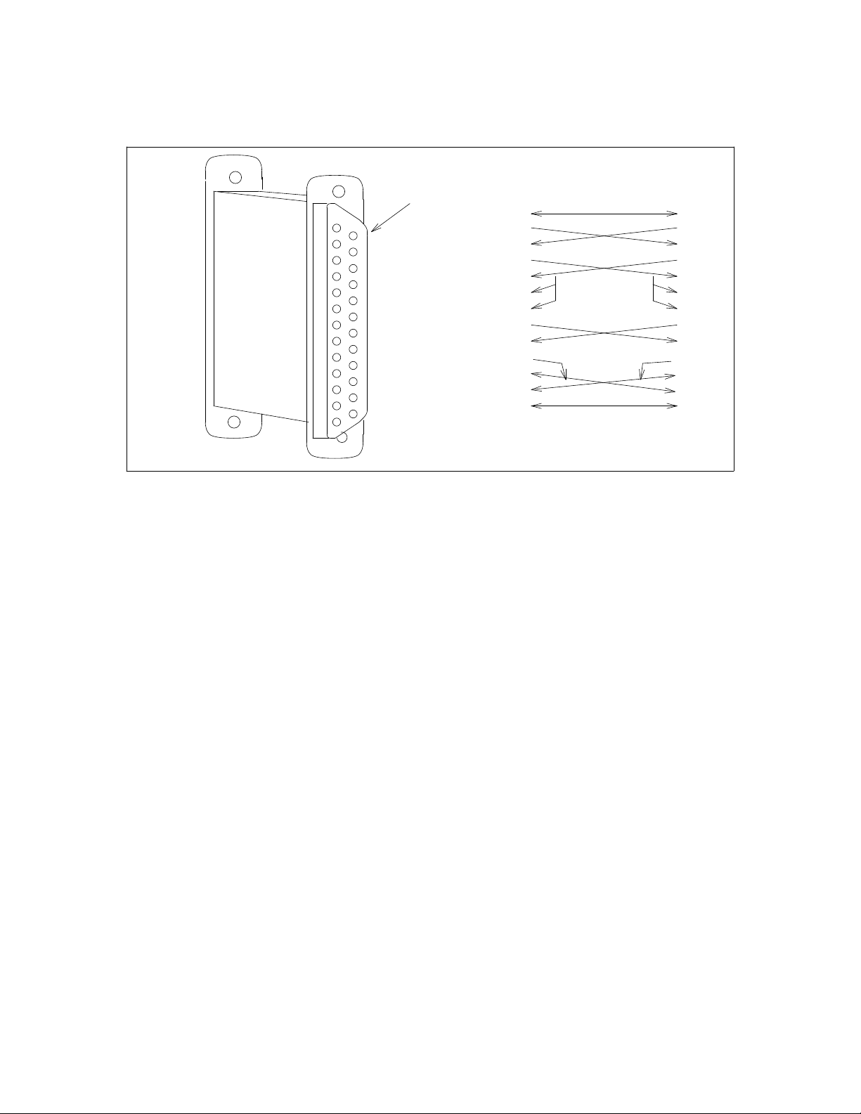
Figure 1-1. H600-330, Group 1 AUDIX Special Null-Modem Cable
H600-331, Group 2 Cable
Standard RS-232
Female Connector
(Both Sides)
Pins
1
14
2
15
3
16
4
17
5
18
6
19
7
20
8
21
9
22
10
23
11
24
12
25
13
Internal Connections of the
Special AUDIX Null-Modem
1 1
2
3
20
6
22
8
4
5
24
15
17
7
2
3
20
6
22
8
4
5
24
15
17
7
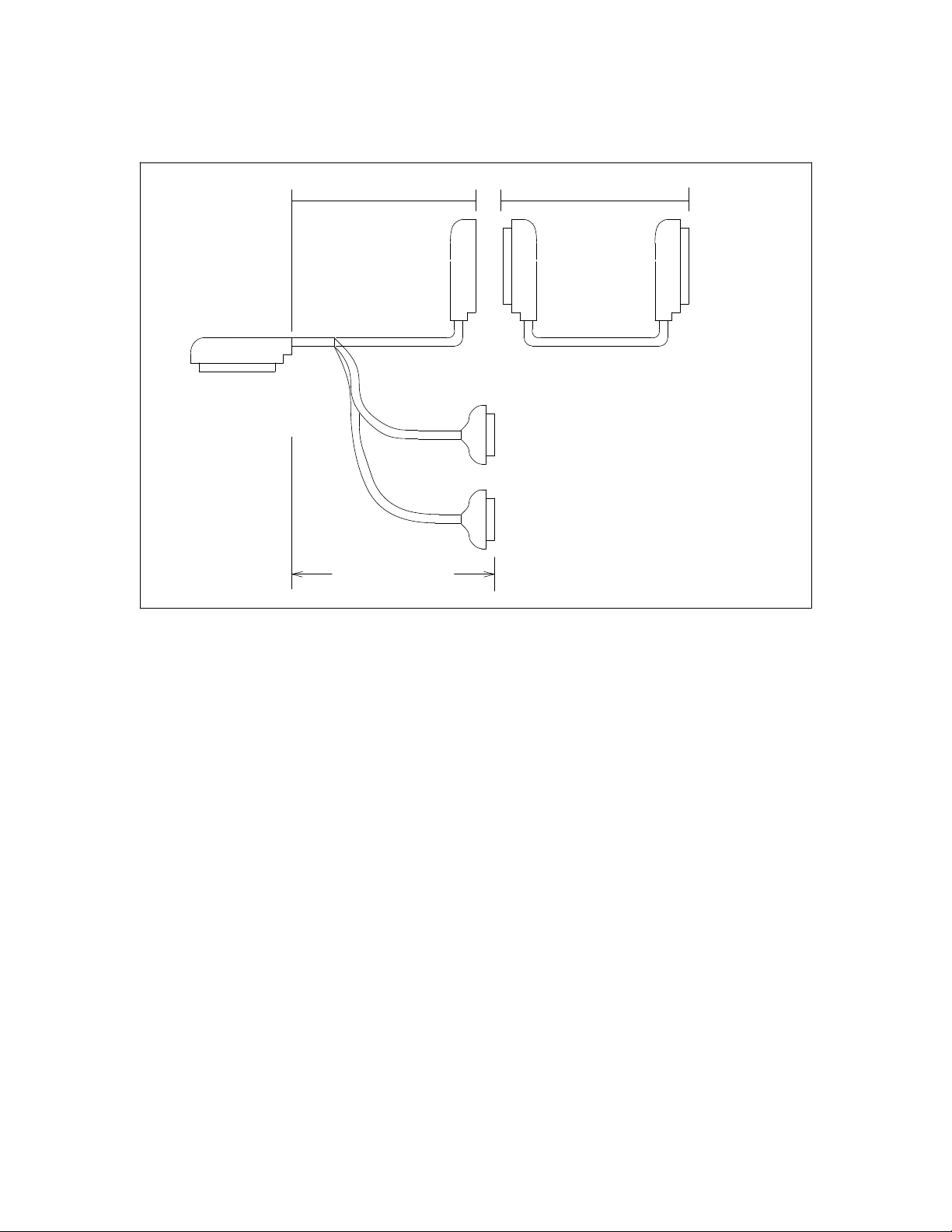
All new AUDIX networking systems are shipped with one H600-331, Group 2 breakout cable. One end of
the Group 2 cable is a 50-pin male Amphenol connector that connects to the ACCE on the AUDIX system.
The other end of the cable has a 50-pin female Amphenol connector and two 25-pin RS-232 male
connectors. See Table 1-1 for the pin assignments.
The female Amphenol connector provides access to the four DCP channels (AUDIX networking channels
1, 2, 3, and 4). The RS-232 connector A provides access to one RS-232 channel (AUDIX networking
channel 5), and RS-232 connector B provides access to the other RS-232 channel (AUDIX networking
channel 6).
Table 1-1. Pin Assignments for the H600-331, Group 2 Cable
_ ______________________________________________________________________________________
Connector Pin Number
_ ______________________________________________________________________________________
_ ______________________________________________________________________________________
50-Pin Amphenol shield 7 34 9 14 33 35 13 38 39 36 12 8 32 11
RS-232 A 1 2 3 4 5 6 7 8 12 13 15 17 20 22 24
_ ______________________________________________________________________________________
_ ______________________________________________________________________________________
50-Pin Amphenol shield 21 46 23 48 24 16 47 17 42 19 44 18 49 43
RS-232 B 1 2 3 4 5 6 7 8 12 13 15 17 20 22 24
_ ______________________________________________________________________________________
Page 29
_ ______________________________________________________________________________________
_ ______________________________________________________________________________________
_ ______________________________________________________________________________________
2.4 FT. (0.73M) UP TO 200 FT (60.96M)
AMPHENOL 50-PIN
CONNECTS TO AUDIX
ACCE PORT
AMPHENOL 50-PIN
MALE CONNECTOR
FEMALE CONNECTOR
ED-1E434-11 GROUP 300
50 PIN MALE-MALE
OR
ED-1E434-11 GROUP 500
50 PIN MALE-FEMALE
PATCH TO
CROSS-CONNECT
FIELD
A
Introduction 1-9
CONNECT TO DEDICATED
OR SWITCHED RS-232
ENDPOINTS
B
RS-232 25-PIN
5.0 FT (1.524 M)
MALE CONNECTORS
Figure 1-2. H600-331, Group 2 AUDIX Networking Breakout Cable
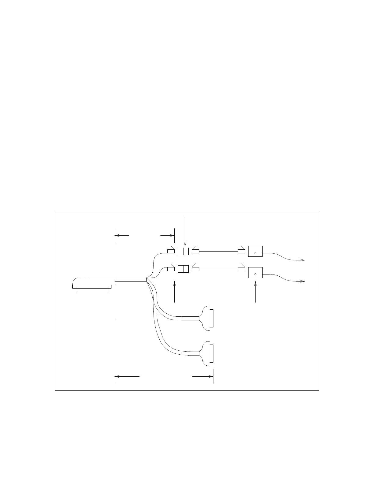
H600-331, Group 1 Cable
The H600-331, Group 1 breakout cable is no longer shipped; only an AUDIX system that is already
installed will have the Group 1 networking cable. One end of this cable is a 50-pin male Amphenol
connector that connects to the ACC or ACCE on the AUDIX system. The other end of the cable has two
8-pin DCP connectors and two 25-pin RS-232 male connectors. See Table 1-2 for pin assignments.
The H600-331, Group 1 DCP connector 0 provides access to two DCP channels (AUDIX networking
channels 1 and 2). DCP connector 1 also provides access to two DCP channels (AUDIX networking
channels 3 and 4). The two 451A adapters are shipped on the ends of connectors 0 and 1. The D8W-87
extension cords and 103A adapters must be ordered separately.
The H600-331, Group 1 RS-232 connector A also provides access to one RS-232 channel (AUDIX
networking channel 5), and RS-232 connector B provides access to another RS-232 channel (AUDIX
networking channel 6).
Page 30
1-10 Introduction
________________________________________________________________________________________________
________________________________________________________________________________________________
________________________________________________________________________________________________
Table 1-2. Pin Assignments for the H600-331, Group 1 Cable
_ ______________________________________________________________________________________
Connector Pin Number
_ ______________________________________________________________________________________
_ ______________________________________________________________________________________
50 Pin Amphenol shield 7 34 9 14 33 35 13 38 39 36 12 8 32 11
RS-232 A 1 2 3 4 5 6 7 8 12 13 15 17 20 22 24
_ ______________________________________________________________________________________
_ ______________________________________________________________________________________
50 Pin Amphenol shield 21 46 23 48 24 16 47 17 42 19 44 18 49 43
RS-232 B 1 2 3 4 5 6 7 8 12 13 15 17 20 22 24
_ ______________________________________________________________________________________
_ ______________________________________________________________________________________
50 Pin Amphenol 27 2 28 3
DCP 0 1 2 3 6
_ ______________________________________________________________________________________
_ ______________________________________________________________________________________
50 Pin Amphenol 30 5 31 6
DCP 1 1 2 3 6
_ ______________________________________________________________________________________
3.0 FT
(0.914 M)
451A ADAPTERS, 8-PIN
F/F (COMES WITH THE
CABLE)
PATCH TO DCP
INTERFACE AT
THE CROSS-
CONNECT FIELD
CONNECTS TO AUDIX
ACC(E) PORT
AMPHENOL 50-PIN
MALE CONNECTOR
Figure 1-3. H600-331, Group 1 AUDIX Networking Breakout Cable
0
1
5.0 FT (1.524 M)
D8W-87
EXTENSIONS
UP TO 25 FT
(7.625 M)
MODULAR 8-PIN
MALE CONNECTORS
A
B
103A ADAPTERS,
8-PIN to 6-WIRE
CONNECT TO DEDICATED
OR SWITCHED RS-232
ENDPOINTS
RS-232 25-PIN
MALE CONNECTORS
Page 31

_ ______________________________________________________________________________________
_ ______________________________________________________________________________________
_ ______________________________________________________________________________________
Introduction 1-11
AUDIX System Administration
In order for the AUDIX system to recognize messages addressed to subscribers at other AUDIX systems, it
must be administered with remote machine and remote subscriber profiles. Dial strings, transmission
intervals, connection types, and so forth must also be assigned. Each AUDIX system in the network
requires this administration of each of the other systems. See Chapter 13, AUDIX System Administration.
NETWORKING ENHANCEMENTS
The AUDIX Networking feature was enhanced for R1V5, R1V6, and R1V7.
R1V5 Release
Major changes brought about by AUDIX R1V5 software and the TN539 ACCE circuit pack:
• RS-232 connectivity between AUDIX systems. Previously, only DCP was supported. To use RS-232,
the AUDIX system must be running R1V5 or later software and the TN539 ACCE circuit pack is
required.
• DCP Mode 1 access to a switched 56 network (that is, 56 Kbps digital transmission) is supported. The
AUDIX system must be running R1V5 or later software (56 Kbps loop-around testing is not offered
until R1V7). Each AUDIX system requiring access to the switched 56 network must be equipped with
the TN539 or TN539B ACCE circuit pack.
• Multi-Stage Dialing is supported. This allows the use of modem pooling to provide a remote AUDIX
network for a non-DCP switch. The AUDIX system must be equipped with a TN539 or TN366B
circuit pack, the system must be running R1V5 or later software, and a switch supporting DCP must be
on site.
• The TN539 ACCE circuit pack can be used with R1V3 and R1V4 AUDIX software, but the RS-232
ports are not available unless R1V5 or later software is used.
• The TN366 or TN366B circuit pack can be used with R1V5 or later software, but the RS-232 ports and
access to 56 or 64 Kbps facilities require the TN539 or TN539B ACCE.
• A network can consist of a mixture of R1V3, R1V4, R1V5, R1V6, and R1V7 AUDIX systems.
However, the Sending Restrictions feature cannot be used anywhere in a network with R1V3 or R1V4
AUDIX systems.
• Network address ranges — up to 16 AUDIX systems can have the same range specified. The old limit
(R1V3 and R1V4) is eight.
Page 32

1-12 Introduction
________________________________________________________________________________________________
________________________________________________________________________________________________
________________________________________________________________________________________________
R1V6 Release
Major changes brought about by AUDIX R1V6 software and the vintage 7 TN539:
• With the R1V3, R1V4, and R1V5 software releases, only four channels could be simultaneously active.
AUDIX systems with R1V6 software and a vintage 7 TN539 or TN539B ACCE can use all six
networking ports simultaneously (however, System 75, Generic 1, Generic 3, and MERLIN II can still
only access two of the four DCP channels).
If a customer is upgrading to R1V5 or R1V6 from an existing network, and the RS-232
NOTE
channels and/or six simultaneous channels are not required, the existing TN366 or
TN366B can be retained. The new TN539 can replace the old circuit pack while the
cabling to the switch is left intact.
R1V7 Release
Major changes brought about by AUDIX R1V7 software and the TN539B board:
• The new TN539B ACCE board can provide faster throughput than previous networking boards for
networks with heavy traffic.
• The R1V7 software and the TN539B ACCE board permit 56 or 64 Kbps loopback testing; the serving
office can send data to an AUDIX port and, if the connection is up, the AUDIX system will echo the
data back to the serving office. See Chapter 14, AUDIX Network Testing for details.
• On R1V7 systems, the network turnaround feature can be administered. This option is activated using
the system : translation : machine : audix/amis/call delivery form; it can
be administered on a system-wide or per-machine basis.
— If network connection turnaround is implemented, the local machine will call a remote machine and
do the following: notify the remote system of its updated subscriber information, request updated
subscriber information from the remote system, and send voice mail and updated message status
information to the remote system. Then network connection will then be turned around and the
remaining events will occur: the remote system will request updated subscriber information from
the local system, notify the local system of its updated subscriber information, and send voice mail
and updated message status information to the local system.
— If the network turnaround feature is not implemented, the local machine will call a remote machine
and do the following: notify the remote system of its updated subscriber information, request
updated subscriber information from the remote system, and send voice mail and updated message
status information to the remote system. The call will then be disconnected.
The network turnaround feature reduces system overhead time and long-distance charges by allowing
all of these events to occur with a single call rather than two calls. If cost control from a central point is
not critical, greater efficiency can be gained by implementing the network connection turnaround
feature. The connection can only be turned around once during a single call.
Page 33

_ ______________________________________________________________________________________
2. Dedicated EIA RS-232 Networks
_ ______________________________________________________________________________________
_ ______________________________________________________________________________________
AUDIX networking can be implemented using a dedicated Electronic Industries Association (EIA) RS-232
interface. This chapter presents dedicated RS-232 configurations supported by AT&T. These examples
show AUDIX using RS-232 at both ends. For networks with RS-232 and DCP mixed, see Chapter 7,
Mixtures of RS-232 and DCP Networks.
If your customer develops their own method, contact the Business Communications Systems Design Center
(BCSDC) to make sure the method is feasible. Each of the configurations presented here is accompanied
by the equipment required for the AUDIX systems.
System 75, DEFINITY Generic 1, Generic 3, and MERLIN II can access only two of the four
NOTE
DCP channels. This is a limitation regardless of the AUDIX software used and the
networking circuit pack provided. When mixing the two DCP channels with the two RS-232
channels, a maximum of four channels can be provided for these switches. An AUDIX
system installed with a System 85 or a DEFINITY Generic 2 can provide access to six
channels in this manner.
AUDIX R1V3, R1V4, and R1V5 software limit the number of simultaneously active
channels to four. To use all six channels simultaneously, an AUDIX system must have R1V6
or later software and a TN539 vintage 7 or TN539B ACCE.
CONSIDERATIONS
If a customer is considering using dedicated RS-232 connections in their AUDIX network, keep the
following in mind:
• Only local networking configurations are supported.
• A maximum of three AUDIX systems can be networked via this method.
• AUDIX software must be R1V5 or later.
• The customer needs a TN539 or TN539B networking board.
• This type of network can operate at speeds up to 64 Kbps (depending on distance).
GENERAL INFORMATION
Figure 2-1, Dedicated RS-232 Network of Two AUDIX Systems, shows two AUDIX systems networked
using dedicated RS-232 connections. The transmission schedules (that is, the times set up for one system
to connect to another for the purpose of transmitting messages) can be set so the systems will not attempt to
use the channel at the same time. If they do attempt simultaneous transmissions, the system denied access
2-1
Page 34

2-2 Dedicated EIA RS-232 Networks
________________________________________________________________________________________________
________________________________________________________________________________________________
________________________________________________________________________________________________
to the channel will retry automatically.
Normally both RS-232 channels are required for networking. If only one channel is used, the other channel
can be used for the AUDIX Call Detail Recording (CDR) feature. However, this configuration is only
appropriate for networks with low traffic volume. If a customer chooses to use a channel for CDR, AT&T
recommends running CDR only during non-peak hours, thereby leaving two ports available for networking
during peak hours. See Figure 2-2, Dedicated RS-232 Network of Two AUDIX Systems and a PC (Low
Traffic Only). A switched RS-232 configuration is always preferable for networks that do not have very
low traffic.
If another system must be added to Figure 2-1, this can be done as shown in Figure 2-3, Dedicated RS-232
Network of Three AUDIX Systems (Low Traffic Only). If a PC is required in this case, at least one channel
from each system must be converted to a switched connection. See Figure 2-4, Dedicated RS-232 Network
of Three AUDIX Systems and a PC. Instead of switching cables as with configurations such as Figure 2-2,
the PC has dial-up access to any AUDIX system in the network. There is more information on switched
connections in the next section.
Text Services and/or Call Detail Recording can be added using the DCP channels. See
NOTE
Chapter 4, DCP Mode 1 Networks — 56 Kbps, and Chapter 7, Mixtures of RS-232 and DCP
Networks.
When there are more systems and/or PCs than channels, contention for the channels may occur. This
situation can usually be avoided, however, by scheduling the transfer of data at different times of the day.
See Chapter 13, AUDIX System Administration for details on how to set up transmission schedules. Even
when contention does occur, an AUDIX system will try to establish a connection two more times. If still
unable to make the connection, the AUDIX system will try again at the next scheduled interval or when the
transmission queue becomes full.
RS-232
AUDIX
SWITCH
H600-331
GROUP 2
H600-331
GROUP 2
H600-330
GROUP 1
(TWO SHOWN)
AUDIX
RS-232
Figure 2-1. Dedicated RS-232 Network of Two AUDIX Systems
Page 35

_ ______________________________________________________________________________________
Dedicated EIA RS-232 Networks 2-3
_ ______________________________________________________________________________________
_ ______________________________________________________________________________________
RS-232
AUDIX
SWITCH
H600-331
GROUP 2
H600-331
GROUP 2
H600-330
GROUP 1
(TWO SHOWN)
AUDIX
RS-232
M25A RS-232
EXTENSION
CABLES
NOTE:
Only one cable can be
connected at a time
RS-232
CALL DETAIL
RECORDING
Figure 2-2. Dedicated RS-232 Network of Two AUDIX Systems and a PC (Low Traffic Only)
RS-232
AUDIX
H600-331
SWITCH
GROUP 2
H600-331
GROUP 2
H600-331
GROUP 2
RS-232
AUDIX
RS-232
AUDIX
H600-330
GROUP 1
(TWO SHOWN)
H600-330
GROUP 1
RS-232
Figure 2-3. Dedicated RS-232 Network of Three AUDIX Systems (Low Traffic Only)
Page 36

2-4 Dedicated EIA RS-232 Networks
________________________________________________________________________________________________
________________________________________________________________________________________________
________________________________________________________________________________________________
H600-331
GROUP 2
MODEM
RS-232
H600-331
GROUP 2
RS-232
AUDIX
H600-330
GROUP 1
AUDIX
AUDIX
CALL DETAIL
RECORDING
SWITCH
MODEM
MODEM
MODEM
MODEM
RS-232
H600-331
GROUP 2
RS-232
RS-232
RS-232
Figure 2-4. Dedicated RS-232 Network of Three AUDIX Systems and a PC
AUDIX REQUIREMENTS FOR DEDICATED RS-232
Each AUDIX system must be running R1V5 or later software. Each AUDIX must be equipped with a
TN539 or TN539B ACCE circuit pack. The AUDIX Networking Breakout cable (H600-331, Group 2) and
the special AUDIX null-modems (H600-330, Group 1) are provided with each TN539 or TN539B ordered.
Standard null-modems cannot be substituted for the AUDIX null-modems.
NOTE
Page 37

_ ______________________________________________________________________________________
_ ______________________________________________________________________________________
_ ______________________________________________________________________________________
Dedicated EIA RS-232 Networks 2-5
SWITCH (OR CUSTOMER) REQUIREMENTS FOR DEDICATED RS-232
If the distance between systems is greater than 10 feet (3.05 meters), an M25A RS-232 extender cable
(male-female) is required in addition to the H600-331, Group 2 cable and H600-330, Group 1 null-modems
at each AUDIX system. Only one null-modem is required in each link. The extender cable is inserted on
one side of the null-modem. See Figure 2-5, Dedicated RS-232 Extended Connections. This cable comes
in lengths up to 50 feet (15.24 meters).
If the distance between AUDIX systems is greater than 50 feet, you can do one of two things:
• In addition to the H600-331, Group 2 cable at each AUDIX system, a pair of data sets must be inserted
in place of the null-modem (see Figure 2-5). The data sets must be Z3A Asynchronous Data Units
(ADU). The following equipment is required (see Figure 8-3). Two Z3A Asynchronous Data Units
(ADU), two D8W-87 modular cords, two 103A adapters, one D8AM-87 crossover cord, external power
on one end (400B adapter, D6AP-87 modular cord, 248B adapter, and a Model 2012D transformer),
and building wire (4-wire).
Check the document(s) shipped with the data sets for the maximum distances allowed.
• The dedicated connection can be recabled as a switched connection. See Chapter 3, Switched EIA
RS-232 Networks.
DATA RATES FOR DEDICATED RS-232
Data rate limitations are imposed on the RS-232 interface when certain distances are exceeded:
• At 20 feet (6.1 meters) or less, the data rate can be as high as 64 Kbps.
• At 20 to 50 feet (6.1 to 15.25 meters), the maximum data rate is 19.2 Kbps unless limited-distance
modems are used. Check with the documentation shipped with the limited-distance modems.
• At more than 50 feet (15.25 meters), limited-distance modems must be used. Check with the
documentation shipped with the limited-distance modems.
Configurations with limited-distance modems are supported only as custom work.
NOTE
Page 38

2-6 Dedicated EIA RS-232 Networks
________________________________________________________________________________________________
________________________________________________________________________________________________
________________________________________________________________________________________________
DATA
SWITCH
AUDIX
SET
SWITCH
SWITCH
AUDIX
H600-331
GROUP 2
AUDIX
H600-330
GROUP 1
H600-331
GROUP 2
M25B RS-232
EXTENSION
CABLE
DATA
SET
BUILDING
WIRE
DATA
SET
H600-331
GROUP 2
Figure 2-5. Dedicated RS-232 Extended Connections
Page 39

_ ______________________________________________________________________________________
3. Switched EIA RS-232 Networks
_ ______________________________________________________________________________________
_ ______________________________________________________________________________________
AUDIX networks can be implemented using a switched Electronic Industries Association (EIA) RS-232
connection. Networks can also be implemented by converting the RS-232 channels into switched Digital
Communications Protocol (DCP) connections. This chapter presents supported configurations for both
methods. The examples show an AUDIX system using RS-232 at both ends. See Chapter 7, Mixtures of
RS-232 and DCP Networks, for RS-232/DCP combinations.
If your customer develops their own method, contact the Business Communications Systems Design Center
(BCSDC) to make sure the method is feasible. Each of the examples presented here is accompanied by the
equipment required for the AUDIX systems and for the switches the AUDIX systems serve.
CONSIDERATIONS
If a customer is considering using switched RS-232 connections in their AUDIX network, keep the
following in mind:
• Local or remote networking configurations are supported.
• Two or more AUDIX systems can be networked via this method.
• AUDIX software must be R1V5 or later.
• The customer needs a TN539 or TN539B networking board.
• In this type of network speeds can be up to 19.2 Kbps; speeds are limited by the modems or data
modules the customer chooses to use.
• The customer will need data modules or Hayes-compatible modems for each AUDIX channel to be
switched.
System 75, DEFINITY Generic 1 and Generic 3, and MERLIN II can only access two of the
NOTE
four AUDIX DCP channels. This is a limitation regardless of the AUDIX software used and
the networking circuit pack provided. Thus, conversion of the RS-232 channels to DCP
becomes of particular importance in these cases. When mixing the two DCP channels with
the two RS-232 channels, a maximum of four channels can be provided for these switches.
AUDIX installed with a System 85 or a DEFINITY Generic 2 can provide access to six
channels in this manner.
For a System 85 or Generic 2, AUDIX R1V3, R1V4, and R1V5 software limit the number of
simultaneously active channels to four. To use all six channels simultaneously with a System
85 or Generic 2, an AUDIX system must have R1V6 or later software and a TN539 vintage 7
or TN539B ACCE.
3-1
Page 40

3-2 Switched EIA RS-232 Networks
________________________________________________________________________________________________
________________________________________________________________________________________________
________________________________________________________________________________________________
SWITCHED RS-232 USING MODEMS
When a dedicated RS-232 network requires more than three AUDIX systems, or any time two systems are
separated by a distance greater than two data sets can support, a switched RS-232 network must be formed.
Modems convert the RS-232 signal into an analog signal for transmission through the switch to a colocated
AUDIX system, or out of the switch across the public/private facilities to another switch.
Figure 3-1, Dedicated and Switched RS-232 Network for a Single Switch, shows four AUDIX systems
serving the same switch. Notice that in this example there is a mixture of dedicated and switched
connections. Incorporating two dedicated connections into this setup saves the customer the price of four
modems. Whether this is a viable setup depends on the network usage between all systems.
If the network requires switched access to all RS-232 channels, the network would look like Figure 3-2,
Switched RS-232 Network for a Single Switch.
Figure 3-3, Switched RS-232 Network for Separate Locations, shows three AUDIX systems serving
switches at different locations. This setup also presents a mixture of dedicated and switched connections.
The assumption is that the two systems serving the same switch will have much more use for a network
connection, so a dedicated connection is provided. For the occasional connection to/from the other site, a
switched connection is used.
If Call Detail Recording is required, a PC can be included in a switched RS-232 network using a spare
dedicated RS-232 connection or through a switched RS-232 connection. Figure 3-4, Switched RS-232
Network for Separate Locations and a PC, shows a switched connection. The PC has dial-up access to any
AUDIX system in the network.
Page 41

_ ______________________________________________________________________________________
Switched EIA RS-232 Networks 3-3
_ ______________________________________________________________________________________
_ ______________________________________________________________________________________
H600-331
GROUP 2
MODEM
RS-232
H600-331
GROUP 2
RS-232
AUDIX
H600-330
GROUP 1
SWITCH
MODEM
MODEM
MODEM
RS-232
H600-331
GROUP 2
RS-232
H600-331
GROUP 2
RS-232
AUDIX
AUDIX
RS-232
AUDIX
H600-330
GROUP 1
Figure 3-1. Dedicated and Switched RS-232 Network for a Single Switch
Page 42

3-4 Switched EIA RS-232 Networks
________________________________________________________________________________________________
________________________________________________________________________________________________
________________________________________________________________________________________________
AUDIX System Requirements For Switched RS-232 Using Modems
Each AUDIX system must be running R1V5 or later software. Each AUDIX system must be equipped
with a TN539 or TN539B ACCE circuit pack. The AUDIX Networking Breakout cable (H600-331, Group
2) is required at each AUDIX system.
H600-331
GROUP 2
MODEM
RS-232
T/R
AUDIX
ALL CONNECTIONS
TO ANALOG PORTS
SWITCH
T/R
T/R
T/R
MODEM
MODEM
MODEM
H600-331
GROUP 2
AUDIX
RS-232
H600-331
GROUP 2
AUDIX
RS-232
H600-331
GROUP 2
AUDIX
RS-232
Figure 3-2. Switched RS-232 Network for a Single Switch
Switch (or Customer) Requirements For Switched RS-232 Using Modems
Each switched RS-232 channel requires one of the following Hayes-compatible modems:
• AT&T 2296A
• AT&T Paradyne 3820
• AT&T Paradyne DM424
• MICROCOM QX 3296/C (not orderable through AT&T)
Page 43

_ ______________________________________________________________________________________
_ ______________________________________________________________________________________
_ ______________________________________________________________________________________
Equivalent modems such as the AT&T Paradyne DL424 instead of the DM424 modem could
Switched EIA RS-232 Networks 3-5
NOTE
be used.
The modem requires a connection through one of the switch’s analog ports or can connect directly to a CO
line. Switch analog port circuit packs are:
• System 75, Generic 1, and Generic 3: TN742 or TN746B analog line circuit
• System 85 and Generic 2 traditional module: SN222, SN228, or SN228B analog line circuit
• System 85 and Generic 2 universal module: TN742 or TN746B analog line circuit
H600-331
GROUP 2
AUDIX
AUDIX
ALL CONNECTIONS
TO ANALOG PORTS
T/R
SWITCH
T/R
T/R
MODEM
H600-330
GROUP 1
MODEM
RS-232
H600-331
GROUP 2
RS-232
PUBLIC/PRIVATE
INTERLOCATION
FACILITIES
T/R
SWITCHED LINES
TO THE CENTRAL OFFICE
SWITCH
T/R
MODEM
NOT
USED
H600-331
GROUP 2
AUDIX
RS-232
Figure 3-3. Switched RS-232 Network for Separate Locations
If the modems must be located greater than 5.0 feet (1.524 meters) from the AUDIX system, an M25A RS232 extender cable is required for each. The modem must be within 50 feet (15.24 meters) of the AUDIX
system. The tip/ring circuit should be engineered by a switch representative.
Page 44

3-6 Switched EIA RS-232 Networks
________________________________________________________________________________________________
________________________________________________________________________________________________
________________________________________________________________________________________________
Data Rates for Switched RS-232 Using Modems
When connected through the switch, data rates are limited to speeds up to and including 19.2 Kbps. The
speeds may be reduced by the limit of the modems and the public/private facilities involved.
H600-331
GROUP 2
AUDIX
AUDIX
ALL CONNECTIONS
TO ANALOG PORTS
T/R
SWITCH
T/R
T/R
MODEM
MODEM
RS-232
H600-331
GROUP 2
MODEM
MODEM
RS-232
T/R
PUBLIC/PRIVATE
INTERLOCATION
FACILITIES
SWITCHED LINES
TO THE CENTRAL OFFICE
MODEM
SWITCH
T/R
T/R
MODEM
NOT
USED
RS-232
H600-331
GROUP 2
AUDIX
RS-232
Figure 3-4. Switched RS-232 Network for Separate Locations and a PC
Page 45

_ ______________________________________________________________________________________
_ ______________________________________________________________________________________
_ ______________________________________________________________________________________
SWITCHED RS-232 USING DATA MODULES FOR DCP
By using a data module instead of a modem, the RS-232 channel becomes a DCP channel, at least as far as
the switch and the switch network is concerned. RS-232 channels can be converted to DCP mode 1, DCP
mode 2, or DCP mode 3. See Figure 3-5, Converting RS-232 Channels to DCP.
• To convert to DCP mode 1 (56 Kbps) or DCP mode 3 (64 Kbps), use a Modular Processor Data
Module, Model M1* (MPDM/M1*). In either of these cases, the channels can only be used for
incoming calls; they cannot be used for outgoing calls. All outgoing calls must use the DCP ports.
• To convert to DCP mode 2, use a 7400A or 7400B Data Service Unit (DSU). In this case, the channels
can be used for incoming or outgoing calls.
Converting RS-232 channels to DCP is particularly useful for System 75, Generic 1, Generic 3, and
MERLIN II where a DCP network is desired. Adding the two converted channels to the regular two DCP
channels creates a total of four DCP channels. (If the customer desires, these channels can be left as RS232 channels giving two RS-232 and two DCP channels, again for a total of four channels. See Chapter 7,
Mixtures of RS-232 and DCP Networks, for examples.)
Switched EIA RS-232 Networks 3-7
Public/Private
Interlocation
Facilities
NOTE: The 7400A and 7400B
data modules are
bi-directional;
the MPDM/M1* is for
incoming calls only.
(Two Channels)
Sys 75,
G1, or
G3
DCP
(Two Channels)
Sys 85
or G2
DCP
Data
Module
DCP
(Two Channels)
DCP
RS-232
(Four Channels)
Data
Module
Figure 3-5. Converting RS-232 Channels to DCP
AUDIX
H600-331
Group 2
AUDIX
RS-232
H600-331
Group 2
Page 46

3-8 Switched EIA RS-232 Networks
________________________________________________________________________________________________
________________________________________________________________________________________________
________________________________________________________________________________________________
AUDIX System Requirements for Switched RS-232 Using Data Modules For DCP
Each AUDIX system must be running R1V5 or later software and must be equipped with a TN539 or
TN539B ACCE circuit pack and the AUDIX Networking Breakout cable (H600-331 Group 1 or 2).
Switch (or Customer) Requirements for Switched RS-232 Using Data Modules for DCP
Each AUDIX RS-232 channel to be converted to DCP requires a data module. The data module must be
connected to a DCP port at the switch and should be located within 5 feet (1.524 meters) of the AUDIX
system, so an M25A RS-232 extender cable is not needed. The distance from the data module to the switch
should be no more than 5000 feet (1524 meters). The following is required:
• One of the following data modules:
— For DCP mode 1 (56 Kbps, synchronous) or DCP mode 3 (64 Kbps, synchronous) use an
MPDM/M1*. The MPDM/M1* operates in synchronous mode. An older MPDM can be upgraded
to support 56 Kbps with D-kit D-181509. Install the D-kit by following the instructions included
with the kit. These channels can only be used for incoming calls.
— For DCP mode 2, use a 7400A or 7400B DSU. The 7400A and 7400B operate in only
asynchronous mode. These channels can be used for incoming or outgoing calls.
• One D8W-87 modular cord (provided with the data module) is required for each module.
• Switch DCP interface:
— System 75, Generic 1, and Generic 3: TN754 Digital Line Circuit
— System 85 and Generic 2 traditional module: SN270B General Purpose Port
— System 85 and Generic 2 universal module: TN754
If the converted channels are to be used for DCP Mode 2 operation, two modem pool pairs are also
required. See Chapter 5, DCP Mode 2 Networks — Modem Pooling. Access to two additional channels on
the interlocation facilities might also be required.
Data Rates for Switched RS-232 Using Data Modules For DCP
Data rates are limited to the capabilities of the data modules. MPDM/M1* data modules operate at 56 or
64 Kbps (synchronous), but they do not support dialing out at these speeds, so the converted channels
would be limited to receiving calls only. In some cases this limitation would not create a problem. In cases
where it would, the 7400A data module, which supports incoming and outgoing calls, can be used.
However, with the 7400A, communication is performed at low speeds (up to and including 19.2 Kbps,
asynchronous).
Page 47

_ ______________________________________________________________________________________
4. DCP Mode 1 Networks — 56 Kbps
_ ______________________________________________________________________________________
_ ______________________________________________________________________________________
AUDIX networks can be implemented using AT&T’s Digital Communications Protocol (DCP) Mode 1.
This type of network is only used when the AUDIX systems to be networked are not colocated and,
therefore, they require some type of interlocation facility to pass data. (For local networking, see Chapter
6, DCP Mode 3 Networks — 64 Kbps.) This chapter presents supported 56 Kbps configurations; all other
56 Kbps configurations must be designed by Custom Development.
The examples show an AUDIX system using DCP at both ends. See Chapter 7, Mixtures of RS-232 and
DCP Networks, for RS-232/DCP combinations. Each of the examples presented in this chapter is
accompanied by the equipment required for the AUDIX systems and for the switches that the AUDIX
systems serve.
Customers who implemented 56 Kbps networking using TN539 ACCE boards may wish to
NOTE
CONSIDERATIONS
upgrade to AUDIX R1V7 software and a TN539B ACCE in order to take advantage of the
performance improvements and built-in loop-around testing capabilities.
If a customer is considering using DCP Mode 1 connections in their AUDIX network, keep the following in
mind:
• Only remote networking configurations are supported.
• Two or more AUDIX systems can be networked via this method.
• AUDIX software must be R1V5 or later. However, R1V7 software is recommended because of the
networking feature enhancements and 56 Kbps loopback testing capabilities included in that load when
a TN539B ACCE board is used.
• AUDIX systems running R1V5 or R1V6 software require an MPDM/M1* for loopback testing.
AUDIX R1V7 systems only require an MPDM/M1* if the two RS-232 ports are to be converted for 56
Kbps use.
• The customer needs a TN539 or TN539B ACCE networking board; the TN539B is recommended
because of the 56 Kbps loopback testing capabilities included in that load when AUDIX R1V7 software
is used.
• Transmission in this type of network is full-duplex, synchronous, at 56 Kbps.
• The customer will need access to 56 Kbps robbed-bit facilities to a static or dynamic serving office
(SO).
• The customer will also need a DCP interface on the switch to connect with the AUDIX and a DS1
interface on the switch to connect with the 56 Kbps network.
4-1
Page 48

4-2 DCP Mode 1 Networks — 56 Kbps
________________________________________________________________________________________________
________________________________________________________________________________________________
________________________________________________________________________________________________
MERLIN II, System 75, and DEFINITY Generic 1 and Generic 3 can only access two of the
NOTE
four DCP channels. This is a limitation regardless of the AUDIX software and networking
circuit pack used. See Chapter 3, Switched EIA RS-232 Networks, for information on
expanding this limitation to four channels by adding the AUDIX RS-232 channels.
GENERAL INFORMATION
To use DCP Mode 1 as the transmission protocol, the switch must be set up to access a switched network at
56 Kbps via robbed-bit facilities. These special access lines can be either Dataphone Digital Service (DDS)
or ACCUNET T1.5, SDN service providing access to either a static or dynamic Serving Office (SO), or
compatible services provided by other vendors. Currently the System 75, System 85, DEFINITY Generic
1, Generic 2, or Generic 3 can provide this type of access. However, System 85 (R2V3 or R2V4) does not
support dynamic access. Up to six channels on the 56 Kbps service facility may be required at any one
time for System 85 and Generic 2 and up to four channels for System 75, Generic 1, and Generic 3.
Figure 4-1, DCP Mode 1 Network Using Switched 56 Service, shows an arrangement where AUDIX
networking is accomplished via 56 Kbps services. Figure 4-2, PC Added to A DCP Network, shows a
network of R1V5 or later AUDIX systems with RS-232 access. When RS-232 is available, the customer
has a choice of connecting a PC for the CDR feature via dedicated or switched RS-232 (dedicated RS-232
is shown in Figure 4-2).
NOTE
If the customer does not subscribe to switched 56 service, check with the DCP Mode 2, DCP
Mode 3, and RS-232 network alternatives before setting up a switched 56 Kbps facility.
Page 49

_ ______________________________________________________________________________________
DCP Mode 1 Networks — 56 Kbps 4-3
_ ______________________________________________________________________________________
_ ______________________________________________________________________________________
CROSS-CONNECT
FIELD
POINT-OF
PRESENCE
SWITCH
SWITCHED 56
SERVICE
POINT-OF
PRESENCE
SWITCH
SWITCH
CROSS-CONNECT
FIELD
SWITCH
H600-331, GROUP 2
DCP
DCP
AUDIX
RS-232
(NOT EQUIPPED)
H600-331
GROUP 2
AUDIX
RS-232
(NOT EQUIPPED)
Figure 4-1. DCP Mode 1 Network Using Switched 56 Service
Page 50

4-4 DCP Mode 1 Networks — 56 Kbps
________________________________________________________________________________________________
________________________________________________________________________________________________
________________________________________________________________________________________________
Static Access
Static SDDN (non-ISDN) allows customers currently subscribing to SDN voice applications to transmit
data on the same access arrangement by designating a subgroup defined for data terminations. Customers
using this configuration must have a trunk subgroup (TSG) dedicated to SDDN 56 Kbps between the
customer premises and a central office. They must also have a System 75 R1V3 Issue 2.1 or later, a System
85 R2V3 or R2V4, or a DEFINITY Generic 1, Generic 2, or Generic 3 switch.
The central office must provide one of the following:
• SDN, T1.5, or DDS and Switched Digital Service (SDS), or compatible service offered by another
vendor
• A 4ESS supporting 56 Kbps service
A customer with T1.5 access to a central office tariffed for SDN and T1.5 that does not home to a 4ESS
with SDS cannot use this option.
Dynamic Access
Dynamic SDDN (non-ISDN) allows customers that currently subscribe to SDN voice applications to
transmit data on the same access arrangement by prefixing a 115 feature code in front of a telephone
number. This allows customers to alternately transmit voice and data on one access line; a separate trunk
group for 56 Kbps data is not required.
The T1.5 is dedicated to SDN and is therefore not exclusively 56 Kbps. The central office must route to a
4ESS that supports 56 Kbps via digital connectivity. This access may only be offered on circuits without
echo cancellation.
The dynamic arrangement is not possible from locations using DDS access. DDS lines must terminate in a
central office that has been tariffed for SDN, DDS, and SDS.
System 85 R2V3 and R2V4 do not support dynamic access. System 75 R1V3 and and DEFINITY Generic
1, Generic 2, and Generic 3 do support dynamic access. However, if a customer wants to use a Generic 2
for Switched 56 Kbps networking, contact the BCSDC for help.
Dynamic trunk group arrangements cannot be used by modem pooling. If a customer has
NOTE
both 56 Kbps and modem pooling, two trunk groups are required.
Page 51

_ ______________________________________________________________________________________
_ ______________________________________________________________________________________
_ ______________________________________________________________________________________
AUDIX SYSTEM REQUIREMENTS FOR DCP MODE 1
Each AUDIX system requiring access to a switched 56 network must be running R1V5 or later software.
Each AUDIX system must also be equipped with a TN539 or TN539B ACCE circuit pack, the AUDIX
Networking Breakout cable (H600-331, Group 1 or Group 2). Also, if the RS-232 ports are to be used for
DCP Mode 1 transmission, an MPDM/M1* with an RS-232 interface card is required. If loopback testing
is to be conducted for an R1V5 or R1V6 AUDIX system, an MPDM/M1* with a V.35 interface card is
required. In addition, each AUDIX system must be within 5000 cable feet (1525 meters) of the switch’s
DCP interface.
CROSS-CONNECT
FIELD
DCP Mode 1 Networks — 56 Kbps 4-5
POINT-OF
PRESENCE
SWITCH
ACCUNET
SWITCHED 56
NETWORK
POINT-OF
PRESENCE
SWITCH
SWITCH
SWITCH
DCP
H600-330
GROUP 1
CROSS-CONNECT
FIELD
DCP
H600-331
GROUP 2
AUDIX
RS-232
RS-232
CDR
H600-331
GROUP 2
AUDIX
RS-232
ACCESS
Figure 4-2. PC Added to a DCP Network
Page 52

4-6 DCP Mode 1 Networks — 56 Kbps
________________________________________________________________________________________________
________________________________________________________________________________________________
________________________________________________________________________________________________
SWITCH (OR CUSTOMER) REQUIREMENTS FOR DCP MODE 1
To implement AUDIX networking over static or dynamic switched 56 Kbps facilities, the customer’s
switch must have a DCP interface to connect with the AUDIX system and a DS1 interface to connect with
the 56 Kbps switched network.
Whether a customer is using static or dynamic 56 Kbps, the point-of-presence switch needs to be translated
to match the switch, (including wink in/wink out). The RNXs are set up by the customer and added to the
network by Network Systems.
Contact the Business Communications Systems Design Center (BCSDC) to design ISDN.
NOTE
The following equipment is typical for 56 Kbps facility access:
• Digital Line Circuits for the AUDIX network
• DS1 Interface
• For R1V5 or R1V6, a Modular Processor Data Module, Model M1* (MPDM/M1*) ACCUNET data
module with V.35 interface card (for loopback testing)
See the DEFINITY Communications System & System 75/85 DS1/DMI/ISDN-PRI
NOTE
Reference (555-025-101) for a complete specification of requirements.
Static Access Switch Requirements
The requirements for networking AUDIX systems via static 56 Kbps facilities depend on the customer’s
premise switch:
• System 75
— The switch must be R1V3 2.1 or later.
— All tone detectors must be TN748C (V4 or later).
• DEFINITY Generic 1 and Generic 3
— Any release will support static 56 Kbps access.
— All tone detectors must be TN748C (V4 or later).
Page 53

_ ______________________________________________________________________________________
_ ______________________________________________________________________________________
_ ______________________________________________________________________________________
DCP Mode 1 Networks — 56 Kbps 4-7
• System 85
— The switch must be R2V3 or R2V4
— All tone detectors must be at least an SN255.
• DEFINITY Generic 2
— Any release will support static 56 Kbps access.
— For universal modules, the detector must be a TN748C (V4 or later). For traditional modules, the
detector is a SN255.
Dynamic Access Switch Requirements
The requirements for networking AUDIX systems via dynamic 56 Kbps facilities depend on the customer
premise switch:
• System 75
— The switch must be R1V3 2.1 or later.
— All tone detectors must be TN748C (V4 or later).
• DEFINITY Generic 1 and Generic 3
— Any release will support dynamic 56 Kbps access.
— All tone detectors must be TN748C (V4 or later).
• System 85
— Does not support dynamic access.
• DEFINITY Generic 2
— Any release will support dynamic 56 Kbps access.
— For universal modules, the detector must be a TN748C (V4 or later). For traditional modules, the
detector is a SN255.
For help in designing dynamic switched 56 Kbps networking with a Generic 2, contact the BCSDC.
The MERLIN II does not support this arrangement. If your customer has a non-DCP switch
NOTE
and wishes to use DCP Mode 1, a DEFINITY Generic 1, Generic 2, or Generic 3 can be used
instead of the MERLIN II.
DATA RATES FOR DCP MODE 1
All of the configurations shown in this chapter operate at 56 Kbps.
Page 54

4-8 DCP Mode 1 Networks — 56 Kbps
________________________________________________________________________________________________
________________________________________________________________________________________________
________________________________________________________________________________________________
Page 55

_ ______________________________________________________________________________________
5. DCP Mode 2 Networks — Modem Pooling
_ ______________________________________________________________________________________
_ ______________________________________________________________________________________
AUDIX networks can be implemented using AT&T’s Digital Communications Protocol (DCP) Mode 2.
This type of network is only used when the AUDIX systems to be networked are not colocated and,
therefore, require some type of interlocation facility to pass data. This arrangement makes use of the
switch’s modem pool or can be implemented using stand-alone modem pools. This chapter presents
supported configurations. The examples show the AUDIX system using DCP at both ends. See Chapter 7,
Mixtures of RS-232 and DCP Networks, for RS-232/DCP combinations.
If a customer develops their own method, contact the Business Communications Systems Design Center
(BCSDC) to make sure it is feasible. Each of the examples presented here is accompanied by the
equipment required for the AUDIX systems and for the switches that the AUDIX systems serve.
CONSIDERATIONS
If a customer is considering using DCP Mode 2 connections in their AUDIX network, keep the following in
mind:
• Only remote networking configurations are supported.
• Two or more AUDIX systems can be networked via this method.
• AUDIX software must be R1V3 or later.
• The customer needs a TN366, TN366B, TN539, or TN539B networking board.
• Transmission in this type of network is full-duplex or half-duplex, synchronous or asynchronous, at
speeds up to 9600 bps.
• The customer will need rack-mounted or standalone modem pool.
System 75 and DEFINITY Generic 1 and Generic 3 can be set up to access only two of the
NOTE
four DCP channels. This is a limitation regardless of the AUDIX software used and the
networking circuit pack provided. See Chapter 3, Switched EIA RS-232 Networks, for
information on expanding this limitation to four channels.
5-1
Page 56

5-2 DCP Mode 2 Networks — Modem Pooling
________________________________________________________________________________________________
________________________________________________________________________________________________
________________________________________________________________________________________________
GENERAL INFORMATION
DCP Mode 2 networking uses the DCP interface between the AUDIX system and the switch. Analog or
voice-grade data facilities are used between customer locations. When the switch is a System 85 or
DEFINITY Generic 2, the AUDIX system can use up to six ports at any given time. When the switch is a
System 75, Generic 1, or Generic 3, up to four ports may be used at any given time.
Figure 5-1, Typical Rack-Mounted Modem Pool Using D-Lead Control, shows a modem pool where a D-
Lead is used between the modems and data modules. This arrangement is usually shared by two or more
switch applications. The customer can use this arrangement for AUDIX systems so long as the equipment
and their option settings are compatible. (Compatible equipment is provided later in this chapter.
Compatible option settings are provided in Chapter 11, DCP Mode 2 Installation and Administration.) The
customer could also use what is called stand-alone modem pooling. See Figure 5-2, Typical Stand-Alone
Modem Pool (No D-Lead Control).
2
2
2
2
2
9
9
6
6
A
A
2
2
2
2
2
9
9
9
6
6
6
A
A
A
2
2
2
2
2
2
9
9
9
6
6
6
A
A
A
105A MOUNTING
WITH 8 MODEMS
7
4
4
4
4
0
0
0
0
0
0
0
0
A
A
A
A
2
2
2
2
2
9
9
6
6
A
A
2
2
2
2
2
9
9
9
6
6
6
A
A
A
4
4
4
4
0
0
0
0
0
0
0
0
A
A
A
A
2
2
2
2
2
2
9
9
9
6
6
6
A
A
A
77A MOUNTING
WITH 8 DATA SETS
105A MOUNTING
7
7
7
7
7
7
7
WITH 8 MODEMS
7
4
4
4
4
0
0
0
0
0
0
0
0
A
A
A
A
7
4
4
4
4
0
0
0
0
0
0
0
0
A
A
A
A
77A MOUNTING
WITH 8 DATA SETS
NOTE:
Use 46A2 mounting
7
7
7
7
7
7
if MTDMs are used
instead of 7400As.
Figure 5-1. Typical Rack-Mounted Modem Pool Using D-Lead Control
Page 57

_ ______________________________________________________________________________________
DCP Mode 2 Networks — Modem Pooling 5-3
_ ______________________________________________________________________________________
_ ______________________________________________________________________________________
DCP
T/R
DCP
T/R
104A 104A
TO THE CROSSCONNECT FIELD
DCP
7400A
7400A
RS-232
T/R
DM424
OR
2296A
MODEMS
Figure 5-2. Typical Stand-Alone Modem Pool (No D-Lead Control)
In Figure 5-2, the modems and data modules are typically the models that are contained in their own
housings and placed on shelves or on top of other cabinets. However, they could be the rack-mounted
versions where they are cabled as stand-alone modem pools (no D-Lead). Stand-alone modem pools are
usually dedicated for a particular application.
Figure 5-3, DCP Mode 2 Network (Modem Pooling), shows a DCP Mode 2 network where the switches are
either System 75, System 85, Generic 1, Generic 2, or Generic 3.
Page 58

5-4 DCP Mode 2 Networks — Modem Pooling
________________________________________________________________________________________________
________________________________________________________________________________________________
________________________________________________________________________________________________
CROSS-CONNECT
FIELD
ANALOG OR
VOICE-GRADE
DATA
PUBLIC/PRIVATE
INTERLOCATION
FACILITIES
ANALOG OR
VOICE-GRADE
DATA
MODEM
POOL
MODEM
POOL
SWITCH
SWITCH
H600-331, GROUP 2
DCP
CROSS-CONNECT
FIELD
DCP
AUDIX
RS-232
ACCESS
H600-331
GROUP 2
AUDIX
Figure 5-3. DCP Mode 2 Network (Modem Pooling)
RS-232
ACCESS
Page 59

_ ______________________________________________________________________________________
_ ______________________________________________________________________________________
_ ______________________________________________________________________________________
DCP Mode 2 Networks — Modem Pooling 5-5
AUDIX SYSTEM REQUIREMENTS FOR DCP MODE 2
Each AUDIX system must be running R1V3 or later software and must be equipped with one of the
following:
• TN366 AUDIX Communications Controller (ACC) circuit pack
• TN366B ACC circuit pack
• TN539 ACC Enhanced (ACCE) circuit pack
• TN539B ACCE circuit pack
The AUDIX Networking Breakout cable (H600-331, Group 1 or Group 2) provides access to the DCP
channels at the AUDIX system. Also, each AUDIX system must be within 5000 cable feet (1525 meters)
of the switch’s DCP interface.
SWITCH (OR CUSTOMER) REQUIREMENTS FOR DCP MODE 2
The switch must have a DCP interface and some type of modem pool to provide access to the analog or
voice-grade-data interlocation facilities. For System 75, System 85, DEFINITY Generic 1, Generic 2, or
Generic 3, the modem pool may be:
• Rack-mounted with a D-Lead
• Rack-mounted or shelf-mounted as a stand-alone modem pool (no D-Lead)
It is strongly recommended that all modems in a modem pool be of the same make and
NOTE
model.
Page 60

5-6 DCP Mode 2 Networks — Modem Pooling
________________________________________________________________________________________________
________________________________________________________________________________________________
________________________________________________________________________________________________
Basic Switch Needs
The switch must have the following circuit packs to support modem pooling:
• System 75, Generic 1, Generic 2 (universal module), or Generic 3:
— TN748C Tone Detector (System 75 requires a vintage 1 or vintage 3 board; Generic 1 and Generic 3
require vintage 3) — required in all carriers of a System 75, but not all carriers of a Generic 1
or Generic 3. (Do not use the TN748B, TN748D vintage 1, or the TN756.) For System 75,
Generic 1, and Generic 3, this board does not require assignment, but for Generic 2, it does (use
channels 4 and 8).
The TN748D vintage 1 board does not currently work for this application. Also, any
NOTE
— TN727 Network Controller (System 75) or TN777 Network Controller (Generic 1 and Generic 3) is
required.
— MT 771B Maintenance Test Circuit (Generic 2 universal module; equivalent to the SN261).
existing TN748B tone detectors must be upgraded to TN748Cs.
• System 85 or Generic 2 (traditional module):
— SN253 Auxiliary Tone Plant (one in each module used)
— SN255B or SN255C Tone Detector
— SN261B or SN261C Analog/Digital Facility Test Circuit
DCP Interface for the AUDIX Network Channels
The following digital lines are required to terminate the AUDIX network channels at the switch:
• System 75, Generic 1, or Generic 3:
Two TN754 Digital Line ports are required for the AUDIX DCP channels. Two more ports are
required if the AUDIX RS-232 channels are to be converted to DCP.
• Generic 2 (universal module):
Two TN754 Digital Line ports are required for the AUDIX DCP channels. Two more ports are
required if the AUDIX RS-232 channels are to be converted to DCP.
• System 85 or Generic 2 (traditional module):
Two SN270B General Purpose Port (GPP) ports are required for the AUDIX DCP channels. Two more
ports are required if the RS-232 channels are to be converted to DCP.
Page 61

_ ______________________________________________________________________________________
_ ______________________________________________________________________________________
_ ______________________________________________________________________________________
DCP Mode 2 Networks — Modem Pooling 5-7
DCP Interface for the Digital Side of the Modem Pool
The following digital lines are required to terminate the digital side of a modem pool:
• System 75, Generic 1, or Generic 3:
One TN754 or TN754B Digital Line port is required for each modem pool pair. The ports used for the
modem pool must appear on a circuit pack(s) separate from the pack(s) used for the AUDIX channels.
• Generic 2 (universal module):
One TN754 or TN754B Digital Line port is required for each modem pool pair.
• System 85 and Generic 2 (traditional module):
One SN270B General Purpose Port is required for each modem pool pair.
Analog (Tip and Ring) Interface to the Interlocation Facilities
One of the following analog trunk circuits is required for terminating interlocation analog facilities at the
switch:
• System 75, Generic 1, Generic 2 (universal module), or Generic 3:
— TN747B Central Office (CO) Trunk (1200 to 9600 bps)
— TN753 Direct Inward Dialing (DID) Trunk (1200 to 9600 bps)
— TN760B Tie Trunk (1200 to 9600 bps)
• System 85 or Generic 2 (traditional module):
— SN230B CO Trunk (1200 to 9600 bps)
— SN232B DID Trunk (1200 to 9600 bps)
— SN233C Tie Trunk (1200 to 9600 bps)
Analog Interface for the Analog Side of the Modem Pool
The following analog lines are required to terminate the analog side of the modem pool:
• System 75, Generic 1, Generic 2 (universal module), or Generic 3:
One TN742 or TN746B Analog Line port is required for each modem pool pair.
• System 85 and Generic 2 (traditional module):
One SN243B Analog Data Port is required for each modem pool pair.
Page 62

5-8 DCP Mode 2 Networks — Modem Pooling
________________________________________________________________________________________________
________________________________________________________________________________________________
________________________________________________________________________________________________
Modems and Data Modules
The following modems can be used in a modem pool for AUDIX networking. One modem is required for
each modem pool pair.
• AT&T 2296A (rack-mounted or stand-alone modem pool). If used in a stand-alone modem pool, an
auto-dialer module is required.
The 2296A must have a 140C1, (V1.1 or V1.2; supported but no longer purchasable) or a
NOTE
• MICROCOM QX 3296/C (stand-alone modem pool).
• AT&T Paradyne 3820 (stand-alone modem pool).
• AT&T Paradyne DM424 (stand-alone modem pool).
NOTE
140F1 Memory Module (V1.1) installed in the right-hand slot at the bottom of the 2296A
(modem standing on end). The version can be seen on the front label of the module. It
should be labeled ABTLG or ABTTA. If not, order a new chip by calling 1-800-222PART (comcode 105304935).
Equivalent modems such as the AT&T Paradyne DL424 instead of the DM424 modem could
be used.
The following data modules can be used in a modem pool used by AUDIX systems. One data module is
required for each modem pool pair.
• 7400A Data Service Unit (rack-mounted or stand-alone modem pool)
The 7400A DSU is configured for Data Terminal Equipment (DTE) modem pool
NOTE
operation with D-lead controlled 2296-type modems. The mounting package includes an
adapter harness (WP90780L0), an OR-6316 bridging adaptor, and a 2296A modem
control cable (D-Lead).
• MTDM (rack-mounted modem pool)
Make certain the MTDM is set up in one of two ways: 1) processor PID ABCED and
NOTE
In selecting modems or data modules for modem pooling, it is important to note that once a specific model
is chosen for use on one end of the remote network, only certain models will work on the other end of the
remote connection. Combinations that have been tested are listed in the following tables. Combinations
that work are marked as ‘‘OK,’’ and those that do not work are marked ‘‘FAIL.’’
EPROM PID ABGHB are used, or 2) processor PID ABGHC, no EPROM installed, and IC3
is numbered 8052. In either case, make sure that TRIC 4 chips are used (coded 229EJ). If
the MTDM requires an upgrade, order the MTDM D-kit (comcode 103033211). This should
be D-kit D181470. Old versions of the MTDM (TDM/2 Z700C models) should also get
D181469. See Chapter 11, DCP Mode 2 Installation and Administration, for the location and
identification of these chips.
Page 63

_ ______________________________________________________________________________________
_ ______________________________________________________________________________________
_ ______________________________________________________________________________________
DCP Mode 2 Networks — Modem Pooling 5-9
Table 5-1. Tested RS-232 to Rack-Mounted Modem Pool Combinations
_ ______________________________________________________________________________________
_ ______________________________________________________________________________________
MEMBERS
_ ______________________________________________________________________________________
_ ______________________________________________________________________________________
_ ______________________________________________________________________________________
2296(9600) OK OK OK
+ MTDM
_ ______________________________________________________________________________________
2296(9600) OK OK OK
+ 7400A
_ ______________________________________________________________________________________
_ ______________________________________________________________________________________
424 NOTE 4 NOTE 4 NOTE 4
+ 7400A
424 NOTE 5 NOTE 5 NOTE 5
+ MTDM
424(9600) 2296(9600) 3296(9600) MODEM POOL
RS-232 MODEMS
NOTE 1 — flow control problem. Both the MTDM and the 7400A expect XON/XOFF flow control when
running 19.2 Kbps.
NOTE 2 — works but not cost effective (RS232 modems should be running 19200 also).
NOTE 3 — not tested and not cost effective (modems should be running 19.2). Voice messages can
emulate XON/XOFF. This results in lost data and dropped connections.
NOTE 4 — not tested because not cost effective (424 not off the shelf compatible with 7400A in a rack
mount).
NOTE 5 — not recommended since MTDM is being manufacture discontinued.
Page 64

5-10 DCP Mode 2 Networks — Modem Pooling
________________________________________________________________________________________________
________________________________________________________________________________________________
________________________________________________________________________________________________
Table 5-2. Tested RS-232 to Standalone Modem Pool Combinations
_ ______________________________________________________________________________________
_ ______________________________________________________________________________________
MEMBERS
_ ______________________________________________________________________________________
_ ______________________________________________________________________________________
_ ______________________________________________________________________________________
2296(9600) OK, OK, OK,
+ MTDM NOTE 1 NOTE 1 NOTE 1
_ ______________________________________________________________________________________
2296(9600) OK OK OK
+ 7400A
_ ______________________________________________________________________________________
_ ______________________________________________________________________________________
_ ______________________________________________________________________________________
_ ______________________________________________________________________________________
424(9600) OK OK OK
+MTDM
424(9600) OK OK OK
+ 7400A
3296(9600) NOTE 1, NOTE 1, NOTE 1,
+ MTDM NOTE 3 NOTE 3 NOTE 3
3296 NOTE 6 NOTE 6 NOTE 6
+7400A
424(9600) 2296(9600) 3296(9600) MODEM POOL
RS-232 MODEMS
NOTE 1 — MTDM is being manufacture discontinued.
NOTE 2 — flow control problem. Both the MTDM and the 7400A expect XON/XOFF flow control when
running 19.2 Kbps. Voice messages can emulate XON/XOFF. This results in lost data and dropped
connections.
NOTE 3 — not tested.
NOTE 4 — not tested; expected to fail.
NOTE 5 — not tested; expected to work.
NOTE 6 — 7400A expects a result code that is not given by the modem. 3296 sends a 32 and the 7400A
expects a 12. 3296 sends a 37; 424 sends a 17 for 19200 and the 7400A expects a 14.
Page 65

_ ______________________________________________________________________________________
_ ______________________________________________________________________________________
_ ______________________________________________________________________________________
DCP Mode 2 Networks — Modem Pooling 5-11
Rack-Mount Equipment
The following equipment is required when rack-mounted modem pools are used (i.e., a D-Lead modem
pool):
• 72-inch Data or Auxiliary Cabinet and power supply
• The 2296A requires a 105A mounting
• One of the following multi-mounts for the data sets:
— The MTDM requires a 46A2 mounting
— The 7400A requires a 77A mounting
Cabling
Cabling for multi-mount arrangements is provided with the cabinet and the mountings. One D-Lead cable
(RS-232C to 25-pair cable), one 25-pair cable for each mounting, and one M25 RS-232C cable for each
modem pool pair is required.
Cabling for stand-alone modem pools consists of a 104A adapter, an M25 RS-232C cable (male-male), a
D8W-87 modular cord, and building wire for each pair.
DATA RATES FOR DCP MODE 2
This arrangement operates at speeds up to and including 9.6 Kbps (the limit for modem pooling).
DCP MODE 2 FOR A 5ESS SWITCH
The System 75, System 85, DEFINITY Generic 1, Generic 2, Generic 3, and DIMENSION PBX systems
support the DCP interface. If the customer has an AUDIX system serving another switch and would like to
network the AUDIX system with another location, they could use an AT&T digital PBX for its DCP and
modem pooling capabilities. A picture of the DCP Mode 2 arrangement is shown along with a DCP Mode
3 arrangement in Chapter 6, DCP Mode 3 Networks — 64 Kbps.
Page 66

5-12 DCP Mode 2 Networks — Modem Pooling
________________________________________________________________________________________________
________________________________________________________________________________________________
________________________________________________________________________________________________
Page 67

_ ______________________________________________________________________________________
6. DCP Mode 3 Networks — 64 Kbps
_ ______________________________________________________________________________________
_ ______________________________________________________________________________________
AUDIX networks can be implemented using AT&T’s Digital Communications Protocol (DCP) Mode 3.
This arrangement can be used when the AUDIX systems are colocated (serving the same switch) or when
they are at separate customer sites. This chapter presents supported local and remote networking
configurations. The examples show the AUDIX system using DCP at both ends. See Chapter 7, Mixtures
of RS-232 and DCP Networks, for RS-232/DCP combinations.
If your customer develops their own method, contact the Business Communications Systems Design Center
(BCSDC) to make certain it is feasible. Each of the examples presented here is accompanied by the
equipment required for the AUDIX systems and for the switches that the AUDIX systems serve.
CONSIDERATIONS
If a customer is considering using DCP Mode 3 connections in their AUDIX network, keep the following in
mind:
• Local or remote networking configurations are supported.
• Two or more AUDIX systems can be networked via this method.
• AUDIX software must be R1V3 or later. For remote configurations, R1V7 software is recommended
because of the 64 Kbps loopback testing capabilities included in that load.
• The customer needs a TN366, TN366B, TN539, or TN539B networking board. For remote
configurations, the TN539B is recommended because of the 64 Kbps loopback testing capabilities
included in that board.
• Transmission in this type of network is full-duplex, synchronous, at 64 Kbps.
• For remote configurations, the customer will need access to 64 Kbps public or private telephone
network facilities; these should normally be a T1 carrier with DS1 services.
System 75, DEFINITY Generic 1 and Generic 3, and MERLIN II can be set up to access only
NOTE
two of the four DCP channels. This is a limitation regardless of the AUDIX software used
and the networking circuit pack provided. See Chapter 3, Switched EIA RS-232 Networks, on
information for expanding this limitation to four channels.
6-1
Page 68

6-2 DCP Mode 3 Networks — 64 Kbps
________________________________________________________________________________________________
________________________________________________________________________________________________
________________________________________________________________________________________________
GENERAL INFORMATION
DCP Mode 3 networks use the DCP interface on the AUDIX system and on the switch. Since the AUDIX
connections are switched, the AUDIX channels can be shared with the CDR application. For colocated
AUDIX systems, communication between AUDIX systems is directly from one switch DCP port to
another. Figure 6-1, DCP Mode 3 Network for A Single Switch, shows how this is done with a System 75,
System 85, Generic 1, Generic 2, or Generic 3. Figure 6-2, DCP Mode 3 Network for A Non-DCP Switch,
shows how the MERLIN II performs this function for a non-DCP switch.
When the AUDIX systems are at different customer locations serving separate switches, interlocation
facilities are usually T1 Carrier with a Digital Service 1 (DS1) interface at the switches providing the
termination.
AUDIX SYSTEM REQUIREMENTS FOR DCP MODE 3
Each AUDIX system must be running R1V3 or later software and must be equipped with one of the
following:
• TN366 AUDIX Communications Controller (ACC) circuit pack
• TN366B ACC circuit pack
• TN539 ACC Enhanced (ACCE) circuit pack
• TN539B ACCE circuit pack
If the AUDIX system is linked to a Generic 2 universal module, the TN366B or TN539 or TN539B must be
used if the customer requires all four DCP channels. If a TN366 is used, only channels 1 and 3 can be used.
If the AUDIX system is linked to a MERLIN II, the TN366B, TN539, or TN539B must be used.
In addition, for MERLIN II, the following is required:
• MERLIN II control unit (power/processor/base)
• Feature Module II
• Feature Module III
• 008D digital station module
• 356A adapter (one per AUDIX system), comcode 104158829
• DW8-87 modular cord (two per AUDIX system), comcode 102796950
The AUDIX Networking Breakout cable (H600-331, Group 1 or Group 2) provides access to the DCP
channels at the AUDIX system. Also, each AUDIX system must be within 5000 cable feet (1525 meters)
of the switch’s DCP interface.
Page 69

_ ______________________________________________________________________________________
DCP Mode 3 Networks — 64 Kbps 6-3
_ ______________________________________________________________________________________
_ ______________________________________________________________________________________
CROSS-CONNECT
CROSS-CONNECT
FIELD
SWITCH
DCP
INTERFACE
.
.
.
.
.
.
.
.
FIELD
.
.
.
.
.
.
.
.
.
.
.
.
.
.
.
.
.
.
.
.
.
.
.
.
.
.
.
.
.
.
.
.
.
.
.
.
.
.
.
.
.
.
.
.
.
.
.
.
.
.
.
.
.
.
.
.
.
.
.
.
.
.
.
.
.
.
.
.
.
.
.
.
.
PATCH CORDS OR
BUILDING WIRE
.
.
.
.
.
.
.
.
.
.
.
.
.
.
.
.
.
.
.
.
.
.
.
.
.
.
.
.
.
.
.
.
.
.
.
.
.
.
.
.
.
.
.
.
.
.
.
.
.
.
.
.
.
.
.
.
.
.
.
.
H600-331, GROUP 2
.
.
.
.
.
.
.
.
CROSS-CONNECT
FIELD
.
.
.
.
.
.
.
.
DCP
DCP
AUDIX
RS-232
ACCESS
H600-331
GROUP 2
AUDIX
RS-232
ACCESS
Figure 6-1. DCP Mode 3 Network for a Single Switch
Page 70

6-4 DCP Mode 3 Networks — 64 Kbps
________________________________________________________________________________________________
________________________________________________________________________________________________
________________________________________________________________________________________________
NON-DCP
SWITCH
AUDIX
CONTROL LINK
VOICE PORTS
ALARM LINK
.
.
.
.
.
.
.
.
.
.
.
.
.
.
.
.
.
.
.
.
.
.
.
.
.
.
.
.
.
.
.
.
.
MERLIN
II
.
.
.
.
.
CONTROL LINK
VOICE PORTS
.
ALARM LINK
.
.
.
.
.
.
.
.
.
.
DCP DCP
.
.
.
.
.
.
.
.
. .
AUDIX
D8W-87
CORDS
451A
ADAPTERS
H600-331
GROUP 1
H600-331
GROUP 1
D8W-87
CORDS
451A
ADAPTERS
Figure 6-2. DCP Mode 3 Network for a Non-DCP Switch
SWITCH (OR CUSTOMER) REQUIREMENTS FOR DCP MODE 3
Switch requirements depend on whether the systems are serving the same switch or are serving different
switches.
Colocated Requirements
One of the following switches must be used and equipped with a DCP interface for termination of the
AUDIX DCP channels:
• System 75, Generic 1, Generic 2 (universal module), or Generic 3:
Two TN754 Digital Line ports are required per AUDIX system. Although not required, it is
recommended that the circuits be on separate packs so all four network channels will not be lost in the
event a single pack goes bad.
All ports on a TN754 should be assigned as either lines (pdm) or trunks (tdm). Trunk
NOTE
ports will have problems when assigned on circuit packs that have other ringing stations
(that is, line circuits). Make sure no ports on the pack is assigned as a trunk (TDM) or
assigned to a modem pool.
Page 71

_ ______________________________________________________________________________________
_ ______________________________________________________________________________________
_ ______________________________________________________________________________________
DCP Mode 3 Networks — 64 Kbps 6-5
• System 85 or Generic 2 (traditional module):
Two SN270B General Purpose Ports are required per AUDIX system. Although not required, it is
recommended that the ports be on separate packs. Then not all four network channels will be lost in the
event a single pack goes bad.
• MERLIN II (for colocated systems only)
Two ports on an 008D Digital Line card; the MERLIN II must be equipped as specified earlier in this
chapter in AUDIX System Requirements for DCP Mode 3.
When the AUDIX RS-232 channels are converted to DCP, two more ports are required.
Interlocation Requirements
In addition to the requirements listed in the previous paragraphs, a T1 Carrier (DS1 Interface set for
Alternate Voice/Data) or the B-channels of an Integrated Systems Digital Network (ISDN) span must be
provided for networking between locations.
The BCSDC will design networks using ISDN.
NOTE
The switch must have the following circuit packs:
• System 75, Generic 1, Generic 2 (universal module), or Generic 3:
— TN748C Tone Detector (System 75 requires a vintage 1 or vintage 3 board; Generic 1 and Generic 3
require vintage 3) — required in all carriers of a System 75, but not all carriers of a Generic 1
or Generic 3. (Do not use the TN748B, TN748D vintage 1, or the TN756.) For System 75,
Generic 1, and Generic 3, this board does not require assignment, but for Generic 2, it does (use
channels 4 and 8).
The TN748D vintage 1 board does not currently work for this application. Also, any
NOTE
— TN727 Network Controller (System 75) or TN777 Network Controller (Generic 1 and Generic 3) is
required.
— MT 771B Maintenance Test Circuit (Generic 2 universal module; equivalent to the SN261).
existing TN748B tone detectors must be upgraded to TN748Cs.
• System 85 or Generic 2 (traditional module):
— SN253 Auxiliary Tone Plant (one in each module used)
— SN255B or SN255C Tone Detector
— SN261B or SN261C Analog/Digital Facility Test Circuit
Page 72

6-6 DCP Mode 3 Networks — 64 Kbps
________________________________________________________________________________________________
________________________________________________________________________________________________
________________________________________________________________________________________________
AUDIX systems could use up to six channels at any one time. Figure 6-3, DCP Mode 3 Network for
Multiple Locations, shows the DS1 arrangement. For requirements on the switch for DS1, refer to the latest
issue of DEFINITY Communications System & System 75/85 DS1/DMI/ISDN-PRI Reference (585-025-
101). If the customer has a non-DCP switch and wishes to use DCP Mode 3 for interlocation
communication, see DCP Mode 3 Network For a 5ESS Switch later in this chapter.
DATA RATES FOR DCP MODE 3
This arrangement operates at speeds of 64 Kbps.
CROSS-CONNECT
FIELD
T1 CARRIER
PRIVATE
NETWORK
T1 CARRIER
DS1
INTERFACE
(AVD)
DS1
INTERFACE
(AVD)
SWITCH
SWITCH
H600-331, GROUP 2
DCP
CROSS-CONNECT
FIELD
DCP
AUDIX
RS-232
ACCESS
H600-331
GROUP 2
AUDIX
Figure 6-3. DCP Mode 3 Network for Multiple Locations
RS-232
ACCESS
Page 73

_ ______________________________________________________________________________________
_ ______________________________________________________________________________________
_ ______________________________________________________________________________________
DCP MODE 3 FOR A 5ESS SWITCH
Figure 6-4, DCP Mode 3 Network for a 5ESS Switch, shows how a Generic 2 provides the DCP and DS1
interfaces for a 5ESS Centrex switch (an example of a non-DCP switch). The customer has installed the
AUDIX system to serve their employees which reside on the Centrex. A ‘‘bare-bones’’ Generic 2 is
installed for its DCP, DS1, modem pooling, and alternate routing capabilities only. No stations reside on
the Generic 2. The Generic 2 does the following:
• Provides a 64 Kbps digital network path between the two AUDIX systems shown.
• Provides a 64 Kbps digital network path to an AUDIX system located outside the 5ESS environment.
• Generic 2 software (R2V5) provides the ability to designate the digital path as the first-choice facility
with the analog path providing backup (see the Automatic Alternate Routing feature).
Any network of this nature is considered experimental and should be developed on an
DCP Mode 3 Networks — 64 Kbps 6-7
NOTE
individual basis by the BCSDC.
CONTROL LINK
VOICE PORTS
ALARM LINK
.
.
.
.
.
.
.
.
.
.
.
.
.
.
.
.
.
.
.
.
.
.
.
.
AUDIX DCP DCP
H600-331
GROUP 2
RS-232
(NOT
USED)
Figure 6-4. DCP Mode 3 Network for a 5ESS Switch
AT&T
5ESS
.
.
.
.
.
.
.
.
.
.
.
.
.
.
.
.
CONTROL LINK
VOICE PORTS
ALARM LINK
.
.
.
.
.
.
.
.
.
.
.
.
.
.
.
.
.
.
.
AUDIX
H600-331
GROUP 2
FOR REMOTE
NETWORKING
G2
MODEM
POOL
RS-232
(NOT
USED)
DS1
T/R
Page 74

6-8 DCP Mode 3 Networks — 64 Kbps
________________________________________________________________________________________________
________________________________________________________________________________________________
________________________________________________________________________________________________
Page 75

_ ______________________________________________________________________________________
7. Mixtures of RS-232 and DCP Networks
_ ______________________________________________________________________________________
_ ______________________________________________________________________________________
This chapter presents supported configurations using RS-232 and DCP connections on the same AUDIX
system. If your customer develops their own method, contact the Business Communications Systems
Design Center (BCSDC) to make certain it is feasible. Look to the previous chapters for the requirements
of the following networks.
CONSIDERATIONS
An AUDIX network can be implemented using both RS-232 connections and Digital Communications
Protocol (DCP) connections. A single AUDIX system can use both types, or an RS-232 connection can be
used at one AUDIX system to talk to another AUDIX system that uses DCP connections.
System 75, DEFINITY Generic 1 and Generic 3, and MERLIN II can be set up to access only
NOTE
two of the four DCP channels. This is a limitation regardless of the AUDIX software used
and the networking circuit pack provided. See Chapter 3, Switched EIA RS-232 Networks for
information on expanding this limitation to four channels.
RS-232 AND DCP AT THE SAME AUDIX SYSTEM
Figure 7-1, RS-232 and DCP at the Same AUDIX, shows how the two AUDIX RS-232 channels and the
four AUDIX DCP channels are used on the same AUDIX system. This is particularly useful for a System
75, System 75 XE, Generic 1, Generic 3, or MERLIN II, where only two of the four AUDIX DCP channels
can be accessed. In this example, the RS-232 channels are used for communication between the two
colocated systems at the top of the figure. The DCP channels are used for these systems to communicate
with the off-site system at the bottom of the figure. In a larger network, where several AUDIX systems to
be networked are off-site, it might be advantageous to make the RS-232 channels switched connections as
in Figure 7-2, High-Speed Switched RS-232 and DCP AUDIX Connections. This provides a greater degree
of access to these systems.
Figure 7-3 shows the DCP channels of the colocated AUDIX systems being used for communication with
an off-site AUDIX system. One of the RS-232 channels is used for communication between the colocated
systems and the other is used to connect to a PC. The PC could be used to run the Call Detail Recording
software package.
7-1
Page 76

7-2 Mixtures of RS-232 and DCP Networks
________________________________________________________________________________________________
________________________________________________________________________________________________
________________________________________________________________________________________________
RS-232 AND DCP AT SEPARATE LOCATIONS
Figure 7-4 shows a case where one of the customer’s AUDIX systems is tied to a DCP switch and the other
tied to a non-DCP switch. The system located with the non-DCP switch is brand new, running R1V5 or
later software and equipped with a TN539 or TN539B for RS-232 access. The other system is running
R1V4 software and equipped with a TN366B (no RS-232 access). Since the DCP switch is equipped with
modem pooling, the modem pools are used to convert DCP into analog (t/r) for transmission to the other
AUDIX system. If the DCP switch did not have modem pooling, the customer should upgrade to R1V5 or
later software.
T1
CARRIER
PRIVATE
FACILITIES
T1
CARRIER
COLLOCATED SYSTEMS
.
.
.
.
.
.
.
.
.
.
.
.
.
.
.
SWITCH
.
.
.
.
.
.
.
.
.
.
.
.
.
.
.
.
.
.
.
.
.
.
.
.
.
.
.
.
.
.
.
.
.
.
.
T1
.
.
.
CARRIER
.
.
.
.
.
.
.
.
.
.
.
.
.
.
.
.
.
.
.
.
.
. . . . . . . . . . . . . . . . . . . . . . . . . . . . . . . . . . . . . . . . . . . . . . . . . . . . . . . . . . . . . . . . . . . . . . . . . . . . . . . . . . . . . . . . . . . . .
.
SWITCH
SWITCH
CROSS-CONNECT
FIELD
H600-331
GROUP 2
DCP
H600-330
GROUP 1
DCP
CROSS-CONNECT
FIELD
25-PAIR MALE
CONNECTOR
RS-232
25-PAIR MALE
CONNECTOR
RS-232
H600-331
GROUP 2
25-PAIR MALE
CONNECTOR
H600-331
GROUP 2
AUDIX
ACCE
25-PAIR FEMALE
CONNECTOR
AUDIX
ACCE
25-PAIR FEMALE
CONNECTOR
AUDIX
. . . . . . . . . . . . . . . . . . . . . . . . . . . . . . . . . . . . . . . . . . . . . . . . . . . . . . . . . . . . . . . . . . . . . . . . . . . . . . . . . . . . . . . . . . . . . .
.
.
.
.
.
.
.
.
.
.
.
.
.
.
.
.
.
.
.
.
.
.
.
.
.
.
.
.
.
.
.
.
.
.
.
.
.
.
.
.
.
.
.
.
.
.
.
.
.
.
.
.
.
.
.
.
.
.
.
.
.
.
.
.
.
.
.
.
.
.
.
.
.
.
DCP
RS-232
ACCESS
Figure 7-1. RS-232 and DCP at the Same AUDIX
ACCE
25-PAIR FEMALE
CONNECTOR
Page 77

_ ______________________________________________________________________________________
Mixtures of RS-232 and DCP Networks 7-3
_ ______________________________________________________________________________________
_ ______________________________________________________________________________________
(Two Channels)
Switch
DCP
(Two Channels)
Public/Private
Interlocation
Facilities
Switch
NOTE: The 7400A and 7400B
data modules are
bi-directional;
the MPDM/MI* is for
incoming calls only.
DCP
Data
Module
DCP
(Two Channels)
DCP
AUDIX
RS-232
H600-331
Group 2
(Four Channels)
AUDIX
RS-232
Data
Module
H600-331
Group 2
Figure 7-2. High-Speed Switched RS-232 and DCP AUDIX Connections
Page 78

7-4 Mixtures of RS-232 and DCP Networks
________________________________________________________________________________________________
________________________________________________________________________________________________
________________________________________________________________________________________________
T1
CARRIER
PRIVATE
FACILITIES
T1
CARRIER
T1
CARRIER
COLOCATED SYSTEMS
.
.
.
.
.
.
.
.
.
.
.
SWITCH
.
.
.
.
.
.
.
.
.
.
.
.
.
.
.
.
.
.
.
.
.
.
.
.
.
.
.
.
.
.
.
.
.
.
SWITCH
.
.
.
.
.
.
.
.
.
.
.
.
.
.
.
.
.
.
.
.
.
.
CROSS-CONNECT
.
.
.
FIELD
.
.
.
.
.
.
.
.
.
.
.
.
.
.
. . . . . . . . . . . . . . . . . . . . . . . . . . . . . . . . . . . . . . . . . . . . . . . . . . . . . . . . . . . . . . . . . . . . . . . . . . . . . . . . . . . . . . . . .
.
CROSS-CONNECT
FIELD
DCP
H600-330
GROUP 1
DCP
H600-330
GROUP 1
H600-331
GROUP 2
RS-232
25-PIN MALE
CONNECTOR
RS-232
RS-232
H600-331
GROUP 2
AUDIX
ACCE
25-PAIR FEMALE
CONNECTOR
25-PIN MALE
CONNECTOR
AUDIX
ACCE
25-PAIR FEMALE
CONNECTOR
CDR
. . . . . . . . . . . . . . . . . . . . . . . . . . . . . . . . . . . . . . . . . . . . . . . . . . . . . . . . . . . . . . . . . . . . . . . . . . . . . . . . . . . . . . . . . .
.
.
.
.
.
.
.
.
.
.
.
.
.
.
.
.
.
.
.
.
.
.
.
.
.
.
.
.
.
.
.
.
.
.
.
.
.
.
.
.
.
.
.
.
.
.
.
.
.
.
.
.
.
.
.
.
.
.
.
.
.
.
.
.
.
.
.
.
.
.
.
.
.
.
.
.
.
.
.
.
.
.
.
.
CROSS-CONNECT
SWITCH
FIELD
H600-331
GROUP 2
DCP
RS-232
ACCESS
25-PIN MALE
CONNECTOR
Figure 7-3. Using DCP for AUDIX Systems and RS-232 for a PC
AUDIX
ACCE
25-PAIR FEMALE
CONNECTOR
Page 79

_ ______________________________________________________________________________________
Mixtures of RS-232 and DCP Networks 7-5
_ ______________________________________________________________________________________
_ ______________________________________________________________________________________
T/R
PUBLIC
FACILITIES
T/R
.
.
.
.
MODEM
.
.
.
.
RS-232
.
.
.
.
DATA
.
.
.
MODULE
.
.
.
. . . . . . . . . . . . . . . . . . . . .
.
MODEM
POOL
. . . . . . . . . . . . . . . . . . . . . .
.
.
.
.
.
.
.
.
.
.
.
.
.
.
.
.
.
.
T/R
DCP
NON-DCP
SWITCH
DCP
SWITCH
CROSS-CONNECT
FIELD
T/R
MODEM
MODEM
CROSS-CONNECT
FIELD
DCP
RS-232
DCP
ACCESS
(NOT USED)
H600-331
GROUP 2
25-PAIR MALE
CONNECTOR
H600-331
GROUP 2
25-PAIR MALE
CONNECTOR
RS-232
(NOT USED)
AUDIX
ACCE
25-PAIR FEMALE
CONNECTOR
AUDIX
ACC
25-PAIR FEMALE
CONNECTOR
Figure 7-4. RS-232 and DCP at Separate Locations
Page 80

7-6 Mixtures of RS-232 and DCP Networks
________________________________________________________________________________________________
________________________________________________________________________________________________
________________________________________________________________________________________________
Page 81

_ ______________________________________________________________________________________
8. EIA RS-232 Cabling
_ ______________________________________________________________________________________
_ ______________________________________________________________________________________
This chapter shows how to cable the AUDIX RS-232 ports to another AUDIX system using direct cabling
or by cabling through the switch. These ports can be converted to Digital Communications Protocol (DCP)
ports before entering the switch, if desired. This is attractive to System 75, DEFINITY Generic 1, Generic
3, and MERLIN II installations using DCP for interlocation communications since these switches can only
access two of the four DCP ports.
DEDICATED RS-232 CABLING
Figure 8-1, Dedicated RS-232 Connection (Within 10 Feet), shows how to cable a dedicated RS-232
AUDIX connection when the AUDIX systems are within 10 cable feet. Figure 8-2, Dedicated RS-232
Connection (Within 50 Feet), shows that an RS-232 extender cable is used when the distance between
systems is greater than 10 cable feet apart, but less than 50 feet. Figure 8-3, Dedicated RS-232 Connection
(Using Z3A ADUs) shows how to install and wire a dedicated connection that requires data sets to extend
the distance capability beyond 50 feet.
Within 50 feet (15.25 meters), the data rate may be up to and including 19.2 Kbps. Within 20 feet (6.1
meters), the data rate may be up to and including 64 Kbps. When data sets are used, check the
documentation provided with the data sets for supported data rates.
8-1
Page 82

8-2 EIA RS-232 Cabling
________________________________________________________________________________________________
________________________________________________________________________________________________
________________________________________________________________________________________________
SWITCH
25-PAIR MALE
CONNECTOR
ACCE
25-PAIR FEMALE
CONNECTOR
H600-331, GROUP 2
AUDIX NETWORKING
BREAKOUT CABLE
DCP DCP
(NOT USED)
RS-232C RS-232C
(MALE)
RS-232C
(MALE)
A
B
H600-330, GROUP 1
AUDIX NULL-MODEM
RS-232 (F/F)
MAXIMUM OF
10 FT (6.1 M)
A
(MALE)
B
OR CONNECT TO ANOTHER
DEDICATED RS-232 ENDPOINT
Figure 8-1. Dedicated RS-232 Connection (within 10 feet)
AUDIXAUDIX
ACCE
25-PAIR FEMALE
CONNECTOR
Page 83

_ ______________________________________________________________________________________
EIA RS-232 Cabling 8-3
_ ______________________________________________________________________________________
_ ______________________________________________________________________________________
SWITCH
25-PAIR MALE
CONNECTOR
AUDIX
ACCE
25-PAIR FEMALE
CONNECTOR
H600-331, GROUP 2
AUDIX NETWORKING
BREAKOUT CABLE
DCPDCP
(NOT USED) (NOT USED)
A
B
RS-232C
(MALE)
RS-232C
(MALE)
RS-232C
(MALE)
RS-232C
(MALE)
A
B
H600-330, GROUP 1
AUDIX NULL-MODEM
RS-232 (F/F)
M25A RS-232
EXTENDERS
(M/F)
MAXIMUM OF
50 FT (15.25 M)
Figure 8-2. Dedicated RS-232 Connection (within 50 feet)
AUDIX
ACCE
25-PAIR FEMALE
CONNECTOR
Page 84

8-4 EIA RS-232 Cabling
________________________________________________________________________________________________
________________________________________________________________________________________________
________________________________________________________________________________________________
25-PAIR MALE
CONNECTOR
AUDIX
ACCE
25-PAIR FEMALE
CONNECTOR
H600-331, GROUP 2
AUDIX NETWORKING
BREAKOUT CABLE
110V
60 HZ
DCP
RS-232C
(MALE)
RS-232C
(MALE)
B
D8AM-87
D6AP-87
(NOT USED)
Z3A
ADU
451A
248B
2012
A
D8W-87
400B
103A
D8W-87
GREATER THAN
50 FT (15.25 M)
(NOT USED)
Z3A
ADU
D8W-87
103A
4-WIRE
FACILITY
CROSS-CONNECT
FIELDS
A
DCP
RS-232C
(MALE)
RS-232C
(MALE)
B
AUDIX
ACCE
25-PAIR FEMALE
CONNECTOR
NOTE:
The D8AM-87 cord
takes care of crossing
the transmit pair to
the receive pair.
Figure 8-3. Dedicated RS-232 Connection (using Z3A ADUs)
SWITCHED RS-232 CABLING
Figure 8-4, Switched RS-232 to an Analog Switch Port, shows how a modem is used to interface the
AUDIX system to a DCP or non-DCP switch. Figure 8-5, Switched RS-232 to a DCP Switch Port, shows
how a data set is used to interface the AUDIX system to a DCP switch. Option settings for the modems
and data modules are given after the figures.
Page 85

_ ______________________________________________________________________________________
EIA RS-232 Cabling 8-5
_ ______________________________________________________________________________________
_ ______________________________________________________________________________________
25-PAIR MALE
CONNECTOR
AUDIX
ACCE
25-PAIR FEMALE
CONNECTOR
H600-331, GROUP 2
AUDIX NETWORKING
BREAKOUT CABLE
DCP
RS-232C
(MALE)
RS-232C
(MALE)
A
B
(NOT USED)
MODEM
MODEM
TIP/RING
Figure 8-4. Switched RS-232 to an Analog Switch Port
25-PAIR MALE
CONNECTOR
DW4
DW4
SWITCH
103A
ANALOG
PORTS
103A
CROSS-CONNECT
FIELD
SWITCH
AUDIX
ACCE
25-PAIR FEMALE
CONNECTOR
H600-331, GROUP 1
AUDIX NETWORKING
BREAKOUT CABLE
DCP
RS-232C
(MALE)
RS-232C
(MALE)
DATA
A
MODULE
DATA
B
MODULE
D8W-87
103A
D8W-87
103A
DCP
Figure 8-5. Switched RS-232 to a DCP Switch Port
DCP
PORTS
CROSS-CONNECT
FIELD
Page 86

8-6 EIA RS-232 Cabling
________________________________________________________________________________________________
________________________________________________________________________________________________
________________________________________________________________________________________________
The modems used for switched RS-232 networking may be one of the following modems that can run
Microcom Networking Protocol (19.2 MNP) or non-MNP modes. The non-MNP modes will have a fixed
rate of 9600 bps. To confirm a modem version, connect a 9600 bps terminal to the modem and enter one of
the Hayes commands listed below (the result is listed below the command in each case).
• For an AT&T 2296A, enter the following:
— ATI0 ATI0 RETURN
ID:961
— ATI1 ATI1 RETURN
version:243
— ATI2 ATI2 RETURN
checksum:OK
All 2296A modems must have at least a 140C memory module.
• For an AT&T Paradyne 3820, enter the following:
— ATI0 ATI0 RETURN
ID:144
— ATI1 ATI1 RETURN
version:212
— ATI2 ATI2 RETURN
checksum:OK
• For an AT&T Paradyne DM424, enter the following:
— ATI0 ATI0 RETURN
ID:960
— ATI1 ATI1 RETURN
version:0626/0403
— ATI2 ATI2 RETURN
checksum:0454
• For a MICROCOM QX 3296/C, enter the following:
— ATI0 ATI0 RETURN
ID:960
— ATI1 ATI1 RETURN
version:010f1
— ATI2 ATI2 RETURN
checksum:OK
Page 87

_ ______________________________________________________________________________________
_ ______________________________________________________________________________________
_ ______________________________________________________________________________________
EIA RS-232 Cabling 8-7
DIP Switch Settings
There are no required DIP switch settings for the 7400A or 7400B data sets. The AT&T Paradyne 3820 has
no dip switches.
For other modems supported by AT&T, the dip switches should be set as follows:
• For the AT&T Paradyne DM424 (or DL424), the dip switches in the rear of the modem should all be
UP.
• For the AT&T 2296A, the dip switches under the front panel should be set so 6 is UP; 1, 5, 7, and 8 are
DOWN.
• For the MICROCOM QX 3296/C, set the switches in one of the following ways:
— For MNP 19.2 Kbps mode, set the switches in the front of the modem so 1, 4, 5, 6, 7, and 9 are UP;
2, 3, and 8 are DOWN. Set the switches in the rear of the modem so 4, 5, and 6 are UP; 1, 2, 3, 7,
and 8 are DOWN.
— For non-MNP 9600 bps mode, set the switches in the front of the modem so 1, 4, 5, 6, 7, and 9 are
UP; 2, 3, and 8 are DOWN. Set the switches in the rear of the modem so 2, 4, and 5 are UP; 1, 3, 6,
7, 8 are DOWN.
Mixing Modem Types and Modes
The AT&T 2296A modem is not in the following table because the other modems are better alternatives. If
you do wish to a 2296A, set it up for non-MNP at 9600 bps or for MNP at 19.2 Kbps and try not to mix it
with other modem types.
_ ______________________________________________________________________________________
_ ______________________________________________________________________________________
_ ______________________________________________________________________________________
_ ______________________________________________________________________________________
424 (FS) yes yes yes1 yes
_ ______________________________________________________________________________________
424 (MNP) - yes yes2 yes
_ ______________________________________________________________________________________
3296 (FS) - - yes yes
_ ______________________________________________________________________________________
3296 (MNP) - - - yes
_ ______________________________________________________________________________________
FS — modem is in fixed speed mode. Tested speeds are 19.2K, 9600, and 4800 bps.
MNP — tested MNP speeds are 19.2K, 9600, and 4800 bps.
Yes1 — all tested cases passed except 3296 (FS @ 4800) to a 424 (FS @ 9600) fails. Calls from the 424 to
the 3296 passed.
Yes2 — all tested cases passed except 3296 (FS @ 4800) to a 424 (MNP @ 19.2K) fails. Calls from the
424 to the 3296 passed.
Tested Modem Combinations For RS-232 to RS-232 AUDIX Networking
424 (FS) 424 (MNP) 3296 (FS) 3296 (MNP)
Page 88

8-8 EIA RS-232 Cabling
________________________________________________________________________________________________
________________________________________________________________________________________________
________________________________________________________________________________________________
RS-232 to DCP Conversion
This type of connection is shown for a DCP switch in Figure 8-5, Switched RS-232 to a DCP Switch Port.
• To convert an RS-232 channel to DCP mode 2, use a 7400A or 7400B Data Service Unit (DSU). In
this case, the channels can be used to originate and receive calls at speeds up to and including 19.2
Kbps.
An initialization string for the 7400A or 7400B will have to be entered on the AUDIX system :
translation : network port form.
— If a 7400A is used, make sure it is optioned for Data Communications Equipment (DCE). Lift off
the cover and check the vertical card at the front. If it reads DCE, the 7400A is okay. If not,
remove the card, turn it around, and reinstall it. If a 7400B is used, it does not require this step. It is
always optioned for DCE.
To set up the 7400A, go to the front panel and press the next/no button until the set interface options
comes up. Then press the yes button and choose INT=AT COMM.
— For a 7400B, set switch 1 to ON if there is no telephone connected to the data module. To get to
switch 1, lift the cover off the modem.
• To convert an RS-232 channel to DCP mode 1 (56 Kbps) or DCP mode 3 (64 Kbps), use a Modular
Processor Data Module, Model M1* (MPDM/M1*). In either of these cases, the channels can only be
used for incoming calls; they cannot be used for outgoing calls. All outgoing calls must use the DCP
ports. Make sure the MPDM/M1* has the option settings shown in the following table.
NOTE
If you are using an older version of the MPDM, it must be upgraded to an MPDM/M1*.
Use D-kit D-181509 and follow the instructions included with the kit.
Page 89

_ ______________________________________________________________________________________
_ ______________________________________________________________________________________
_ ______________________________________________________________________________________
Table 8-1. MPDM/M1* Option Settings
_ ________________________________
MPDM/M1* Option Settings
_ ________________________________
_ ________________________________
speed 56 Kbps or 64 Kbps
_ ________________________________
OFF-TRBK OFF
_ ________________________________
HDX-FDX OFF (FDX)
_ ________________________________
ASYN-SYNC SYNC
_ ________________________________
EXT-INT EXT
_ ________________________________
OFF-DISC OFF
_ ________________________________
OFF-KYBD OFF
_ ________________________________
OFF-PRTY OFF
_ ________________________________
O/EV-I/OD O/EV
_ ________________________________
OFF-DMLL OFF
_ ________________________________
OFF-MKBY MKBY
_ ________________________________
OFF-ANET ANET
_ ________________________________
OFF-SIGLS SIGLS
_ ________________________________
OFF-AANS AANS
_ ________________________________
EIA RS-232 Cabling 8-9
SWITCH ADMINISTRATION
The only administration required at the switch is the translation of the new analog or DCP ports for
communication with the appropriate endpoints. For analog port translations, see the appropriate switch
documentation. For DCP port translations, see Chapter 9, DCP Cabling and Administration.
Remember, if you are using MPDM/M1* data modules to convert RS-232 ports to DCP
NOTE
mode 1 or DCP mode 3, these ports can only be used for incoming calls. Consequently, these
data modules must be administered as the first members of an incoming hunt group on the
switch and the DCP ports should be administered as the remaining members of the hunt
group.
Page 90

8-10 EIA RS-232 Cabling
________________________________________________________________________________________________
________________________________________________________________________________________________
________________________________________________________________________________________________
Page 91

_ ______________________________________________________________________________________
9. DCP Cabling and Administration
_ ______________________________________________________________________________________
_ ______________________________________________________________________________________
This chapter provides explanations and illustrations for the cabling, translation, and use of the AUDIX
networking channels for supported host switches. If you are setting up a connection requiring interlocation
facilities, use this chapter to set up the Digital Communications Protocol (DCP) channels from the AUDIX
system to the switch, then go to Chapter 10, DCP Mode 1 Installation and Administration, Chapter 11,
DCP Mode 2 Installation and Administration, or Chapter 12, DCP Mode 3 Installation and Administration
to set up the interlocation facilities.
ACC(E) WIRING TO THE SWITCH
For a System 75, System 85, DEFINITY Generic 1, Generic 2, or Generic 3, the DCP circuits at the switch
are normally wired to the cross-connect field using 25-pair cable. If you are connecting the AUDIX system
to a MERLIN II, D8W-87 modular cord is always used (that is, the cross-connect field is not required).
MERLIN II is supported for local networking only. Remote networking/modem pooling
NOTE
with MERLIN II is not supported.
System 75, System 85, and DEFINITY Communications Systems
For the System 75, System 85, and DEFINITY Generic 1, Generic 2, or Generic 3, the AUDIX DCP ports
must be wired to the switch through the cross-connect field. Figure 9-1, DCP Cabling to the Switch Using
the H600-331, Group 2 Cable, shows how this is done.
9-1
Page 92

9-2 DCP Cabling and Administration
________________________________________________________________________________________________
________________________________________________________________________________________________
________________________________________________________________________________________________
25-PAIR MALE
CONNECTOR
SWITCH
AUDIX
ACC (OR ACCE)
25-PAIR FEMALE
CONNECTOR
H600-331, GROUP 2
AUDIX NETWORKING
BREAKOUT CABLE
DCP
RS-232C
RS-232C
A
CROSS-CONNECT
B
FIELD
DCP
PORTS
ED-1E434-11
GROUP 300
(OR GROUP 500)
Figure 9-1. DCP Cabling to the Switch Using the H600-331, Group 2 Cable
Non-DCP Switch Applications
The AUDIX DCP channels are connected directly to the MERLIN II using D8W-87 modular cords. The
installation of the MERLIN II Communications System is the responsibility of the customer or AT&T
General Business Systems. Thus, the following procedure requires a coordinated effort between them and
the AUDIX system installer. Make sure that the TN366B, TN539, or TN539B board is installed in the
AUDIX system and that the AUDIX system and MERLIN II are operational.
1. Assemble the system modules as shown in Figure 9-2, MERLIN II Default Configuration and Slot
Assignments, and power-on the MERLIN II system. The numbering of the jack positions will be the
default numbering shown on the 008D modules in Figure 9-2. If additional 008D modules need to be
added for additional ports, the numbering scheme continues to increase upward from bottom to top,
left to right as shown.
Page 93

_ ______________________________________________________________________________________
DCP Cabling and Administration 9-3
_ ______________________________________________________________________________________
_ ______________________________________________________________________________________
EXAMPLE:
To reach this port
you dial *19
To reach this port
you dial *18
SLOT
ID:
POWER
POWER
SUPPLY
SLOT
P
R
O
C
E
S
S
O
R
008D 008D
33
25
32
24
31
23
22
30
29
21
28
20
27
19
26
18
2 1 0
LEAVE THIS SLOT EMPTY
5 4 3
Figure 9-2. MERLIN II Default Configuration and Slot Assignments
2. At the rear of the AUDIX cabinet is a 25-pair female connector labeled ACC or ACCE. Connect the
25-pair male connector of the H600-331, Group 1 cable to this ACC connector. Or connect the 25pair male connector of a 356A adapter to this connector. Either setup will provide you with the two
D8W-87 female modular connectors required. The H600-331, Group 1 modular connectors should
have 451A adapters on the ends. Figure 9-3, AUDIX to MERLIN II Connectivity, shows a 356A
adapter being used.
3. Plug one end of a DW8-87 cord (male-male) into Jack No. 1 of the 356A adapter or Connector 1 of
the H600-331, Group 1 cable. If the AUDIX system is within 5 feet of the MERLIN II, the 451A
adapter can be removed from Connector 1, and Connector 1 (an D8W-87 male connector) can be
used in the next step.
Repeat this step with the second D8W-87 cord. Use Jack No. 2 of the 356A adapter or Connector 2
of the H600-331, Group 1 cable.
Page 94

9-4 DCP Cabling and Administration
________________________________________________________________________________________________
________________________________________________________________________________________________
________________________________________________________________________________________________
AUDIX
VOICE PORTS
DATA LINK
AT&T
MERLIN II
8
3
NON-DCP
ACC
SWITCH
7
5
6
6
5
A
4
3
D8W
2
1
D8W
SEE FIGURE 9-2
AUDIX
VOICE PORTS
DATA LINK
Figure 9-3. AUDIX to MERLIN II Connectivity
4. Run the other ends of the D8W-87 cords to the MERLIN II (008D module). Plug them in to the
desired positions.
Any digital module (008D) jack position will work. The jack position determines the number
assigned to the AUDIX DCP data port.
5. Repeat steps 1 through 4 for each AUDIX-to-MERLIN II connection.
Page 95

_ ______________________________________________________________________________________
_ ______________________________________________________________________________________
_ ______________________________________________________________________________________
DCP Cabling and Administration 9-5
SWITCH ADMINISTRATION
The BCSDC will design hunt groups for AUDIX networking so the customer does not need to do so.
Always use the extension numbers and hunt sequences provided by the BCSDC for AUDIX networking
administration.
The AUDIX networking port administration covered in this section is used in all AUDIX networking
setups. The following switch administration is required:
• At the System 75, Generic 1, and Generic 3, you will be assigning two channels. These switches use
only I-channel 1 of each DCP circuit. At the AUDIX system, they appear as Channels 1 and 3.
Channels 2 and 4 are not currently used.
• System 85 and Generic 2 use both I-channels of each circuit, so you will be assigning four channels. At
the AUDIX system, they appear as Channels 1 through 4.
• The MERLIN II does not require administration for AUDIX DCP channels. The jacks used on the
008D module have fixed dialing codes. At the AUDIX system, the MERLIN II connections appear
only as Channels 2 and 4 (only I-channel 2 is used with each DCP circuit). Channels 1 and 3 are not
used.
If the RS-232 AUDIX channels are converted to DCP (see Chapter 3, Switched EIA RS-232
NOTE
Networks), you will need to assign two more channels. These appear at the AUDIX system
as channels 5 and 6.
If you are using MPDM/M1* data modules to convert RS-232 ports to DCP mode 1 or DCP
mode 3, these ports can only be used for incoming calls. Consequently, these data modules
must be administered as the first members of a hunt group on the switch and the DCP ports
should be administered as the remaining members of the hunt group.
System 75, Generic 1, and Generic 3 Administration
Use the following procedure to assign the AUDIX DCP channels (terminated at two DCP circuits).
1. Use ‘‘add data-module xxxxx’’ to assign a DCP port where xxxxx is a 1- to 5-digit unused extension.
2. Set Type to pdm.
3. Set Port to the location of the TN754 circuit that is wired to the AUDIX DCP port (cable H600-331,
Group 1; connector 1, 2, A, or B).
4. Press ENTER .
5. Repeat steps 1 through 4 for each DCP port used.
6. Use ‘‘add hunt-group next’’ to assign a hunt group.
Page 96

9-6 DCP Cabling and Administration
________________________________________________________________________________________________
________________________________________________________________________________________________
________________________________________________________________________________________________
Use the hunt groups the BCSDC has designed for AUDIX networking.
NOTE
7. Set Group Extension to another unused extension. Use a DID extension if the AUDIX system is to
be accessed from a remote AUDIX system.
8. Set Group Type to ucd.
9. Set Message Center to none.
10. Set ACD to n.
11. Press ENTER .
12. Go to Page 2 and assign the DCP extensions to this hunt group. If you are converting the AUDIX
RS-232 ports to DCP, you will have four networking extensions.
Assign extensions in the order determined by the BCSDC. For example, the hunt
NOTE
sequence may start with port 5.
System 85 Administration
System 85 can use both I-channels of the DCP port. This provides access to all four AUDIX DCP
networking ports. The DCP circuits are assigned as follows using the Maintenance and Administration
Panel (MAAP).
1. Assign a class of service (cos) for the AUDIX networking ports that has touch-tone dialing and data
protection – permanent enabled (use Proc 010, Word 1 and Proc 010, Word 3).
______________________________________________________________________________________
______________________________________________________________________________________
______________________________________________________________________________________
______________________________________________________________________________________
______________________________________________________________________________________
______________________________________________________________________________________
______________________________________________________________________________________
______________________________________________________________________________________
* Fields 2 through 10 may be assigned for toll fraud protection.
$ For remote networking configurations, if the AUDIX networking extension is dialing AAR or ARS to
reach a remote AUDIX system, make sure an appropriate FRL is assigned to the AUDIX networking
extensions’ cos (Proc 010, Word 3, Field 23).
Wd 1 2 3 4-10 11 12 13 14 15 PROC
1 cos - 0 0 - - 0 0 1 010
Wd 1 2-10 11 12 13 14 15 - 23 PROC
3 cos 0* 0 0 1 0 0 $ 010
Page 97

_ ______________________________________________________________________________________
_ ______________________________________________________________________________________
_ ______________________________________________________________________________________
DCP Cabling and Administration 9-7
2. The bearer capability of the AUDIX networking ports should be assigned to their class of service
using Proc 010, Word 4.
_ ______________________________________________________________________________________
Wd 1 2 3 4 PROC
_ ______________________________________________________________________________________
_ ______________________________________________________________________________________
4 * 010
_ ______________________________________________________________________________________
* Value of this field differs depending on networking configuration.
3. Assign an extension number for each networking port, four extension numbers for the DCP-only
ports or six if you are converting the RS-232 ports to DCP (use Proc 000, Word 1). Either port 1 (if
you are using only the DCP ports) or port 5 (if you are converting the RS-232 ports) should have a
DID extension if the AUDIX system is to be accessed from a remote AUDIX system through the
public network.
The extension numbers shown are only examples; use the extensions from the BCSDC.
_ ______________________________________________________________________________________
Wd 1 2-5 7 8 9 PROC
_ ______________________________________________________________________________________
_ ______________________________________________________________________________________
1 xxxx0 - cos - 000
_ ______________________________________________________________________________________
1 xxxx1 - cos - 000
_ ______________________________________________________________________________________
1 xxxx2 - cos - 000
_ ______________________________________________________________________________________
1 xxxx3 - cos - 000
_ ______________________________________________________________________________________
1 xxxx4 - cos - 000
_ ______________________________________________________________________________________
1 xxxx5 - cos - 000
_ ______________________________________________________________________________________
4. Assign the extensions to hunt to each other (use Proc 000, Word 2). You will administer hunting for
four extensions if only the DCP ports are used, or six extensions if the RS-232 ports have been
converted to DCP. Normally the extensions hunt in a circular pattern unless directed otherwise by
the BCSDC. Hunt sequences are determined by the BCSDC.
This sequence is only an example; use the hunt sequence from the BCSDC.
_ _____________________________________________________________________________________
_ _____________________________________________________________________________________
_ _____________________________________________________________________________________
_ _____________________________________________________________________________________
_ _____________________________________________________________________________________
_ _____________________________________________________________________________________
_ _____________________________________________________________________________________
Wd 1 2 3 4 5 6 7 8 9 10 PROC
2 xxxx0 xxxx1 0 0 0 0 0 0 0 0 000
2 xxxx1 xxxx2 0 0 0 0 0 0 0 0 000
2 xxxx2 xxxx3 0 0 0 0 0 0 0 0 000
2 xxxx3 xxxx0 0 0 0 0 0 0 0 0 000
5. For each GPP equipment location, assign the following characteristics (use Proc 051, Word 1).
Unless specified, leave the field dashed or blank.
a. Terminal Type — select one of the following:
— For DCP ports, administer terminal type as AP32 (Field 6 = 10)
— If converting RS-232 ports to DCP, administer terminal type as PDM (Field 6 = 4)
b. Originating Preference = Prime Appearance (Field 10 = 2)
c. Terminating Preference = None (Field 11 = 0)
d. Keyboard Dialing = active (Field 13 = 1)
_ ______________________________________________________________________________________
Page 98

9-8 DCP Cabling and Administration
________________________________________________________________________________________________
________________________________________________________________________________________________
________________________________________________________________________________________________
_ ______________________________________________________________________________________
_ ______________________________________________________________________________________
_ ______________________________________________________________________________________
_ ______________________________________________________________________________________
Wd Fields 1-5 6 7 8 9 10 11 12 13 14 PROC
1 circuit0 * - - - 2 0 - 1 - 051
1 circuit1 * - - - 2 0 - 1 - 051
* This field may be 10 for DCP ports or 4 for converted RS-232 ports.
6. For each GPP equipment location, assign two appearances with the following characteristics (Proc
052, Word 1):
a. Device Type = Basic Set (Field 6 = 0)
b. Member = 0 (first appearance), then 1 (second appearance) (Field 7 = 0 or 1)
c. Extension Number = extensions assigned above (Field 8)
d. Call Appearance Number on this Set = 1 (Field 9 = 1)
e. Line Type = Prime Line (Field 10 = 1)
f. Alert Type = alert (Field 11 = 1)
g. Home Terminal = home terminal (Field 12 = 1)
h. Originating Call Appearance Only = not originating only (Field 13 = 0)
i. SAC Group = not a SAC member (Field 14 = 0 on R2V4 or later systems)
_ ______________________________________________________________________________________
_ ______________________________________________________________________________________
_ ______________________________________________________________________________________
_ ______________________________________________________________________________________
_ ______________________________________________________________________________________
_ ______________________________________________________________________________________
_ ______________________________________________________________________________________
Wd Fields 1-5 6 7 8 9 10 11 12 13 14 PROC
l circuit0 0 0 xxxx0 1 1 1 1 0 0 052
l circuit0 0 1 xxxx1 1 1 1 1 0 0 052
l circuit1 0 0 xxxx2 1 1 1 1 0 0 052
l circuit1 0 1 xxxx3 1 1 1 1 0 0 052
7. Auxiliary tone pack: A System 85 must have at least one SN253C auxiliary tone pack in every
module; this pack is administered using Proc 252, Word 2.
8. Tone detector pack (remote networking configurations): A System 85 requires an SN255 tone
detector pack or an SN255B pack in applications requiring modems that use 2100 Hz answer tone
(such as the AT&T 2296, 2248, or 2224). Four tone detectors should be assigned on each SN255
board; the tone-detector trunk group is assigned in Proc 100, Word 1 as trunk type 100, and circuits
are assigned to this trunk group in Proc 150.
Page 99

_ ______________________________________________________________________________________
_ ______________________________________________________________________________________
_ ______________________________________________________________________________________
DCP Cabling and Administration 9-9
Generic 2 Administration
Generic 2 can use both I-channels of the DCP port. This provides access to all four AUDIX DCP
networking ports. The DCP circuits are assigned as Dual Port Data. This section describes how to
administer AUDIX networking on a Generic 2 switch using the enhanced mode of Manager II.
Some general notes on Generic 2 requirements include:
• Auxiliary tone pack: A Generic 2 with traditional modules must have at least one SN253C auxiliary
tone pack in every traditional module; this pack is administered using Proc 252, Word 2. No
administration is required for the TN748C tone pack in a Generic 2 universal module.
• Tone detector pack (remote networking configurations): A Generic 2 with traditional modules requires
an SN255 tone detector pack, or an SN255B pack in applications requiring modems that use 2100 Hz
answer tone (such as the AT&T 2296, 2248, or 2224). Four tone detectors should be assigned on each
SN255 board; the tone-detector trunk group is assigned in Proc 100, Word 1 as trunk type 100, and
circuits are assigned to this trunk group in Proc 150.
The TN748C board in a Generic 2 universal module can use channels 4 and 8 for tone detection; up to
two tone-detector circuits can be assigned on each board and placed in a tone-detector trunk group. The
number of tone detector circuits needed depends on the data traffic characteristics of the switch.
• Universal modules: If the switch is a Generic 2 with universal modules, make sure the AUDIX system
has a TN366B, TN539, or TN539B ACC(E) board. Otherwise, you can only assign two of the four
available DCP channels.
Manager III and Manager IV Administration
DEFINITY Manager III and Manager IV are covered in their own documentation sets. Refer to the
appropriate manual for more information on administering systems using Manager III or Manager IV:
• DEFINITY Manager III Operations (585-222-701)
• DEFINITY Manager IV Facilities Management Operations (585-223-702)
• DEFINITY Manager IV Terminal Change Management Operations (585-223-701)
• DEFINITY Manager IV System Administration (585-223-700)
Page 100

9-10 DCP Cabling and Administration
________________________________________________________________________________________________
________________________________________________________________________________________________
________________________________________________________________________________________________
Manager II Administration
Manager II assignments for Generic 2 are as follows:
1. Assign all four extension numbers (or six if you are converting RS-232 ports to DCP) to the system
(Proc 000, Word 1) as shown in Figure 9-4, Manager II Administration of a DCP Port (Proc 000,
Word 1). The extension number shown is only an example; use the extension numbers provided by
the BCSDC.
Use a class-of-service (Proc 010, Word 1 and Word 3) that has touch-tone dialing capability and data
protection – permanent. Class of service 10 is only an example.
ENHANCED MODE - PROCEDURE: 000, WORD: 1
SINGLE TERMINAL TRANSLATION
1. Extension or VDN: 32330
TERMINAL EQUIPMENT LOCATION
2. Module: --
3. Cabinet: -
4. Carrier: -
5. Slot: --
6. Circuit: --
7. Class of Service: 10
8. Port Type: - Extension administered in Procedure 052 Word 1
9. Disable Signaling: - Non-DS1 lines
DISPLAY ONLY
10. Recent Disconnect: 0 Extension is not in recent disconnect
11. Use the Procedure(s) Shown: 052
Connected to CC0 ON-LINE ♥ MAJOR
enter command: _
3 Data 5 Help 6 Field 7 Input 8 Cmds
MINOR RUN TAPE BUSY OUT IN USE WAIT
Figure 9-4. Manager II Administration of DCP Port (Proc 000, Word 1)
 Loading...