


Asus Z170 GAMING/AURA User’s Manual
Z170 PRO GAMING/AURA
<![endif]>Motherboard

E11776
First Edition
June 2016
Copyright © 2016 ASUSTeK COMPUTER INC. All Rights Reserved.
No part of this manual, including the products and software described in it, may be reproduced, transmitted, transcribed, stored in a retrieval system, or translated into any language in any form or by any means, except documentation kept by the purchaser for backup purposes, without the express written permission of ASUSTeK COMPUTER INC. (“ASUS”).
Product warranty or service will not be extended if: (1) the product is repaired, modified or altered, unless such repair, modification of alteration is authorized in writing by ASUS; or (2) the serial number of the product is defaced or missing.
ASUS PROVIDES THIS MANUAL “AS IS” WITHOUT WARRANTY OF ANY KIND, EITHER EXPRESS OR IMPLIED, INCLUDING BUT NOT LIMITED TO THE IMPLIED WARRANTIES OR CONDITIONS OF MERCHANTABILITY OR FITNESS FOR A PARTICULAR PURPOSE. IN NO EVENT SHALL ASUS, ITS DIRECTORS, OFFICERS, EMPLOYEES OR AGENTS BE LIABLE FOR ANY INDIRECT, SPECIAL, INCIDENTAL, OR CONSEQUENTIAL DAMAGES (INCLUDING DAMAGES FOR LOSS OF PROFITS, LOSS OF BUSINESS, LOSS OF USE OR DATA, INTERRUPTION OF BUSINESS AND THE LIKE), EVEN IF ASUS HAS BEEN ADVISED OF THE POSSIBILITY OF SUCH DAMAGES ARISING FROM ANY DEFECT OR ERROR IN THIS MANUAL OR PRODUCT.
SPECIFICATIONS AND INFORMATION CONTAINED IN THIS MANUAL ARE FURNISHED FOR INFORMATIONAL USE ONLY, AND ARE SUBJECT TO CHANGE AT ANY TIME WITHOUT NOTICE, AND SHOULD NOT BE CONSTRUED AS A COMMITMENT BY ASUS. ASUS ASSUMES NO RESPONSIBILITY OR LIABILITY FOR ANY ERRORS OR INACCURACIES THAT MAY APPEAR IN THIS MANUAL, INCLUDING THE PRODUCTS AND SOFTWARE DESCRIBED IN IT.
Products and corporate names appearing in this manual may or may not be registered trademarks or copyrights of their respective companies, and are used only for identification or explanation and to the owners’ benefit, without intent to infringe.
Offer to Provide Source Code of Certain Software
This product contains copyrighted software that is licensed under the General Public License (“GPL”), under the Lesser General Public License Version (“LGPL”) and/or other Free Open Source Software Licenses. Such software in this product is distributed without any warranty to the extent permitted by the applicable law. Copies of these licenses are included in this product.
Where the applicable license entitles you to the source code of such software and/or other additional data, you may obtain it for a period of three years after our last shipment of the product, either
(1)for free by downloading it from http://support.asus.com/download
or
(2)for the cost of reproduction and shipment, which is dependent on the preferred carrier and the location where you want to have it shipped to, by sending a request to:
ASUSTeK Computer Inc.
Legal Compliance Dept.
15 Li Te Rd.,
Beitou, Taipei 112
Taiwan
In your request please provide the name, model number and version, as stated in the About Box of the product for which you wish to obtain the corresponding source code and your contact details so that we can coordinate the terms and cost of shipment with you.
The source code will be distributed WITHOUT ANY WARRANTY and licensed under the same license as the corresponding binary/object code.
This offer is valid to anyone in receipt of this information.
ASUSTeK is eager to duly provide complete source code as required under various Free Open Source Software licenses. If however you encounter any problems in obtaining the full corresponding source code we would be much obliged if you give us a notification to the email address gpl@asus.com, stating the product and describing the problem (please DO NOT send large attachments such as source code archives, etc. to this email address).
ii

Contents
Safety information....................................................................................... |
iv |
About this guide.......................................................................................... |
iv |
Package contents........................................................................................ |
vi |
Z170 PRO GAMING / AURA specifications summary.............................. |
vi |
Chapter 1 |
Product introduction |
|
|
1.1 |
Before you proceed...................................................................... |
1-1 |
|
1.2 |
Motherboard overview................................................................. |
1-1 |
|
1.3 |
Central Processing Unit (CPU).................................................... |
1-3 |
|
1.4 |
System memory............................................................................ |
1-8 |
|
1.5 |
Expansion slots.......................................................................... |
1-11 |
|
1.6 |
Headers / Jumpers / Holes......................................................... |
1-13 |
|
1.7 |
Connectors.................................................................................. |
1-15 |
|
1.8 |
Onboard LED............................................................................... |
1-25 |
|
1.9 |
Software support........................................................................ |
1-27 |
|
Chapter 2 |
BIOS information |
|
|
2.1 |
Managing and updating your BIOS |
............................................. 2-1 |
|
2.2 |
BIOS setup program..................................................................... |
2-6 |
|
2.3 |
My Favorites................................................................................ |
2-16 |
|
2.4 |
Main menu................................................................................... |
2-17 |
|
2.5 |
Ai Tweaker menu........................................................................ |
2-19 |
|
2.6 |
Advanced menu.......................................................................... |
2-28 |
|
2.7 |
Monitor menu.............................................................................. |
2-37 |
|
2.8 |
Boot menu................................................................................... |
2-42 |
|
2.9 |
Tool menu.................................................................................... |
2-47 |
|
2.10 |
Exit menu..................................................................................... |
2-49 |
|
2.11 |
Installing an operating system.................................................. |
2-50 |
|
Appendix |
|
|
|
Notices....................................................................................................... |
|
A-1 |
|
ASUS contact information........................................................................ |
A-5 |
||
iii

Safety information
Electrical safety
•To prevent electrical shock hazard, disconnect the power cable from the electrical outlet before relocating the system.
•When adding or removing devices to or from the system, ensure that the power cables for the devices are unplugged before the signal cables are connected. If possible, disconnect all power cables from the existing system before you add a device.
•Before connecting or removing signal cables from the motherboard, ensure that all power cables are unplugged.
•Seek professional assistance before using an adapter or extension cord. These devices could interrupt the grounding circuit.
•Ensure that your power supply is set to the correct voltage in your area. If you are not sure about the voltage of the electrical outlet you are using, contact your local power company.
•If the power supply is broken, do not try to fix it by yourself. Contact a qualified service technician or your retailer.
Operation safety
•Before installing the motherboard and adding components, carefully read all the manuals that came with the package.
•Before using the product, ensure all cables are correctly connected and the power cables are not damaged. If you detect any damage, contact your dealer immediately.
•To avoid short circuits, keep paper clips, screws, and staples away from connectors, slots, sockets and circuitry.
•Avoid dust, humidity, and temperature extremes. Do not place the product in any area where it may be exposed to moisture.
•Place the product on a stable surface.
•If you encounter technical problems with the product, contact a qualified service technician or your retailer.
About this guide
This user guide contains the information you need when installing and configuring the motherboard.
How this guide is organized
This guide contains the following parts:
•Chapter 1: Product introduction
This chapter describes the features of the motherboard and the new technology it supports. It includes descriptions of the switches, jumpers, and connectors on the motherboard.
•Chapter 2: BIOS information
This chapter discusses changing system settings through the BIOS Setup menus. Detailed descriptions for the BIOS parameters are also provided.
iv
Where to find more information
Refer to the following sources for additional information and for product and software updates.
1.ASUS websites
The ASUS website provides updated information on ASUS hardware and software products. Refer to the ASUS contact information.
2.Optional documentation
Your product package may include optional documentation, such as warranty flyers, that may have been added by your dealer. These documents are not part of the standard package.
Conventions used in this guide
To ensure that you perform certain tasks properly, take note of the following symbols used throughout this manual.
DANGER/WARNING: Information to prevent injury to yourself when completing a task.
CAUTION: Information to prevent damage to the components when completing a task
IMPORTANT: Instructions that you MUST follow to complete a task.
NOTE: Tips and additional information to help you complete a task.
Typography
Bold text |
Indicates a menu or an item to select. |
Italics |
Used to emphasize a word or a phrase. |
<Key> |
Keys enclosed in the less-than and greater-than sign |
|
means that you must press the enclosed key. |
|
Example: <Enter> means that you must press the Enter or |
|
Return key. |
<Key1> + <Key2> + <Key3> |
If you must press two or more keys simultaneously, the key |
|
names are linked with a plus sign (+). |
v

Package contents
Check your motherboard package for the following items.
Motherboard |
ASUS Gaming Motherboard – Z170 PRO GAMING / AURA |
|
|
Cables |
4 x Serial ATA 6.0 Gb/s cables |
|
|
|
1 x I/O Shield |
|
1 x ROG SLI bridge connector |
|
1 x PRO GAMING cable labels |
Accessories |
1 x M.2 screw package |
|
1 x CPU installation tool |
|
1 x pack of cable tie |
|
1 x 3D printing mount package |
|
|
Application DVD |
Support DVD |
|
|
Documentation |
User Guide |
|
|
If any of the above items is damaged or missing, contact your retailer.
Z170 PRO GAMING / AURA specifications summary
|
LGA1151 socket for 6th Generation Intel® Core™ i7 / i5 / i3, Pentium®, and |
|
|
Celeron® processors |
|
CPU |
Supports Intel® 14nm CPU |
|
Supports Intel® Turbo Boost Technology 2.0* |
||
|
||
|
* The Intel® Turbo Boost Technology 2.0 support depends on the CPU types. |
|
|
** Refer to www.asus.com for Intel® CPU support list. |
|
Chipset |
Intel® Z170 Chipset |
|
|
4 x DIMM, maximum 64 GB, DDR4 3466(O.C.)*/3400(O.C.)*/3333(O.C.)*/3200(O. |
|
|
C.)*/3100(O.C.)*/3000(O.C.)*/2933(O.C.)*/2800(O.C.)*/2666(O.C.)*/2600(O.C.)*/ |
|
|
2400(O.C.)*/2133 MHz, non-ECC, un-buffered memory |
|
Memory |
Dual-channel memory architecture |
|
Supports Intel® Extreme Memory Profile (XMP) |
||
|
* Hyper DIMM support is subject to the physical characteristics of individual CPUs. Please |
|
|
refer to Memory QVL (Qualified Vendors List) for details. |
|
|
** Refer to www.asus.com or this user manual for the Memory QVL (Qualified Vendors |
|
|
List). |
|
|
Integrated graphics processor - Intel® HD Graphics support |
|
|
Multi-VGA output support: DisplayPort, HDMI, D-sub, DVI ports |
|
|
- Supports DisplayPort 1.2 with maximum resolution of 4096 x 2304 @ 60Hz |
|
|
- Supports HDMI 1.4b with maximum resolution of 4096 x 2160 @ 24Hz |
|
Graphics |
- Supports DVI with maximum resolution of 1920 x 1200 @ 60 Hz |
|
|
- Supports D-sub with maximum resolution of 1920 x 1200 @ 60 Hz |
|
|
Supports Intel® InTruTM 3D, Quick Sync Video, Intel® Clear Video HD Technology, |
|
|
and Intel® InsiderTM |
|
|
Maximum shared memory of 1024 MB |
|
Expansion |
2 x PCI Express 3.0 x16 slots (single at x16 mode or dual at x8 mode) |
|
1 x PCI Express 3.0 x16 slot (max. at x4 mode) |
||
slots |
||
3 x PCI Express 3.0 x1 slots |
||
|
||
|
(continued on the next page) |
vi

Z170 PRO GAMING / AURA specifications summary
Multi-GPU |
Supports NVIDIA® 2-Way/Quad-GPU SLI™ Technology |
Support |
Supports AMD® 3-Way/Quad-GPU CrossFireX™ Technology |
|
SupremeFX 8-Channel High Definition Audio CODEC |
-Supports Jack-detection, Multi-streaming, and Front Panel MIC Jack-retasking
-High quality 115dB SNR stereo playback output
Audio |
Audio Features: |
||
- SupremeFX Shielding™ Technology |
|||
|
|||
|
- Headphone AMP |
||
|
- Sonic Radar II |
||
|
- Optical S/PDIF out port at back panel |
||
|
Intel® Z170 Chipset with RAID 0, 1, 5, 10 and Intel® Rapid Storage Technology 14 |
||
|
support |
||
|
- 1 x M.2 Socket 3 with M Key, type 2242/2260/2280/22110 storage devices |
||
Storage |
|
support (both SATA & PCIE 3.0 x4 mode)* |
|
- 6 x SATA 6.0 Gb/s ports (gray) |
|||
|
|||
|
- |
Supports Intel® Smart Response Technology** |
|
|
* When the M.2 Socket 3 is operating in SATA mode, SATA port 1 will be disabled. |
||
|
** This function works depending on the type of CPU installed. |
||
|
Intel® Gigabit LAN |
||
LAN |
Anti-surge LANGuard |
||
|
GameFirst technology |
||
|
ASMedia® USB 3.1 Controller - supports ASUS USB 3.1 Boost: |
||
|
- |
2 x USB 3.1 ports (1 Type-A, red; 1 Type-C, black at back panel) |
|
USB |
Intel® Z170 Chipset - supports ASUS USB 3.1 Boost: |
||
- 6 x USB 3.0 / 2.0 ports (2 ports at mid-board, 4 ports at rear panel, blue) |
|||
|
|||
|
- 8 x USB 2.0 / 1.1 ports (6 ports at mid-board, 2 ports at rear panel, black)* |
||
|
* Two USB 2.0 ports at mid-board share with ROG extension (ROG_EXT) port. |
||
|
Gaming Aesthetics |
||
|
- |
AURA-RGB Lighting |
|
|
- |
3D printing friendly |
|
Gamer’s Guardian
|
- |
SafeSlot |
|
|
- |
DIGI+ VRM |
|
ASUS |
- |
ESD Guards on VGA, LAN, Audio, KBMS and USB 3.0/ 2.0 ports |
|
- |
Highly Durable Components |
||
gaming |
|||
features |
- |
Stainless Steel Back I/O |
Performance Optimization
ASUS Dual Intelligent Processors 5
-5-Way Optimization tuning key perfectly consolidates TPU, EPU, DIGI+ VRM,
Fan Xpert 3, and Turbo App
DIGI+ VRM
- ASUS DIGI+ VRM utility
(continued on the next page)
vii

Z170 PRO GAMING / AURA specifications summary
EPU
-EPU
TPU
-Auto Tuning, TurboV, GPU Boost
Fan Xpert 3 featuring Fan Auto Tuning function and multiple thermistors selection for optimized system cooling control
RAMCache
Media Streamer
- Pipe music or movies from your PC to a smart TV, your entertainment goes wherever you go!
- Media Streamer app for portable smartphone/tablet, supporting iOS 7 & Android 4.0 systems
|
EZ DIY |
|
|
Push Notice |
|
ASUS gaming |
- Monitor your PC status with smart devices in real time |
|
|
|
|
features |
UEFI BIOS EZ Mode featuring friendly graphics user interface |
|
|
- |
O.C. Tuner |
|
- |
CrashFree BIOS 3 |
|
- |
EZ Flash 3 |
|
Q-Design |
|
|
- |
ASUS Q-Shield |
|
- ASUS Q-DIMM |
|
|
- |
ASUS Q-LED (CPU, DRAM, VGA, Boot Device LED) |
|
- |
ASUS Q-Slot |
|
|
ASUS Exclusive Features |
|
|
|
|
- |
USB 3.1 Boost featuring speedy USB 3.1 transmission |
|
|
|
- |
AI Suite 3 |
|
|
|
- |
Disk Unlocker |
|
|
|
- |
AI Charger+ |
|
|
|
- ASUS CPU-Z |
|
|
|
|
- AURA |
|
|
|
|
1 x PS/2 keyboard/mouse combo port |
|
|
|
|
1 x Optical S/PDIF out |
|
|
|
|
1 x DisplayPort |
|
|
|
|
1 x DVI port |
|
|
|
Rear Panel I/O |
1 x HDMI port |
|
|
|
1 x D-Sub port |
|
||
|
ports |
|
||
|
1 x LAN (RJ-45) port |
|
||
|
|
|
||
|
|
2 x USB 2.0 / 1.1 ports |
|
|
|
|
4 x USB 3.0 / 2.0 ports |
|
|
|
|
2 x USB 3.1 ports (1 Type-A, red; 1 Type-C, black) |
|
|
|
|
8-channel audio I/O ports |
|
|
|
|
|
(continued on the next page) |
|
viii

Z170 PRO GAMING / AURA specifications summary
|
1 x 19-pin USB 3.0 / 2.0 connector support additional 2 USB 3.0 / 2.0 ports |
|
|
3 x USB 2.0 / 1.1 connectors support additional 6 USB 2.0 / 1.1 ports (One |
|
|
connector shares with the ROG_EXT connector) |
|
|
1 x System panel connector |
|
|
1 x Front panel audio connector (AAFP) |
|
|
6 x SATA 6.0 Gb/s connectors (gray) |
|
|
1 x M.2 Socket 3 for M Key, type 2242/2260/2280/22110 devices |
|
|
1 x 4-pin CPU fan connector |
|
|
1 x 4-pin CPU optional fan connector |
|
Internal |
1 x 5-pin EXT_FAN (Extension Fan) connector |
|
connectors |
3 x Chassis fan connectors (4-pin) for both 3-pin (DC mode) and 4-pin (PWM |
|
|
mode) coolers control |
|
|
1 x Thermal sensor connector |
|
|
1 x COM connector |
|
|
1 x TPM connector |
|
|
1 X CPU Over Voltage jumper (CPU_OV) |
|
|
1 x 2-pin Clear CMOS header |
|
|
1 x 24-pin EATX power connector |
|
|
1 x 8-pin ATX 12V power connector |
|
|
1 x ROG extension (ROG_EXT) connector |
|
|
128 Mb Flash ROM, UEFI AMI BIOS, PnP, DMI 3.0, WfM 2.0, SM BIOS 3.0, |
|
BIOS features |
ACPI 5.0, Multi-language BIOS, ASUS EZ Flash 3, CrashFree BIOS 3, F11 |
|
EZ Tuning Wizard, F6 Qfan Control, F3 My Favorites, F9 Quick Note, Last |
||
|
Modified Log, F12 PrintScreen function, and ASUS DRAM SPD (Serial |
|
|
Presence Detect) memory information |
|
Manageability |
WfM 2.0, DMI 3.0, WOL by PME, PXE |
|
|
|
|
|
Drivers |
|
Support DVD |
ASUS utilities |
|
EZ Update |
||
|
||
|
Anti-virus software (OEM version) |
|
|
Windows® 10* |
|
OS support |
Windows® 8.1* |
|
Windows® 7 |
||
|
||
|
* 64-bit supported only |
|
Form factor |
ATX form factor: 12.0 in. x 9.6 in. (30.5 cm x 24.4 cm) |
Specifications are subject to change without notice.
ix

x
Product introduction |
1 |
1.1Before you proceed
Take note of the following precautions before you install motherboard components or change any motherboard settings.
• Unplug the power cord from the wall socket before touching any component.
•Before handling components, use a grounded wrist strap or touch a safely grounded object or a metal object, such as the power supply case, to avoid damaging them due to static electricity.
•Hold components by the edges to avoid touching the ICs on them.
•Whenever you uninstall any component, place it on a grounded antistatic pad or in the bag that came with the component.
•Before you install or remove any component, ensure that the ATX power supply is switched off or the power cord is detached from the power supply. Failure to do so may cause severe damage to the motherboard, peripherals, or components.
1.2Motherboard overview
Before you install the motherboard, study the configuration of your chassis to ensure that the motherboard fits.
Unplug the power cord before installing or removing the motherboard. Failure to do so can cause you physical injury and damage to motherboard components.
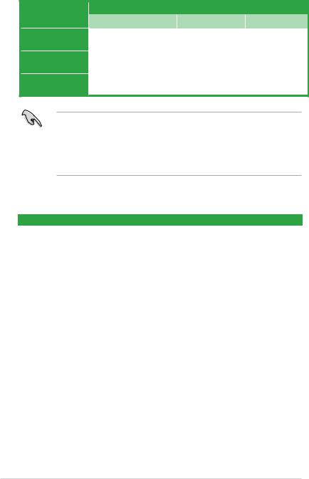
1.2.1Placement direction
When installing the motherboard, place it into the chassis in the correct orientation. The edge with external ports goes to the rear part of the chassis as indicated in the image.
1.2.2Screw holes
Place nine screws into the holes indicated by circles to secure the motherboard to the chassis.
Do not overtighten the screws! Doing so can damage the motherboard.
ASUS Z170 PRO GAMING/AURA |
1-1 |

Place this side towards the rear of the chassis
1.2.3Motherboard layout
1 |
2 |
3 |
2 |
4 |
5 |
KBMS _USB1314
| <![if ! IE]> <![endif]>HDMI |
<![if ! IE]> <![endif]>DP |
ASM 1442K
| <![if ! IE]> <![endif]>DVI |
<![if ! IE]> <![endif]>VGA |
EATX12V |
USB3_3456 |
|
|
|
|
|
|
|
|
|
|
|
|
|
|
USB3.1_EC1 |
ASM |
|||
|
|
1542 |
||
|
|
|
|
ASM |
LAN_USB3.1_EA1 |
|
|
1142 |
|
|
AUDIO |
CHA_FAN1 |
|
23 |
|
PCIEX1_1 |
|
22 |
|
|
|
|
Intel |
|
|
23 |
I219V |
|
PCIEX16_1 |
|
|
|
|
22 |
|
|
|
23 |
|
|
|
|
Super |
PCIEX1_2 |
BATTERY |
|
I/O |
||
|
|
|
22 |
PCIEX16_2 |
|
|
ALC |
|
1150 |
|
COVER |
PCIEX1_3 |
SupremeFX LED |
|
21 |
|
|
PCIEX16_3 |
AAFP |
COM |
CHA_FAN2 |
TPM |
|
|

 3D MOUNT
20 |
19 |
18 |
2 |
17 |
24.4cm(9.6in) |
|
|
|
|
|
|
|
|
CPU_FAN |
|
|
|
RGBLED |
|
6 |
DIGI |
CPU_OPT |
|
|
|
|
|
|
+VRM |
|
|
|
|
|
|
|
|
|
|
|
|
BOOT_DEVICE_LED |
|
|
|
|
|
|
|
VGA_LED |
|
|
|
|
|
|
|
DRAM_LED |
|
|
|
<![if ! IE]> <![endif]>288-pin module) |
<![if ! IE]> <![endif]>288-pin module) |
<![if ! IE]> <![endif]>288-pin module) |
<![if ! IE]> <![endif]>288-pin module) |
CPU_LED |
|
|
|
|
<![if ! IE]> <![endif]>30.5cm(12in) |
1 |
||||
|
<![if ! IE]> <![endif]>DIMMDDR4A1 (64bit, |
<![if ! IE]> <![endif]>DIMMDDR4A2 (64bit, |
<![if ! IE]> <![endif]>DIMMDDR4B1 (64bit, |
<![if ! IE]> <![endif]>DIMMDDR4B2 (64bit, |
<![if ! IE]> <![endif]>FAN3CHA |
2 |
|
LGA1151 |
|
|
|
|
<![if ! IE]> <![endif]>EATXPWR |
|
|
|
|
|
|
|
|
|
|
|
|
|
|
|
<![if ! IE]> <![endif]>12 |
|
7 |
|
|
|
|
|
<![if ! IE]> <![endif]>USB3 |
|
|
|
|
|
|
|
|
|
Intel®
Z170
22110 |
2280 |
2260 |
2242 |
TPU
128Mb BIOS
SB_PWR
USB78 |
USB910 |
CLRTC |
T_SENSOR |
ROG_EXT |
|
EXT_FAN CPU_OV |
|
USB1112
<![endif]>SATA6G_56 SATA6G_34 SATA6G_12
<![if ! IE]><![endif]>
 M.2(SOCKET3)
PANEL
8
9
10
16 |
15 |
14 13 |
2 |
12 |
11 |
1-2 |
Chapter 1: Product introduction |
1.2.4Layout contents
Connectors/Jumpers/Slots/LED |
Page |
|
1. |
ATX power connectors (24-pin EATXPWR, 8-pin ATX12V) |
1-19 |
2. |
CPU, CPU optional, extension, and chassis fan connectors (4-pin CPU_FAN, |
1-18 |
|
4-pin CPU_OPT, 5-pin EXT_FAN, 4-pin CHA_FAN1~3) |
|
3. |
Intel® LGA1151 CPU socket |
1-3 |
4. |
DDR4 DIMM slots |
1-8 |
5. |
Q LEDs (BOOT_DEVICE_LED, VGA_LED, DRAM_LED, CPU_LED) |
1-26 |
6. |
RGB LED |
1-26 |
7. |
USB 3.0 connector (20-1 pin USB3_12) |
1-21 |
8. |
Intel® Z170 Serial ATA 6.0 Gb/s connector (7-pin SATA6G_1~6) |
1-22 |
9. |
M.2 Socket 3 |
1-24 |
10. |
Thermal sensor connector (2-pin T_SENSOR) |
1-19 |
11. |
System panel connector (20-5 pin PANEL) |
1-23 |
12. |
CPU Over Voltage jumper (3-pin CPU_OV) |
1-14 |
13. |
Clear RTC RAM (2-pin CLRTC) |
1-13 |
14. |
Standby Power LED (SB_PWR) |
1-25 |
15. |
USB 2.0 connectors (10-1 pin USB78, USB910, USB1112) |
1-24 |
16. |
ROG Extension connector (18-1 pin ROG_EXT) |
1-20 |
17. |
TPM connector (14-1 pin TPM) |
1-17 |
18. |
Serial port connectors (10-1 pin COM) |
1-17 |
19. |
Front panel audio connector (10-1 pin AAFP) |
1-20 |
20. |
3D Mount holes |
1-14 |
21. |
SupremeFX LED |
1-25 |
22. |
PCI Express 3.0 x16 slots |
1-11 |
23. |
PCI Express 3.0 x1 slots |
1-11 |
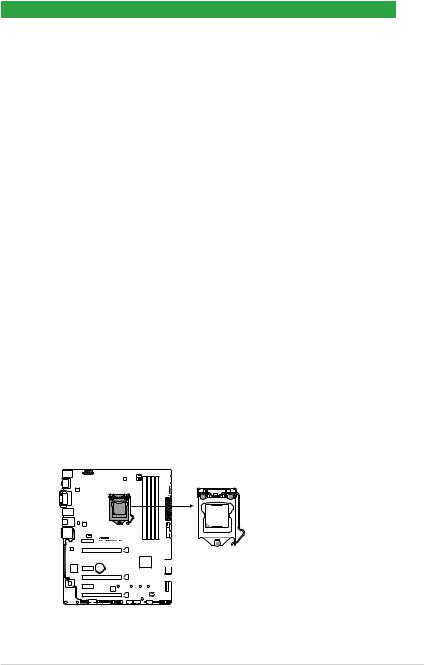
1.3Central Processing Unit (CPU)
This motherboard comes with a surface mount LGA1151 socket designed for 6th Generation Intel® Core™ i7 / i5 / i3, Pentium®, and Celeron® processors.
Z170 PRO GAMING/AURA CPU socket LGA1151
ASUS Z170 PRO GAMING/AURA |
1-3 |
Unplug all power cables before installing the CPU.
•Ensure that you install the correct CPU designed for the LGA1151 socket only. DO
NOT install a CPU designed for LGA1150, LGA1155 and LGA1156 sockets on the
LGA1151 socket.
•Upon purchase of the motherboard, ensure that the PnP cap is on the socket and the socket contacts are not bent. Contact your retailer immediately if the PnP cap is missing, or if you see any damage to the PnP cap/socket contacts/motherboard components.
•Keep the cap after installing the motherboard. ASUS will process Return Merchandise Authorization (RMA) requests only if the motherboard comes with the cap on the LGA1151 socket.
•The product warranty does not cover damage to the socket contacts resulting from incorrect CPU installation/removal, or misplacement/loss/incorrect removal of the PnP cap.
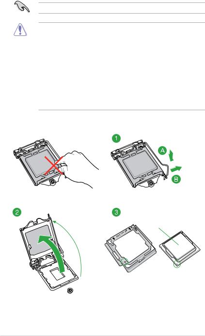
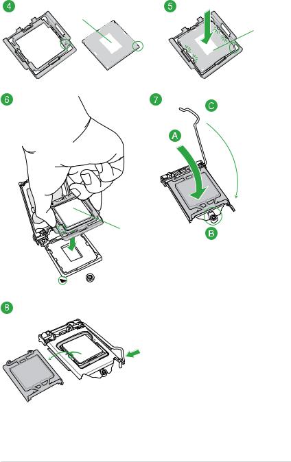
1.3.1Installing the CPU
Top of CPU
1-4 |
Chapter 1: Product introduction |
Bottom of CPU
Bottom of CPU
Top of CPU
ASUS Z170 PRO GAMING/AURA |
1-5 |
WARNING!
•Ensure that the CPU is firmly clicked into place before installing it onto the CPU socket on the motherboard.
•Use the CPU Installation Tool for installing the CPU only. DO NOT damage or bend the CPU Installation Tool.
•Always firmly hold both sides of the CPU Installation Tool when installing, removing, or picking up the CPU Installation Tool.
•ASUS will not cover damages resulting from incorrect CPU installation/removal, incorrect CPU orientation/placement, or other damages resulting from negligence by the user.
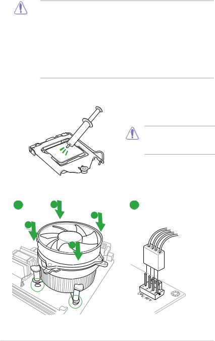
1.3.2CPU heatsink and fan assembly installation
Apply the Thermal Interface Material to the CPU heatsink and CPU before you install the heatsink and fan if necessary.
To install the CPU heatsink and fan assembly
1 A 2
B
B
A
1-6 |
Chapter 1: Product introduction |
3 |
4 |
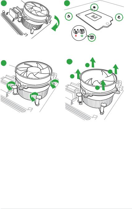
To uninstall the CPU heatsink and fan assembly
1 |
2 |
A
 B B
B B 
A
ASUS Z170 PRO GAMING/AURA |
1-7 |
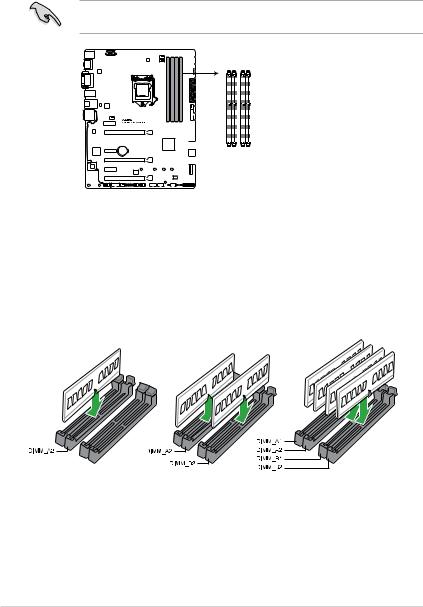
1.4System memory
1.4.1Overview
This motherboard comes with four Double Data Rate 4 (DDR4) Dual Inline Memory Module (DIMM) sockets. A DDR4 module is notched differently from a DDR, DDR2, or DDR3 module. DO NOT install a DDR, DDR2, or DDR3 memory module to the DDR4 slot.
According to Intel® CPU spec, DIMM voltage below 1.65 V is recommended to protect the CPU.
| <![if ! IE]> <![endif]>DIMM A1 |
<![if ! IE]> <![endif]>DIMM A2 |
<![if ! IE]> <![endif]>DIMM B1 |
<![if ! IE]> <![endif]>DIMM B2 |
Z170 PRO GAMING/AURA 288-pin DDR4 DIMM sockets
1.4.2Memory configurations
You may install 2 GB, 4 GB, 8 GB, and 16 GB unbuffered non-ECC DDR4 DIMMs into the DIMM sockets. You can refer to the recommended memory population below.
Recommended memory configurations
1-8 |
Chapter 1: Product introduction |
•You may install varying memory sizes in Channel A and Channel B. The system maps
the total size of the lower-sized channel for the dual-channel configuration. Any excess memory from the higher-sized channel is then mapped for single-channel operation.
•According to Intel® CPU spec, DIMM voltage below 1.65V is recommended to protect the CPU.
•Due to the memory address limitation on 32-bit Windows® OS, when you install 4GB or more memory on the motherboard, the actual usable memory for the OS can be about 3GB or less. For effective use of memory, we recommend that you do any of the following:
-Use a maximum of 3 GB system memory if you are using a 32-bit Windows® OS.
-Install a 64-bit Windows® OS if you want to install 4GB or more on the motherboard.
-For more details, refer to the Microsoft® support site at http://support.microsoft. com/kb/929605/en-us.
•The default memory operation frequency is dependent on its Serial Presence Detect (SPD), which is the standard way of accessing information from a memory module. Under the default state, some memory modules for overclocking may operate at a lower frequency than the vendor-marked value. To operate at the vendor-marked or at a higher frequency, refer to section 2.5 Ai Tweaker menu for manual memory frequency adjustment.
•Always install the DIMMS with the same CAS Latency. For an optimum compatibility, we recommend that you install memory modules of the same version or data code (D/C) from the same vendor. Check with the vendor to get the correct memory modules.
•We highly recommend to use 4-DIMM/2-DIMM kit for full DIMM configuration. Full DIMM support is subject to the physical characteristics of individual CPUs or Memory.
•For system stability, use a more efficient memory cooling system to support a full memory load (4 DIMMs) or overclocking condition.
ASUS Z170 PRO GAMING/AURA |
1-9 |
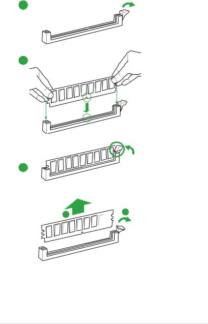
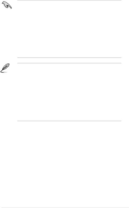
1.4.3Installing a DIMM
1
2
3
To remove a DIMM
B 
 A
A
1-10 |
Chapter 1: Product introduction |
1.5Expansion slots
In the future, you may need to install expansion cards. The following sub sections describe the slots and the expansion cards that they support.
Unplug the power cord before adding or removing expansion cards. Failure to do so may cause you physical injury and damage motherboard components.
1.5.1Installing an expansion card
To install an expansion card:
1.Before installing the expansion card, read the documentation that came with it and make the necessary hardware settings for the card.
2.Remove the system unit cover (if your motherboard is already installed in a chassis).
3.Remove the bracket opposite the slot that you intend to use. Keep the screw for later use.
4.Align the card connector with the slot and press firmly until the card is completely seated on the slot.
5.Secure the card to the chassis with the screw you removed earlier.
6.Replace the system cover.
1.5.2Configuring an expansion card
After installing the expansion card, configure it by adjusting the software settings.
1.Turn on the system and change the necessary BIOS settings, if any. See Chapter 2 for information on BIOS setup.
2.Assign an IRQ to the card.
3.Install the software drivers for the expansion card.
When using PCI cards on shared slots, ensure that the drivers support “Share IRQ” or that the cards do not need IRQ assignments. Otherwise, conflicts will arise between the two PCI groups, making the system unstable and the card inoperable.
1.5.3PCI Express 3.0 x1 slots
This motherboard supports PCI Express 3.0 x1 network cards, SCSI cards, and other cards that comply with the PCI Express specifications.
1.5.4PCI Express 3.0 x16 slots
This motherboard has three PCI Express 3.0 x16 slots that support PCI Express 3.0 x16 graphic cards complying with the PCI Express specifications.
ASUS Z170 PRO GAMING/AURA |
1-11 |
VGA configuration
Single VGA/PCIe card
Dual VGA/PCIe cards
Triple VGA/PCIe cards
PCI Express operating mode |
|
||
PCIe 3.0 x16_1 |
PCIe 3.0 x16_2 |
PCIe 3.0 x16_3 |
|
|
|
|
|
x16 (Recommended for |
N/A |
N/A |
|
single VGA card) |
|||
|
|
||
|
|
|
|
x8 |
x8 |
N/A |
|
|
|
|
|
x8 |
x8 |
x4 |
|
|
|
|
|
• In single VGA card mode, use the PCIe 3.0 x16_1 slot for a PCI Express x16 graphics card to get better performance.
•We recommend that you provide sufficient power when running SLI™ or CrossFireX™ mode. See page 1-19 for details.
•Connect a chassis fan to the motherboard connector labeled CHA_FAN1/2/3 when using multiple graphics cards for better thermal environment.
IRQ assignments for this motherboard
|
A |
B |
C |
D |
PCIE x16_1 |
Shared |
– |
– |
– |
PCIE x16_2 |
– |
Shared |
– |
– |
ASM1142 |
Shared |
– |
– |
– |
PCIE x1_1 |
– |
– |
Shared |
– |
LAN I219V |
Shared |
– |
– |
– |
PCIE x16_3 |
Shared |
– |
– |
– |
M.2(X4) |
Shared |
– |
– |
– |
PCIE x1_3 |
|
|
Shared |
|
PCIE x1_2 |
|
|
|
Shared |
XHCI Controller |
Shared |
– |
– |
– |
SATA Controller |
Shared |
– |
– |
– |
HD Audio Controller |
Shared |
– |
– |
– |
|
|
|
|
|
1-12 |
Chapter 1: Product introduction |
1.6Headers / Jumpers / Holes
1.Clear RTC RAM (2-pin CLRTC)
This header allows you to clear the Real Time Clock (RTC) RAM in CMOS. You can clear the CMOS memory of date, time, and system setup parameters by erasing the CMOS RTC RAM data. The onboard button cell battery powers the RAM data in CMOS, which include system setup information such as system passwords.
CLRTC
<![if ! IE]><![endif]>+3V_BAT GND
PIN 1
Z170 PRO GAMING/AURA Clear RTC RAM
To erase the RTC RAM:
1. Turn OFF the computer and unplug the power cord.
2. Use a metal object such as a screwdriver to short the two pins. 3. Plug the power cord and turn ON the computer.
4. Hold down the <Del> key during the boot process and enter BIOS setup to reenter data.
• If the steps above do not help, remove the onboard battery and short the two pins again to clear the CMOS RTC RAM data. After clearing the CMOS, reinstall the battery.
• You do not need to clear the RTC when the system hangs due to overclocking. For system failure due to overclocking, use the CPU Parameter Recall (C.P.R.) feature. Shut down and reboot the system, then the BIOS automatically resets parameter settings to default values.
ASUS Z170 PRO GAMING/AURA |
1-13 |
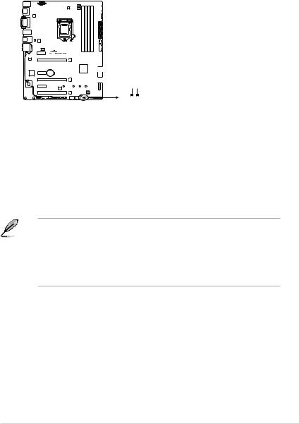
2.CPU Over Voltage jumper (3-pin CPU_OV)
The CPU Over Voltage jumper allows you to set a higher CPU voltage for a flexible overclocking system, depending on the type of the installed CPU. To gain more CPU voltage setting, insert the jumper to pins 2-3. To go back to its default CPU voltage setting, insert the jumper to pins 1-2.
CPU_OV
|
|
|
|
|
1 |
2 |
2 |
3 |
||
|
||||||||||
|
|
|
|
|
||||||
|
|
|
|
|
|
|
|
|
|
|
|
|
|
|
|
|
|
|
|
|
|
Disable Enable
(default setting)
Z170 PRO GAMING/AURA CPU_OV setting
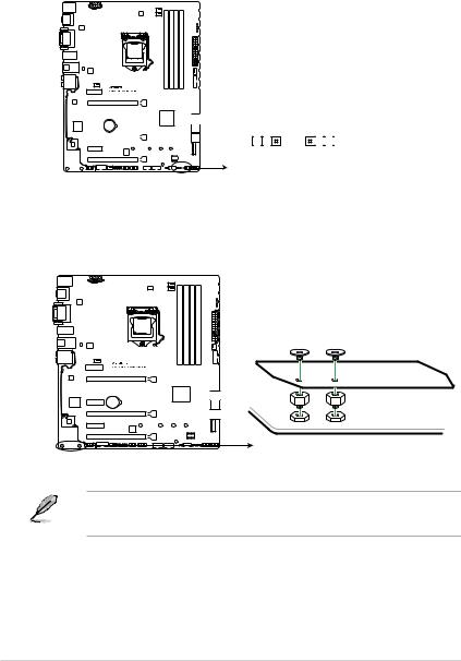
3.3D Mount holes
Create a 3D printout and secure it to these 3D Mount holes for a personalized motherboard.
3D MOUNT
Z170 PRO GAMING/AURA 3D MOUNT
• Download 3D source files at http://www.asus.com.
• Use the bundled 3D mount printing screws to install the 3D printouts.
1-14 |
Chapter 1: Product introduction |
1.7Connectors
1.7.1Rear panel connectors
1 |
2 |
3 |
4 |
5 6 |
7 |
8 |
16 |
15 |
14 |
13 |
12 |
11 10 |
9 |
1.PS/2 Mouse/Keyboard combo port. This port connects to a PS/2 mouse or PS/2 keyboard.
2.DisplayPort. This port is for a DisplayPort-compatible devices.
3.Video Graphics Adapter (VGA) port. This 15-pin port is for a VGA monitor or other VGA-compatible devices.
4.LAN (RJ-45) port. This port allows Gigabit connection to a Local Area Network (LAN) through a network hub.
LAN port LED indications
Activity/Link LED |
|
Speed LED |
||
Status |
|
Description |
Status |
Description |
Off |
|
No link |
OFF |
10 Mbps connection |
Orange |
|
Linked |
ORANGE |
100 Mbps connection |
Orange |
|
Data activity |
GREEN |
1 Gbps connection |
(Blinking) |
|
|
|
|
Orange (Blinking |
|
Ready to wake |
|
|
then steady) |
|
up from S5 mode |
|
|
Activity Link Speed
LED LED
LAN port
5.Center / Subwoofer port (orange). This port connects the center/subwoofer speakers.
6.Rear Speaker Out port (black). This port connects the rear speakers in a 4.1 channel, 5.1 channel, or 7.1 channel audio configuration.
7.Line In port (light blue). This port connects to the tape, CD, DVD player, or other audio sources.
8.Line Out port (lime). This port connects to a headphone or a speaker. In the 4.1, 5.1, and 7.1 channel configurations, the function of this port becomes Front Speaker Out.
9.Microphone port (pink). This port connects to a microphone.
ASUS Z170 PRO GAMING/AURA |
1-15 |
Audio 2, 4.1, 5.1, or 7.1-channel configuration
Port |
Headset |
4.1-channel |
5.1-channel |
7.1-channel |
|
2-channel |
|||||
|
|
|
|
||
Light Blue |
Line In |
Line In |
Line In |
Side Speaker Out |
|
Lime |
Line Out |
Front Speaker Out |
Front Speaker Out |
Front Speaker Out |
|
Pink |
Mic In |
Mic In |
Mic In |
Mic In |
|
Orange |
– |
– |
Center/Subwoofer |
Center/Subwoofer |
|
Black |
– |
Rear Speaker Out |
Rear Speaker Out |
Rear Speaker Out |
10.Optical S/PDIF out port. This port allows you to connect your PC to amplified speakers, headphones, or Sony/Phillips Digital Interconnect Format (S/PDIF) compliant devices.
11.USB 3.1 Type A port. This 9-pin Universal Serial Bus (USB) Type A port is for USB 3.1 devices.
12.USB 3.1 Type C port. This Universal Serial Bus (USB) Type C port is for USB 3.1 mobile or peripheral devices.
13.USB 3.0 ports 3~6. These 9-pin Universal Serial Bus (USB) ports are for USB 3.0 devices.
• We strongly recommend that you connect USB 3.0 devices to USB 3.0 ports for faster and better performance from your USB 3.0 devices.
•Due to the design of the Intel® 100 series chipset, all USB devices connected to the USB 2.0 and USB 3.0 ports are controlled by the xHCI controller. Some legacy USB devices must update their firmware for better compatibility.
14.DVI-D port. This port is for any DVI-D compatible device.
DVI-D can not be converted to output from RGB Signal to CRT and is not compatible with DVI-I.
15.HDMI port. This port is for a High-Definition Multimedia Interface (HDMI) connector, and is HDCP compliant allowing playback of HD DVD, Blu-ray, and other protected content.
• Multi-VGA output supports up to three displays under Windows® OS environment, two displays under BIOS, and one display under DOS.
•Intel display architecture design supports the following maximum supported pixel clocks (Pixel Clock = H total x V Total x Frame Rate (Screen refresh rate)):
-DisplayPort port: 553 MHz
-DVI port: 165 MHz
-VGA port: 180 MHz
-HDMI port: 300 MHz
16.USB 2.0 ports 13 and 14. These two 4-pin Universal Serial Bus (USB) ports are for USB 2.0/1.1 devices.
1-16 |
Chapter 1: Product introduction |
1.7.2Internal connectors
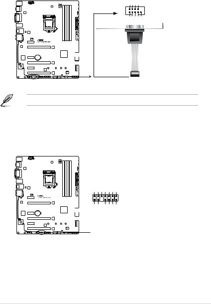
1.Serial port connector (10-1 pin COM)
This connector is for a serial (COM) port. Connect the serial port module cable to this connector, then install the module to a slot opening at the back of the system chassis.
COM
<![if ! IE]><![endif]>CTS
<![if ! IE]><![endif]>DSR
<![if ! IE]><![endif]>DTR
<![if ! IE]><![endif]>RXD
PIN 1 |
<![if ! IE]> <![endif]>DCD TXD GND RTS RI |
|
Z170 PRO GAMING/AURA Serial port (COM) connector
The COM module is purchased separately.
2.TPM connector (14-1 pin TPM)
This connector supports a Trusted Platform Module (TPM) system, which securely store keys, digital certificates, passwords and data. A TPM system also helps enhance the network security, protects digital identities, and ensures platform integrity.
TPM
<![if ! IE]><![endif]>CLKRUN_F SERIRQ_F FRAME#_F LAD3_F LAD2_F LAD1_F LAD0_F
PIN 1
<![if ! IE]><![endif]> S __C _PCIRST#_PCICLK +3VSBTBDGNDTPM+3V+3V
Z170 PRO GAMING/AURA TPM connector
ASUS Z170 PRO GAMING/AURA |
1-17 |
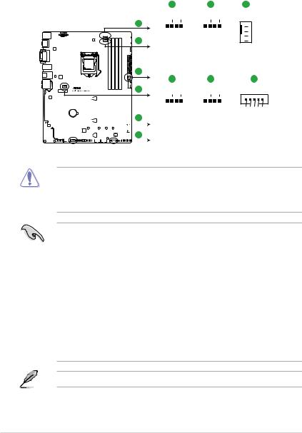
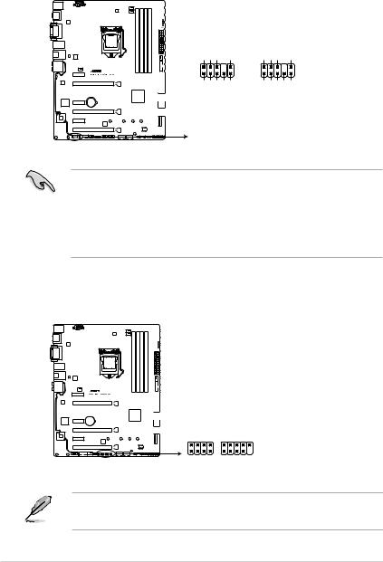
3.CPU, CPU optional, extension, and chassis fan connectors (4-pin CPU_FAN; 4-pin CPU_OPT; 5-pin EXT_FAN, 4-pin CHA_FAN1~3)
Connect the fan cables to the fan connectors on the motherboard, ensuring that the black wire of each cable matches the ground pin of the connector.
A B C
CPU_FAN CPU_OPT CHA_FAN3
A
B
C
D
|
|
|
|
|
|
|
|
|
|
|
|
|
|
|
|
|
|
|
|
|
|
|
|
|
|
|
|
|
|
|
|
|
|
|
|
|
|
|
|
|
|
| <![if ! IE]> <![endif]>CPU FAN PWM CPU FAN IN CPU FAN PWR GND |
<![if ! IE]> <![endif]>CPU FAN PWM CPU FAN IN CPU FAN PWR GND |
|||||||||||||||||||
|
|
|
D |
|
|
|
E |
|||||||||||||
CHA_FAN1 CHA_FAN2


 GND
GND
 CHA FAN PWR


 CHA FAN IN
  +5V
+5V
F
EXT_FAN
|
|
|
|
|
|
|
|
|
|
|
|
|
|
|
|
|
|
|
|
|
|
|
|
|
|
|
|
|
|
|
|
|
|
|
|
|
|
|
|
|
|
|
|
|
|
|
|
|
|
|
|
|
|
|
|
|
|
|
|
|
|
|
|
|
|
|
|
|
|
|
|
|
|
|
|
|
|
|
|
|
|
|
|
|
|
|
|
|
|
|
|
|
|
|
|
|
|
|
|
|
|
|
|
|
|
|
|
|
|
|
|
|
|
|
|
|
|
|
|
|
|
|
|
|
|
|
|
|
|
|
|
|
F |
|
<![if ! IE]> <![endif]>+5V FANCHAIN PWRFANCHA GND |
<![if ! IE]> <![endif]>+5V FANCHAIN PWRFANCHA GND |
|||||||||||||||||||
|
|
|
|
|
|
|
|
|
|
|
|
|
|
|
|
|
|
|
|
|
|
|
|
|
|
|
|
|
E |
|
|
|
|
|
|
|
|
|
|
|
|
|
|
|
|
|
|
|
|
|
|
|
|
|
|
|
|
|
|
|
|
|
|
|
|
|
|
|
|
|
|
|
|
|
|
|
|
|
|
|
|
|
|
|
|
|
|
|
|
|
|
|
|
|
|
|
|
|
|
|
|
|
|
Z170 PRO GAMING/AURA Fan connectors
PIN 1
<![if ! IE]><![endif]>GND
<![if ! IE]><![endif]>EXTFAN_SMB_DATA
<![if ! IE]><![endif]>EXTFAN_SMB_CLK
<![if ! IE]><![endif]>FANCARD_DETECT
<![if ! IE]><![endif]>EXTFAN_DET
•Do not forget to connect the fan cables to the fan connectors. Insufficient air flow inside the system may damage the motherboard components. These are not jumpers! Do not place jumper caps on the fan connectors!
•Ensure that the CPU fan cable is securely installed to the CPU fan connector.
•The CPU_FAN connector supports a CPU fan of maximum 1 A (12 W) fan power.
•The CPU_FAN connector and CHA_FAN connectors support the ASUS FAN Xpert 3 feature.
•The EXT_FAN connector supports 2 of 5 thermal sensor sources.
•The CPU fan connector detects the type of CPU fan installed and automatically switches the control modes. To configure the CPU fan’s control mode, go to
Advanced > Monitor > Q-Fan Configuration > CPU Q-Fan Control item in BIOS.
•The chassis fan connectors support DC and PWM modes. To set these fans to DC or PWM, go to Advanced > Monitor > Q-Fan Configuration > Chassis Fan 1/2/3 Q-Fan Control items in BIOS.
•The extension fan connectors support DC and PWM modes. To set these fans to DC or PWM, go to Advanced > Monitor > Q-Fan Configuration > Extension Fan 1/2/3 Q-Fan Control items in BIOS.
The FAN EXTENSION CARD is purchased separately.
1-18 |
Chapter 1: Product introduction |
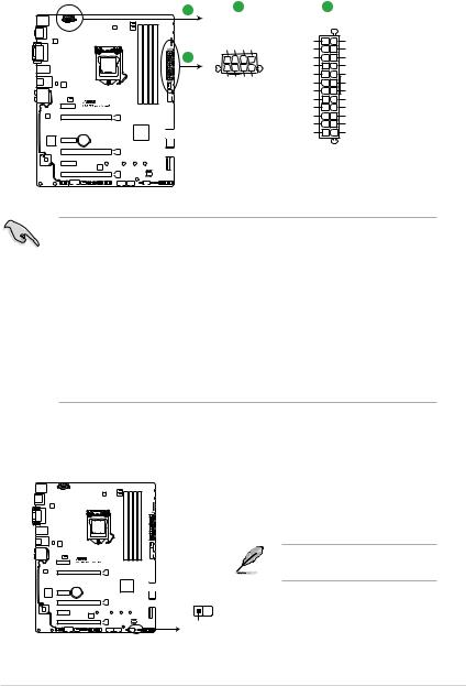
4.ATX power connectors (24-pin EATXPWR, 8-pin ATX12V)
These connectors are for ATX power supply plugs. The power supply plugs are designed to fit these connectors in only one orientation. Find the proper orientation and push down firmly until the connectors completely fit.
A |
A |
|
|
|
B |
|
|
|
|
|
|
|
|
EATX12V |
|
EATXPWR |
||||
| <![if ! IE]> <![endif]>GND |
<![if ! IE]> <![endif]>GND GND |
<![if ! IE]> <![endif]>GND |
+3 Volts |
GND |
||
|
|
|
|
|||
PIN 1 |
|
|
|
+12 |
Volts |
+5 Volts |
B |
|
|
|
+12 |
Volts |
+5 Volts |
|
|
|
|
+5V Standby |
+5 Volts |
|
| <![if ! IE]> <![endif]>DC |
<![if ! IE]> <![endif]>DC DC |
<![if ! IE]> <![endif]>DC |
Power OK |
-5 Volts |
||
|
GND |
GND |
||||
| <![if ! IE]> <![endif]>+12V |
<![if ! IE]> <![endif]>+12V |
<![if ! IE]> <![endif]>+12V |
<![if ! IE]> <![endif]>+12V |
+5 Volts |
GND |
|
|
GND |
GND |
||||
|
|
|
|
|
||
|
|
|
|
+5 Volts |
PSON# |
|
|
|
|
|
|
GND |
GND |
|
|
|
|
+3 |
Volts |
-12 Volts |
|
|
|
|
+3 |
Volts |
+3 Volts |
|
|
|
|
|
PIN 1 |
|
Z170 PRO GAMING/AURA ATX power connectors
•For a fully configured system, we recommend that you use a power supply unit
(PSU) that complies with ATX 12 V Specification 2.0 (or later version) and provides a minimum power of 350 W.
•DO NOT forget to connect the 4-pin/8-pin ATX +12V power plug. Otherwise, the system will not boot up.
•We recommend that you use a PSU with higher power output when configuring a system with more power-consuming devices or when you intend to install additional devices. The system may become unstable or may not boot up if the power is inadequate.
•If you are uncertain about the minimum power supply requirement for your system, refer to the Recommended Power Supply Wattage Calculator at http://support.asus. com/PowerSupplyCalculator/PSCalculator.aspx?SLanguage=en-us for details.
5.Thermal sensor connector (2-pin T_SENSOR)
This connector is for the thermistor cable that allows you to monitor the temperature of your motherboard’s critical components and connected devices.
The thermistor cable is purchased separately.
T_SENSOR
 GND
GND
PIN 1
SENSOR IN
Z170 PRO GAMING/AURA T_SENSOR connector
ASUS Z170 PRO GAMING/AURA |
1-19 |
6.Front panel audio connector (10-1 pin AAFP)
This connector is for a chassis-mounted front panel audio I/O module that supports either HD Audio or legacy AC`97 audio standard. Connect one end of the front panel audio I/O module cable to this connector.
| <![if ! IE]> <![endif]>AGND NC SENSE1 RETUR |
<![if ! IE]> <![endif]>SENSE2 RETUR |
AAFP |
|
| <![if ! IE]> <![endif]>PORT1 L PORT1 R PORT2 R SENSE SEND PORT2 L |
|
HD-audio-compliant
pin definition
| <![if ! IE]> <![endif]>AGND NC NC |
<![if ! IE]> <![endif]>NC |
PIN 1
<![if ! IE]><![endif]>Line out_L
<![if ! IE]><![endif]>NC
<![if ! IE]><![endif]>Line out_R
<![if ! IE]><![endif]>MICPWR
<![if ! IE]><![endif]>MIC2
Legacy AC’97 compliant definition
Z170 PRO GAMING/AURA Front panel audio connector
•We recommend that you connect a high-definition front panel audio module to this
connector to avail of the motherboard’s high-definition audio capability.
•If you want to connect a high-definition front panel audio module to this connector, set the Front Panel Type item in the BIOS setup to [HD]. If you want to connect an AC’97 front panel audio module to this connector, set the item to [AC97]. By default, this connector is set to [HD]. See section 2.6.8 Onboard Devices Configuration for details.
7.ROG Extension - ROG_EXT connector (18-1 pin ROG_EXT)
This connector is for the Front Base.
ROG_EXT
Z170 PRO GAMING/AURA ROG_EXT connectors
• The Front Base is purchased separately.
• Visit www.asus.com for more information about the Front Base.
1-20 |
Chapter 1: Product introduction |
 Loading...