


TUF GAMING
X570-PLUS
Motherboard

E15235
First Edition V1
May 2019
Copyright © 2019 ASUSTeK COMPUTER INC. All Rights Reserved.
No part of this manual, including the products and software described in it, may be reproduced,
transmitted, transcribed, stored in a retrieval system, or translated into any language in any form or by any
means, except documentation kept by the purchaser for backup purposes, without the express written
permission of ASUSTeK COMPUTER INC. (“ASUS”).
Product warranty or service will not be extended if: (1) the product is repaired, modied or altered, unless
such repair, modication of alteration is authorized in writing by ASUS; or (2) the serial number of the
product is defaced or missing.
ASUS PROVIDES THIS MANUAL “AS IS” WITHOUT WARRANTY OF ANY KIND, EITHER EXPRESS
OR IMPLIED, INCLUDING BUT NOT LIMITED TO THE IMPLIED WARRANTIES OR CONDITIONS OF
MERCHANTABILITY OR FITNESS FOR A PARTICULAR PURPOSE. IN NO EVENT SHALL ASUS, ITS
DIRECTORS, OFFICERS, EMPLOYEES OR AGENTS BE LIABLE FOR ANY INDIRECT, SPECIAL,
INCIDENTAL, OR CONSEQUENTIAL DAMAGES (INCLUDING DAMAGES FOR LOSS OF PROFITS,
LOSS OF BUSINESS, LOSS OF USE OR DATA, INTERRUPTION OF BUSINESS AND THE LIKE),
EVEN IF ASUS HAS BEEN ADVISED OF THE POSSIBILITY OF SUCH DAMAGES ARISING FROM ANY
DEFECT OR ERROR IN THIS MANUAL OR PRODUCT.
SPECIFICATIONS AND INFORMATION CONTAINED IN THIS MANUAL ARE FURNISHED FOR
INFORMATIONAL USE ONLY, AND ARE SUBJECT TO CHANGE AT ANY TIME WITHOUT NOTICE,
AND SHOULD NOT BE CONSTRUED AS A COMMITMENT BY ASUS. ASUS ASSUMES NO
RESPONSIBILITY OR LIABILITY FOR ANY ERRORS OR INACCURACIES THAT MAY APPEAR IN THIS
MANUAL, INCLUDING THE PRODUCTS AND SOFTWARE DESCRIBED IN IT.
Products and corporate names appearing in this manual may or may not be registered trademarks or
copyrights of their respective companies, and are used only for identication or explanation and to the
owners’ benet, without intent to infringe.
Offer to Provide Source Code of Certain Software
This product contains copyrighted software that is licensed under the General Public License (“GPL”),
under the Lesser General Public License Version (“LGPL”) and/or other Free Open Source Software
Licenses. Such software in this product is distributed without any warranty to the extent permitted by the
applicable law. Copies of these licenses are included in this product.
Where the applicable license entitles you to the source code of such software and/or other additional data,
you may obtain it for a period of three years after our last shipment of the product, either
(1) for free by downloading it from https://www.asus.com/support/
or
(2) for the cost of reproduction and shipment, which is dependent on the preferred carrier and the location
where you want to have it shipped to, by sending a request to:
ASUSTeK Computer Inc.
Legal Compliance Dept.
15 Li Te Rd.,
Beitou, Taipei 112
Taiwan
In your request please provide the name, model number and version, as stated in the About Box of the
product for which you wish to obtain the corresponding source code and your contact details so that we
can coordinate the terms and cost of shipment with you.
The source code will be distributed WITHOUT ANY WARRANTY and licensed under the same license as
the corresponding binary/object code.
This offer is valid to anyone in receipt of this information.
ASUSTeK is eager to duly provide complete source code as required under various Free Open Source
Software licenses. If however you encounter any problems in obtaining the full corresponding source
code we would be much obliged if you give us a notication to the email address gpl@asus.com, stating
the product and describing the problem (please DO NOT send large attachments such as source code
archives, etc. to this email address).
ii

Contents
Safety information ....................................................................................................... v
About this guide ......................................................................................................... vi
TUF GAMING X570-PLUS specications summary .............................................. viii
Package contents ...................................................................................................... xii
Installation tools and components ......................................................................... xiii
Chapter 1: Product Introduction
1.1 Motherboard overview ............................................................................... 1-1
1.1.1 Before you proceed .....................................................................1-1
1.1.2 Motherboard layout .....................................................................1-2
1.1.3 Central Processing Unit (CPU) ...................................................1-4
1.1.4 System memory ..........................................................................1-4
1.1.5 Expansion slots ...........................................................................1-6
1.1.6 Onboard LEDs ...........................................................................1-8
1.1.7 Jumpers ...................................................................................... 1-9
1.1.8 Internal connectors....................................................................1-10
Chapter 2: Basic Installation
2.1 Building your PC system...........................................................................2-1
2.1.1 Motherboard installation ..............................................................2-1
2.1.2 CPU installation...........................................................................2-3
2.1.3 CPU heatsink and fan assembly installation ............................... 2-4
2.1.4 DIMM installation.........................................................................2-6
2.1.5 ATX power connection ................................................................2-7
2.1.6 SATA device connection .............................................................2-7
2.1.7 Front I/O connector .....................................................................2-8
2.1.8 Expansion card installation .........................................................2-9
2.1.9 M.2 installation ..........................................................................2-10
2.2 Motherboard rear and audio connections ............................................. 2-11
2.2.1 Rear I/O connection ..................................................................2-11
2.2.2 Audio I/O connections ...............................................................2-12
2.3 Starting up for the rst time .................................................................... 2-15
2.4 Turning off the computer ........................................................................ 2-15
Chapter 3: BIOS Setup
3.1 Knowing BIOS ............................................................................................ 3-1
3.2 BIOS setup program .................................................................................. 3-2
3.2.1 EZ Mode......................................................................................3-3
3.2.2 Advanced Mode ..........................................................................3-4
iii

3.2.3 Q-Fan Control .............................................................................3-7
3.3 My Favorites ............................................................................................... 3-9
3.4 Main menu ................................................................................................ 3-11
3.5 Ai Tweaker menu......................................................................................3-11
3.6 Advanced menu ....................................................................................... 3-12
3.6.1 AMD fTPM Conguration ..........................................................3-12
3.6.2 CPU Conguration ....................................................................3-12
3.6.3 NB Conguration .......................................................................3-12
3.6.4 SATA Conguration ..................................................................3-13
3.6.5 Onboard Devices Conguration ................................................3-14
3.6.6 APM Conguration ....................................................................3-14
3.6.7 PCI Subsytem Settings .............................................................3-15
3.6.8 USB Conguration ....................................................................3-15
3.6.9 HDD/SSD SMART Information .................................................3-15
3.6.10 NVMe Conguration .................................................................. 3-15
3.6.11 Network Stack Conguration..................................................... 3-15
3.7 Monitor menu ........................................................................................... 3-16
3.8 Boot menu ................................................................................................ 3-16
3.9 Tool menu ................................................................................................. 3-17
3.9.1 ASUS EZ Flash 3 Utility ............................................................3-17
3.9.2 ASUS User Prole.....................................................................3-18
3.9.3 ASUS SPD Information .............................................................3-18
3.9.4 ASUS Armoury Crate ................................................................3-18
3.10 Exit menu .................................................................................................. 3-18
3.11 Updating BIOS .......................................................................................... 3-19
3.11.1 EZ Update ................................................................................. 3-19
3.11.2 ASUS EZ Flash 3 ...................................................................... 3-20
3.11.3 ASUS CrashFree BIOS 3 .......................................................... 3-22
Chapter 4: RAID Support
4.1 AMD RAID Array congurations ............................................................... 4-1
4.1.1 RAID denitions ..........................................................................4-1
Appendix
Notices .................................................................................................................... A-1
ASUS contact information ...................................................................................... A-5
iv

Safety information
Electrical safety
• To prevent electrical shock hazards, disconnect the power cable from the electrical outlet
before relocating the system.
• When adding or removing devices to or from the system, ensure that the power cables
for the devices are unplugged before the signal cables are connected. If possible,
disconnect all power cables from the existing system before you add a device.
• Before connecting or removing signal cables from the motherboard, ensure that all
power cables are unplugged.
• Seek professional assistance before using an adapter or extension cord. These devices
could interrupt the grounding circuit.
• Ensure that your power supply is set to the correct voltage in your area. If you are not
sure about the voltage of the electrical outlet you are using, contact your local power
company.
• If the power supply is broken, do not try to x it by yourself. Contact a qualied service
technician or your retailer.
Operation safety
• Before installing the motherboard and adding devices on it, carefully read all the manuals
that came with the package.
• Before using the product, ensure all cables are correctly connected and the power
cables are not damaged. If you detect any damage, contact your dealer immediately.
• To avoid short circuits, keep paper clips, screws, and staples away from connectors,
slots, sockets and circuitry.
• Avoid dust, humidity, and temperature extremes. Do not place the product in any area
where it may become wet.
• Place the product on a stable surface.
• If you encounter technical problems with the product, contact a qualied service
technician or your retailer.
v

About this guide
This user guide contains the information you need when installing and conguring the
motherboard.
How this guide is organized
This guide contains the following parts:
• Chapter 1: Product Introduction
This chapter describes the features of the motherboard and the new technology it
supports. It includes description of the switches, jumpers, and connectors on the
motherboard.
• Chapter 2: Basic Installation
This chapter lists the hardware setup procedures that you have to perform when
installing system components.
• Chapter 3: BIOS Setup
This chapter tells how to change system settings through the BIOS Setup menus.
Detailed descriptions of the BIOS parameters are also provided.
• Chapter 4: RAID Support
This chapter describes the RAID congurations.
Where to nd more information
Refer to the following sources for additional information and for product and software
updates.
1. ASUS website
The ASUS website (www.asus.com) provides updated information on ASUS hardware
and software products.
2. Optional documentation
Your product package may include optional documentation, such as warranty yers,
that may have been added by your dealer. These documents are not part of the
standard package.
vi
Conventions used in this guide
To ensure that you perform certain tasks properly, take note of the following symbols used
throughout this manual.
DANGER/WARNING: Information to prevent injury to yourself when trying to
complete a task.
CAUTION: Information to prevent damage to the components when trying to
complete a task.
IMPORTANT: Instructions that you MUST follow to complete a task.
NOTE: Tips and additional information to help you complete a task.
Typography
Bold text
Italics
<Key> Keys enclosed in the less-than and greater-than sign
<Key1> + <Key2> + <Key3> If you must press two or more keys simultaneously, the key
Indicates a menu or an item to select.
Used to emphasize a word or a phrase.
means that you must press the enclosed key.
Example: <Enter> means that you must press the Enter or
Return key.
names are linked with a plus sign (+).
vii
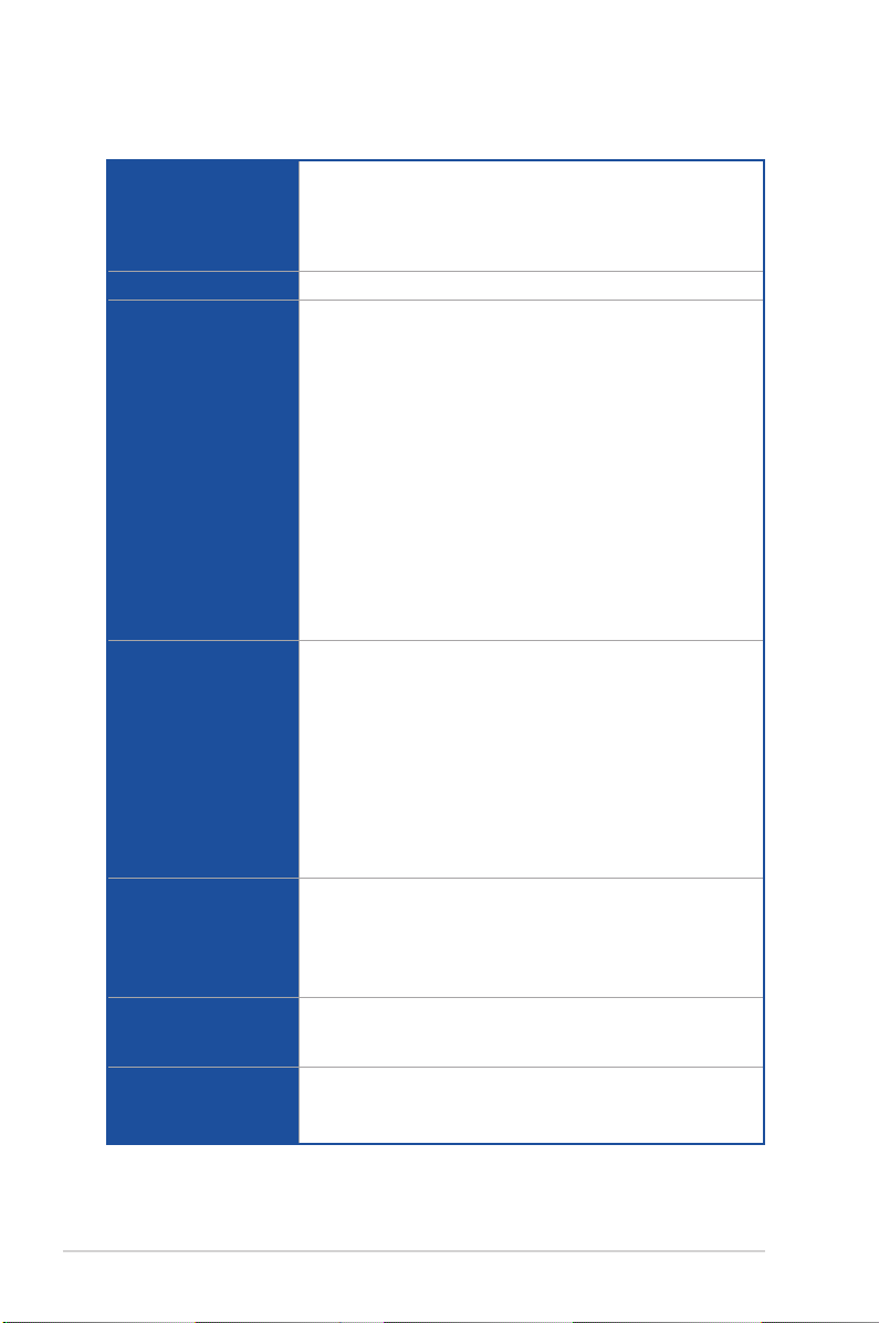
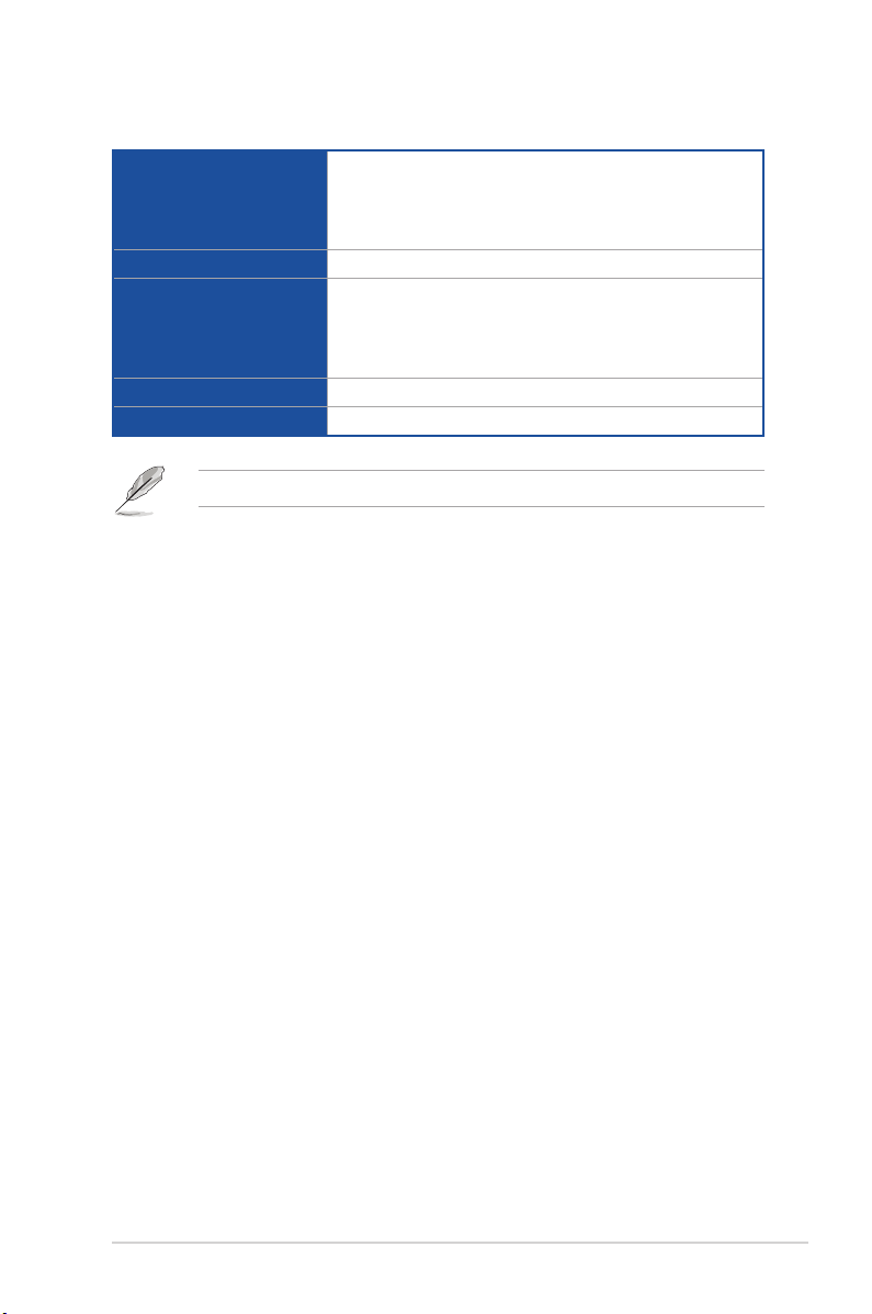
TUF GAMING X570-PLUS specications summary
AM4 socket for AMD Ryzen™ 3rd and 2nd Generation/ 2nd and 1st Gen
AMD Ryzen™ with Radeon™ Vega Graphics Processors
CPU
Chipset AMD X570 Chipset
Memory
Expansion slots
Graphics
Multi-GPU support
LAN
Supports up to 16 cores*
* Due to the CPU limitations, CPU cores supported vary by processor.
** Refer to www.asus.com for the AMD CPU support list.
AMD Ryzen™ 3rd Generation Processors
- 4 x DIMM, max. 128GB, DDR4 4400(O.C.)/3466(O.C.)/3400(O.C.)/3
200(O.C.)/3000(O.C.)/2933(O.C.)/2800(O.C.)/2666/2400/2133 MHz,
un-buffered memory
AMD Ryzen™ 2nd Generation Processors
- 4 x DIMM, max. 128GB, DDR4 3600(O.C.)/3466(O.C.)/3400(O.C.)/3
200(O.C.)/3000(O.C.)/2933(O.C.)/2800(O.C.)/2666/2400/2133 MHz,
un-buffered memory
AMD Ryzen™ 2
nd
and 1st Generation with Radeon™ Vega
Graphics Processors
- 4 x DIMM, max. 128GB, DDR4 3200(O.C.)/3000(O.C.)/2933(O.C.)/2
800(O.C.)/2666/2400/2133 MHz, un-buffered memory
Dual channel memory architecture
ECC Memory (ECC mode) support varies by CPU.
* The maximum memory frequency supported varies by processor. Refer to
www.asus.com for the Memory QVL (Qualied Vendors List).
AMD Ryzen™ 3rd Generation Processors
1 x PCIe 4.0/3.0 x16 slot (at x16 mode)
AMD Ryzen™ 2nd Generation Processors
1 x PCIe 3.0 x16 slot (at x16 mode)
AMD Ryzen™ 2
nd
and 1st Generation with Radeon™ Vega
Graphics Processors
1 x PCIe 3.0/2.0 x16 slot (at x8 mode)
AMD X570 chipset
- 1 x PCIe 4.0 x16 slot (max. at x4 mode)
- 3 x PCIe 4.0 x1 slots
Integrated Graphics in the AMD Ryzen™ 2
nd
and 1st Generation
with Radeon™ Vega Graphics
Multi-VGA output support: HDMI and DisplayPort ports
- Supports HDMI 1.4b with max. resolution of 4096 x 2160 @24Hz
- Supports DisplayPort with max. resolution of 4096 x 2304 @60Hz
AMD Ryzen™ 3rd and 2nd Generation / AMD Ryzen™ 2
nd
and 1st
Generation with Radeon™ Vega Graphics Processors
Supports AMD 2-Way CrossFireX™ Technology
Realtek® L8200A
- ASUS Turbo LAN Utility
- TUF LANGuard
viii
(continued on the next page)
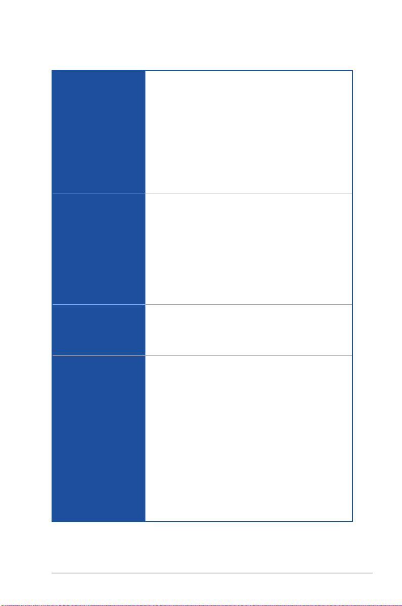
TUF GAMING X570-PLUS specications summary
AMD Ryzen™ 3rd Generation Processors
- 1 x M.2_1 socket 3 with M key, type 2242/2260/2280/ 22110
Storage
Audio
USB
ASUS Unique Features
storage devices support (SATA & PCIE 4.0 x 4 mode)
AMD Ryzen™ 2nd Generation / Ryzen™ 2
with Radeon™ Vega Graphics Processors
- 1 x M.2_1 socket 3 with M key, type 2242/2260/2280/ 22110
storage devices support (SATA & PCIE 3.0 x 4 mode)
AMD X570 Chipset:
- 1 x M.2_2 socket 3 with M key, type 2242/2260/2280/22110
storage devices support (SATA & PCIE 4.0 x 4 mode)
- 8 x SATA 6Gb/s ports
- Supports Raid 0, 1, 10
Realtek® S1200A 8-channel High Denition Audio CODEC
- Exclusive DTS Custom for GAMING Headsets
- Audio Shielding: Ensures precision analog/digital separation and
greatly reduces multi-lateral interference
- Dedicated audio PCB layers: Separate layers for left and right
channels to guard the quality of the sensitive audio signals
- Premium Japanese audio capacitors: Provide warm, natural and
immersive sound with exceptional clarity and delity
- Supports jack-detection and front panel jack-retasking
- Audio Cover: Effective shielding preserves the integrity of audio
signals to ensure best quality
- 3 x USB 3.2 Gen 2 (up to 10Gbps) ports at back panel (2 x Type-A
ports; 1 x Type-C port)
- 6 x USB 3.1 Gen 1 ports at mid-board (2 ports at mid-board, 4
ports at back panel)
- 4 x USB 2.0 ports at mid-board
ASUS TUF PROTECTION
- ASUS SafeSlot - Protect your graphics card Investment
- ASUS ESD Guard: Enhanced ESD protection
- ASUS LANGuard: Protects against LAN surges, lightning
strikes and static-electricity discharges!
- ASUS Overvoltage Protection: World-class circuit-protecting
power design
- ASUS Stainless-Steel Back I/O: 3X corrosion-resistance for
greater durability!
- ASUS DIGI+ VRM
TUF ENGINE! Power Design
- TUF Components (Choke, Cap.; certied by military-standard)
AURA
- Aura Lighting Control
- Aura RGB Strip Headers
ASUS EPU
- EPU
nd
and 1st Generation
(continued on the next page)
ix
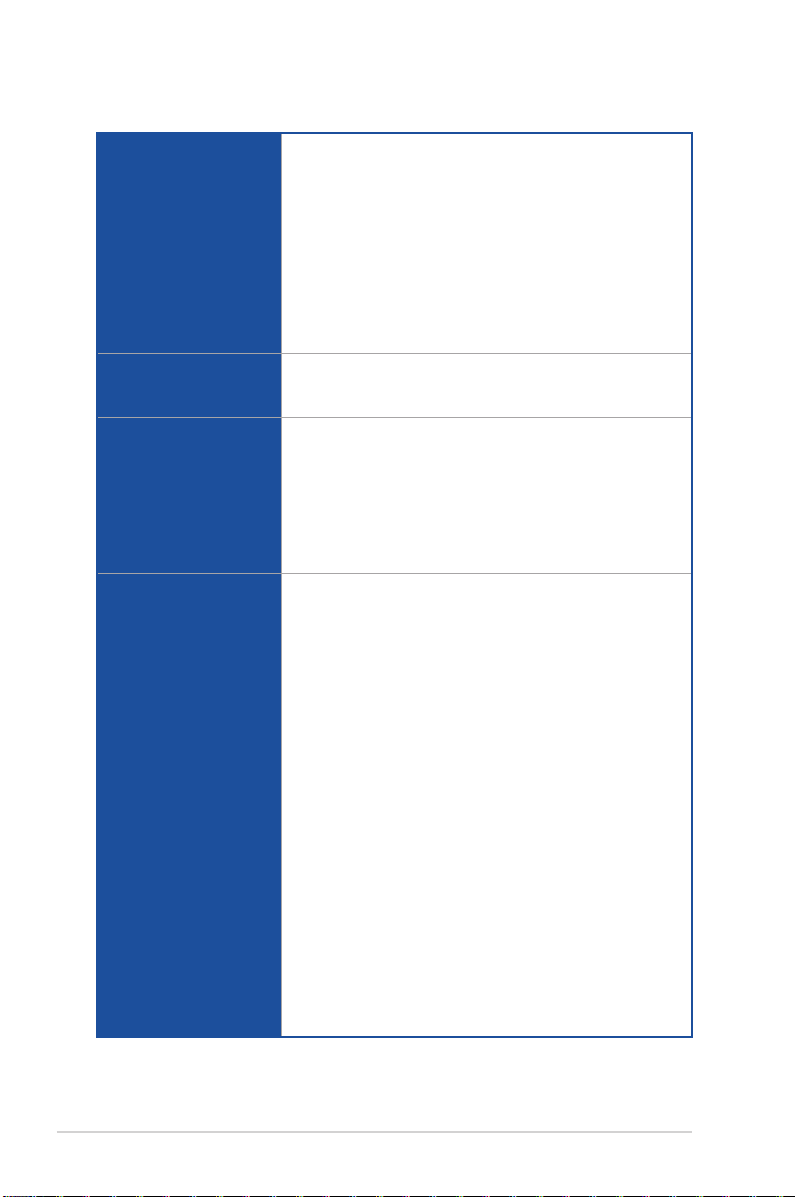
TUF GAMING X570-PLUS specications summary
ASUS Exclusive Features
- ASUS Ai Charger
- ASUS AI Suite 3
ASUS EZ DIY
ASUS Unique Features
ASUS Quiet Thermal
Solution
Back I/O Ports
Internal I/O Ports
- ASUS UEFI BIOS EZ Mode
- ASUS CrashFree BIOS 3
- ASUS EZ Flash 3
ASUS Q-Design
- ASUS Q-DIMM
- ASUS Q-Slot
- ASUS Q-LED
- ASUS FAN Xpert 4
- Stylish Design: MOS Heat-sink with dual thermal pads design,
PCH Fan, PCH and M.2 Heatsink
1 x PS/2 keyboard/ mouse combo port
1 x HDMI port
1 x DisplayPort port
1 x LAN (RJ-45) port
3 x USB 3.2 Gen 2 ports (2 x Type-A ports; 1 x Type C port)
4 x USB 3.2 Gen 1 ports
5 x Audio jacks + 1 x Optical S/PDIF out
1 x USB 3.2 Gen 1 connector supports additional 2 USB ports
2 x USB 2.0/1.1 connectors support additional 4 USB ports
8 x SATA 6 Gb/s connectors
1 x M.2_1 socket 3 with M key, type 2242/2260/2280/ 22110 storage
devices support (SATA & PCIE 4.0/3.0 x 4 mode)
1 x M.2_2 socket 3 with M key, type 2242/2260/2280/ 22110 storage
devices support (SATA & PCIE 4.0 x 4 mode)
1 x Addressable RGB Header
2 x AURA RGB headers
1 x CPU Fan connector (4-pin) for both DC mode and PWM mode
1 x CPU OPT Fan connector (4-pin)
1 x AIO_PUMP connector (4-pin)
3 x Chassis Fan connectors (4-pin) for both 3-pin (DC mode) and
4-pin (PWM mode) coolers control
1 x Front panel audio connector (AAFP)
1 x 24-pin EATX power connector
1 x 8-pin EATX 12V power connector
1 x 4-pin EATX 12V power connector
1 x System panel connector
1 x COM connector
1 x SPI_TPM header (14-1pin)
1 x Clear CMOS jumper (2-pin)
(continued on the next page)
x
TUF GAMING X570-PLUS specications summary
256Mb Flash ROM, UEFI AMI BIOS, PnP, SM BIOS 3.2, ACPI 6.2,
BIOS
Manageability WOL by PME, PXE
Support DVD contents
Operating System Support Windows® 10 64-bit
Form Factor ATX Form Factor, 12”x 9.6” (30.5 cm x 24.4 cm)
Specications are subject to change without notice.
Multi-language BIOS, ASUS EZ Flash 3, CrashFree BIOS 3, F6
Qfan Control, F3 My Favorites, F4 AURA ON/OFF, Last Modied
log, F9 Search, F12 PrintScreen, and ASUS DRAM SPD (Serial
Presence Detect) memory information
Drivers
ASUS Utilities
ASUS EZ Update
Anti-virus software (OEM version)
xi

Package contents
Check your motherboard package for the following items.
Motherboard TUF GAMING X570-PLUS
Cables 2 x SATA 6 Gb/s cables
1 x I/O shield
Accessories
Application DVD Motherboard support DVD
Documentation User guide
If any of the above items are damaged or missing, contact your retailer.
1 x M.2 screw package
1 x TUF Gaming Sticker
1 x TUF Certication card
xii
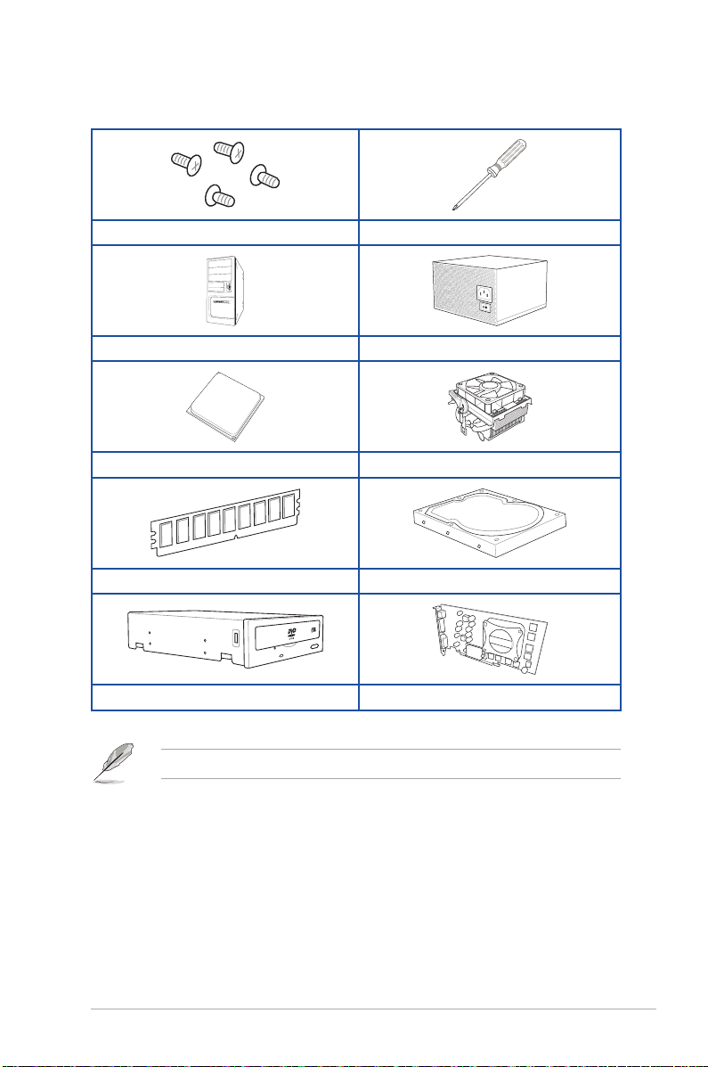
Installation tools and components
1 Bag of screws Phillips (cross) screwdriver
PC chassis Power supply unit
AMD AM4 CPU AMD AM4/AM3 compatible CPU Fan
DDR4 DIMM SATA hard disk drive
SATA optical disc drive (optional) Graphics card (optional)
The tools and components in the table above are not included in the motherboard package.
xiii

xiv

Chapter 1: Product Introduction
Product Introduction
1
1.1 Motherboard overview
1.1.1 Before you proceed
Take note of the following precautions before you install motherboard components or change
any motherboard settings.
• Unplug the power cord from the wall socket before touching any component.
• Before handling components, use a grounded wrist strap or touch a safely grounded
object or a metal object, such as the power supply case, to avoid damaging them due
to static electricity.
• Hold components by the edges to avoid touching the ICs on them.
• Whenever you uninstall any component, place it on a grounded antistatic pad or in the
bag that came with the component.
• Before you install or remove any component, ensure that the ATX power supply is
switched off or the power cord is detached from the power supply. Failure to do so
may cause severe damage to the motherboard, peripherals, or components.
Chapter 1
ASUS TUF GAMING X570-PLUS
1-1

1.1.2 Motherboard layout
Chapter 1
KBMS
_U32G1_56
U32G2
HDMI_DP
LAN_U32G2_12
_C3
U32G1_34
AUDIO
Realtek
L8200A
Super
152 3 4
EATX12V_1EATX12V_2
DIGI
+VRM
24.4cm(9.6in)
2
CPU_FAN CPU_OPT
RGB_HEADER1
BOOT_DEVICE_LED
VGA_LED
CPU_LED
DRAM_LED
6
7
8
ADD_GEN2
SOCKET AM4
DDR4 DIMM_B1 (64bit, 288-pin module)
DDR4 DIMM_B2* (64bit, 288-pin module)
DDR4 DIMM_A1 (64bit, 288-pin module)
BIOS
256Mb
CHA_FAN1
AIO_PUMP
SPI_TPM
228022110 2260 2242
PCIEX1_1
PCIEX1_2
PCIEX1_3
COM
PCIEX16_1
BATTERY
PCIEX16_2
COM_DEBUG
228022110 2260 2242
USB78 USB910
®
I/O
AAFP
M.2_1(SOCKET3)
CHA_FAN2CHA_FAN3
®
AMD
X570
M.2_2(SOCKET3)
DDR4 DIMM_A2* (64bit, 288-pin module)
CLRTC
RGB_HEADER2
SATA6G_8SATA6G_7
SATA6G_6SATA6G_5
PANEL
EATXPWR
U32G1_12
SATA6G_34 SATA6G_12
1
30.5cm(12in)
9
10
11
12
1-2
1121516
2 13 514
Refer to 1.1.8 Internal connectors and 2.2.1 Rear I/O connection for more information
about rear panel connectors and internal connectors.
Chapter 1: Product Introduction
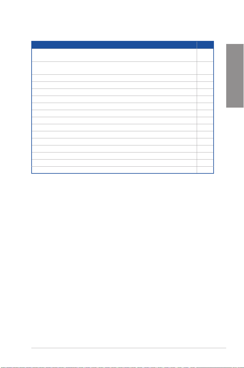
Layout contents
Connectors/Jumpers/Buttons and switches/Slots Page
1. ATX power connectors (24-pin EATXPWR; 8-pin EATX12V_1; 4-pin EATX
12V_2)
2. CPU, CPU optional, and chassis fan connectors; AIO pump connector (4-pin
CPU_FAN, 4-pin CPU_OPT, 4-pin CHA_FAN1-3; 4-pin AIO_PUMP)
3. SPI_TPM connector (14-1 pin SPI_TPM) 1-10
4. AM4 CPU socket 1-4
5. AURA RGB headers (4-pin RGB_HEADER1/2) 1-17
6. DDR4 DIMM slots 1-4
7. Q LEDs 1-8
8. Addressable Gen 2 header (4-pin ADD_GEN2) 1-18
9. USB 3.2 Gen 1 connector (20-1 pin U32G1_12) 1-12
10. M.2 Socket 3 1-16
11. AMD Serial ATA 6 Gb/s connectors (7-pin SATA6G_1-8) 1-11
12. Clear RTC RAM jumper (2-pin CLRTC) 1-9
13. System panel connectors (20-5 pin PANEL) 1-13
14. USB 2.0 connectors (10-1 pin USB78, USB910) 1-12
15. Serial port connector (10-1 pin COM) 1-15
16. Front panel audio connector (10-1 pin AAFP) 1-10
1-15
1-14
Chapter 1
ASUS TUF GAMING X570-PLUS
1-3
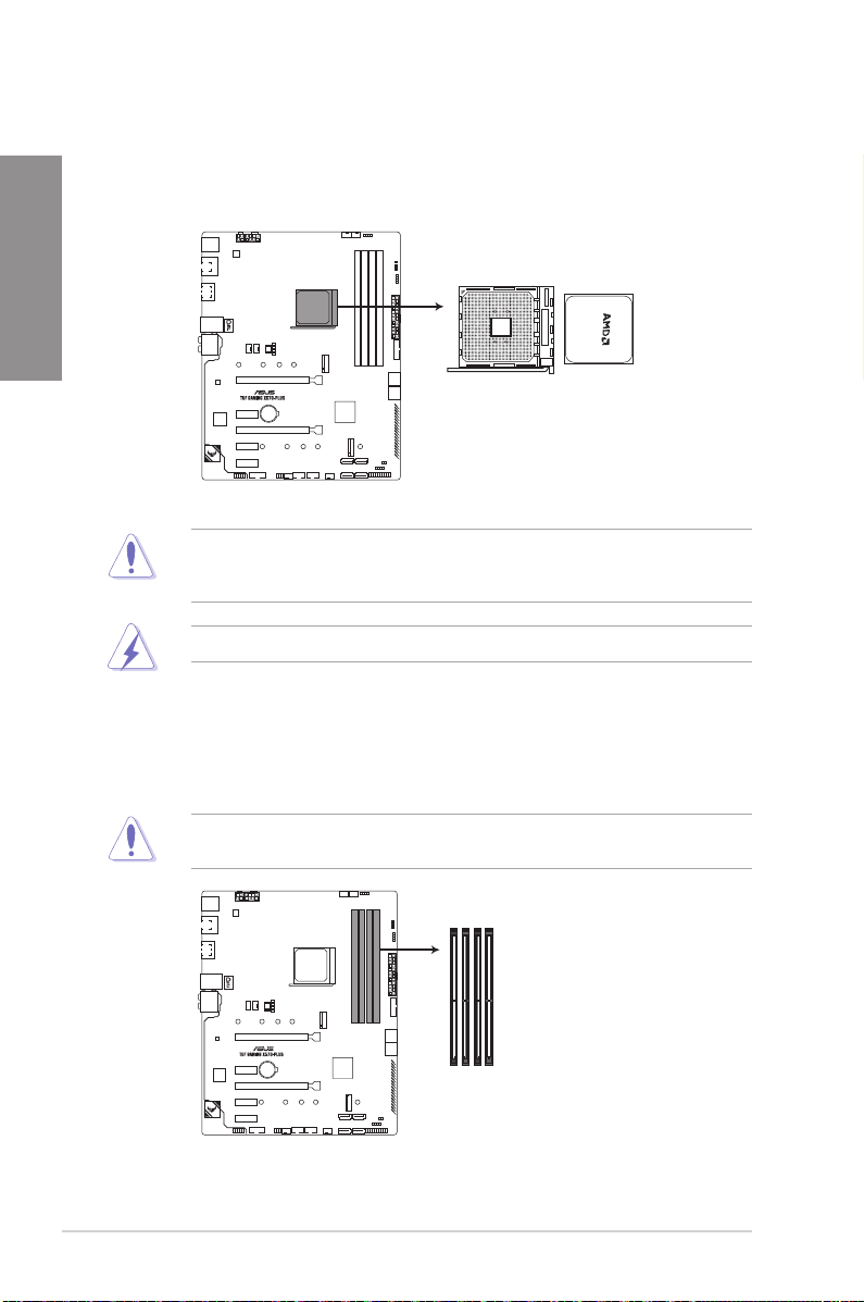
1.1.3 Central Processing Unit (CPU)
The motherboard comes with an AM4 socket designed for AMD Ryzen™ 3
AMD Ryzen™ 2nd and 1st Generation with Radeon™ Vega Graphics processors.
Chapter 1
1.1.4 System memory
The motherboard comes with four Double Data Rate 4 (DDR4) Dual Inline Memory Modules
(DIMM) slots.
rd
and 2nd Generation /
TUF GAMING X570-PLUS CPU socket AM4
The AM4 socket has a different pinout design. Ensure that you use a CPU designed for the
AM4 socket. The CPU ts in only one correct orientation. DO NOT force the CPU into the
socket to prevent bending the connectors on the socket and damaging the CPU!
Ensure that all power cables are unplugged before installing the CPU.
1-4
A DDR4 module is notched differently from a DDR, DDR2, or DDR3 module. DO NOT
install a DDR, DDR2, or DDR3 memory module to the DDR4 slot.
DIMM_B1
DIMM_B2*
DIMM_A1
DIMM_A2*
TUF GAMING X570-PLUS 288-pin DDR4 DIMM sockets
Chapter 1: Product Introduction
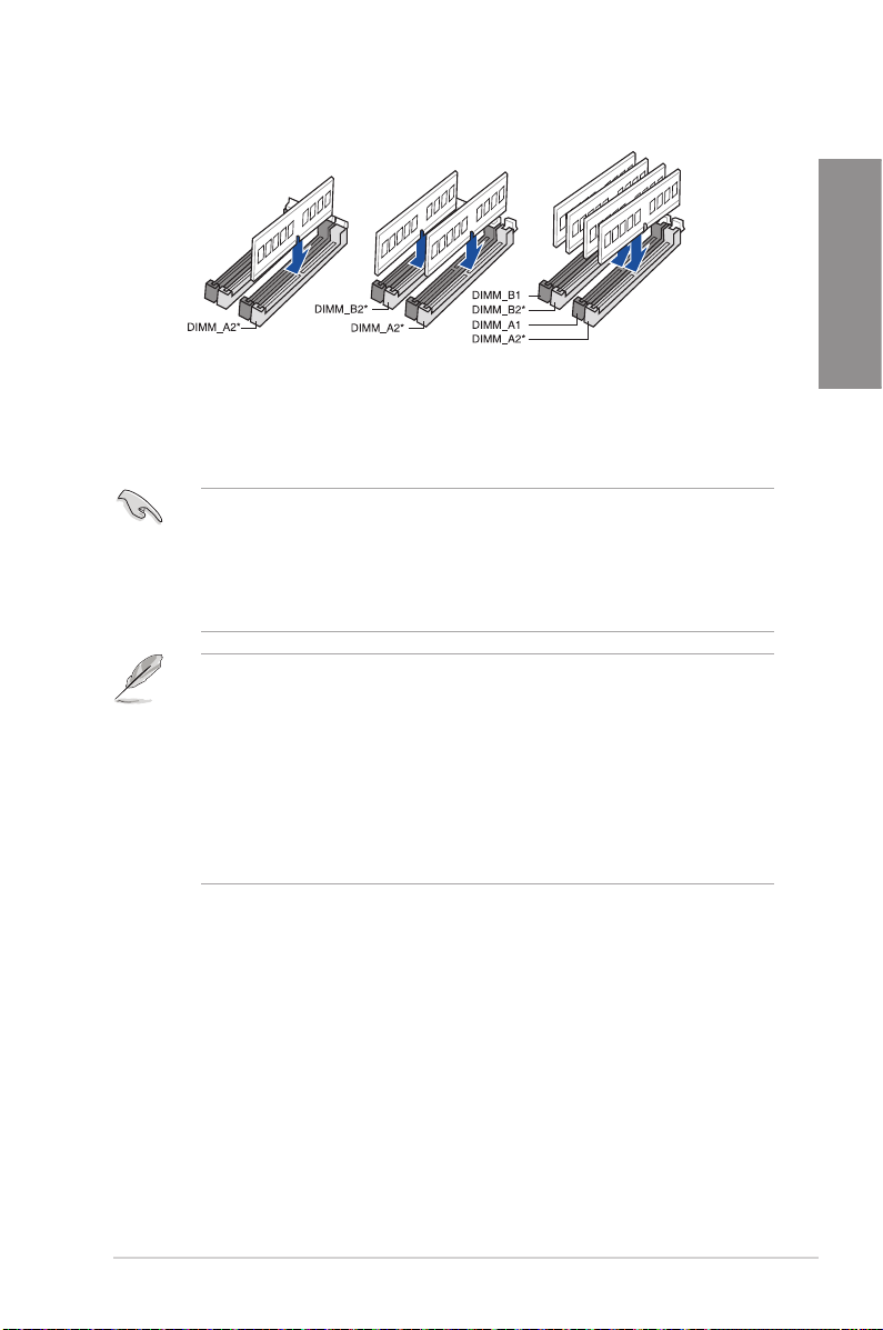
Recommended memory congurations
Memory congurations
You may install 2 GB, 4 GB, 8 GB,16 GB, and s32 GB, unbuffered DDR4 DIMMs into the
DIMM sockets.
• You may install varying memory sizes in Channel A and Channel B. The system
maps the total size of the lower-sized channel for the dual-channel conguration. Any
excess memory from the higher-sized channel is then mapped for single-channel
operation.
• This motherboard does not support DIMMs made up of 512 Mb (64 MB) chips or less
(Memory chip capacity counts in Megabit, 8 Megabit/Mb = 1 Megabyte/MB).
• The default memory operation frequency is dependent on its Serial Presence Detect
(SPD), which is the standard way of accessing information from a memory module.
Under the default state, some memory modules for overclocking may operate at a
lower frequency than the vendor-marked value.
• For system stability, use a more efcient memory cooling system to support a full
memory load (4 DIMMs) or overclocking condition.
• Always install the DIMMS with the same CAS Latency. For an optimum compatibility,
we recommend that you install memory modules of the same version or data code
(D/C) from the same vendor. Check with the vendor to get the correct memory
modules.
Chapter 1
ASUS TUF GAMING X570-PLUS
1-5
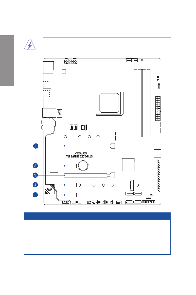
1.1.5 Expansion slots
Chapter 1
Unplug the power cord before adding or removing expansion cards. Failure to do so may
cause you physical injury and damage motherboard components.
PCIEX16_1
PCIEX1_1
PCIEX16_2
PCIEX1_2
5
Slot No. Slot Description
1 PCIe 4.0/3.0 x16_1 slot
2 PCIe 4.0 x1_1 slot
3 PCIe 4.0 x16_2 slot
4 PCIe 4.0 x1_2 slot
5 PCIe 4.0 x1_3 slot
1-6
PCIEX1_3
Chapter 1: Product Introduction
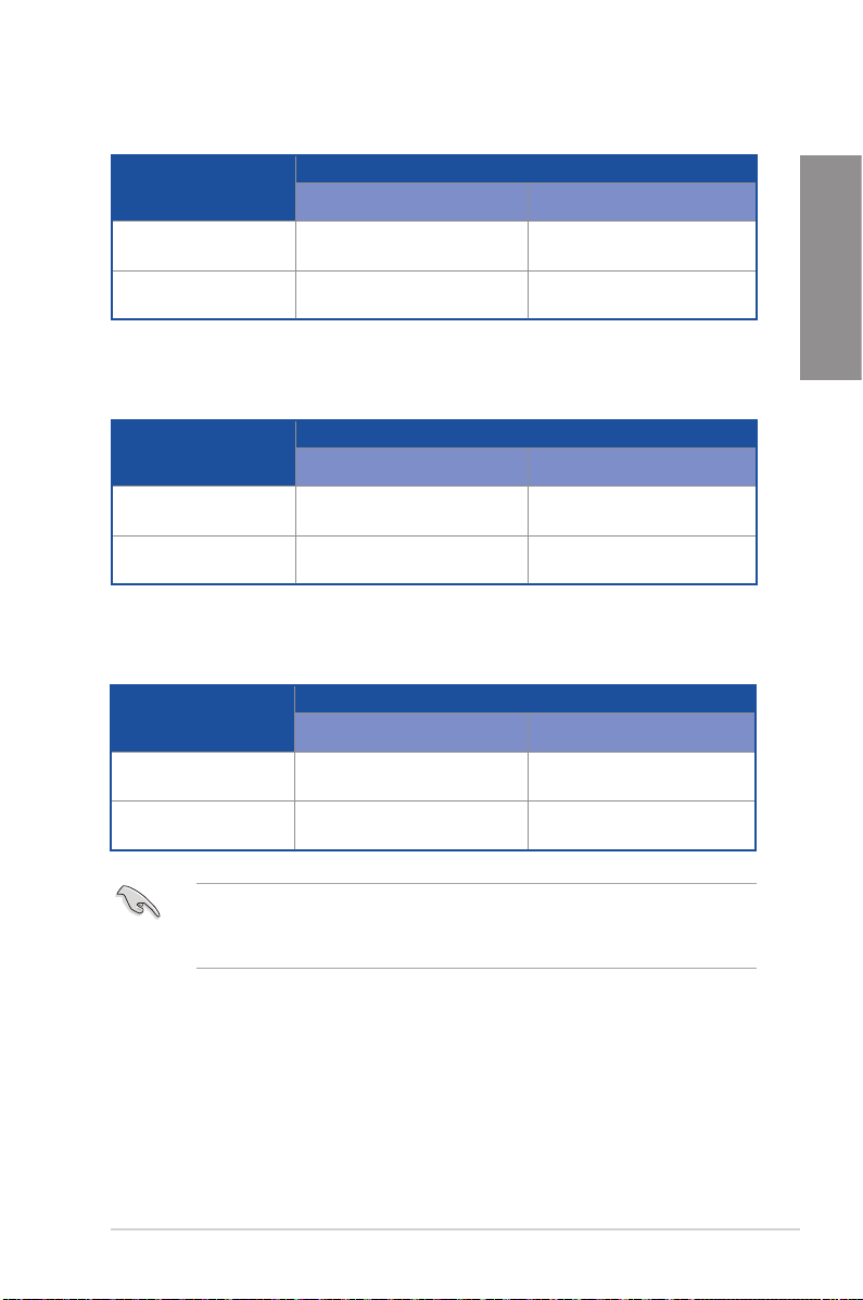
AMD Ryzen™ 3rd Generation Processors
VGA Conguration
Single VGA/PCIe card x16 N/A
Dual VGA/PCIe card x16 x4
PCIe 4.0/3.0 x16_1 PCIe 4.0 x16_2
PCIe operating mode
AMD Ryzen™ 2nd Generation Processors
VGA Conguration
Single VGA/PCIe card x16 N/A
Dual VGA/PCIe card x16 x4
PCIe 3.0 x16_1 PCIe 4.0 x16_2
PCIe operating mode
AMD Ryzen™ 2nd and 1st Generation with Radeon™ Vega Graphics
Processors
VGA Conguration
Single VGA/PCIe card x8 N/A
PCIe 3.0/2.0x16_1 PCIe 4.0 x16_2
PCIe operating mode
Chapter 1
Dual VGA/PCIe card x8 x4
• We recommend that you provide sufcient power when running CrossFireX™ mode.
• Connect chassis fans to the motherboard chassis fan connectors when using multiple
graphics cards for better thermal environment.
ASUS TUF GAMING X570-PLUS
1-7
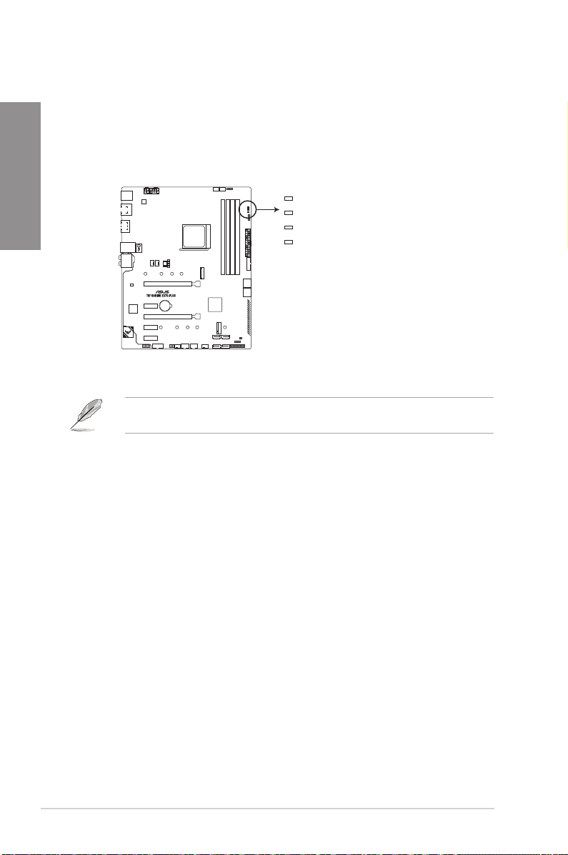
1.1.6 Onboard LEDs
1. Q LEDs (BOOT_LED, VGA_LED, DRAM_LED, CPU_LED)
Chapter 1
Q LEDs check key components (CPU, DRAM, VGA card, and booting devices) in
sequence during motherboard booting process. If an error is found, the corresponding
LED remains lit until the problem is solved. This user-friendly design provides an
intuitive way to locate the root problem within seconds.
BOOT (YELLOW GREEN)
VGA (WHITE)
CPU (RED)
DRAM (YELLOW)
TUF GAMING X570-PLUS
CPU/ DRAM/ BOOT_DEVICE/ VGA LED
The Q LEDs provide the most probable cause of an error code as a starting point for
troubleshooting. The actual cause may vary from case to case.
1-8
Chapter 1: Product Introduction
1.1.7 Jumpers
1. Clear RTC RAM jumper (2-pin CLRTC)
This jumper allows you to clear the CMOS RTC RAM data of the system setup
information such as date, time, and system passwords.
CLRTC
+3V_BAT
GND
PIN 1
TUF GAMING X570-PLUS Clear RTC RAM
To erase the RTC RAM:
1. Turn OFF the computer and unplug the power cord.
2. Use a metal object such as a screwdriver to short the two pins.
3. Plug the power cord and turn ON the computer.
4. Hold down the <Del> key during the boot process and enter BIOS setup to re-enter
data.
Chapter 1
If the steps above do not help, remove the onboard battery and short the two pins again to
clear the CMOS RTC RAM data. After clearing the CMOS, reinstall the battery.
ASUS TUF GAMING X570-PLUS
1-9
1.1.8 Internal connectors
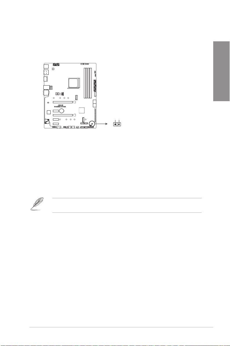
1. Front panel audio connector (10-1 pin AAFP)
Chapter 1
This connector is for a chassis-mounted front panel audio I/O module that supports HD
Audio. Connect one end of the front panel audio I/O module cable to this connector.
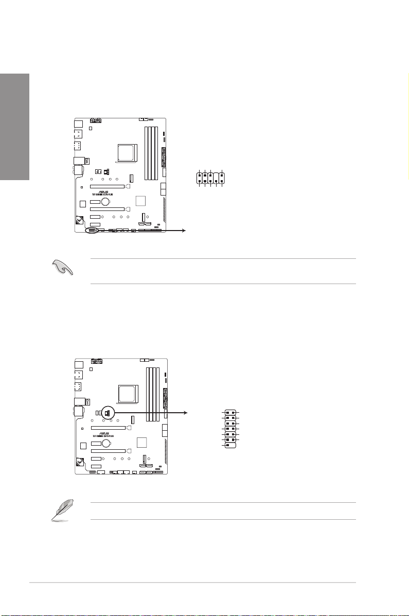
2. SPI_TPM connector (14-1 pin SPI_TPM)
This connector supports a Trusted Platform Module (TPM) system with a Serial
Peripheral Interface (SPI), allowing you to securely store keys, digital certicates,
passwords and data. A TPM system also enhances network security, protects digital
identities, and ensures platform integrity.
AGNDNCSENSE1_RETUR
SENSE2_RETUR
AAFP
PORT1 L
PORT2 L
PORT1 R
PORT2 R
SENSE_SEND
HD-audio-compliant
pin definition
TUF GAMING X570-PLUS Front panel connector
We recommend that you connect a high-denition front panel audio module to this
connector to avail of the motherboard’s high-denition audio capability.
1-10
SPI_TPM
PIN 1
+1.8V TPM
PLTRST#
+18V SPI
SPI CS#
SPI MISO
SPI HOLD#
TUF GAMING X570-PLUS SPI_TPM connector
The SPI_TPM module is purchased separately.
SPI TPM IRQ#
SPI TPM CS#
SPI FLASH WP#
GND
SPI CLK
SPI MOSI
Chapter 1: Product Introduction