

Page 1
RS160-E3/PS4
1U
Page 2

AMD Athlon Opteron AMD
Windows MS-DOS Microsoft
©2006
1)
2)
RS160-E3/PS4
V1 T2320
2006 01
2
Page 3
..........................................................................................................
........................................................................................................
....................................................................
9
10
10
1.1
1.2
1.3
1.4
1.5
1.6 LED
1.6.1
1.6.2
1.6.3
2.1
2.1.1
2.1.2
2.1.2
2.2
2.2.1
2.2.2
2.2.3
2.3
2.3.1
2.3.2
2.3.3
2.3.4
2.4
2.5
2.5.1
2.5.2
2.6
2.7
2.7.1
.........................................................................................
.............................................................................................
.................................................................................................
.................................................................................................
.................................................................................................
................................................................................
................................................................................
............................................................................
................................................................................
.................................................................................................
....................................................................
....................................................................
................................................................................
CPU
.............................................................................
....................................................................................
CPU
CPU
.............................................................................................
................................................................................................
.............................................................................................
...............................................................................................
...............................................................................................
.......................................................................................
/
..........................................................................
..........................................................................
....................................................................................
....................................................................................
....................................................................................
......................................................................
..................................................................................
.............................................................................
1-2
1-3
1-5
1-5
1-6
1-7
1-7
1-7
1-8
2-2
2-2
2-2
2-3
2-4
2-4
2-6
2-6
2-7
2-9
2-7
2-8
2-8
2-9
2-11
2-11
2-13
2-14
2-17
2-17
RS160-E3/PS4
3
Page 4
2.7.2
2.7.3
..................................................................................
..........................................................................................
2-18
2-19
3.1
3.2
3.3
3.4
.................................................................................................
.................................................................................................
.................................................................................
.............................................................................
4.1
4.2
4.3
.........................................................................................
.............................................................................................
.........................................................................
BIOS
5.1 BIOS
5.1.1
5.1.2
5.1.3
5.2 BIOS
5.2.1 BIOS
5.2.2
5.2.3
5.2.4
5.2.5
5.2.6
5.2.7
5.2.8
5.2.9
5.3
5.3.1 System Time [XX:XX:XXXX]
5.3.2 System Date [Day XX/XX/XXXX]
5.3.3 Legacy Diskette A [1.44M, 3.5 in.]
5.3.4 IDE IDE Configuration
5.3.5 IDE
5.3.6
AFUDOS BIOS
CrashFree BIOS 2 BIOS
................................................................................
.....................................................................................
......................................................................................
..........................................................................................
..........................................................................................
......................................................................................
..............................................................................................
..............................................................................
Main Menu
..............................................................................
System Information
..................................................................
....................................................................
......................................................................
..........................................................................
........................................................................
...................................................
.............................
....................................................
.............................................
.............................................
........................................
..............................................
3-2
3-2
3-3
3-4
4-2
4-4
4-9
5-2
5-3
5-6
5-8
5-11
5-12
5-12
5-12
5-13
5-13
5-13
5-13
5-13
5-13
5-14
5-14
5-14
5-14
5-15
5-16
5-17
4
Page 5
5.4 Advanced menu
5.4.1
5.4.2
5.4.3
5.4.4 PCI
5.4.5
5.4.6
5.5
5.6
5.7
5.7.1
5.7.2
5.7
BIOS Exit menu
CPU Configuration
Chipset Configuration
Onboard Devices Configuration
Power Configuration
Hardware Monitor
Server menu
Security menu
Boot menu
Boot Device Priority
Boot Settings Configuration
.............................................................
...........................................
..........................................
..................
PCI PnP
...............................................................
.....................................................................
.................................................
............................................
........................................
............................................................
....................................
.........................
...........................................................
5-19
5-19
5-21
5-23
5-27
5-28
5-31
5-33
5-35
5-38
5-38
5-39
5-41
6.1 RAID
6.1.1 RAID
6.1.2
6.1.3 RAID
6.2 Adaptec SCSI SCSIselect
6.2.1
6.2.2
6.2.3
6.2.4
6.2.5
6.2.6
6.2.7
6.2.8
6.2.9
6.2.10
6.2.11
.....................................................................................
.............................................................................
........................................................................................
SCSI
HostRAID
RAID 0
RAID 1
RAID 0+1
RAID 10
RAID
RAID
..................................................................................
............................................................................
RAID 10
RAID
RAID
7.1 RAID
7.1.1
Red Hat Enterprise ver. 3.0
7.2
.............................................................................
.................................................................................
....................................................................
(TM)
.........................................................................
....................................................................
.....................................................................
..........................................................................
..................................................................
........................................................................
................................................................
..................................................
........................................................
.................................................
..................................
6-2
6-2
6-3
6-3
6-4
6-5
6-5
6-6
6-10
6-13
6-17
6-18
6-20
6-21
6-22
6-23
7-2
7-2
7-5
RS160-E3/PS4
5
Page 6

7.2.1 Windows 2000/2003 Server
Red Hat Enterprise ver. 3.0
7.2.2
7.3
Windows 2000 Server
7.3.1
7.3.2 Red Hat Enterprise ver. 3.0
7.4
7.4.1
7.4.2
7.4.3
7.4.4
7.4.5
.................................................................................
..........................................................................
..............................................................................
..............................................................................
......................................................................................
.................................
..................................
..........................................
................................
...................................................................
..................................................
7-5
7-7
7-9
7-9
7-10
7-11
7-11
7-11
7-12
7-12
7-12
6
Page 7

IC
RS160-E3/PS4
7
Page 8
UPS
IC
8
Page 9
RS160-E3/PS4
Jumper
RS160-E3/PS4
RS160-E3/PS4
BIOS
BIOS BIOS
RS160-E3/PS4
9
Page 10

10
1.
http://tw.asus.com
2.
Page 11

RS160-E3/PS4
Page 12
1.1
RS160-E3/PS4
AR11 1U
PVL-D/1U/SCSI
650W
x 4
SCSI
Front bezel
CPU x 2
AC
x 7 4 x 56 mm; 3 x 28 mm
x 1
RS160-E3/PS4
RS160-E3/PS4 ASWM *
Computer Assoicate
AR11
* ASWM ASUS System Web-based Management
1-2
Page 13
1.2
RS160-E3/PS4 1U PVL-D/1U/SCSI
Intel¤ Socket 604 Xeon
1U
PVL-D/1U/SCSI
Intel E7520 MCH
Intel ICH5R
I/O Intel PXH
Socket 604 Intel Xeon
Xeon Paxille
Intel EM64T
EIST Hyper-Threading
8 240-pin DDR DDRII 400 MHz
registred ECC
16GB
Broadcom
ATI RAGE-XL PCI-based VGA 8MB
1 64-bit/133MHz 3V PCI-X
1 64-bit/133MHz 3V PCI-X *
1 mini-PCI
Adaptec AIC-7902W Ultra320 SCSI
- 2 SCSI HostRAID 0 RAID 1 RAID 0+1
-Zero-Channel RAID
4 x 3.5 SCSI
1 x
2 x USB 2.0
¤
BMC5721 Gigabit PCI-E 1.0a
Location
location LAN1, LAN2
* 2 100 MHz
RS160-E3/PS4
1-3
Page 14
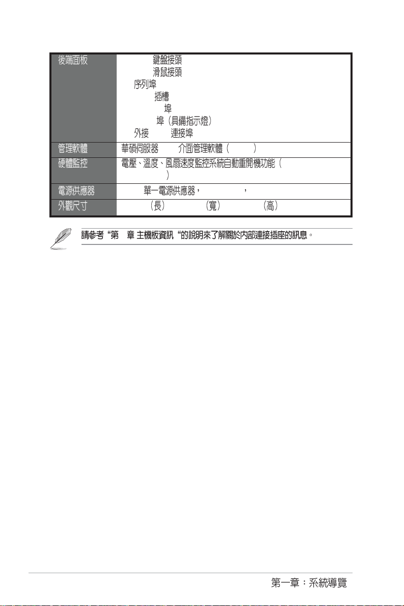
1 x PS/2
1 x PS/2
1 x
1 x VGA
2 x USB 2.0
2 x RJ-45
1 x SCSI
Web ASWM
Automatic System
Restart, ASR
650W 115V~230V 50Hz~60Hz
670mm x 448mm x 43.6 mm
4
1-4
Page 15
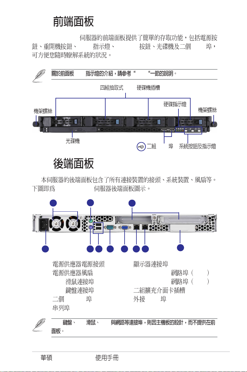
1.3
RS160-E3/PS4
1.4
RS160-E3/PS4
LED Location USB
LED 1.6.1
SCSI
USB
32 10
1 4
1.
2.
3. PS/2
4. PS/2
5. USB2.0
6. COM1
PS/2 PS/2 VGA
RS160-E3/PS4
5 876 9
7.
8. LAN 2 Gibabit RJ45
9. LAN 1 Gigabit RJ45
10.
11. SCSI
11
1-5
Page 16
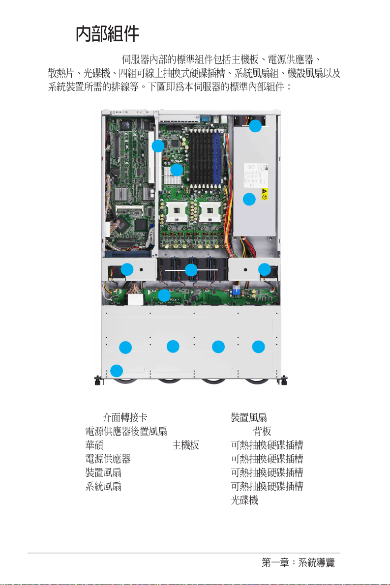
1.5
RS160-E3/PS4 CPU
2
1
3
4
5
8
9
13
1. PCI
2.
3. PVL-D/1U/SCSI
4.
5.
6. x 4
10
6
11
7.
8. SCSI
9. 1
10. 2
11. 3
12. 4
13.
7
12
1-6
Page 17
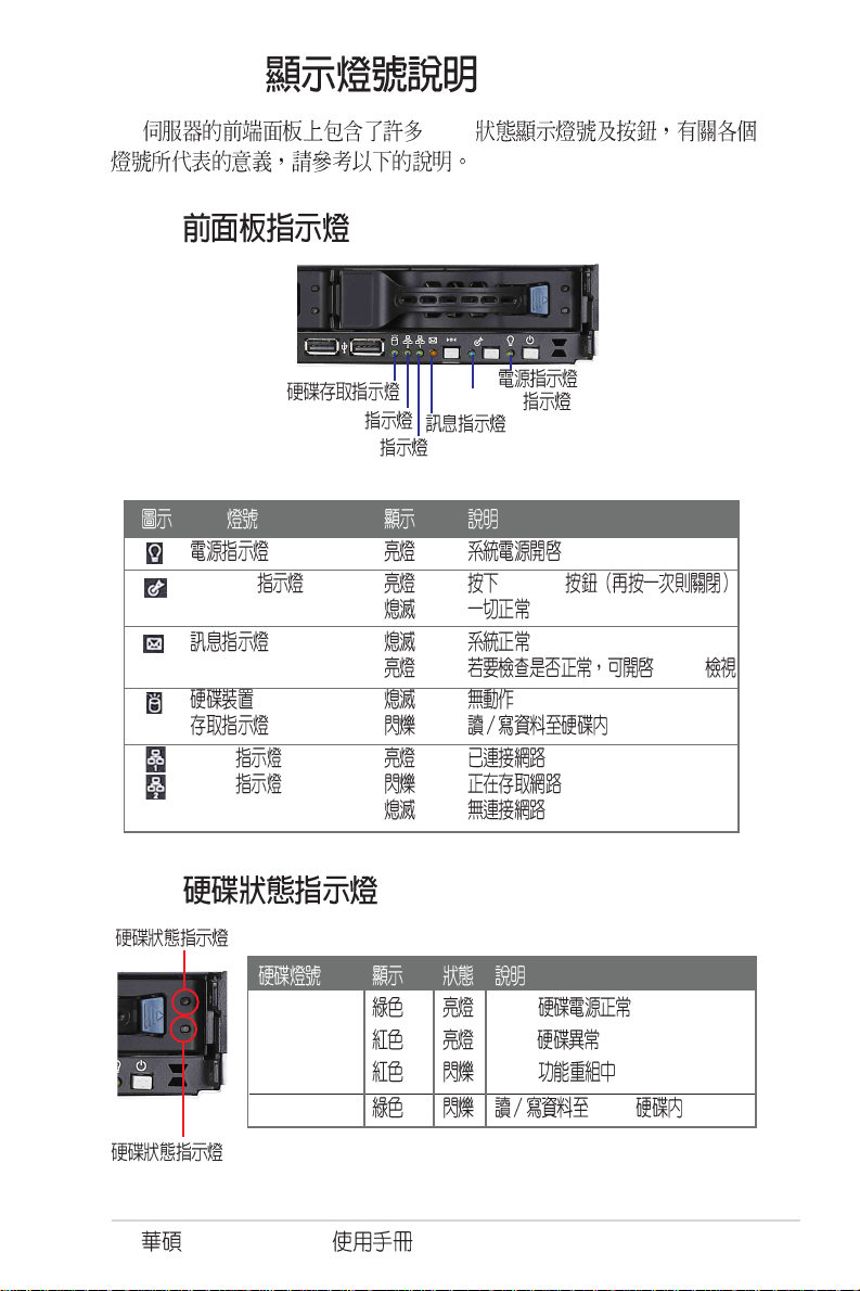
1.6 LED
1.6.1
LED
1.6.2
LAN2
Location
LAN1
LED
Location Location
ASWM
LAN1
LAN2
LED1
LDE1 SCSI
SCSI
RAID
LDE2 SCSI
LED2
RS160-E3/PS4
1-7
Page 18
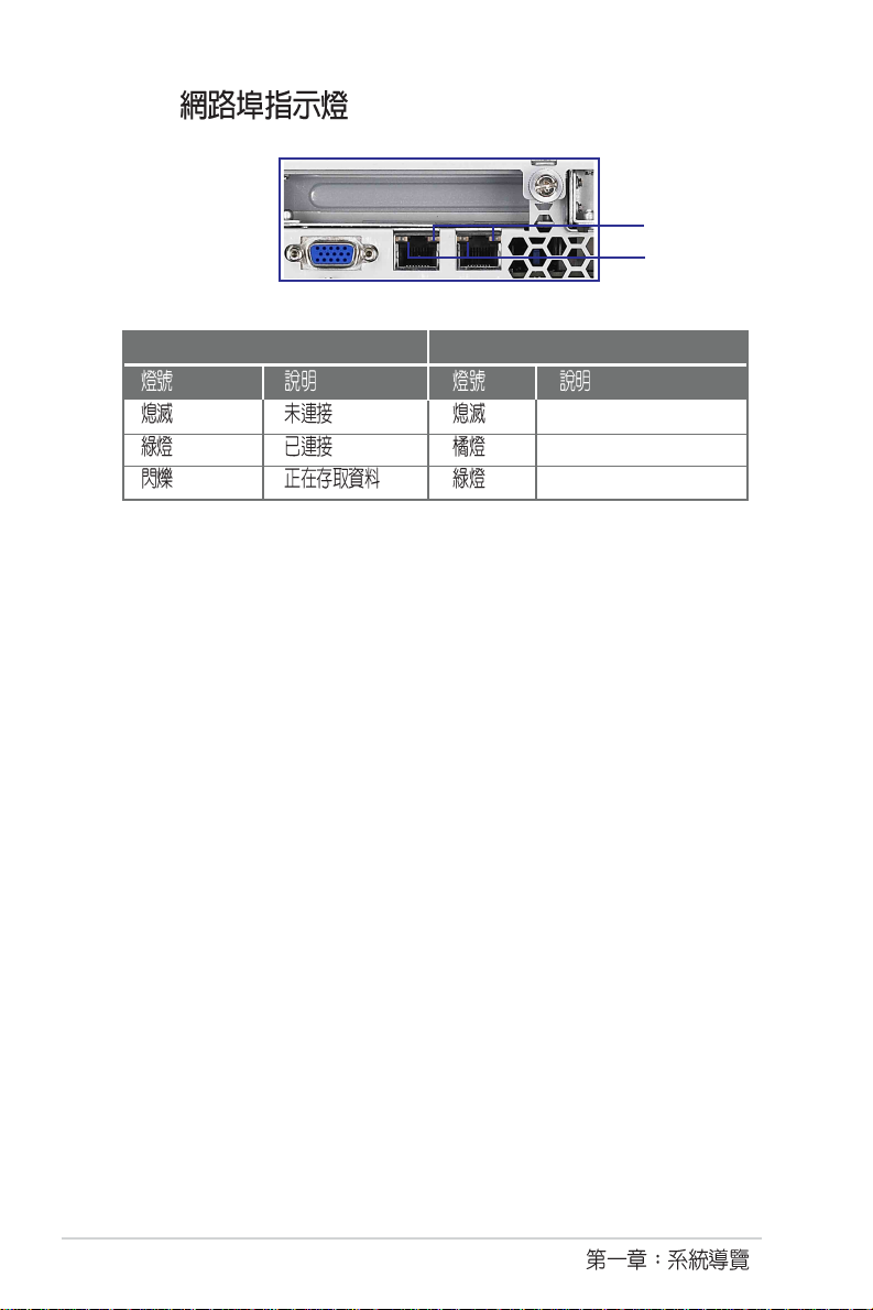
1.6.3
ACT/LINK LED SPEED LED
SPEED LED
ACT/LINK LED
10Mbps
100Mbps
1000Mbps
1-8
Page 19

RS160-E3/PS4
Page 20
2.1
2.1.1
1.
2. SCSI
3.
2-2
4.
2.1.2
1.
Page 21
2.1.2
1.
2.
2.1.3
1.
2.
3.
RS160-E3/PS4
2-3
Page 22
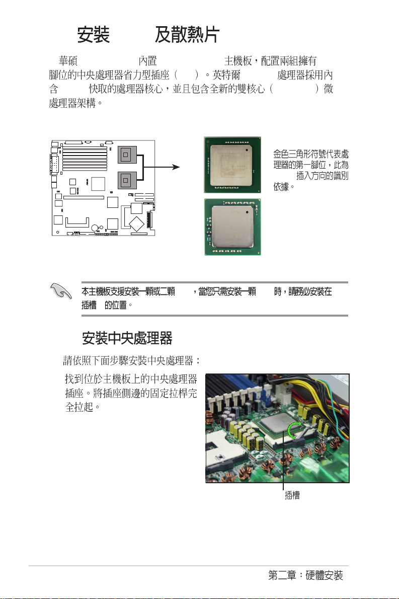
2.2 CPU
®
RS160-E2/CS3 PVL-D/1U/SCSI 604
ZIF XeonTM
L2 2M Dual-Core
Paxville CPU(4MB
L2 Cache)
CPU1
CPU2
PVL-D/1U/SCSI
PVL-D/1U/SCSI CPU Socket 604
1
2.2.1
1.
CPU
Intel Xeon
Irwindale CPU
(2MB L2 Cache)
CPU CPU CPU
CPU 1
2-4
Page 23

2.
3.
4.
RS160-E3/PS4
2-5
Page 24
2.2.2 CPU
1. CPU
CPU
2.
3.
1 2
2.2.3 CPU
1.
CPU
2-6
2.
Page 25
2.3
2.3.1
DDR Double Data Rate DIMM
184-pin registered ECC DDR
DDR DIMM
®
PVL-D/1U/SCSI
PVL-D/1U/SCSI 240-pin DDR2 DIMM sockets
2.3.2
256MB 512MB 1GB 2GB Registered ECC
DDR2 DIMM
1. CL CAS-Latency
2. 2GB 16GB
3. 128MB x16
4.
(1)
(2)
(4)
(6)
(8)
112 Pins128 Pins
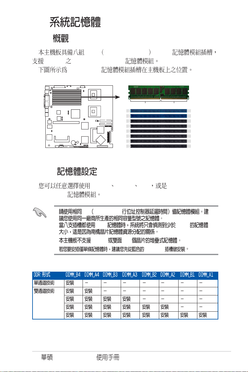
DIMM_B4
DIMM_A4
DIMM_B3
DIMM_A3
DIMM_B2
DIMM_A2
DIMM_B1
DIMM_A1
DIMM_B4
RS160-E3/PS4
2-7
Page 26
2.3.3
1.
2. DDR2
3. DDR2
DDR2 DIMM
DDR2
2.3.4
1.
2. DDR2
2-8
DDR2 DIMM DDR DDR
DDR2 DIMM
DDR2
Page 27
2.4
1.
2.
3.
SCSI
4.
RS160-E3/PS4
2-9
Page 28
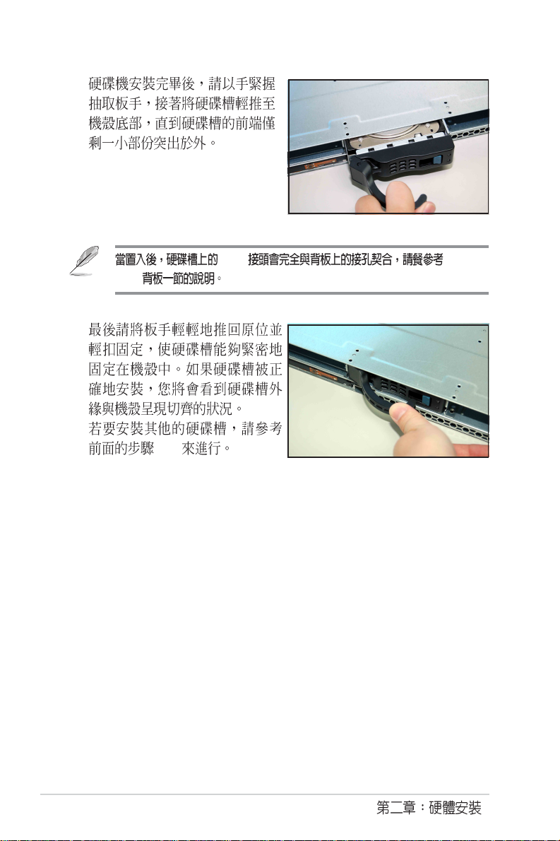
5.
6.
7.
SCSI 2.7.2
SCSI
1~6
2-10
Page 29
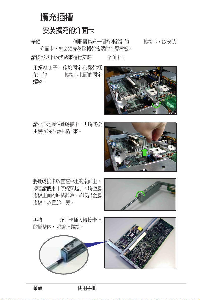
2.6
2.6.1
RS160-E3/PS4 PCI-X
PCI-X
PCI-X
1.
PCI-X
2.
3.
4. PCI-X
RS160-E3/PS4
2-11
Page 30
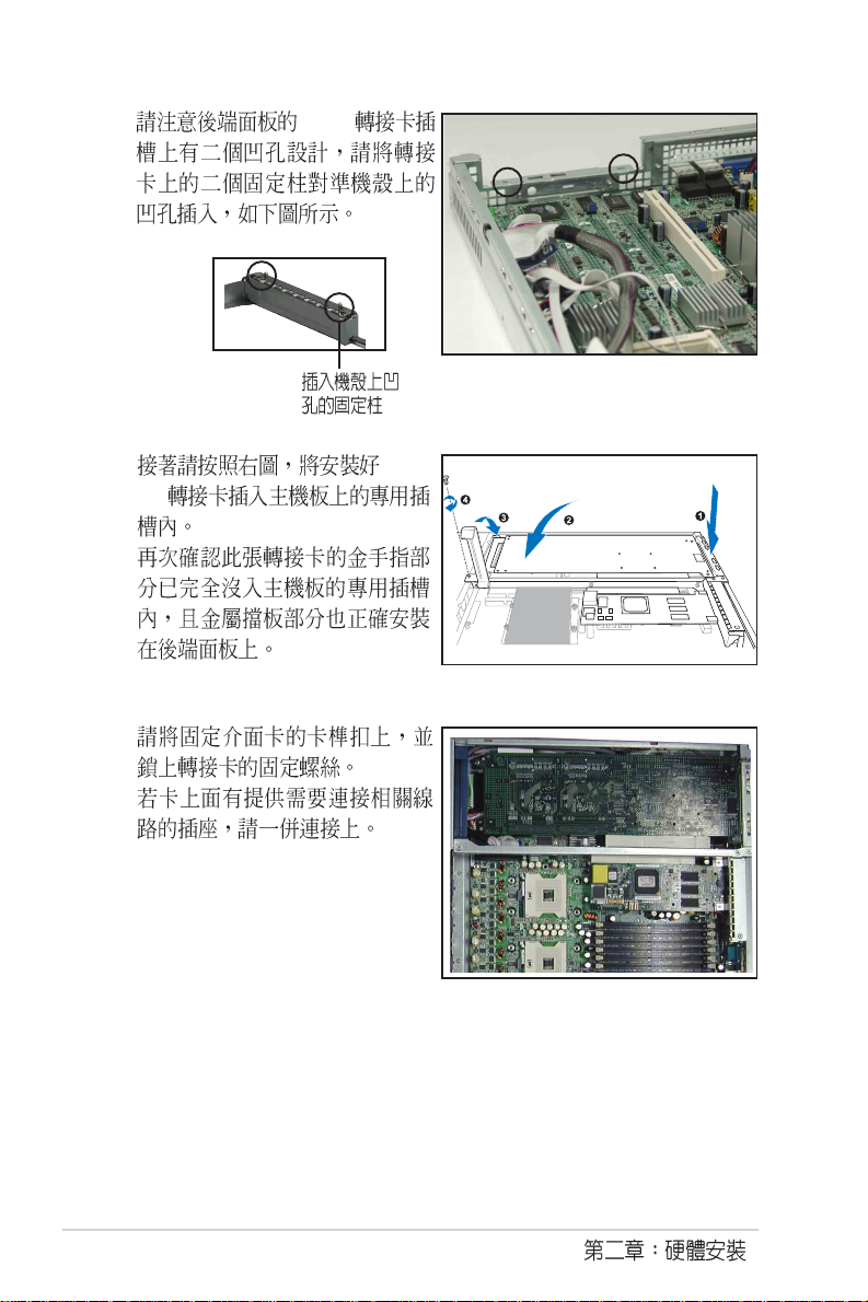
5. PCI
6. PCI X
7.
8.
2-12
9.
Page 31

2.6.3
1. BIOS
BIOS
2. IRQ
3.
IRQ
01
12
2 N/A
3* 11 COM1
4* 12 COM 2
5* 13 PCI
614
7* 15 LPT 1
83 CMOS/
9* 4 PCI
10* 5 PCI
11* 6 PCI
12* 7 PS/2
13 8
14* 9 IDE
15* 10 IDE
*
ICH5R IDE controller PIRQC# - - - - -
INTA# INTB# INTC# INTD# REQ# GNT#
ICH5R SATA controller PIRQC# - - - - ICH5R SMBus controller PIRQB# - - - - ICH5R USB UHCI controller #1 PIRQA# - - - - ICH5R USB UHCI controller #2 PIRQD# - - - - ICH5R USB 2.0 UHCI controller PIRQH# - - - - AIC-7902W SCSI controller PXH2_A_0 PHX2_A_1 - - PXH2_A_0 PXH2_A_0
Zero-Channel RAID sockets PXH2_A_2 - - - PXH2_A_1 PXH2_A_1
ATI Rage XL PIRQB# - - - REQ1H# GNT1#
PCIX Slot1 (64-bit) PXH1_B_0 PXH1_B_1 PXH1_B_2 PXH1_B_3 PXH1_B_0 PXH1_B_0
RS160-E3/PS4
2-13
Page 32

2.6
5
9
6
7
2
10
11
1
1. SMBus BPSMB1 SCSI J1
2. /Locator AUX_PANEL1
3. USB USB34
4. SCSI ( SCSIA1 SCSI U1 )
5. SCSI SCSIB1 SCSI
6. 24-pin SSI ( ATXPWR1 )
7. 5-pin 12C PSUSMB1
8. 8-pin SSI ( ATX12V1 )
9. Locator
10. FRNT_FAN1 SCSI FANIN
11. SCSI FAN1
12. 8 SCSI FAN2~9
13. SCSI FAN10
14. 4-pin
4
14
8
12
PANEL_1
13
3
2-14
Page 33

AMI
8Mb
FWH
KBPWR1
J2
ATXPWR1
SATA1
CPU_FAN2
®
FM_CPU2
SEC_IDE
FLOPPY1
ATI
RAGE XL
VGA
Controller
SCSIA1
BUZZ1
3568
34 1
DDR DIMM_A1 (64/72 bit, 240-pin module)
COM2
Super
I/O
CR2032 3V
Lithium Cell
CMOS Power
PANEL1
FRNT_FAN1
mPGA 604
PS/2
T: Mouse
B: Keyboard
USB1
USB2
COM1
PARALLEL PORT
VGA1
RJ-45
(LAN-1)
RJ-45
(LAN-2)
DDR DIMM_B1 (64/72 bit, 240-pin module)
DDR DIMM_A2 (64/72 bit, 240-pin module)
DDR DIMM_B2 (64/72 bit, 240-pin module)
DDR DIMM_A3 (64/72 bit, 240-pin module)
DDR DIMM_B3 (64/72 bit, 240-pin module)
DDR DIMM_A4 (64/72 bit, 240-pin module)
DDR DIMM_B4 (64/72 bit, 240-pin module)
mPGA 604
33cm (13in)
30.5cm (12in)
PRI_IDE
SCSIB1
FRNT_FAN2
SATA2
ATX12V1
CPU_FAN1
FM_CPU1
Intel
®
ICH5R
Adaptec
®
AIC-7902
Intel
®
E7520
MCH
BMCCONN1
PSUSMB1
BPSMB1
Intel
®
PXH
AUX_PANEL1
HDLED1
SCSI_EN1
USB34
USBPW34
CLRTC1
VGA_EN1
RECPVERY1
LAN1_EN1
LAN2_EN1
Broadcom
BCM5721
Broadcom
BCM5721
SB_PWR1
REAR_FAN1
REAR_FAN2
USBPW12
CPU1
CPU2
PVL-D/1U/SCSI
ZCRSKT1
Intel
®
PXH
PCIX1 (64-bit, 133MHz 3V)
BMC_RACK1
2.6.1
USB 2.0
LED
SMBus SCSI
20-pin
RS160-E3/PS4
IDE SCSI
2-15
Page 34

2.6.2 SCSI
8-pin
SCSI
SCSI 4
SCSI 3
2-16
SCSI
SCSIA1
fan-control
SCSI 2
SCSI 1
SMBus
Page 35

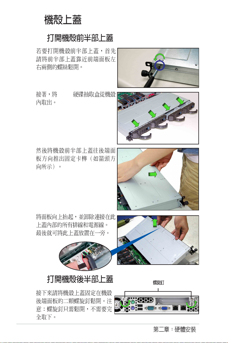
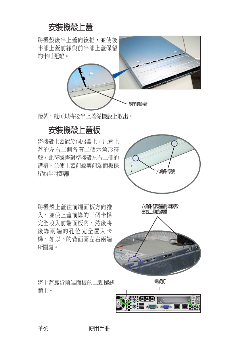
2.7
1. /
2.
3.
2.7.1
1.
2.
3. 1~2
8 2
1.
2.
RS160-E3/PS4
2-17
Page 36

2.7.2
1.
2.
2.7
2-18
3.
Page 37

2.7.3
1.
2.
3.
4.
RS160-E3/PS4
2-19
Page 38

5.
6.
LED
7.
2-20
8.
Page 39

9.
10.
4
RS160-E3/PS4
2-21
Page 40

2-22
Page 41

PS4
RS160-E3/
Page 42

3.1
RS160-E3/PS4
8
80
3.2
1.
2.
3. 2
3-2
Page 43

3.3
1. 1U
2.
3.
4.
1U
5.
6. 1~5
RS160-E3/PS4
3-3
Page 44

3.4
1.
3-4
2.
Page 45

Jumper
Page 46

4.1
PS/2
T: Mouse
B: Keyboard
USB1
USB2
COM1
VGA1
RJ-45
(LAN-1)
RJ-45
(LAN-2)
AMI
8Mb
FWH
Super
I/O
ATI
RAGE XL
VGA
Controller
SB_PWR1
KBPWR1
USBPW12
PARALLEL PORT
VGA_EN1
ATXPWR1
REAR_FAN2
DDR DIMM_B4 (64/72 bit, 240-pin module)
DDR DIMM_A4 (64/72 bit, 240-pin module)
DDR DIMM_B3 (64/72 bit, 240-pin module)
DDR DIMM_A3 (64/72 bit, 240-pin module)
DDR DIMM_B2 (64/72 bit, 240-pin module)
DDR DIMM_A2 (64/72 bit, 240-pin module)
DDR DIMM_B1 (64/72 bit, 240-pin module)
DDR DIMM_A1 (64/72 bit, 240-pin module)
REAR_FAN1
Broadcom
BCM5721
Broadcom
RECPVERY1
BCM5721
PCIX1 (64-bit, 133MHz 3V)
BMC_RACK1
BPSMB1
COM2
LAN1_EN1
LAN2_EN1
FLOPPY1
BMCCONN1
PSUSMB1
CPU_FAN1
®
Intel® E7520
MCH
PVL-D/1U/SCSI
CR2032 3V
Lithium Cell
CMOS Power
AUX_PANEL1
33cm (13in)
BUZZ1
CLRTC1
USB34
ATX12V1
FM_CPU1
USBPW34
Intel
PXH
Intel
PXH
HDLED1
CPU1
CPU2
J2
CPU_FAN2
®
ZCRSKT1
®
SCSI_EN1
PANEL1
mPGA 604
mPGA 604
SEC_IDE
FM_CPU2
PRI_IDE
®
Intel
ICH5R
Adaptec
AIC-7902
34 1
30.5cm (12in)
SATA1
SATA2
FRNT_FAN1
FRNT_FAN2
®
SCSIB1
3568
SCSIA1
4-2
Page 47

/
1. CPU Sockets 4-2
2. DDR2 DIMM sockets 4-2
3. PCI/PCI-X slots 4-2
4. Zero-Channel RAID socket 4-2
5. Mini-PCI socket 4-2
1. Clear RTC RAM (3-pin CLRTC1) 4-4
2. CPU fan pin selection (3-pin FM_CPU1, FM_CPU2) 4-5
3. USB device wake-up (3-pin USBPW12, USBPW34) 4-5
4. Keyboard power (3-pin KBPWR1) 4-6
5. VGA graphics controller (3-pin VGA_EN1) 4-6
6. Gigabit LAN1 controller setting (3-pin LAN1_EN1) 4-7
7. Gigabit LAN2 controller setting (3-pin LAN2_EN1) 4-7
8. SCSI controller setting (3-pin SCSI_EN1) 4-8
9. Force BIOS recovery setting (3-pin RECOVERY1) 4-8
/ /
1. Floppy disk drive connector (34-1 pin FLOPPY1) 4-9
2. IDE connectors (40-1 pin PRI_IDE, SEC_IDE) 4-9
3. Serial ATA connectors (7-pin SATA1, SATA2) 4-10
4. Ultra320 SCSI connectors (two 68-pin SCSIA1, SCSIB1)
(for PVL-D/1U/SCSI) 4-11
5. Hard disk activity LED connector (4-pin HDLED1) 4-12
6. USB port connector (10-1 pin USB34) 4-12
7. Serial port connector (10-1 pin COM2) 4-13
8. CPU and system fan connectors (3-pin CPU_FAN1/2,
REAR_FAN1/2, FRNT_FAN1/2) 4-13
9. BMC connector (6-1 pin BMCCONN1) 4-14
10. Backplane SMBus connector (6-1 pin PSUSMB1) 4-14
11. Power supply SMBus connector (5-pin PSUSMB1) 4-14
12. ATX power connectors (24-pin ATXPWR1, 8-pin ATX12V1) 4-15
14. System panel connector (20-1 pin PANEL1) 4-16
13. Auxiliary panel connector (20-pin AUX_PANEL1) 4-17
RS160-E3/PS4
4-3
Page 48

4.2
1. CMOS CLRTC1
CMOS
CMOS
1
2
3 CLRTC1 [1-2] [2-3]
CMOS [1-2]
4
5
6 <Del> BIOS
BIOS
4-4
®
PVL-D/1U/SCSI
PVL-D/1U/SCSI Clear RTC RAM
21
Normal
(Default)
CLRTC1
32
Clear CMOS
Page 49

2. CPU 3-pin FM_CPU1, FM_CPU2)
CPU 3-
pin 4-pin CPU_FAN1, CPU_FAN2 3-pin
[1-2] 4-pin [2-3]
FM_CPU1
3
®
PVL-D/1U/SCSI
PVL-D/1U/SCSI FM_CPU setting
2
DC mode PWM
(Default)
FM_CPU2
22
1
DC mode PWM
(Default)
2
1
3
3. USB 3-pin USBPW12, USBPW34
+5V USB S1
+5VSB S3 S4
USB
+5V [1-2]
1. USB +5VSB
500mA/+5VSB
2.
+5VSB
3. Windows 2000 Service Pack 4.0 S4
®
PVL-D/1U/SCSI
PVL-D/1U/SCSI USB device wake up
RS160-E3/PS4
USBPW12
2
1
+5V +5VSB
(Default)
USBPW34
2
3
3
2
1
2
+5V+5VSB
(Default)
4-5
Page 50

4. (3-pin KBPWR1)
<Space Bar>
KBPWR [1-2] +5VSB
1A/+5VSB
BIOS
®
PVL-D/1U/SCSI
PVL-D/1U/SCSI Keyboard power setting
(Default)
5. VGA (3-pin VGA_EN1)
VGA [1-2]
KBPWR1
21
+5V +5VSB
32
ATI RAGE-XL PCI
4-6
®
PVL-D/1U/SCSI
PVL-D/1U/SCSI VGA setting
VGA_EN1
1
Enable
(Default)
22
3
Disable
Page 51

6. Gigabit LAN1 3-pin LAN1_EN1)
[1-2] Broadcom Gigabit LAN1
10/100/1000BASE-T
®
PVL-D/1U/SCSI
PVL-D/1U/SCSI LAN1_EN setting
LAN1_EN1
22
1
Enable
(Default)
7. Gigabit LAN2 3-pin LAN2_EN1
[1-2] Broadcom Gigabit LAN2
10/100/1000BASE-T
3
Disable
®
PVL-D/1U/SCSI
PVL-D/1U/SCSI LAN2_EN setting
RS160-E3/PS4
LAN2_EN1
22
1
Enable
(Default)
3
Disable
4-7
Page 52

8. SCSI (3-pin SCSI_EN1)
[1-2] Adaptec AIC-7902W SCSI U320
RAID
®
PVL-D/1U/SCSI
SCSI_EN1
12
PVL-D/SCSI SCSI setting
Enable
(Default)
Disable
9. BIOS (3-pin RECOVERY1)
BIOS
BIOS
1
2 [1-2] [2-3]
3 BIOS xxxxx.ROM
4
5 BIOS
6 [2-3] [1-2]
7
8 <Del> BIOS
23
4-8
®
PVL-D/1U/SCSI
Normal BIOS Recovery
(Default)
PVL-D/1U/SCSI BIOS recovery setting
RECOVERY1
12
23
Page 53

4.3
1. 34-1 pin FLOPPY1
®
PVL-D/1U/SCSI
FLOPPY1
PIN 1
NOTE: Orient the red markings on
the floppy ribbon cable to PIN 1.
PVL-D/1U/SCSI Floppy disk drive connector
2. IDE 40-1 pin PRI_IDE, SEC_IDE
IDE Ultra
DMA 133/100/66 IDE IDE
CD-ROM IDE
Master Slave
Primary Secondary
Slave Ultra DMA 133/100/66 IDE
Master
Ultra DMA 133/100/66 IDE
Slave
1. IDE UltraDMA
2. UltraDMA/100/66 IDE
80 IDE
®
PVL-D/1U/SCSI
PVL-D/1U/SCSI IDE connectors
SEC_IDE
PRI_IDE
NOTE: Orient the red markings
(usually zigzag) on the IDE
ribbon cable to PIN 1.
PIN 1
PIN 1
RS160-E3/PS4
4-9
Page 54

3. Serial ATA 7-pin SATA1, SATA2
Serial ATA Serial ATA Serial ATA
3Gb/s
Serial ATA Intel ICH5R
RAID 0 RAID 1 HostRAID
Standard IDE Serial ATA
/
Serial ATA RAID BIOS Configure SATA As RAID
[Yes] 4.3.5 IDE
®
PVL-D/1U/SCSI
PVL-D/1U/SCSI SATA connectors
GND
GND
GND
RSATA_TXP2
RSATA_TXN2
RSATA_RXN2
RSATA_RXP2
SATA2 SATA1
GND
GND
GND
RSATA_TXP1
RSATA_TXN1
RSATA_RXN1
RSATA_RXP1
4-10
Serial ATA
Windows XP Windows 2000 Serial ATA RAID
Windows XP Service Pack 1 Windows 2000 Service Pack 4
RAID 0 RAID 1 Serial ATA
Standard IDE
SATA 1 SATA 2
Serial ATA
SATA1/SATA2 Master
SATA3/SATA4 Slave
Page 55

4. Ultra320 SCSI 68-pin SCSI1, SCSIB1
Adaptec AIC-7902W SCSI U320 68-pin
Ultra320 SCSI
15 Ultra320
SCSIB1
68-Pin Ultra320/
Ultra2-Wide SCSI Connector
®
PVL-D/1U/SCSI
SCSIA1
68-Pin Ultra320/
Ultra2-Wide SCSI Connector
34 1
3568
PVL-D/SCSI Onboard SCSI connectors
SCSI
SCSI I/O
single-ended (SE) Ultra2 Ultra160 Ultra320 SCSI Ultra320
12 25
320MB/sec SE
SE 1.5m
35
1
6834
SCSI SCSI SCSI
Ultra320 Ultra160 Ultra2 Ultra-Wide
SCSI
68-pin Internal SCSI Cable (Twisted-Pair Ribbon)
®
PVL-D/1U/SCSI
Internal SCSI Devices (up to 15 devices)
68-pin Internal SCSI Cable (Twisted-Pair Ribbon)
PVL-D/SCSI SCSI connection example
RS160-E3/PS4
Internal SCSI Devices (up to 15 devices)
Channel A
68-pin Female
Terminator
Channel B
68-pin Female
Terminator
4-11
Page 56

4. 4-pin HDLED1
®
Add-on Card SCSI/SATA
Add-on Card SCSI/SATA
HDLED1
®
PVL-D/1U/SCSI
SCSI_ACTLED-
SCSI_ACTLED+
PVL-D/1U/SCSI SCSI/SATA card activity LED connector
5. USB 10-1 pin USB34
USB USB 2.0 480Mbps
USB 1.1 12Mbps 40
1
SCSI_ACTLED-
SCSI_ACTLED+
PVL-D/1U/SCSI
Power
USB PortA(-)
USB PortA(+)
GND
NC
GND
USB PortB(+)
1
Power
USB PortB(-)
USB34
PVL-D/1U/SCSI USB connector
4-12
Page 57

6. 10-1-pin COM2
BIOS COM2
COM2 COM2
COM2
®
PVL-D/1U/SCSI
COM2
PIN 1
PVL-D/1U/SCSI Serial port connectors
7. 3-pin FRNT_FAN1/2
REAR_FAN 1/2 FRNT_FAN1/2
350 740 8.88 2.1 4.44
53.28 /+12
+12V GND
Smart Fan
REAR_FAN2
®
PVL-D/1U/SCSI
REAR_FAN1
FRNT_FAN1
FRNT_FAN2
PVL-D/1U/SCSI Fan connectors
CPU_FAN1
CPU_FAN2
CPU_FAN1
GND
FAN Power
FAN Speed
PWM Control
REAR_FAN1
GND
+12V
Rotation
FRNT_FAN1
GND
+12V
Rotation
RS160-E3/PS4
CPU_FAN2
GND
FAN Power
FAN Speed
PWM Control
REAR_FAN2
Rotation
+12V
GND
FRNT_FAN2
GND
+12V
Rotation
4-13
Page 58

9. BMC 16-1 pin BMCCONN1
®
PVL-D/1U/SCSI
PVL-D/1U/SCSI BMC connector
BMCCONN1
+5VSB
+5VSB
BMC SMBCLK
+5VSB
+5VSB
BMC SMBDATA
12CCLK1
PSON#
BMC_RST#
PWROK
PSONEN#
GND
12CDATA1
BMC_SMI#
FP_PWRBTN#
BMC_PRESENT#
10. SMBus 6-1 pin BPSMB1
SMBus System
Management Bus SMBus
®
PVL-D/1U/SCSI
PVL-D/1U/SCSI SMBus connector
BPSMB1
1
FAN_DC
GND
I2C_6_CLK#
I2C_6_DATA#
+5V
11. SMBus 5-pin PSUSMB1
4-14
SMBus
SMBus System Management Bus
®
PVL-D/1U/SCSI
PVL-D/1U/SCSI Power supply SMBus connector
NC
I2C_7_DATA#
GND
I2C_7_CLK#
PSUSMB1
+3.3V Remote Sense
Page 59

12. ATX 24-pin ATXPWR1, 8-pin
ATX12V1
ATX +12V
24 ATXPWR
8-pin +12V
2.0 SSI 12V 450W
8-pin +12V ATX
ATXPWR1 ATX12V1
24-pin Power Connector
8-pin
®
PVL-D/1U/SCSI
+3 Volts
+3 Volts
PVL-D/1U/SCSI ATX power connectors
RS160-E3/PS4
+3 Volts
-12 Volts
Ground
+5 Volts
Ground
PSON#
+5 Volts
Ground
Ground
Ground
Ground
Power OK
-5 Volts
Ground
+5V Standby
+12 Volts
+12 Volts
+5 Volts
+5 Volts
+5 Volts
GND12V
+3 Volts
Ground
For Power Supply
with 24-pin
Power Connector
GND12V
GND12V
GND12V
4-15
Page 60

13. 20-pin PANEL1
®
PVL-D/1U/SCSI
POWERLED+HDLED+
PANEL1
PVL-D/1U/SCSI System panel connector
IDE_LED IDE
IDE
NCHDLED-
POWERLED-
MLED+NMIBTN#
MLED-GND
NCPOWERBTN#
+5VGND
GNDNC
GNDRESETBTN#
SPKROUTGND
4-16
BIOS
Reset
Page 61

14. 20-pin AUX_PANEL1
SMB locator LED
®
PVL-D/1U/SCSI
AUX_PANEL1
PIN1
PVL-D/1U/SCSI Auxiliary panel connector
SMBus
2-pin LAN
I2C_4_CLK#
NC
+5VSB
I2C_4_DATA#LOCATORLED1+
GNDGND
CASEOPEN
+5VSBLOCATORLED1-
LAN1_LINKACTLED+LOCATORBTN#
LAN1_LINKACTLED-GND
LAN2_LINKACTLED-LOCATORLED2-
LAN2_LINKACTLED+LOCATORLED2+
6-pin Locator Locator LED
RS160-E3/PS4
4-17
Page 62

4-18
Page 63

BIOS
BIOS
BIOS
BIOS
Page 64

5.1 BIOS
BIOS
1. ASUS AFUDOS DOS BIOS
2. ASUS CrashFree BIOS 2 BIOS
BIOS
3. ASUS Update Windows BIOS
BIOS
BIOS AFUDOS
BIOS
5-2
BIOS
Page 65

5.1.1 AFUDOS BIOS
AFUDOS DOS BIOS
BIOS AFUDOS BIOS
BIOS
BIOS
1024KB
BIOS
1. AFUDOS afudos.exe
2. DOS
afudos /o[filename]
filename
BIOS
A:\>afudos /oOLDBIOS1.ROM
3. Enter BIOS
A:\>afudos /oOLDBIOS1.ROM
AMI Firmware Update Utility - Version 1.10
Copyright (C) 2002 American Megatrends, Inc. All rights reserved.
Reading flash ..... done
A:\>
BIOS DOS
RS160-E3/PS4
5-3
Page 66

BIOS
AFUDOS BIOS
1. tw.asus.com BIOS
BIOS
2. AFUDOS.EXE BIOS
3. DOS
afudos /i[filename]
filename
BIOS
A:\>afudos /iI8021A00.100
4. AFUDOS BIOS
A:\>afudos /iI8021A00.100 /pbnc
AMI Firmware Update Utility - Version 1.10
Copyright (C) 2002 American Megatrends, Inc. All rights reserved.
Reading file ....... done
Erasing flash ...... done
Advance Check ......
Erasing flash ...... done
Writing flash ...... 0x0008CC000 (9%)
BIOS
5-4
BIOS
Page 67

5. BIOS DOS
A:\>afudos /iI8021A00.100 /pbnc
AMI Firmware Update Utility - Version 1.10
Copyright (C) 2002 American Megatrends, Inc. All rights reserved.
WARNING!! Do not turn off power during flash BIOS
Reading file ....... done
Erasing flash ...... done
Advance Check ......
Erasing flash ...... done
Writing flash ...... done
Verifying flash .... done
Please restart your computer
A:\>
RS160-E3/PS4
5-5
Page 68

5.1.2 CrashFree BIOS 2 BIOS
CrashFree BIOS 2 BIOS
BIOS BIOS
1. BIOS
BIOS
2. BIOS I8021A00.100
BIOS
BIOS
1.
2. BIOS
3.
BIOS
Bad BIOS checksum. Starting BIOS recovery...
Checking for floppy...
5-6
BIOS
Bad BIOS checksum. Starting BIOS recovery...
Checking for floppy...
Floppy found!
Reading file “K8NDRE.ROM”. Completed.
Start flashing...
BIOS
4.
BIOS
Page 69

BIOS
BIOS
1.
2.
3.
BIOS
Bad BIOS checksum. Starting BIOS recovery...
Checking for floppy...
Bad BIOS checksum. Starting BIOS recovery...
Checking for floppy...
Floppy not found!
Checking for CD-ROM...
CD-ROM found!
Reading file “I8021A00.100”. Completed.
Start flashing...
4. BIOS
RS160-E3/PS4
BIOS
BIOS BIOS
http://tw.asus.com BIOS
5-7
Page 70

5.1.3
Windows
BIOS
1. BIOS
2. BIOS
3. BIOS BIOS
4. BIOS
5. BIOS
ISP
1.
2. VX.XX.XX
3.
5-8
BIOS
BIOS
Page 71

BIOS
BIOS
1. ASUS ASUSUpdate ASUSUpdate
2. Update BIOS
from the Internet
Next
3. FTP
Auto Select
Next
RS160-E3/PS4
5-9
Page 72

4. BIOS
Next
5.
BIOS
BIOS
BIOS BIOS
BIOS BIOS
1. ASUS
ASUSUpdate ASUSUpdate
2. Update BIOS
from a file Next
3. BIOS
4.
BIOS
5-10
BIOS
Page 73

5.2 BIOS
BIOS Basic Input and Output System
BIOS
BIOS
BIOS
RUN SETUP
BIOS
BIOS
Flash ROM BIOS Flash
ROM
BIOS BIOS
BIOS
CMOS RAM
BIOS
POST Power-On Self Test
DELETE DELETE
RESET Ctrl +
Alt + Delete
BIOS
1. BIOS
BIOS
BIOS Load Setup Defaults
2. BIOS
3. tw.asus.com BIOS BIOS
RS160-E3/PS4
5-11
Page 74

5.2.1 BIOS
Main Advanced Server Security Boot Exit
System Date [Thu 09/22/2005]
System Time [11:10:19]
Legacy Diskette A [1.44M, 3.5 in]
IDE Configuration
Primary IDE Master :[ST32122A]
Primary IDE Slave : [ASUS CD-S520A]
Secondary IDE Master :[Not Detected]
Secondary IDE Slave :[Not Detected]
Third IDE Master : [Not Detected]
Fourth IDE Master : [Not Detected]
System Information
v00.00 (C) Copyright 1985-2004, American Megatrends, Inc.
BIOS SETUP UTILITY
5.2.2
BIOS
Main
Advanced
Server
Security
Boot
Exit BIOS
Use [ENTER], [TAB]
or [SHIFT-TAB] to
select a field.
Use [+] or [-] to
configure system time.
Select Screen
Select Item
+- Change Option
F1 General Help
F10 Save and Exit
ESC Exit
5-12
5.2.3
BIOS
Page 75

5.2.4
Main
Advanced Power Boot Exit
5.2.5
5.2.6
5.2.7
System Date [Thu 09/22/2005]
System Time [11:10:19]
Legacy Diskette A [1.44M, 3.5 in]
IDE Configuration
Primary IDE Master :[ST32122A]
Primary IDE Slave :[ASUS CD-S520A]
Secondary IDE Master :[Not Detected]
Secondary IDE Slave :[Not Detected]
Third IDE Master :[Not Detected]
Fourth IDE Master :[Not Detected]
System Information
Enter
Advanced PCI/PnP Settings
WARNING: Setting wrong values in
below sections may cause system to
malfunction.
Plug And Play O/S [No]
PCI Latency Timer [64]
Allocate IRQ to PCI VGA [Yes]
Palette Snooping [Disabled]
PCI IDE BusMaster [Enabled]
Use [ENTER],
[TAB] or [SHIFTTAB] to select a
field.
Use [+] or [-] to
configure the
System time.
5.2.8
5.2.9
RS160-E3/PS4
Enter
PageUp PageDown
5-13
Page 76

5.3 Main Menu
BIOS
5.2.1 BIOS
Main Advanced Server Security Boot Exit
System Date [Thu 09/22/2005]
System Time [11:10:19]
Legacy Diskette A [Disabled]
IDE Configuration
Primary IDE Master :[ST32122A]
Primary IDE Slave : [ASUS CD-S520A]
Secondary IDE Master :[Not Detected]
Secondary IDE Slave :[Not Detected]
Third IDE Master : [Not Detected]
Fourth IDE Master : [Not Detected]
System Information
v00.00 (C) Copyright 1985-2004, American Megatrends, Inc.
BIOS SETUP UTILITY
Use [ENTER], [TAB]
or [SHIFT-TAB] to
select a field.
Use [+] or [-] to
configure system time.
Select Screen
Select Item
+- Change Option
F1 General Help
F10 Save and Exit
ESC Exit
5.3.2 System Date [Day XX/XX/XXXX]
1 12 1 31 2099 Tab Tab +
Shift
5.3.1 System Time [XX:XX:XXXX]
00 23 00 59 00 59 Tab
Tab + Shift
5.3.3 Floppy A [Disabled]
[Disabled] [360K, 5.25
in.] [1.2M, 5.25 in.] [720K, 3.5 in.] [1.44M, 3.5 in.] [2.88M, 3.5 in.]
5-14
BIOS
Page 77

5.3.4 IDE IDE Configuration
IDE
Enter
Main
IDE Configuration
Onboard IDE Operate Mode [Enhanced Mode]
Enhanced Mode Support On [S-ATA]
IDE Detect Time Out (Sec) [35]
v00.00 (C) Copyright 1985-2004, American Megatrends, Inc.
Onboard IDE Operate Mode [Enhanced Mode]
[Compatible Mode ] [Enhanced Mode]
Onboard IDE Operate Mode [Enhanced Mode] Enhanced Mode
Support On Configure S-ATA as RAID
BIOS SETUP UTILITY
Set [Compatible Mode
] when OS (i.e. WIN
ME, 98, or MS DOS)
is used.
Set [enhanced Mode]
when native OS (i.e.
WIN2000, WIN XP) is
used.
Select Screen
Select Item
+- Change Option
F1 General Help
F10 Save and Exit
ESC Exit
Windows 2000/XP
[Enhanced Mode] [Disabled]
Enhanced Mode Support On [S-ATA]
Serial ATA Parallel ATA
[P-ATA+S-ATA] [S-ATA] [P-ATA]
Enhanced Moed Support On [S-ATA] [P-ATA+
S-ATA]
IDE Detect Time Out [35]
ATA/ATAPI [0]
[5] [10] [15] [20] [25] [30] [35]
RS160-E3/PS4
5-15
Page 78

5.3.5 IDE (Primary/Secondary IDE Master/
Slave, Third, and Fourth IDE Master)
BIOS IDE
IDE Enter
Main
Primary IDE Master
Device : Hard Disk
Vendor : ST32122A
Size : 2.1GB
LBA Mode : Supported
Block Mode : 16 Sectors
PIO Mode : Supported
Async DMA : MultiWord DMA-2
Ultra DMA : Ultra DMA-5
SMART Monitoring: Supported
Type [Auto]
LBA/Large Mode [Auto]
Block(Multi-sector Transfer) [Auto]
PIO Mode [Auto]
DMA Mode [Auto]
S.M.A.R.T. [Auto]
32Bit Data Transfer [Disabled]
v00.00 (C) Copyright 1985-2004, American Megatrends, Inc.
BIOS SETUP UTILITY
Select the type or
device connected to
the system.
Select Screen
Select Item
+- Change Option
F1 General Help
F10 Save and Exit
ESC Exit
Device Vendor Size LBA Mode Block
Mode PIO Mode Async DMA Ultra DMA S.M.A.R.T. monitoring
BIOS N/A
Type [Auto]
IDE Auto
IDE CDROM IDE
ARMD ATAPI IDE
ZIP LS-120 MO [Not
Installed] [Auto] [CDROM] [ARMD]
LBA/Large Mode [Auto]
LBA [Auto]
LBA LBA
[Disabled] [Auto]
Block (Multi-sector Transfer) [Auto]
[Disabled]
[Disabled] [Auto]
5-16
[Auto]
BIOS
Page 79

PIO Mode [Auto]
PIO [Auto] [0] [1] [2] [3] [4]
SMART Monitoring [Auto]
Smart Monitoring, Analysis, and
Reporting Technology [Auto] [Disabled] [Enabled]
32Bit Data Transfer [Enabled]
32 [Disabled] [Enabled]
5.3.6 System Information
BIOS
Main
System Information
Model Name ASUSPVL-D/1U/SCSI
Model ID 8021AD
ASUS BIOS
Version 1001
Date 09/20/2005
Processor
System Memory
v00.00 (C) Copyright 1985-2004, American Megatrends, Inc.
BIOS SETUP UTILITY
Select Screen
Select Item
+- Change Option
F1 General Help
F10 Save and Exit
ESC Exit
Model Name
Model ID
ASUS BIOS
RS160-E3/PS4
BIOS
5-17
Page 80

Processor
Main
Processor Information
***CPU1:
Brand Genuine Intel(R) CPU 2.80GHz
ID/uCode 0F34h/07h
Ratio Actual 14 Max 14
Cache L1/16KB L2/2048KB L3/0KB
***CPU1:
Brand Genuine Intel(R) CPU 2.80GHz
ID/uCode 0F34h/07h
Ratio Actual 14 Max 14
Cache L1/16KB L2/2048KB L3/0KB
v00.00 (C) Copyright 1985-2004, American Megatrends, Inc.
BIOS SETUP UTILITY
System Memory
Main
System Memory Information
Type DDR2 400
Total Memory 512MB
DIMM01 512MB
DIMM02 None
DIMM03 None
DIMM04 None
DIMM05 None
DIMM06 None
DIMM07 None
DIMM08 None
v00.00 (C) Copyright 1985-2004, American Megatrends, Inc.
BIOS SETUP UTILITY
Select Screen
Select Item
+- Change Option
F1 General Help
F10 Save and Exit
ESC Exit
Select Screen
Select Item
+- Change Option
F1 General Help
F10 Save and Exit
ESC Exit
5-18
BIOS
Page 81

5.4 Advanced menu
Advanced
Advanced Settings
CPU Configuration
Chipset Configuration
Onboard Device Configuration
PCI/PnP Configuration
Power Configuration
Hardware Monitor
v00.00 (C) Copyright 1985-2004, American Megatrends, Inc.
BIOS SETUP UTILITY
Configure CPU.
5.4.1 CPU Configuration
<Enter>
CPU Configuration
MPS Table Version [1.4]
Single Logical Processor Mode: [Disabled]
Hyper Threading Technology [Enabled]
Max CPUID Value Limit [Disabled]
Execute Disable Function [Disabled]
Enhanced C1 Control [Auto]
CPU Internal Thermal Control [Auto]
Intel(R) SpeedStep(tm) Tech. [Aueomatic]
Select MPS Pevision.
Select Screen
Select Item
+- Change Option
F1 General Help
F10 Save and Exit
ESC Exit
Select Screen
Select Item
+- Change Option
F1 General Help
Select Screen
F10 Save and Exit
Select Item
ESC Exit
+- Change Option
F1 General Help
F10 Save and Exit
ESC Exit
MPS Table Version [1.4]
RS160-E3/PS4
MPS [1.1] [1.4]
5-19
Page 82

Single Logical Processor Mode [Disabled ]
dual-core
[Disabled] [Enabled]
Hyper Threading Technology [Enabled]
Hyper Threading
Hyper-Threading Intel Pentium 4
[Disabled] [Enabled]
Max CPUID Value Limit [Disabled]
CPUID
[Enabled] [Disabled] [Enabled]
Execute Disabled Function [ ]
[Disabled] BIOS XD
(0) [Disabled] [Enabled]
Enhanced C1 Control [Auto]
[Auto] BIOS CPU C1E
C1E CPU CPU idle
[Auto] [Disabled]
CPU Internal Thermal Control [Auto]
[Auto] BIOS
[Auto] [Disabled]
Intel SpeedStep EIST Intel
Intel(R) Speedstep(tm) Tech [Automatic]
[Automatic] BIOS Speedstep
Intel
EIST [Disabled]
[Automatic] [Disabled]
A EIST
EIST BIOS
5-20
BIOS
Page 83

5.4.2 Chipset Configuration
Enter
Advanced
Advanced Chipset Settings
WARNING: Setting worng values in below sections
may cause system to malfunction.
NorthBridge Configuration
Onboard LAN Boot ROM [Enabled]
Onboard SCSI Boot ROM [Enabled]
v00.00 (C) Copyright 1985-2004, American Megatrends, Inc.
BIOS SETUP UTILITY
OnBoard LAN Boot ROM [Enabled]
option ROM [Disabled] [Enabled]
OnBoard SCSI Boot ROM [Enabled]
SCSI
option ROM [Disabled] [Enabled]
Options for NB.
Select Screen
Select Item
+- Change Option
F1 General Help
F10 Save and Exit
ESC Exit
RS160-E3/PS4
5-21
Page 84

Advanced
NorthBridge Configuration
DIMM SPEED: DDR2 400
Memory Remap Feature [Enabled]
Memory Mirroring/Sparing [Disabled]
v00.00 (C) Copyright 1985-2004, American Megatrends, Inc.
BIOS SETUP UTILITY
DIMM SPEED
DIMM
Memory Remap Feature [Enabled]
[Enabled]
Memory Mirroring/Sparing [Disabled]
[Disabled] [Mirroring] [Sparing]
ENABLED: Allow
remapping of
overlapped PCI
memory above the
total physical
memory.
DISABLED: Do not
allow remapping of
memory.
Select Screen
Select Item
+- Change Option
F1 General Help
F10 Save and Exit
ESC Exit
[Disabled]
Mirroring Sparing
5-22
BIOS
Page 85

5.4.3
Advanced
NorthBridge Configuration
USB Configuration
Super IO Configuration
v00.00 (C) Copyright 1985-2004, American Megatrends, Inc.
BIOS SETUP UTILITY
USB
USB
Enter
Advanced
USB Configuration
Module Version - 2.23.2-5.3
USB Device Enable:
None
USB Funtion [4 USB Ports]
Legacy USB Support [Auto]
USB 2.0 Controller [Enabled]
USB 2.0 Controller Mode [HiSpeed]
USB Mass Storage Device Configuration
v00.00 (C) Copyright 1985-2004, American Megatrends, Inc.
BIOS SETUP UTILITY
Configure the USB
support.
Select Screen
Select Item
+- Change Option
F1 General Help
F10 Save and Exit
ESC Exit
Select Screen
Select Item
+- Change Option
F1 General Help
F10 Save and Exit
ESC Exit
Module Version USB Device Enabled
USB USB Devices None
USB Functions [4 USB Ports]
USB USB
[Disabled] [2 USB Ports] [4 USB Ports]
RS160-E3/PS4
5-23
Page 86

Legacy USB Support [Auto]
USB [Auto]
USB USB
[Disabled]
USB USB
[Disabled] [Enabled] [Auto]
USB 2.0 Controller [Disabled]
USB 2.0 [Enabled]
[Disabled]
USB 2.0 Controller Mode [HiSpeed]
USB 2.0 HiSpeed 480 Mbps
Full Speed 12 Mbps [HiSpeed] [Full Speed]
USB Mass Storage Device Configuration
USB Mass Storage Reset Delay [20 Sec]
Number of seconds POST
waits for the USB mass
device after start
unit command.
Select Screen
Select Item
+- Change Option
F1 General Help
F10 Save and Exit
ESC Exit
USB Mass Storage Reset Delay [20 Sec]
POST USB
USB mass storage device
detected [10 Sec ] [20 Sec] [30 Sec] [40 Sec]
5-24
BIOS
Page 87

Super IO
Advanced
Configure Win83627THF Super IO Chipset
Serial Port1 Address [3F8/IRQ4]
Serial Port2 Address [2F8/IRQ3]
Serial Port2 Mode [Normal]
v00.00 (C) Copyright 1985-2004, American Megatrends, Inc.
BIOS SETUP UTILITY
Serial Port1 Address [3F8/IRQ4]
COM 1 [Disabled] [3F8/IRQ4]
[3E8/IRQ4]
Serial Port2 Address [2F8/IRQ3]
COM 2 [Disabled] [2F8/IRQ3]
[2E8/IRQ3]
Serial Port2 Mode [Normal]
COM2 [Normal] [IrDA]
[ASK IR]
Allows BIOS to select
Serial Port1 Base
Addresses.
Select Screen
Select Item
+- Change Option
F1 General Help
F10 Save and Exit
ESC Exit
Serial Port2 Mode [IrDA] [Ask IR]
IR I/O Pin Select [SINB/SOUTHB]
BIOS Serial Port2 IR Mode Pin
[SINB/SOUTHB] [IRRY/IRTX]
IR Duplex Mode [Half Duplex]
BIOS Serial Port2 IR Mode full half duplex
[Full Duplex] [Half Duplex]
RS160-E3/PS4
5-25
Page 88

Parallel Port Address [378] [278] [3BC]
Parallel Port Mode [Normal]
Parallel Port [Normal] [Bi-Direction]
[EPP] [EPC]
Parallel Port IRQ [IRQ7]
Parallel Port IRQ [IRQ5] [IRQ7]
5-26
BIOS
Page 89

5.4.4 PCI PCI PnP
PCI/PnP PCI/PnP
IRQ DMA ISA
ISA
Advanced
PCI/PnP Configuration
Plug and Play OS [No]
Palette Snooping [Disabled]
IRQ-3 assigned to [PCI Device]
IRQ-4 assigned to [PCI Device]
IRQ-5 assigned to [PCI Device]
IRQ-7 assigned to [PCI Device]
IRQ-9 assigned to [PCI Device]
IRQ-10 assigned to [PCI Device]
IRQ-11 assigned to [PCI Device]
IRQ-14 assigned to [PCI Device]
IRQ-15 assigned to [PCI Device]
v00.00 (C) Copyright 1985-2004, American Megatrends, Inc.
BIOS SETUP UTILITY
Plug and Play O/S [No]
[No] BIOS
[Yes] [No] [Yes]
Palette Snooping [Disabled]
MPEG
[Enabled]
VGA [Disabled]
[Disabled] [Enabled]
IRQ-XX assigned to [PCI Device]
NO: Lets the BIOS
configue all the
devices in the system.
YES: Lets the
operating system
configure Plug and
Play (PnP) devices not
required for boot if
your system has a Plug
and Play operating
system.
Select Screen
Select Item
+- Change Option
F1 General Help
F10 Save and Exit
ESC Exit
[PCI Device] IRQ PCI/PnP
[Reserved] IRQ ISA
[PCI Device] [Reserved]
RS160-E3/PS4
5-27
Page 90

5.4.5 Power Configuration
Enter
Advanced
Power Configuration
ACPI APIC Support [Enabled]
APM EMS Support
v00.00 (C) Copyright 1985-2004, American Megatrends, Inc.
BIOS SETUP UTILITY
ACPI APIC Support [Enabled]
ACPI APIC RSTD
[Disabled] [Enabled]
Include ACPI APIC
table pointer to RSDT
pointer list.
IMPORTANT!!!
Do not change the
APIC support setting
after OS
installation;
otherwise, a system
boot failure may
occur.
Select Screen
Select Item
+- Change Option
F1 General Help
F10 Save and Exit
ESC Exit
5-28
BIOS
Page 91

APM Configuration
Advanced
APM Configuration
Power Management/APM [Enabled]
Video Power Down Mode [Suspend]
Hard Disk Power Down Mode [Suspend]
Suspend Time Out (Minute) [Disabled]
Throttle Slow Clock Ratio [50%]
Power Button Funtion [On/Off]
Restore on AC Power Loss [Last State]
Resume By PS/2 Keyboard [Disabled]
Resume By PS/2 Mouse [Disabled]
Resume By Ring [Disabled]
Resume By PME# [Disabled]
Resume By RTC [Disabled]
v00.00 (C) Copyright 1985-2004, American Megatrends, Inc.
BIOS SETUP UTILITY
Enable or disable
APM.
Select Screen
Select Item
+- Change Option
F1 General Help
F10 Save and Exit
ESC Exit
Power Management [Enabled]
[Disabled] [Enabled]
Video Power Down Mode [Suspend]
[Disabled][Standby]
[Suspend]
Hard Disk Power Down Mode [Suspend]
[Disabled]
[Standby][Suspend]
Suspend Time Out [Disabled]
[Disabled] [1 Min]
[2 Min] [4 Min][8 Min] [10 Min] [20 Min] [30 Min] [40 Min] [50 Min] [60
Min]
Throttle Slow Clock Ratio [50%]
throttle [87.5%] [75.0%]
[62.5%] [50.0%] [37.5%] [25.0%] [12.5%]
Power Button Mode [On/Off]
On/Off
[On/Off] [Suspend]
RS160-E3/PS4
5-29
Page 92

Restore on AC Power Loss [Last State]
[Power Off]
[Power On] [Last
State] [Power
Off] [Power On] [Last State]
Power On By PS/2 Keyboard [Disabled]
ATX
1 5VSB
[Disabled] [Enabled]
Power On By PS/2 Mouse [Disabled]
[Enabled] PS2
ATX 1 5VSB
[Disabled] [Enabled]
Power On By Ring [Disabled]
[Disabled]
[Enabled]
Power On By PME# [Disabled]
[Enabled] PME
[Disabled] [Enabled]
Power On By RTC Alarm [Disabled]
RTC
[Enabled] RTC Alarm Data RTC Alarm Hour RTC Alarm
Minute RTC Alarm Second
[Disabled] [Enabled]
5-30
BIOS
Page 93

5.4.6 Hardware Monitor
Advanced
Hardware Monitor
CPU1 Temperature [38ºC/100ºF]
CPU2 Temperature [26ºC/78.5ºF]
MB Temperature [34ºC/93ºF]
CPU1 Fan Speed [5038RPM]
CPU2 Fan Speed [5045RPM]
Front1 Fan Speed [N/A]
Front2 Fan Speed [N/A]
REAR1 Fan Speed [N/A]
REAR2 Fan Speed [N/A]
Smart Fan Control [Smart Fan II]
CPU1 Temperature [055]
CPU2 Temperature [055]
MB Temperature [050]
VCORE1 Voltage [ 1.518V]
v00.00 (C) Copyright 1985-2004, American Megatrends, Inc.
BIOS SETUP UTILITY
CPU1 Temperture.
+- Change Option
F1 General Help
F10 Save and Exit
ESC Exit
Select Screen
Select Item
VCORE2 Voltage [ 1.358V]
3.3V Voltage [ 3.280V]
5V Voltage [ 5.010V]
5VSB Voltage [ 4.980V]
VBAT Voltage [ 3.088V]
12V Voltage [11.749V]
v00.00 (C) Copyright 1985-2004, American Megatrends, Inc.
Select Screen
Select Item
+- Change Option
F1 General Help
F10 Save and Exit
ESC Exit
CPU1/CPU2 Temperature [xxx /xxx ]
MB Temperature [xxx /xxx ]
[Ignored]
CPU2 [N/A] CPU2
1 CPU2 Temperture [N/A]
CPU1/CPU2 Fan Speed [xxxxRPM] or [N/A]
Front1/Front2 Fan Speed [xxxxRPM] or [N/A]
Rear1/Rear2 Fan Speed [xxxxRPM] or [N/A]
RPM Rotations Per Minute
[N/A]
RS160-E3/PS4
5-31
Page 94

Smart Fan Control [Smart Fan II]
[Disabled] [Smart FAN] [Smart FAN
II]
Smart Fan Control [Enabled] CPU1 Temperature CPU2 Tempera-
ture MB Temperature
CPU1/CPU2 Temperature [XXX]
MB Temperature [XXX]
VCORE1 Voltage, VCORE2 Voltage, 3.3V Voltage, 5V
Voltage, 5VSB Voltage, VBAT Voltage, 12V Voltage
CPU
5-32
BIOS
Page 95

5.5 Server menu
Main Advanced Server Security Boot Exit
Remote Access Configuration
v00.00 (C) Copyright 1985-2004, American Megatrends, Inc.
BIOS SETUP UTILITY
Remote Access Configuration
<Enter>
Server
Configure Remote Access type and parameters
Remote Access [Disabled]
BIOS SETUP UTILITY
Configure Remote
Access.
Select Screen
Select Item
+- Change Option
F1 General Help
F10 Save and Exit
ESC Exit
Select Remote Access
type.
v00.00 (C) Copyright 1985-2004, American Megatrends, Inc.
RS160-E3/PS4
Select Screen
Select Item
+- Change Option
F1 General Help
F10 Save and Exit
ESC Exit
5-33
Page 96

Remote Access [Disabled]
[Disabled] [Enabled]
Remote Access [Disabled]
Serial port number [COM1]
[COM1] [COM2]
Baudrate [19200]
[115200] [57600] [38400]
[19200] [9600]
Flow Control [None]
[None] [Hardware]
[Software]
Redirection After BIOS POST [Always]
POST Power-On Self-Test
[Always]
[Disabled] [Boot Loader] [Always]
Teminal Type [ANSI]
[ANSI] [VT100] [VT-
UTF8]
VT-UTF8 Combo Key Support [Disabled]
Media Tyoe [Serial]
5-34
ANSI VT100 VT-UTF8
[Disabled] [Enabled]
[Serial] [LAN] [Serial+LAN]
BIOS
Page 97

5.6 Security menu
<Enter>
Main Advanced Server Security Boot Exit
Security Settings
Supervisor Password : Not Installed
User Password : Not Installed
Change Supervisor Password
v00.00 (C) Copyright 1985-2004, American Megatrends, Inc.
BIOS SETUP UTILITY
<Enter> to change
password.
<Enter> again to
disable password.
+- Change Option
F1 General Help
F10 Save and Exit
ESC Exit
Change Supervisor Password
Not Installed
Installed
Supervisor Password
1. Change Supervisor Password Enter
2. Enter Password
Enter
3. Enter Confirm Password
Select Screen
Select Item
Password Installed.
Password do not match!
Supervisor Password
Installed
Change Supervisor Word Enter
Password Enter Password uninstalled.
BIOS CMOS RTC
2.6
RS160-E3/PS4
5-35
Page 98

Main Advanced Server Security Boot Exit
Security Settings
Supervisor Password : Installed
User Password : Not Installed
Change Supervisor Password
User Access Level [Full Access]
Change User Password
Password Check [Setup]
v00.00 (C) Copyright 1985-2004, American Megatrends, Inc.
BIOS SETUP UTILITY
User Access Level [Full Access]
BIOS [No Access] [View Only] [Limited] [Full
Access]
BIOS
BIOS
BIOS
BIOS
Change User Password
<Enter> to change
password.
<Enter> again to
disable password.
Select Screen
Select Item
+- Change Option
F1 General Help
F10 Save and Exit
ESC Exit
BIOS
Not Installed Installed
User Password
1. Change User Password [Enter]
2. Enter Password
3. Confirm Password
Password do not match!
Installed
5-36
[Enter]
Password Installed.
User Password
BIOS
Page 99

Change User Word Enter Password
[Enter] Password uninstalled.
Clear User Password
Password Check [Setup]
[Setup] BIOS BIOS
[Always] BIOS
[Setup] [Always]
RS160-E3/PS4
5-37
Page 100

5.7 Boot menu
Main Advanced Server Security Boot Exit
Boot Device Priority
Boot Settings Configuration
v00.00 (C) Copyright 1985-2004, American Megatrends, Inc.
BIOS SETUP UTILITY
Specifies the Boot
Device Priority
sequence
Select Screen
Select Item
+- Change Option
F1 General Help
F10 Save and Exit
ESC Exit
5.7.1 Boot Device Priority
BIOS SETUP UTILITY
Boot
Boot Device Priority
1st Boot Device [1st FLOPPY DRIVE]
2nd Boot Device [PS-ASUS CD-S520/A]
3rd Boot Device [PM-ST32122A]
v00.00 (C) Copyright 1985-2004, American Megatrends, Inc.
Specifies the Boot
sequence from the
available devices.
A device enclosed in
parenthesis has been
disabled in the
corresponding menu.
Select Screen
Select Item
+- Change Option
F1 General Help
F10 Save and Exit
ESC Exit
1st ~ xxth Boot Device [1st FLOPPY DRIVE]
[xxx Drive] [Disabled]
5-38
1st 2nd 3rd
BIOS
 Loading...