

Page 1

Motherboard
P5E3 Deluxe/
WiFi-AP@n
Page 2

ii
E3467
Second Edition V2
October 2007
Copyright © 2007 ASUSTeK COMPUTER INC. All Rights Reserved.
No part of this manual, including the products and software described in it, may be reproduced,
transmitted, transcribed, stored in a retrieval system, or translated into any language in any form or by any
means, except documentation kept by the purchaser for backup purposes, without the express written
permission of ASUSTeK COMPUTER INC. (“ASUS”).
Product warranty or service will not be extended if: (1) the product is repaired, modied or altered, unless
such repair, modication of alteration is authorized in writing by ASUS; or (2) the serial number of the
product is defaced or missing.
ASUS PROVIDES THIS MANUAL “AS IS” WITHOUT WARRANTY OF ANY KIND, EITHER EXPRESS
OR IMPLIED, INCLUDING BUT NOT LIMITED TO THE IMPLIED WARRANTIES OR CONDITIONS OF
MERCHANTABILITY OR FITNESS FOR A PARTICULAR PURPOSE. IN NO EVENT SHALL ASUS, ITS
DIRECTORS, OFFICERS, EMPLOYEES OR AGENTS BE LIABLE FOR ANY INDIRECT, SPECIAL,
INCIDENTAL, OR CONSEQUENTIAL DAMAGES (INCLUDING DAMAGES FOR LOSS OF PROFITS,
LOSS OF BUSINESS, LOSS OF USE OR DATA, INTERRUPTION OF BUSINESS AND THE LIKE),
EVEN IF ASUS HAS BEEN ADVISED OF THE POSSIBILITY OF SUCH DAMAGES ARISING FROM ANY
DEFECT OR ERROR IN THIS MANUAL OR PRODUCT.
SPECIFICATIONS AND INFORMATION CONTAINED IN THIS MANUAL ARE FURNISHED FOR
INFORMATIONAL USE ONLY, AND ARE SUBJECT TO CHANGE AT ANY TIME WITHOUT NOTICE,
AND SHOULD NOT BE CONSTRUED AS A COMMITMENT BY ASUS. ASUS ASSUMES NO
RESPONSIBILITY OR LIABILITY FOR ANY ERRORS OR INACCURACIES THAT MAY APPEAR IN THIS
MANUAL, INCLUDING THE PRODUCTS AND SOFTWARE DESCRIBED IN IT.
Products and corporate names appearing in this manual may or may not be registered trademarks or
copyrights of their respective companies, and are used only for identication or explanation and to the
owners’ benet, without intent to infringe.
Page 3

iii
Contents
Contents ...................................................................................................... iii
Notices ....................................................................................................... viii
Safety information ...................................................................................... ix
About this guide .......................................................................................... x
P5E3 Deluxe/WiFi-AP@n specications summary ................................. xii
Chapter 1: Product introduction
1.1 Welcome! ...................................................................................... 1-1
1.2 Package contents .........................................................................
1-1
1.3 Special features ............................................................................
1-2
1.3.1 Product highlights ...........................................................
1-2
1.3.2 ASUS AI Lifestyle unique features ..................................
1-5
1.3.3 ASUS Intelligent Performance
and Overclocking features .............................................. 1-8
Chapter 2: Hardware information
2.1 Before you proceed ..................................................................... 2-1
2.2 Motherboard overview .................................................................
2-2
2.2.1 Placement direction ........................................................
2-2
2.2.2 Screw holes ....................................................................
2-2
2.2.3 Motherboard layout .........................................................
2-3
2.2.4 Layout contents ...............................................................
2-4
2.3 Central Processing Unit (CPU) ...................................................
2-6
2.3.1 Installing the CPU ...........................................................
2-7
2.3.2 Installing the CPU heatsink and fan ................................
2-9
2.3.3 Uninstalling the CPU heatsink and fan ..........................
2-11
2.4 System memory .........................................................................
2-13
2.4.1 Overview .......................................................................
2-13
2.4.2 Memory congurations ..................................................
2-13
2.4.3 Installing a DIMM ..........................................................
2-17
2.4.4 Removing a DIMM ........................................................
2-17
2.5 Expansion slots ..........................................................................
2-18
2.5.1 Installing an expansion card .........................................
2-18
2.5.2 Conguring an expansion card .....................................
2-18
2.5.3 Interrupt assignments ...................................................
2-19
2.5.4 PCI slots ........................................................................
2-20
Page 4

iv
Contents
2.5.5 PCI Express x1 slots ..................................................... 2-20
2.5.6 PCI Express 2.0 x16 slots .............................................
2-20
2.5.7 AI Slot Detector .............................................................
2-21
2.6 Jumper ........................................................................................
2-22
2.7 Connectors .................................................................................
2-23
2.7.1 Rear panel connectors ..................................................
2-23
2.7.2 Internal connectors .......................................................
2-26
2.7.3 Installing the optional fans ............................................
2-36
Chapter 3: Powering up
3.1 Starting up for the rst time ........................................................ 3-1
3.2 Turning off the computer .............................................................
3-2
3.2.1 Using the OS shut down function ....................................
3-2
3.2.2 Using the dual function power switch ..............................
3-2
Chapter 4: BIOS setup
4.1 Managing and updating your BIOS ............................................ 4-1
4.1.1 ASUS Update utility ........................................................
4-1
4.1.2 ASUS EZ Flash 2 utility ...................................................
4-4
4.1.3 AFUDOS utility ................................................................
4-5
4.1.4 ASUS CrashFree BIOS 3 utility ......................................
4-7
4.2 BIOS setup program ....................................................................
4-8
4.2.1 BIOS menu screen ..........................................................
4-9
4.2.2 Menu bar .........................................................................
4-9
4.2.3 Navigation keys ...............................................................
4-9
4.2.4 Menu items ...................................................................
4-10
4.2.5 Sub-menu items ............................................................
4-10
4.2.6 Conguration elds .......................................................
4-10
4.2.7 Pop-up window .............................................................
4-10
4.2.8 Scroll bar .......................................................................
4-10
4.2.9 General help .................................................................
4-10
4.3 Main menu ..................................................................................
4-11
4.3.1 System Time ..................................................................
4-11
4.3.2 System Date ..................................................................
4-11
4.3.3 Legacy Diskette A
...............................................................................4-11
4.3.4 Language .......................................................................
4-11
4.3.5 SATA 1-6 .......................................................................
4-12
Page 5

v
Contents
4.3.6 SATA Conguration ....................................................... 4-13
4.3.7 AHCI Conguration .......................................................
4-14
4.3.8 System Information .......................................................
4-15
4.4 Ai Tweaker menu ........................................................................
4-16
4.4.1 Ai Overclock Tuner ........................................................
4-16
4.4.2 CPU Ratio Control ........................................................
4-17
4.4.3 FSB Strap to North Bridge ............................................
4-17
4.4.4 DRAM Frequency ........................................................
4-18
4.4.5 DRAM Command Rate .................................................
4-18
4.4.6 DRAM Timing Control ...................................................
4-18
4.4.7 DRAM Static Read Control ...........................................
4-19
4.4.8 DRAM Dynamic Write Control
....................................... 4-19
4.4.9 Ai Clock Twister
............................................................. 4-19
4.4.10 Ai Clock Skew for Channel ..........................................
4-20
4.4.11 Ai Clock Skew for Channel B ........................................
4-20
4.4.12 Ai Transaction Booster ..................................................
4-20
4.4.13 CPU Spread Spectrum .................................................
4-22
4.4.14 PCIE Spread Spectrum .................................................
4-22
4.5 Advanced menu .........................................................................
4-23
4.5.1 CPU Conguration ........................................................
4-23
4.5.2 Chipset ..........................................................................
4-25
4.5.3 Onboard Device Conguration ......................................
4-26
4.5.4 USB Conguration ........................................................
4-27
4.5.5 PCIPnP .........................................................................
4-28
4.6 Power menu ................................................................................
4-29
4.6.1 Suspend Mode ..............................................................
4-29
4.6.2 Repost Video on S3 Resume ........................................
4-29
4.6.3 ACPI 2.0 Support ..........................................................
4-29
4.6.4 ACPI APIC Support .......................................................
4-29
4.6.5 APM Conguration ........................................................
4-30
4.6.6 Hardware Monitor .........................................................
4-31
4.7 Boot menu ..................................................................................
4-33
4.7.1 Boot Device Priority ......................................................
4-33
4.7.2 Boot Settings Conguration ..........................................
4-34
4.7.3 Security .........................................................................
4-35
Page 6

vi
Contents
4.8 Tools menu ................................................................................. 4-37
4.8.1 ASUS EZ Flash 2 ..........................................................
4-37
4.8.2 ASUS Express Gate .....................................................
4-38
4.8.3 ASUS O.C. Prole .........................................................
4-39
4.8.4 Ai Net 2 .........................................................................
4-40
4.9 Exit menu ....................................................................................
4-41
Chapter 5: Software support
5.1 Installing an operating system ................................................... 5-1
5.2 Support DVD information ............................................................
5-1
5.2.1 Running the support DVD ...............................................
5-1
5.2.2 Drivers menu ...................................................................
5-2
5.2.3 Utilities menu ..................................................................
5-3
5.2.4 Make disk menu ..............................................................
5-5
5.2.5 Manual menu ..................................................................
5-6
5.2.6 ASUS Contact information ..............................................
5-6
5.2.7 Other information ............................................................
5-7
5.3 Software information ...................................................................
5-9
5.3.1 ASUS MyLogo3™ ...........................................................
5-9
5.3.2 AI NET2 .........................................................................
5-11
5.3.3 ASUS PC Probe II .........................................................
5-12
5.3.4 ASUS AI Suite ...............................................................
5-18
5.3.5 ASUS EPU Utility -- AI Gear 3 ......................................
5-20
5.3.6 ASUS AI Nap ................................................................
5-21
5.3.7 ASUS Q-Fan 2 ..............................................................
5-22
5.3.8 ASUS AI Booster ...........................................................
5-23
5.3.9 ASUS AI Direct Link ......................................................
5-24
5.3.10 AI Audio 2 (SoundMAX
®
High Denition Audio utility) ... 5-26
5.3.11 ASUS Express Gate .....................................................
5-35
5.4 RAID congurations ..................................................................
5-42
5.4.1 RAID denitions ............................................................
5-42
5.4.2 Installing Serial ATA hard disks .....................................
5-43
5.4.3 Intel
®
RAID congurations ............................................. 5-43
5.4.4 JMicron
®
RAID Conguration ........................................ 5-51
Page 7

vii
5.5 Creating a RAID driver disk ....................................................... 5-59
5.5.1 Creating a RAID driver disk without entering the OS ....
5-59
5.5.2 Creating a RAID driver disk in Windows
®
...................... 5-59
Chapter 6: ATI® CrossFire™ technology support
6.1 Overview ....................................................................................... 6-1
6.1.1 Requirements ..................................................................
6-1
6.1.2 Before you begin .............................................................
6-1
6.2 Installing CrossFire™ graphics cards .......................................
6-2
6.3 Software information ...................................................................
6-5
6.3.1 Installing the device drivers .............................................
6-5
6.3.2 Using the Catalyst™ Control Center ...............................
6-7
Appendix: CPU features
A.1 Intel® EM64T ..................................................................................A-1
Using the Intel® EM64T feature ......................................................A-1
A.2 Enhanced Intel SpeedStep
®
Technology (EIST) ........................A-1
A.2.1 System requirements ......................................................
A-1
A.2.2 Using the EIST ................................................................
A-2
A.3 Intel
®
Hyper-Threading Technology ...........................................A-3
Using the Hyper-Threading Technology ........................................ A-3
Page 8

viii
Notices
Federal Communications Commission Statement
This device complies with Part 15 of the FCC Rules. Operation is subject to the
following two conditions:
•
This device may not cause harmful interference, and
•
This device must accept any interference received including interference that
may cause undesired operation.
This equipment has been tested and found to comply with the limits for a
Class B digital device, pursuant to Part 15 of the FCC Rules. These limits are
designed to provide reasonable protection against harmful interference in a
residential installation. This equipment generates, uses and can radiate radio
frequency energy and, if not installed and used in accordance with manufacturer’s
instructions, may cause harmful interference to radio communications. However,
there is no guarantee that interference will not occur in a particular installation. If
this equipment does cause harmful interference to radio or television reception,
which can be determined by turning the equipment off and on, the user is
encouraged to try to correct the interference by one or more of the following
measures:
•
Reorient or relocate the receiving antenna.
•
Increase the separation between the equipment and receiver.
•
Connect the equipment to an outlet on a circuit different from that to which the
receiver is connected.
•
Consult the dealer or an experienced radio/TV technician for help.
Canadian Department of Communications Statement
This digital apparatus does not exceed the Class B limits for radio noise emissions
from digital apparatus set out in the Radio Interference Regulations of the
Canadian Department of Communications.
This class B digital apparatus complies with Canadian ICES-003.
The use of shielded cables for connection of the monitor to the graphics card is
required to assure compliance with FCC regulations. Changes or modications
to this unit not expressly approved by the party responsible for compliance
could void the user’s authority to operate this equipment.
Page 9

ix
Safety information
Electrical safety
•
To prevent electrical shock hazard, disconnect the power cable from the
electrical outlet before relocating the system.
•
When adding or removing devices to or from the system, ensure that the
power cables for the devices are unplugged before the signal cables are
connected. If possible, disconnect all power cables from the existing system
before you add a device.
•
Before connecting or removing signal cables from the motherboard, ensure
that all power cables are unplugged.
•
Seek professional assistance before using an adpater or extension cord.
These devices could interrupt the grounding circuit.
•
Make sure that your power supply is set to the correct voltage in your area.
If you are not sure about the voltage of the electrical outlet you are using,
contact your local power company.
•
If the power supply is broken, do not try to x it by yourself. Contact a
qualied service technician or your retailer.
Operation safety
•
Before installing the motherboard and adding devices on it, carefully read all
the manuals that came with the package.
•
Before using the product, make sure all cables are correctly connected and the
power cables are not damaged. If you detect any damage, contact your dealer
immediately.
•
To avoid short circuits, keep paper clips, screws, and staples away from
connectors, slots, sockets and circuitry.
•
Avoid dust, humidity, and temperature extremes. Do not place the product in
any area where it may become wet.
•
Place the product on a stable surface.
•
If you encounter technical problems with the product, contact a qualied
service technician or your retailer.
This symbol of the crossed out wheeled bin indicates that the product (electrical,
electronic equipment and mercury-containing button cell battery) should not
be placed in municipal waste. Check local regulations for disposal of electronic
products.
Page 10

x
About this guide
This user guide contains the information you need when installing and conguring
the motherboard.
How this guide is organized
This guide contains the following parts:
• Chapter 1: Product introduction
This chapter describes the features of the motherboard and the new
technology it supports.
• Chapter 2: Hardware information
This chapter lists the hardware setup procedures that you have to perform
when installing system components. It includes description of the switches,
jumpers, and connectors on the motherboard.
• Chapter 3: Powering up
This chapter describes the power up sequence and ways of shutting down
the system.
• Chapter 4: BIOS setup
This chapter tells how to change system settings through the BIOS Setup
menus. Detailed descriptions of the BIOS parameters are also provided.
• Chapter 5: Software support
This chapter describes the contents of the support DVD that comes with the
motherboard package and the software.
• Chapter 6: ATI CrossFire™ support
This chapter describes the ATI CrossFire™ feature and shows the graphics
card installation procedures.
• Appendix: CPU features
The Appendix describes the CPU features and technologies that the
motherboard supports.
Where to nd more information
Refer to the following sources for additional information and for product and
software updates.
1. ASUS websites
The ASUS website provides updated information on ASUS hardware and
software products. Refer to the ASUS contact information.
2. Optional documentation
Your product package may include optional documentation, such as warranty
yers, that may have been added by your dealer. These documents are not
part of the standard package.
Page 11

xi
Conventions used in this guide
To make sure that you perform certain tasks properly, take note of the following
symbols used throughout this manual.
Typography
Bold text Indicates a menu or an item to select.
Italics
Used to emphasize a word or a phrase.
<Key> Keys enclosed in the less-than and greater-than sign
means that you must press the enclosed key.
Example: <Enter> means that you must press the
Enter or Return key.
<Key1+Key2+Key3> If you must press two or more keys simultaneously, the
key names are linked with a plus sign (+).
Example: <Ctrl+Alt+D>
Command Means that you must type the command exactly
as shown, then supply the required item or value
enclosed in brackets.
Example: At the DOS prompt, type the command line:
afudos /i[lename]
afudos /iP5E3D.ROM
DANGER/WARNING: Information to prevent injury to yourself
when trying to complete a task.
CAUTION: Information to prevent damage to the components
when trying to complete a task.
NOTE: Tips and additional information to help you complete a
task.
IMPORTANT: Instructions that you MUST follow to complete a
task.
Page 12

xii
P5E3 Deluxe/WiFi-AP@n
specications summary
CPU LGA775 socket for Intel® Core™2 Quad /
Core™2 Extreme / Core™2 Duo / Pentium® Extreme /
Pentium® D / Pentium® 4 Processors
Compatible with Intel® 05B/05A/06 processors
Intel® next generation 45nm Multi-Core CPU
* Refer to www.asus.com for Intel CPU support list
Chipset Intel® X38 / ICH9R with Intel® Fast Memory Access
Technology
System Bus
1600 / 1333 / 1066 / 800 MHz
Memory
4 x DIMM, max. 8GB, DDR3 1800(O.C.) / 1600(O.C.) /
1333 / 1066 / 800 MHz, non-ECC, un-buffered memory
Dual channel memory architecture
Expansion Slots
3 x PCIe x16 (blue @PCIe 2.0 x16 mode, black @PCIe
x4 or x1 mode) with CrossFire™ suppport
2 x PCIe x1
2 x PCI
Storage
Intel® ICH9R chipset supports:
- 6 x SATA 3.0 Gb/s ports
- Intel® Matrix Storage, supporting SATA RAID 0,1, 5
and 10
JMicron® JMB363 PATA and SATA controller
- 1 x UltraDMA 133/100/66 for up to 2 PATA devices
- 2 x External SATA 3 Gb/s ports (SATA On-the-Go)
- Support SATA RAID 0, 1, and JBOD
LAN Dual Gigabit LAN controllers, featuring AI NET2
Marvell® 88E8056 PCI-E Gigabit LAN controller
Realtek® RTL8110SC PCI Gigabit LAN controller
Wireless LAN
(WiFi-AP Edition only)
ASUS WiFi-AP@n
- 300 Mbps IEEE 802.11n and backwards compatible
with 54 Mbps IEEE802.11b/g
- Software Access Point mode
Audio ADI® AD1988B 8-channel High Denition Audio CODEC
- Supports Jack-Sensing, Enumeration, Multi-streaming
technology
- Coaxial / Optical S/PDIF out ports at back I/O
- ASUS AI Audio 2
- ASUS Noise Filter
IEEE 1394 Agere® L-FW3227 1394a controller supports 2 x IEEE
1394a ports (one at midboard; one at back panel)
USB 10 x USB 2.0 ports (4 ports at mid-board, 6 ports at back
panel)
(continued on the next page)
Page 13

xiii
ASUS AI Lifestyle
Unique features
ASUS AI Life Features:
- ASUS Express Gate
- ASUS WiFi-AP@n
ASUS Power Saving Solution:
- ASUS EPU (Energy Processing Unit)
- ASUS AI Gear 3 (ASUS EPU Utility)
- ASUS AI Nap
ASUS Quiet Thermal Solution:
- ASUS 8-Phase Power Design
- ASUS Fanless Design: Heat-pipe solution
- ASUS Fanless Design: StackCool 2
- ASUS Q-Fan 2
- ASUS Optional Fan for Water-cooling or Passive Cooling only
ASUS EZ DIY:
- ASUS Q-Connector
- ASUS O.C. Prole
- ASUS CrashFree BIOS 3
- ASUS EZ Flash 2
- ASUS AI Slot Detector
- ASUS Q-Shield
ASUS Stylish Features ASUS MyLogo3™
Multi-language BIOS
ASUS Exclusive
Overclocking Features
ASUS AI Booster utility
Precision Tweaker 2:
- vCore: Adjustable CPU voltage at 0.00625V increment
- vDIMM: 64-step DRAM voltage control
- vChipset (N.B.): 33-step chipset voltage control
- vCPU Termination: 15-step reference voltage control
- vCPU PLL): 64-step CPU PLL voltage control
SFS (Stepless Frequency Selection)
- FSB tuning from 200MHz up to 800MHz at 1MHz
increment
- Memory tuning from 800MHz up to 3200MHz
- PCI Express frequency tuning from 100MHz up to
150MHz at 1MHz increment
Overclocking Protection:
- ASUS C.P.R.(CPU Parameter Recall)
(continued on the next page)
P5E3 Deluxe/WiFi-AP@n
specications summary
Page 14

xiv
Back Panel I/O Ports 1 x PS/2 Keyboard
1 x S/PDIF Out (Coaxial + Optical)
2 x External SATA
1 x IEEE1394a
2 x RJ45 ports
6 x USB 2.0/1.1
1 x WiFi-AP@n antenna jack
8-channel Audio I/O
Internal I/O Connectors 2 x USB connectors support additional 4 USB ports
1 x Floppy disk drive connector
1 x COM connector
1 x IDE connector
6 x SATA connectors
1 x CPU Fan connector
4 x Chassis Fan connectors
1 x Power Fan connector
1 x IEEE1394a connector
Front panel audio connector
1 x S/PDIF Out Header
Chassis Intrusion connector
DVD audio in
24-pin ATX Power connector
2 x 4-pin ATX 12V Power connectors
System Panel (Q-Connector)
BIOS Features 16 Mb Flash ROM, AMI BIOS, PnP, DMI 2.0, WfM 2.0,
SM BIOS 2.3, ACPI 2.0a, Multi-language BIOS, ASUS
EZ Flash 2, ASUS CrashFree BIOS 3
Manageability WfM 2.0, DMI 2.0, WOL by PME, WOR by PME, PXE
Support DVD Contents Drivers
ASUS PC Probe II
ASUS Update
ASUS AI Suite
ASUS WiFi-AP@n Wizard
Image-Editing Suite
Anti-virus software
(OEM version)
Form Factor ATX Form Factor, 12”x 9.6” (30.5cm x 24.4cm)
*Specications are subject to change without notice.
P5E3 Deluxe/WiFi-AP@n
specications summary
Page 15

1
Product
introduction
This chapter describes the motherboard
features and the new technologies
it supports.
Page 16

ASUS P5E3 Deluxe/WiFi-AP@n
Chapter summary
1
1.1 Welcome! ...................................................................................... 1-1
1.2 Package contents .........................................................................
1-1
1.3 Special features ............................................................................
1-2
Page 17

ASUS P5E3 Deluxe/WiFi-AP@n
1-1
1.1 Welcome!
Thank you for buying an ASUS® P5E3 Deluxe/WiFi-AP@n motherboard!
The motherboard delivers a host of new features and latest technologies, making it
another standout in the long line of ASUS quality motherboards!
Before you start installing the motherboard, and hardware devices on it, check the
items in your package with the list below.
If any of the above items is damaged or missing, contact your retailer.
1.2 Package contents
Check your motherboard package for the following items.
Motherboard ASUS P5E3 Deluxe/WiFi-AP@n
I/O modules 1 x Multi-function module (1-port IEEE 1394a
module and 2-port USB 2.0 module)
Cables 1 x Serial ATA power cable for 2 devices
6 x Serial ATA signal cables
1 x Ultra DMA 133/100/66 cable
1 x Floppy disk drive cable
Accessories ASUS Q-Shield (I/O shield)
2 x ASUS Optional Fans for Water-Cooling or
Passive-Cooling only
1 x ASUS Q-Connector Kit (USB, 1394, system
panel; Retail version only)
2 x WiFi-AP@n omni-directional antennae
Application DVD ASUS motherboard support DVD
Documentation User guide
ASUS WiFi-AP@n manual
Page 18
1-2 Chapter 1: Product Introduction
1.3 Special features
1.3.1 Product highlights
Intel® Core™ 2 Quad Processor Ready
This motherboard supports the latest Intel® Core™ 2 Quad processors in the
LGA775 package. It is excellent for multi-tasking, multi-media and enthusiastic
gamers with 1066 / 800 MHz FSB. The Intel® Core™ 2 Quad processor is one of
the most powerful CPUs in the world. This motherboard also supports Intel® CPUs
in the new 45 nm manufacturing process.
Intel® Core™2 Duo/ Intel® Core™2 Extreme CPU support
This motherboard supports the latest Intel® Core™2 processor in the LGA775
package. With the new Intel® Core™ microarchitecture technology and 1600 / 1333
/ 1066 / 800 MHz FSB, the Intel® Core™2 is one of the most powerful and energy
efcient CPUs in the world.
Intel X38 Chipset
The Intel® X38 Express Chipset is the latest chipset designed to support 8GB of
dual-channel DDR3 1333/1066/800 architecture, 1333/1066/800 FSB (Front Side
Bus), dual PCI Express x16 graphics and multi-core CPUs. It especially includes
Intel® Fast Memory Access technology that signicantly optimizes the use of
available memory bandwidth and reduces the latency of the memory accesses.
DDR3 memory support
The motherboard supports DDR3 memory that features data transfer rates of
1800(O.C.) / 1600(O.C.) /1333 / 1066 / 800 MHz to meet the higher bandwidth
requirements of the latest 3D graphics, multimedia, and Internet applications. The
dual-channel DDR3 architecture doubles the bandwidth of your system memory
to boost system performance. Furthermore, this motherboard does not restrict the
memory size across two channels. Users may install different memory size DIMMs
into the two channels and enjoy dual-channel and single-channel functions at the
same time. This new feature optimizes the use of available memory size. See page
2-13 for details.
Page 19
ASUS P5E3 Deluxe/WiFi-AP@n
1-3
ASUS Express Gate
With a fast bootup speed of only 5 seconds, the ASUS Express Gate offers a unique
environment that allows you to enjoy instant access to commonly used functions like
web browsing or communcation without entering the traditional OS. See pages 5-35
to 5-41 for details.
The bootup speed depends on system congurations.
WiFi-AP@n
With spec 300 Mbps transfer rates, WiFi-AP@n supports the latest WiFi
specications, 802.11n (draft), for better signal coverage, stronger signals and
faster data transmissions in comparison to previous 802.11b/g standards. With two
antennas, you will not suffer from signal loss like before. You can also enjoy the
choice to set the device in AP-Mode or Client Mode. Refer to the bundled ASUS
WiFi-AP@n manual for more details.
AI Direct Link
AI Direct Link can easily and efciently transfer large amounts of data via the
network cable - saving up to 70% of the total time taken. With AI Direct Link, it
becomes easy to backup or share large data les like movies or other media
content. See pages 5-24 and 5-25 for details.
PCIe 2.0
This motherboard supports the latest PCIe 2.0 device for twice the current speed
and bandwidth. This enhances system performance while still providing backward
compatibility to PCIe 1.0 devices. See pages 2-20 and 2-21 for details.
Serial ATA 3 Gb/s technology and SATA-On-The-Go
This motherboard supports the next-generation hard drives based on the Serial ATA
(SATA) 3 Gb/s storage specication, delivering enhanced scalability and doubling
the bus bandwidth for high-speed data retrieval and saves. The external SATA port
located at the back I/O provides smart setup and hot-plug functions. Easily backup
photos, videos and other entertainment contents to external devices. See pages
2-24 and 2-28 for details.
Page 20
1-4 Chapter 1: Product Introduction
S/PDIF digital sound ready
This motherboard provides convenient connectivity to external home theater audio
systems via coaxial and optical S/PDIF-out (SONY-PHILIPS Digital Interface)
jacks.It allows to transfer digital audio without converting to analog format and
keeps the best signal quality. See pages 2-23 and 2-25 for details.
Dual Gigabit LAN solution
The integrated dual Gigabit LAN design allows a PC to serve as a network
gateway for managing trafc between two separate networks. This capability
ensures rapid transfer of data from WAN to LAN without any added arbitration or
latency. See page 2-23 for details.
High Denition Audio
Enjoy high-end sound quality on your PC! The onboard 8-channel HD audio (High
Denition Audio, previously codenamed Azalia) CODEC enables high-quality
192KHz/24-bit audio output that simultaneously sends different audio streams to
different destinations. You can now talk to your partners on the headphone while
playing multi-channel network games. See pages 2-23 and 2-24 for details.
Green ASUS
This motherboard and its packaging comply with the European Union’s Restriction
on the use of Hazardous Substances (RoHS). This is in line with the ASUS vision
of creating environment-friendly and recyclable products/packagings to safeguard
consumers’ health while minimizing the impact on the environment.
Dual RAID solution
The Intel® X38 chipset incorporates six Serial ATA connectors with high
performance RAID 0, 1, 5, and 10 functions. The JMicron controller provides
another two Serial ATA connectors for RAID 0, RAID 1 and JBOD functions.
Making this motherboard an ideal solution to enhance hard disk performance and
data back up protection without the cost of add-on cards. See pages 2-24 to 2-28
for details.
IEEE 1394a support
The IEEE 1394a interface provides high speed digital interface for audio/video
appliances such as digital television, digital video camcorders, storage peripherals
& other PC portable devices. See pages 2-23 and 2-29 for details.
Page 21
ASUS P5E3 Deluxe/WiFi-AP@n
1-5
1.3.2 ASUS AI Lifestyle unique features
ASUS Power Saving Solution
ASUS Power Saving solution intelligently and automatically provides balanced
computing power and energy consumption.
ASUS EPU
The ASUS EPU utilizes innovative technology to digitally monitor and
tune the CPU power supply with improved VR responses in heavy or light
loadings. It automatically provides power for higher performance or improve
efciency by 7% when the PC is running low intensity applications. Working
together with AI Gear 3, this can help you attain the best possible power
efciency and energy savings up to 58.6% to help save the environment. See
page 5-20 for details.
AI Nap
With AI Nap, the system can continue running at minimum power and noise
when you are temporarily away. To wake the system and return to the OS
environment, simply click the mouse or press a key. See page 5-21 for
details.
ASUS Quiet Thermal Solution
ASUS Quiet Thermal solution makes system more stable and enhances the
overclocking capability.
ASUS 3rd Generation 8 Phase Power Design
Longer Life, & Higher Efciency!
With power efciency so important to operating temperatures, ASUS' 3rd
generation 8-phase VRM design leads the industry with its 95% power
efciency. High quality power components such as low RDS (on) MOSFETs
for minimum switching loss & lower temperatures, Ferrite core chokes with
lower hysteresis loss, and high quality Japanese-made conductive polymer
capacitors all add up to ensure longer component life and lower power loss
- creating more energy efciency.
Page 22
1-6 Chapter 1: Product Introduction
Fanless Design - Stack Cool 2
ASUS Stack Cool 2 is a fan-less and zero-noise cooling solution that lowers
the temperature of critical heat generating components. The motherboard
uses a special design on the printed circuit board (PCB) to dissipate heat
these critical components generate.
Fanless Design - Pure Copper Heat-pipe
The Heat Pipe design effectively directs the heat generated by the chipsets to
the heatsink near the back IO ports, where it can be carried away by existing
airow from CPU fan or bundled optional fan. The purpose of the innovative
heat pipe design on this motherboard is that the groundbreaking fanless
design does not have lifetime problems as a chipset fan does. Furthermore, it
provides options for users to install side-ow fan or passive cooler. The Heat
Pipe design is the most reliable fanless thermal solution to date.
DO NOT uninstall the heat-pipe by yourself. Doing so may bend the tubing and
affect the heat dissipation performance.
Optional Fan (for Water-Cooling or Passive-Cooling only)
The optional fan is specically designed to provide sufcient airow over the
CPU power modules and chipset area when water-cooling or passive-cooling
is utilized, ensuring effective heat dissipation for the entire system. See page
2-36 for details.
Q-Fan 2
ASUS Q-Fan2 technology intelligently adjusts both CPU fan and chassis fan
speeds according to system loading to ensure quiet, cool and efcient operation.
See pages 4-32 and 5-22 for details.
ASUS Crystal Sound
This feature can enhance speech-centric applications like Skype, online game,
video conference and recording.
AI Audio 2
AI Audio 2 creates a virtual center channel that expands the overall sound
eld without introducing a picket fencing effect. Preserving the dialogue or
solo performances with downmixing from multichannels will allow you to
experience true-to-life high quality audio. See pages 5-26 to 5-34 for details.
Page 23
ASUS P5E3 Deluxe/WiFi-AP@n
1-7
Noise Filter
This feature detects repetitive and stationary noises (non-voice signals) like
computer fans, air conditioners, and other background noises then eliminates
it in the incoming audio stream while recording. See page 5-29 for details.
ASUS EZ DIY
ASUS EZ DIY feature collection provides you easy ways to install computer
components, update the BIOS or back up your favorite settings.
ASUS Q-Shield
The specially designed ASUS Q-Shield provides conductivity to best protect
your motherboard against static electricity damage and shields it against
Electronic Magnetic Interference (EMI). Without the usual "ngers" present,
this new design is convenient and safe to install.
ASUS Q-Connector
ASUS Q-Connector allows you to easily connect or disconnect the chassis
front panel cables to the motherboard. This unique module eliminates the
trouble of connecting the system panel cables one at a time and avoiding
wrong cable connections. See page 2-35 for details.
ASUS O.C. Prole
The motherboard features the ASUS O.C. Prole that allows users to
conveniently store or load multiple BIOS settings. The BIOS settings can be
stored in the CMOS or a separate le, giving users freedom to share and
distribute their favorite settings. See page 4-39 for details.
ASUS CrashFree BIOS 3
The ASUS CrashFree BIOS 3 allows users to restore corrupted BIOS data
from a USB ash disk containing the BIOS le. See page 4-7 for details.
ASUS EZ Flash 2
EZ Flash 2 is a user-friendly BIOS update utility. Simply press the predened
hotkey to launch the utility and update the BIOS without entering the OS.
Update your BIOS easily without preparing a bootable diskette or using an
OS-based ash utility. See pages 4-4 and 4-37 for details.
Page 24

1-8 Chapter 1: Product Introduction
ASUS AI Slot Detector
When PCIE/PCI devices are installed, you can nd out if they are installed
successfully via ASUS’s innovatively designed on-board LEDs when they
switch on the power. This provides an efcient way to identify the correct way
to set up without entering the operating system. See page 2-21 for details.
ASUS MyLogo3™
This feature allows you to convert your favorite photo into a 256-color boot logo for
a more colorful and vivid image on your screen. See page 4-34 and 5-9 for details.
ASUS Multi-language BIOS
The multi-language BIOS allows you to select the language of your choice from the
available options. The localized BIOS setup menu helps you congure your system
easier and faster. See page 4-11 for details.
1.3.3 ASUS Intelligent Performance and Overclocking
features
AI Booster
The ASUS AI Booster allows you to overclock the CPU speed in Windows
environment without the hassle of booting the BIOS. See page 5-23 for details.
Precision Tweaker 2
Allows the user to adjust the NB Voltage, FSB termination Voltage, CPU PLL
Voltage and the DRAM Voltage in 0.02v steps to netune voltages to achieve the
most precise setting for the ultimate customized overclocking conguration. See
pages 4-20 and 4-21 for details.
C.P.R. (CPU Parameter Recall)
The C.P.R. feature of the motherboard BIOS allows automatic re-setting to the
BIOS default settings in case the system hangs due to overclocking. When the
system hangs due to overclocking, C.P.R. eliminates the need to open the system
chassis and clear the RTC data. Simply shut down and reboot the system, and the
BIOS automatically restores the CPU default setting for each parameter.
Page 25

2
Hardware
information
This chapter lists the hardware setup
procedures that you have to perform
when installing system components. It
includes description of the jumpers and
connectors on the motherboard.
Page 26

ASUS P5E3 Deluxe/WiFi-AP@n
Chapter summary
2
2.1 Before you proceed ..................................................................... 2-1
2.2 Motherboard overview .................................................................
2-2
2.3 Central Processing Unit (CPU) ...................................................
2-6
2.4 System memory .........................................................................
2-13
2.5 Expansion slots ..........................................................................
2-17
2.6 Jumper ........................................................................................
2-21
2.7 Connectors .................................................................................
2-22
Page 27
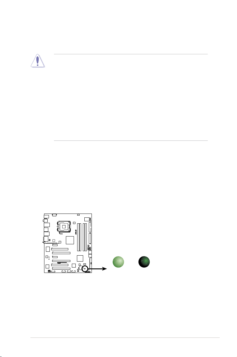
ASUS P5E3 Deluxe/WiFi-AP@n 2-1
Onboard LED
The motherboard comes with a standby power LED. The green LED lights up
to indicate that the system is ON, in sleep mode, or in soft-off mode. This is a
reminder that you should shut down the system and unplug the power cable before
removing or plugging in any motherboard component. The illustration below shows
the location of the onboard LED.
2.1 Before you proceed
Take note of the following precautions before you install motherboard components
or change any motherboard settings.
• Unplug the power cord from the wall socket before touching any
component.
• Use a grounded wrist strap or touch a safely grounded object or
a metal object, such as the power supply case, before handling
components to avoid damaging them due to static electricity.
• Hold components by the edges to avoid touching the ICs on them.
• Whenever you uninstall any component, place it on a grounded
antistatic pad or in the bag that came with the component.
• Before you install or remove any component, ensure
that the ATX power supply is switched off or the power cord is detached
from the power supply. Failure to do so may cause severe damage to the
motherboard, peripherals, and/or components.
P5E3 DELUXE
®
P5E3 DELUXE/WiFi-AP@n
Onboard LED
SB_PWR
ON
Standby
Power
OFF
Powered
Off
Page 28
2-2 Chapter 2: Hardware information
2.2 Motherboard overview
Before you install the motherboard, study the conguration of your chassis to
ensure that the motherboard ts into it.
Make sure to unplug the power cord before installing or removing the
motherboard. Failure to do so can cause you physical injury and damage
motherboard components.
DO NOT overtighten the screws! Doing so can damage the motherboard.
2.2.1 Placement direction
When installing the motherboard, make sure that you place it into the chassis in the
correct orientation. The edge with external ports goes to the rear part of the chassis
as indicated in the image below.
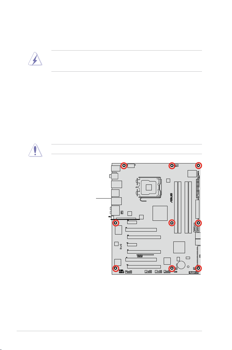
2.2.2 Screw holes
Place nine (9) screws into the holes indicated by circles to secure the motherboard
to the chassis.
Place this side towards
the rear of the chassis
P5E3 DELUXE
®
Page 29
ASUS P5E3 Deluxe/WiFi-AP@n 2-3
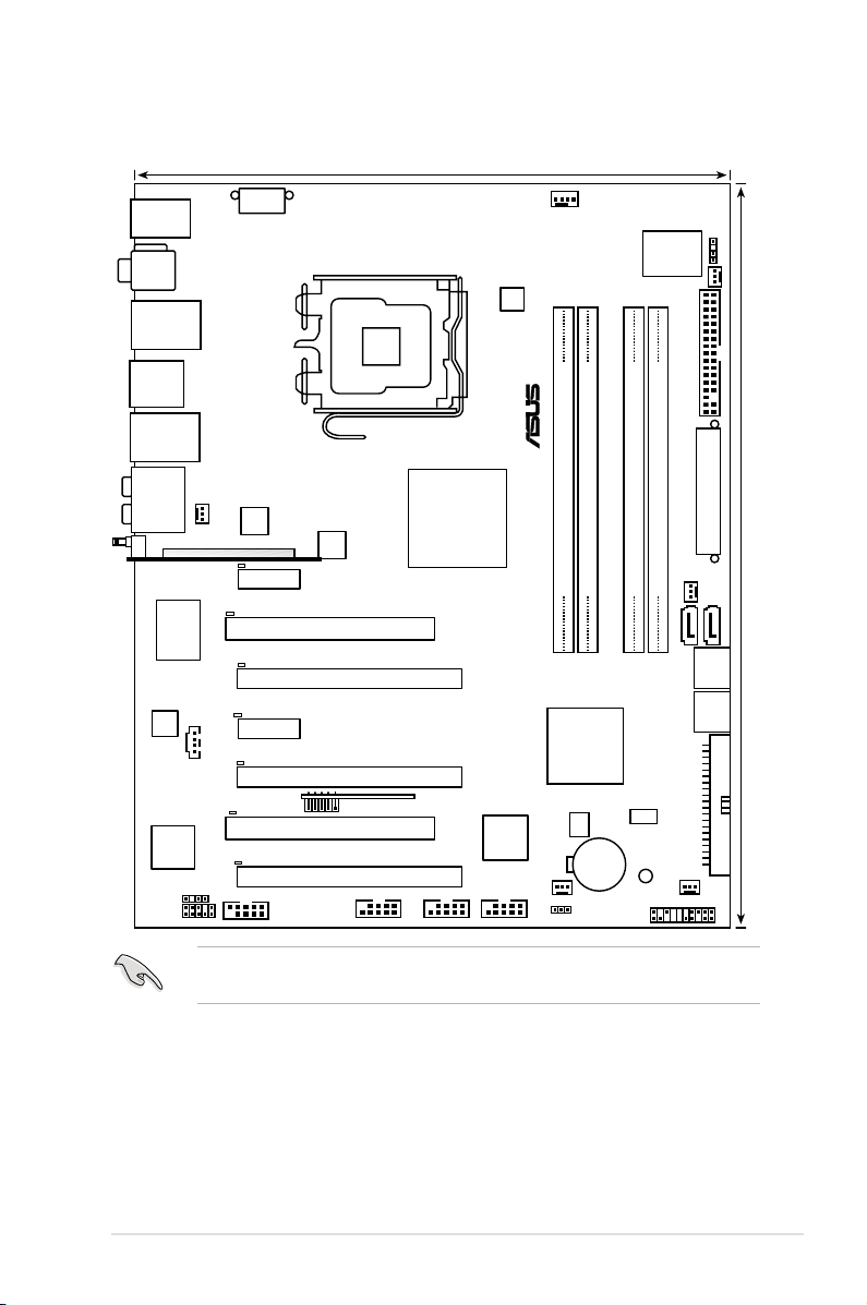
2.2.3 Motherboard layout
Refer to
2.7 Connectors
for more information about rear panel connectors and
internal connectors.
PANEL
P5E3 DELUXE
®
AAFP
CHASSIS
24.5cm (9.6in)
30.5cm (12.0in)
CPU_FAN
DDR3 DIMM_B1 (64 bit,240-pin module)
CHA_FAN4
FLOPPY
Super
I/O
agere
L-FW3227-100
CD
PCIEX1_2
PCIEX16_3
CLRTC
Intel
®
ICH9R
EATXPWR
CR2032 3V
Lithium Cell
CMOS Power
Intel
®
X38
PCI1
USB1112
LAN1_USB12
KB_USB56
LAN2_USB34
PCI2
JMB363
CHA_FAN1
RTL8110SC
SPDIF_OUT
LGA775
CHA_FAN3
IE1394_2 USB78
EATX12V
AD1988B
88E8056
PWR_FAN
CHA_FAN2
SATA34
AUDIO
F_ESATA12
SPDIF_O12
COM1
BIOS
SB_PWR
DET_X1_2
DET_X16_3
DET_PCI2
DET_PCI1
PCIEX16_2
DET_X16_2
PCIEX16_1
DET_X16_1
PCIEX1_1
DET_X1_1
SATA1
SATA2
SATA56
PRI_EIDE
WFG
ICS
DDR3 DIMM_B2 (64 bit,240-pin module)
DDR3 DIMM_A1 (64 bit,240-pin module)
DDR3 DIMM_A2 (64 bit,240-pin module)
USB910_ASAP
ASM
8283
EPU
Page 30
2-4 Chapter 2: Hardware information
2.2.4 Layout contents
Slots Page
1. DDR3 DIMM slots 2-13
2. PCI slots
2-20
3. PCI Express x 1 slots
2-20
4. PCI Express x16 slots 2-20
Jumper Page
1. Clear RTC RAM (3-pin CLRTC) 2-22
Rear panel connectors Page
1. PS/2 keyboard port (purple) 2-23
2. Coaxial S/PDIF Out port
2-23
3. LAN 1 (RJ-45) port
2-23
4. IEEE 1394a port
2-23
5. LAN 2 (RJ-45) port
2-23
6. Center/Subwoofer port (orange)
2-23
7. Rear Speaker Out port (black)
2-23
8. Line In port (light blue)
2-23
9. Line Out port (lime)
2-23
10. Wireless LAN ports
2-24
11. Wireless LAN Activity LED
2-24
12. Microphone port (pink)
2-24
13. Side Speaker Out port (gray)
2-24
14. USB 2.0 ports 1 and 2
2-24
15. External SATA port 1/2
2-24
16. USB 2.0 ports 3 and 4
2-25
17. Optical S/PDIF Out port
2-25
18. USB 2.0 ports 5 and 6
2-25
Page 31

ASUS P5E3 Deluxe/WiFi-AP@n 2-5
Internal connectors Page
1. Floppy disk drive connector (34-1 pin FLOPPY) 2-26
2. IDE connector (40-1 pin PRI_EIDE))
2-27
3. ICH9R Serial ATA connectors (7-pin SATA1-6[red])
2-28
4. USB connectors (10-1 pin USB78, USB910, USB1112)
2-29
5. IEEE 1394a port connector (10-1 pin IE1394_2)
2-29
6. CPU, chassis and power fan connectors
(4-pin CPU_FAN, 3-pin CHA_FAN1-4, 3-pin PWR_FAN)
2-30
7. Chassis intrusion connector (4-1 pin CHASSIS)
2-31
8. ATX power connectors (24-pin EATXPWR, 2x4-pin EATX12V)
2-31
9. Front panel audio connector (10-1 pin AAFP)
2-32
10. Optical drive audio connector (4-pin CD)
2-33
11. Digital audio connector (4-1 pin SPDIF, for ASUS HDMI card)
2-33
12. System panel connector (20-8 pin PANEL)
2-34
13. ASUS Q-Connector (system panel)
2-35
Page 32

2-6 Chapter 2: Hardware information
2.3 Central Processing Unit (CPU)
The motherboard comes with a surface mount LGA775 socket designed for the
Intel® Core™2 Quad / Core™2 Extreme / Core™2 Duo / Pentium® Extreme / Pentium® D /
Pentium® 4 Processors.
•
Upon purchase of the motherboard, make sure that the PnP cap is on
the socket and the socket contacts are not bent. Contact your retailer
immediately if the PnP cap is missing, or if you see any damage to the PnP
cap/socket contacts/motherboard components. ASUS will shoulder the cost
of repair only if the damage is shipment/transit-related.
•
Keep the cap after installing the motherboard. ASUS will process Return
Merchandise Authorization (RMA) requests only if the motherboard comes
with the cap on the LGA775 socket.
• The product warranty does not cover damage to the socket contacts
resulting from incorrect CPU installation/removal, or misplacement/loss/
incorrect removal of the PnP cap.
• Make sure that all power cables are unplugged before installing the CPU.
• If installing a dual-core CPU, connect the chassis fan cable to the
CHA_FAN1 connector to ensure system stability.
• Due to the chipset limitation, we recommend you use FSB 800MHz CPU or
above.
Page 33
ASUS P5E3 Deluxe/WiFi-AP@n 2-7
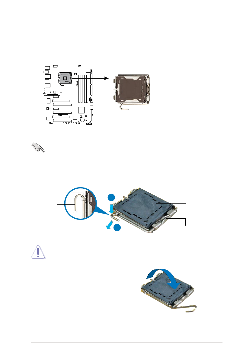
3. Lift the load lever in the direction of
the arrow to a 135º angle.
2. Press the load lever with your thumb (A), then move it to the left (B) until it is
released from the retention tab.
Retention tab
Load lever
This side of the socket box
should face you.
PnP cap
A
B
To prevent damage to the socket pins, do not remove the PnP cap unless you
are installing a CPU.
2.3.1 Installing the CPU
To install a CPU:
1. Locate the CPU socket on the motherboard.
Before installing the CPU, make sure that the cam box is facing towards you
and the load lever is on your left.
P5E3 DELUXE
®
P5E3 DELUXE/WiFi-AP@n
CPU Socket 775
Page 34
2-8 Chapter 2: Hardware information
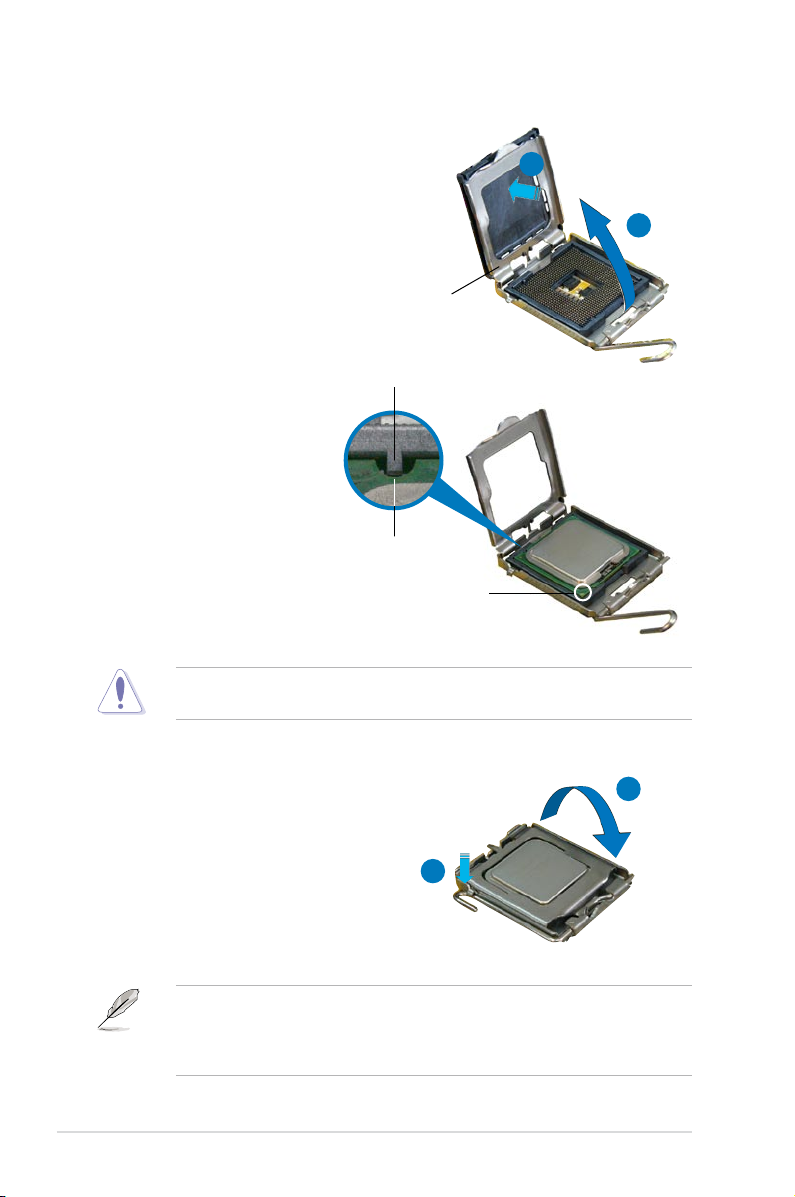
5. Position the CPU over the
socket, making sure that
the gold triangle is on the
bottom-left corner of the
socket then t the socket
alignment key into the
CPU notch.
Alignment key
Gold triangle mark
6. Close the load plate (A), then
push the load lever (B) until it
snaps into the retention tab.
7. If installing a dual-core CPU,
connect the chassis fan cable
to the CHA_FAN1 connector to
ensure system stability.
A
B
The CPU ts in only one correct orientation. DO NOT force the CPU into the
socket to prevent bending the connectors on the socket and damaging the CPU!
The motherboard supports Intel® LGA775 processors with the Intel® Enhanced
Memory 64 Technology (EM64T), Enhanced Intel SpeedStep® Technology
(EIST), and Hyper-Threading Technology. Refer to the Appendix for more
information on these CPU features.
4. Lift the load plate with your thumb
and forenger to a 100º angle (A),
then push the PnP cap from the load
plate window to remove (B).
Load plate
A
B
CPU notch
Page 35
ASUS P5E3 Deluxe/WiFi-AP@n 2-9
Fastener
Motherboard hole
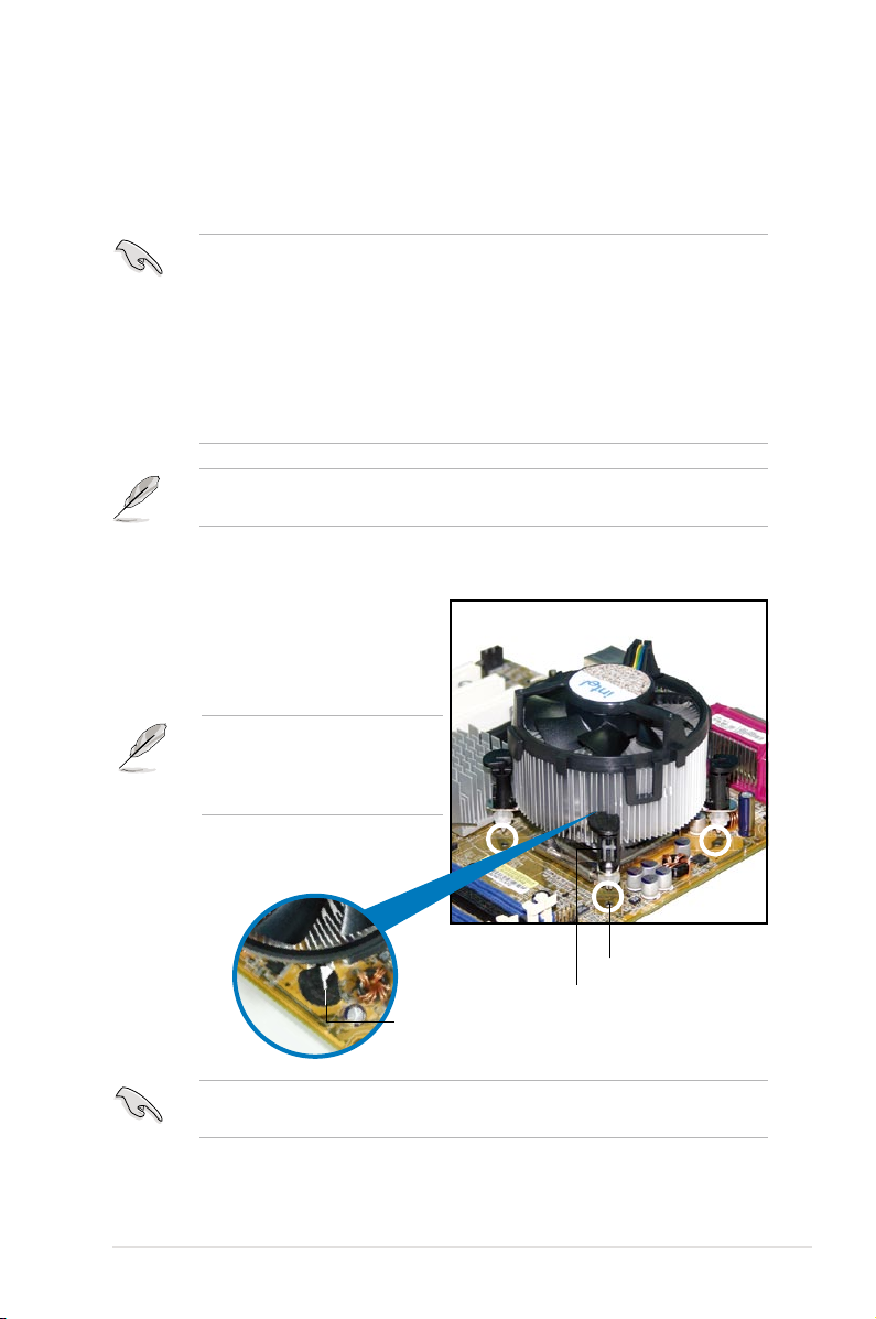
2.3.2 Installing the CPU heatsink and fan
The Intel® LGA775 processor requires a specially designed heatsink and fan
assembly to ensure optimum thermal condition and performance.
To install the CPU heatsink and fan:
1. Place the heatsink on top of the
installed CPU, making sure that the
four fasteners match the holes on
the motherboard.
•
When you buy a boxed Intel® processor, the package includes the CPU fan
and heatsink assembly. If you buy a CPU separately, make sure that you
use only Intel®-certied multi-directional heatsink and fan.
•
Your Intel® LGA775 heatsink and fan assembly comes in a push-pin design
and requires no tool to install.
•
If you purchased a separate CPU heatsink and fan assembly, make sure
that you have properly applied Thermal Interface Material to the CPU
heatsink or CPU before you install the heatsink and fan assembly.
Make sure that you have installed the motherboard to the chassis before you
install the CPU fan and heatsink assembly.
Make sure to orient each fastener with the narrow end of the groove pointing
outward. (The photo shows the groove shaded for emphasis.)
Orient the heatsink and fan
assembly such that the CPU fan
cable is closest to the CPU fan
connector.
Narrow end
of the groove
Page 36

2-10 Chapter 2: Hardware information
3. Connect the CPU fan cable to the connector on the motherboard labeled
CPU_FAN.
DO NOT forget to connect the CPU fan connector! Hardware monitoring errors can
occur if you fail to plug this connector.
2. Push down two fasteners at a time in
a diagonal sequence to secure the
heatsink and fan assembly in place.
B
A
A
A
B
B
A
B
P5E3 DELUXE
®
P5E3 DELUXE/WiFi-AP@n
CPU fan connector
CPU_FAN
GND
CPU FAN PWR
CPU FAN IN
CPU FAN PWM
Page 37

ASUS P5E3 Deluxe/WiFi-AP@n 2-11
2.3.3 Uninstalling the CPU
heatsink and fan
To uninstall the CPU heatsink and fan:
1. Disconnect the CPU fan cable from
the connector on the motherboard.
2. Rotate each fastener
counterclockwise.
3. Pull up two fasteners at a time in
a diagonal sequence to disengage
the heatsink and fan assembly from
the motherboard.
B
B
A
A
A
A
B
B
4. Carefully remove the heatsink
and fan assembly from the
motherboard.
Page 38

2-12 Chapter 2: Hardware information
5. Rotate each fastener clockwise to
ensure correct orientation when
reinstalling.
Narrow end of the groove
Refer to the documentation in the boxed or stand-alone CPU fan package for
detailed information on CPU fan installation.
The narrow end of the groove
should point outward after resetting.
(The photo shows the groove
shaded for emphasis.)
Page 39
ASUS P5E3 Deluxe/WiFi-AP@n 2-13
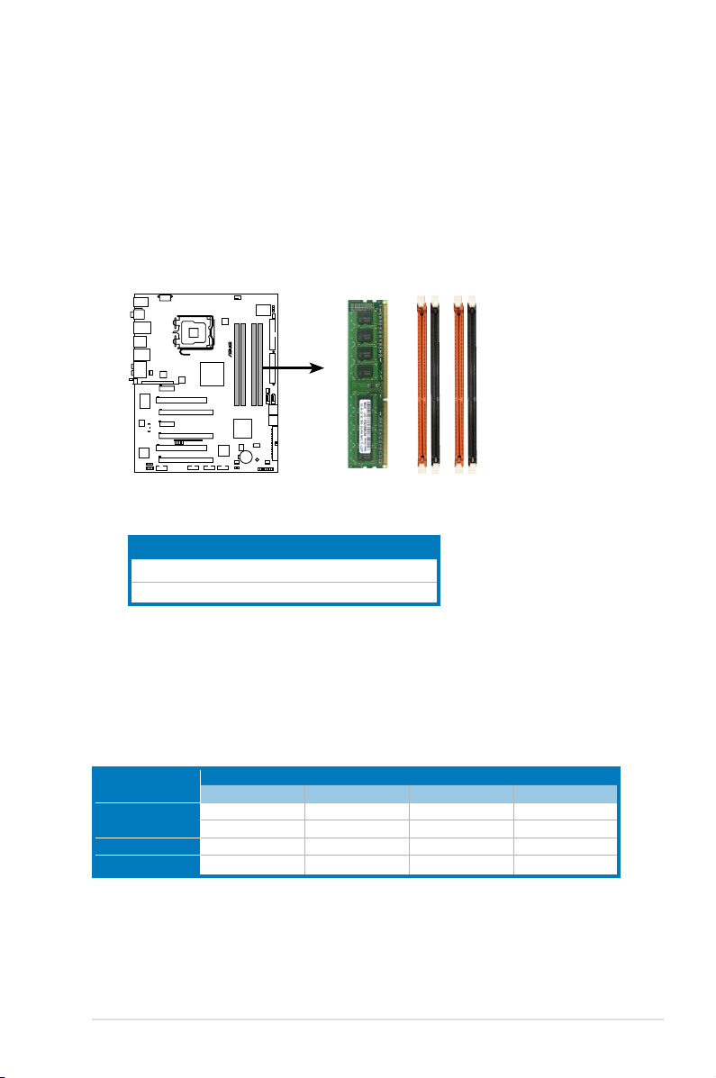
2.4 System memory
2.4.1 Overview
The motherboard comes with four Double Data Rate 3 (DDR3) Dual Inline Memory
Modules (DIMM) sockets.
A DDR3 module has the same physical dimensions as a DDR2 DIMM but is
notched differently to prevent installation on a DDR2 DIMM socket. DDR3 modules
are developed for better performance with less power consumption.
The gure illustrates the location of the DDR3 DIMM sockets:
P5E3 DELUXE
®
P5E3 DELUXE/WiFi-AP
240-pin DDR3 DIMM sockets
DIMM_A2
DIMM_A1
DIMM_B2
DIMM_B1
Channel Sockets
Channel A DIMM_A1 and DIMM_A2
Channel B DIMM_B1 and DIMM_B2
2.4.2 Memory congurations
You may install 512 MB, 1 GB, and 2 GB unbuffered ECC, non-ECC DDR3 DIMMs
into the DIMM sockets.
Recommend memory conguration
Mode
Sockets
DIMM_A1 DIMM_B1 DIMM_A2 DIMM_B2
Single-channel
- - - populated
- - populated -
Dual-channel (1) populated populated - -
Dual-channel (2) populated populated populated populated
Page 40
2-14 Chapter 2: Hardware information
• If you install four 1 GB memory modules, the system may detect less than
3 GB of total memory because of address space allocation for other critical
functions. This limitation applies to Windows Vista 32-bit/Windows XP 32-bit
version operating system since it does not support PAE (Physical Address
Extention) mode.
• If you install Windows Vista 32-bit/Windows XP 32-bit version operating
system, we recommend that you install less than 3GB of total memory.
Notes on memory limitations
• Due to chipset limitation, this motherboard can only support up to
8 GB on the operating systems listed below. You may install a maximum of
2 GB DIMMs on each slot.
64-bit
Windows XP Professional x64 Edition
Windows Vista x64 Edition
• You may install varying memory sizes in Channel A and Channel B. The
system maps the total size of the lower-sized channel for the dual-channel
conguration. Any excess memory from the higher-sized channel is then
mapped for single-channel operation.
• Always install DIMMs with the same CAS latency. For optimum
compatibility, it is recommended that you obtain memory modules from the
same vendor.
• Due to chipset resource allocation, the system may detect less than 8 GB
system memory when you installed four 2 GB DDR3 memory modules.
P5E3 Deluxe Motherboard Qualied Vendors Lists (QVL)
DDR3-1800MHz capability
Size Vendor Model CL
Chip
Brand
SS/
DS
Component
DIMM socket support
(Optional)
A* B* C*
1GB CORSAIR TWIN3X2048-1800C7DF G 7 Micon SS Heatsink • •
1GB OCZ OCZ3P18002GK 8 Micon SS Heatsink • •
Page 41
ASUS P5E3 Deluxe/WiFi-AP@n 2-15
P5E3 Deluxe WiFi-AP@n Motherboard Qualied Vendors Lists
(QVL) DDR3-1600MHz capability
Size Vendor Chip No. CL Chip Brand
SS/
DS
Component
DIMM socket support
(Optional)
A* B* C*
1GB CORSAIR
CM3X10241600C7DHXIN
7 Micon SS Heatsink • •
1GB OCZ OCZ3P16002GK 7 Micon SS Heatsink • •
1GB A-DATA DDR3-1600X 7 Micon SS Heatsink • •
1GB SuperTalent W1600X2G7 7 Micon SS Heatsink • •
Size Vendor Chip No. CL Chip Brand
SS/
DS
Part No.
DIMM socket
support (Optional)
A* B* C*
512MB ELPIDA J5308BASE-DG-E 8 ELPIDA SS
EBJ51UD8BAFADG-E
• • •
1GB SAMSUNG K4B1G0846C-ZCF8 8 SAMSUNG SS M378B2873CZ0-CG9 • •
1GB OCZ Heat-Sink Package 7-7-7-20 N/A DS OCZ3P13332GK • • •
P5E3 Deluxe WiFi-AP@n Motherboard Qualied Vendors Lists
(QVL) DDR3-1333MHz capability
Size Vendor Chip No. CL Chip Brand
SS/
DS
Part No.
DIMM socket
support (Optional)
A* B* C*
512MB Qimonda IDSH51-03A1F1C-10F N/A QIMONDA SS IMSH51U03A1F1C-10F • • •
1GB Qimonda IDSH51-03A1F1C-10F N/A QIMONDA DS IMSH1GU13A1F1C-10F • •
512MB ELPIDA J5308BASE-AC-E 8 ELPIDA SS EBJ51UD8BAFA-AG-E • • •
1GB ELPIDA J5308BASE-AC-E 8 ELPIDA DS EBJ11UD8BAFA-AG-E • •
512MB NANYA NT5CB64M8AN-BE N/A NANYA SS NT512C64B88A0NY-BF • • •
1GB MICRON D9GTR 7 MICRON SS
MT8JTF12864AY1G1BZES
• •
2GB MICRON Z9HWQ 7 MICRON DS
MT16JTF25664AY1G1BYES
•
1GB SAMSUNG K4B1G0846C-ZCF8 7-7-7 SAMSUNG SS M378B2873CZ0-CF8 • •
1GB SAMSUNG K4B1G0846C-ZCG8 8 SAMSUNG SS M378B2873CZ0-CG8 • •
2GB SAMSUNG K4B1G0846C-ZCF8 7 SAMSUNG DS M378B5673CZ0-CF8 •
1GB SAMSUNG K4B1G0846C-ZCF8 7 SAMSUNG SS M391B2873CZ0-CF8 • •
512MB Kingston IDSH51-03A1F1C-10F N/A QIMONDA SS KVR1066D3N7/512 • • •
1GB Kingston J5308BASE-AC-E 7 ELPIDA DS KVR1066D3N7/1G • •
512MB Kingston J5308BASE-AC-E 7 ELPIDA SS KVR1066D3N7/512 • • •
1GB CORSAIR Heat-Sink Package 7 N/A DS CM3X1024-1066C7 • •
1GB Hynix HY5TQ1G831ZNFP-G7 7 HYNIX SS HYMT112U64ZNF8-G7 • •
2GB Hynix HY5TQ1G831ZNFP-G7 7 HYNIX DS HYMT125U64ZNF8-G7 •
512MB GEIL Heat-Sink Package 6 N/A SS G31GB1066C6DC • • •
1GB WINTEC IDSH51-03A1F1C-10F 7 QIMONDA DS 3DU3191A-10 • • •
P5E3 Deluxe WiFi-AP@n Motherboard Qualied Vendors Lists
(QVL) DDR3-1066MHz capability
Page 42

2-16 Chapter 2: Hardware information
Side(s): SS - Single-sided DS - Double-sided
DIMM support:
A - Supports one module inserted into either slot as Single-channel memory conguration.
B - Supports two modules inserted into either the orange slots or the black slots as one pair of Dual-
channel memory conguration.
C - Supports four modules inserted into both the orange slots and the black slots as two pairs of Dual-
channel memory conguration.
Visit the ASUS website for the latest QVL.
P5E3 Deluxe WiFi-AP@n Motherboard Qualied Vendors Lists
(QVL) DDR3-800MHz capability
Size Vendor Chip No. CL Chip Brand
SS/
DS
Part No.
DIMM socket
support (Optional)
A* B* C*
512MB ELPIDA J5308BASE-AC-E 6 ELPIDA SS EBJ51UD8BAFA-8C-E • • •
1GB ELPIDA J5308BASE-AC-E 6 ELPIDA DS EBJ11UD8BAFA-8C-E • • •
512MB NANYA NT5CB64M8AN-25D N/A NANYA SS
NT512C64B88A0NY25D
• • •
1GB NANYA NT5CB64M8AN-25D N/A NANYA DS
NT1GC64B8HA0NY25D
• • •
1GB Qimonda IDSH51-03A1F1C-08E N/A QIMONDA DS IMSH1GU13A1F1C-08E • • •
512MB Qimonda IDSH51-03A1F1C-08D N/A Qimonda SS IMSH51U03A1F1C-08D • • •
512MB Qimonda IDSH51-03A1F1C-08E N/A Qimonda SS IMSH51U03A1F1C-08E • • •
1GB Hynix HY5TQ1G831ZNF-S6 N/A Hynix SS HYMT112U64ZNF8-S6 • • •
2GB Hynix HY5TQ1G831ZNF-S5 N/A Hynix DS HYMT125U64ZNF8-S5 • • •
Page 43
ASUS P5E3 Deluxe/WiFi-AP@n 2-17
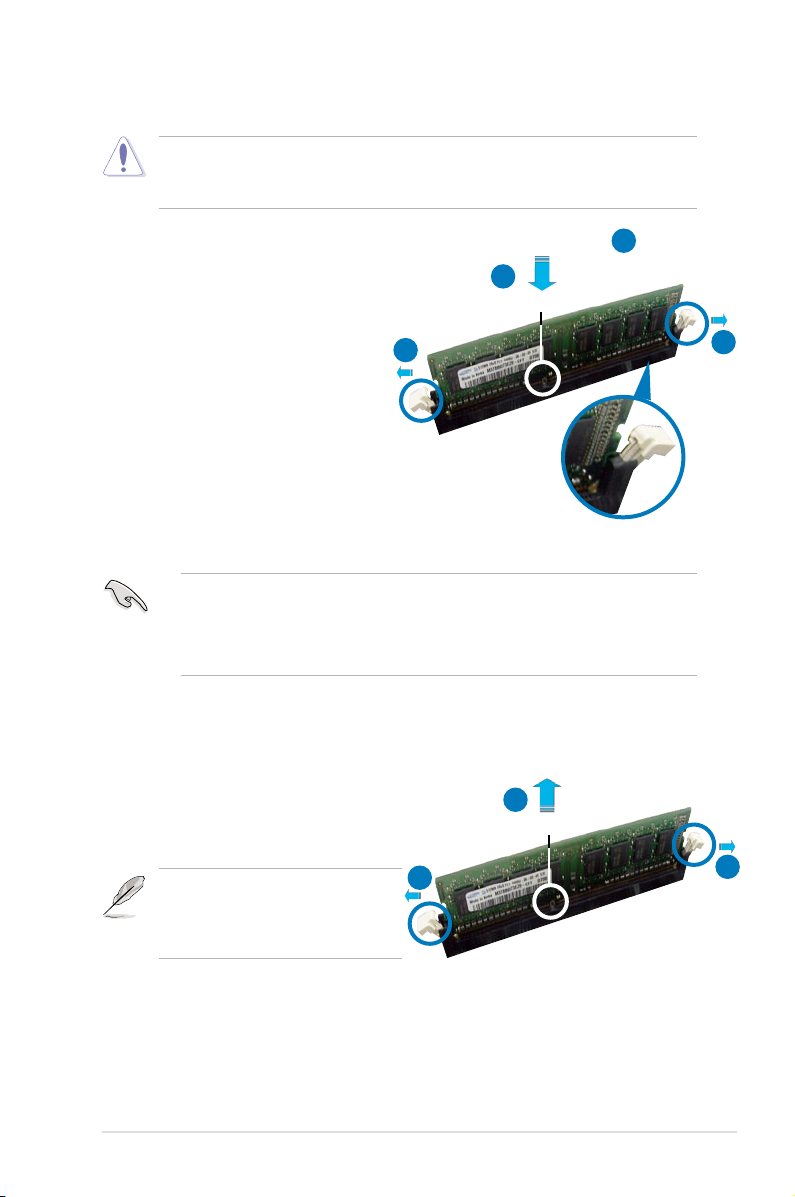
2.4.3 Installing a DIMM
Unplug the power supply before adding or removing DIMMs or other system
components. Failure to do so can cause severe damage to both the motherboard
and the components.
To install a DIMM:
1. Unlock a DIMM socket by pressing
the retaining clips outward.
2. Align a DIMM on the socket
such that the notch on the DIMM
matches the break on the socket.
3. Firmly insert the DIMM into the
socket until the retaining clips
snap back in place and the DIMM
is properly seated.
2.4.4 Removing a DIMM
To remove a DIMM:
1. Simultaneously press the retaining
clips outward to unlock the DIMM.
2. Remove the DIMM from the socket.
• A DDR3 DIMM is keyed with a notch so that it ts in only one direction. DO
NOT force a DIMM into a socket to avoid damaging the DIMM.
• The DDR3 DIMM sockets do not support DDR and DDR2 DIMMs. DO NOT
install DDR or DDR2 DIMMs to the DDR3 DIMM sockets.
Unlocked retaining clip
DDR3 DIMM notch
Support the DIMM lightly with your
ngers when pressing the retaining
clips. The DIMM might get damaged
when it ips out with extra force.
1
2
3
2
1
DDR3 DIMM notch
1
1
Page 44

2-18 Chapter 2: Hardware information
2.5 Expansion slots
In the future, you may need to install expansion cards. The following sub-sections
describe the slots and the expansion cards that they support.
2.5.1 Installing an expansion card
To install an expansion card:
1. Before installing the expansion card, read the documentation that came with
it and make the necessary hardware settings for the card.
2. Remove the system unit cover (if your motherboard is already installed in a
chassis).
3. Remove the bracket opposite the slot that you intend to use. Keep the screw
for later use.
4. Align the card connector with the slot and press rmly until the card is
completely seated on the slot.
5. Secure the card to the chassis with the screw you removed earlier.
6. Replace the system cover.
2.5.2 Conguring an expansion card
After installing the expansion card, congure it by adjusting the software settings.
1. Turn on the system and change the necessary BIOS settings, if any. See
Chapter 4 for information on BIOS setup.
2. Assign an IRQ to the card. Refer to the tables on the next page.
3. Install the software drivers for the expansion card.
Make sure to unplug the power cord before adding or removing expansion
cards. Failure to do so may cause you physical injury and damage motherboard
components.
When using PCI cards on shared slots, ensure that the drivers support “Share
IRQ” or that the cards do not need IRQ assignments. Otherwise, conicts will arise
between the two PCI groups, making the system unstable and the card inoperable.
Refer to the table on the next page for details.
Page 45

ASUS P5E3 Deluxe/WiFi-AP@n 2-19
2.5.3 Interrupt assignments
Standard interrupt assignments
IRQ Priority Standard Function
0 1 System Timer
1 2 Keyboard Controller
2 — Re-direct to IRQ#9
3 9 IRQ holder for PCI steering*
4 12 Communications Port (COM1)*
5 13 IRQ holder for PCI steering*
6 14 Floppy Disk Controller
7 15 Printer Port (LPT1)*
8 3 System CMOS/Real Time Clock
9 4 IRQ holder for PCI steering*
10 5 IRQ holder for PCI steering*
11 6 IRQ holder for PCI steering*
12 7 PS/2 Compatible Mouse Port*
13 8 Numeric Data Processor
14 10 Primary IDE Channel
15 11 Secondary IDE Channel
* These IRQs are usually available for PCI devices.
IRQ assignments for this motherboard
A B C D E F G H
PCI slot 1 shared — — — — — — —
PCI slot 2 — shared — — — — — —
LAN (8110SC) shared — — — — — — —
SATA (363) shared — — — — — — —
LAN(8056) — shared — — — — — —
PCIe x16 1 shared — — — — — — —
PCIe x16 2 shared — — — — — — —
PCIe x16 3 — — shared
PCIe x1 1 — — shared — — — — —
PCIe x1 2 — — — shared — — — —
USB controller 1 — — — — — — — shared
USB controller 2 — — — shared — — — —
USB controller 3 — — shared — — — — —
USB controller 4 shared — — — — — — —
USB controller 5 shared — — — — — — —
USB controller 6 shared
USB 2.0 controller 1 — — — — — — — shared
USB 2.0 controller 2 — — shared — — — — —
SATA controller 1 — — shared — — — — —
SATA controller 2 — shared — — — — — —
Page 46

2-20 Chapter 2: Hardware information
2.5.4 PCI slots
The PCI slots support cards such as a LAN card, SCSI card, USB card, and other
cards that comply with PCI specications. Refer to the gure below for the location
of the slot.
2.5.5 PCI Express x1 slots
This motherboard supports PCI Express x1 network cards, SCSI cards and other
cards that comply with the PCI Express specications. Refer to the gure below for
the location of the slot.
2.5.6 PCI Express 2.0 x16 slots
This motherboard has three PCI Express x16 slots that support PCI Express x16
graphic cards complying with the PCI Express specications. With two graphics
cards installed, the motherboard can enable dual-display. Two (blue slots) of the
three PCI Express x16 slots support PCIe x16 2.0 devices.
This motherboard supports two ATI CrossFire™ PCI Express x16 graphics cards
that comply with the PCI Express specications.
PCIe 2.0 x16_1 slot (blue, @x16)
PCI Express x1_1 slot
PCI Express x1_2 slot
PCIe 2.0 x16_2 slot (blue, @x16)
PCI slot 1
PCIe x16_3 slot (black, @x4 or x1)
We recommend that you install a VGA card on the primary (blue) PCI Express slots,
and install any other PCI Express device on the Universal PCI Express slot (black).
PCI slot 2
Page 47

ASUS P5E3 Deluxe/WiFi-AP@n 2-21
2.5.7 AI Slot Detector
This motherboard comes with on-board LEDs that light up when the PCIE/
PCI devices are not correctly installed. This is a reminder that you should
reinstall these devices. Refer to the gure on the right for the location of the
LEDs.
• The PCIEx16_1 slot (blue)
supports PCIE x16 cards
only. The AI Slot Detector
lights up when you install a
x1 or x4 card to this slot.
• When the AI Slot Detector
lights up for incorrect
installation, make sure to
shut down the power supply
unit before reinstalling the
card to avoid electrical shock
hazard.
Primary PCI Express x16 slots
The primary PCI Express x16 slots support PCI Express x16 graphic cards that
comply with the PCI Express specications.
Universal PCI Express slot (max. x4 mode)
This motherboard also supports a Universal PCI Express slot with a maximum
speed of 2 GB/s. The operating frequency of this slot changes, depending on the
type of PCI Express card you install. Refer to the table below for details.
If you install two VGA cards, we recommend that you plug the rear chassis fan cable
to the motherboard connector labeled CHA_FAN1 for better thermal environment.
See page 2-30 for the connector location.
Some PCI Express devices cannot operate on x4/x1 mode.
Options for Universal PCI Express operating speed
PCI Express slot
Auto Automatically optimizes performance
and functionality according to devices
installed
x4 mode [fast] User gets the best performance but this
mode disables the PCI Express x1 slot
x1 mode [compatible] Always runs at PCI Express x1 speed
P5E3 DELUXE
®
P5E3 DELUXE/WiFi-AP@n
Slot Detector
DET_X1_1
DET_PCI1
DET_X16_1
DET_X1_2
DET_X16_2
DET_PCI2
DET_X16_3
Page 48
2-22 Chapter 2: Hardware information
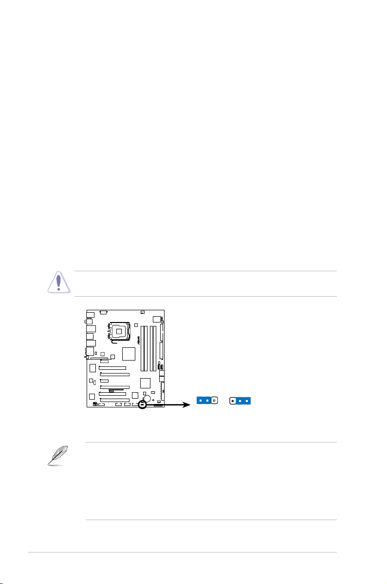
2.6 Jumper
1. Clear RTC RAM (CLRTC)
This jumper allows you to clear the Real Time Clock (RTC) RAM in CMOS.
You can clear the CMOS memory of date, time, and system setup parameters
by erasing the CMOS RTC RAM data. The onboard button cell battery
powers the RAM data in CMOS, which include system setup information such
as system passwords.
To erase the RTC RAM:
1. Turn OFF the computer and unplug the power cord.
2. Remove the onboard battery.
3. Move the jumper cap from pins 1-2 (default) to pins 2-3. Keep the cap on
pins 2-3 for about 5~10 seconds, then move the cap back to pins 1-2.
4. Reinstall the battery.
5. Plug the power cord and turn ON the computer.
6. Hold down the <Del> key during the boot process and enter BIOS setup
to re-enter data.
• You do not need to clear the RTC when the system hangs due to
overclocking. For system failure due to overclocking, use the C.P.R. (CPU
Parameter Recall) feature. Shut down and reboot the system so the BIOS
can automatically reset parameter settings to default values.
• Due to the chipset behavior, AC power off is required to enable C.P.R.
function. You must turn off and on the power supply or unplug and plug the
power cord before rebooting the system.
Except when clearing the RTC RAM, never remove the cap on CLRTC jumper
default position. Removing the cap will cause system boot failure!
P5E3 DELUXE
®
P5E3 DELUXE/WiFi-AP@n
Clear RTC RAM
CLRTC
Normal Clear RTC
(Default)
1 2 2 3
Page 49

ASUS P5E3 Deluxe/WiFi-AP@n
2-23
2.7 Connectors
2.7.1 Rear panel connectors
1. PS/2 keyboard port (purple). This port is for a PS/2 keyboard.
2. Coaxial S/PDIF Out port.
This port connects an external audio output device
via a coaxial S/PDIF cable.
3. LAN 1 (RJ-45) port.
This Marvell® LAN port allows Gigabit connection to a
Local Area Network (LAN) through a network hub. Refer to the table below
for the LAN port LED indications.
4. IEEE 1394a port.
This 6-pin IEEE 1394a port provides high-speed
connectivity for audio/video devices, storage peripherals, PCs, or portable
devices.
5. LAN 2 (RJ-45) port.
This Realtek® LAN port allows Gigabit connection to a
Local Area Network (LAN) through a network hub. Refer to the table below
for the LAN port LED indications.
Activity Link LED Speed LED
Status Description Status Description
OFF No link OFF 10 Mbps connection
ORANGE Linked ORANGE 100 Mbps connection
BLINKING Data activity GREEN 1 Gbps connection
LAN port LED indications
SPEED
LED
ACT/LINK
LED
LAN port
6. Center/Subwoofer port (orange).
This port connects the center/subwoofer
speakers.
7. Rear Speaker Out port (black).
This port connects the rear speakers in a
4-channel, 6-channel, or 8-channel audio conguration..
8. Line In port (light blue).
This port connects the tape, CD, DVD player, or
other audio sources.
9. Line Out port (lime).
This port connects a headphone or a speaker. In
4-channel, 6-channel, and 8-channel conguration, the function of this port
becomes Front Speaker Out.
2
1 54 6
15 1213
8 97
17 14
3
1618
10
11
Page 50
2-24 Chapter 2: Hardware information
10. Wireless LAN ports. These ports are on the onboard wireless LAN module
that allow you to set up a wireless network and exchange information
with other wireless devices without tagling cables and wires. Connect the
moveable omni-directional antennas to these ports.
11. Wireless LAN Activity LED
. The wireless module comes with an activity
LED.
12. Microphone port (pink).
This port connects a microphone.
13. Side Speaker Out port (gray).
This port connects the side speakers in an
8-channel audio conguration.
14. USB 2.0 ports 1 and 2.
These 4-pin Universal Serial Bus (USB) ports are
available for connecting USB 2.0 devices.
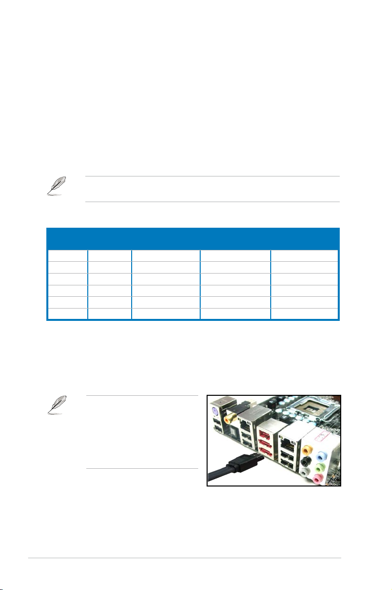
15. External SATA port 1/2. These port connect to an external a Serial ATA hard
disk drive. To congure a RAID0 or RAID1, connect external Serial ATA hard
disk drives to the External SATA port 1 and 2.
Refer to the audio conguration table below for the function of the audio ports in
2, 4, 6, or 8-channel conguration.
Audio 2, 4, 6, or 8-channel conguration
Port Headset
2-channel
4-channel 6-channel 8-channel
Light Blue Line In Line In Line In Line In
Lime Line Out Front Speaker Out Front Speaker Out Front Speaker Out
Pink Mic In Mic In Mic In Mic In
Orange – – Center/Subwoofer Center/Subwoofer
Black – Rear Speaker Out Rear Speaker Out Rear Speaker Out
Gray – – – Side Speaker Out
The external SATA port supports
external SATA 3 Gb/s devices.
Longer cables support higher
power requirements to deliver
signal up to two meters away,
and enables improved hot-swap
function.
Page 51

ASUS P5E3 Deluxe/WiFi-AP@n
2-25
16. USB 2.0 ports 3 and 4. These 4-pin Universal Serial Bus (USB) ports are
available for connecting USB 2.0 devices.
17. Optical S/PDIF Out port
. This port connects an external audio output device
via an optical S/PDIF cable.
18. USB 2.0 ports 5 and 6.
These 4-pin Universal Serial Bus (USB) ports are
available for connecting USB 2.0 devices.
• DO NOT insert different connectors to the external SATA ports.
• DO NOT unplug the external Serial ATA box when a RAID 0 or RAID 1 is
congured.
• Before creating a RAID set using Serial ATA hard disks, make sure that you
have connected the Serial ATA signal cable and installed Serial ATA hard
disk drives; otherwise, you cannot enter the JMicron RAID utility and SATA
BIOS setup during POST.
• If you intend to create a RAID conguration using this connector, set the
J-Micron eSATA/PATA Controller Mode in the BIOS to [RAID]. See section
4.5.3 Onboard Device Conguration for details.
• When using hot-plug and NCQ, set the J-Micron eSATA/PATA Controller
Mode in the BIOS to [AHCI]. See section 4.5.3 Onboard Device
Conguration for details.
• Before creating a RAID set, refer to
5.4.3 JMicron® RAID Conguration or
the manual bundled in the motherboard support DVD.
Page 52
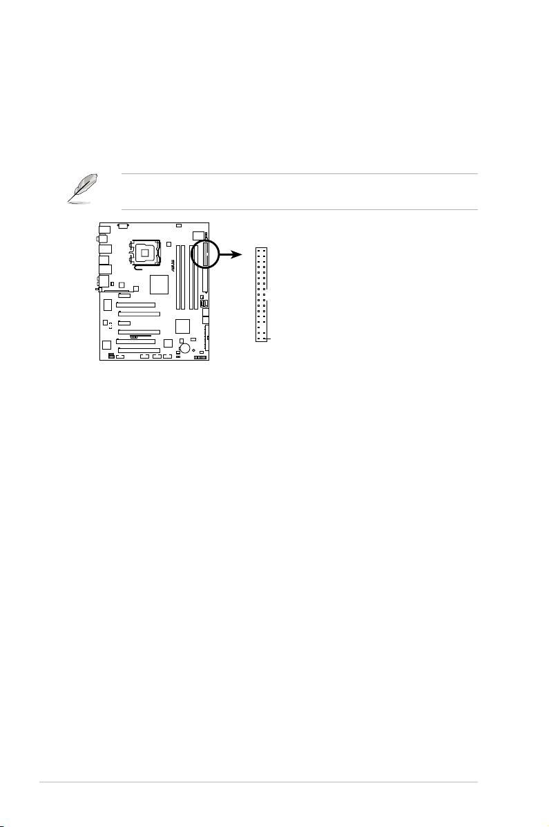
2-26 Chapter 2: Hardware information
2.7.2 Internal connectors
1. Floppy disk drive connector (34-1 pin FLOPPY)
This connector is for the provided oppy disk drive (FDD) signal cable. Insert
one end of the cable to this connector, then connect the other end to the
signal connector at the back of the oppy disk drive.
Pin 5 on the connector is removed to prevent incorrect cable connection when
using a FDD cable with a covered Pin 5.
P5E3 DELUXE
®
P5E3 DELUXE/WiFi-AP@n
Floppy disk drive connector
NOTE: Orient the red markings on
the floppy ribbon cable to PIN 1.
PIN 1
FLOPPY
Page 53

ASUS P5E3 Deluxe/WiFi-AP@n
2-27
Drive jumper setting Mode of
device(s)
Cable connector
Single device Cable-Select or Master - Black
Two devices Cable-Select Master
Black
Slave Gray
Master Master Black or gray
Slave Slave
• Pin 20 on the IDE connector is removed to match the covered hole on the
Ultra DMA cable connector. This prevents incorrect insertion when you
connect the IDE cable.
• Use the 80-conductor IDE cable for Ultra DMA 133/100/66 IDE devices.
If any device jumper is set as “Cable-Select,” make sure all other device
jumpers have the same setting.
2. IDE connector (40-1 pin PRI_E IDE)
The onboard IDE connector is for the Ultra DMA 133/100/66 signal cable.
There are three connectors on each Ultra DMA 133/100/66 signal cable:
blue, black, and gray. Connect the blue connector to the motherboard’s IDE
connector, then select one of the following modes to congure your device.
P5E3 DELUXE
®
P5E3 DELUXE/WiFi-AP@n
IDE connector
NOTE: Orient the red markings
(usually zigzag) on the IDE
ribbon cable to PIN 1.
PRI_EIDE
Page 54

2-28 Chapter 2: Hardware information
Connect the right-angle side
of SATA signal cable to SATA
device. Or you may connect the
right-angle side of SATA cable to
the onboard SATA port to avoid
mechanical conict with huge
graphics cards.
right angle side
•
You must install the Windows® XP Service Pack 1 before using Serial ATA
hard disk drives. The Serial ATA RAID feature (RAID 0, 1, 5, and 10) is
available only if you are using Windows® XP or later version.
•
When using the connectors in Standard IDE mode, connect the primary
(boot) hard disk drive to the SATA1/2/5 connector.
When using hot-plug and NCQ, set the Congure SATA as in the BIOS to
[AHCI]. See section 4.3.6 SATA Conguration for details.
3. ICH9R Serial ATA connectors (7-pin SATA 1-6 [red])
These connectors are for the Serial ATA signal cables for Serial ATA hard disk
drives.
If you installed Serial ATA hard disk drives, you can create a RAID 0, 1, 5,
and 10 conguration with the Intel® Matrix Storage Technology through the
onboard Intel® ICH9R RAID controller.
•
These connectors are set to Standard IDE mode by default. In Standard
IDE mode, you can connect Serial ATA boot/data hard disk drives to these
connectors. If you intend to create a Serial ATA RAID set using these
connectors, set the Congure SATA as item in the BIOS to [RAID]. See
section 4.3.6 SATA Conguration for details.
• Before creating a RAID set, refer to
5.4.3 Intel RAID Conguration or the
manual bundled in the motherboard support DVD.
P5E3 DELUXE
®
P5E3 DELUXE/WiFi-AP@n
SATA connectors
GND
RSATA_TXP1
RSATA_TXN1
GND
RSATA_RXP1
RSATA_RXN1
GND
SATA1
GND
RSATA_TXP2
RSATA_TXN2
GND
RSATA_RXP2
RSATA_RXN2
GND
SATA2
GND
RSATA_TXP3
RSATA_TXN3
GND
RSATA_RXP3
RSATA_RXN3
GND
SATA3
GND
RSATA_TXP4
RSATA_TXN4
GND
RSATA_RXP4
RSATA_RXN4
GND
SATA4
GND
RSATA_TXP5
RSATA_TXN5
GND
RSATA_RXP5
RSATA_RXN5
GND
SATA5
GND
RSATA_TXP6
RSATA_TXN6
GND
RSATA_RXP6
RSATA_RXN6
GND
SATA6
Page 55
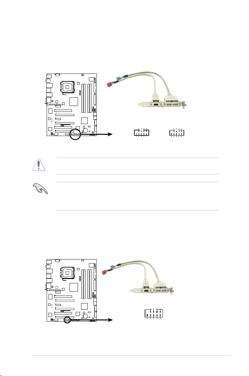
ASUS P5E3 Deluxe/WiFi-AP@n
2-29
4. USB connectors (10-1 pin USB 78, USB 1112)
These connectors are for USB 2.0 ports. Connect the USB module cable
to any of these connectors, then install the module to a slot opening at the
back of the system chassis. These USB connectors comply with USB 2.0
specication that supports up to 480 Mbps connection speed.
Never connect a 1394 cable to the USB connectors. Doing so will damage the
motherboard!
5. IEEE 1394a port connector (10-1 pin IE1394_2)
This connector is for a IEEE 1394a port. Connect the IEEE 1394a module
cable to this connector, then install the module to a slot opening at the back
of the system chassis.
If your chassis suppots front panel USB ports, you can attach a front panel
USB cable to these connectors. Connect the USB cable to ASUS Q-Connector
(USB, blue) rst, and then install the Q-Connector (USB) to the USB connector
onboard.
P5E3 DELUXE
®
P5E3 DELUXE/WiFi-AP@n
USB 2.0 connectors
USB1112 USB78
USB+5V
USB_P12-
USB_P12+
GND
NC
USB+5V
USB_P11-
USB_P11+
GND
USB+5V
USB_P8-
USB_P8+
GND
NC
USB+5V
USB_P7-
USB_P7+
GND
P5E3 DELUXE
®
P5E3 DELUXE/WiFi-AP@n
IEEE 1394a connector
IE1394_2
PIN 1
GND
+12V
TPB1-
GND
TPA1-
+12V
TPB1+
GND
TPA1+
Page 56

2-30 Chapter 2: Hardware information
6. CPU, chassis and power fan connectors
(4-pin CPU_FAN, 3-pin CHA_FAN1-4, 3-pin PWR_FAN)
The fan connectors support cooling fans of 350 mA ~ 2000 mA (24 W max.)
or a total of 1 A ~ 7 A (84 W max.) at +12V. Connect the fan cables to the
fan connectors on the motherboard, making sure that the black wire of each
cable matches the ground pin of the connector.
DO NOT forget to connect the fan cables to the fan connectors. Insufcient air
ow inside the system may damage the motherboard components. These are
not jumpers! Do not place jumper caps on the fan connectors!
• Only the CPU-FAN and CHA-FAN 1-4 connectors support the ASUS
Advanced Q-Fan feature.
• If you install two VGA cards, we recommend that you plug the rear
chassis fan cable to the motherboard connector labled CHA_FAN1
or CHA_FAN2 for better themal environment.
Never connect a USB cable to the IEEE 1394a connector. Doing so will damage
the motherboard!
You can attach a FireWire/1394 cable to this connector if your chassis suppots
the front panel IEEE1394 port. Connect the 1394 cable to ASUS Q-Connector
(1394, red) rst, and then install the Q-Connector (1394) to the 1394 connector
onboard.
P5E3 DELUXE
®
P5E3 DELUXE/WiFi-AP@n
Fan connectors
CPU_FAN
CHA_FAN1
GND
Rotation
+12V
GND
CPU FAN PWR
CPU FAN IN
CPU FAN PWM
CHA_FAN3 CHA_FAN4
GND
Rotation
+12V
CHA_FAN2
GND
Rotation
+12V
PWR_FAN
GND
Rotation
+12V
GND
Rotation
+12V
Page 57

ASUS P5E3 Deluxe/WiFi-AP@n
2-31
8. ATX power connectors (24-pin EATXPWR, 2x4-pin EATX12V)
These connectors are for ATX power supply plugs. The power supply plugs
are designed to t these connectors in only one orientation. Find the proper
orientation and push down rmly until the connectors completely t.
7. Chassis intrusion connector (4-1 pin CHASSIS)
This connector is for a chassis-mounted intrusion detection sensor or switch.
Connect one end of the chassis intrusion sensor or switch cable to this
connector. The chassis intrusion sensor or switch sends a high-level signal to
this connector when a chassis component is removed or replaced. The signal
is then generated as a chassis intrusion event.
By default , the pin labeled “Chassis Signal” and “Ground” are shorted with
a jumper cap. Remove the jumper caps only when you intend to use the
chassis intrusion detection feature.
• Make sure to remove the cap on the EATX12V connector before connecting
an 8-pin EPS +12V power plug.
• Use only either a 4-pin ATX12V or an 8-pin EPS +12V power plug for the
EATX12V connector.
P5E3 DELUXE
®
P5E3 DELUXE/WiFi-AP@n
Chassis intrusion connector
CHASSIS
+5VSB_MB
Chassis Signal
GND
(Default)
P5E3 DELUXE
®
P5E3 DELUXE/WiFi-AP@n
ATX power connectors
EATXPWREATX12V
+3 Volts
+3 Volts
Ground
+5 Volts
+5 Volts
Ground
Ground
Power OK
+5V Standby
+12 Volts
-5 Volts
+5 Volts
+3 Volts
-12 Volts
Ground
Ground
Ground
PSON#
Ground
+5 Volts
+12 Volts
+3 Volts
+5 Volts
Ground
GND +12V DC
GND +12V DC
GND +12V DC
GND +12V DC
Page 58

2-32 Chapter 2: Hardware information
• For a fully congured system, we recommend that you use a power supply
unit (PSU) that complies with ATX 12 V Specication 2.0 (or later version)
and provides a minimum power of 400 W.
• Do not forget to connect the 8-pin / 4-pin EATX12V power plug; otherwise,
the system will not boot.
• Use of a PSU with a higher power output is recommended when
conguring a system with more power-consuming devices. The system
may become unstable or may not boot up if the power is inadequate.
• If you want to use two high-end PCI Express x16 cards, use a PSU with
500W to 600W power or above to ensure the system stability.
• If you are uncertain about the minimum power supply requirement for your
system, refer to the Recommended Power Supply Wattage Calculator
at http://support.asus.com/PowerSupplyCalculator/PSCalculator.
aspx?SLanguage=en-us for details.
• The ATX 12 V Specication 2.0-compliant (400W) PSU has been tested
to support the motherboard power requirements with the following
conguration:
CPU: Intel® Pentium® Extreme 3.73GHz
Memory: 512 MB DDR3 (x4)
Graphics card: ASUS EAX1900XT
Parallel ATA device: IDE hard disk drive
Serial ATA device: SATA hard disk drive (x2)
Optical drive: DVD-RW
9. Front panel audio connector (10-1 pin AAFP)
This connector is for a chassis-mounted front panel audio I/O module that
supports either HD Audio or legacy AC`97 audio standard. Connect one end
of the front panel audio I/O module cable to this connector.
•
We recommend that you connect a high-denition front panel audio
module to this connector to avail of the motherboard’s high-denition audio
capability.
•
If you want to connect a high-denition front panel audio module to this
connector, make sure that the Front Panel Type item in the BIOS is set to
[HD Audio]. If you want to connect an AC' 97 front panel audio module to
this connector, set the item to [AC97]. Refer to page 4-26 or details.
P5E3 DELUXE
®
P5E3 DELUXE/WiFi-AP@n
Analog front panel connector
AAFP
Legacy AC ‘97 audio
pin definition
SENSE2_RETUR
PORT1 L
PORT2 R
PORT2 L
SENSE1_RETUR
SENSE_SEND
PORT1 RPRESENCE#
GND
NC
MIC2
Line out_R
Line out_L
NC
NC
MICPWRNC
AGND
HD Audio-compliant
pin definition
Page 59
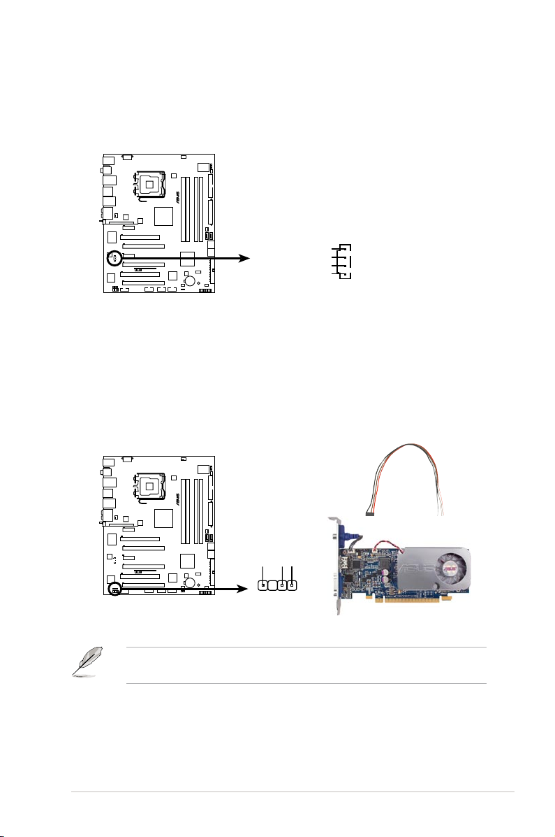
ASUS P5E3 Deluxe/WiFi-AP@n
2-33
10. Optical drive audio connector (4-pin CD)
This connector allows you to receive stereo audio input from sound sources
such as a CD-ROM, TV tuner, or MPEG card.
(black)
11. Digital audio connector (4-1 pin SPDIF, for ASUS HDMI VGA card)
This connector is for an additional Sony/Philips Digital Interface (S/PDIF)
port(s). If you are using ASUS HDMI-equipped graphics card, connect the
HDMI card to this connector with a S/PDIF out cable.
The ASUS HDMI-equipped graphics card and S/PDIF out cable are purchased
separately.
P5E3 DELUXE
®
P5E3 DELUXE/WiFi-AP@n
Internal audio connector
CD
Right Audio Channel
Left Audio Channel
Ground
Ground
P5E3 DELUXE
®
P5E3 DELUXE/WiFi-AP@n
Digital audio connector
+5V
SPDIFOUT
GND
SPDIF_OUT
Page 60

2-34 Chapter 2: Hardware information
•
System power LED (2-pin PLED)
This 2-pin connector is for the system power LED. Connect the chassis
power LED cable to this connector. The system power LED lights up when
you turn on the system power, and blinks when the system is in sleep mode.
•
Hard disk drive activity LED (2-pin IDE_LED)
This 2-pin connector is for the HDD Activity LED. Connect the HDD Activity
LED cable to this connector. The IDE LED lights up or ashes when data is
read from or written to the HDD.
•
System warning speaker (4-pin SPEAKER)
This 4-pin connector is for the chassis-mounted system warning speaker. The
speaker allows you to hear system beeps and warnings.
•
ATX power button/soft-off button (2-pin PWRSW)
This connector is for the system power button. Pressing the power button
turns the system on or puts the system in sleep or soft-off mode depending
on the BIOS settings. Pressing the power switch for more than four seconds
while the system is ON turns the system OFF.
•
Reset button (2-pin RESET)
This 2-pin connector is for the chassis-mounted reset button for system
reboot without turning off the system power.
12. System panel connector (20-8 pin PANEL)
This connector supports several chassis-mounted functions.
P5E3 DELUXE
®
P5E3 DELUXE/WiFi-AP@n
System panel connector
* Requires an ATX power supply.
PANEL
PLED-
PWR
+5V
Speaker
Ground
RESET
Ground
Reset
Ground
Ground
PWRSW
PLED+
IDE_LED-
IDE_LED+
IDE_LED
PLED SPEAKER
Page 61

ASUS P5E3 Deluxe/WiFi-AP@n
2-35
ASUS Q-Connector (system panel)
You can use the ASUS Q-Connector to connect/disconnect chassis front panel
cables in a few steps. Refer to the instructions below to install the ASUS
Q-Connector.
1. Connect the front panel cables to the
ASUS Q-Connector.
Refer to the labels on the Q-Connector
to know the detailed pin denitions, then
match them to the respective front panel
cable labels.
2. Install the ASUS Q-Connector to the
system panel connector, making sure
the orientation matches the labels on the
motherboard.
3. The front panel functions are now enabled.
The gure shows the Q-Connector properly
installed on the motherboard.
Page 62
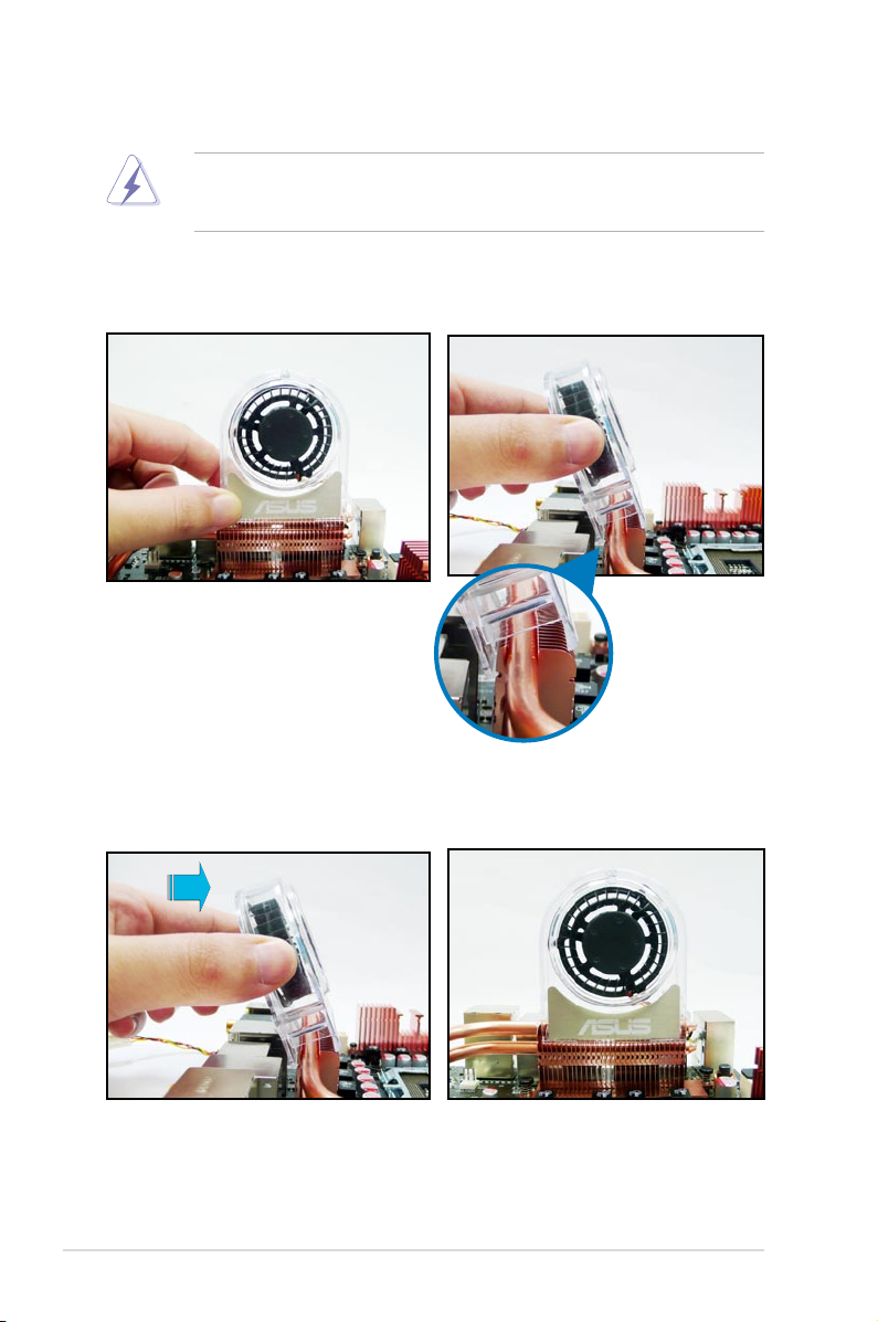
2-36 Chapter 2: Hardware information
2.7.3 Installing the optional fans
Install the optional fan only if you are using a passive cooler or a water cooler.
Installing the optional fan with an active CPU cooler will interfere with the airow
and destabilize the system.
1. Position the fan above the pipe
and heatsink assembly.
2. Fit the fan to the grooved edge of
the heatsink.
3. Carefully push down the fan until
it snugly ts the heatsink, then
connect the fan cable.
4. The photo shows the fan installed
on the motherboard.
Page 63

ASUS P5E3 Deluxe/WiFi-AP@n
2-37
• Plug the optional fan cables to the CHA_FAN1, CHA_FAN2 or PWR_FAN
connector on the motherboard.
•
Make sure the optional fan is installed correctly to prevent damage to the
fan and motherboard components.
5. Follow the previous instructions to install the other optional fan.
6. The photo on the right shows the
fans installed on the motherboard.
Page 64

2-38 Chapter 2: Hardware information
Page 65

3
Powering up
This chapter describes the power up
sequence, the vocal POST messages,
and ways of shutting down the system.
Page 66

ASUS P5E3 Deluxe/WiFi-AP@n
Chapter summary
3
3.1 Starting up for the rst time ........................................................ 3-1
3.2 Turning off the computer .............................................................
3-2
Page 67
ASUS P5E3 Deluxe/WiFi-AP@n 3-1
3.1 Starting up for the rst time
1. After making all the connections, replace the system case cover.
2. Be sure that all switches are off.
3. Connect the power cord to the power connector at the back of the system
chassis.
4. Connect the power cord to a power outlet that is equipped with a surge
protector.
5. Turn on the devices in the following order:
a. Monitor
b. External SCSI devices (starting with the last device on the chain)
c. System power
6. After applying power, the system power LED on the system front panel case
lights up. For systems with ATX power supplies, the system LED lights up
when you press the ATX power button. If your monitor complies with “green”
standards or if it has a “power standby” feature, the monitor LED may light up
or switch between orange and green after the system LED turns on.
The system then runs the power-on self tests or POST. While the tests are
running, the BIOS beeps (see BIOS beep codes table below) or additional
messages appear on the screen. If you do not see anything within 30
seconds from the time you turned on the power, the system may have failed a
power-on test. Check the jumper settings and connections or call your retailer
for assistance.
7. At power on, hold down the <Delete> key to enter the BIOS Setup. Follow the
instructions in Chapter 4.
BIOS Beep Description
One short beep VGA detected
Quick boot set to disabled
No keyboard detected
One continuous beep followed by two
short beeps then a pause (repeated)
No memory detected
One continuous beep followed by three
short beeps
No VGA detected
One continuous beep followed by four
short beeps
Hardware component failure
Page 68

3-2 Chapter 3: Powering up
3.2 Turning off the computer
3.2.1 Using the OS shut down function
If you are using Windows® XP:
1. Click the Start button then select Turn Off Computer.
2. Click the Turn Off button to shut down the computer.
3. The power supply should turn off after Windows
®
shuts down.
If you are using Windows® Vista:
1. Click the Start button then select ShutDown.
2. The power supply should turn off after Windows
®
shuts down.
3.2.2 Using the dual function power switch
While the system is ON, pressing the power switch for less than four seconds puts
the system to sleep mode or to soft-off mode, depending on the BIOS setting.
Pressing the power switch for more than four seconds lets the system enter the
soft-off mode regardless of the BIOS setting. Refer to section
4.6 Power menu
in
Chapter 4 for details.
Page 69

4
BIOS setup
This chapter tells how to change
the system settings through the BIOS
Setup menus. Detailed descriptions
of the BIOS parameters are also
provided.
Page 70

Chapter summary
4
ASUS P5E3 Deluxe/WiFi-AP@n
4.1 Managing and updating your BIOS ............................................ 4-1
4.2
BIOS setup program .................................................................... 4-8
4.3 Main menu .................................................................................. 4-11
4.4 Ai Tweaker ..................................................................................
4-16
4.5 Advanced menu .........................................................................
4-23
4.6 Power menu ................................................................................
4-29
4.7 Boot menu ..................................................................................
4-33
4.8 Tools menu .................................................................................
4-37
4.9 Exit menu ....................................................................................
4-41
Page 71

ASUS P5E3 Deluxe/WiFi-AP@n
4-1
4.1 Managing and updating your BIOS
The following utilities allow you to manage and update the motherboard Basic
Input/Output System (BIOS) setup.
1.
ASUS Update (Updates the BIOS in Windows® environment.)
2.
ASUS EZ Flash 2 (Updates the BIOS using a oppy disk or USB ash disk.)
3.
ASUS AFUDOS (Updates the BIOS using a bootable oppy disk)
4.
ASUS CrashFree BIOS 3 (Updates the BIOS using a bootable oppy disk,
USB ash disk or the motherboard support DVD when the BIOS le fails or
gets corrupted.)
Refer to the corresponding sections for details on these utilities.
Save a copy of the original motherboard BIOS le to a bootable oppy disk or
USB ash disk in case you need to restore the BIOS in the future. Copy the
original motherboard BIOS using the ASUS Update or AFUDOS utilities.
Installing ASUS Update
To install ASUS Update:
1. Place the support DVD in the optical drive. The Drivers menu appears.
2. Click the Utilities tab, then click Install ASUS Update VX.XX.XX.
3. The ASUS Update utility is copied to your system.
4.1.1 ASUS Update utility
The ASUS Update is a utility that allows you to manage, save, and update the
motherboard BIOS in Windows® environment. The ASUS Update utility allows you
to:
• Save the current BIOS le
• Download the latest BIOS le from the Internet
• Update the BIOS from an updated BIOS le
• Update the BIOS directly from the Internet, and
• View the BIOS version information.
This utility is available in the support DVD that comes with the motherboard
package.
ASUS Update requires an Internet connection either through a network or an
Internet Service Provider (ISP).
Page 72

4-2 Chapter 4: BIOS setup
Quit all Windows® applications before you update the BIOS using this utility.
3. Select the ASUS FTP site nearest
you to avoid network trafc, or
click Auto Select. Click Next.
Updating the BIOS through the Internet
To update the BIOS through the Internet:
1. Launch the ASUS Update utility from the Windows
®
desktop by clicking Start
> Programs > ASUS > ASUSUpdate > ASUSUpdate. The ASUS Update
main window appears.
2. Select Update BIOS from the
Internet option from the drop-down
menu, then click Next.
Page 73

ASUS P5E3 Deluxe/WiFi-AP@n
4-3
Updating the BIOS through a BIOS le
To update the BIOS through a BIOS le:
1. Launch the ASUS Update utility from the Windows
®
desktop by clicking Start
> Programs > ASUS > ASUSUpdate > ASUSUpdate. The ASUS Update
main window appears.
2. Select
Update BIOS from a le
option from the drop-down menu,
then click Next.
4. From the FTP site, select the BIOS
version that you wish to download.
Click Next.
5. Follow the screen instructions to
complete the update process.
The ASUS Update utility is
capable of updating itself through
the Internet. Always update the
utility to avail all its features.
3. Locate the BIOS le from the Open
window, then click Open.
4. Follow the screen instructions to
complete the update process.
P5E3D
P5E3D.ROM
Page 74
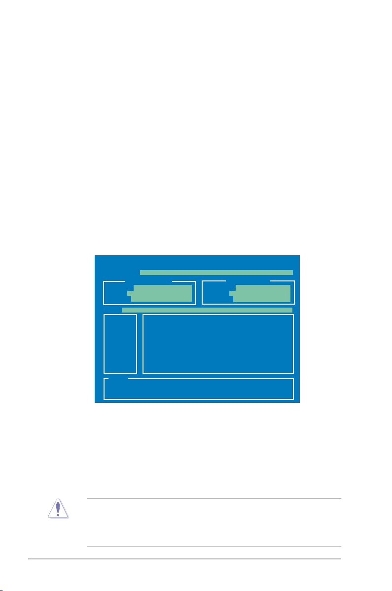
4-4 Chapter 4: BIOS setup
To update the BIOS using EZ Flash 2:
1. Visit the ASUS website (www.asus.com) to download the latest BIOS le for
the motherboard.
2. Save the BIOS le to a oppy disk or a USB ash disk, then restart the
system.
4.1.2 ASUS EZ Flash 2 utility
The ASUS EZ Flash 2 feature allows you to update the BIOS without having to go
through the long process of booting from a oppy disk and using a DOS-based
utility. The EZ Flash 2 utility is built-in the BIOS chip so it is accessible by pressing
<Alt> + <F2> during the Power-On Self Tests (POST).
(2) Enter BIOS setup program. Go to the
Tools menu to select EZ Flash2
and press <Enter> to enable it.
You can switch between drives by pressing <Tab> before the correct le
is found. Then press <Enter>.
3. You can launch the EZ Flash 2 by two methods.
(1)
Insert the oppy disk / USB ash disk that contains the BIOS le to the
oppy disk drive or the USB port.
Press <Alt> + <F2> during POST to display the following.
• This function can support devices such as USB ash disk, or oppy disk
with
FAT 32/16
format and single partition only.
• DO NOT shut down or reset the system while updating the BIOS to prevent
system boot failure!
4. When the correct BIOS le is found, EZ Flash 2 performs the BIOS update
process and automatically reboots the system when done.
ASUSTek EZ Flash 2 BIOS ROM Utility V3.06
Current ROM
Update ROM
A:
Note
[Enter] Select or Load [B] Backup [ESC] Exit
[Tab] Switch [Up/Down/Home/End] Move
FLASH TYPE: SST 25VF016
PATH: A:\
BOARD: P5E3 Deluxe
VER: 0124
DATE: 08/12/07
BOARD: Unknown
VER: Unknown
DATE: Unknown
Page 75

ASUS P5E3 Deluxe/WiFi-AP@n
4-5
4.1.3 AFUDOS utility
The AFUDOS utility allows you to update the BIOS le in DOS environment using
a bootable oppy disk with the updated BIOS le. This utility also allows you to
copy the current BIOS le that you can use as backup when the BIOS fails or gets
corrupted during the updating process.
Copying the current BIOS
To copy the current BIOS le using the AFUDOS utility:
Main lename Extension name
1. Copy the AFUDOS utility (afudos.exe) from the motherboard support DVD to
the bootable oppy disk you created earlier.
2. Boot the system in DOS mode, then at the prompt type:
afudos /o[lename]
where the [lename] is any user-assigned lename not more than eight
alphanumeric characters for the main lename and three alphanumeric
characters for the extension name.
A:\>afudos /oOLDBIOS1.rom
• Make sure that the oppy disk is not write-protected and has at least
1024KB free space to save the le.
• The succeeding BIOS screens are for reference only. The actual BIOS
screen displays may not be same as shown.
The utility returns to the DOS prompt after copying the current BIOS le.
3. Press <Enter>. The utility copies the current BIOS le to the oppy disk.
A:\>afudos /oOLDBIOS1.rom
AMI Firmware Update Utility - Version 1.19(ASUS V2.07(03.11.24BB))
Copyright (C) 2002 American Megatrends, Inc. All rights reserved.
Reading ash ..... done
Write to le...... ok
A:\>
Updating the BIOS le
To update the BIOS le using the AFUDOS utility:
1. Visit the ASUS website (www.asus.com) and download the latest BIOS le for
the motherboard. Save the BIOS le to a bootable oppy disk.
Page 76

4-6 Chapter 4: BIOS setup
2. Copy the AFUDOS utility (afudos.exe) from the motherboard support DVD to
the bootable oppy disk you created earlier.
3. Boot the system in DOS mode, then at the prompt type:
afudos /i[lename]
where [lename] is the latest or the original BIOS le on the bootable oppy
disk.
A:\>afudos /iP5E3D.ROM
Write the BIOS lename on a piece of paper. You need to type the exact BIOS
lename at the DOS prompt.
5. The utility returns to the DOS prompt after the BIOS update process is
completed. Reboot the system from the hard disk drive.
A:\>afudos /iP5E3D.ROM
AMI Firmware Update Utility - Version 1.19(ASUS V2.07(03.11.24BB))
Copyright (C) 2002 American Megatrends, Inc. All rights reserved.
WARNING!! Do not turn off power during ash BIOS
Reading le ....... done
Reading ash ...... done
Advance Check ......
Erasing ash ...... done
Writing ash ...... done
Verifying ash .... done
Please restart your computer
A:\>
A:\>afudos /iP5E3D.ROM
AMI Firmware Update Utility - Version 1.19(ASUS V2.07(03.11.24BB))
Copyright (C) 2002 American Megatrends, Inc. All rights reserved.
WARNING!! Do not turn off power during ash BIOS
Reading le ....... done
Reading ash ...... done
Advance Check ......
Erasing ash ...... done
Writing ash ...... 0x0008CC00 (9%)
4. The utility veries the le and starts updating the BIOS.
DO NOT shut down or reset the system while updating the BIOS to prevent
system boot failure!
Page 77

ASUS P5E3 Deluxe/WiFi-AP@n
4-7
4.1.4 ASUS CrashFree BIOS 3 utility
The ASUS CrashFree BIOS 3 is an auto recovery tool that allows you to restore
the BIOS le when it fails or gets corrupted during the updating process. You can
update a corrupted BIOS le using the motherboard support DVD or the USB ash
disk that contains the updated BIOS le.
• Prepare the motherboard support DVD, the oppy disk or the USB ash
disk containing the updated motherboard BIOS before using this utility.
• If you use a SATA optical drive, always connect the SATA cable to the
SATA1/SATA 2/SATA3/SATA4 connector; otherwise, the utility will not
function.
Recovering the BIOS from the support DVD
To recover the BIOS from the support DVD:
1. Turn on the system.
2. Insert the motherboard support DVD to the optical drive.
3. The utility displays the following message and automatically checks the DVD
for the BIOS le.
4. Restart the system after the utility completes the updating process.
• Only the USB ash disk with FAT 32/16 format and single partition can
support ASUS CrashFree BIOS 3. The device size should be smaller than
8GB.
• DO NOT shut down or reset the system while updating the BIOS! Doing so
can cause system boot failure!
When found, the utility reads the BIOS le and starts ashing the corrupted
BIOS le.
Recovering the BIOS from the USB ash disk
To recover the BIOS from the USB ash disk:
1. Insert the USB ash disk that contains BIOS le to the USB port.
2. Turn on the system.
3. The utility will automatically checks the devices for the BIOS le When found,
the utility reads the BIOS le and starts ashing the corrupted BIOS le.
4. Restart the system after the utility completes the updating process.
Bad BIOS checksum. Starting BIOS recovery...
Checking for oppy...
Bad BIOS checksum. Starting BIOS recovery...
Checking for oppy...
Floppy found!
Reading le “P5K3D.ROM”. Completed.
Start ashing...
Page 78

4-8 Chapter 4: BIOS setup
4.2 BIOS setup program
This motherboard supports a programmable Serial Peripheral Interface (SPI) chip
that you can update using the provided utility described in section 4.1 Managing
and updating your BIOS.
Use the BIOS Setup program when you are installing a motherboard, reconguring
your system, or prompted to “Run Setup.” This section explains how to congure
your system using this utility.
Even if you are not prompted to use the Setup program, you can change the
conguration of your computer in the future. For example, you can enable the
security password feature or change the power management settings. This
requires you to recongure your system using the BIOS Setup program so that the
computer can recognize these changes and record them in the CMOS RAM of the
SPI chip.
The SPI chip on the motherboard stores the Setup utility. When you start up the
computer, the system provides you with the opportunity to run this program. Press
<Del> during the Power-On Self-Test (POST) to enter the Setup utility; otherwise,
POST continues with its test routines.
If you wish to enter Setup after POST, restart the system by pressing
<Ctrl+Alt+Delete>, or by pressing the reset button on the system chassis. You can
also restart by turning the system off and then back on. Do this last option only if
the rst two failed.
The Setup program is designed to make it as easy to use as possible. Being a
menu-driven program, it lets you scroll through the various sub-menus and make
your selections from the available options using the navigation keys.
• The default BIOS settings for this motherboard apply for most conditions
to ensure optimum performance. If the system becomes unstable after
changing any BIOS settings, load the default settings to ensure system
compatibility and stability. Select the Load Setup Defaults item under the
Exit Menu. See section 4.9 Exit Menu.
• The BIOS setup screens shown in this section are for reference purposes
only, and may not exactly match what you see on your screen.
• Visit the ASUS website (www.asus.com) to download the latest BIOS le for
this motherboard.
Page 79

ASUS P5E3 Deluxe/WiFi-AP@n
4-9
Select Screen
Select Item
+-
Change Field
Tab Select Field
F1 General Help
F10 Save and Exit
ESC Exit
v02.61 (C)Copyright 1985-2007, American Megatrends, Inc.
BIOS SETUP UTILITY
Main Ai Tweaker Advanced Power Boot Tools Exit
System Time [10:55:25]
System Date [Mon 07/23/2007]
Legacy Diskette A [1.44M, 3.5 in.]
Language [English]
SATA1 [Not Detected]
SATA2 [Not Detected]
SATA3 [Not Detected]
SATA4 [Not Detected]
SATA5 [Not Detected]
SATA6 [Not Detected]
SATA Conguration
System Information
Use [ENTER], [TAB]
or [SHIFT-TAB] to
select a eld.
Use [+] or [-] to
congure the System
Time.
4.2.2 Menu bar
The menu bar on top of the screen has the following main items:
Main For changing the basic system conguration
Ai Tweaker
For changing the overclocking settings
Advanced For changing the advanced system settings
Power For changing the advanced power management (APM)
conguration
Boot For changing the system boot conguration
Tools For conguring options for special functions
Exit For selecting the exit options and loading default
settings
To select an item on the menu bar, press the right or left arrow key on the keyboard
until the desired item is highlighted.
4.2.3 Navigation keys
At the bottom right corner of a menu screen are the navigation keys for that
particular menu. Use the navigation keys to select items in the menu and change
the settings.
4.2.1 BIOS menu screen
The navigation keys may differ from one screen to another.
Navigation keys
General help
Menu bar
Sub-menu items
Conguration eldsMenu items
Page 80

4-10 Chapter 4: BIOS setup
4.2.4 Menu items
The highlighted item on the menu bar
displays the specic items for that
menu. For example, selecting Main
shows the Main menu items.
The other items (Advanced, Power,
Boot, and Exit) on the menu bar have
their respective menu items.
4.2.5 Sub-menu items
A solid triangle before each item on any menu screen means that the iteam has a
sub-menu. To display the sub-menu, select the item and press <Enter>.
4.2.6 Conguration elds
These elds show the values for the menu items. If an item is user- congurable,
you can change the value of the eld opposite the item. You cannot select an item
that is not user-congurable.
A congurable eld is enclosed in brackets, and is highlighted when selected. To
change the value of a eld, select it then press <Enter> to display a list of options.
Refer to 4.2.7 Pop-up window.
4.2.7 Pop-up window
Select a menu item then press <Enter> to display a pop-up window with the
conguration options for that item.
4.2.8 Scroll bar
A scroll bar appears on the right side of a
menu screen when there are items that do
not t on the screen. Press the
Up/Down arrow keys or <Page Up> /<Page
Down> keys to display the other items on
the screen.
4.2.9 General help
At the top right corner of the menu screen
is a brief description of the selected item.
Main menu items
Scroll bar
Pop-up window
System Time [06:22:54]
System Date [Mon 04/23/2007]
Floppy Diskette A [1.44M, 3.5 in.]
Language [English]
SATA1 [Not Detected]
SATA2 [Not Detected]
SATA3 [Not Detected]
SATA4 [Not Detected]
SATA5 [Not Detected]
SATA6 [Not Detected]
SATA Conguration
System Information
Use [ENTER], [TAB],
or [SHIFT-TAB] to
select a eld.
Use [+] or [-] to
congure system.
Page 81
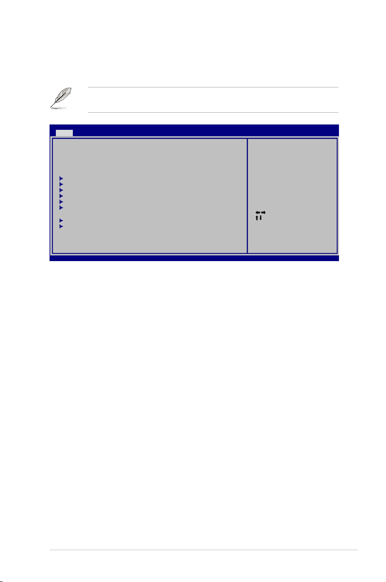
ASUS P5E3 Deluxe/WiFi-AP@n
4-11
4.3 Main menu
When you enter the BIOS Setup program, the Main menu screen appears, giving
you an overview of the basic system information.
4.3.1 System Time [xx:xx:xx]
Allows you to set the system time.
4.3.2 System Date [Day xx/xx/xxxx]
Allows you to set the system date.
4.3.3 Legacy Diskette A [1.44M, 3.5 in.]
Sets the type of oppy drive installed.
Conguration options: [Disabled] [720K , 3.5 in.] [1.44M, 3.5 in.]
4.3.4 Language [English]
Allows you to select the display language for the BIOS setup screen.
Conguration options: [Chinese(BIG5)] [Chinese(GB)] [Japanese] [Français]
[German] [English]
Refer to section 4.2.1 BIOS menu screen for information on the menu screen
items and how to navigate through them.
Select Screen
Select Item
+-
Change Field
Tab Select Field
F1 General Help
F10 Save and Exit
ESC Exit
v02.61 (C)Copyright 1985-2007, American Megatrends, Inc.
BIOS SETUP UTILITY
Main Ai Tweaker Advanced Power Boot Tools Exit
System Time [10:55:25]
System Date [Mon 04/23/2007]
Legacy Diskette A [1.44M, 3.5 in.]
Language [English]
SATA1 [Not Detected]
SATA2 [Not Detected]
SATA3 [Not Detected]
SATA4 [Not Detected]
SATA5 [Not Detected]
SATA6 [Not Detected]
SATA Conguration
System Information
Use [ENTER], [TAB]
or [SHIFT-TAB] to
select a eld.
Use [+] or [-] to
congure the System
Time.
Page 82

4-12 Chapter 4: BIOS setup
4.3.5 SATA 1-6
While entering Setup, the BIOS automatically detects the presence of Serial ATA
devices. There is a separate sub-menu for each SATA device. Select a device item
then press <Enter> to display the SATA device information.
Select Screen
Select Item
+-
Change Option
F1 General Help
F10 Save and Exit
ESC Exit
v02.61 (C)Copyright 1985-2007, American Megatrends, Inc.
BIOS SETUP UTILITY
Main
SATA 1
Device : Hard Disk
Vendor : WDC WD800JD-00LSA0
Size : 80.0GB
LBA Mode : Supported
Block Mode : 16Sectors
PIO Mode : 4
Async DMA : MultiWord DMA-2
Ultra DMA : Ultra DMA-5
SMART Monitoring: Supported
Type [Auto]
LBA/Large Mode [Auto]
Block(Multi-Sector Transfer) [Auto]
PIO Mode [Auto]
DMA Mode [Auto]
SMART Monitoring [Auto]
32Bit Data Transfer [Enabled]
Sel ect t he ty pe of
device connecte d to
the system.
The BIOS automatically detects the values opposite the dimmed items (Device,
Vendor, Size, LBA Mode, Block Mode, PIO Mode, Async DMA, Ultra DMA, and
SMART monitoring). These values are not user-congurable. These items show
N/A if no IDE device is installed in the system.
Type [Auto]
Selects the type of IDE drive. Setting to [Auto] allows automatic selection of the
appropriate IDE device type. Select [CDROM] if you are specically conguring a
CD-ROM drive. Select [ARMD] (ATAPI Removable Media Device) if your device is
either a ZIP, LS-120, or MO drive.
Conguration options: [Not Installed] [Auto] [CDROM] [ARMD]
LBA/Large Mode [Auto]
Enables or disables the LBA mode. Setting to [Auto] enables the LBA mode if the
device supports this mode, and if the device was not previously formatted with LBA
mode disabled. Conguration options: [Disabled] [Auto]
Block (Multi-Sector Transfer) [Auto]
Enables or disables data multi-sectors transfers. When set to [Auto], the data
transfer from and to the device occurs multiple sectors at a time if the device
supports multi-sector transfer feature. When set to [Disabled], the data transfer
from and to the device occurs one sector at a time.
Conguration options: [Disabled] [Auto]
PIO Mode [Auto]
Allows you to select the data transfer mode.
Conguration options: [Auto] [0] [1] [2] [3] [4]
Page 83

ASUS P5E3 Deluxe/WiFi-AP@n
4-13
DMA Mode [Auto]
Selects the DMA mode.
Conguration options: [Auto] [SWDMA0] [SWDMA1] [SWDMA2] [MWDMA0]
[MWDMA1] [MWDMA2] [UDMA0] [UDMA1] [UDMA2] [UDMA3] [UDMA4] [UDMA5]
SMART Monitoring [Auto]
Sets the Smart Monitoring, Analysis, and Reporting Technology.
Conguration options: [Auto] [Disabled] [Enabled]
32Bit Data Transfer [Enabled]
Enables or disables 32-bit data transfer.
Conguration options: [Disabled] [Enabled]
SATA Conguration [Enhanced]
Conguration options: [Disabled] [Compatible] [Enhanced]
Configure SATA as [IDE]
Sets the conguration for the Serial ATA connectors supported by the
Southbridge chip. Conguration options: [IDE] [RAID] [AHCI]
The AHCI allows the onboard storage driver to enable advanced Serial
ATA features that increases storage performance on random workloads by
allowing the drive to internally optimize the order of commands.
If you want to create a RAID 0, RAID 1, RAID 5, RAID 10, or the Intel
®
Matrix
Storage Technology conguration from the Serial ATA hard disk drives, set
this item to [RAID].
If you want to use the Serial ATA hard disk drives as Parallel ATA physical
storage devices, keep the default setting [IDE].
If you want the Serial ATA hard disk drives to use the Advanced Host Controller
Interface (AHCI), set this item to [AHCI].
SATA Conguration
SATA Conguraton [Enhanced]
Congure SATA as [IDE]
Hard Disk Write Protect [Disabled]
SATA Detect Time Out (Sec) [35]
4.3.6 SATA Conguration
The items in this menu allow you to set or change the congurations for the SATA
devices installed in the system. Select an item then press <Enter> if you want to
congure the item.
Options
Disabled
Compatible
Enhanced
Page 84

4-14 Chapter 4: BIOS setup
Hard Disk Write Protect [Disabled]
Disables or enables device write protection. This will be effective only if the device
is accessed through BIOS. Conguration option: [Disabled] [Enabled]
SATA Detect Time Out (Sec) [35]
Selects the time out value for detecting ATA/ATAPI devices.
Conguration options: [0] [5] [10] [15] [20] [25] [30] [35]
SATA Port1 [Auto]
Allows you to select the type of device connected to the system.
Conguration options: [Auto] [Not Installed]
SMART Monitoring [Enabled]
Allows you to set the Self-Monitoring, Analysis and Reporting Technology.
Congration options: [Disabled] [Enabled]
4.3.7 AHCI Conguration
This menu is the section for AHCI conguration. It appears only when you set the
item Congure SATA as from the sub-menu of SATA Conguration to [AHCI].
AHCI Port1~6 [XXXX]
Displays the status of auto-detection of SATA devices.
AHCI Port1
Device :Not Detected
SATA Port1 [Auto]
SMART Monitoring [Enabled]
Select the type of
devices connected to
the system.
AHCI Settings
AHCI CD/DVD Boot Time out [15]
AHCI Port1 [Not Detected]
AHCI Port2 [Not Detected]
AHCI Port3 [Not Detected]
AHCI Port4 [Not Detected]
AHCI Port5 [Not Detected]
AHCI Port6 [Not Detected]
Some SATA CD/DVD in
AHCI mode need to
wait ready longer.
AHCI CD/DVD Boot Time out [15]
Selects the boot time out value for SATA CD/DVD devices in AHCI mode.
Congifuration options: [0] [5] [10] [15] [20] [25] [30] [35]
Page 85

ASUS P5E3 Deluxe/WiFi-AP@n
4-15
4.3.8 System Information
This menu gives you an overview of the general system specications. The BIOS
automatically detects the items in this menu.
ASUS BIOS
Displays the auto-detected BIOS information.
Processor
Displays the auto-detected CPU specication.
System Memory
Displays the auto-detected system memory.
Select Screen
Select Item
F1 General Help
F10 Save and Exit
ESC Exit
v02.61 (C)Copyright 1985-2007, American Megatrends, Inc.
BIOS SETUP UTILITY
Main
ASUS BIOS
Version : 0122
Build Date : 08/05/07
Processor
Type : Genuine Intel(R) CPU 3.20GHz
Speed :3200 MHz
Count : 1
System Memory
Available : 512 MB
Page 86
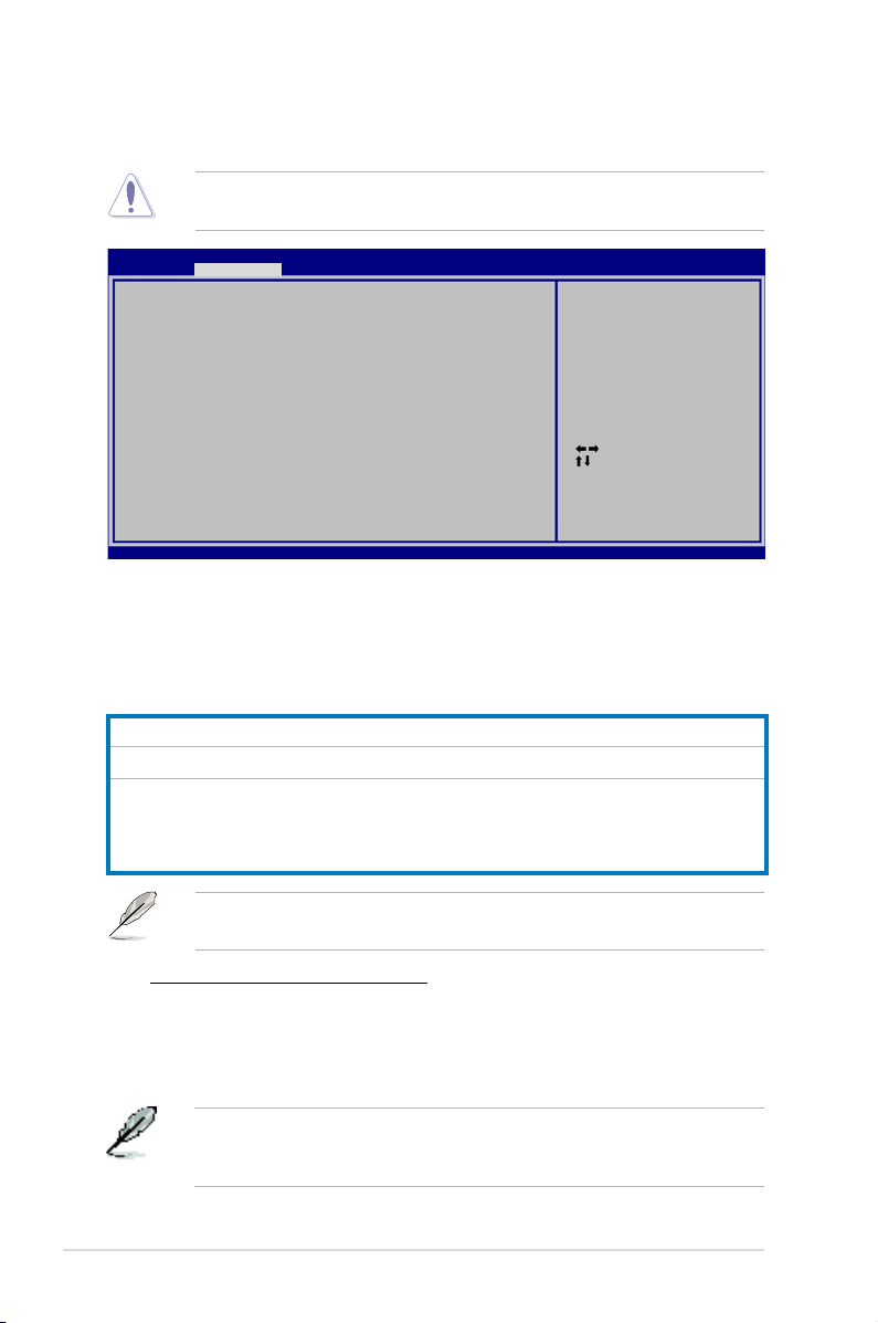
4-16 Chapter 4: BIOS setup
4.4 Ai Tweaker menu
The Ai Tweaker menu items allow you to congure overclocking-related items.
Take caution when changing the settings of the Ai Tweaker menu items.
Incorrect eld values can cause the system to malfunction.
Select Screen
Select Item
Enter Go to Sub Screen
+- Change Option
F1 General Help
F10 Save and Exit
ESC Exit
v02.61 (C)Copyright 1985-2007, American Megatrends, Inc.
BIOS SETUP UTILITY
Main Ai Tweaker Power Boot Tools Exit
Select the target CPU
frequency, and the
relevant parameters
will be auto-adjusted.
Frequencies higher
than CPU manufacturer
recommends are not
guaranteed to be
stable. If the system
becomes unstable,
return to the default.
4.4.1 Ai Overclock Tuner [Auto]
Allows selection of CPU overclocking options to achieve desired CPU internal
frequency. Select either one of the preset overclocking conguration options:
Manual
Allows you to individually set overclocking parameters.
Auto
Loads the optimal settings for the system.
X.M.P.
If you install memory module(s) supporting the eXtreme
Memory Prole (X.M.P.) Technology, choose this item to set the
prole(s) supported by your memory module(s) for optimizing
the system performance.
The conguration options for the following sub-item vary depending on the
DIMMs you install on the motherboard.
eXtreme Memory Profile [Disabled]
This item appears only when you set the Ai Overclock Tuner item to
[X.M.P.]. Allows you to select the X.M.P. mode supported by your Memory
module.
Conguration options: [Disabled] [Prole #1] [Prole #2]
Ai Overclock Tuner [Auto]
CPU Ratio Control [Auto]
FSB Strap to North Bridge [Auto]
DRAM Frequency [Auto]
DRAM Command Rate [Auto]
DRAM Timing Control [Auto]
Pri. Information : 6-6-6-15-4-36-6-4
Sec. Information : 8-4-6-4-7-4-7
DRAM Static Read Control [Auto]
DRAM Dynamic Write Control [Auto]
Ai Clock Twister [Moderate]
Ai Clock Skew for Channel A [Auto]
Ai Clock Skew for Channel B [Auto]
Ai Transaction Booster [Auto]
CPU Spread Spectrum [Auto]
PCIE Spread Spectrum [Auto]
To obtain the best performance of the X.M.P. 1600 DIMM, install only one DIMM
on each memory channel. Refer to the table on the next page for X.M.P. DIMM
installation recommendation.
Page 87

ASUS P5E3 Deluxe/WiFi-AP@n
4-17
FSB Frequency [XXX]
Displays the frequency sent by the clock generator to the system bus and PCI bus.
The value of this item is auto-detected by the BIOS. Use the <+> and <-> keys to
adjust the FSB frequency. You can also type the desired CPU frequency using the
numeric keypad. The values range from 200 to 800. Refer to the table below for
the correct Front Side Bus and CPU External Frequency settings.
4.4.2 CPU Ratio Control [Auto]
Conguration options: [Auto] [Manual].
Ratio CMOS Setting [9]
This sub-item appears only when you set the CPU Ratio Control item to
[Manual]. Allows you to set the ratio between CPU Core Clock and FSB
Frequency. Use the <+> and <-> keys to adjust the ratio. If an invalid ratio is
set in CMOS, then actual and setpoint values may differ.
4.4.3 FSB Strap to North Bridge [Auto]
When set to [Auto], the FSB Strap will be adjusted automatically by FSB
Frequency and DRAM Frequency.
Congifuration options: [Auto] [200MHz] [266MHz] [333MHz]
The following item appears only when you set the Ai Overclock Tuner item to
The following item appears only when you set the Ai Overclock Tuner item to
PCIE Frequency [Auto]
Allows you to set the PCI Express frequency. Use the <+> and <-> keys to adjust
the PCIE frequency. The values range from 100 to 150.
FSB/CPU External Frequency Synchronization
Front Side Bus
FSB 1600 FSB 1333 FSB 1066 FSB 800
CPU External Frequency
400 MHz 333 MHz 266 MHz 200 MHz
X.M.P. DIMM Installation Recommendation
X.M.P. DIMM Frequency
1600 MHz 1600 MHz 1333 MHz 1333 MHz 1333 MHz
Sockets
DIMM_A1
√ - √ - √
DIMM_B1
√ - - √ √
DIMM_A2
- √ √ - √
DIMM_B2
- √ - √ √
Page 88

4-18 Chapter 4: BIOS setup
Pri. Information: 6-6-6-15-4-36-6-4
The values vary depending on your settings of the following sub-items:
CAS# Latency [ 5 DRAM Clocks]
Conguration options: [ 5 DRAM Clocks] [ 6 DRAM Clocks] [ 7 DRAM Clocks]
[ 8 DRAM Clocks] [ 9 DRAM Clocks] [ 10 DRAM Clocks]
RAS# to CAS# Delay [ 5 DRAM Clocks]
Conguration options: [ 3 DRAM Clocks] [ 4 DRAM Clocks]~[ 17 DRAM
Clocks] [18 DRAM Clocks]
RAS# Precharge [ 5 DRAM Clocks]
Conguration options: [ 3 DRAM Clocks] [ 4 DRAM Clocks]~[ 17 DRAM
Clocks] [18 DRAM Clocks]
RAS# Active Time [15 DRAM Clocks]
Conguration options: [ 3 DRAM Clocks] [ 4 DRAM Clocks]~[17 DRAM
Clocks] [18 DRAM Clocks]
RAS# to RAS# Delay [Auto]
Conguration options: [Auto] [ 1 DRAM Clocks]~[15 DRAM Clocks]
4.4.5 DRAM Command Rate [Auto]
Conguration options: [Auto] [1T] [2T]
4.4.6 DRAM Timing Control [Auto]
Conguration options: [Auto] [Manual]
•
The following sub-items apprear only when you set the DRAM Timing
Control item to [Manual].
• The conguration options for some of the following items vary depending
on the DIMMs you install on the motherboard.
The DRAM Frequency conguration options vary with the FSB Frequency
settings.
• Selecting a very high DRAM frequency may cause the system to become
unstable! If this happens, revert to the default setting.
• DDR3-667 help: DRAM frequency lower than 800 MHz may cause system
boot failure due to spec violation.
4.4.4 DRAM Frequency [Auto]
Allows you to set the DDR3 operating frequency.
Conguration options: [Auto] [DDR3-667 MHz] [DDR3-800 MHz] [DDR3-835MHz]
[DDR3-887 MHz] [DDR3-1002MHz] [DDR3-1066MHz] [DDR3-1111] [DDR3-1333]
[DDR3-*1600 MHz*] [DDR3-*1800 MHz*]
Page 89

ASUS P5E3 Deluxe/WiFi-AP@n
4-19
Row Refresh Cycle Time [Auto]
Conguration options: [Auto] [30 DRAM Clocks] [36 DRAM Clocks]
[48 DRAM Clocks] [60 DRAM Clocks] [72 DRAM Clocks]
Write Recovery Time [Auto]
Conguration options: [Auto] [ 1 DRAM Clocks]~[ 15 DRAM Clocks]
Write to Read Delay [Auto]
Conguration options: [Auto] [ 1 DRAM Clocks]~[15 DRAM Clocks]
Read to Precharge Time [Auto]
Conguration options: [Auto] [ 1 DRAM Clocks]~[15 DRAM Clocks]
Sec. Information: 8-4-6-4-7-4-7
The values vary depending on your settings of the following sub-items:
Read to Write Delay(S/D) [Auto]
Conguration options: [Auto] [ 1 DRAM Clocks]~[15 DRAM Clocks]
Write to Read Delay(S) [Auto]
Conguration options: [Auto] [ 1 DRAM Clocks]~[15 DRAM Clocks]
Write to Read Delay(D) [Auto]
Conguration options: [Auto] [ 1 DRAM Clocks]~[15 DRAM Clocks]
Read To Read Delay(S) [Auto]
Conguration options: [Auto] [ 1 DRAM Clocks]~[15 DRAM Clocks]
Read To Read Delay(D) [Auto]
Conguration options: [Auto] [ 1 DRAM Clocks]~[15 DRAM Clocks]
Write To Write Delay(S) [Auto]
Conguration options: [Auto] [ 1 DRAM Clocks]~[15 DRAM Clocks]
Write To Write Delay(D) [Auto]
Conguration options: [Auto] [ 1 DRAM Clocks]~[15 DRAM Clocks]
4.4.7 DRAM Static Read Control [Auto]
Conguration options: [Auto] [Disabled] [Enabled]
4.4.8 DRAM Dynamic Write Control [Auto]
Conguration options: [Auto] [Disabled] [Enabled]
4.4.9 Ai Clock Twister [Auto]
Set this item to [Light] to enhance DRAM compatibility, or [Strong] to enhance
DRAM performance.
Conguration options: [Auto] [Moderate] [Light] [Strong]
Page 90

4-20 Chapter 4: BIOS setup
4.4.10 Ai Clock Skew for Channel A [Auto]
Conguration options: [Auto] [Advance 350ps] [Advance 300ps] [Advance 250ps]
[Advance 200ps] [Advance 150ps] [Advance 100ps] [Advance 50ps] [Normal]
[Delay 50ps] [Delay 100ps] [Delay 150ps] [Delay 200ps] [Delay 250ps] [Delay
300ps] [Delay 350ps]
4.4.11 Ai Clock Skew for Channel B [Auto]
Conguration options: [Auto] [Advance 350ps] [Advance 300ps] [Advance 250ps]
[Advance 200ps] [Advance 150ps] [Advance 100ps] [Advance 50ps] [Normal]
[Delay 50ps] [Delay 100ps] [Delay 150ps] [Delay 200ps] [Delay 250ps] [Delay
300ps] [Delay 350ps]
4.4.12 Ai Transaction Booster [Auto]
Conguration options: [Auto] [Disabled] [Enabled]
Relax Level [1]
This sub-item appears only when you set the Ai Transaction Booster item
to [Disabled]. Set this item to a higher level to get better compatibility. Use the
<+> and <-> keys to adjust the value. The values range from 1 to 8.
Boost Level [1]
This sub-item appears only when you set the Ai Transaction Booster item
to [Enabled]. Set this item to a higher level to get better performance. Use the
<+> and <-> keys to adjust the value. The values range from 1 to 8.
The following seven items appear only when you set the Ai Overclock Tuner
item to [Manual] and [X.M.P.] and are adjusted by typing the desired values
using the numeric keypad and press the <Enter> key. Use the <+> and <-> keys
to adjust the value. To restore the default setting, type [auto] using the keyboard
and press the <Enter> key.
CPU Voltage [Auto]
Allows you to set the CPU VCore voltage. The values range from 1.10000V to
1.70000V with a 0.00625V interval.
Refer to the CPU documentation before setting the CPU Vcore voltage. Setting
a high VCore voltage may damage the CPU permanently, and setting a low
VCore voltage may make the system unstable.
CPU PLL Voltage [Auto]
Allows you to set the CPU PLL voltage. The values range from 1.50V to 2.78V with
a 0.02V interval.
FSB Termination Voltage [Auto]
Allows you to set the front side bus termination voltage. The values range from
1.20V to 2.48V with a 0.02V interval.
Page 91
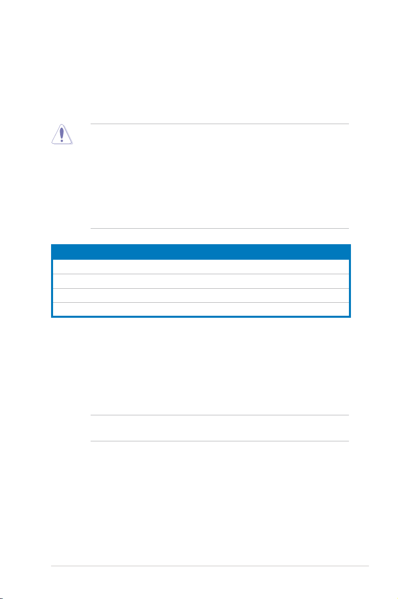
ASUS P5E3 Deluxe/WiFi-AP@n
4-21
DRAM Voltage [Auto]
Allows you to set the DRAM voltage. The values range from 1.50V to 2.78V with a
0.02V interval.
North Bridge Voltage [Auto]
Allows you to set the North Bridge voltage. The values range from 1.25V to 2.53V
with a 0.02V interval.
• Setting the CPU PLL Voltage, FSB Termination Voltage, DRAM Voltage
and North Bridge Voltage to a high level may damage the chipset, memory
module, and CPU permanently. Proceed with caution.
• Some values of the CPU PLL Voltage, FSB Termination Voltage, DRAM
Voltage and North Bridge Voltage items are labeled in different color,
indicating the risk levels of high voltage settings. Refer to the table below
for details.
• The system may need better cooling system to work stably under high
voltage settings.
Blue Yellow Purple Red
CPU PLL Voltage 1.50V~1.78V 1.80V~2.00V 2.02V~2.20V 2.22V~2.78V
FSB Termination Voltage 1.20V~1.38V 1.40V~1.50V N/A N/A
DRAM Voltage 1.50V~1.68V 1.70V~1.90V 1.92V~2.10V 2.12V~2.78V
North Bridge Voltage 1.25V~1.41V 1.43V~1.55V 1.57V~1.73V 1.75V~1.91V
South Bridge Voltage [Auto]
Allows you to set the South Bridge voltage. The values range from 1.05V to 1.20V
with a 0.15V interval.
Clock Over-Charging Voltage [Auto]
Allows you to set the Clock Over-Charging voltage. The values range from 0.70V
to 1.00V with a 0.10V interval.
The following three items appear when you set the Ai Overclock Tuner item to
[Manual] and [X.M.P.].
CPU Voltage Damper [Auto]
Allows you to enable or disable the CPU voltage damper.
Conguration options: [Auto] [Disabled] [Enabled]
CPU Voltage Reference [Auto]
Conguration options: [Auto] [0.63x] [0.61x] [0.59x] [0.57x]
Page 92

4-22 Chapter 4: BIOS setup
North Bridge Voltage Reference [Auto]
Conguration options: [Auto] [0.67x] [0.61x]
4.4.13 CPU Spread Spectrum [Auto]
Allows you to disable or set to auto the CPU clock spread spectrum.
Conguration options: [Auto] [Disabled]
4.4.14 PCIE Spread Spectrum [Auto]
Allows you to disable or set to auto the PCI Express clock spread spectrum.
Conguration options: [Auto] [Disabled]
Page 93

ASUS P5E3 Deluxe/WiFi-AP@n
4-23
4.5 Advanced menu
The Advanced menu items allow you to change the settings for the CPU and other
system devices.
Take caution when changing the settings of the Advanced menu items. Incorrect
eld values can cause the system to malfunction.
Select Screen
Select Item
Enter Go to Sub Screen
F1 General Help
F10 Save and Exit
ESC Exit
v02.61 (C)Copyright 1985-2007, American Megatrends, Inc.
BIOS SETUP UTILITY
Main Ai Tweaker Power Boot Tools Exit
CPU Conguration
Chipset
Onboard Devices Conguration
USB Conguration
PCIPnP
Select Screen
Select Item
+-
Change Option
F1 General Help
F10 Save and Exit
ESC Exit
v02.61 (C)Copyright 1985-2007, American Megatrends, Inc.
BIOS SETUP UTILITY
Advanced
4.5.1 CPU Conguration
The items in this menu show the CPU-related information that the BIOS
automatically detects.
Congure advanced CPU settings
Manufacturer: Intel
Brand String: Intel(R) Core(TM)2 Duo CPU @ 3.00GHz
Frequency : 3.01GHz
FSB Speed : 1333 MHz
Cache L1 : 64 KB
Cache L2 : 4096 KB
CPUID : 6F9
Ratio Status: Unlocked (Max:09, Min:06)
Ratio Actual Value : 9
CPU Ratio Control [Auto]
C1E Support [Enabled]
CPU TM function [Enabled]
Vanderpool Technology [Enabled]
Execute Disable Bit [Enabled]
Max CPUID Value Limit [Disabled]
Intel(R) SpeedStep(TM) Tech. [Enabled]
Options
Auto
Manual
CPU Ratio Control [Auto]
Conguration options: [Auto] [Manual]
The following item appears when the item CPU Ratio Control is set to
[Manual].
Page 94

4-24 Chapter 4: BIOS setup
Ratio CMOS Setting: [9]
Allows you to set the ratio between the CPU Core Clock and the FSB
Frequency. Use <+> and <-> to adjust the value.
Conguration options: [ 6] [ 7] [ 8] [ 9]
C1E Support [Enabled]
Allows you to enable or disable C1E Support.
Conguration options: [Disabled] [Enabled]
CPU TM function [Enabled]
Conguration options: [Disabled] [Enabled]
Vanderpool Technology [Enabled]
Conguration options: [Disabled] [Enabled]
Execute Disable Bit [Enabled]
Allows you to enable or disable the No-Execution Page Protection Technology.
Setting this item to [Disabled] forces the XD feature ag to always return to zero
(0). Conguration options: [Disabled] [Enabled]
Max CPUID Value Limit [Disabled]
Setting this item to [Enabled] allows legacy operating systems to boot even without
support for CPUs with extended CPUID functions.
Conguration options: [Disabled] [Enabled]
The following item appears only when you set the CPU Ratio Control item to
[Auto].
Intel(R) SpeedStep (TM) Tech. [Enabled]
Conguration options: [Disabled] [Enabled]
Page 95

ASUS P5E3 Deluxe/WiFi-AP@n
4-25
BIOS SETUP UTILITY
Advanced
4.5.2 Chipset
The Chipset menu allows you to change the advanced chipset settings. Select an
item then press <Enter> to display the sub-menu.
Advanced Chipset Settings
WARMING: Setting wrong values in below sections
may cause system to malfunction.
North Bridge Conguration
Congure North Bridge
features.
BIOS SETUP UTILITY
Advanced
North Bridge Chipset Conguration
Memory Remap Feature [Enabled]
Initiate Graphic Adapter [PEG/PCI]
PEG Port Control [Auto]
PEG Port Force x1 [Disabled]
North Bridge Chipset Conguration
Memory Remap Feature [Disabled]
Allows you to enable or disable the remapping of the overlapped PCI memory
above the total physical memory. Enable this option only when you install 64-
bit operating system. Conguration options: [Disabled] [Enabled]
Initiate Graphic Adapter [PEG/PCI]
Allows you to decide which graphics controller to use as the primary boot
device. Conguration options: [PCI/PEG] [PEG/PCI]
PEG Port Control [Auto]
Conguration options: [Auto] [Disabled]
Options
Disabled
Enabled
The following item appears only when you set PEG Port Control to [Auto]
PEG Port Force x1 [Disabled]
Conguration options: [Enabled] [Disabled]
Page 96

4-26 Chapter 4: BIOS setup
4.5.3 Onboard Device Conguration
Select Screen
Select Item
+- Change Option
F1 General Help
F10 Save and Exit
ESC Exit
v02.61 (C)Copyright 1985-2007, American Megatrends, Inc.
BIOS SETUP UTILITY
Advanced
Onboard Device Conguration
High Denition Audio [Enabled]
Front Panel Type [HD Audio]
J-Micron eSATA/PATA Controller [Enabled]
Controller Mode [IDE]
Realtek GigaBit LAN [Enabled]
LAN Boot ROM [Disabled]
Marvell GigaBit LAN [Enabled]
LAN Boot ROM [Disabled]
Onboard Wireless LAN [Enabled]
Agere Firewire 1394 [Enabled]
Serial Port1 Address [3F8/IRQ4]
Enable or Disable
High Denition Audio
Controller
High Denition Audio [Enabled]
Allows you to enable or disable the High Denition Audio Controller.
Conguration options: [Enabled] [Disabled]
Front Panel Type [HD Audio]
Allows you to set the front panel audio connector (AAFP) mode to legacy
AC’97 or high-denition audio depending on the audio standard that the front
panel audio module supports. Conguration options: [AC97] [HD Audio]
J-Micron eSATA/PATA Controller [Enabled]
Conguration options: [Enabled] [Disabled]
Controller Mode [IDE]
Conguration options: [RAID] [IDE] [AHCI]
Realtek GigaBit LAN [Enabled]
Conguration options: [Enabled] [Disabled]
LAN Boot ROM [Disabled]
Conguration options: [Disabled] [Enabled]
MarvelI GigaBit LAN [Enabled]
Conguration options: [Enabled] [Disabled]
LAN Boot ROM [Disabled]
Conguration options: [Disabled] [Enabled]
Onboard Wireless LAN [Enabled]
Conguration options: [Enabled] [Disabled]
Agere Firewire 1394 [Enabled]
Conguration options: [Enabled] [Disabled]
Page 97

ASUS P5E3 Deluxe/WiFi-AP@n
4-27
The USB 2.0 Controller Mode item appears only when you enable the USB
2.0 Controller.
USB 2.0 Controller [Enabled]
Allows you to enable or disable the USB 2.0 controller.
Conguration options: [Enabled] [Disabled]
USB 2.0 Controller Mode [HiSpeed]
Allows you to set the USB 2.0 controller mode to HiSpeed (480 Mbps) or
FullSpeed (12 Mbps). Conguration options: [FullSpeed] [HiSpeed]
The following items appear only when you set USB Functions to [Enabled].
4.5.4 USB Conguration
The items in this menu allows you to change the USB-related features. Select an
item then press <Enter> to display the conguration options.
The USB Devices Enabled item shows the auto-detected values. If no USB
device is detected, the item shows None.
Select Screen
Select Item
+-
Change Option
F1 General Help
F10 Save and Exit
ESC Exit
v02.61 (C)Copyright 1985-2007, American Megatrends, Inc.
BIOS SETUP UTILITY
Advanced
USB Conguration
USB Devices Enabled:
None
USB Functions [Enabled]
USB 2.0 Controller [Enabled]
USB 2.0 Controller Mode [HiSpeed]
BIOS EHCI Hand-off [Enabled]
Port 64/60 Emulation [Disabled]
Legacy USB Support [Auto]
USB Functions [Enabled]
Allows you to enable or disable the USB Host Controllers.
Conguration options: [Disabled] [Enabled]
Options
Disabled
Enabled
Serial Port1 Address [3F8/IRQ4]
Allows you to select the Serial Port1 base address.
Conguration options: [Disabled] [3F8/IRQ4] [2F8/IRQ3] [3E8/IRQ4] [2E8/IRQ3]
Page 98
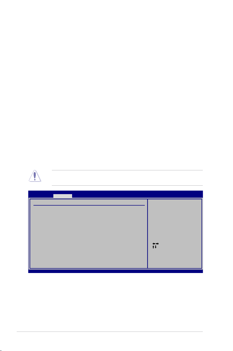
4-28 Chapter 4: BIOS setup
4.5.5 PCIPnP
The PCIPnP menu items allow you to change the advanced settings for PCI/PnP
devices.
Take caution when changing the settings of the PCIPnP menu items. Incorrect
eld values can cause the system to malfunction.
Plug And Play O/S [NO]
When set to [NO], BIOS congures all the devices in the system. When set to
[YES] and if you install a Plug and Play operating system, the operating system
congures the Plug and Play devices not required for boot.
Conguration options: [NO] [YES]
Select Screen
Select Item
+-
Change Option
F1 General Help
F10 Save and Exit
ESC Exit
v02.61 (C)Copyright 1985-2007, American Megatrends, Inc.
BIOS SETUP UTILITY
Advanced
Advanced PCI/PnP Settings
WARNING: Setting wrong values in below sections
may cause system to malfunction.
Plug And Play O/S [NO]
NO: lets the BIOS
congure all the
devices in the system.
YES: lets the operating
system congure Plug
and Play (PnP) devices
not required for boot
if your system has a
Plug and Play operating
system.
BIOS EHCI Hand-off [Enabled]
Allows you to enable the support for operating systems without an EHCI hand-off
feature. Conguration options: [Disabled] [Enabled]
Port 64/60 Emulation [Disabled]
Allows you to enable or disable the I/O port 60h/64h emulation support. This item
should be enabled for the complete USB keyboard legacy support for non-USB
aware OSes. Conguration options: [Disabled] [Enabled]
Legacy USB Support [Auto]
Allows you to enable or disable the support for legacy USB devices. Setting to
[Auto] allows the system to detect the presence of USB devices at startup. If
detected, the USB controller legacy mode is enabled. If no USB device is detected,
the legacy USB support is disabled.
Conguration options: [Disabled] [Enabled] [Auto]
Page 99

ASUS P5E3 Deluxe/WiFi-AP@n
4-29
4.6 Power menu
The Power menu items allow you to change the settings for the Advanced
Power Management (APM). Select an item then press <Enter> to display the
conguration options.
4.6.1 Suspend Mode [Auto]
Allows you to select the Advanced Conguration and Power Interface (ACPI) state
to be used for system suspend.
Conguration options: [S1 (POS) Only] [S3 Only] [Auto]
4.6.2 Repost Video on S3 Resume [Disabled]
Determines whether to invoke VGA BIOS POST on S3/STR resume.
Conguration options: [Disabled] [Enabled]
4.6.3 ACPI 2.0 Support [Disabled]
Add additional tables as per ACPI 2.0 specications.
Conguration options: [Disabled] [Enabled]
4.6.4 ACPI APIC Support [Enabled]
Allows you to enable or disable the Advanced Conguration and Power Interface
(ACPI) support in the Advanced Programmable Interrupt Controller (APIC). When
set to [Enabled], the ACPI APIC table pointer is included in the RSDT pointer list.
Conguration options: [Disabled] [Enabled]
Select Screen
Select Item
+-
Change Option
F1 General Help
F10 Save and Exit
ESC Exit
v02.61 (C)Copyright 1985-2007, American Megatrends, Inc.
BIOS SETUP UTILITY
Main Ai Tweaker Advanced Power Boot Tools Exit
Suspend Mode [Auto]
Repost Video on S3 Resume [Disabled]
ACPI 2.0 Support [Disabled]
ACPI APIC Support [Enabled]
APM Conguration
Hardware Monitor
Select the ACPI state
used for System
Suspend.
Page 100
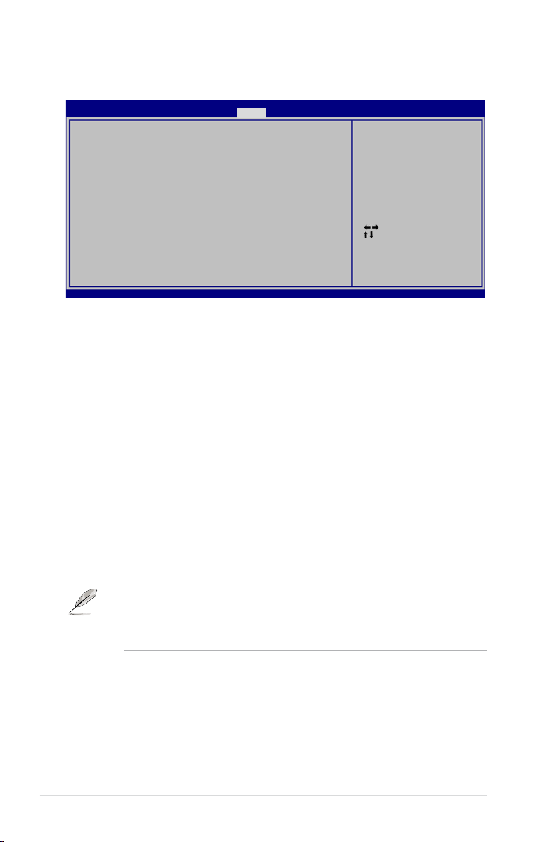
4-30 Chapter 4: BIOS setup
4.6.5 APM Conguration
Restore On AC Power Loss [Power Off]
When set to [Power Off], the system goes into off state after an AC power loss.
When set to [Power On], the system goes on after an AC power loss. When set to
[Last State], the system goes into either off or on state, whatever the system state
was before the AC power loss.
Conguration options: [Power Off] [Power On] [Last State]
Power On By RTC Alarm [Disabled]
Allows you to enable or disable RTC to generate a wake event. When this item
is set to [Enabled], the items RTC Alarm Date/ RTC Alarm Hour/ RTC Alarm
Minute/ RTC Alarm Second will become user-congurable with set values.
Conguration options: [Disabled] [Enabled]
Power On By External Modems [Disabled]
This allows either settings of [Enabled] or [Disabled] for powering up the computer
when the external modem receives a call while the computer is in Soft-off mode.
Conguration options: [Disabled] [Enabled]
The computer cannot receive or transmit data until the computer and
applications are fully running. Thus, connection cannot be made on the rst
try. Turning an external modem off and then back on while the computer is off
causes an initialization string that turns the system power on.
Power On By PCI Devices [Disabled]
Allows you to enable or disable the PME to wake up from S5 by PCI devices.
Conguration options: [Disabled] [Enabled]
Power On By PCIE Devices [Disabled]
Allows you to enable or disable the PCIE devices to generate a wake event.
Conguration options: [Disabled] [Enabled]
Select Screen
Select Item
+-
Change Option
F1 General Help
F10 Save and Exit
ESC Exit
v02.61 (C)Copyright 1985-2007, American Megatrends, Inc.
BIOS SETUP UTILITY
Power
APM Conguration
Restore on AC Power Loss [Power Off]
Power On By RTC Alarm [Disabled]
Power On By External Modems [Disabled]
Power On By PCI Devices [Disabled]
Power On By PCIE Devices [Disabled]
Power On By PS/2 Keyboard [Disabled]
Energy Star 4.0C Support [Disabled]
<Enter> to select
whether or not to
restart the system
after AC power loss.
 Loading...