

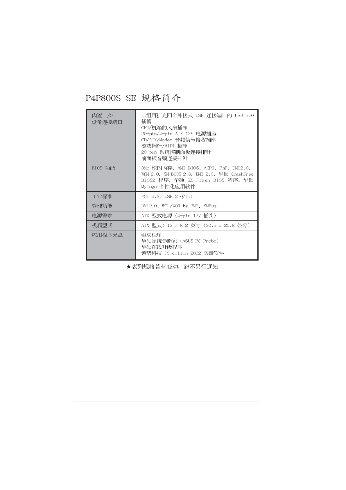
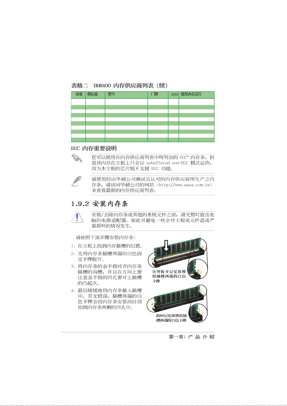
Page 1

P4P800S SE
Motherboard
Page 2
C1483
© 2003
2
Page 3
345
Page 4
Page 5
•
•
•
•
•
•
•
•
•
•
•
•
Page 6
•
•
•
6
Page 7
™
12
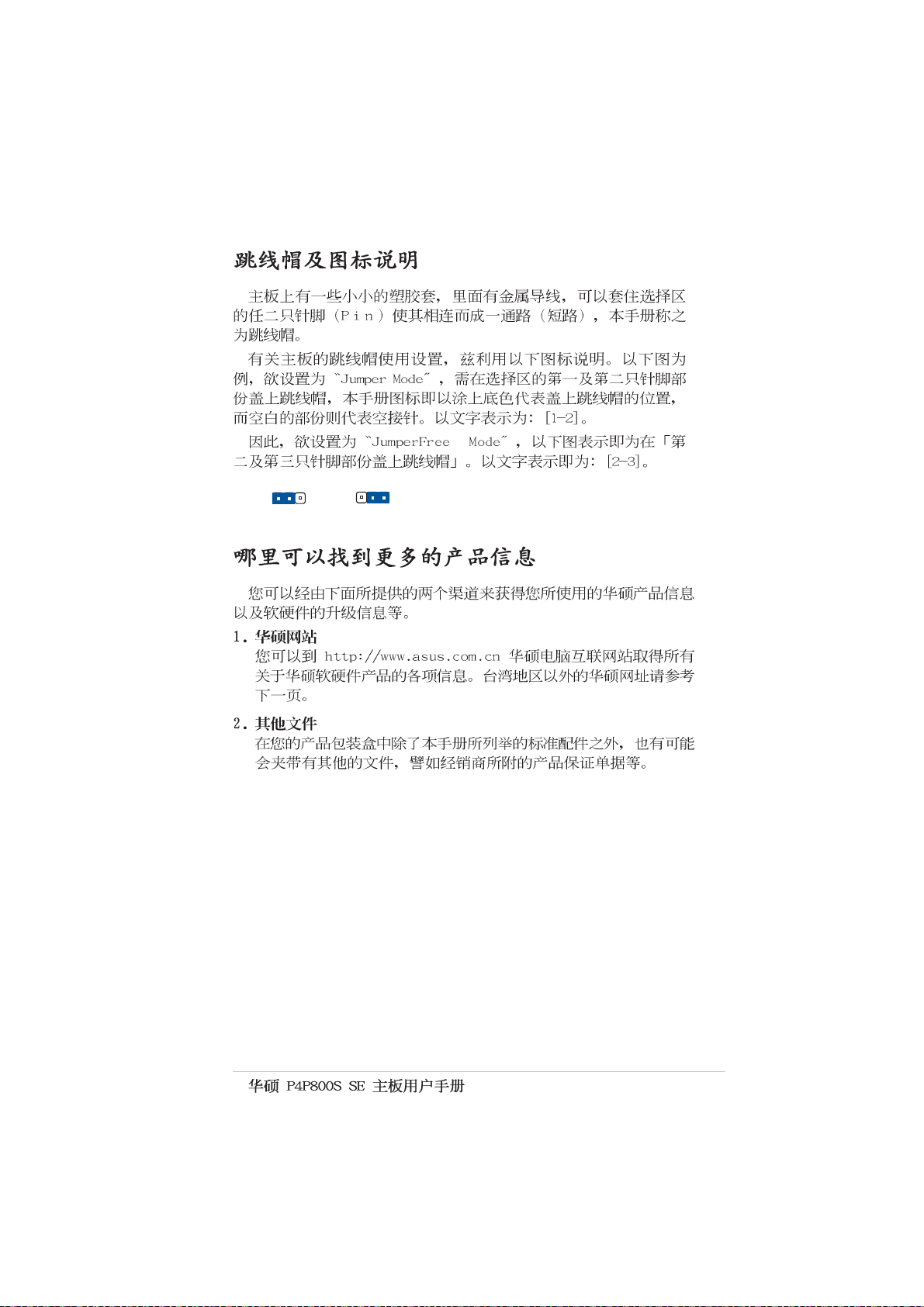
Jumper Mode
23
Jumper Free
(Default)
7
Page 8
8
Page 9
® ®
®
®
®
®
9
Page 10
10
Page 11
1-1
Page 12
®
®
1-2
®
®
Page 13
1-3
Page 14
16
15
14
2
1 7
643 5
8
1-4
13
12
17
27 24
18 19
2526
10
11 9
23
20
21
22
Page 15
®
®
1-5
Page 16
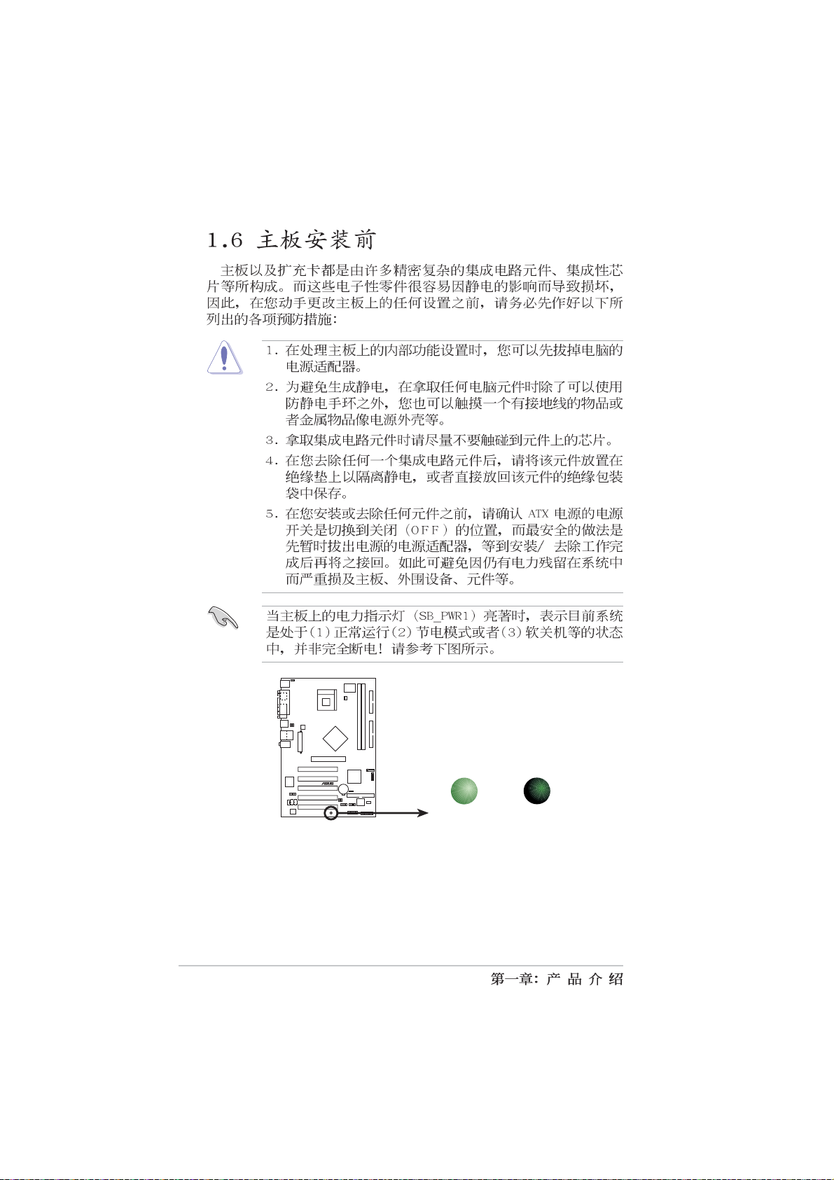
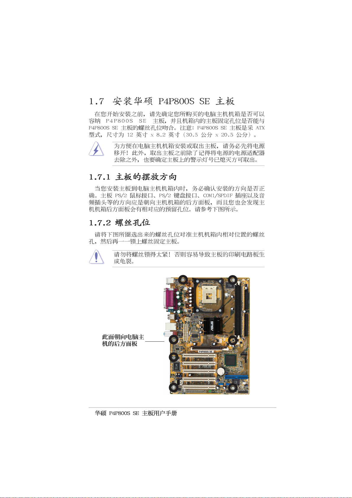
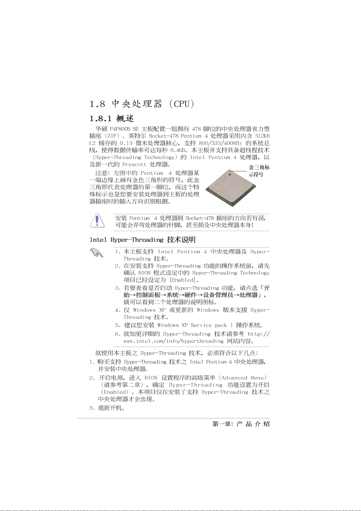
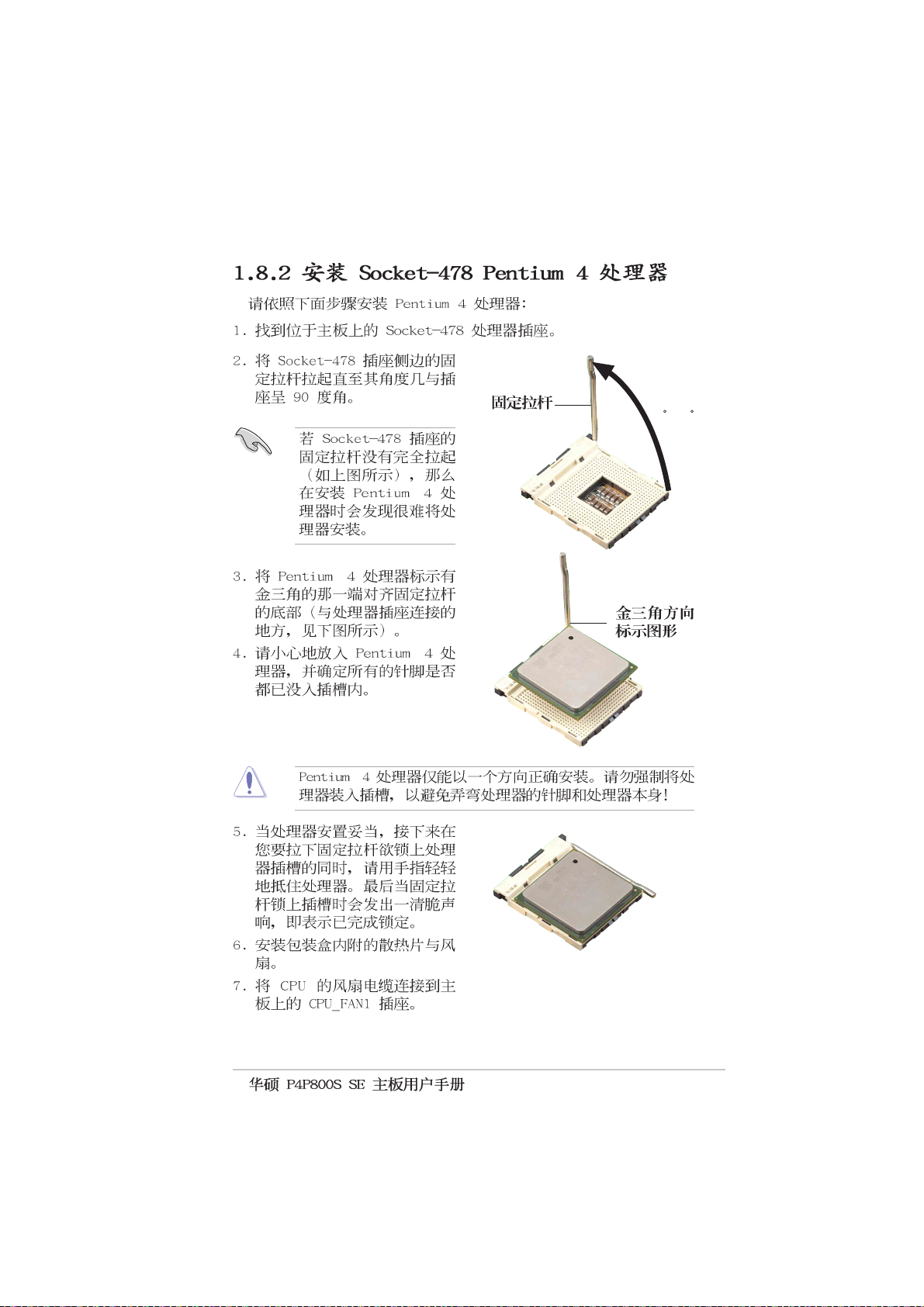
1-6
Page 17
COM1
USBPW12
USBPW34
20.8cm( 8.2in)
KBPWR1
Socket 478
CPU_FAN1
ATX12V1
30.5cm (12.0in)
MODEM1
FP_AUDIO1
CD1
AUX1
P4P800S SE
®
SB_PWR1
USBPW78
USBPW56
USB56
USB78
GAME1
SATA2
SATA1
CLRTC1
CHA_FAN1
CHASSIS1
PANEL1
1-7
Page 18
P4P800S SE
SB_PWR1
®
1-8
P4P800S SE Onboard LED
ON
Standby
Power
OFF
Powered
Off
Page 19
1-9
Page 20
®
® ®
®
®
1-10
Page 21
®
®
90 -100
®
®
®
®
1-11
Page 22
P4P800S SE
®
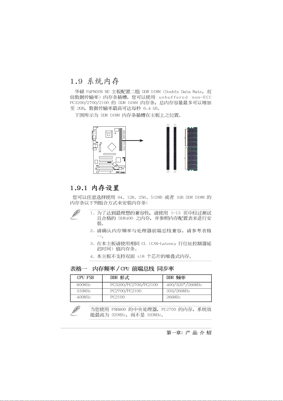
P4P800S SE 184-Pin DDR DIMM Sockets
DIMM1
DIMM2
80 Pins104 Pins
1-12
Page 23
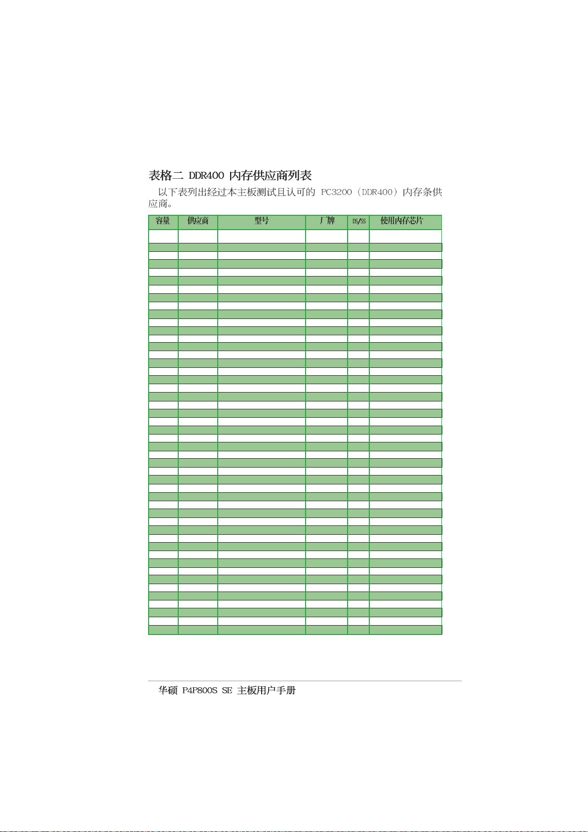
256MB A DATA MDOAD5F3G315B1EC2 A DATA SS ADD8608A8A-5B
256MB A DATA MDOSS6F3G31JB1EAE SAMSUNG SS K4H560838D-TCC4
256MB A DATA MDOWB5F3G316B1EAE Winbond SS W942508BH-5
256MB Apacer 77.10636.465 SAMSUNG SS K4H560838D-TCC4
512MB Apacer 77.10736.464 SAMSUNG DS K4H560838D-TCC4
256MB ATP AG32L64T8SQC4S SAMSUNG SS K4H560838D-TCC4
512MB ATP AG64L64T8SQC4S SAMSUNG DS K4H560838D-TCC4
1024MB ATP AG28L64T8SMC4M MICRON DS MT46V64M4TG-5BC
256MB Brain Power B6U808-256M-SAM-400 SAMSUNG SS K4H560838D-TCC4
512MB Brain Power B6U808-512M-SAM-400 SAMSUNG DS K4H560838D-TCC4
256MB CENTURY DXV6S8SSCCD3K27C SAMSUNG SS K4H560838D-TCCC
512MB CENTURY DXV2S8SSCCD3K27C SAMSUNG DS K4H560838D-TCCC
256MB Hynix HYMD232646B8J-D43 AA Hynix SS HY5DU56822BT-D43
512MB Hynix HYMD264646B8J-D43 AA Hynix DS HY5DU56822BT-D43
128MB Infineon HYB25D256160BT-5B Infineon SS HYS64D16301GU-5-B
256MB Infineon HYS64D32300GU-5-B Infineon SS HYB25D256800BT-5B
512MB Infineon HYS64D64320GU-5-B Infineon DS HYB25D256800BT-5B
256MB KINGSTON KVR400X64C25/256 Winbond SS W942508BH-5
256MB KINGSTON KVR400X64C3A/256 hynix SS HY5DU56822BT-D43
512MB KINGSTON KVR400X64C3A/512 hynix DS HY5DU56822BT-D43
256MB MICRON MT8VDDT3264AG-40BC4 MICRON SS MT46V32M8TG-5BC
512MB MICRON MT16VDDT6464AG-40BC4 MICRON DS MT46V32M8TG-5BC
256MB MICRON MT16VDDT3264AG-403B2 MICRON DS MT46V16M8-5TESB
128MB NANYA NT128D64SH4B1G-5T NANYA SS NT5DS16M16BT-5T
256MB NANYA NT256D64S88B1G-5T NANYA SS NT5DS32M8BT-5T
512MB NANYA N512D64S8HB1G-5T NANYA DS NT5DS32M8BT-5T
512MB PSC AL6D8A53T1-5B PSC DS A2S56D30ATP
256MB SAMSUNG M368L3223ETM-CCC SAMSUNG SS K4H560838E-TCCC
512MB SAMSUNG M368L6432ETM-CCC SAMSUNG DS K4H560838E-TCCC
256MB Transcend TS32MLD64V4F3 SAMSUNG SS K4H560838D-TCCC
256MB Transcend TS32MLD64V4F3 MOSEL SS V58C2256804SAT5
512MB Transcend TS64MLD64V4F3 Hynix DS HY5DU56822BT-D43
512MB Transcend TS64MLD64V4F3 SAMSUNG DS K4H560838D-TCCC
512MB Transcend TS64MLD64V4F3 MOSEL DS V58C2256804SAT5
256MB TwinMos M2G9I08AFATT9F081AA4T TwinMos SS TMD7608F8E50D
512MB TwinMos M2G9J16AGATT9F081AA4T TwinMos DS TMD7608F8E50D
256MB TwinMos M2S9I08AFAPS9F0811A-T PSC SS A2S56D30ATP
256MB TwinMos M2G9I08AFTT9F0811DDT TwinMos SS TMD7608F8E50B
512MB TwinMos M2G9J16AJATT9F0811DDT TwinMos DS TMD7608F8E50B
256MB Winbond W9425GCDB-5 Winbond SS W942508CH-5
512MB Winbond W9451GCDB-5 Winbond DS W942508CH-5
256MB A DATA MDOAD5F3G31YB1EZ2 A DATA SS ADD8608A8A-5B
256MB OCZ PC3500 N/A SS X4W560840A-40
256MB GEIL PC3500 N/A DS N/A
512MB GEIL GL3LC32G88TG N/A DS N/A
256MB CORSAIR CMX256A-3500C2PT N/A DS N/A
256MB CORSAIR CMX256A-3500C2 XMS3502V1.1 N/A DS N/A
512MB CORSAIR CMX512A-3500C2 XMS3502V1.1 N/A DS N/A
1-13
Page 24
256MB KINGSTON KVR400X72C25/256 Winbond SS W942508BH-5(ECC)*
512MB KINGSTON KVR400X72C25/512 Winbond DS W942508BH-5(ECC)*
256MB SAMSUNG M381L3223ETM-CCC SAMSUNG SS K4H560838E-TCCC(ECC)*
512MB SAMSUNG M381L6423ETM-CCC SAMSUNG DS K4H560838E-TCCC(ECC)*
256MB ATP AG32L72T8SQC4S SAMSUNG SS K4H560838D-TCC4(ECC)*
512MB ATP AG64L72T8SQC4S SAMSUNG DS K4H560838D-TCC4(ECC)*
256MB KINGSTON KVR400X72C3A/256 MOSEL SS V58C2256804SAT5(ECC)*
512MB KINGSTON KVR400X72C3A/512 MOSEL DS V58C2256804SAT5(ECC)*
256MB KINGMAX MPXB62D-38KT3R KINGMAX SS KDL388P4EA-50
512MB KINGMAX MPXC22D-38KT3R KINGMAX DS KDL388P4EA-50(A)
1-14
Page 25

ABCDEFGH
1-15
Page 26

1-16
P4P800S SE
®
Keyed for 1.5v
P4P800S SE Accelerated Graphics Port (AGP)
Page 27

P4P800S SE
®
P4P800S SE Clear RTC RAM
CLRTC1
12 23
Normal Clear CMOS
(Default)
1-17
Page 28

USBPW12
USBPW34
21
2
3
P4P800S SE
®
P4P800S SE USB Device Wake Up
P4P800S SE
®
+5V
(Default)
USBPW78
USBPW56
21
+5V
(Default)
KBPWR1
+5V +5VSB
(Default)
+5VSB
2
+5VSB
2312
3
1-18
P4P800S SE Keyboard Power Setting
Page 29

FLOPPY1
P4P800S SE
®
PIN 1
P4P800S SE Floppy Disk Drive Connector
+12.0VDC
+5VSB
PWR_OK
P4P800S SE
®
+5.0VDC
+5.0VDC
+3.3VDC
+3.3VDC
P4P800S SE ATX Power Connectors
ATXPWR1
Pin 1
COM
COM
COM
+5.0VDC
+5.0VDC
-5.0VDC
COM
COM
COM
PS_ON#
COM
-12.0VDC
+3.3VDC
ATX12V1
+12V DC GND
+12V DC GND
1-19
Page 30

GND
RSATA_TXP2
GND
GND
RSATA_TXN2
RSATA_RXN2
RSATA_RXP2
P4P800S SE
SATA2
®
P4P800S SE SATA Connectors
•
•
•
SATA1
GND
RSATA_TXP1
RSATA_TXN1
GND
RSATA_RXN1
RSATA_RXP1
GND
1-20
Page 31

1-21
Page 32

1-22
P4P800S SE
®
P4P800S SE IDE Connectors
PRI_IDE1
PIN 1
SEC_IDE1
PIN 1
Page 33

P4P800S SE
®
P4P800S SE Chassis Alarm Lead
CHASSIS1
CPU_FAN1
GND
+12V
Rotation
+5VSB_MB
Chassis Signal
GND
(Default)
P4P800S SE
®
CHA_FAN1
P4P800S SE 12-Volt Fan Connectors
GND
+12V
Rotation
1-23
Page 34

P4P800S SE
®
MODEM1
Modem-In
Ground
Ground
Modem-Out
P4P800S SE Internal Audio Connectors
P4P800S SE
®
USB56
P4P800S SE USB 2.0 Header
Right Audio Channel
Ground
Ground
Left Audio Channel
CD1(Black) AUX1(White)
USB+5V
USB_P6-
USB_P6+
GND
NC
USB+5V
USB_P5-
USB_P5+
USB78
GND
1
1
USB+5V
USB_P8-
USB_P8+
USB+5V
USB_P7-
USB_P7+
GND
GND
NC
1-24
Page 35

P4P800S SE
®
P4P800S SE Front Panel Audio Connector
P4P800S SE
®
P4P800S SE Game Connector
FP_AUDIO1
GAME1
+5V
J1B2
MIDI_IN
J1CY
J2B2
GND
J2CY
AGND
MIC2
GND
J1CX
J1B1
+5V
+5V
J2B1
J2CX
MIDI_OUT
+5VA
BLINE_OUT_R
NC
MICPWR
Line out_R
BLINE_OUT_L
Line out_L
1-25
Page 36

Speaker
PLED-
IDE_LED-
Connector
Ground
Speaker
Ground
+5V
PWR
Reset
Ground
Ground
Reset SW
ATX Power
Switch*
P4P800S SE
Power LED
PLED+
®
IDE_LED+
IDE_LED
*
Requires an ATX power supply.
P4P800S SE System Panel Connector
•
•
•
1-26
•
•
Page 37

2-1
Page 38

2-2
Page 39

A:\>afudos /iP4P800SS.rom
AMI Firmware Update Utility - Version 1.10
Copyright (C) 2002 American Megatrends, Inc. All rights reserved.
Reading file ..... done
Erasing flash .... done
Writing flash .... 0x0008CC00 (9%)
A:\>afudos /iP4P800SS.rom
AMI Firmware Update Utility - Version 1.10
Copyright (C) 2002 American Megatrends, Inc. All rights reserved.
Reading file ..... done
Erasing flash .... done
Writing flash .... 0x0008CC00 (9%)
Verifying flash .. done
A:\>
2-3
Page 40

A:\>afudos /oMYBIOS03.rom
AMI Firmware Update Utility - Version 1.10
Copyright (C) 2002 American Megatrends, Inc. All rights reserved.
Reading flash ..... 0x0008CC00 (9%)
A:\>afudos /oMYBIOS03.rom
AMI Firmware Update Utility - Version 1.10
Copyright (C) 2002 American Megatrends, Inc. All rights reserved.
Reading flash ..... done
A:\>
2-4
Page 41

User recovery requested. Starting BIOS recovery...
Checking for floppy...
•
•
User recovery requested. Starting BIOS recovery...
Checking for floppy...
Floppy found!
Reading file “P4P800SS.rom”. Completed.
Start flashing...
Flashed successfully. Rebooting.
2-5
Page 42

Bad BIOS checksum. Starting BIOS recovery...
Checking for floppy...
Bad BIOS checksum. Starting BIOS recovery...
Checking for floppy...
Floppy found!
Reading file “P4P800SS.rom”. Completed.
Start flashing...
2-6
Page 43

Bad BIOS checksum. Starting BIOS recovery...
Checking for floppy...
Bad BIOS checksum. Starting BIOS recovery...
Checking for floppy...
Floppy not found!
Checking for CD-ROM...
CD-ROM found.
Reading file “P4P800S SE.rom”. Completed.
Start flashing...
2-7
Page 44

2-8
Page 45

System Time [11:10:19]
System Date [Thu 03/27/2003]
Legacy Diskette A [1.44M, 3.5 in]
Primary IDE Master :[ST320413A]
Primary IDE Slave :[ASUS CD-S340]
Secondary IDE Master :[Not Detected]
Secondary IDE Slave :[Not Detected]
Third IDE Master :[Not Detected]
Fourth IDE Master :[Not Detected]
IDE Configuration
System Information
Use [ENTER], [TAB]
or [SHIFT-TAB] to
select a field.
Use [+] or [-] to
configure system time.
Select Screen
Select Item
+- Change Field
Tab Select Field
F1 General Help
F10 Save and Exit
ESC Exit
2-9
Page 46

System Time [11:10:19]
System Date [Thu 03/27/2003]
Legacy Diskette A [1.44M, 3.5 in]
Primary IDE Master :[ST320413A]
Primary IDE Slave :[ASUS CD-S340]
Secondary IDE Master :[Not Detected]
Secondary IDE Slave :[Not Detected]
Third IDE Master :[Not Detected]
Fourth IDE Master :[Not Detected]
IDE Configuration
System Information
Advanced Chipset settings
WARNING: Setting wrong values in the sections below
may cause system to malfunction.
Configure DRAM Timing by SPD [Enabled]
Memory Acceleration Mode [Auto]
DRAM Idle Timer [Auto]
DRAm Refresh Rate [Auto]
Graphic Adapter Priority [AGP/PCI]
Graphics Aperture Size [ 64 MB]
Spread Spectrum [Enabled]
ICH Delayed Transaction [Enabled]
MPS Revision [1.4]
Use [ENTER], [TAB]
or [SHIFT-TAB] to
select a field.
Use [+] or [-] to
configure system time.
Select Screen
Select Item
+- Change Field
Tab Select Field
F1 General Help
F10 Save and Exit
ESC Exit
Select Screen
Select Item
+- Change Option
F1 General Help
F10 Save and Exit
ESC Exit
2-10
Page 47

System Time [11:10:19]
System Date [Thu 03/27/2003]
Legacy Diskette A [1.44M, 3.5 in]
Primary IDE Master :[ST320413A]
Primary IDE Slave :[ASUS CD-S340]
Secondary IDE Master :[Not Detected]
Secondary IDE Slave :[Not Detected]
Third IDE Master :[Not Detected]
Fourth IDE Master :[Not Detected]
IDE Configuration
System Information
Use [ENTER], [TAB]
or [SHIFT-TAB] to
select a field.
Use [+] or [-] to
configure system time.
Select Screen
Select Item
+- Change Field
Tab Select Field
F1 General Help
F10 Save and Exit
ESC Exit
2-11
Page 48

Primary IDE Master
Device : Hard Disk
Vendor : ST320413A
Size : 20.0GB
LBA Mode : Supported
Block Mode : 16 Sectors
PIO Mode : Supported
Async DMA : MultiWord DMA-2
Ultra DMA : Ultra DMA-5
SMART Monitoring: Supported
Type
LBA/Large Mode
Block (Multi-sector Transfer)
PIO Mode
DMA Mode
Smart Monitoring
32Bit Data Transfer
[Auto]
[Auto]
[Auto]
[Auto]
[Auto]
[Auto]
[Disabled]
Select the type
of device connected
to the system.
Select Screen
Select Item
+- Change Option
F1 General Help
F10 Save and Exit
ESC Exit
2-12
Page 49

IDE Configuration
Onboard IDE Operate Mode [Enhanced Mode]
Enhanced Mode Support On [P-ATA]
IDE Detect Time Out (Sec) [35]
Select Screen
Select Item
+- Change Option
F1 General Help
F10 Save and Exit
ESC Exit
2-13
Page 50

2-14
Page 51

AMI BIOS
Version : 08.00.08
Build Date : 08/01/03
Processor
Type : Intel(R) Pentium(R) 4 CPU 1.73GHz
Speed : 1733 MHz
Count : 1
System Memory
Size : 256MB
Select Screen
Select Item
+- Change Option
F1 General Help
F10 Save and Exit
ESC Exit
JumperFree Configuration
CPU Configuration
Chipset
Onboard Devices Configuration
PCI PnP
USB Configuration
Instant Music Configuration
Configure CPU.
Select Screen
Select Item
Enter Go to Sub-screen
F1 General Help
F10 Save and Exit
ESC Exit
2-15
Page 52

Configure System Frequency/Voltage
AI Overclock Tuner [Standard]
Performance Mode [Auto]
Select Screen
Select Item
+- Change Option
F1 General Help
F10 Save and Exit
ESC Exit
2-16
Page 53

Configure System Frequency/Voltage
AI Overclock Tuner [Manual]
CPU External Frequency (MHz) [100]
DRAM Frequency [Auto]
AGP/PCI Frequency (MHz) [Auto]
CPU VCore Voltage [Auto]
DDR Reference Voltage [Auto]
AGP VDDQ Voltage [Auto]
Performance Mode [Auto]
Select Screen
Select Item
+- Change Option
F1 General Help
F10 Save and Exit
ESC Exit
2-17
Page 54

Configure advanced CPU settings
Manufacturer : Intel(R)
Brand String : Intel(R) Pentium(R) 4 CPU 1.73GHz
Frequency : 1733 MHz
Ratio Status : Locked
Ratio Actual Value : 13
CPUID Maximum Value Limit [Disabled]
Hyper Threading Technology [Enabled]
Select Screen
Select Item
+- Change Option
F1 General Help
F10 Save and Exit
ESC Exit
Advanced Chipset settings
WARNING: Setting wrong values in the sections below
may cause system to malfunction.
Configure DRAM Timing by SPD [Enabled]
Memory Acceleration Mode [Auto]
DRAM Idle Timer [Auto]
DRAm Refresh Rate [Auto]
Graphic Adapter Priority [AGP/PCI]
Graphics Aperture Size [ 64 MB]
Spread Spectrum [Enabled]
ICH Delayed Transaction [Enabled]
MPS Revision [1.4]
2-18
Select Screen
Select Item
+- Change Option
F1 General Help
F10 Save and Exit
ESC Exit
Page 55

2-19
Page 56

OnBoard AC’97 Audio [Auto]
OnBoard LAN [Enabled]
OnBoard LAN Boot ROM [Disabled]
Serial Port1 Address [3F8/IRQ4]
Parallel Port Address [378]
Parallel Port Mode [ECP]
ECP Mode DMA Channel [DMA3]
Parallel Port IRQ [IRQ7]
OnBoard Game/MIDI Port [Disabled]
2-20
Select Screen
Select Item
+- Change Option
F1 General Help
F10 Save and Exit
ESC Exit
Page 57

2-21
Page 58

Advanced PCI/PnP settings
WARNING: Setting wrong values in the sections below
may cause system to malfunction.
Plug and Play OS [No]
PCI Latency Timer [64]
Allocate IRQ to PCI VGA [Yes]
Palette Snooping [Disabled]
PCI IDE BusMaster [Enabled]
IRQ3 [Available]
IRQ4 [Available]
IRQ5 [Available]
IRQ7 [Available]
IRQ9 [Available]
IRQ10 [Available]
IRQ11 [Available]
IRQ14 [Available]
IRQ15 [Available]
NO: Lets the bIOS
configure all the
devices in the system.
YES: Lets the
operating system
configure Plug and
Play (PnP) devices not
required for boot if
your system has a Plug
and Play operating
system.
Select Screen
Select Item
+- Change Option
F1 General Help
F10 Save and Exit
ESC Exit
2-22
Page 59

USB Configuration
Module Version : 2.22.4-5.3
USB Devices Enabled : None
USB Function [8 USB Ports]
Legacy USB Support [Auto]
USB 2.0 Controller [Enabled]
USB 2.0 Controller Mode [HiSpeed]
USB Mass Storage Device Configuration
Enables USB host
controllers.
Select Screen
Select Item
+- Change Option
F1 General Help
F10 Save and Exit
ESC Exit
2-23
Page 60

USB Mass Storage Device Configuration
USB Mass Storage Reset Delay [20 Sec]
No USB Mass Storage device detected
Device #1 N/A
Emulation Type [N/A]
Device #2 N/A
Emulation Type [N/A]
Device #3 N/A
Emulation Type [N/A]
Device #4 N/A
Emulation Type [N/A]
Device #5 N/A
Emulation Type [N/A]
Device #6 N/A
Emulation Type [N/A]
Number of seconds
POST waits for the USB
mass storage device
after that start unit
command.
Select Screen
Select Item
+- Change Option
F1 General Help
F10 Save and Exit
ESC Exit
2-24
Page 61

Instant Music Option
Instant Music [Disabled]
Disable/Enable Instant
Music feature.
Select Screen
Select Item
+- Change Option
F1 General Help
F10 Save and Exit
ESC Exit
2-25
Page 62

Suspend Mode [Auto]
Repost Video on S3 Resume [No]
ACPI 2.0 Support [No]
ACPI APIC Support [Enabled]
BIOS -> AML ACPI table [Enabled]
APM Configuration
Hardware Monitor
Configure CPU.
Select Screen
Select Item
Enter Go to Sub-screen
F1 General Help
F10 Save and Exit
ESC Exit
2-26
Page 63

APM Configuration
Power Management/APM [Enabled]
Video Power Down Mode [Suspend]
Hard Disk Power Down Mode [Suspend]
Suspend Time Out [Disabled]
Throttle Slow Clock Ratio [50%]
System Thermal [Disabled]
Power Button Mode [On/Off]
Restore on AC Power Loss [Power Off]
Power On By RTC Alarm [Disabled]
Power On By External Modem [Disabled]
Power On By PCI Devices [Disabled]
Power On By PS/2 Keyboard [Disabled]
Power On By PS/2 Mouse [Disabled]
Enabled or disable
APM.
Select Screen
Select Item
+- Change Option
F1 General Help
F10 Save and Exit
ESC Exit
2-27
Page 64

2-28
Page 65

Hardware Monitor
CPU Temperature [44°C/111°F]
MB Temperature [36°C/96.5°F]
CPU Fan Speed [2250RPM]
Chassis Fan Speed [XXX RPM]
VCORE Voltage [1.550V]
3.3V Voltage [3.386V]
5V Voltage [4.890V]
12V Voltage [11.900V]
CPU temperature
Select Screen
Select Item
+- Change Option
F1 General Help
F10 Save and Exit
ESC Exit
2-29
Page 66

Boot Settings
Boot Device Priority
Removable Drives
Boot Settings Configuration
Security
Specifies the Boot
Device Priority
sequence.
Select Screen
Select Item
Enter Go to Sub-screen
F1 General Help
F10 Save and Exit
ESC Exit
Boot Device Priority
1st Boot Device [1st FLOPPY DRIV]
2nd Boot Device [PM-ST320413A]
3rd Boot Device [PS-ASUS CD-S340]
Specifies the boot
sequence from the
available devices.
A device enclosed in
parenthesis has been
disabled in the
corresponding type
menu.
Select Screen
Select Item
+- Change Option
F1 General Help
F10 Save and Exit
ESC Exit
2-30
Page 67

Removable Drives
1st Drive [1st FLOPPY DRIVE]
2nd Drive [PM-ST320413A]
3rd Drive [PS-ASUS CD-S340]
Specifies the boot
sequence from the
available devices.
A device enclosed in
parenthesis has been
disabled in the
corresponding type
menu.
Select Screen
Select Item
+- Change Option
F1 General Help
F10 Save and Exit
ESC Exit
Boot Settings Configuration
Quick Boot [Enabled]
Full Screen Logo [Enabled]
Add On ROM Display Mode [Force BIOS]
Bootup Num-Lock [On]
PS/2 Mouse Support [Auto]
Typematic Rate [Fast]
Boot to OS/2 [No]
Wait for ‘F1’ If Error [Enabled]
Hit ‘DEL’ Message Display [Enabled]
Interrupt 19 Capture [Disabled]
Allows BIOS to skip
certain tests while
booting. This will
decrease the time
needed to boot the
system.
Select Screen
Select Item
+- Change Option
F1 General Help
F10 Save and Exit
ESC Exit
2-31
Page 68

2-32
Page 69

Security Settings
Supervisor Password :Installed
User Password :Installed
Change Supervisor Password
User Access Level [Full Access]
Change User Password
Clear User Password
Password Check [Setup]
Boot Sector Virus Protection [Disabled]
<Enter> to change
password.
<Enter> again to
disable password.
Select Screen
Select Item
+- Change Option
F1 General Help
F10 Save and Exit
ESC Exit
2-33
Page 70

Security Settings
Supervisor Password Installed
User Password Not Installed
Change Supervisor Password
User Access Level [Full Access]
Change User Password
Clear User Password
Password Check [Setup]
Boot Sector Virus Protection [Disabled]
<Enter> to change
password.
<Enter> again to
disable password.
Select Screen
Select Item
+- Change Option
F1 General Help
F10 Save and Exit
ESC Exit
2-34
Page 71

Exit Options
Exit & Save Changes
Exit & Discard Changes
Discard Changes
Load Setup Defaults
Exit system setup
after saving the
changes.
F10 key can be used
for this operation.
Select Screen
Select Item
Enter Go to Sub-screen
F1 General Help
F10 Save and Exit
ESC Exit
2-35
Page 72

2-36
Page 73

3-1
Page 74

3-2
Page 75

3-3
Page 76

3-4
Page 77

3-5
Page 78

Esc F1 F2 F3 F4 F5 F6 F7 F8
3-6
 Loading...