

ASUS P4G800-V User Manual

P4G800-V
User Guide
Motherboard

Checklist
E1352
Revised Edition V2
June 2003
Copyright © 2003 ASUSTeK COMPUTER INC. All Rights Reserved.
No part of this manual, including the products and software described in it, may be
reproduced, transmitted, transcribed, stored in a retrieval system, or translated into any
language in any form or by any means, except documentation kept by the purchaser for
backup purposes, without the express written permission of ASUSTeK COMPUTER INC.
(“ASUS”).
Product warranty or service will not be extended if: (1) the product is repaired, modified or
altered, unless such repair, modification of alteration is authorized in writing by ASUS; or (2)
the serial number of the product is defaced or missing.
ASUS PROVIDES THIS MANUAL “AS IS” WITHOUT WARRANTY OF ANY KIND, EITHER
EXPRESS OR IMPLIED, INCLUDING BUT NOT LIMITED TO THE IMPLIED WARRANTIES
OR CONDITIONS OF MERCHANTABILITY OR FITNESS FOR A PARTICULAR PURPOSE.
IN NO EVENT SHALL ASUS, ITS DIRECTORS, OFFICERS, EMPLOYEES OR AGENTS BE
LIABLE FOR ANY INDIRECT, SPECIAL, INCIDENTAL, OR CONSEQUENTIAL DAMAGES
(INCLUDING DAMAGES FOR LOSS OF PROFITS, LOSS OF BUSINESS, LOSS OF USE
OR DATA, INTERRUPTION OF BUSINESS AND THE LIKE), EVEN IF ASUS HAS BEEN
ADVISED OF THE POSSIBILITY OF SUCH DAMAGES ARISING FROM ANY DEFECT OR
ERROR IN THIS MANUAL OR PRODUCT.
SPECIFICATIONS AND INFORMATION CONTAINED IN THIS MANUAL ARE FURNISHED
FOR INFORMATIONAL USE ONLY, AND ARE SUBJECT TO CHANGE AT ANY TIME
WITHOUT NOTICE, AND SHOULD NOT BE CONSTRUED AS A COMMITMENT BY ASUS.
ASUS ASSUMES NO RESPONSIBILITY OR LIABILITY FOR ANY ERRORS OR
INACCURACIES THAT MAY APPEAR IN THIS MANUAL, INCLUDING THE PRODUCTS
AND SOFTWARE DESCRIBED IN IT.
Products and corporate names appearing in this manual may or may not be registered
trademarks or copyrights of their respective companies, and are used only for identification or
explanation and to the owners’ benefit, without intent to infringe.
ii

Contents
Notices ............................................................................................v
Safety information ..........................................................................vi
About this guide............................................................................. vii
ASUS contact information ............................................................ viii
P4G800-V specifications summary ................................................ix
Chapter 1: Product introduction
1.1 Welcome! ........................................................................... 1-2
1.2 Package contents............................................................... 1-2
1.3 Special features.................................................................. 1-2
1.4 Motherboard components .................................................. 1-4
1.5 Motherboard layout ............................................................ 1-7
1.6 Before you proceed ............................................................ 1-8
1.7 Motherboard installation ..................................................... 1-9
1.7.1 Placement direction ............................................... 1-9
1.7.2 Screw holes ........................................................... 1-9
1.8 Central Processing Unit (CPU)......................................... 1-10
1.8.1 Overview .............................................................. 1-10
1.8.2 Installing the CPU .................................................1-11
Features
1.9 System memory ............................................................... 1-12
1.9.1 Memory configurations ........................................ 1-12
1.9.2 Installing a DIMM ................................................. 1-14
1.10 Expansion slots ................................................................ 1-15
1.10.1 Standard interrupt assignments ........................... 1-15
1.10.2 IRQ assignments for this motherboard ................ 1-15
1.10.3 PCI slots .............................................................. 1-16
1.10.4 AGP slot............................................................... 1-16
1.11 Jumper ............................................................................. 1-17
1.12 Connectors ....................................................................... 1-18
Chapter 2: BIOS information
2.1 Managing and updating your BIOS .................................... 2-2
2.1.1 Creating a bootable floppy disk ............................. 2-2
2.1.2 Using AFUDOS to update the BIOS ...................... 2-2
2.1.3 Using ASUS EZ Flash to update the BIOS ............ 2-4
2.2 BIOS Setup program .......................................................... 2-5
2.2.1 BIOS menu screen ................................................ 2-6
iii

Contents
Safeguards
2.2.2 Menu bar................................................................ 2-6
2.2.3 Navigation keys ..................................................... 2-6
2.2.4 Menu items ............................................................ 2-7
2.2.5 Sub-menu items..................................................... 2-7
2.2.6 Configuration fields ................................................ 2-7
2.2.7 Pop-up window ...................................................... 2-7
2.2.8 Scroll bar................................................................ 2-7
2.2.9 General help .......................................................... 2-7
2.3 Main menu.......................................................................... 2-8
2.3.1 System Time [xx:xx:xxxx]....................................... 2-8
2.3.2 System Date [Day xx/xx/xxxx] ............................... 2-8
2.3.3 Legacy Diskette A [1.44M, 3.5 in.] ......................... 2-8
2.3.4 Primary/Secondary/Third/Fourth
IDE Master/Slave ................................................... 2-9
2.3.5 IDE Configuration ................................................ 2-10
2.3.6 System Information .............................................. 2-12
2.4 Advanced menu ............................................................... 2-13
2.4.1 CPU Configuration ............................................... 2-13
2.4.2 Chipset................................................................. 2-14
2.4.3 Onboard Devices Configuration........................... 2-16
2.4.4 PCI PnP ............................................................... 2-18
2.4.5 USB Configuration ............................................... 2-20
2.5 Power menu ..................................................................... 2-22
2.5.1 Suspend Mode [Auto] .......................................... 2-22
2.5.2 Repost Video on S3 Resume [No] ....................... 2-22
2.5.3 ACPI 2.0 Support [No] ......................................... 2-22
2.5.4 ACPI APIC Support [Enabled] ............................. 2-22
2.5.5 BIOS -> AML ACPI Table [Enabled] ..................... 2-22
2.5.6 APM Configuration............................................... 2-23
2.5.7 Hardware Monitor ................................................ 2-25
2.6 Boot menu ........................................................................ 2-26
2.6.1 Boot Device Priority ............................................. 2-26
2.6.2 Boot Settings Configuration ................................. 2-27
2.6.3 Security ................................................................ 2-28
2.7 Exit menu ......................................................................... 2-31
Chapter 3: Software support
3.1 Install an operating system................................................. 3-2
3.2 Support CD information...................................................... 3-2
iv

Notices
Federal Communications Commission Statement
This device complies with FCC Rules Part 15. Operation is subject to the
following two conditions:
• This device may not cause harmful interference, and
• This device must accept any interference received including interference
that may cause undesired operation.
This equipment has been tested and found to comply with the limits for a
Class B digital device, pursuant to Part 15 of the FCC Rules. These limits
are designed to provide reasonable protection against harmful interference
in a residential installation. This equipment generates, uses and can radiate
radio frequency energy and, if not installed and used in accordance with
manufacturer’s instructions, may cause harmful interference to radio
communications. However, there is no guarantee that interference will not
occur in a particular installation. If this equipment does cause harmful
interference to radio or television reception, which can be determined by
turning the equipment off and on, the user is encouraged to try to correct the
interference by one or more of the following measures:
• Reorient or relocate the receiving antenna.
• Increase the separation between the equipment and receiver.
• Connect the equipment to an outlet on a circuit different from that to
which the receiver is connected.
• Consult the dealer or an experienced radio/TV technician for help.
The use of shielded cables for connection of the monitor to the
graphics card is required to assure compliance with FCC regulations.
Changes or modifications to this unit not expressly approved by the
party responsible for compliance could void the user’s authority to
operate this equipment.
Canadian Department of Communications Statement
This digital apparatus does not exceed the Class B limits for radio noise
emissions from digital apparatus set out in the Radio Interference
Regulations of the Canadian Department of Communications.
This class B digital apparatus complies with Canadian ICES-003.
v

Safety information
Electrical safety
• To prevent electrical shock hazard, disconnect the power cable from
the electrical outlet before relocating the system.
• When adding or removing devices to or from the system, ensure that
the power cables for the devices are unplugged before the signal
cables are connected. If possible, disconnect all power cables from the
existing system before you add a device.
• Before connecting or removing signal cables from the motherboard,
ensure that all power cables are unplugged.
• Seek professional assistance before using an adpater or extension
cord. These devices could interrupt the grounding circuit.
• Make sure that your power supply is set to the correct voltage in your
area. If you are not sure about the voltage of the electrical outlet you
are using, contact your local power company.
• If the power supply is broken, do not try to fix it by yourself. Contact a
qualified service technician or your retailer.
Operation safety
• Before installing the motherboard and adding devices on it, carefully
read all the manuals that came with the package.
• Before using the product, make sure all cables are correctly connected
and the power cables are not damaged. If you detect any damage,
contact your dealer immediately.
• To avoid short circuits, keep paper clips, screws, and staples away from
connectors, slots, sockets and circuitry.
• Avoid dust, humidity, and temperature extremes. Do not place the
product in any area where it may become wet.
• Place the product on a stable surface.
• If you encounter technical problems with the product, contact a
qualified service technician or your retailer.
vi

About this guide
Conventions used in this guide
To make sure that you perform certain tasks properly, take note of the
following symbols used throughout this manual.
WARNING: Information to prevent injury to yourself when trying
to complete a task.
CAUTION: Information to prevent damage to the components
when trying to complete a task.
IMPORTANT: Information that you MUST follow to complete a
task.
NOTE: Tips and additional information to aid in completing a task.
Where to find more information
Refer to the following sources for additional information and for product
and software updates.
1. ASUS Websites
The ASUS websites worldwide provide updated information on ASUS
hardware and software products. The ASUS websites are listed in the
ASUS Contact Information on page viii.
2. Optional Documentation
Your product package may include optional documentation, such as
warranty flyers, that may have been added by your dealer. These
documents are not part of the standard package.
vii

ASUS contact information
ASUSTeK COMPUTER INC. (Asia-Pacific)
Address: 150 Li-Te Road, Peitou, Taipei, Taiwan 112
General Tel: +886-2-2894-3447
General Fax: +886-2-2894-3449
General Email: info@asus.com.tw
Technical Support
MB/Others (Tel): +886-2-2890-7121 (English)
Notebook (Tel): +886-2-2890-7122 (English)
Desktop/Server (Tel): +886-2-2890-7123 (English)
Support Fax: +886-2-2890-7698
Web Site: www.asus.com.tw
ASUS COMPUTER INTERNATIONAL (America)
Address: 44370 Nobel Drive, Fremont, CA 94538, USA
General Fax: +1-502-933-8713
General Email: tmd1@asus.com
Technical Support
Support Fax: +1-502-933-8713
General Support: +1-502-995-0883
Notebook Support: +1-510-739-3777 x5110
Web Site: usa.asus.com
Support Email: tsd@asus.com
ASUS COMPUTER GmbH (Germany and Austria)
Address: Harkortstr. 25, 40880 Ratingen, BRD, Germany
General Email: sales@asuscom.de (for marketing requests only)
General Fax: +49-2102-9599-31
Technical Support
Support Hotlines: (Components) +49-2102-95990
(Notebook PC) +49-2102-959910
Support Fax: +49-2102-959911
Support Email: www.asuscom.de/support (for online support)
Web Site: www.asuscom.de
viii

P4G800-V specifications summary
CPU
Chipset
Front Side Bus (FSB)
Memory
VGA
Expansion slots
Storage
Socket 478 for Intel® Pentium® 4/Northwood
with speeds up to 3.4+GHz
Supports Intel® Hyper-Threading technology
New power design supports next generation Intel Prescott CPU
Intel 865G GMCH
Intel ICH5
800/533/400 MHz
Dual-channel memory architecture
4 x 184-pin DDR DIMM sockets for up to 4GB memory
Supports PC3200/PC2700/PC2100 unbuffered
non-ECC DDR DIMMs
Intel® Extreme Graphics 2 integrated in Intel 865G chipset
1 x AGP 8X/4X
6 x PCI
2 x UltraDMA 100/66/33 connectors
2 x Serial ATA connectors
Audio
LAN
Special features
HW monitoring
Rear panel I/O
Internal I/O
Realtek ALC650 6-channel audio CODEC
Realtek 8101L Fast Ethernet controller
ASUS MyLogo2
ASUS EZ Flash
Wake-on-Ring/LAN/USB/Keyboard/Mouse
Suspend-to-RAM (STR)
Suspend-to-Disk (STD)
SMSC LPC47M192 supports fan sensors, and temperature
and voltage monitoring
1 x Parallel port
1 x Serial port
1 x VGA port
1 x PS/2 keyboard port
1 x PS/2 mouse port
4 x USB 2.0 ports
1 x RJ-45 port
Line In/Line Out/Microphone ports
2 x USB 2.0 connector for 4 additional USB ports
CPU/Chassis fan connectors
20-pin/4-pin ATX 12V power connectors
CD/AUX connectors
10-1 pin front panel connector
(continued on the next page)
ix

P4G800-V specifications summary
BIOS features
Industry standard
Manageability
Power Requirement
Form Factor
Support CD contents
* Specifications are subject to change without notice.
4Mb Flash ROM, AMI BIOS, ACPI, PnP, DMI2.0, Trend Chip
Away Virus (TCAV), ASUS EZ Flash, ASUS MyLogo2
PCI 2.2, USB 2.0/1.1
DMI 2.0, WOL/WOR by PME, SMBus
ATX power supply (with 4-pin 12V plug)
ATX form factor: 12 in x 9.6 in (30.5 cm x 24.5 cm)
Device drivers
ASUS PC Probe
ASUS LiveUpdate
Trend Micro™ PC-cillin 2002 anti-virus software
x
Chapter 1
This chapter describes the features of the
P4G800-V motherboard. It includes brief
descriptions of the motherboard components,
and illustrations of the layout, jumper settings,
and connectors.
Product introduction

1.1 Welcome!
Thank you for buying the ASUS® P4G800-V motherboard!
The ASUS P4G800-V motherboard delivers a host of new features and latest
technologies making it another standout in the long line of ASUS quality
motherboards!
®
The P4G800-V incorporates the Intel
coupled with the Intel
desktop platform solution.
Supporting up to 4GB of system memory with PC3200/2700/2100/1600 DDR
SDRAM, high-resolution graphics via Intel
slot, Serial ATA support, USB 2.0, and 6-channel audio features, the P4G800-V is
your affordable vehicle to enter the world of computing!
Before you start installing the motherboard, and hardware devices on it, check the
items in your package with the list below.
®
865G chipset to set a new benchmark for an effective
Pentium® 4 Processor in 478-pin package
®
Extreme Graphics 2 and an AGP 8X
1.2 Package contents
Check your P4G800-V package for the following items.
ASUS P4G800-V motherboard
ASUS P4G800-V series support CD
UltraDMA 100/66 cable
Floppy disk cable
I/O shield
Bag of extra jumper caps
User Guide
If any of the above items is damaged or missing, contact your retailer.
1.3 Special features
Latest processor technology
The motherboard supports the Intel® Pentium® 4 Processor with 512KB L2 cache and
an 800/533 /400 MHz system bus. The CPU features the Intel Hyper-Threading
Technology and a new power design that allows up to 3.4GHz core frequencies.
The motherboard will also support the next generation Intel Prescott CPU when
available. See page 1-11.
1-2
Chapter 1: Product introduction

Dual-channel DDR400 memory support
The motherboard supports up to 4GB of system memory using PC3200/2700/2100
non-ECC DDR DIMMs to deliver up to 6.4GB/s data transfer rate for the latest 3D
graphics, multimedia, and Internet applications. See page 1-13.
Serial ATA technology
The motherboard bundles the new Serial AT A technology through the SATA
interfaces onboard. The SATA specification allows for thinner, more flexible cables
with lower pin count, reduced voltage requirement, up to 150 MB/s data transfer
rate, and software compatibility with the legacy Parallel ATA. See page 1-22.
Integrated Intel Extreme Graphics 2
The Intel® 865G chipset integrates the Intel® Extreme Graphics 2 architecture to
deliver realistic 3D/2D graphics with sharp images, fast rendering, smooth motion,
and clearly defined details. This unique architecture balances the memory usage
between graphics and the system for optimal performance. See page 1-5.
AGP 8X support
The motherboard also mounts an AGP 8X interface (a.k.a. AGP 3.0), offering a
2.1GB/s bandwidth. The slot supports the ASUS DVI card that includes TV, LCD,
and digital video output ports. See page 1-17.
ASUS MyLogo2
This new feature present in the motherboard allows you to personalize and add
style to your system with customizable boot logos. The ASUS MyLogo2 is
automatically installed when you install the ASUS Update utility from Utilities menu
in the support CD. See page 3-4.
ASUS EZ Flash BIOS
With the ASUS EZ Flash, you can easily update the system BIOS even before
loading the operating system. No need to use a DOS-based utility or boot from a
floppy disk. See page 2-4.
USB 2.0 technology
The motherboard implements the new Universal Serial Bus (USB) 2.0
specification, extending the connection speed from 12 Mbps on USB 1.1 to a fast
480 Mbps on USB 2.0. See pages 1-5 and 1-27.
6-channel digital audio
The Realtek ALC650 AC’97 audio CODEC is onboard to provide 6-channel audio
playback for 5.1 surround sound and over 90dB dynamic range.
ASUS P4G800-V motherboard user guide
1-3
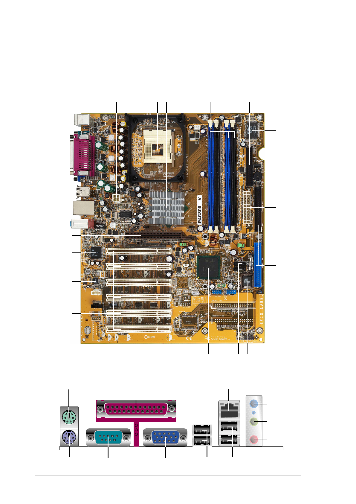
1.4 Motherboard components
Before you install the motherboard, learn about its major components and
available features to facilitate the installation and future upgrades. Refer to the
succeeding pages for the component descriptions.
15
14
1
432
5
6
7
8
13
12
16
17
11
18
10
9
19
20
21
1-4
26
25
24
23
22
Chapter 1: Product introduction

1
ATX 12V connector. This power connector connects the 4-pin 12V plug from
the ATX 12V power supply.
2
CPU socket. A 478-pin surface mount, Zero Insertion Force (ZIF) socket for
®
the Intel
Pentium® 4 Processor , with 800/533/400 MHz system bus that allows
6.4GB/s, 4.3GB/s, and 3.2GB/s data transfer rates, respectively.
3
North bridge controller . The Intel
®
865G Graphics Memory Controller Hub
(GMCH) provides the processor interface with 800/533/400 MHz frequency ,
system memory interface at 400/333/266MHz operation, and 1.5V AGP
interface that supports AGP 3.0 specification including 8X Fast Write protocol.
The GMCH interconnects to the south bridge ICH5 via the Intel® proprietary
Hub Interface.
4
DDR DIMM sockets. These four 184-pin DIMM sockets support up to 4GB
system memory using unbuffered non-ECC PC3200/2700/2100 DDR DIMMs.
5
Floppy disk connector . This connector accommodates the provided ribbon
cable for the floppy disk drive. One side of the connector is slotted to prevent
incorrect insertion of the floppy disk cable.
6
Super I/O controller . This SMSC Low Pin Count (LPC) interface provides the
commonly used Super I/O functionality . The chipset supports a highperformance floppy disk controller for a 360K/720K/1.44M/2.88M floppy disk
drive, a multi-mode parallel port, two standard compatible UARTs, and a Flash
ROM interface.
7
8
9
10
11
12
13
14
ATX power connector. This 20-pin connector connects to an ATX power
supply . The power supply must have at least 1A on the +5V standby lead
(+5VSB).
IDE connectors. These dual-channel bus master IDE connectors support
Ultra DMA100/66, PIO Modes 3 & 4 IDE devices. Both the primary (blue) and
secondary (black) connectors are slotted to prevent incorrect insertion of the
IDE ribbon cable.
Flash ROM. This 4Mb firmware contains the programmable BIOS program.
SATA connectors. These connectors support Serial A TA HDDs and allow
up to 150MB/s data transfer rate using thin 4-conductor SATA cables.
South bridge controller . The fifth-generation Intel I/O Controller Hub (ICH5)
is a subsystem that integrates various I/O functions including 2-channel
AT A100 bus master IDE controller, SA TA controller, up t o eight USB 2.0/1.1
ports, I/O APIC, SMBus 2.0 controller, LPC interface, AC’97 2.2 interface, and
PCI 2.2 interface. The ICH5 also contains the necessary arbitration and
buffering for efficient utilization of these interfaces.
PCI slots. These 32-bit PCI 2.2 expansion slots support bus master PCI
cards like SCSI or LAN cards with 133MB/s maximum throughput.
Audio CODEC. The Realtek ALC650 is an AC’97 CODEC that allows
6-channel audio playback.
LAN controller . This Realtek RTL8101L LAN controller supports
10BASE-T/100BASE-TX networking.
ASUS P4G800-V motherboard user guide
1-5
15
16
AGP 8X slot. This Accelerated Graphics Port (AGP) slot supports 1.5V AGP
8X/4X mode graphics cards for 3D graphical applications.
PS/2 mouse port. This green 6-pin connector is for a PS/2 mouse.
17
Parallel port. This 25-pin port connects a parallel printer, a scanner, or other
devices.
18
RJ-45 port. This port allows connection to a Local Area Network (LAN)
through a network hub.
19
Line In jack. This Line In (light blue) jack connects a tape player or other
audio sources. In 6-channel mode, the function of this jack becomes Bass/
Center .
20
Line Out jack. This Line Out (lime) jack connects a headphone or a
speaker. In 6-channel mode, the function of this jack becomes Front
Speaker Out.
21
Microphone jack. This Mic (pink) jack connects a microphone. In 6-channel
mode, the function of this jack becomes Rear Speaker Out.
The functions of the Line Out, Line In, and Microphone jacks change when you
select the 6-channel audio configuration as shown in the following table:
Audio 2, 4 or 6-channel configuration
Headphone/
2-Speaker 4-Speaker 6-Speaker
Light Blue Line In Line In Bass/Center
Lime Line Out Front Speaker Out Front Speaker Out
Pink Mic In Rear Speaker Out Rear Speaker Out
22
23
24
25
26
USB 2.0 ports 3 and 4. These two 4-pin Universal Serial Bus (USB) ports
are available for connecting USB 2.0 devices.
USB 2.0 ports 1 and 2. These two 4-pin Universal Serial Bus (USB) ports
are available for connecting USB 2.0 devices.
Video port. This 15-pin port is for a VGA monitor or other VGA-compatible
devices.
Serial port. This 9-pin COM1 port is for pointing devices or other serial
devices.
PS/2 keyboard port. This purple connector is for a PS/2 keyboard.
1-6
Chapter 1: Product introduction
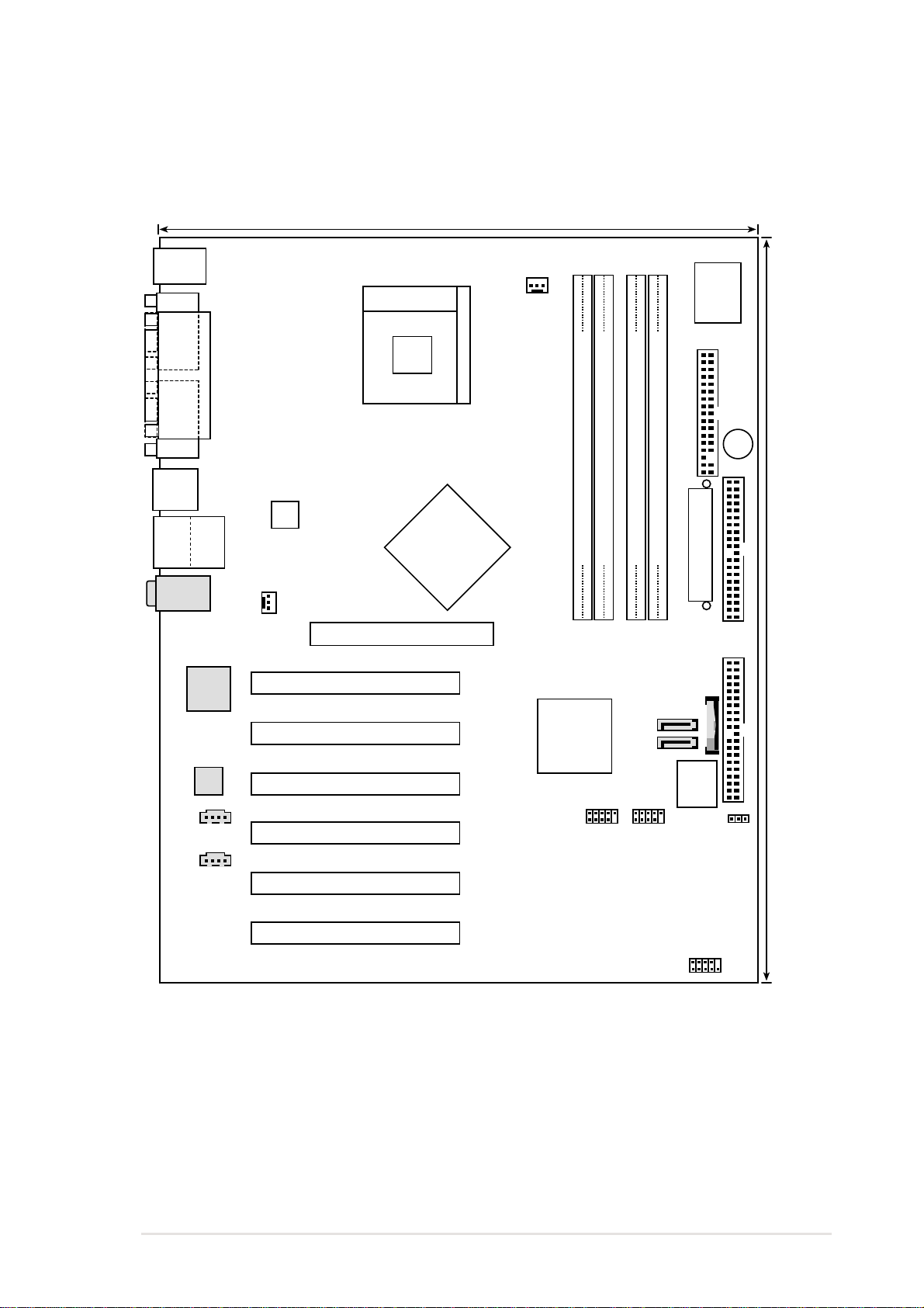
1.5 Motherboard layout
24.5cm (9.6in)
PS/2
T: Mouse
B: Keyboard
COM1
Socket 478
CPU_FAN1
I/O
Super
VGA
USB12
Bottom:
Top:
USB3
RJ-45
USB4
Top:Line In
Center:Line Out
Below:Mic In
Realtek
RTL8101L
Audio
Codec
AUX IN
PARALLEL PORT
ATX12V1
CHA_FAN1
Intel
865G
GMCH
Accelerated Graphics Port
PCI 1
PCI 2
PCI 3
PCI 4
FLOPPY1
DDR DIMM1 (64-bit, 184-pin module)
DDR DIMM2 (64-bit, 184-pin module)
P4G800-V
01
2
3
Intel
ICH5
DDR DIMM4 (64-bit, 184-pin module)
DDR DIMM3 (64-bit, 184-pin module)
ATX Power Connector
67
4
5
BATTERY1
P31
P30
4Mb
BIOS
USB2
USB1
J19
BUZZ1
SECONDARY IDE
30.5cm (12.0in)
PRIMARY IDE
CD IN
PCI 5
PCI 6
ASUS P4G800-V motherboard user guide
HPANEL1
1-7

1.6 Before you proceed
Take note of the following precautions before you install motherboard components
or change any motherboard settings.
1. Unplug the power cord from the wall socket before touching any
component.
2. Use a grounded wrist strap or touch a safely grounded object or to a metal
object, such as the power supply case, before handling components to
avoid damaging them due to static electricity.
3. Hold components by the edges to avoid touching the ICs on them.
4. Whenever you uninstall any component, place it on a grounded antistatic
pad or in the bag that came with the component.
5. Before you install or remove any component, ensure that the ATX
power supply is switched off or the power cord is detached from the
power supply. Failure to do so may cause severe damage to the
motherboard, peripherals, and/or components.
1-8
Chapter 1: Product introduction
1.7 Motherboard installation
Before you install the motherboard, study the configuration of your chassis to
ensure that the motherboard fits into it. The motherboard uses the ATX form factor
that measures 12 inches x 9.6 inches (30.5 cm x 24.5 cm).
Make sure to unplug the power cord before installing or removing the
motherboard. Failure to do so may cause you physical injury and damage
motherboard components.
1.7.1 Placement direction
When installing the motherboard, make sure that you place it into the chassis in
the correct orientation. The edge with external ports goes to the rear part of the
chassis as indicated in the image below.
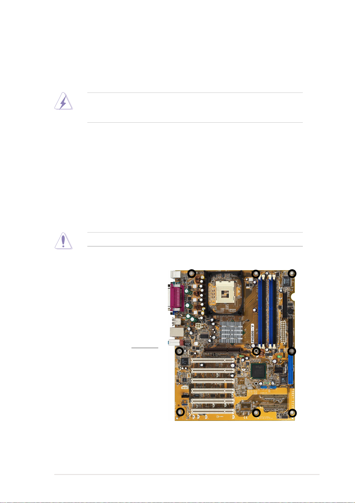
1.7.2 Screw holes
Place nine (9) screws into the holes indicated by circles to secure the motherboard
to the chassis.
Do not overtighten the screws! Doing so may damage the motherboard.
Place this side towards
the rear of the chassis
ASUS P4G800-V motherboard user guide
1-9
1.8 Central Processing Unit (CPU)
1.8.1 Overview
The motherboard comes with a surface mount 478-pin Zero Insertion Force (ZIF)
socket. The socket is designed for the Intel® Pentium® 4 Processor in the 478-pin
package with 512KB L2 cache. This processor supports 800/533/400MHz front
side bus (FSB), and allows data transfer rates of up to 6.4GB/s. The socket will
also support the Intel Prescott CPU when available.
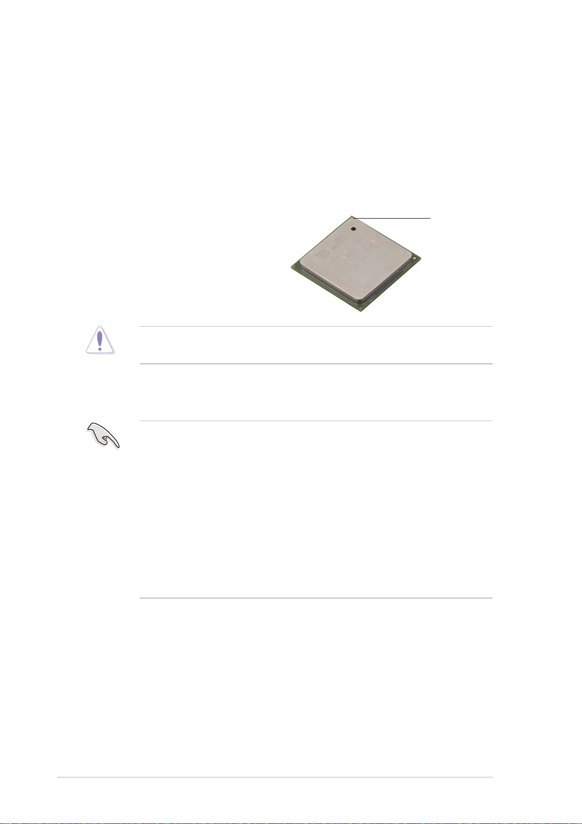
Note in the illustration that the CPU has a
gold triangular mark on one corner. This
mark indicates the processor Pin 1 that
should match a specific corner of the
CPU socket.
Incorrect installation of the CPU into the socket may bend the pins and
severely damage the CPU!
Notes on Intel® Hyper-Threading Technology
1. This motherboard supports Intel Pentium 4 CPUs with Hyper-Threading
Technology.
2. Hyper-Threading Technology is supported under Windows XP and later
versions only. If you are using any other operating systems, disable the
Hyper-Threading Techonology item in BIOS to ensure system stability and
performance.
Gold Mark
3. It is recommended that you install WinXP Service Pack 1.
4. Make sure to enable the Hyper-Threading Technology item in BIOS before
installing a supported operating system.
5. For more information on Hyper-Threading Technology , visit www.intel.com/
info/hyperthreading.
To use the Hyper-Threading Technology on this motherboard:
1. Buy an Intel Pentium 4 CPU that supports Hyper-Threading Technology. Install
the CPU.
2. Power up the system and enter BIOS Setup (see Chapter 2). Under the
Advanced Menu, make sure that the item Hyper-Threading Technology is set
to Enabled. The item appears only if you installed a CPU that supports HyperThreading Techonology.
3. Reboot the computer.
1-10
Chapter 1: Product introduction
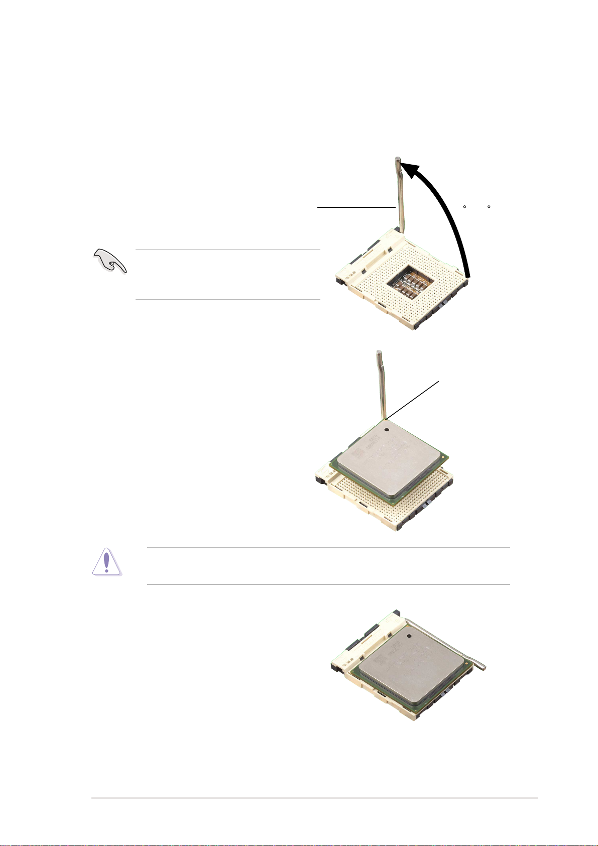
1.8.2 Installing the CPU
Follow these steps to install a CPU.
1. Locate the 478-pin ZIF socket on the motherboard.
2. Unlock the socket by pressing the
lever sideways, then lift it up to a 90°-
100° angle.
Socket Lever
Make sure that the socket lever is lifted
up to 90°-100° angle, otherwise the
CPU does not fit in completely.
3. Position the CPU above the socket
such that its marked corner matches
the base of the socket lever.
90 -100
Gold Mark
4. Carefully insert the CPU into the
socket until it fits in place.
The CPU fits only in one correct orientation. DO NOT force the CPU into the
socket to prevent bending the pins and damaging the CPU!
5. When the CPU is in place, push
down the socket lever to secure the
CPU. The lever clicks on the side tab
to indicate that it is locked.
6. Install a CPU heatsink and fan
following the instructions that came
with the heatsink package.
7. Connect the CPU fan cable to the
CPU_FAN1 connector on the
motherboard.
ASUS P4G800-V motherboard user guide
1-11
 Loading...