

ASUS m2400ne Service Manual

DISASSEMBLY PROCEDURE
A
Disassembly Procedure
Please follow the information provided in this section to perform the
complete disassembly procedure of the notebook. Be sure to use
proper tools described before.
SUS M2400Ne (ID1) Series Notebook consists of various modules. This
chapter describes the procedures for the complete notebook disassembly. In
addition, in between procedures, the detailed disassembly procedure of
individual modules will be provided for your service needs.
Chapter
The disassembly procedure consists of the following steps:
• Battery module
• Optical drive Module
• HDD Module
• Memory Module
• CPU Module
• Keyboard Module
• Mini-PCI Module
• LCD Module
• Top Case Module
• Motherboard Module
• Modem Module
• Bottom Case Module
2 - 1
DISASSEMBLY PROCEDURE
BATTERY
OPTICAL
DRIVE
REMOVAL
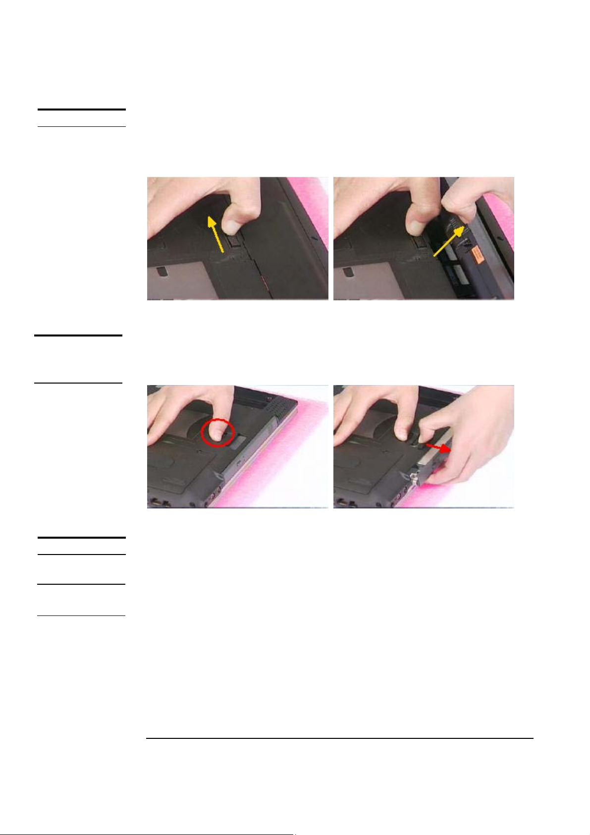
Battery module
The illustration below shows how to remove the battery module.
1. Slide the battery latch and lift the battery away from the system.
Optical Drive Module
1. Push the latch and pull the DVD-ROM module out.
HDD MODULE
HDD MODULE
REMOVAL
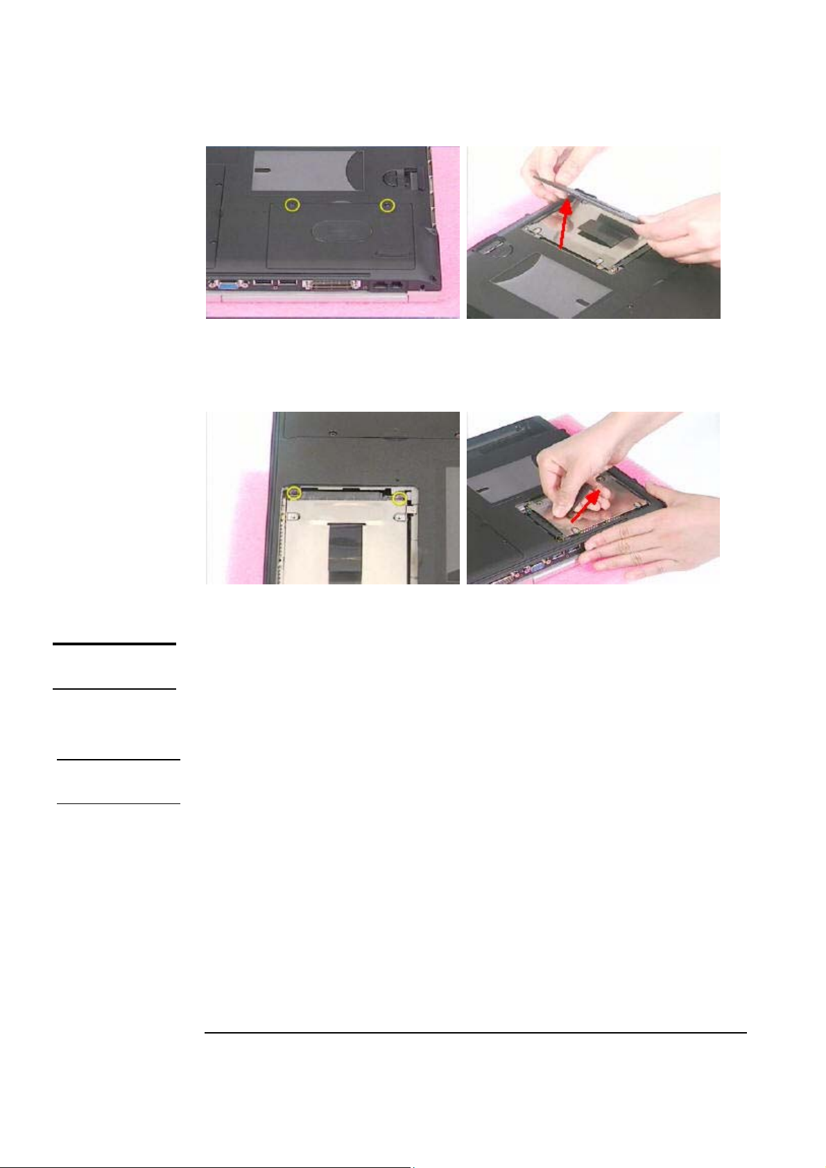
HDD Module
The illustrations below show how to remove the HDD module from the notebook.
Removing HDD Module
(1) Remove the 2 screws (M2*5) from Hard-Disk cover.
(2) Take the cover away.
2 - 2
DISASSEMBLY PROCEDURE
(3) Remove the 2 screws (M2*5).
(4) Pull the Hard Disk out of the system.
MEMORY
MODULE
MEMORY
REMOVAL
Please do not touch inside of the HDD module.
Memory Module
The illustrations below show how to remove the Memory module from the notebook.
The M2400 NE (ID1) Series Notebook comes standard with 256MB of RAM onboard.
There is one expansion SODIMM socket for you to upgrade the total memory up to
768MB with a 512 MB module
Removing Memory module
(1) Remove the 3 screws (M2*5) from DIMM cover.
(2) Take the cover away.
(3) Remove SO-DIMM by opening the two latches to pop up it.
(4) Pull the SO-DIMM out.
2 - 3

DISASSEMBLY PROCEDURE
CPU MODULE
REMOVAL
CPU Module
The illustrations below show how to remove the CPU module from the notebook.
(1) Remove the 2 screws (M2*5) from FAN and gently lift the CPU fan.
(2) Disconnect the CPU FAN cable and remove the 4 screws (M2*5) from
Heat-Sink.
2 - 4

DISASSEMBLY PROCEDURE
(3) Then lift the CPU heat-sink module and carefully remove the CPU
thermal pad.
K/B MODULE
(3) Turn the non-removable screw here 180 degrees counter-clockwise to
loose the CPU and squeeze the vacuum handling pump and use it to lift
the CPU away.
Keyboard Module
The illustration below shows how to remove the K/B plate.
2 - 5
 Loading...