

Version 1.0
Published October 2016
Copyright©2016 ASRock INC. All rights reserved.
Copyright Notice:
No part of this documentation may be reproduced, transcribed, transmitted, or
translated in any language, in any form or by any means, except duplication of
documentation by the purchaser for backup purpose, without written consent of
ASRock Inc.
Products and corporate names appearing in this documentation may or may not
be registered trademarks or copyrights of their respective companies, and are used
only for identication or explanation and to the owners’ benet, without intent to
infringe.
Disclaimer:
Specications and information contained in this documentation are furnished for
informational use only and subject to change without notice, and should not be
constructed as a commitment by ASRock. ASRock assumes no responsibility for
any errors or omissions that may appear in this documentation.
With respect to the contents of this documentation, ASRock does not provide
warranty of any kind, either expressed or implied, including but not limited to
the implied warranties or conditions of merchantability or tness for a particular
purpose.
In no event shall ASRock, its directors, ocers, employees, or agents be liable for
any indirect, special, incidental, or consequential damages (including damages for
loss of prots, loss of business, loss of data, interruption of business and the like),
even if ASRock has been advised of the possibility of such damages arising from any
defect or error in the documentation or product.
is device complies with Part 15 of the FCC Rules. Operation is subject to the following
two conditions:
(1) this device may not cause harmful interference, and
(2) this device must accept any interference received, including interference that
may cause undesired operation.
CALIFORNIA, USA ONLY
e Lithium battery adopted on this motherboard contains Perchlorate, a toxic substance
controlled in Perchlorate Best Management Practices (BMP) regulations passed by the
California Legislature. When you discard the Lithium battery in California, USA, please
follow the related regulations in advance.
“Perchlorate Material-special handling may apply, see ww w.dtsc.ca.gov/hazardouswaste/
perchlorate”
ASRock Website: http://www.asrock.com

AUSTRALIA ONLY
Our goods come with guarantees that cannot be excluded under the Australian Consumer
Law. You are entitled to a replacement or refund for a major failure and compensation for
any other reasonably foreseeable loss or damage caused by our goods. You are also entitled
to have the goods repaired or replaced if the goods fail to be of acceptable quality and the
failure does not amount to a major failure. If you require assistance please call ASRock Tel
: +886-2-28965588 ext.123 (Standard International call charges apply)
e terms HDMI™ and HDMI High-Denition Multimedia Interface, and the HDMI
logo are trademarks or registered trademarks of HDMI Licensing LLC in the United
States and other countries.

Contents
Chapter 1 Introduction 1
1.1 Package Contents 1
1.2 Specications 2
1.3 Motherboard Layout 7
1.4 I/O Panel 9
1.5 WiFi-802.11ac Module and ASRock WiFi 2.4/5 GHz Antenna 11
Chapter 2 Installation 13
2.1 Installing the CPU 14
2.2 Installing the CPU Fan and Heatsink 17
2.3 Installing Memory Modules (DIMM) 18
2.4 Expansion Slot (PCI Express Slot) 20
2.5 Jumpers Setup 21
2.6 Onboard Headers and Connectors 22
2.7 M.2_SSD (NGFF) Module Installation Guide 26
Chapter 3 Software and Utilities Operation 29
3.1 Installing Drivers 29
3.2 A-Tuning 30
3.2.1 Installing A-Tuning 30
3.2.2 Using A-Tuning 30
3.3 ASRock Live Update & APP Shop 33
3.3.1 UI Overview 33
3.3.2 Apps 34

3.3.3 BIOS & Drivers 37
3.3.4 Setting 38
3.4 Enabling USB Ports for Windows® 7 Installation 39
Chapter 4 UEFI SETUP UTILITY 42
4.1 Introduction 42
4.2 EZ Mode 43
4.3 Advanced Mode 44
4.3.1 UEFI Menu Bar 44
4.3.2 Navigation Keys 45
4.4 Main Screen 46
4.5 OC Tweaker Screen 47
4.6 Advanced Screen 55
4.6.1 CPU Conguration 56
4.6.2 Chipset Conguration 58
4.6.3 Storage Conguration 61
4.6.4 Super IO Conguration 62
4.6.5 ACPI Conguration 63
4.6.6 USB Conguration 64
4.6.7 Trusted Computing 65
4.7 Tools 66
4.8 Hardware Health Event Monitoring Screen 69
4.9 Security Screen 71
4.10 Boot Screen 72
4.11 Exit Screen 75


Z270M-ITX/ac
Chapter 1 Introduction
ank you for purchasing ASRock Z270M-ITX/ac motherboard, a reliable
motherboard produced under ASRock’s consistently stringent quality control.
It delivers excellent performance with robust design conforming to ASRock’s
commitment to quality and endurance.
In this documentation, Chapter 1 and 2 contains the introduction of the
motherboard and step-by-step installation guides. Chapter 3 contains the operation
guide of the soware and utilities. Chapter 4 contains the conguration guide of
the BIOS setup.
Becau se the motherboard specications and the BIOS soware might be updated, the
content of this documentation will be subject to change without notice. In case any modications of this documentation occur, the updated version will be available on ASRock’s
website w ithout further notice. If you require technical support relate d to this motherboard, please visit our website for specic information about the model you are using. You
may nd the l atest VGA cards and CPU support list on ASRock ’s website a s well. ASRock
website http://www.asrock.com.
1.1 Package Contents
ASRock Z270M-ITX/ac Motherboard (Mini-ITX Form Factor)
•
ASRock Z270M-ITX/ac Quick Installation Guide
•
ASRock Z270M-ITX/ac Support CD
•
2 x Serial ATA (SATA) Data Cables (Optional)
•
1 x I/O Panel Shield
•
2 x ASRock WiFi 2.4/5 GHz Antennas (O pt iona l)
•
1 x Screw for M.2 Socket (Optional)
•
English

1.2 Specications
Platform
CPU
Chipset
Memory
•
•
•
•
•
•
•
•
•
•
•
* 3733+(OC) memory frequency can only be achieved when a
single memory module is installed (Single channel memory).
* Please refer to Memory Support List on ASRock's website for
more information. (http://www.asrock.com/)
** 7th Gen Intel® CPU supports DDR4 2400 natively; 6th Gen
Intel® CPU supports DDR4 2400 by overclocking.
•
•
•
•
Mini-ITX Form Factor
Supports 7th and 6th Generation Intel® CoreTM i7/i5/i3/
Pentium®/Celeron® Processors (Socket 1151)
Digi Power design
6 Power Phase design
Supports Intel® Turbo Boost 2.0 Technology
Supports Intel® K-Series unlocked CPUs
Supports ASRock BCLK Full-range Overclocking
Intel® Z270
Dual Channel DDR4 Memory Technology
2 x DDR4 DIMM Slots
Supports DDR4 3733+(OC)*/3600+(OC)/3200(OC)/2933
(OC)/2800(OC)/2400**/2133 non-ECC, un-buered memory
Supports ECC UDIMM memory modules (operate in non-
ECC mode)
Max. capacity of system memory: 32GB
Supports Intel® Extreme Memory Prole (XMP) 2.0
15μ Gold Contact in DIMM Slots
1 x PCI Express 3.0 x16 Slot (PCIE1: x16 mode)
Expansion
Slot
•
* Supports NVMe SSD as boot disks
1 x Vertical M.2 Socket (Key E) with the bundled WiFi-
•
802.11ac module (on the rear I/O).
English
2 3

Z270M-ITX/ac
Graphics
* Intel® HD Graphics Built-in Visuals and the VGA outputs can
be supported only with processors which are GPU integrated.
Supports Intel® HD Graphics Built-in Visuals : Intel® Quick
•
Sync Video with AVC, MVC (S3D) and MPEG-2 Full
HW Encode1, Intel® InTruTM 3D, Intel® Clear Video HD
Technology, Intel® InsiderTM, Intel® HD Graphics
Gen9 LP, DX11.3, DX12
•
HWAEncode/Decode: VP8, HEVC 8b, VP9, HEVC 10b (For
•
7th Gen Intel® CPU)
HWA Encode/Decode: VP8 , HEVC 8b; GPU/SWEncode/
•
Decode: VP9, HEVC 10b (For 6th Gen Intel® CPU)
Max. shared memory 1024MB
•
* e size of ma ximum shared memory may vary from dierent
operating systems.
ree graphics output options: DVI-D port and 2 x HDMI
•
ports
Supports Triple Monitor
•
Supports HDMI with max. resolution up to 4K x 2K
•
(4096x2160) @ 24Hz / (3840x2160) @ 30Hz
Supports DVI-D with ma x. resolution up to 1920x1200 @
•
60Hz
Supports Auto Lip Sync, Deep Color (12bpc), xvYCC and
•
HBR (High Bit Rate Audio) with HDMI Port
(Compliant HDMI monitor is required)
Supports HDCP with DVI-D and HDMI Ports
•
Supports Full HD 1080p Blu-ray (BD) playback with DVI-D
•
and HDMI Ports
Audio
7.1 CH HD Audio with Content Protection (Realtek ALC892
•
Audio Codec)
* To congure 7.1 CH HD Audio, it is required to use an HD
front panel audio module and enable the multi-channel audio
feature through the audio driver.
Premium Blu-ray Audio support
•
Supports Surge Protection (ASRock Full Spike Protection)
•
Nichicon Fine Gold Series Audio Caps
•
English

LAN
Wireless
LAN
Rear Panel
I/O
Gigabit LAN 10/100/10 00 Mb/s
•
1 x Giga PHY Intel® I219V, 1 x GigaLAN Intel® I211V
•
Supports Wake-On-LAN
•
Supports Lightning/ESD Protection (ASRock Full Spike
•
Protection)
Supports Dual LAN with Teaming
•
Supports Energy Ecient Ethernet 802.3az
•
Supports PXE
•
Intel® 802.11ac WiFi Module (Free Bundle)
•
Supports IEEE 802.11a/b/g/n/ac
•
Supports Dual-Band (2.4/5 GHz)
•
Supports high speed wireless connections up to 433Mbps
•
Supports Bluetooth 4.0 / 3.0 + High speed class II
•
2 x Antenna Ports
•
1 x PS/2 Mouse/Keyboard Port
•
1 x DVI-D Port
•
2 x HDMI Ports
•
2 x USB 2.0 Ports (Supports ESD Protection (ASRock Full
•
Spike Protection))
6 x USB 3.0 Ports (Supports ESD Protection (ASRock Full
•
Spike Protection))
2 x RJ-45 LAN Ports with LED (ACT/LINK LED and SPEED
•
LED)
HD Audio Jacks: Line in / Front Speaker / Microphone
•
6 x SATA3 6.0 Gb/s Connectors, support RAID (RAID 0,
Storage
English
•
RAID 1, RAID 5, RAID 10, Intel Rapid Storage Technology
15 and Intel Smart Response Technology), NCQ, AHCI and
Hot Plug*
* If M2_1 is occupied by a SATA-type M.2 device, SATA3_0 will
be disabled.
1 x Ultra M.2 Socket, supports type 2230/2242/2260/2280
•
M.2 SATA3 6.0 Gb/s module and M.2 PCI Express module
up to Gen3 x4 (32 Gb/s)**
** Supports Intel® OptaneTM Technology
** Supports NVMe SSD as boot disks
** Supports ASRock U.2 Kit
4 5

Connector
BIOS
Feature
Z270M-ITX/ac
1 x TPM Header
•
1 x Chassis Intrusion Header
•
1 x CPU Fan Connector (4-pin)
•
* e CPU Fan Connector supports the CPU fan of ma ximum
1A (12W) fan power.
1 x Chassis Optional/Water Pump Fan Connector (4-pin)
•
(Smart Fan Speed Control)
* e Chassis Optional/Water Pump Fan can auto detect if 3-pin
or 4-pin fan is in use.
* e Chassis Optional/Water Pump Fan supports the water
cooler fan of maximum 1.5A (18W) fan power.
1 x 24 pin ATX Power Connector
•
1 x 8 pin 12V Power Connector
•
1 x Front Panel Audio Connector
•
1 x USB 2.0 Header (Supports 2 USB 2.0 ports) (Supports
•
ESD Protection (ASRock Full Spike Protection))
1 x USB 3.0 Header (Supports 2 USB 3.0 ports) (Supports
•
ESD Protection (ASRock Full Spike Protection))
AMI UEFI Legal BIOS with multilingual GUI support
•
ACPI 6.0 Compliant wake up events
•
SMBIOS 2.7 Support
•
CPU, GT_CPU, DRAM, PCH 1.0V Voltage Multi-adjustment
•
Hardware
Monitor
CPU / Chassis Optional/Water Pump temperature sensing
•
CPU / Chassis Optional/Water Pump Fan Tachometer
•
CPU / Chassis Optional/Water Pump Quiet Fan (Auto adjust
•
chassis fan speed by CPU temperature)
CPU / Chassis Optional/Water Pump Fan multi-speed con-
•
trol
CASE OPEN detection
•
Voltage monitoring: +12V, +5V, +3.3V, CPU Vcore
•
English
Microso® Windows® 10 64-bit (For 7th Gen Intel® CPU)
OS
•
Microso® Windows® 10 64-bit / 8.1 64-bit / 7 32-bit / 7 64-
•
bit (For 6th Gen Intel® CPU)
* To install Windows® 7 OS, a modied installation disk with
xHCI drivers packed into the ISO le is required. Please refer to
page 39 for more detailed instructions.
* For the updated Windows® 10 driver, please visit ASRock ’s
website for details: http://ww w.asrock.com
FCC, CE, WHQL, RCM, BSMI
Certications
* For detailed product information, please visit our website: http://www.asrock .com
Please realize that the re is a certain r isk involved with overclo cking, including adju sting
the setting in the BIOS, applying Untied Overclocking Technolog y, or using third-party
overclocking to ols. O verclocking may aect your system’s stability, or even cause damage to
the components and devices of your system. It should be done at your ow n risk and expense.
We are not responsibl e for possible damage caused by overclo cking.
•
ErP/EuP ready (ErP/EuP ready power supply is required)
•
English
6 7
PCIE1
DDR 4_A1 (6 4 bit, 28 8-pin m odule )
DDR 4_B1 (6 4 bit, 28 8-pin m odule )
CPU_FAN1
CHA_FAN1/W_PUMP
6
RoHS
Z270M-ITX/ac
3
7
9
14
8
USB 2.0
T: USB1
B: USB2
PS2
Keyb oard
/Mou se
181716
15
AUDIO
CODEC
5
1
HD_AUDIO1
1
SPEAKER 1
Intel
Z270
ATXPWR1
USB3_ 6_7
1
HDM I2
4
2
PANEL1
HDLED RESET
PLED PWRBTN
1
TPMS1
1
1
CI1
HDMI1
DVI 1
Top:
LINE I N
Cent er:
FRON T
Bott om:
MIC IN
SATA3_3
SATA3_2
1
CLRMOS1
SATA3_1
SATA3_0
1
USB_3_4
SATA3_5
SATA3_4
M2_ 1
C 4
C 3C 2C 1
T
T
T
T
Top:
RJ-45
USB 3.0
T: USB4
B: USB5
Top:
RJ-45
USB 3.0
T: USB2
B: USB3
USB 3.0
T: USB0
B: USB1
1
10
11
12
13
19
BIOS
ROM
M2_WIFI1
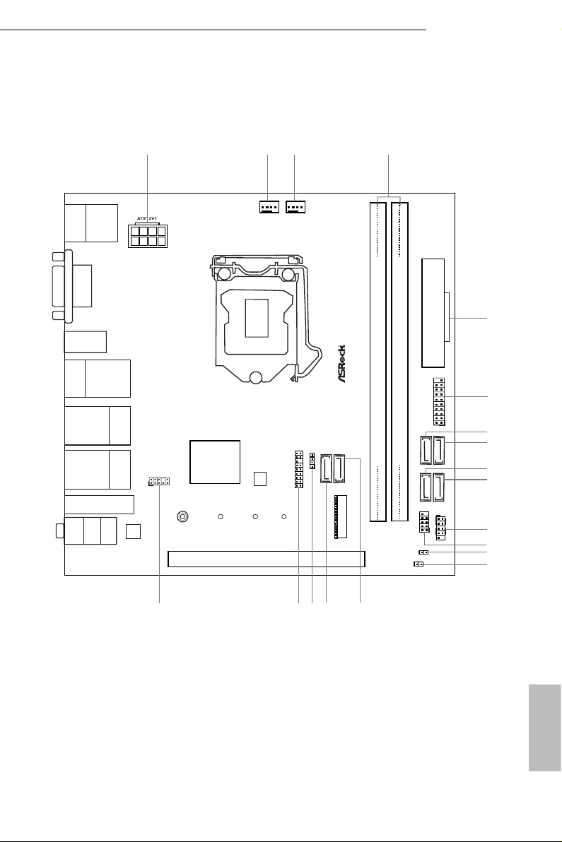
1.3 Motherboard Layout
Z270M-ITX/ac
English

No. Description
1 ATX 12V Power Connector (ATX12V1)
2 Chassis Fan / Waterpump Fan Connector (CHA_FAN1/W_PUMP)
3 CPU Fan Connector (CPU_FAN1)
4 2 x 288-pin DDR4 DIMM Slots (DDR4_A1, DDR4_B1)
5 ATX Power Connector (ATXPWR1)
6 USB 3.0 Header (USB_6_7)
7 SATA3 Connector (SATA3_1)
8 SATA3 Connector (SATA3_0)
9 SATA3 Connector (SATA3_3)
10 SATA3 Connector (SATA3_2)
11 System Panel Header (PANEL1)
12 USB 2.0 Header (USB_3_4)
13 Clear CMOS Jumper (CLRMOS1)
14 Chassis Intrusion Header (CI1)
15 SATA3 Connec tor (SATA3_4)
16 SATA3 Connector (SATA3_5)
17 Chassis Speaker Header (SPEAKER1)
18 TPM Header (TPMS1)
19 Front Panel Audio Header (HD_AUDIO1)
English
8 9
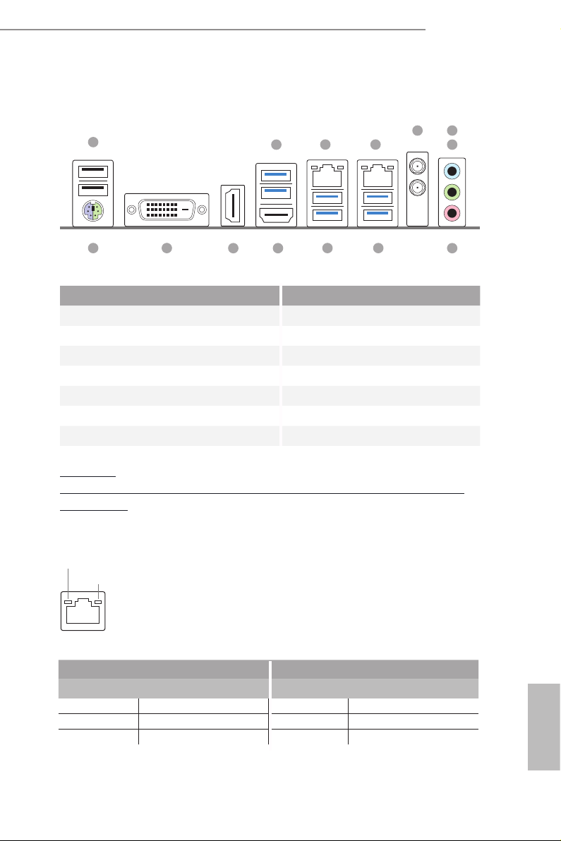
1.4 I/O Panel
1
Z270M-ITX/ac
6
2
3 4
5
7
14
13
12
11
910
No. Description No. Description
1 USB 2.0 Ports (USB12) 8 Microphone (Pink)**
2 USB 3.0 Ports (USB3_01) 9 USB 3.0 Ports (USB3_45)
3 LAN RJ-45 Port* 10 USB 3.0 Ports (USB3_23)
4 LAN RJ-45 Port* 11 HDMI Port (HDMI2)
5 Antenna Ports (M2_WIFI1) 12 HDMI Port (HDMI1)
6 Line In (Light Blue)** 13 DVI-D Port (DVI1)
7 Front Speaker (Lime)** 14 PS/2 Mouse/Keyboard Port
CAU TION:
For operating system installation, be sure to plug your USB ash drive into the USB 2.0
Ports (USB12).
* ere are two LEDs on each LAN port. Please refer to the table below for the LAN port LED indications .
ACT/LINK LED
SPEED LED
LAN Por t
8
Activity / Link LED Speed LED
Status Description Status Description
O No Link O 10Mbps connection
Blinking Data Activity Orange 100Mbps connection
On Link Green 1Gbps connection
English
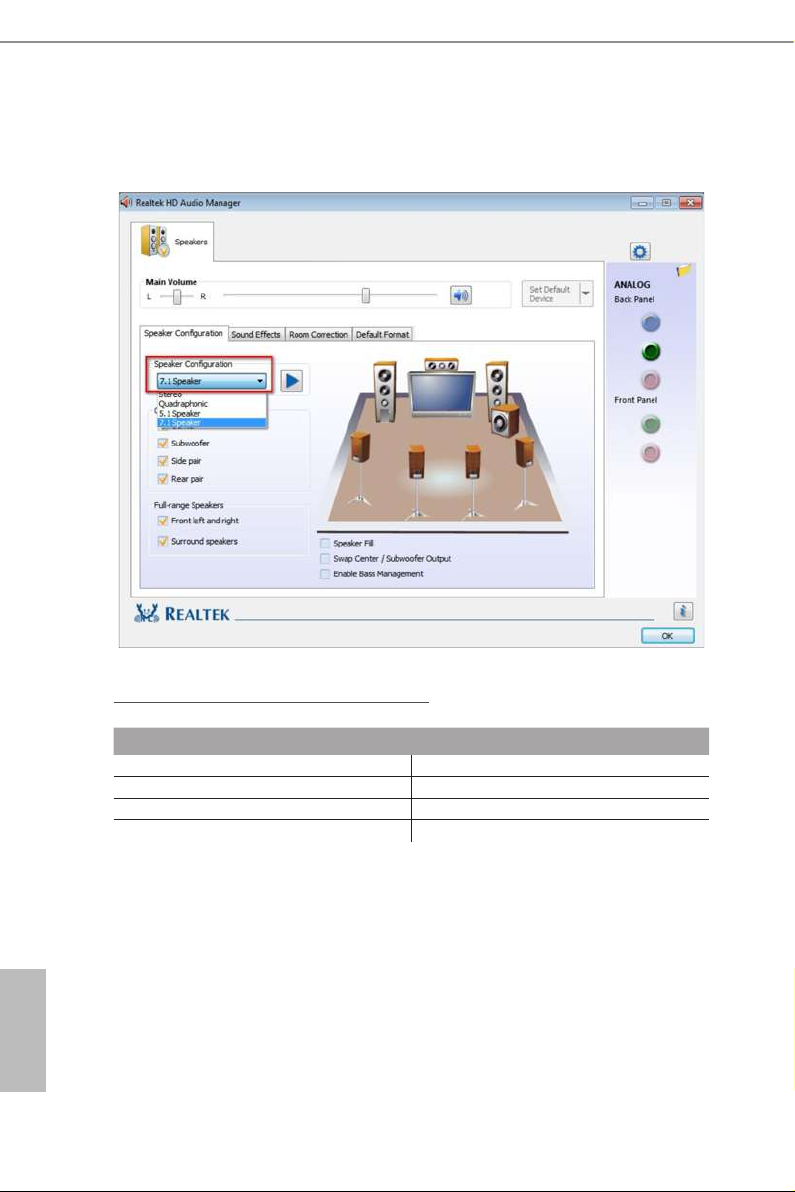
** To congure 7.1 CH HD Audio, it i s required to use an HD front panel audio module and enable the multichannel audio feature through the audio driver.
Please set Speaker Conguration to “7.1 Speaker”in the Realtek HD Audio Manager.
Function of the Audio Ports in 7.1-channel Conguration:
Port Function
Light Blue (Rear panel) Rear Speaker Out
Lime (Rear panel) Front Speaker Out
Pink (Rear panel) Central /Subwoofer Speaker Out
Lime (Front panel) Side Speaker Out
English
10 11
Z270M-ITX/ac
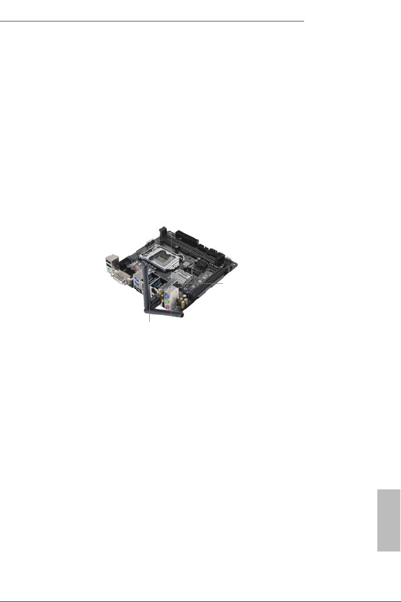
1.5 WiFi-802.11ac Module and ASRock WiFi 2.4/5 GHz Antenna
WiFi-802.11ac + BT Module
is motherboard comes with an exclusive WiFi 802.11 a/b/g/n/ac + BT v4.0
module (pre-installed on the rear I/O panel) that oers support for WiFi 802.11 a/b/
g/n/ac connectivity standards and Bluetooth v4.0. WiFi + BT module is an easy-to-
use wireless local area network (WLAN) adapter to support WiFi + BT. Bluetooth
v4.0 standard features Smart Ready technology that adds a whole new class of
functionality into the mobile devices. BT 4.0 also includes Low Energy Technology
and ensures extraordinary low power consumption for PCs.
* e transmission speed may vary according to the environment.
WiFi + BT Module
(pre-installed Intel® Dual Band
Wireless-AC 3160)
ASRock WiFi 2.4/5 GHz Antennas
(included in the package)
English
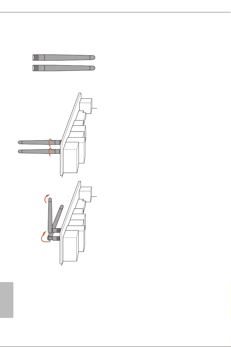
WiFi Antennas Installation Guide
Step 1
Prepare the WiFi 2.4/5 GHz Antennas that come
with the package.
Step 2
Connect the two WiFi 2.4/5 GHz Antennas to
the antenna connectors. Turn the antenna clock-
wise until it is securely connected.
Step 3
Set the WiFi 2.4/5 GHz Antenna as shown in the
illustration.
*You may need to adjust the direction of
the antenna for a stronger signal.
English
12 13

Chapter 2 Installation
is is a Mini-ITX form factor motherboard. Before you install the motherboard,
study the conguration of your chassis to ensure that the motherboard ts into it.
Pre-installation Precautions
Take note of the following precautions before you install motherboard components
or change any motherboard settings.
Make sure to unplug the power cord before installing or removing the motherboard
•
components. Failure to do so may cause physical injuries and damages to motherboard
components.
In order to avoid damage from static electricity to the motherboard’s components,
•
NEVER place your motherboard directly on a carpet. Also remember to use a grounded
wrist strap or touch a safety grounded object before you handle the components.
Hold components by the edges and do not touch the ICs.
•
Whenever you uninstall any components, place them on a grounded anti-static pad or
•
in the bag that comes with the components.
When placing screws to secure the motherboard to the chassis, please do not over-
•
tighten the screws! Doing so may damage the motherboard.
Z270M-ITX/ac
English
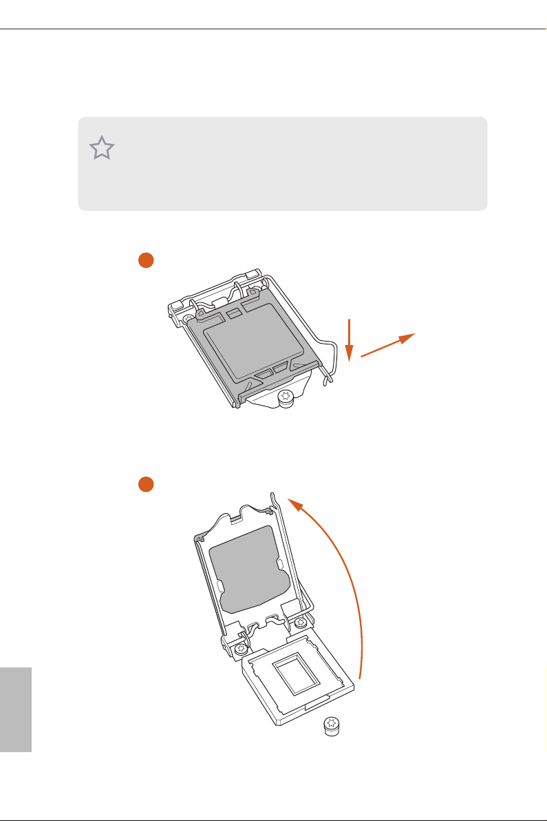
2.1 Installing the CPU
1. Before you insert the 1151-Pin CPU into the socket, please check if the PnP cap is on the
socket, if the CPU surface is unclean, or if there are any bent pins in the socket. Do not
force to in sert the CPU into the socket if above situation is found. Otherwise, the CPU
will be seriously damaged.
2. Unplug all power c ables before in stalling the CPU.
1
2
A
B
English
14 15
Z270M-ITX/ac
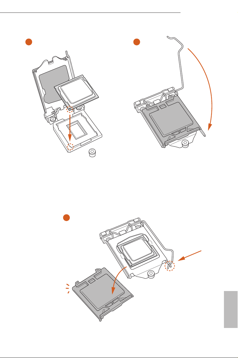
3
4
5
English

Please save and replace the cover if the processor i s removed. e cover must be placed if
you wish to return the motherboard for aer service.
English
16 17
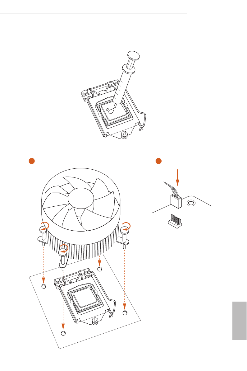
2.2 Installing the CPU Fan and Heatsink
1 2
Z270M-ITX/ac
FAN
CPU_
English
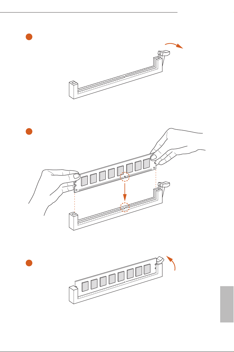
2.3 Installing Memory Modules (DIMM)
is motherboard provides two 288-pin DDR4 (Double Data Rate 4) DIMM slots.
It is not allowed to install a DDR, DDR2 or DDR3 memory module into a DDR4 slot; otherwise, this motherboard and DIMM may be damaged.
e DIMM only ts in one correct orientation. It will cause permanent dam age to the
motherboard and the DIMM if you force the DIMM into the slot at incorrect orientation.
English
18 19
Z270M-ITX/ac
1
2
3
English
 Loading...