

Version 1.0
Published June 2015
Copyright©2015 ASRock INC. All rights reserved.
Copyright Notice:
No part of this documentation may be reproduced, transcribed, transmitted, or
translated in any language, in any form or by any means, except duplication of
documentation by the purchaser for backup purpose, without written consent of
ASRock Inc.
Products and corporate names appearing in this documentation may or may not
be registered trademarks or copyrights of their respective companies, and are used
only for identication or explanation and to the owners’ benet, without intent to
infringe.
Disclaimer:
Specications and information contained in this documentation are furnished for
informational use only and subject to change without notice, and should not be
constructed as a commitment by ASRock. ASRock assumes no responsibility for
any errors or omissions that may appear in this documentation.
With respect to the contents of this documentation, ASRock does not provide
warranty of any kind, either expressed or implied, including but not limited to
the implied warranties or conditions of merchantability or tness for a particular
purpose.
In no event shall ASRock, its directors, ocers, employees, or agents be liable for
any indirect, special, incidental, or consequential damages (including damages for
loss of prots, loss of business, loss of data, interruption of business and the like),
even if ASRock has been advised of the possibility of such damages arising from any
defect or error in the documentation or product.
is device complies with Part 15 of the FCC Rules. Operation is subject to the following
two conditions:
(1) this device may not cause harmful interference, and
(2) this device must accept any interference received, including interference that
may cause undesired operation.
CALIFORNIA, USA ONLY
e Lithium battery adopted on this motherboard contains Perchlorate, a toxic substance
controlled in Perchlorate Best Management Practices (BMP) regulations passed by the
California Legislature. When you discard the Lithium battery in California, USA, please
follow the related regulations in advance.
“Perchlorate Material-special handling may apply, see www.dtsc.ca.gov/hazardouswaste/
perchlorate”
ASRock Website: http://www.asrock.com

e terms HDMI™ and HDMI High-Denition Multimedia Interface, and the HDMI
logo are trademarks or registered trademarks of HDMI Licensing LLC in the United
States and other countries.
1
English
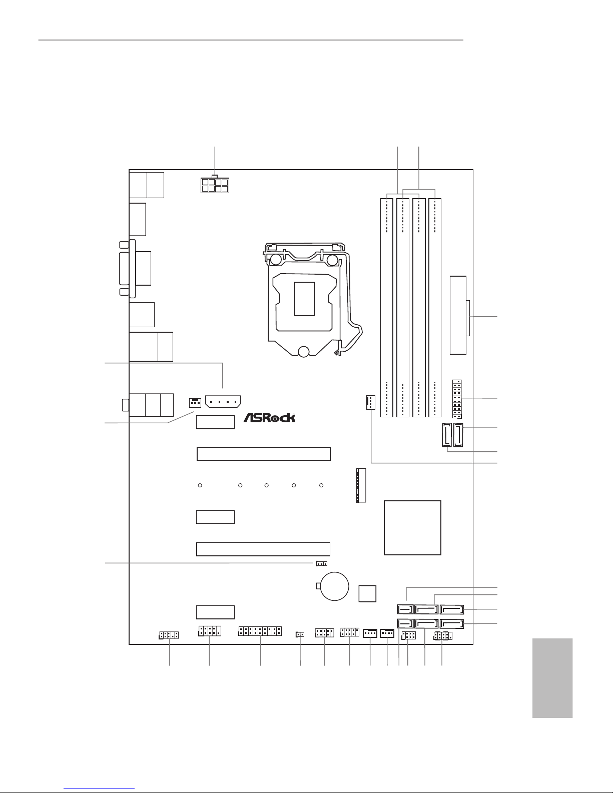
Z170 Pro4S
Motherboard Layout
Intel
Z170
DDR 4_ A2 (64 b it, 28 8- pin mo du le)
DDR 4_ A1 (64 b it, 28 8- pin mo du le)
DDR 4_ B2 (64 b it, 28 8- pin mo du le)
DDR 4_ B1 (64 b it, 28 8- pin mo du le)
ATX12V 1
USB 3.0
T: USB 1
B: U SB2
ATXPWR1
PCIE 2
Top:
RJ- 45
USB 3. 0
T: US B5
B: USB 6
PCIE 4
HDLED RESET
PLED PWR BTN
PANEL1
1
USB_1 _2
1
1
SPK_PL ED1
COM1
1
1
HD_AU DIO1
Z170 Pro4S
PCIE 1
RoHS
8
6
7
11
13
14
15
16
17
18
19
22
HDMI1
DVI1
USB 3.0
T: USB 3
B: U SB4
1
3
2
20
Ult ra M .2
PCI e Ge n3 x4
PS2
Keyb oard
/Mou se
CMO S
Bat te ry
CLRMOS 1
1
PCIE 3
M2_ 1
CT2CT3CT4CT5
24
10
4
USB3 _7_8
1
21
CPU_FA N1
12
9
USB_3 _4
1
23
1
TPMS1
PCIE 5
CT1
5
PCI Ex pr ess 3. 0
Front USB 3.0
CHA_FA N2
128 Mb
BIO S
Top:
LIN E IN
Cen ter:
FRO N T
Bot tom:
MIC IN
PCIE _PWR1
CHA_FAN 3
SATA3_1
SATA3_0
SATA3_5
SATA3_4
SATA3_3
SATA3_2
CHA_FA N1
CI1
1
25
27
26
SATA_EXP 1
SATA_EXP 0

2
English
No. Description
1 ATX 12V Power Connector (ATX12V1)
2 2 x 288-pin DDR4 DIMM Slots (DDR4_A1, DDR4_B1)
3 2 x 288-pin DDR4 DIMM Slots (DDR4_A2, DDR4_B2)
4 ATX Power Connector (ATXPWR1)
5 USB 3.0 Header (USB3_7_8)
6 SATA3 Connector (SATA3_0)
7 SATA3 Connector (SATA3_1)
8 CPU Fan Connector (CPU_FAN1)
9 SATA Express Connector (SATA_EXP1)
10 SATA3 Connector (SATA3_5)
11 SATA3 Connector (SATA3_4)
12 SATA3 Connector (SATA3_2)
13 System Panel Header (PANEL1)
14 SATA3 Connector (SATA3_3)
15 Power LED and Speaker Header (SPK_PLED1)
16 SATA Express Connector (SATA_EXP0)
17 Chassis Fan Connector (CHA_FAN2)
18 Chassis Fan Connector (CHA_FAN1)
19 USB 2.0 Header (USB_3_4)
20 USB 2.0 Header (USB_1_2)
21 Chassis Intrusion Header (CI1)
22 TPM Header (TPMS1)
23 COM Port Header (COM1)
24 Front Panel Audio Header (HD_AUDIO1)
25 Clear CMOS Jumper (CLRMOS1)
26 Chassis Fan Connector (CHA_FAN3)
27 PCIe Power Connector (PCIE_PWR1)
3
English
Z170 Pro4S
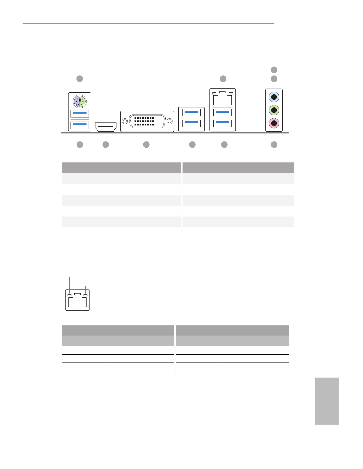
I/O Panel
No. Description No. Description
1 PS/2 Mouse/Keyboard Port 6 USB 3.0 Ports (USB3_5_6)
2 LAN RJ-45 Port* 7 USB 3.0 Ports (USB3_3_4)
3 Line In (Light Blue)** 8 DVI-D Port
4 Front Speaker (Lime)** 9 HDMI Port
5 Microphone (Pink)** 10 USB 3.0 Ports (USB3_1_2)
10 569
8
4
3
1 2
7
* ere are two LEDs on the LAN port. Please refer to the table below for the LAN port LED indications.
Activity / Link LED Speed LED
Status Description Status Description
O No Link O 10Mbps connection
Blinking Data Activity Orange 100Mbps connection
On Link Green 1Gbps connection
ACT/LINK LED
SPEED LED
LAN Por t
4
English
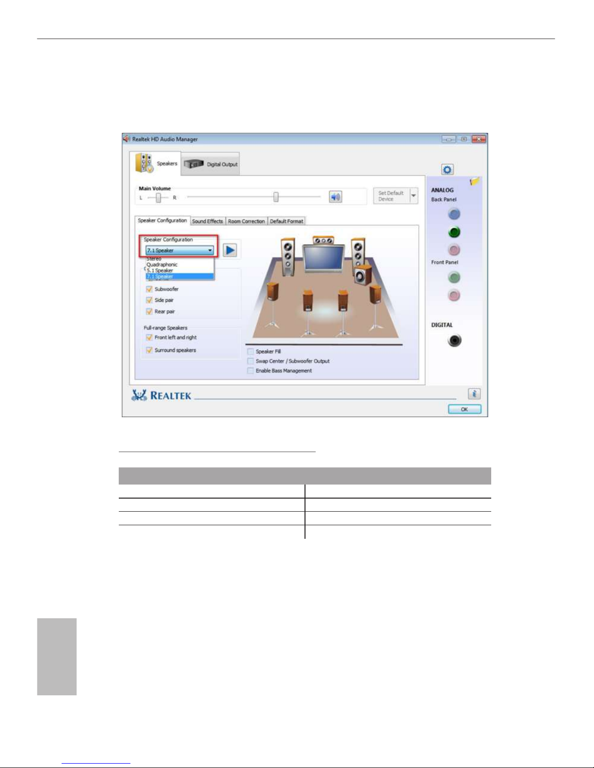
** To congure 7.1 CH HD Audio, it is required to use an HD front panel audio module and enable the multichannel audio feature through the audio driver.
Please set Speaker Conguration to “7.1 Speaker”in the Realtek HD Audio Manager.
Function of the Audio Ports in 7.1-channel Conguration:
Port Function
Light Blue (Rear panel) Rear Speaker Out
Lime (Rear panel) Front Speaker Out
Pink (Rear panel) Central /Subwoofer Speaker Out
Lime (Front panel) Side Speaker Out
5
English
Z170 Pro4S
Chapter 1 Introduction
ank you for purchasing ASRock Z170 Pro4S motherboard, a reliable motherboard
produced under ASRock’s consistently stringent quality control. It delivers excellent
performance with robust design conforming to ASRock’s commitment to quality
and endurance.
In this documentation, Chapter 1 and 2 contains the introduction of the
motherboard and step-by-step installation guides. Chapter 3 contains the operation
guide of the soware and utilities. Chapter 4 contains the conguration guide of
the BIOS setup.
1.1 Package Contents
•
ASRock Z170 Pro4S Motherboard (ATX Form Factor)
•
ASRock Z170 Pro4S Quick Installation Guide
•
ASRock Z170 Pro4S Support CD
•
2 x Serial ATA (SATA) Data Cables (Optional)
•
1 x I/O Panel Shield
•
1 x Screw for M.2 Socket
Because the motherboard specications and the BIOS soware might be updated, the
content of this documentation will be subject to change without notice. In case any
modications of this documentation occur, the updated version will be available on
ASRock’s website without further notice. If you require technical support related to
this motherboard, please visit our website for specic information about the model
you are using. You may nd the latest VGA cards and CPU support list on ASRock’s
website as well. ASRock website http://www.asrock.com.

6
English
1.2 Specications
Platform
•
ATX Form Factor
•
Solid Capacitor design
•
High Density Glass Fabric PCB
CPU
•
Supports 6th Generation Intel® CoreTM i7/i5/i3/Pentium®/
Celeron® Processors (Socket 1151)
•
Digi Power design
•
10 Power Phase design
•
Supports Intel® Turbo Boost 2.0 Technology
•
Supports Intel® K-Series unlocked CPUs
•
Supports ASRock BCLK Full-range Overclocking
Chipset
•
Intel® Z170
Memory
•
Dual Channel DDR4 Memory Technology
•
4 x DDR4 DIMM Slots
•
Supports DDR4 3200+(OC)*/2933(OC)/2800(OC)/2400
(OC)/2133 non-ECC, un-buered memory
* Please refer to Memory Support List on ASRock's website for
more information. (http://www.asrock.com/)
•
Max. capacity of system memory: 64GB
•
Supports Intel® Extreme Memory Prole (XMP) 2.0
Expansion
Slot
•
2 x PCI Express 3.0 x16 Slots (PCIE2: x16 mode; PCIE4: x4
mode)
•
3 x PCI Express 3.0 x1 Slots (Flexible PCIe)
•
Supports AMD Quad CrossFireXTM and CrossFireXTM
Graphics
•
Intel® HD Graphics Built-in Visuals and the VGA outputs
can be supported only with processors which are GPU
integrated.
•
Supports Intel® HD Graphics Built-in Visuals : Intel® Quick
Sync Video with AVC, MVC (S3D) and MPEG-2 Full
HW Encode1, Intel® InTruTM 3D, Intel® Clear Video HD
Technology, Intel® InsiderTM, Intel® HD Graphics 510/530
•
Pixel Shader 5.0, DirectX 12
•
Max. shared memory 1792MB

7
English
Z170 Pro4S
•
Dual graphics output: Support DVI-D and HDMI ports by
independent display controllers
•
Supports HDMI with max. resolution up to 4K x 2K
(4096x2304) @ 24Hz
•
Supports DVI-D with max. resolution up to 1920x1200 @
60Hz
•
Supports Auto Lip Sync, Deep Color (12bpc), xvYCC and
HBR (High Bit Rate Audio) with HDMI Port (Compliant
HDMI monitor is required)
•
Supports Accelerated Media Codecs: HEVC, VP8, VP9
•
Supports HDCP with DVI-D and HDMI Ports
•
Supports Full HD 1080p Blu-ray (BD) playback with DVI-D
and HDMI Ports
Audio
•
7.1 CH HD Audio with Content Protection (Realtek ALC892
Audio Codec)
* To congure 7.1 CH HD Audio, it is required to use an HD
front panel audio module and enable the multi-channel audio
feature through the audio driver.
•
Premium Blu-ray Audio support
•
Supports Surge Protection (ASRock Full Spike Protection)
•
ELNA Audio Caps
LAN
•
Gigabit LAN 10/100/1000 Mb/s
•
Giga PHY Intel® I219V
•
Supports Wake-On-LAN
•
Supports Lightning/ESD Protection (ASRock Full Spike
Protection)
•
Supports Energy Ecient Ethernet 802.3az
•
Supports PXE
Rear Panel
I/O
•
1 x PS/2 Mouse/Keyboard Port
•
1 x DVI-D Port
•
1 x HDMI Port
•
6 x USB 3.0 Ports (Supports ESD Protection (ASRock Full
Spike Protection))
•
1 x RJ-45 LAN Port with LED (ACT/LINK LED and SPEED
LED)
•
HD Audio Jacks: Line in / Front Speaker / Microphone

8
English
Storage
•
6 x SATA3 6.0 Gb/s Connectors by Intel® Z170, support
RAID (RAID 0, RAID 1, RAID 5, RAID 10, Intel Rapid
Storage Technology 14 and Intel Smart Response
Technology), NCQ, AHCI and Hot Plug
•
2 x SATA Express 10 Gb/s Connectors*
* Support to be announced
* If M2_1 is occupied by a SATA-type M.2 device, SATA3_0 and
SATA3_1 will be disabled.
•
1 x Ultra M.2 Socket, supports M.2 SATA3 6.0 Gb/s module
and M.2 PCI Express module up to Gen3 x4 (32 Gb/s)
* Supports ASRock U.2 Kit
Connector
•
1 x COM Port Header
•
1 x Chassis Intrusion Header
•
1 x TPM Header
•
1 x Power LED and Speaker Header
•
1 x CPU Fan Connector (4-pin) (Smart Fan Speed Control)
•
3 x Chassis Fan Connectors (2 x 4-pin, 1 x 3-pin) (Smart Fan
Speed Control)
•
1 x 24 pin ATX Power Connector
•
1 x 8 pin 12V Power Connector
•
1 x PCIe Power Connector
•
1 x Front Panel Audio Connector
•
2 x USB 2.0 Headers (Support 4 USB 2.0 ports) (Supports
ESD Protection (ASRock Full Spike Protection))
•
1 x USB 3.0 Header (Supports 2 USB 3.0 ports) (Supports
ESD Protection (ASRock Full Spike Protection))
BIOS
Feature
•
128Mb AMI UEFI Legal BIOS with multilingual GUI sup-
port
•
ACPI 1.1 Compliant wake up events
•
SMBIOS 2.3.1 Support
•
CPU, GT_CPU, DRAM, VPPM, PCH 1.0V, VCCIO, VC-
CPLL, VCCSA Voltage Multi-adjustment
Hardware
Monitor
•
CPU/Chassis temperature sensing
•
CPU/Chassis Fan Tachometer
•
CPU/Chassis Quiet Fan (Auto adjust chassis fan speed by
CPU temperature)
9
English
Z170 Pro4S
•
CPU/Chassis Fan multi-speed control
•
CASE OPEN detection
•
Voltage monitoring: +12V, +5V, +3.3V, CPU Vcore, GT_CPU,
DRAM, VPPM, PCH 1.0V, VCCIO, VCCSA
OS
•
Microso® Windows® 10 64-bit / 8.1 64-bit / 7 32-bit / 7 64-
bit
* To install Windows® 7 OS, a modied installation disk with
xHCI drivers packed into the ISO le is required. Please refer to
page 153 for more detailed instructions.
* For the updated Windows® 10 driver, please visit ASRock’s
website for details: http://www.asrock.com
Certications
•
FCC, CE, WHQL
•
ErP/EuP Ready (ErP/EuP ready power supply is required)
Please realize that there is a certain risk involved with overclocking, including
adjusting the setting in the BIOS, applying Untied Overclocking Technology, or using
third-party overclocking tools. Overclocking may aect your system’s stability, or
even cause damage to the components and devices of your system. It should be done
at your own risk and expense. We are not responsible for possible damage caused by
overclocking.
* For detailed product information, please visit our website: http://www.asrock.com

10
English
is is an ATX form factor motherboard. Before you install the motherboard, study
the conguration of your chassis to ensure that the motherboard ts into it.
Pre-installation Precautions
Take note of the following precautions before you install motherboard components
or change any motherboard settings.
•
Make sure to unplug the power cord before installing or removing the motherboard
components. Failure to do so may cause physical injuries and damages to motherboard
components.
•
In order to avoid damage from static electricity to the motherboard’s components,
NEVER place your motherboard directly on a carpet. Also remember to use a grounded
wrist strap or touch a safety grounded object before you handle the components.
•
Hold components by the edges and do not touch the ICs.
•
Whenever you uninstall any components, place them on a grounded anti-static pad or
in the bag that comes with the components.
•
When placing screws to secure the motherboard to the chassis, please do not overtighten the screws! Doing so may damage the motherboard.
Chapter 2 Installation

11
English
Z170 Pro4S
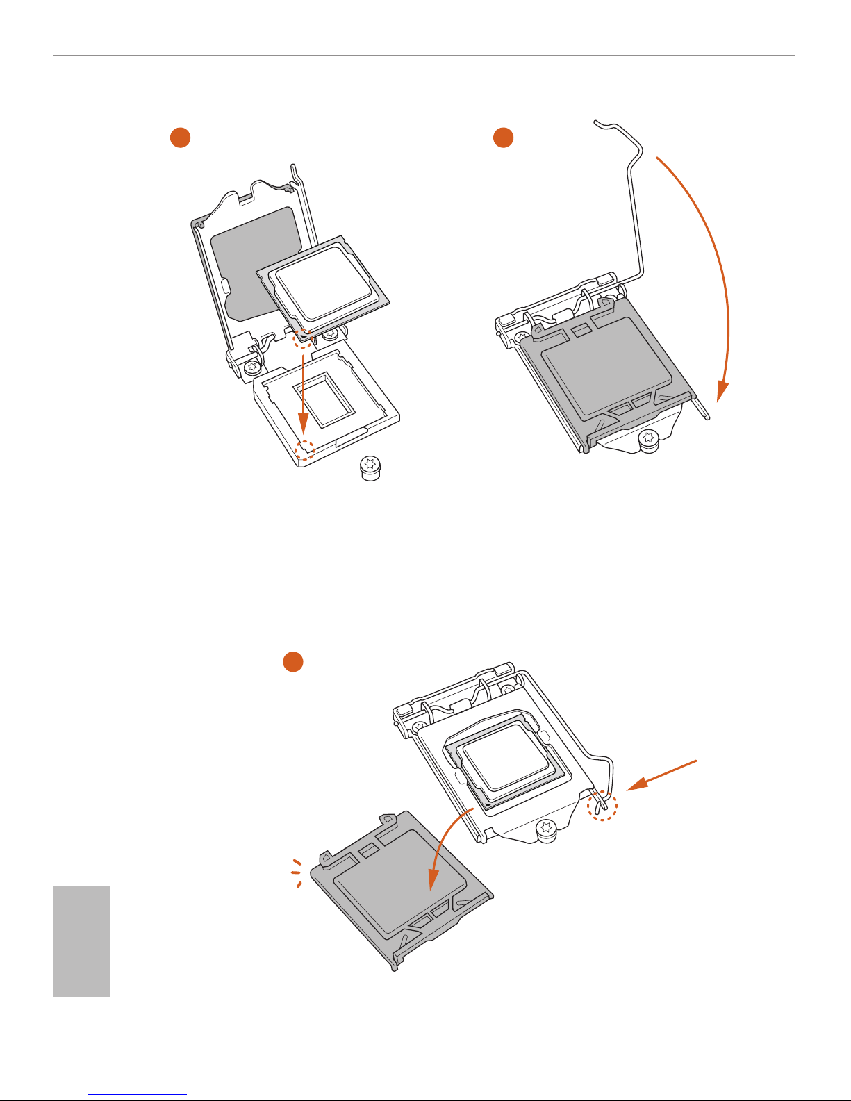
2.1 Installing the CPU
1. Before you insert the 1151-Pin CPU into the socket, please check if the PnP cap
is on the socket, if the CPU surface is unclean, or if there are any bent pins in the
socket. Do not force to insert the CPU into the socket if above situation is found.
Otherwise, the CPU will be seriously damaged.
2. Unplug all power cables before installing the CPU.
1
2
A
B
12
English
4
5
3
13
English
Z170 Pro4S
Please save and replace the cover if the processor is removed. e cover must be
placed if you wish to return the motherboard for aer service.
14
English
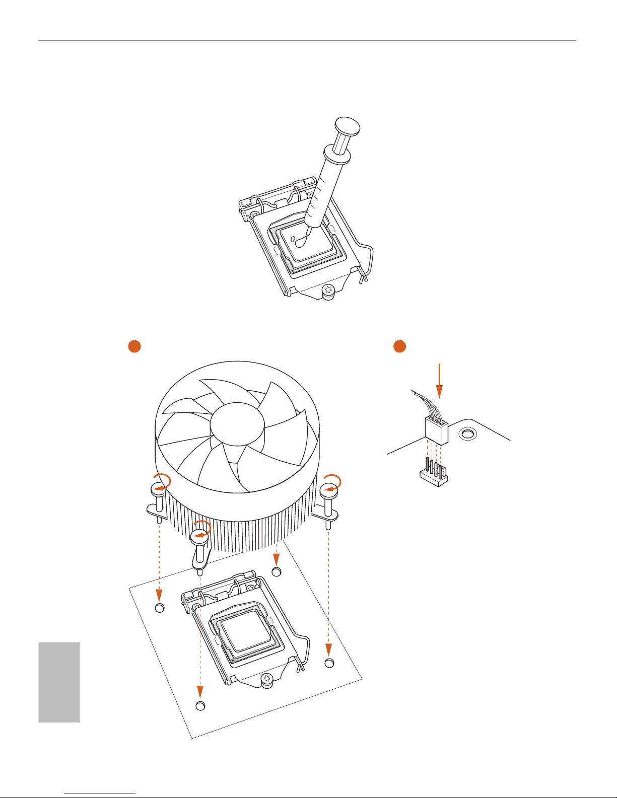
2.2 Installing the CPU Fan and Heatsink
1 2
CPU_
FAN
15
English
Z170 Pro4S
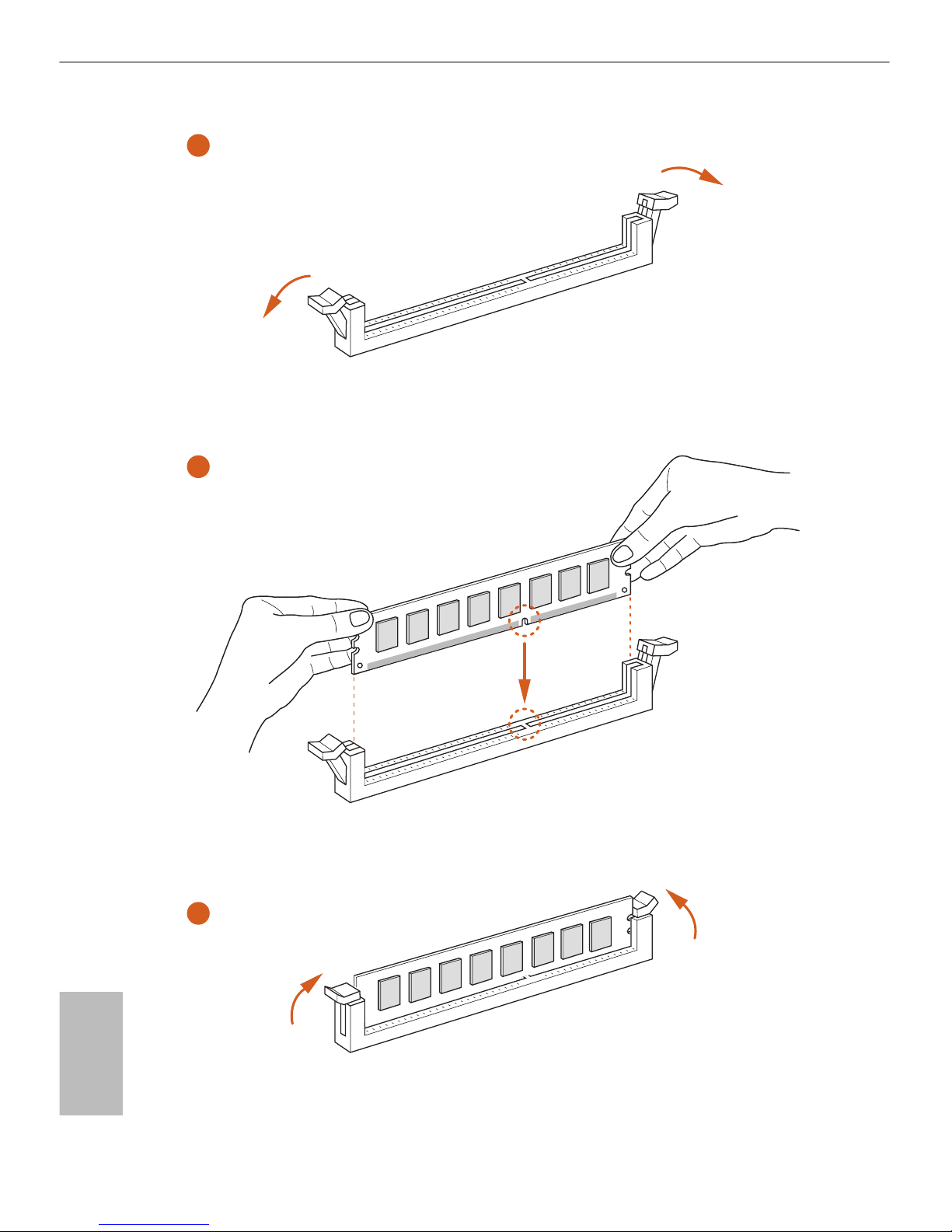
2.3 Installing Memory Modules (DIMM)
is motherboard provides four 288-pin DDR4 (Double Data Rate 4) DIMM slots,
and supports Dual Channel Memory Technology.
Dual Channel Memory Conguration
e DIMM only ts in one correct orientation. It will cause permanent damage to
the motherboard and the DIMM if you force the DIMM into the slot at incorrect
orientation.
Priority DDR4_A1 DDR4_A2 DDR4_B1 DDR4_B2
1 Populated Populated
2 Populated Populated
3 Populated Populated Populated Populated
1. For dual channel conguration, you always need to install identical (the same
brand, speed, size and chip-type) DDR4 DIMM pairs.
2. It is unable to activate Dual Channel Memory Technology with only one or three
memory module installed.
3. It is not allowed to install a DDR, DDR2 or DDR3 memory module into a DDR4
slot; otherwise, this motherboard and DIMM may be damaged.
16
English
1
2
3
17
English
Z170 Pro4S
2.4 Expansion Slots (PCI Express Slots)
ere are 5 PCI Express slots on the motherboard.
PCIe slots:
PCIE1 (PCIe 3.0 x1 slot) is used for PCI Express x1 lane width cards.
PCIE2 (PCIe 3.0 x16 slot) is used for PCI Express x16 lane width graphics cards.
PCIE3 (PCIe 3.0 x1 slot) is used for PCI Express x1 lane width cards.
PCIE4 (PCIe 3.0 x16 slot) is used for PCI Express x4 lane width graphics cards.
PCIE5 (PCIe 3.0 x1 slot) is used for PCI Express x1 lane width cards.
PCIe Slot Congurations
For a better thermal environment, please connect a chassis fan to the motherboard’s
chassis fan connector (CHA_FAN1, CHA_FAN2 or CHA_FAN3) when using multiple graphics cards.
Before installing an expansion card, please make sure that the power supply is
switched o or the power cord is unplugged. Please read the documentation of the
expansion card and make necessary hardware settings for the card before you start
the installation.
PCIE2 PCIE4
Single Graphics Card x16 N/A
Two Graphics Cards in
CrossFireXTM Mode
x16 x4
18
English
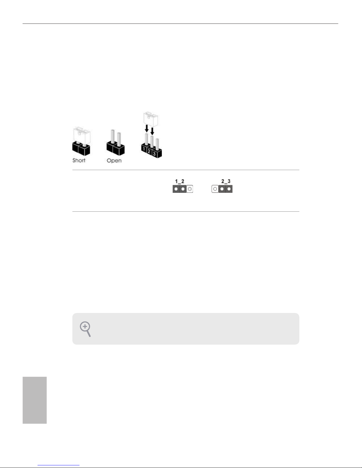
2.5 Jumpers Setup
e illustration shows how jumpers are setup. When the jumper cap is placed on
the pins, the jumper is “Short”. If no jumper cap is placed on the pins, the jumper
is “Open”. e illustration shows a 3-pin jumper whose pin1 and pin2 are “Short”
when a jumper cap is placed on these 2 pins.
Clear CMOS Jumper
(CLRMOS1)
(see p.1, No. 25)
CLRMOS1 allows you to clear the data in CMOS. To clear and reset the system
parameters to default setup, please turn o the computer and unplug the power
cord from the power supply. Aer waiting for 15 seconds, use a jumper cap to
short pin2 and pin3 on CLRMOS1 for 5 seconds. However, please do not clear the
CMOS right aer you update the BIOS. If you need to clear the CMOS when you
just nish updating the BIOS, you must boot up the system rst, and then shut it
down before you do the clear-CMOS action. Please be noted that the password,
date, time, and user default prole will be cleared only if the CMOS battery is
removed.
Clear CMOSDefault
If you clear the CMOS, the case open may be detected. Please adjust the BIOS option
“Clear Status” to clear the record of previous chassis intrusion status.
19
English
Z170 Pro4S
2.6 Onboard Headers and Connectors
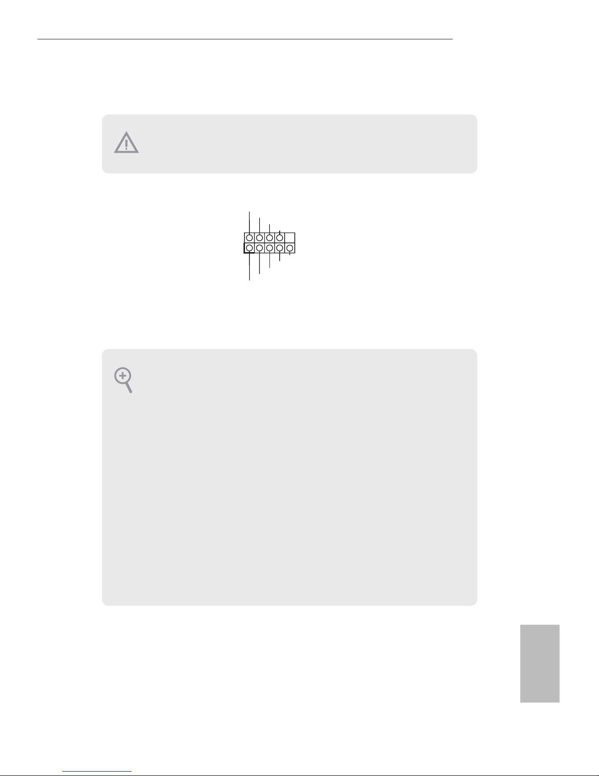
System Panel Header
(9-pin PANEL1)
(see p.1, No. 13)
Connect the power
switch, reset switch and
system status indicator on
the chassis to this header
according to the pin
assignments below. Note
the positive and negative
pins before connecting
the cables.
GND
RES ET #
PWR BT N#
PLE D-
PLE D+
GND
HDL ED -
HDL ED +
1
GND
PWRBTN (Power Switch):
Connect to the power switch on the chassis front panel. You may congure the way to
turn o your system using the power switch.
RESET (Reset Switch):
Connect to the reset switch on the chassis front panel. Press the reset switch to restart
the computer if the computer freezes and fails to perform a normal restart.
PLED (System Power LED):
Connect to the power status indicator on the chassis front panel. e LED is on when
the system is operating. e LED keeps blinking when the system is in S1/S3 sleep
state. e LED is o when the system is in S4 sleep state or powered o (S5).
HDLED (Hard Drive Activity LED):
Connect to the hard drive activity LED on the chassis front panel. e LED is on
when the hard drive is reading or writing data.
e front panel design may dier by chassis. A front panel module mainly consists
of power switch, reset switch, power LED, hard drive activity LED, speaker and etc.
When connecting your chassis front panel module to this header, make sure the wire
assignments and the pin assignments are matched correctly.
Onboard headers and connectors are NOT jumpers. Do NOT place jumper caps over
these headers and connectors. Placing jumper caps over the headers and connectors
will cause permanent damage to the motherboard.
20
English
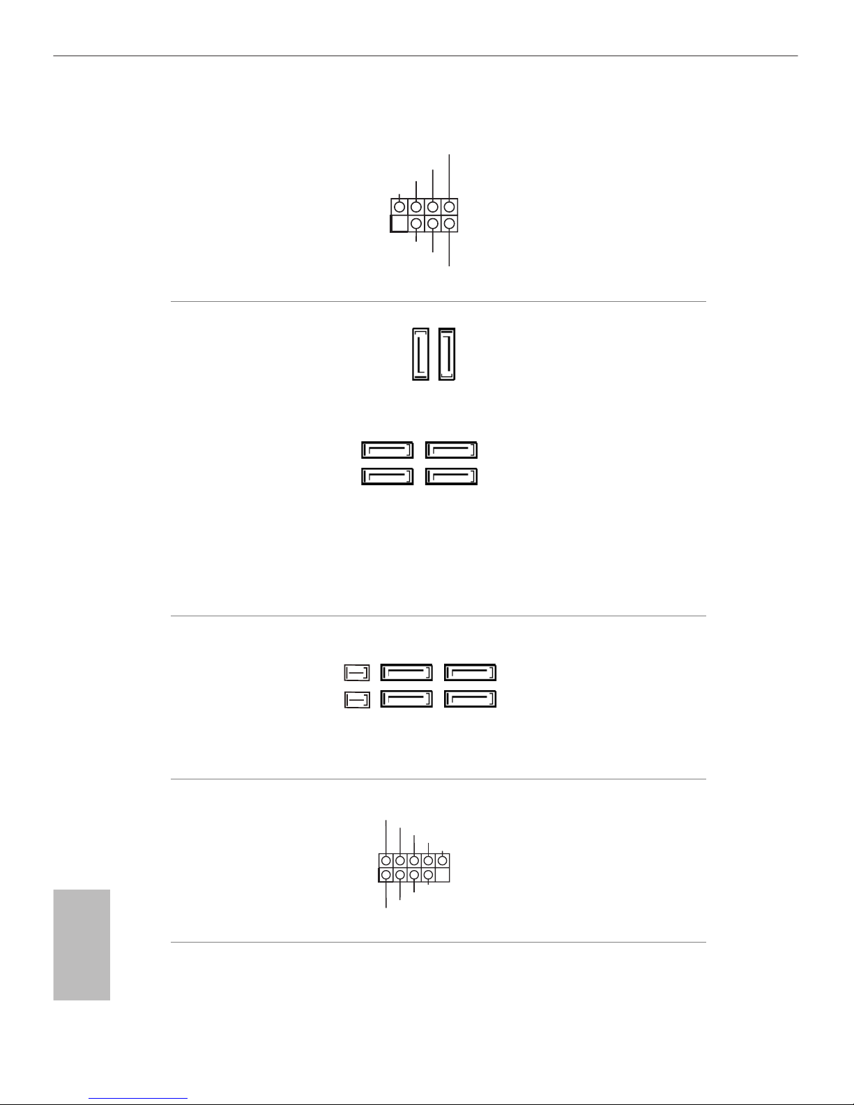
Power LED and Speaker
Header
(7-pin SPK_PLED1)
(see p.1, No. 15)
Please connect the
chassis power LED and
the chassis speaker to this
header.
Serial ATA3 Connectors
(SATA3_0:
see p.1, No. 6)
(SATA3_1:
see p.1, No. 7)
(SATA3_2:
see p.1, No. 12)
(SATA3_3:
see p.1, No. 14)
(SATA3_4:
see p.1, No. 11)
(SATA3_5:
see p.1, No. 10)
ese six SATA3
connectors support SATA
data cables for internal
storage devices with up to
6.0 Gb/s data transfer rate.
If the Ultra M.2 Socket
(M2_1) is occupied by a
SATA-type M.2 device,
SATA3_0 and SATA3_1
will be disabled.
Serial ATA Express
Connectors
(SATA_EXP0:
see p.1, No. 16)
(SATA_EXP1:
see p.1, No. 9)
Please connect either
SATA or PCIe storage
devices to these
connectors.
USB 2.0 Headers
(9-pin USB_1_2)
(see p.1, No. 20)
(9-pin USB_3_4)
(see p.1, No. 19)
ere are two headers
on this motherboard.
Each USB 2.0 header can
support two ports.
1
+5V
DUMMY
PLED+
PLED+
PLED-
DUMMY
SPEAKER
DUM MY
GND
GND
P+
P-
USB _P WR
P+
P-
USB _P WR
1
SATA3_1
SATA3_0
SATA3_5
SATA3_3
SATA3_4
SATA3_2
SATA_EXP1
SATA3_5
SATA3_3
SATA3_4
SATA3_2
SATA_EXP0
21
English
Z170 Pro4S
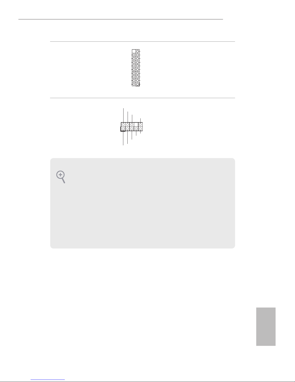
USB 3.0 Header
(19-pin USB3_7_8)
(see p.1, No. 5)
Besides six USB 3.0 ports
on the I/O panel, there
is one header on this
motherboard. Each USB
3.0 header can support
two ports.
Front Panel Audio Header
(9-pin HD_AUDIO1)
(see p.1, No. 24)
is header is for
connecting audio devices
to the front audio panel.
1
Int A_PB _D+
Dum my
Int A_PB _D-
GND
Int A_PB _SS TX+
GND
Int A_PB _SS TX-
Int A_PB _SS RX+
Int A_PB _SS RX-
Vbu sVbu s
Vbu s
Int A_PA_ SSRX -
Int A_PA_ SSRX +
GND
Int A_PA_ SSTX -
Int A_PA_ SSTX +
GND
Int A_PA_ D-
Int A_PA_ D+
J_S EN SE
OUT 2_ L
1
MIC _R ET
PRE SE NCE #
GND
OUT 2_ R
MIC 2_ R
MIC 2_ L
OUT _R ET
1. High Denition Audio supports Jack Sensing, but the panel wire on the chassis
must support HDA to function correctly. Please follow the instructions in our
manual and chassis manual to install your system.
2. If you use an AC’97 audio panel, please install it to the front panel audio header by
the steps below:
A. Connect Mic_IN (MIC) to MIC2_L.
B. Connect Audio_R (RIN) to OUT2_R and Audio_ L (LIN) to OUT2_L.
C. Connect Ground (GND) to Ground (GND).
D. MIC_ RET and OUT_RET are for the HD audio panel only. You don’t need to
connect them for the AC’97 audio panel.
E. To activate the front mic, go to the “FrontMic” Tab in the Realtek Control panel
and adjust “Recording Volume”.
22
English
Chassis Fan Connectors
(4-pin CHA_FAN1)
(see p.1, No. 18)
(4-pin CHA_FAN2)
(see p.1, No. 17)
(4-pin CHA_FAN3)
(see p.1, No. 26)
Please connect fan cables
to the fan connectors and
match the black wire to
the ground pin.
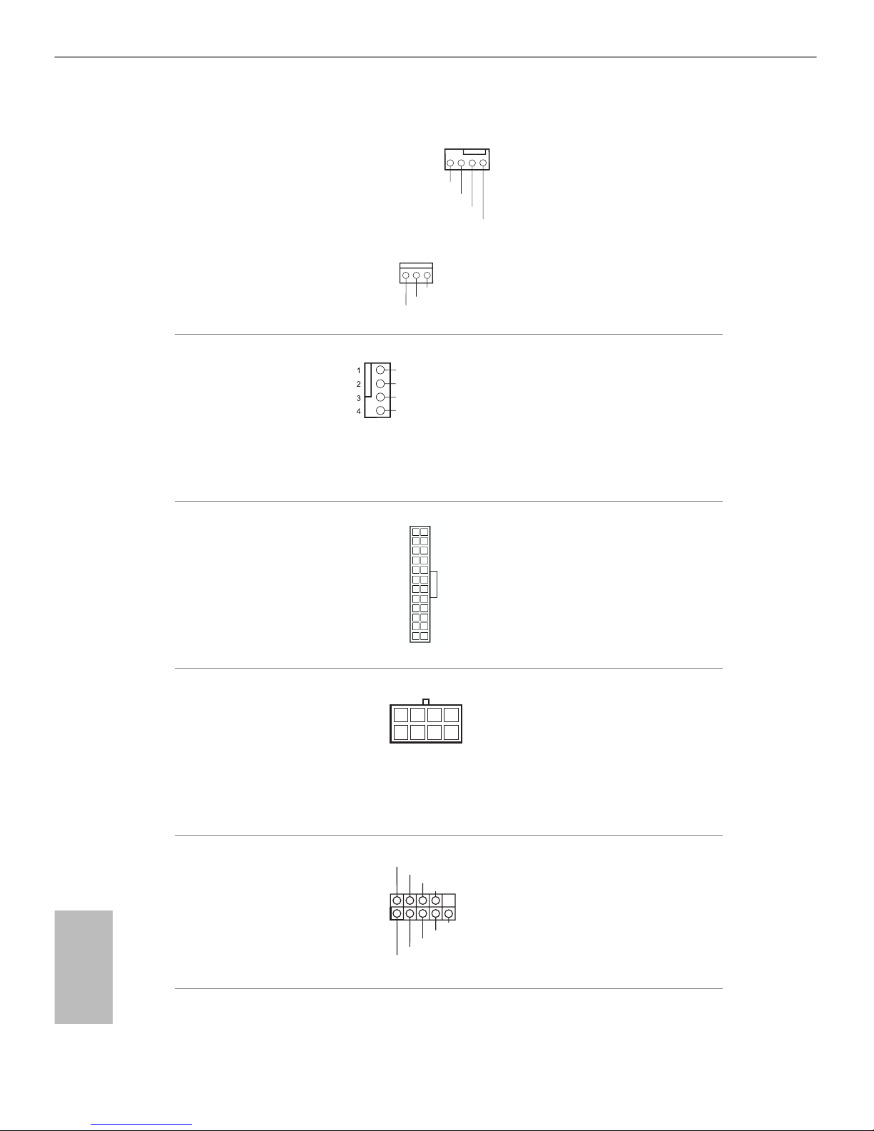
CPU Fan Connector
(4-pin CPU_FAN1)
(see p.1, No. 8)
is motherboard provides a 4-Pin CPU fan
(Quiet Fan) connector.
If you plan to connect a
3-Pin CPU fan, please
connect it to Pin 1-3.
ATX Power Connector
(24-pin ATXPWR1)
(see p.1, No. 4)
is motherboard provides a 24-pin ATX power
connector. To use a 20-pin
ATX power supply, please
plug it along Pin 1 and Pin
13.
ATX 12V Power
Connector
(8-pin ATX12V1)
(see p.1, No. 1)
is motherboard provides an 8-pin ATX 12V
power connector. To use a
4-pin ATX power supply,
please plug it along Pin 1
and Pin 5.
Serial Port Header
(9-pin COM1)
(see p.1, No. 23)
is COM1 header
supports a serial port
module.
12
1
24
13
5
1
8
CCT S#1
RRT S#1
DDS R#1
DDT R#1
RRX D1
GND
TTX D1
DDC D#1
1
RRI #1
GND
FAN_ VOLTA GE_ CON TRO L
FAN_ SPE ED
FAN_ SPE ED _ CO NTR OL
GN D
FAN _V OLT AG E
CHA _F AN_ SP EED
FAN _S PEE D_ CON TRO L
GND
FAN_ VOLTAG E
FAN_ SPE ED
23
English
Z170 Pro4S
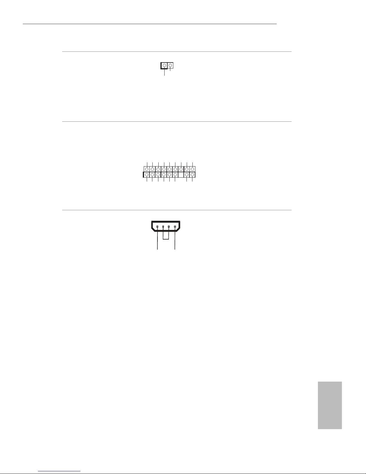
Chassis Intrusion Header
(2-pin CI1)
(see p.1, No. 21)
is motherboard supports
CASE OPEN detection feature
that detects if the chassis cove
has been removed. This feature
requires a chassis with chassis
intrusion detection design.
TPM Header
(17-pin TPMS1)
(see p.1, No. 22)
is connector supports Trusted
Platform Module (TPM) system,
which can securely store keys,
digital certicates, passwords,
and data. A TPM system also
helps enhance network security,
protects digital identities, and
ensures platform integrity.
PCIe Power Connector
(4-pin PCIE_PWR1)
(see p.1, No. 27)
Please connect a 4 pin molex
power cable to this connector
when more than three graphics
cards are installed.
1
GND
SMB _D ATA _MA IN
LAD 2
LAD 1
GND
S_P WR DWN #
SER IR Q#
GND
PCI CL K
PCI RS T#
LAD 3
+3V
LAD 0
+3V SB
GND
FRA ME
SMB _C LK_ MAI N
+1 2V DE TECT
GN D
1
Sig na l
GND
24
English
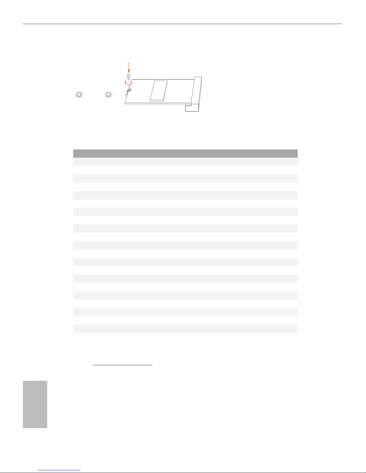
2.7 M.2_SSD (NGFF) Module Installation Guide
The M.2, also known as the Next Generation Form Factor (NGFF), is a small size and
versatile card edge connector that aims to replace mPCIe and mSATA. The Ultra M.2
Socket (M2_1) supports M.2 PCI Express module up to Gen3 x4 (32 Gb/s).
Please be noted that if the Ultra M.2 Socket (M2_1) is occupied by a SATA-type M.2
device, SATA3_0 and SATA3_1 will be disabled.
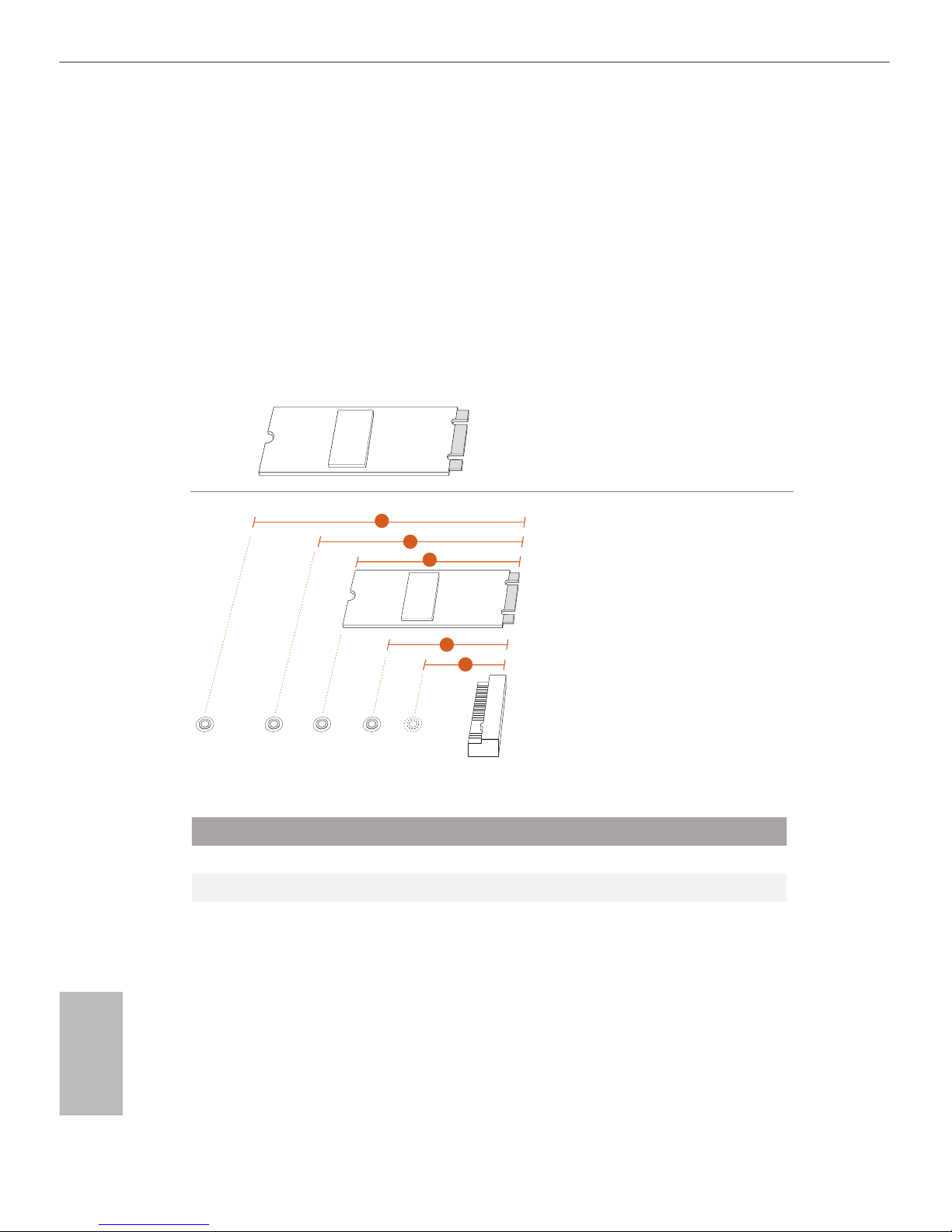
Installing the M.2_SSD (NGFF) Module
Step 1
Prepare a M.2_SSD (NGFF) module
and the screw.
3
2
4
5
BCDE
A
1
Step 2
Depending on the PCB type and
length of your M.2_SSD (NGFF)
module, nd the corresponding nut
location to be used.
No. 1 2 3 4 5
Nut Location A B C D E
PCB Length 3cm 4.2cm 6cm 8cm 11cm
Module Type Type2230 Type 2242 Type2260 Type 2280 Type 22110
25
English
Z170 Pro4S
BCDE
A
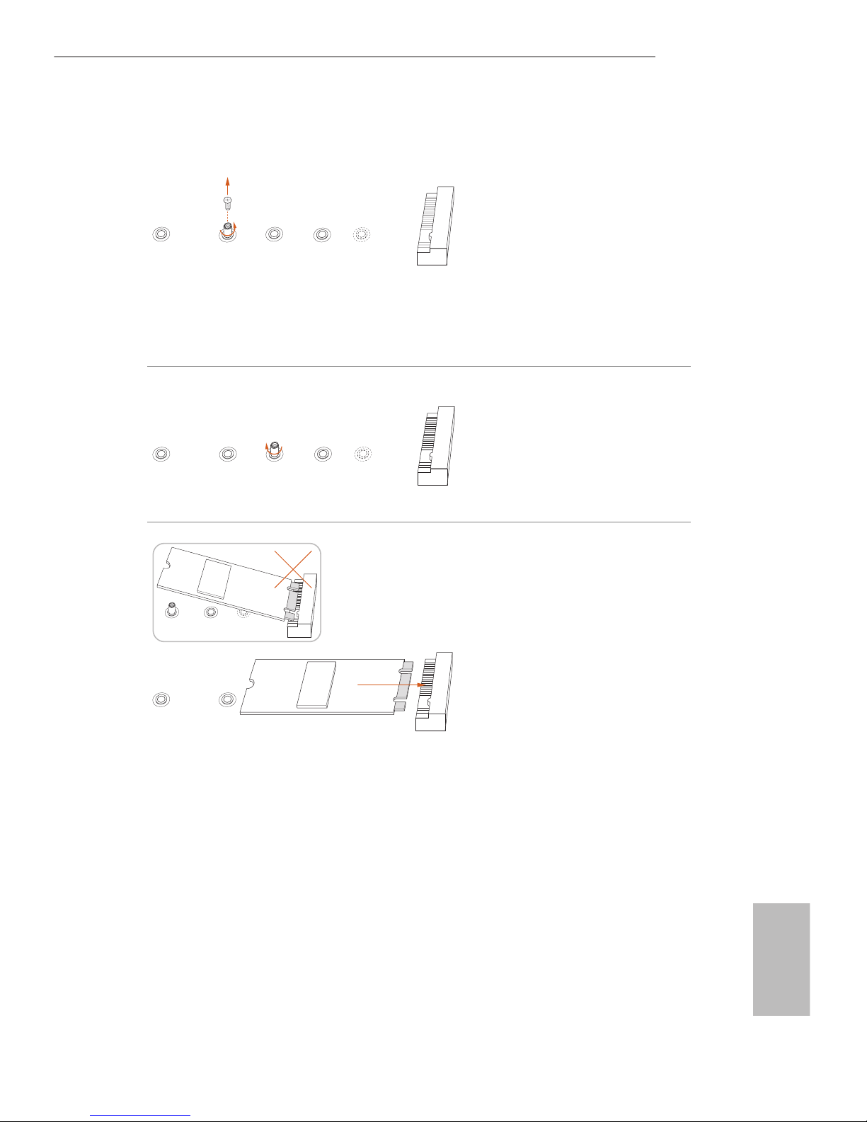
Step 3
Move the stando based on the
module type and length.
e stando is placed at the nut
location D by default. Skip Step 3
and 4 and go straight to Step 5 if you
are going to use the default nut.
Otherwise, release the stando by
hand.
BCDE
A
Step 4
Peel o the yellow protective lm on
the nut to be used. Hand tighten the
stando into the desired nut location
on the motherboard.
BC
A
ABCDE
Step 5
Align and gently insert the M.2
(NGFF) SSD module into the M.2
slot. Please be aware that the M.2
(NGFF) SSD module only ts in one
orientation.
26
English
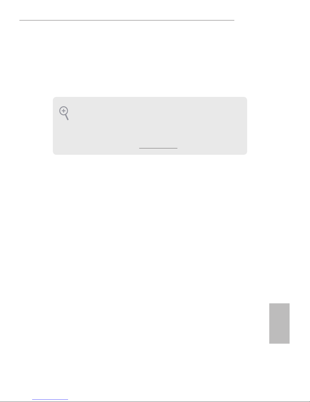
NUT1NUT2DE
Step 6
Tighten the screw with a screwdriver
to secure the module into place.
Please do not overtighten the screw
as this might damage the module.
M.2_SSD (NGFF) Module Support List
For the latest updates of M.2_SSD (NFGG) module support list, please visit our website for
details: http://www.asrock.com
Vendor Size Interface Length P/N
ADATA 128GB SATA3 2280 AXNS381E-128GM-B
ADATA 256GB SATA3 2280 AXNS381E-256GM-B
ADATA 32GB SATA3 2230 AXNS330E-32GM-B
Crucial 120GB SATA3 2280 CT120M500SSD4
Crucial 240GB SATA3 2280 CT240M500SSD4
Intel 80GB SATA3 2280 Intel SSDSCKGW080A401/80G
Kingston 120GB SATA3 2280 SM2280S3
Kingston 480GB PCIe2 x4 2280 SH2280S3/480G
Plextor 256GB PCIe 2280 PX-G256M6e
Plextor 512GB PCIe 2280 PX-G512M6e
Samsung 256GB PCIe3 x4 2280 SM951 (MZHPV256HDGL)
Samsung 512GB PCIe3 x4 2280 SM951 (MZHPV512HDGL)
Samsung 512GB PCIe x4 2280 XP941-512G (MZHPU512HCGL)
SanDisk 128GB PCIe 2260 SD6PP4M-128G
SanDisk 256GB PCIe 2260 SD6PP4M-256G
Team 128GB SATA3 2242 TM4PS4128GMC105
Team 128GB SATA3 2280 TM8PS4128GMC105
Team 256GB SATA3 2280 TM8PS4256GMC105
Team 256GB SATA3 2242 TM4PS4256GMC105
Transcend 256GB SATA3 2242 TS256GMTS400
Transcend 512GB SATA3 2280 TS512GMTS800
Transcend 512GB SATA3 2260 TS512GMTS600
27
Deutsch
Z170 Pro4S
1 Einleitung
Vielen Dank, dass Sie sich für das Z170 Pro4S von ASRock entschieden haben – ein
zuverlässiges Motherboard, das konsequent unter der strengen Qualitätskontrolle von
ASRock hergestellt wurde. Es liefert ausgezeichnete Leistung mit robustem Design,
das ASRocks Streben nach Qualität und Beständigkeit erfüllt.
1.1 Lieferumfang
•
ASRock Z170 Pro4S-Motherboard (ATX-Formfaktor)
•
ASRock Z170 Pro4S-Schnellinstallationsanleitung
•
ASRock Z170 Pro4S-Support-CD
•
2 x Serial-ATA- (SATA) Datenkabel (optional)
•
1 x E/A-Blendenabschirmung
•
1 x Schraube für M.2-Sockel
Da die technischen Daten des Motherboards sowie die BIOS-Soware aktualisiert
werden können, kann der Inhalt dieser Dokumentation ohne Ankündigung geändert
werden. Falls diese Dokumentation irgendwelchen Änderungen unterliegt, wird die aktualisierte Version ohne weitere Hinweise auf der ASRock-Webseite zur Verfügung gestellt.
Sollten Sie technische Hilfe in Bezug auf dieses Motherboard benötigen, erhalten Sie auf
unserer Webseite spezischen Informationen über das von Ihnen verwendete Modell.
Auch nden Sie eine aktuelle Liste unterstützter VGA-Karten und Prozessoren auf der
ASRock-Webseite: ASRock-Website http://www.asrock.com.

28
Deutsch
1.2 Technische Daten
Plattform
•
ATX-Formfaktor
•
Solides Kondensatordesign
•
Leiterplatte mit hochdichtem Glasgewebe
Prozessor
•
Unterstützt die Prozessoren Intel® CoreTM i7/i5/i3/Pentium®/
Celeron® der 6. Generation (Sockel 1151)
•
Digipower-Design
•
10-Leistungsphasendesign
•
Unterstützt Intel® Turbo Boost 2.0-Technologie
•
Unterstützt CPUs mit freiem Multiplikator der Intel® K-Serie
•
Unterstützt ASRock BCLK-Übertaktung (voller Bereich)
Chipsatz
•
Intel® Z170
Speicher
•
Dualkanal-DDR4-Speichertechnologie
•
4 x DDR4-DIMM-Steckplätze
•
Unterstützt DDR4 3200+(OC)*/2933(OC)/2800(OC)/2400
(OC)/2133 non-ECC, ungepuerter Speicher
* Weitere Informationen nden Sie in der
Speicherkompatibilitätsliste auf der ASRock-Webseite.
(http://www.asrock.com/)
•
Systemspeicher, max. Kapazität: 64GB
•
Unterstützt Intel® Extreme Memory Prole (XMP) 2.0
Erweiterungssteckplatz
•
2 x PCI-Express 3.0-x16-Steckplätze (PCIE2:x16-Modus;
PCIE4:x4-Modus)
•
3 x PCI-Express 3.0-x1-Steckplätze (Flexible PCIe)
•
Unterstützt AMD Quad CrossFireXTM und CrossFireXTM
Grakkarte
•
Integrierte Intel® HD Graphics-Visualisierung und VGA-
Ausgänge können nur mit Prozessoren unterstützt werden, die
GPU-integriert sind.
•
Unterstützt integrierte Intel® HD Graphics-Visualisierung:
Intel® Quick Sync Video mit AVC, MVC (S3D) und MPEG-
2 Full HW Encode1, Intel® InTruTM 3D, Intel® Clear Video HD
Technology, Intel® InsiderTM, Intel® HD Graphics 510/530
•
Pixel Shader 5.0, DirectX 12
•
Max. geteilter Speicher: 1792 MB
 Loading...