

N3150TM-ITXN3150TM-ITX
N3150TM-ITXN3150TM-ITX

Version 1.1
Published August 2015
Copyright©2015 ASRock INC. All rights reserved.
Copyright Notice:
No part of this documentation may be reproduced, transcribed, transmitted, or
translated in any language, in any form or by any means, except duplication of
documentation by the purchaser for backup purpose, without written consent of
ASRock Inc.
Products and corporate names appearing in this documentation may or may not
be registered trademarks or copyrights of their respective companies, and are used
only for identication or explanation and to the owners’ benet, without intent to
infringe.
Disclaimer:
Specications and information contained in this documentation are furnished for
informational use only and subject to change without notice, and should not be
constructed as a commitment by ASRock. ASRock assumes no responsibility for
any errors or omissions that may appear in this documentation.
With respect to the contents of this documentation, ASRock does not provide
warranty of any kind, either expressed or implied, including but not limited to
the implied warranties or conditions of merchantability or tness for a particular
purpose.
In no event shall ASRock, its directors, ocers, employees, or agents be liable for
any indirect, special, incidental, or consequential damages (including damages for
loss of prots, loss of business, loss of data, interruption of business and the like),
even if ASRock has been advised of the possibility of such damages arising from any
defect or error in the documentation or product.
is device complies with Part 15 of the FCC Rules. Operation is subject to the following
two conditions:
(1) this device may not cause harmful interference, and
(2) this device must accept any interference received, including interference that
may cause undesired operation.
CALIFORNIA, USA ONLY
e Lithium battery adopted on this motherboard contains Perchlorate, a toxic substance
controlled in Perchlorate Best Management Practices (BMP) regulations passed by the
California Legislature. When you discard the Lithium battery in California, USA, please
follow the related regulations in advance.
“Perchlorate Material-special handling may apply, see www.dtsc.ca.gov/hazardouswaste/
perchlorate”
ASRock Website: http://www.asrock.com

e terms HDMI™ and HDMI High-Denition Multimedia Interface, and the HDMI
logo are trademarks or registered trademarks of HDMI Licensing LLC in the United
States and other countries.

Contents
Chapter 1 Introduction 1
1.1 Package Contents 1
1.2 Specications 2
1.3 Motherboard Layout 5
1.4 I/O Panel 7
Chapter 2 Installation 8
2.1 Installing Memory Modules (SO-DIMM) 9
2.2 Expansion Slots (PCI Express Slots) 11
2.3 Jumpers Setup 12
2.4 Onboard Headers and Connectors 13
Chapter 3 Software and Utilities Operation 19
3.1 Installing Drivers 19
3.2 ASRock Live Update & APP Shop 20
3.2.1 UI Overview 20
3.2.2 Apps 21
3.2.3 BIOS & Drivers 24
3.2.4 Setting 25
Chapter 4 UEFI SETUP UTILITY 29
4.1 Introduction 29
4.1.1 UEFI Menu Bar 29
4.1.2 Navigation Keys 30
4.2 Main Screen 31

4.3 Advanced Screen 32
4.3.1 CPU Conguration 33
4.3.2 Chipset Conguration 34
4.3.3 Storage Conguration 36
4.3.4 IntelRMT Conguration 38
4.3.5 Super IO Conguration 39
4.3.6 ACPI Conguration 40
4.3.7 USB Conguration 42
4.3.8 Trusted Computing 43
4.4 Tools 44
4.5 Hardware Health Event Monitoring Screen 46
4.6 Security Screen 47
4.7 Boot Screen 48
4.8 Exit Screen 51

English
N3150TM-ITX
Chapter 1 Introduction
ank you for purchasing ASRock N3150TM-ITX motherboard, a reliable
motherboard produced under ASRock’s consistently stringent quality control.
It delivers excellent performance with robust design conforming to ASRock’s
commitment to quality and endurance.
In this manual, Chapter 1 and 2 contains the introduction of the motherboard
and step-by-step installation guides. Chapter 3 contains the operation guide of the
soware and utilities. Chapter 4 contains the conguration guide of the BIOS setup.
Becau se the motherboard specications and the BIOS so ware might be updated, the
content of this documentation will be subject to change without notice. In case any
modications of this documentation occur, the updated version will be available on
ASRock’s website w ithout further notic e. If you require technical support related to
this motherboard, please visit our website for specic information about the model
you are using. You may nd the latest VGA cards and CPU support list on ASRock’s
website a s well. ASRock website http://www.asrock.com.
1.1 Package Contents
ASRock N3150TM-ITX Motherboard (in Mini-ITX Form Factor)
•
ASRock N3150TM-ITX Quick Installation Guide
•
ASRock N3150TM-ITX Support CD
•
2 x Serial ATA (SATA) Data Cables (Optional)
•
1 x SATA 1 to 2 Power Cable (Opt ional)
•
2 x I/O Panel Shields
•
1 x WiFi Module Screw
•
1

English
1.2 Specications
Platform
CPU
Memory
Expansion
Slot
•
•
•
•
•
•
•
•
* If only one SO-DIMM module is installed, please install it into
DDR3_A1.
•
•
* Due to the power limitation and PCIe bandwidth (x1), the VGA
card is not supported.
in Mini-ITX Form Factor
Solid Capacitor design
High Density Glass Fabric PCB
Intel® Quad-Core Processor N3150 (up to 2.08 GHz)
Dual Channel DDR3/DDR3L Memory Technology
2 x DDR3/DDR3L SO-DIMM Slots
Supports DDR3/DDR3L 1600/1066 non-ECC, un-buered
memory
Max. capacity of system memory: 16GB
(see CAUTION)
1 x PCI Express 2.0 x1 Slot
1 x Half-size Mini-PCI Express Slot
2
Graphics
•
•
•
•
•
•
•
•
•
•
•
th
Intel® 8
generation (Gen 8) graphics: up to 12 EUs inside
DirectX 11.1, Pixel Shader 5.0
ree graphics output options: D-Sub, HDMI and LVDS
Supports Triple Monitor
Supports HDMI with max. resolution up to 2560x1600 @
60Hz
Supports D-Sub with max. resolution up to 1920x1200 @
60Hz
Supports LVDS with max. resolution up to 1920x1200 @
60Hz
Supports Auto Lip Sync, xvYCC and HBR (High Bit Rate
Audio) with HDMI Port (Compliant HDMI monitor is
required)
Supports HW Accelerated Decoders: H.264 @ level 5.2,
H.265/HEVC @ level 5 (GPU accelerated), JPEG, VP8
Supports HDCP with HDMI Port
Supports Full HD 1080p Blu-ray (BD) playback with HDMI
Port

English
N3150TM-ITX
Audio
LAN
Rear Panel
I/O
7.1 CH HD Audio with Content Protection (Realtek ALC892
•
Audio Codec)
* To congure 7.1 CH HD Audio, it is required to use an HD
front panel audio module and enable the multi-channel audio
feature through the audio driver.
Premium Blu-ray Audio support
•
Supports Surge Protection (ASRock Full Spike Protection)
•
ELNA Audio Caps
•
PCIE x1 Gigabit LAN 10/100/1000 Mb/s
•
Realtek RTL8111GR
•
Su ppor t s Wa ke- O n-WA N
•
Supports Wake-On-LAN
•
Supports Lightning/ESD Protection (ASRock Full Spike
•
Protection)
Supports LAN Cable Detection
•
Supports Energy Ecient Ethernet 802.3az
•
Supports PXE
•
1 x DC Jack (Compatible with the 19V power adapter)
•
1 x D-Sub Port
•
1 x HDMI Port
•
4 x USB 3.0 Ports (Supports ESD Protection (ASRock Full
•
Spike Protection))
1 x RJ-45 LAN Port with LED (ACT/LINK LED and SPEED
•
LED)
HD Audio Jacks: Microphone / Front Speaker (Supports
•
SPDIF Optical)
Storage
Connector
2 x SATA3 6.0 Gb/s Connectors, support NCQ, AHCI and
•
Hot Plug
1 x Backlight Power Selection Jumper
•
1 x Panel Power Selection Jumper
•
1 x Backlight Control Header
•
1 x Digital Input / Output Pin Header
•
1 x Digital Input / Output Power Selection Jumper
•
1 x Home eater PC Header
•
1 x Monitor Switch Header
•
1 x Digital MIC Header
•
1 x 3W Audio AMP Output Wafer Header
•
1 x LVDS Connector
•
1 x CIR Header
•
3

English
BIOS
Feature
Hardware
Monitor
1 x COM Port Header
•
1 x Power LED Header
•
1 x TPM Header
•
1 x CPU Fan Connector (4-pin)
•
1 x Chassis Fan Connector (4-pin)
•
1 x SATA Power Connector
•
1 x Internal Power Header
•
1 x Front Panel Audio Connector
•
1 x Analog Surround Audio Connector
•
3 x USB 2.0 Headers (Support 5 USB 2.0 ports) (Supports ESD
•
Protection (ASRock Full Spike Protection))
1 x USB 3.0 Header by Etron EJ188 (Supports 2 USB 3.0 ports)
•
(Supports ESD Protection (ASRock Full Spike Protection))
64Mb AMI UEFI Legal BIOS with GUI support
•
Supports Plug and Play
•
ACPI 1.1 compliant wake up events
•
Supports jumperfree
•
SMBIOS 2.3.1 support
•
CPU/Chassis temperature sensing
•
CPU/Chassis Fan Tachometer
•
CPU/Chassis Quiet Fan (Auto adjust chassis fan speed by
•
CPU temperature)
CPU/Chassis Fan multi-speed control
•
Voltage monitoring: +12V, +5V, +3.3V, CPU Vcore
•
4
Microso® Windows® 10 64-bit / 8.1 64-bit / 7 64-bit
OS
•
* To install Windows® 7 64-bit OS, a modied installation disk
with xHCI drivers packed into the ISO le is required. Please
refer to page 26 for more detailed instructions.
* For the updated Windows® 10 driver, please visit ASRock's
website for details: http://www.asrock.com
FCC, CE, WHQL
Certications
* For detailed product information, please visit our website: http://www.asrock .com
Due to limitation, the ac tual memory size may be less th an 4GB for the reservation
for system usage under Windows® 32-bit operating systems. Windows® 64 -bit operating systems do not have such limitations. You can use ASRock XFast R AM to utilize
the memory that Windows® cannot u se.
•
ErP/EuP ready (ErP/EuP ready power supply is required)
•
English
N3150TM-ITX
1.3 Motherboard Layout
17
PCIE1
134756 91114810
12
13
CMOS
Battery
RoHS
Front USB 3.0
15
16
18
19
20
64Mb
BIOS
MINI_PCIE1
LAN
USB3_4_5
26 25
29
212223
24
SATA3_2
SATA3_1
1
CIR1
HDLED RESET
PLED PWRBTN
PANEL1
1
LVDS 1
BKT_PWR1
JGPIO_PWR1
1
PNL_PWR1
11 1
PLED1
CPU_FAN1
CHA_FAN1
BLT_VOL1
1
COM1
1
USB7_8
1
TPMS1
CLRCMOS1
1
1
HD_AUDIO2
1
SPEAKER1
1
1
HD_AUDIO1
JGPIO
1
DMIC1
1
1
HTPC1
Front
Speaker
Mic In
USB 3.0
T: USB2
B: USB3
USB 3.0
T: USB0
B: USB1
DC Jack
HDMI 1
VGA1
RJ-45
1
MONITOR_SWITCH1
1
1
USB4_5
USB6
2
ATX19V_IN1
DDR 3_A1
28
27
30
SATA_POW1
DDR 3_B1
AUDIO
N3150TM-ITX
5

English
No. Description
1 SATA Power Connector (SATA_POW1)
2 USB 2.0 Header (USB6)
3 SATA3 Connector (SATA3_2)
4 SATA3 Connector (SATA3_1)
5 Monitor Switch Header (MONITOR_SWITCH1)
6 USB 2.0 Header (USB4_5)
7 CPU Fan Connector (CPU_FAN1)
8 USB 3.0 Header (USB3_4 _5)
9 Chassis Fan Connector (CHA_FAN1)
10 Consumer Infrared Module Header (CIR1)
11 Power LED Header (PLED1)
12 Backlight Power Jumper (BKT_PWR1)
13 System Panel Header (PANEL1)
14 Panel Power Jumper (PNL_PWR1)
15 LVDS Connector (LVDS1)
16 Backlight Control Header (BLT_VOL1)
17 COM Port Header (COM1)
18 USB 2.0 Header (USB7_8)
19 TPM Header (TPMS1)
20 Clear CMOS Jumper (CLRCMOS1)
21 204-pin DDR3 SO-DIMM Slots (DDR3_B1)
22 Digital Input / Output Power Selection Jumper (JGPIO_PWR1)
23 Digital Input / Output Pin Header (JGPIO)
24 Home eater PC Header (HTPC1)
25 Front Panel Audio Header (HD_AUDIO1)
26 Digital MIC Header (DMIC1)
27 3W Audio AMP Output Wafer Header (SPEAKER1)
28 Analog Surround Audio Header (HD_AUDIO2)
29 204-pin DDR3 SO-DIMM Slots (DDR3_A1)
30 Internal Power Header (ATX19V_IN1)
6
English
N3150TM-ITX
1.4 I/O Panel
8762 5431
No. Description No. Description
1 DC Jack* 5 LAN RJ-45 Port**
2 USB 3.0 Ports (USB3_01) 6 USB 3.0 Ports (USB3_23)
3 D-Sub Port 7 Microphone (Pink)
4 HDMI Port 8 Front Speaker (Lime)
* Please use a 19V power adapter for the DC jack . is jack acce pts dual barrel plugs w ith an inner diameter of
5.1 mm and an outer diameter of 7.4 mm, where the inner contact is +19 (±10%) VDC and the shell is GN D.
DELTA DELTA-ADP-150TB-150W/19V
HP HP-TBC-BA52-150W/19V
FSP FSP-FSP150-ABAN1-150W/19V
** ere are two LEDs on each LA N port. Please refer to the tabl e below for the LAN port LED indications.
ACT/LINK LED
SPEED LED
LAN Por t
Activity / Link LED Speed LED
Status Description Status Description
O No Link O 10Mbps connection
Blinking Data Activit y O 100Mbps connection
On Link Orange 1Gbps connection
7

English
Chapter 2 Installation
is is a in Mini-ITX form factor motherboard. Before you install the
motherboard, study the conguration of your chassis to ensure that the
motherboard ts into it.
Pre-installation Precautions
Take note of the following precautions before you install motherboard components
or change any motherboard settings.
Make sure to unplug the power cord before installing or removing the motherboard.
•
Failure to do so may cause physical injuries to you and damages to motherboard
components.
In order to avoid damage from static electricity to the motherboard’s components,
•
NEVER place your motherboard directly on a carpet. Also remember to use a grounded
wrist strap or touch a safety grounded object before you handle the components.
Hold components by the edges and do not touch the ICs.
•
Whenever you uninstall any components, place them on a grounded anti-static pad or
•
in the bag that comes with the components.
When placing screws to secure the motherboard to the chassis, please do not over-
•
tighten the screws! Doing so may damage the motherboard.
8
English
N3150TM-ITX
2.1 Installing Memory Modules (SO-DIMM)
is motherboard provides two 204-pin DDR3/DDR3L (Double Data Rate 3) SO-
DIMM slots. If only one SO-DIMM module is insta lled, please install it into DDR3_
A1.
It is not allowed to install a DDR or DDR2 memory module into a DDR3/DDR 3L
slot; otherw ise, this motherboard and SO-DIMM may be damaged.
e SO-DIMM only t s in one correct orientation. It will cause pe rmanent damage
to the motherboard and the SO -DIMM if you force the SO-DIMM into the slot at
incorrect orientation.
9

English
1
2
10

English
N3150TM-ITX
2.2 Expansion Slots (PCI Express Slots)
ere is 1 PCI Express slot and 1 mini-PCI Express slot on the motherboard.
Before installing an expansion card, please make sure th at the power supply is
switched o or the power cord is unplugged. Please read the documentation of the
expan sion card and mak e necessary hardware settings for the card before you start the
installation.
PCIe slot:
PCIE1 (PCIe 2.0 x1 slot) is used for PCI Express cards with x1 lane width cards.
mini-PCIe slot:
MINI_PCIE1 (mini-PCIe slot) is used for WiFi module.
11
English
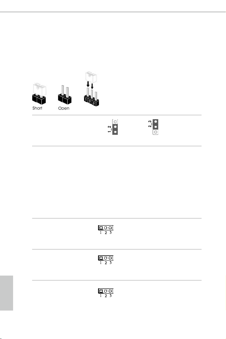
2.3 Jumpers Setup
e illustration shows how jumpers are setup. When the jumper cap is placed on
the pins, the jumper is “Short”. If no jumper cap is placed on the pins, the jumper
is “Open”. e illustration shows a 3-pin jumper whose pin1 and pin2 are “Short”
when a jumper cap is placed on these 2 pins.
Clear CMOS Jumper
(CLRC MOS1)
(see p.5, No. 20)
CLRCMOS1 allows you to clear the data in CMOS. To clear and reset the system
parameters to default setup, please turn o the computer and unplug the power
cord from the power supply. Aer waiting for 15 seconds, use a jumper cap to
short pin2 and pin3 on CLRCMOS1 for 5 seconds. However, please do not clear
the CMOS right aer you update the BIOS. If you need to clear the CMOS when
you just nish updating the BIOS, you must boot up the system rst, and then shut
it down before you do the clear-CMOS action. Please be noted that the password,
date, time, and user default prole will be cleared only if the CMOS battery is
removed.
Default
Clear CMOS
12
Backlight Power Jumper
(3-pin BKT_PWR1)
(see p.5, No. 12)
Panel Power Jumper
(3-pin PNL_PWR1)
(see p.5, No. 14)
Digital Input / Output
Power Selection Jumper
(see p.5, No. 22)
1-2 : +12V
2-3 : +19V
1-2 : +3V
2-3 : +5V
1-2 : +12V
2-3 : +5V
English
N3150TM-ITX
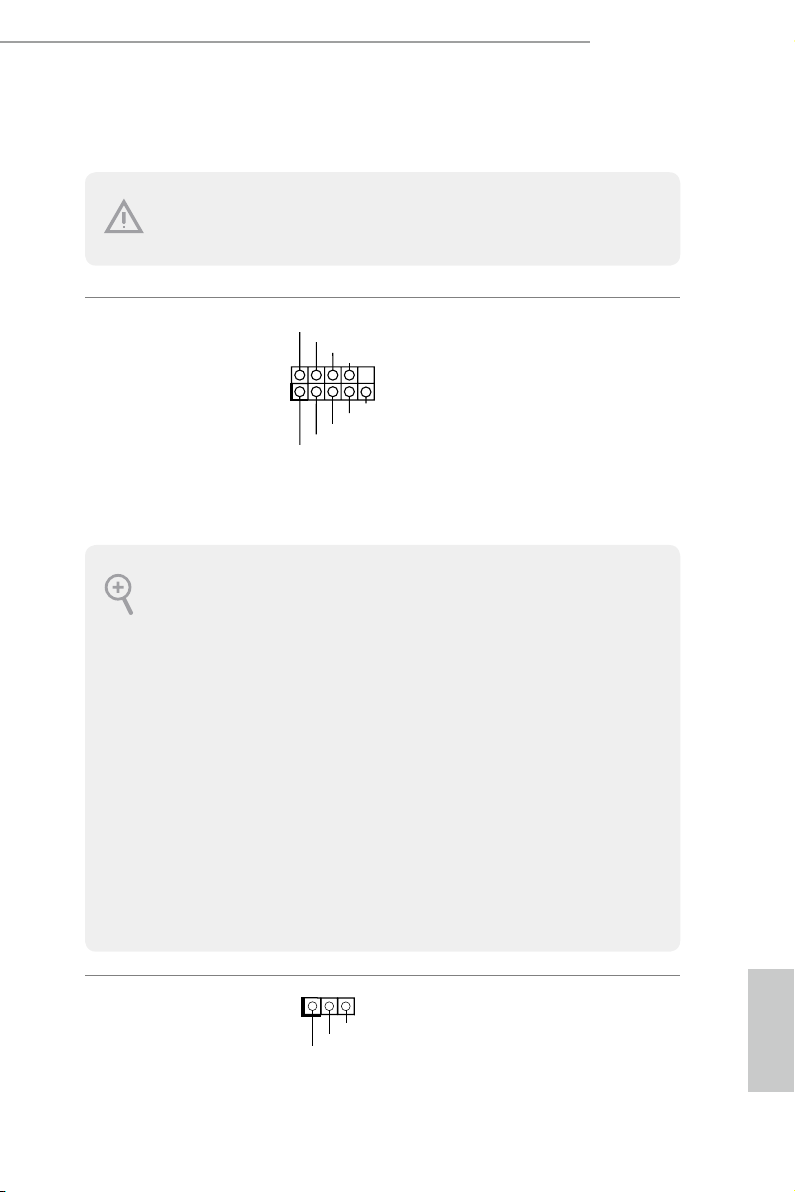
2.4 Onboard Headers and Connectors
1
1
PLED+
PLED+
PLED-
Onboard heade rs and connectors are NOT jumpers . Do NOT place jumper caps o ver the se
heade rs and connectors. Pla cing jumper caps over th e headers and connec tors will cause
permanent damage to the motherboard.
System Panel Header
(9-pi n PAN E L1)
(see p.5, No. 13)
PWRBTN (Power Sw itch):
Connec t to the power switch on the chassis front panel . You may congure the way to turn
o your system using the power sw itch.
RESET (Reset Switch):
Connec t to the reset switch on the ch assis front panel . Press the reset switch to restart the
computer if the computer freez es and fails to pe rfor m a normal restart.
PLED (Syste m Power LED):
Connec t to the power status indicator on the chassis f ront panel. e LED is on whe n the
system is operating. e LED keeps blinking when the system is in S1/S3 sleep state. e
LED is o when the system is in S4 sle ep state or powered o (S5).
HDLED (Ha rd Drive Activity LED):
Connec t to the hard drive ac tivity LED on the chassis front panel. e LED is on when the
hard drive is reading or writing d ata.
e front panel de sign may dier by chassis. A f ront panel modul e mainly consi sts of power
switch, reset switch, powe r LED, hard drive activity LED, speaker and etc. When connecting your ch assis front panel module to this header, mak e sure the w ire assignments and the
pin assignments are matched correctly.
PLED+
PLED-
HDLED-
HDLED+
PWRBTN#
GND
RESET#
GND
GND
Connect the power
switch, reset switch and
system status indicator on
the chassis to this header
according to the pin
assignments below. Note
the positive and negative
pins before connecting
the cables.
Power LED Header
(3-p i n PL ED1)
(see p.5, No. 11)
Please connect the chassis
power LED to this header
indicate the system’s
to
power status.
13
 Loading...