

Page 1
Copyright Notice:Copyright Notice:
Copyright Notice:
Copyright Notice:Copyright Notice:
No part of this installation guide may be reproduced, transcribed, transmitted, or translated in any language, in any form or by any means, except duplication of documentation by the purchaser for backup purpose, without written consent of ASRock Inc.
Products and corporate names appearing in this guide may or may not be registered
trademarks or copyrights of their respective companies, and are used only for identification or explanation and to the owners’ benefit, without intent to infringe.
Disclaimer:Disclaimer:
Disclaimer:
Disclaimer:Disclaimer:
Specifications and information contained in this guide are furnished for informational
use only and subject to change without notice, and should not be constructed as a
commitment by ASRock. ASRock assumes no responsibility for any errors or omissions
that may appear in this guide.
With respect to the contents of this guide, ASRock does not provide warranty of any kind,
either expressed or implied, including but not limited to the implied warranties or
conditions of merchantability or fitness for a particular purpose. In no event shall
ASRock, its directors, officers, employees, or agents be liable for any indirect, special,
incidental, or consequential damages (including damages for loss of profits, loss of
business, loss of data, interruption of business and the like), even if ASRock has been
advised of the possibility of such damages arising from any defect or error in the guide
or product.
This device complies with Part 15 of the FCC Rules. Operation is subject to the
following two conditions:
(1) this device may not cause harmful interference, and
(2) this device must accept any interference received, including interference that
may cause undesired operation.
CALIFORNIA, USA ONLY
The Lithium battery adopted on this motherboard contains Perchlorate, a toxic
substance controlled in Perchlorate Best Management Practices (BMP) regulations
passed by the California Legislature. When you discard the Lithium battery in
California, USA, please follow the related regulations in advance.
“Perchlorate Material-special handling may apply, see
www.dtsc.ca.gov/hazardouswaste/perchlorate”
ASRock Website: http://www.asrock.com
Published July 2009
Copyright©2009 ASRock INC. All rights reserved.
ASRock M3A785GMH/128M Motherboard
EnglishEnglish
EnglishEnglish
English
11
1
11
Page 2
Motherboard LayoutMotherboard Layout
Motherboard Layout
Motherboard LayoutMotherboard Layout
English
EnglishEnglish
EnglishEnglish
22
2
22
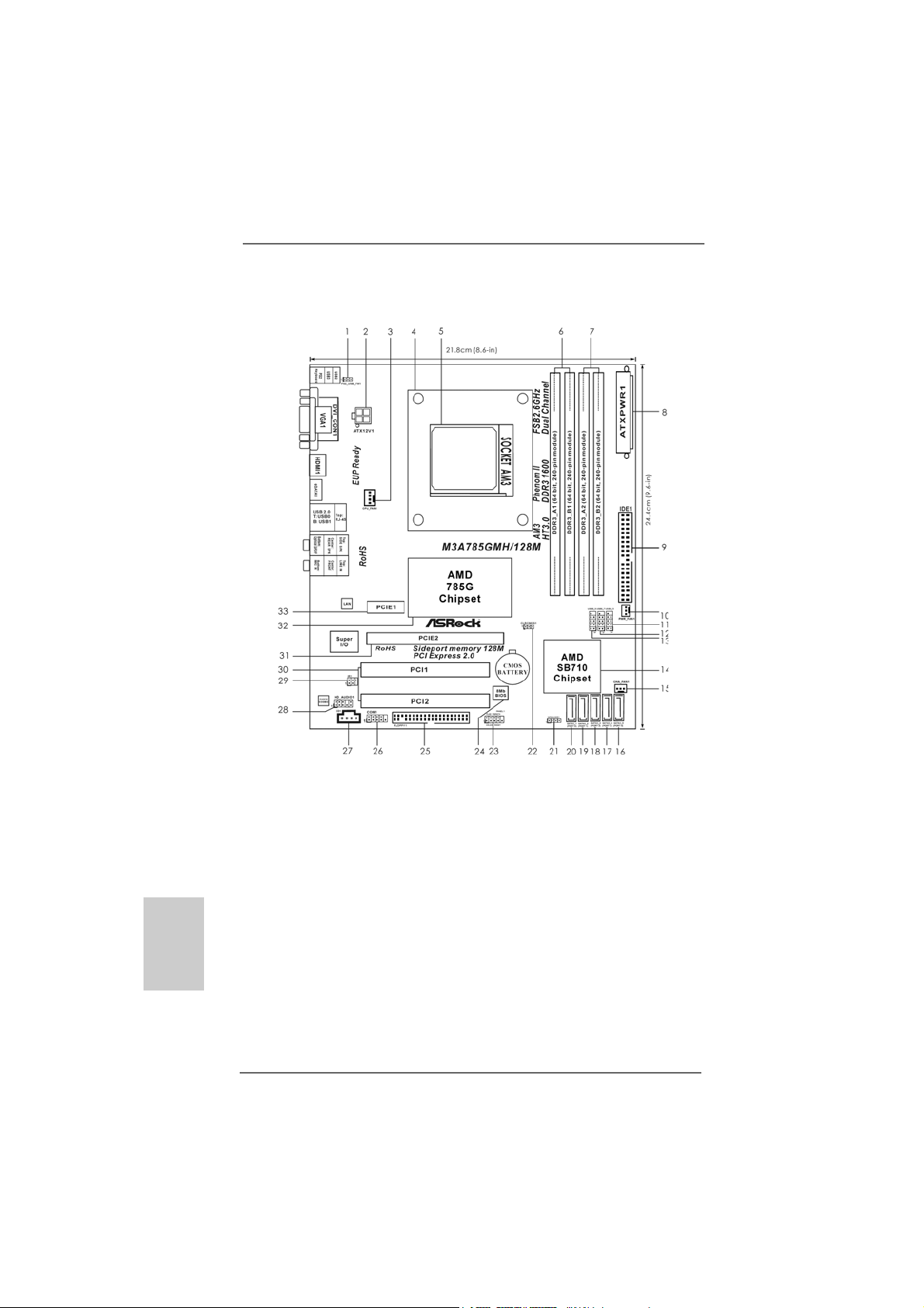
1 PS2_USB_PW1 Jumper 19 Secondary SAT AII Connector
2 A TX 12V Power Connector (A TX12V1) (SA T AII_2 (PORT 1))
3 CPU Fan Connector (CPU_FAN1) 20 Primary SA T AII Connector
4 CPU Heatsink Retention Module (SATAII_1 (PORT 0))
5 AM3 CPU Socket 21 Chassis Speaker Header
6 2 x 240-pin DDR3 DIMM Slots (SPEAKER 1, Purple)
(Dual Channel A: DDR3_A1, DDR3_B1; Blue) 22 Clear CMOS Jumper (CLRCMOS1)
7 2 x 240-pin DDR3 DIMM Slots 23 System Panel He ader (P ANEL1, Ora nge)
(Dual Channel B: DDR3_A2, DDR3_B2; White) 24 SPI Flash Memory (8Mb)
8 ATX Power Connector (ATXPWR1) 25 Floppy Connector (FLOPPY1)
9 Primary IDE Connector (IDE1, Blue) 26 Serial Port Connector (COM1)
10 Power Fan Connector (PWR_FAN1) 27 Internal Audio Connector: CD1 (Black)
11 USB 2.0 Header (USB4_5, Blue) 28 Front Panel Audio Header
12 USB 2.0 Header (USB6_7, Blue) (HD_AUDIO1, Lime)
13 USB 2.0 Header (USB8_9, Blue) 29 Infrared Module Header (IR1)
14 Southbridge Controller 3 0 PCI Slots (PCI1- 2)
15 Chassis Fan Connector (CHA_FAN1) 31 PCI Express 2.0 x16 Slot (PCIE2; Green)
16 Fifth SAT AII Connector (SATAII_5 (PORT 4)) 32 Northbridge Controller
17 Fourth SAT AII Connector (SA TAII_4 (PORT3)) 3 3 PCI Express 2.0 x1 Slot (PCIE1; Green)
18 Third SAT AII Connector (SATAII_3 (PORT 2))
ASRock M3A785GMH/128M Motherboard
Page 3
I/O PI/O P
I/O P
I/O PI/O P
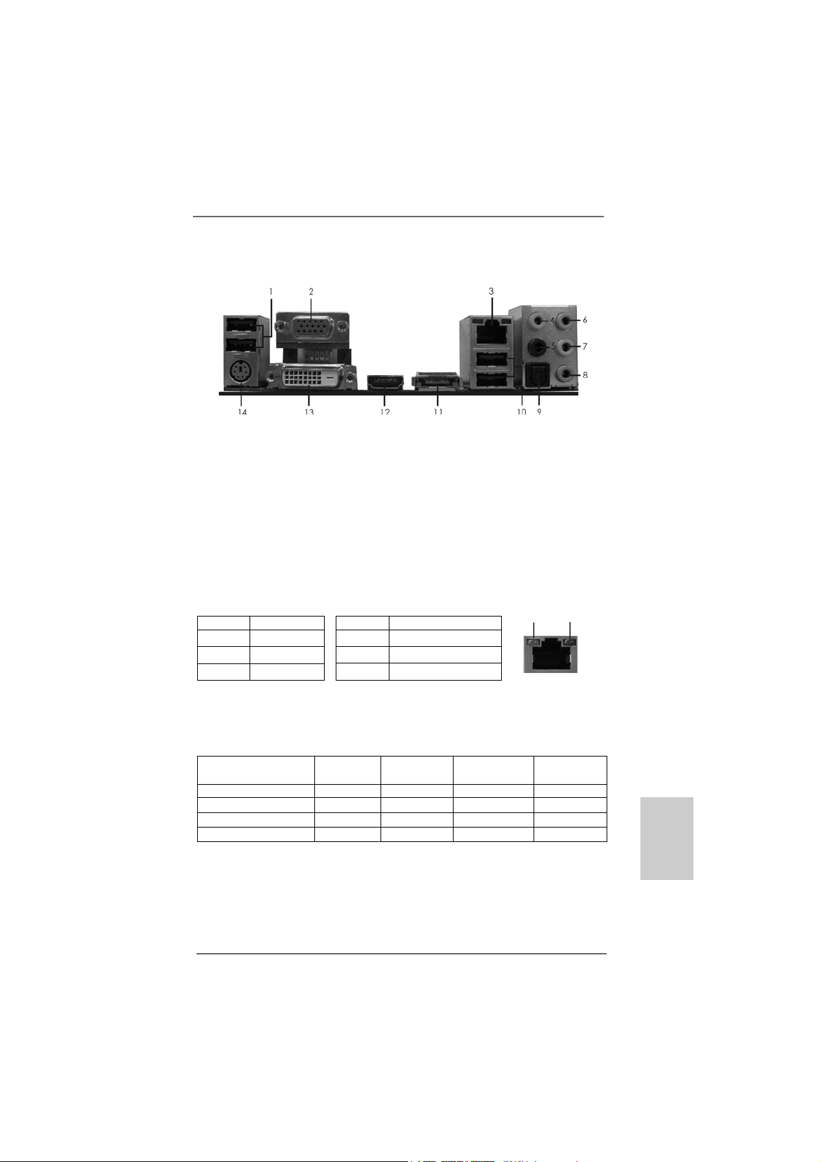
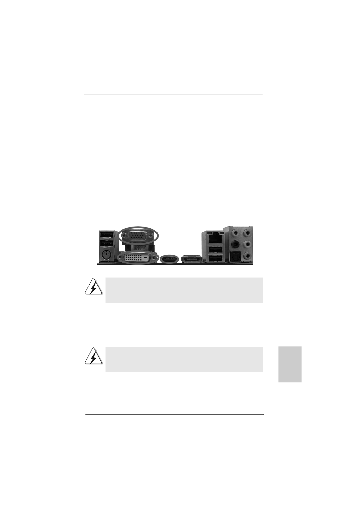
* 3 LAN RJ-45 Port 10 USB 2.0 Ports (USB01)
** 7 Front Speaker (Lime) 14 PS/2 Keyboard Port (Purple)
* There are two LED next to the LAN port. Please refer to the table below for the LAN port LED
indications.
anelanel
anel
anelanel
1 USB 2.0 Ports (USB23) 8 Microphone (Pink)
2 VGA/D-Sub Port 9 Optical SPDIF Out Port
4 Central / Bass (Orange) 11 Powered eSAT AII/USB Connector
5 Rear Speaker (Black) *** 12 HDMI Port
6 Line In (Light Blue) 13 VGA/DVI-D Port
Activity/Link LED SPEED LED
Status Description Status Description
Off No Link Off 10Mbps connection
Blinking Data Activity Orange 100Mbps connection
On Link Green 1Gbps connection
LAN Port LED Indications
ACT/LINK
LED
LAN Port
SPEED
LED
** If you use 2-channel speaker, please connect the speaker’s plug into “Front Speaker Jack”.
See the table below for connection details in accordance with the type of speaker you use.
TABLE for Audio Output Connection
Audio Output Channels Front Speaker Rear Speaker Central / Bass Line In
(No. 7) (No. 5) (No. 4) (No. 6)
2 V -- -- -4VV---6 VVV-8 VVVV
*** To support AC3 audio format with HDMI Audio under VistaTM, please install the HDMI audio
driver in XP support CD AAX785M-10.
The driver is located under the path: ..\Drivers\NB Audio\REALTEK\XP64_XP(R1.68)
And note for LPCM support up to stereo 2 channels only.
ASRock M3A785GMH/128M Motherboard
EnglishEnglish
EnglishEnglish
English
33
3
33
Page 4
1.1.
IntroductionIntroduction
1.
Introduction
1.1.
IntroductionIntroduction
Thank you for purchasing ASRock M3A785GMH/128M motherboard, a reliable
motherboard produced under ASRock’s consistently stringent quality control. It delivers excellent performance with robust design conforming to ASRock’s commitment to quality and endurance.
In this manual, cha pter 1 a nd 2 contain introduction of the motherboard a nd step-by-step
guide to the hardware installation. Chapter 3 and 4 contain the configuration guide to
BIOS setup and information of the Support CD.
Because the motherboard specifications and the BIOS software might
be updated, the content of this manual will be subject to change without
notice. In case any modifications of this manual occur, the updated
version will be available on ASRock website without further notice. You
may find the latest VGA cards and CPU support lists on ASRock website
as well. ASRock website http://www.asrock.com
If you require technical support related to this motherboard, please visit
our website for specific information about the model you are using.
www.asrock.com/support/index.asp
1.11.1
Package ContentsPackage Contents
1.1
Package Contents
1.11.1
Package ContentsPackage Contents
1 x ASRock M3A785GMH/128M Motherboard
(Micro ATX Form Factor: 9.6-in x 8.6-in, 24.4 cm x 21.8 cm)
1 x ASRock M3A785GMH/128M Quick Installation Guide
2 x ASRock M3A785GMH/128M Support CD
1 x Ultra ATA 66/100/133 IDE Ribbon Cable (80-conductor)
2 x Serial ATA (SATA) Data Cables (Optional)
1 x I/O Panel Shield
English
EnglishEnglish
EnglishEnglish
44
4
44
ASRock M3A785GMH/128M Motherboard
Page 5
1.21.2
SpecificationsSpecifications
1.2
Specifications
1.21.2
SpecificationsSpecifications
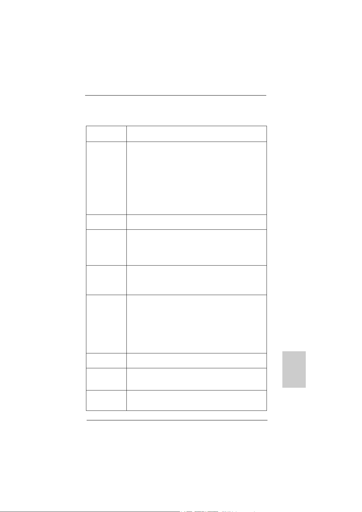
Platform - Micro ATX Form Factor: 9.6-in x 8.6-in, 24.4 cm x 21.8 cm
- Solid Capacitor for CPU power
CPU - Support for Socket AM3 processors: AMD PhenomTM II X4 /
X3 / X2 (except 920 / 940) and Athlon II X4 / X3 / X2
processors
- Supports AMD OverDriveTM with ACC feature (Advanced
Clock Calibration)
- AMD LIVE!TM Ready
- Supports AMD’s Cool ‘n’ QuietTM Technology
- FSB 2600 MHz (5.2 GT/s)
- Supports Untied Overclocking Technology (see CAUTION 1)
- Supports Hyper-Transport 3.0 (HT 3.0) Technology
Chipset - Northbridge: AMD 785G
- Southbridge: AMD SB710
Memory - Dual Channel DDR3 Memory T echnology (see CAUTION 2)
- 4 x DDR3 DIMM slots
- Support DDR3 1600/1333/1066/800 non-ECC, un-buffered
memory (see CAUTION 3)
- Max. capacity of system memory: 16GB (see CAUTION 4)
Expansion Slot - 1 x PCI Express 2.0 x16 slot (green @ x16 mode)
- 1 x PCI Express 2.0 x1 slot
- 2 x PCI slots
- Supports Hybrid CrossFireX
Graphics - Integrated AMD Radeon HD 4200 graphics
- D X10.1 class iGPU, Shader Model 4.1
- Max. shared memory 512MB (see CAUTION 5)
- Built-in 128MB DDR3 1333(OC)/1200MHz SidePort Me mory
- Three VGA Output options: D-Sub, D VI-D and HDMI
- Supports HDCP function
- Supports Full HD 1080p Blu-ray (BD) / HD-DVD playback
(see CAUTION 6)
Audio - 7.1 CH Windows® VistaTM Premium Level HD Audio
(Realtek ALC888 Audio Codec)
LAN - PCIE x1 Giga bit LAN 10/100/1000 Mb/s
- Realtek RTL81 11DL
- Supports Wake-On-LAN
Rear Panel I/O I/O Panel
- 1 x PS/2 Keyboard Port
- 1 x VGA/D-Sub Port
TM
EnglishEnglish
EnglishEnglish
English
ASRock M3A785GMH/128M Motherboard
55
5
55
Page 6
English
EnglishEnglish
EnglishEnglish
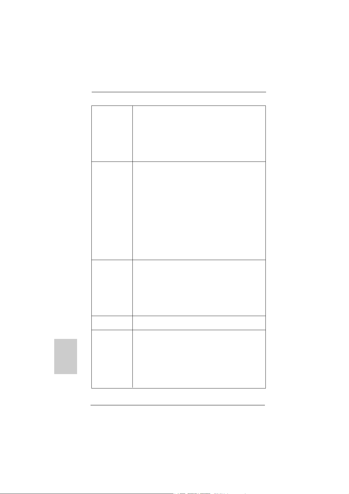
- 1 x VGA/DVI-D Port
- 1 x HDMI Port
- 1 x Optical SPDIF Out Port
- 1 x eSATAII Port
- 4 x Ready-to-Use USB 2.0 Ports
- 1 x RJ-45 LAN Port with LED (ACT/LINK LED and SPEED LED)
- HD Audio Jack: Rear Speaker/Central/Bass/Line in/Front
Speaker/Microphone (see CAUTION 7)
Connector - 5 x Serial ATAII 3.0Gb/s connectors, support RAID (RAID 0,
RAID 1, RAID 10 and JBOD), NCQ, AHCI a nd “Hot Plug”
functions (see CAUTION 8)
- 1 x ATA133 IDE connector (supports 2 x IDE devices)
- 1 x Floppy connector
- 1 x IR header
- 1 x COM port header
- CPU/Chassis/Power FAN connector
- 24 pin ATX power connector
- 4 pin 12V power connector
- CD in header
- Front panel audio connector
- 3 x USB 2.0 headers (support 6 USB 2.0 ports)
(see CAUTION 9)
BIOS Feature - 8Mb AMI BIOS
- AMI Legal BIOS
- Supports “Plug and Play”
- ACPI 1.1 Compli ance Wa ke Up Events
- Supports jumperfree
- SMBIOS 2.3.1 Support
- VCCM, NB Voltage Multi-a djustment
- Supports Smart BIOS
Support CD - Drivers, Utilities, AntiVirus Software (Trial Version), AMD
OverDriveTM Utility, AMD Live! Explorer, AMD Fusion
Unique Feature - ASRock OC Tuner (see CAUTION 10)
- Intelligent Energy Saver (see CAUTION 11)
- Instant Boot
- ASRock Instant Flash (see CAUTION 12)
- Hybrid Booster:
- CPU Frequency Stepless Control (see CAUTION 13)
- ASRock U-COP (see CAUTION 14)
- Boot Failure Guard (B.F.G.)
66
6
66
ASRock M3A785GMH/128M Motherboard
Page 7
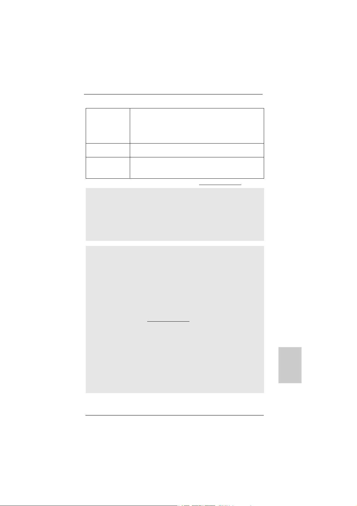
Hardware - CPU Temperature Sensing
Monitor - Chassis Temperature Sensing
- CPU/Chassis/Power Fan Tachometer
- CPU Quiet Fan
- Voltage Monitoring: +12V, +5V, +3.3V, Vcore
OS - Microsoft® Windows® XP / XP Media Center / XP 64-bit /
TM
Vista
/ VistaTM 64-bit compliant
Certifications - FCC, CE, Microsoft® WHQL Certificated
- EuP Ready (EuP ready power supply is required)
(see CAUTION 15)
* For detailed product information, please visit our website: http://www.asrock.com
WARNING
Please realize that there is a certain risk involved with overclocking, including adjusting
the setting in the BIOS, applying Untied Overclocking Technology, or using the thirdparty overclocking tools. Overclocking may affect your system stability, or even
cause damage to the components and devices of your system. It should be done at
your own risk and expense. We are not responsible for possible damage caused by
overclocking.
CAUTION!
1. This motherboard supports Untied Overclocking Te chnology. Please read “Untied Overclocking Technology” on page 28 for details.
2. This motherboard supports Dual Channel Memory Te chnology. Before you
implement Dual Channel Memory Technology, make sure to read the
installation guide of memory modules on page 14 for proper installation.
3. Whether 1600MHz memory speed is supported depends on the AM3 CPU
you adopt. If you want to adopt DDR3 1600 memory module on this
motherboard, please refer to the memory support list on our website for
the compatible memory modules.
ASRock website http://www.asrock.com
4. Due to the operating system limitation, the actual memory size may be
less than 4GB for the reservation for system usage under Windows® XP
and Windows® VistaTM. For Windows® XP 64-bit and Windows® VistaTM 64bit with 64-bit CPU, there is no such limitation.
5. The maximum shared memory size is defined by the chipset vendor and
is subject to change. Please check AMD website for the latest information.
6. 1080p Blu-ray (BD) / HD-DVD playback support on this motherboard requires
the proper hardware configuration. Please refer to page 10 and 11 for the
minimum hardware requirement and the passed 1080p Blu-ray (BD) / HD-DVD
films in our lab test.
EnglishEnglish
EnglishEnglish
English
ASRock M3A785GMH/128M Motherboard
77
7
77
Page 8

English
EnglishEnglish
EnglishEnglish
7. For microphone input, this motherboard supports both stereo and mono modes.
For audio output, this motherboard supports 2-channel, 4-channel, 6-channel,
and 8-channel mode s. Please check the table on page 3 for proper connection.
8. Before installing SAT AII hard dis k to SATAII connector, please read the “SATAII
Hard Disk Setup Guide” on page 30 of “User Manual” in the support CD to
adjust your SA TAII hard disk drive to SA TAII mode. You can also connect SA TA
hard disk to SATAII connector directly.
9. Power Management for USB 2.0 works fine under Microsoft® Windows
VistaTM 64-bit / VistaTM / XP 64-bit / XP SP1 or SP2.
10. It is a user-friendly ASRock overclocking tool which allows you to surveil
your system by hardware monitor function and overclock your hardware
devices to get the best system performance under Windows® environment.
Please visit our website for the operation procedures of ASRock OC
Tuner . ASRock website: http://www.asrock.com
11. Featuring an advanced proprietary hardware and software design,
Intelligent Energy Saver is a revolutionary technology that delivers
unparalleled power savings. The voltage regulator can reduce the
number of output phases to improve efficiency when the CPU cores are
idle. In other words, it is able to provide exceptional power saving and
improve power efficiency without sacrificing computing performance. To
use Intelligent Energy Saver function, please enable Cool ‘n’ Quiet option
in the BIOS setup in advance. Please visit our website for the operation
procedures of Intelligent Energy Saver.
ASRock website: http://www.asrock.com
12. ASRock Instant Flash is a BIOS flash utility embedded in Flash ROM.
This convenient BIOS update tool allows you to update system BIOS
without entering operating systems first like MS-DOS or Windows®. With
this utility, you can press <F6> key during the POST or press <F2> key to
BIOS setup menu to access ASRock Instant Flash. Just launch this tool
and save the new BIOS file to your USB flash drive, floppy disk or hard
drive, then you can update your BIOS only in a few clicks without preparing an additional floppy diskette or other complicated flash utility. Please
be noted that the USB flash drive or hard drive must use FAT32/16/12 file
system.
13. Although this motherboard offers stepless control, it is not recommended
to perform over-clocking. Frequencies other than the recommended CPU
bus frequencies may cause the instability of the system or damage the
CPU.
14. While CPU overheat is detected, the system will automatically shutdown.
Before you resume the system, please check if the CPU fan on the
motherboard functions properly and unplug the power cord, then plug it
back again. To improve heat dissipation, remember to spray thermal
grease between the CPU a nd the he atsink when you in stall the PC system.
®
88
8
88
ASRock M3A785GMH/128M Motherboard
Page 9

15. EuP, stands for Energy Using Product, was a provision regulated by
European Union to define the power consumption for the completed system.
According to EuP, the total AC power of the completed system shall be
under 1.00W in off mode condition. To meet EuP standard, an EuP ready
motherboard and an EuP ready power supply are required. According to
Intel’s suggestion, the EuP ready power supply must meet the standard of
5v standby power efficiency is higher than 50% under 100 mA current
consumption. For EuP ready power supply selection, we recommend you
checking with the power supply manufacturer for more details.
ASRock M3A785GMH/128M Motherboard
EnglishEnglish
EnglishEnglish
English
99
9
99
Page 10
1.31.3
Minimum Hardware Requirement for 1080p Blu-rayMinimum Hardware Requirement for 1080p Blu-ray
1.3
Minimum Hardware Requirement for 1080p Blu-ray
1.31.3
Minimum Hardware Requirement for 1080p Blu-rayMinimum Hardware Requirement for 1080p Blu-ray
(BD) / HD-DVD Playback Support(BD) / HD-DVD Playback Support
(BD) / HD-DVD Playback Support
(BD) / HD-DVD Playback Support(BD) / HD-DVD Playback Support
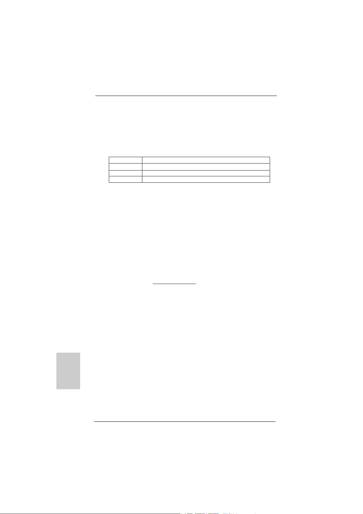
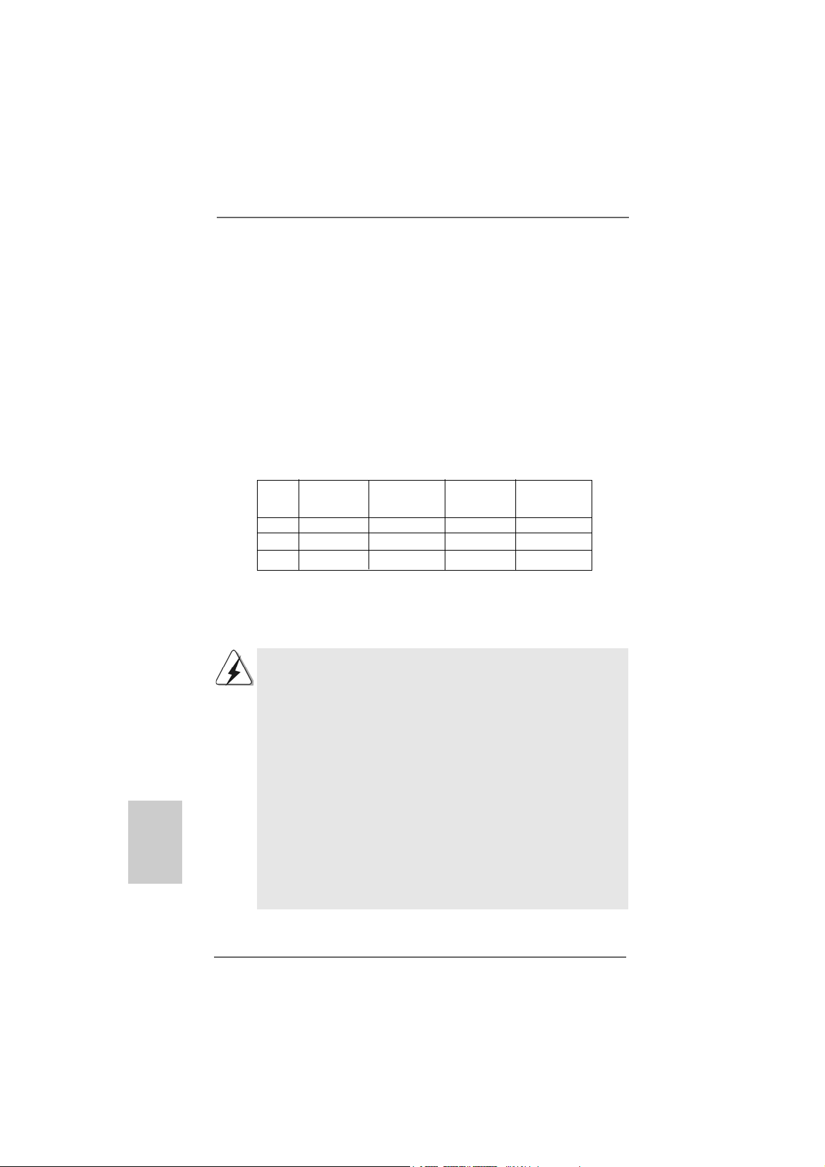
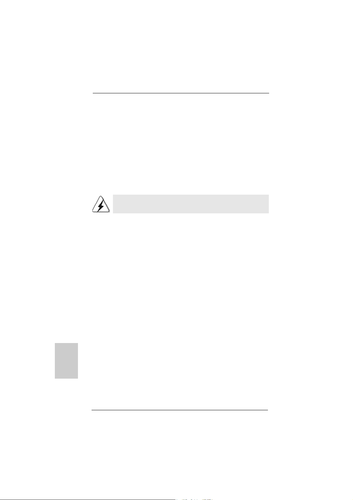
1080p Blu-ray (BD) / HD-DVD playback support on this motherboard
requires the proper hardware configuration. Please refer to below table
for the minimum hardware requirement.
CPU AM3 all series CPU
VGA Onboard VGA with DVI-D port
Memory Single Channel DDR3 1066, 1GB x 1
Suggested OS Windows® VistaTM or Windows® VistaTM 64
* If you need to use CyberLink PowerDVD Ultra version 7.3, we suggest to disable
Hardware Acceleration function for better playback performance and compatibility.
After executing CyberLink PowerDVD Ultra program, please follow below steps to
disable Hardware Acceleration function.
A. Right-click the main page of CyberLink PowerDVD Ultra program.
B. Click “Configuration”.
C. Select “Video”.
D. Click “Enable hardware acceleration (ATI Avivo)” to remove the “V” mark in
this item.
E. Click “OK” to save the change.
* Currently, 1080p Blu-ray (BD) / HD-DVD playback is only supported under Windows
VistaTM / VistaTM 64-bit OS. If you install Windows® XP / XP 64-bit OS, the function of
1080p Blu-ray (BD) / HD-DVD playback is not available, please visit our website for
AMD 790GX VGA driver update in the future.
ASRock website http://www.asrock.com
®
English
EnglishEnglish
EnglishEnglish
1010
10
1010
ASRock M3A785GMH/128M Motherboard
Page 11
1.41.4
Passed 1080p Blu-ray (BD) / HD-DVD Films in Our LabPassed 1080p Blu-ray (BD) / HD-DVD Films in Our Lab
1.4
Passed 1080p Blu-ray (BD) / HD-DVD Films in Our Lab
1.41.4
Passed 1080p Blu-ray (BD) / HD-DVD Films in Our LabPassed 1080p Blu-ray (BD) / HD-DVD Films in Our Lab
TT
estest
T
est
TT
estest
D VD Film Name Format Producer
Type
Blu-ray SWORDFISH VC-1 WB
DVD UNDERWORLD EVOLUTION MPEG-2 SONY
THE LAST STAND MPEG-4-AVC FOX
CASINO ROYALE MPEG-4-AVC SONY
THE LEAGUE OF MPEG-4-AVC FOX
EXTRAORDINARY GENTLEMEN
HD- KING KONG VC-1 UNIVERSAL
DVD NEW ORLEANS CONCERT MPEG-2 WEA
THE INTERPRETER MPEG-4-AVC UNIVERSAL
* MPEG-4-AVC mentioned above refers to the same format of H.264.
* Above passed films are tested under below configuration.
Items Configurations
CPU AM3 all series CPU
VGA Onboard VGA with DVI-D port
Memory Single Channel DDR3 1066, 1GB x 1
OS Windows® VistaTM or Windows® VistaTM 64
Playback Software CyberLink PowerDVD Ultra (Version 7.3 or above)
DVD Player Pioneer BDR-101A / LG GBW-H10N (BD)
HP HD100 (HD-DVD)
ASRock M3A785GMH/128M Motherboard
1111
11
1111
EnglishEnglish
EnglishEnglish
English
Page 12
2.2.
InstallationInstallation
2.
Installation
2.2.
InstallationInstallation
This is a Micro ATX form factor (9.6-in x 8.6-in, 24.4 cm x 21.8 cm) motherboard.
Before you install the motherboard, study the configuration of your chassis to ensure that the motherboard fits into it.
Pre-installation PrecautionsPre-installation Precautions
Pre-installation Precautions
Pre-installation PrecautionsPre-installation Precautions
Take note of the following precautions before you install motherboard
components or change any motherboard settings.
Before you install or remove any component, ensure that the
power is switched off or the power cord is detached from the
power supply. Failure to do so may cause severe damage to the
motherboard, peripherals, and/or components.
1. Unplug the power cord from the wall socket before touching any
component.
2. To avoid damaging the motherboard components due to static
electricity, NEVER place your motherboard directly on the carpet or
the like. Also remember to use a grounded wrist strap or touch a
safety grounded object before you handle components.
3. Hold components by the edges and do not touch the ICs.
4. Whenever you uninstall any component, place it on a grounded antistatic pad or in the bag that comes with the component.
5. When placing screws into the screw holes to se cure the motherboard
to the chassis, please do not over-tighten the screws! Doing so may
damage the motherboard.
English
EnglishEnglish
EnglishEnglish
1212
12
1212
ASRock M3A785GMH/128M Motherboard
Page 13
2.12.1
CPU InstallationCPU Installation
2.1
CPU Installation
2.12.1
CPU InstallationCPU Installation
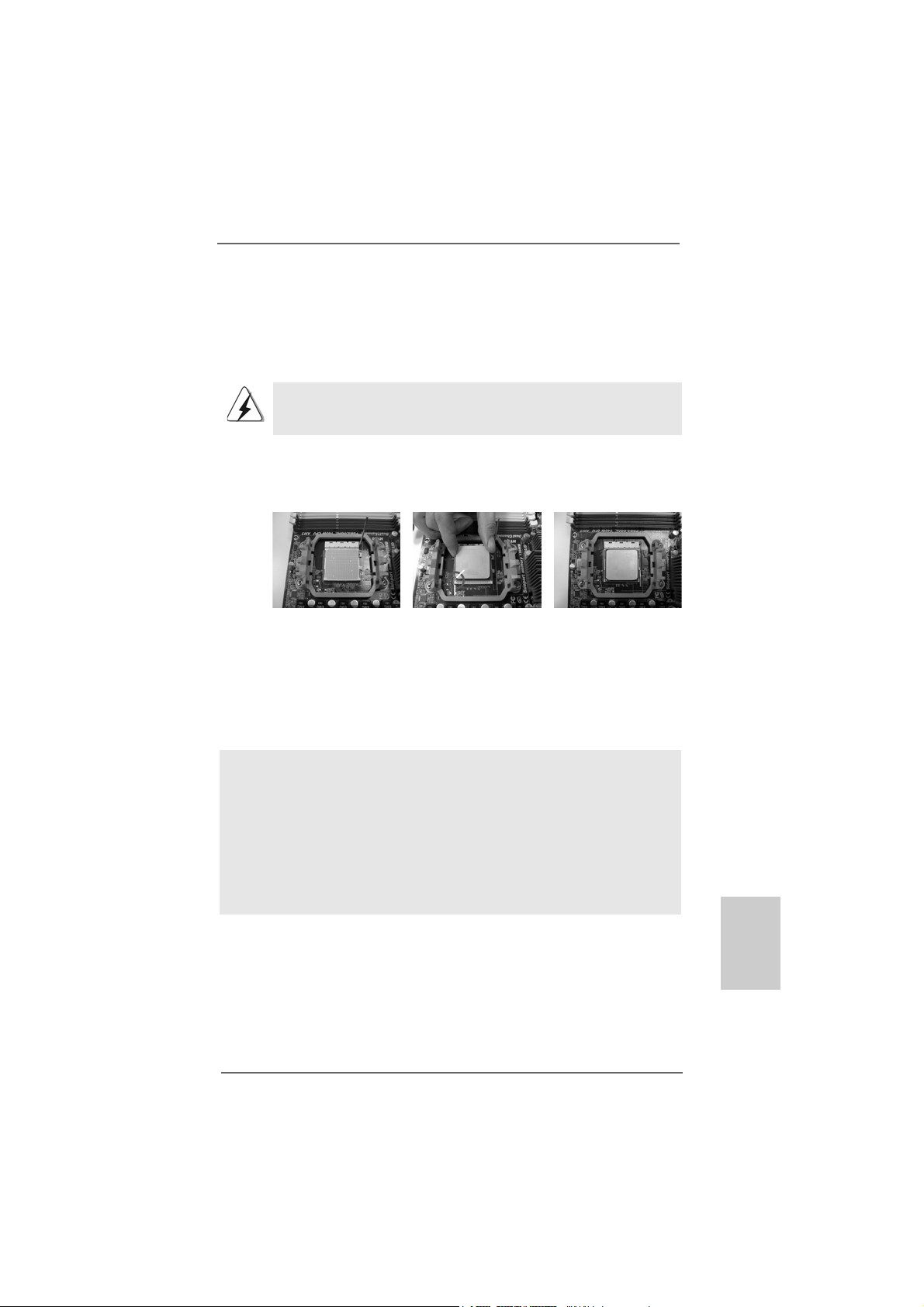
Step 1. Unlock the socket by lifting the lever up to a 90
o
angle.
Step 2. Position the CPU directly above the socket such that the CPU corner with
the golden triangle matches the socket corner with a small triangle.
Step 3. Carefully insert the CPU into the socket until it fits in place.
The CPU fits only in one correct orientation. DO NOT force the CPU
into the socket to avoid bending of the pins.
Step 4. When the CPU is in place, press it firmly on the socket while you push
down the socket lever to secure the CPU. The lever clicks on the side tab
to indicate that it is locked.
Lever 90° Up
CPU Golden Triangle
Socker Corner Small Triangle
STEP 1:
Lift Up The Socket Lever
2.22.2
Installation of CPU Fan and HeatsinkInstallation of CPU Fan and Heatsink
2.2
Installation of CPU Fan and Heatsink
2.22.2
Installation of CPU Fan and HeatsinkInstallation of CPU Fan and Heatsink
STEP 2 / STEP 3:
Match The CPU Golden Triangle
To The Socket Corner Small
Triangle
STEP 4:
Push Down And Lock
The Socket Lever
After you install the CPU into this motherboard, it is necessary to install a
larger heatsink and cooling fan to dissipate heat. You also need to spray
thermal grease between the CPU and the heatsink to improve heat
dissipation. Make sure that the CPU and the heatsink are securely fastened and in good contact with each other. Then connect the CPU fan to
the CPU FAN connector (CPU_FAN1, see Page 2, No. 3). For proper
installation, please kindly refer to the instruction manuals of the CPU fan
and the heatsink.
ASRock M3A785GMH/128M Motherboard
1313
13
1313
EnglishEnglish
EnglishEnglish
English
Page 14
2.3 Installation of Memory Modules (DIMM)2.3 Installation of Memory Modules (DIMM)
2.3 Installation of Memory Modules (DIMM)
2.3 Installation of Memory Modules (DIMM)2.3 Installation of Memory Modules (DIMM)
This motherboard provides four 240-pin DDR3 (Double Data Rate 3) DIMM slots,
and supports Dual Channel Memory Technology. For dual channel configuration,
you always need to install identical (the same brand, speed, size and chiptype) DDR3 DIMM pair in the slots of the same color. In other words, you have to
install identical DDR3 DIMM pair in Dual Channel A (DDR3_A1 and DDR3_B1;
Blue slots; see p.2 No.6) or identical DDR3 DIMM pair in Dual Channel B
(DDR3_A2 and DDR3_B2; White slots; see p.2 No.7), so that Dual Channel
Memory Technology can be activated. This motherboard also allows you to
install four DDR3 DIMMs for dual channel configuration, and please install iden-
tical DDR3 DIMMs in all four slots. You may refer to the Dual Channel Memory
Configuration Table below.
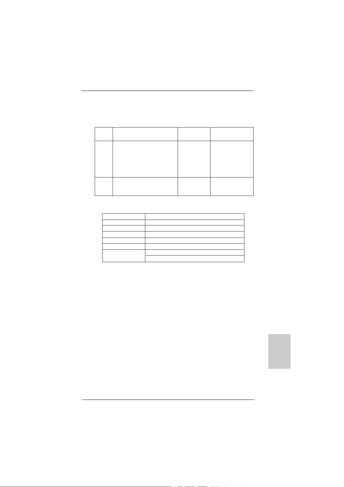
Dual Channel Memory Configurations
DDR3_A1 DDR3_B1 DDR3_A2 DDR3_B2
(Blue Slot) (Blue Slot) (White Slot) (White Slot)
(1) Populated Populated - (2) - - Populated Populated
(3)* Populated Populated Populated Populated
* For the configuration (3), please install identical DDR3 DIMMs in all four
slots.
English
EnglishEnglish
EnglishEnglish
1414
14
1414
1. If you want to install two memory modules, for optimal compatibility
and reliability, it is recommended to install them in the slots of the
same color. In other words, install them either in the set of blue slots
(DDR3_A1 and DDR3_B1), or in the set of white slots (DDR3_A2
and DDR3_B2).
2. If only one memory module or three memory modules are installed
in the DDR3 DIMM slots on this motherboard, it is unable to activate
the Dual Channel Memory T e chnology.
3. If a pair of memory modules is NOT installed in the same Dual
Channel, for example, installing a pair of memory modules in
DDR3_A1 and DDR3_A2, it is unable to activate the Dual Channel
Memory Technology .
4. It is not allowed to install a DDR or DDR2 memory module into
DDR3 slot; otherwise, this motherboard and DIMM may be damaged.
5. If you adopt DDR3 1600 memory modules on this motherboard, it is
recommended to install them on DDR3_A2 and DDR3_B2 slots.
ASRock M3A785GMH/128M Motherboard
Page 15
Installing a DIMMInstalling a DIMM
Installing a DIMM
Installing a DIMMInstalling a DIMM
Please make sure to disconnect power supply before adding or
removing DIMMs or the system components.
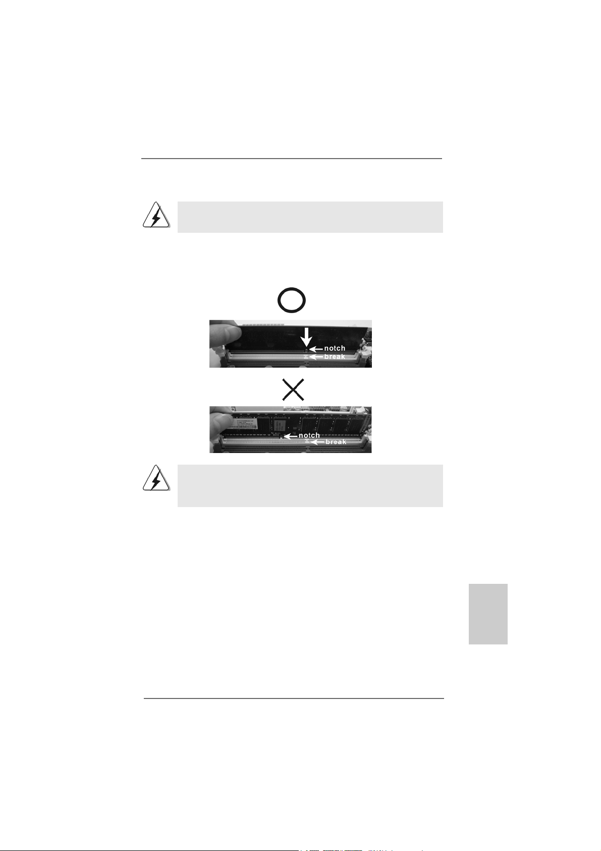
Step 1. Unlock a DIMM slot by pressing the retaining clips outward.
Step 2. Align a DIMM on the slot such that the notch on the DIMM matches the brea k
on the slot.
The DIMM only fits in one correct orientation. It will cause permanent
damage to the motherboard and the DIMM if you force the DIMM into the slot
at incorrect orientation.
Step 3. Firmly insert the DIMM into the slot until the retaining clips at both ends fully
snap back in place and the DIMM is properly seated.
ASRock M3A785GMH/128M Motherboard
1515
15
1515
EnglishEnglish
EnglishEnglish
English
Page 16

2.4 Expansion Slots (PCI and PCI Express Slots)2.4 Expansion Slots (PCI and PCI Express Slots)
2.4 Expansion Slots (PCI and PCI Express Slots)
2.4 Expansion Slots (PCI and PCI Express Slots)2.4 Expansion Slots (PCI and PCI Express Slots)
There are 2 PCI slots and 2 PCI Express slots on this motherboard.
PCI slots: PCI slots are used to install expansion cards that have the 32-bit PCI
interface.
PCIE slots:
PCIE1 (PCIE x1 slot; Green) is used for PCI Express cards with x1 lane
width cards, such as Gigabit LAN card, SATA2 card, etc.
PCIE2 (PCIE x16 slot; Green) is used for PCI Express cards with x16
lane width graphics cards.
Installing an expansion cardInstalling an expansion card
Installing an expansion card
Installing an expansion cardInstalling an expansion card
Step 1. Before installing the expansion card, please make sure that the power
supply is switched off or the power cord is unplugged. Please read the
documentation of the expansion card and make necessary hardware
settings for the card before you start the installation.
Step 2. Remove the bracket facing the slot that you intend to use. Keep the screws
for later use.
Step 3. Align the card connector with the slot and press firmly until the card is
completely seated on the slot.
Step 4. F asten the card to the chassis with screws.
English
EnglishEnglish
EnglishEnglish
1616
16
1616
ASRock M3A785GMH/128M Motherboard
Page 17
2.5 Dual Monitor and Surround Display Features2.5 Dual Monitor and Surround Display Features
2.5 Dual Monitor and Surround Display Features
2.5 Dual Monitor and Surround Display Features2.5 Dual Monitor and Surround Display Features
Dual Monitor Feature
This motherboard supports dual monitor feature. With the internal VGA output
support (DVI-D, D-Sub and HDMI), you can easily enjoy the benefits of dual monitor
feature without installing any add-on VGA card to this motherboard. This
motherboard also provides independent display controllers for DVI-D, D-Sub or
HDMI to support dual VGA output so that DVI-D, D-sub or HDMI can drive same or
different display contents.
To enable dual monitor feature, please follow the below steps:
1. Connect DVI-D monitor cable to VGA/DVI-D port on the I/O panel, connect D-Sub
monitor cable to VGA/D-Sub port on the I/O panel, or connect HDMI monitor
cable to HDMI port on the I/O panel.
VGA/D-Sub port
VGA/DVI-D port
DVI-D and HDMI monitors cannot display at the same time. You can only
choose the combination for dual monitor output support: DVI-D + D-Sub
or HDMI + D-Sub.
2. If you have installed onboard VGA driver from our support CD to your system
already, you can freely enjoy the benefits of multi monitor function after your
system boots. If you haven’t installed onboard VGA driver yet, please install
onboard VGA driver from our support CD to your system and restart your
computer. Then you can start to use multi monitor function on this motherboard.
When you playback HDCP-protected video from Blu-ray (BD) or
HD-DVD disc, the content will be displayed only in one of the three
monitors instead of all monitors.
ASRock M3A785GMH/128M Motherboard
HDMI port
1717
17
1717
EnglishEnglish
EnglishEnglish
English
Page 18
Surround Display Feature
This motherboard supports surround display upgrade. With the internal VGA
output support (DVI-D, D-Sub and HDMI) and external add-on PCI Express VGA
card, you can easily enjoy the benefits of surround display feature.
Please refer to the following steps to set up a surround display environment:
1. Install the ATITM PCI Express VGA cards on PCIE2 slot. Please refer to page 16
for proper expansion card installation procedures for details.
2. Connect DVI-D monitor cable to VGA/DVI-D port on the I/O panel, connect D-Sub
monitor cable to VGA/D-Sub port on the I/O panel, or connect HDMI monitor
cable to HDMI port on the I/O panel. Then connect other monitor cables to the
corresponding connectors of the add-on PCI Express VGA cards on PCIE2 slot.
DVI-D and HDMI monitors cannot display at the same time. You can only
choose the combination: DVI-D + D-Sub or HDMI + D-Sub.
3. Boot your system. Press <F2> to enter BIOS setup. Enter “Share Memory”
option to adjust the memory capability to [32MB], [64MB], [128MB] [256MB] or
[512MB] to enable the function of VGA/D-sub. Please make sure that the value
you select is less than the total capability of the system memory. If you do not
adjust the BIOS setup, the default value of “Share Memory”, [Auto], will disable
VGA/D-Sub function when the add-on VGA card is inserted to this
motherboard.
4. Install the onboard VGA driver and the add-on PCI Express VGA card driver to
your system. If you have installed the drivers already, there is no need to install
them again.
5. Set up a multi-monitor display.
English
EnglishEnglish
EnglishEnglish
1818
18
1818
For Windows® XP / XP 64-bit OS:
Right click the desktop, choose “Properties”, and select the “Settings” tab
so that you can adjust the parameters of the multi-monitor according to the
steps below.
A. Click the “Identify” button to display a large number on each monitor.
B. Right-click the display icon in the Display Properties dialog that you wish
to be your primary monitor, and then select “Primary”. When you use
multiple monitors with your card, one monitor will always be Primary,
and all additional monitors will be designated as Secondary.
C. Select the display icon identified by the number 2.
D. Click “Extend my Windows desktop onto this monitor”.
E. Right-click the display icon and select “Attached”, if necessary.
F. Set the “Screen Resolution” and “Color Quality” as appropriate for the
second monitor. Click “Apply” or “OK” to apply these new values.
ASRock M3A785GMH/128M Motherboard
Page 19

G. Repeat steps C through E for the diaplay icon identified by the number
one, two, three and four.
For Windows® VistaTM / VistaTM 64-bit OS:
Right click the desktop, choose “Personalize”, and select the “Display
Settings” tab so that you can adjust the parameters of the multi-monitor
according to the steps below.
A. Click the number ”2” icon.
B. Click the items “This is my main monitor” and “Extend the desktop onto
this monitor”.
C. Click “OK” to save your change.
D. Repeat steps A through C for the display icon identified by the number
three and four.
6. Use Surround Display. Click and drag the display icons to positions representing
the physical setup of your monitors that you would like to use. The placement
of display icons determines how you move items from one monitor to another.
HDCP Function
HDCP function is supported on this motherboard. To use HDCP
function with this motherboard, you need to adopt the monitor that
supports HDCP function as well. Therefore, you can enjoy the
superior display quality with high-definition HDCP encryption
contents. Please refer to below instruction for more details about
HDCP function.
What is HDCP?
HDCP stands for High-Bandwidth Digital Content Protection, a
specification developed by Intel® for protecting digital entertainment
content that uses the DVI interface. HDCP is a copy protection
scheme to eliminate the possibility of intercepting digital data
midstream between the video source, or transmitter - such as a
computer, DVD player or set-top box - and the digital display, or
receiver - such as a monitor, television or projector. In other words,
HDCP specification is designed to protect the integrity of content as it
is being transmitted.
Products compatible with the HDCP scheme such as DVD players,
satellite and cable HDTV set-top-boxes, as well as few entertainment PCs requires a secure connection to a compliant display. Due
to the increase in manufacturers employing HDCP in their equipment,
it is highly recommended that the HDTV or LCD monitor you purchase
is compatible.
ASRock M3A785GMH/128M Motherboard
1919
19
1919
EnglishEnglish
EnglishEnglish
English
Page 20
TMTM
TM
2.62.6
2.6
2.62.6
This motherboard supports ATITM Hybrid CrossFireXTM feature. ATITM Hybrid
CrossFireXTM brings multi-GPU performance capabilities by enabling an AMD 785G
integrated graphics processor and a discrete graphics processor to operate
simultaneously with combined output to a single display for blisteringly-fast frame
rates. Currently, ATITM Hybrid CrossFireXTM Technology is only supported with
Windows® Vista
ATITM Hybrid CrossFireXTM may be supported with Windows® XP OS. Please visit
our website for updated information.
TMTM
AA
TITI
Hybrid CrossF Hybrid CrossF
A
TI
Hybrid CrossF
AA
TITI
Hybrid CrossF Hybrid CrossF
TM
OS, and is not available with Windows® XP OS. In the future,
TMTM
TM
TMTM
ireXireX
Operation Guide Operation Guide
ireX
Operation Guide
ireXireX
Operation Guide Operation Guide
English
EnglishEnglish
EnglishEnglish
What does an ATITM Hybrid CrossFireXTM system include?
An ATITM Hybrid CrossFireXTM system includes an ATITM RadeonTM 2400 or ATI
RadeonTM 3450 series graphics processor and a motherboard based on an AMD
785G integrated chipset, all operating in a Windows® VistaTM environment.
Please refer to below PCI Express graphics card support list for ATITM Hybrid
CrossFireXTM. For the future update of more compatible PCI Express graphics
cards, please visit our website for further information.
Vendor Chipset Model Driver
A TI RADEON X2400PRO MSI RX2400 PRO-TD256EH Catalyst 8.7
RADEON HD3450 POWERCOLOR AX3450 Catalyst 8.7
256MD2-S
TMTM
TM
Enjoy the benefit of AEnjoy the benefit of A
Enjoy the benefit of A
Enjoy the benefit of AEnjoy the benefit of A
Step 1. Install one compatible PCI Express graphics card to PCIE2 slot (green). For
the proper installation procedures, please refer to section “Expansion Slots”.
Step 2. Connect the monitor cable to the correspondent connector on the PCI
Express graphics card on PCIE2 slot.
Step 3. Boot your system. Press <F2> to enter BIOS setup. Enter “Advanced”
screen, and enter “Chipset Settings”. Then set the option “Surround View”
to [Enabled].
Step 4. Boot into OS. Please remove the ATITM driver if you have any VGA driver
installed in your system.
Step 5. Install the onboard VGA driver from our support CD to your system for both
the onboard VGA and the discrete graphics card.
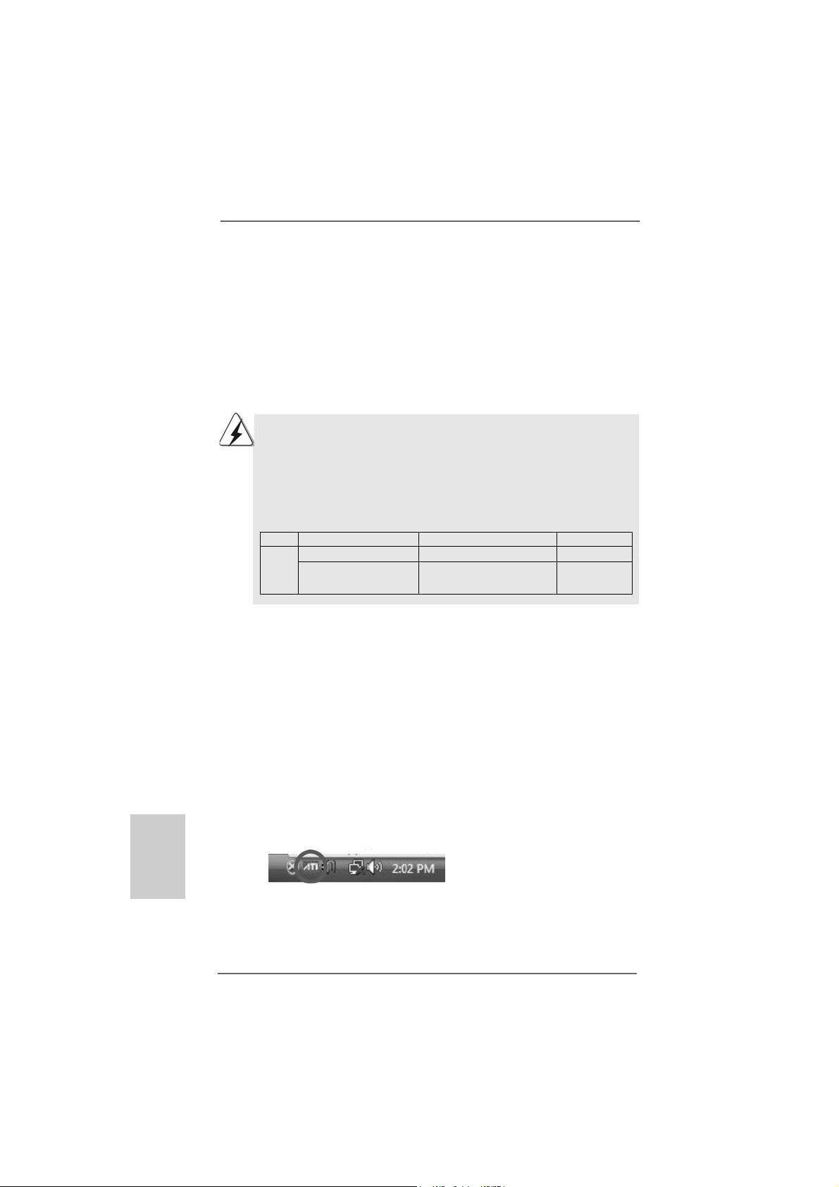
Step 6. Restart your computer. Then you will find “ATI Catalyst Control Center” on
your Windows® taskbar.
TMTM
TITI
Hybrid CrossF Hybrid CrossF
TI
Hybrid CrossF
TITI
Hybrid CrossF Hybrid CrossF
ireXireX
ireX
ireXireX
TMTM
TM
TMTM
TM
2020
20
2020
ATI Catalyst Control Center
ASRock M3A785GMH/128M Motherboard
Page 21
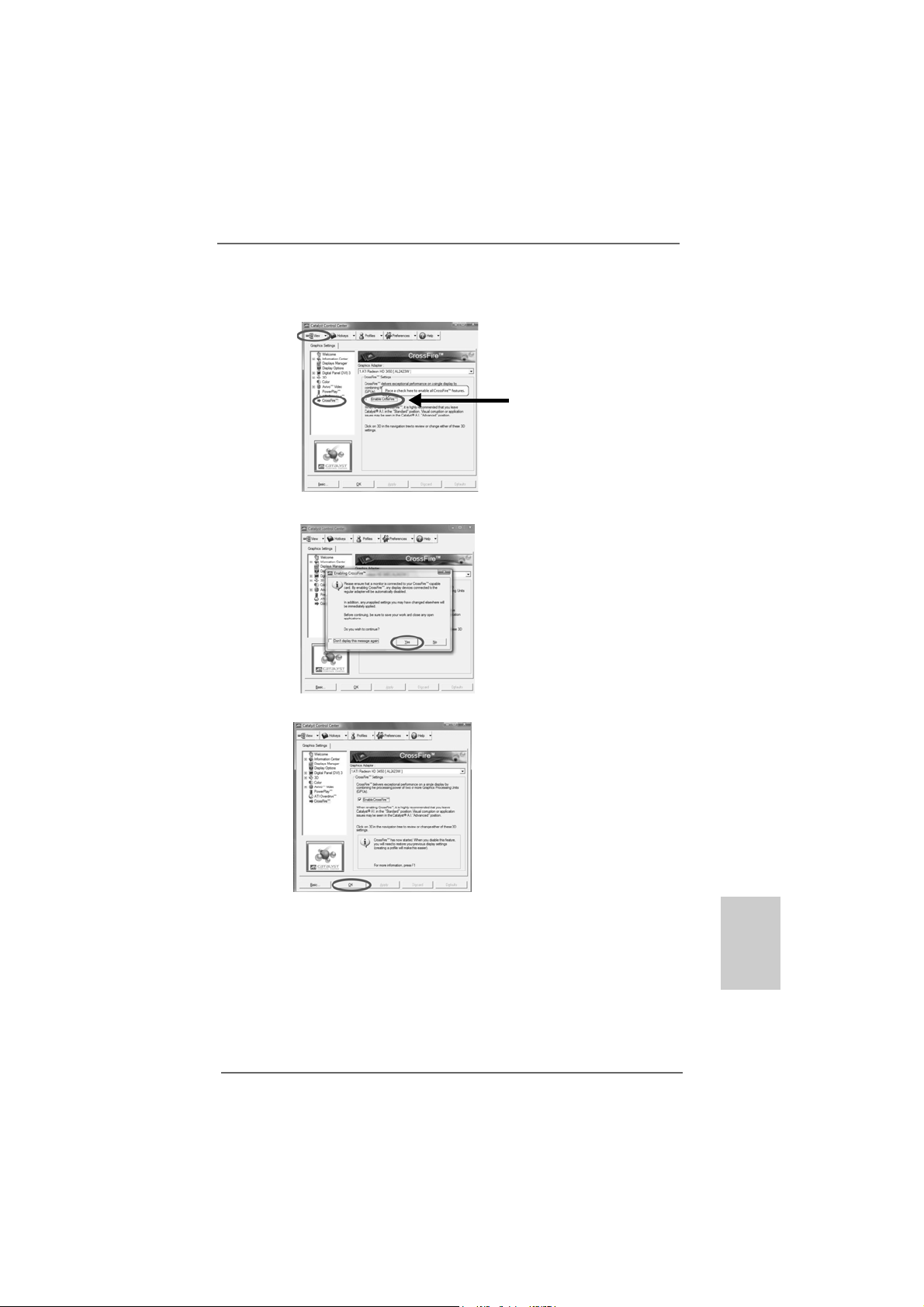
Step 7. Double-click “ATI Catalyst Control Center”. Click “V iew”, click “CrossFireTM”,
and then select the option “Enable CrossFireTM”.
View
CrossFire
TM
Step 8. Click “Yes” to continue.
Step 9. Click “OK” to save your change.
Enable CrossFire
TM
Step 10. Reboot your system. Then you can freely enjoy the benefit of Hybrid
TM
CrossFireXTM feature.
* Hybrid CrossFireXTM appearing here is a registered trademark of ATITM Technologies Inc.,
and is used only for identification or explanation and to the owners’ benefit, without intent to
infringe.
* For further information of ATITM Hybrid CrossFireXTM technology, please check AMD website
for up dates and details.
ASRock M3A785GMH/128M Motherboard
2121
21
2121
EnglishEnglish
EnglishEnglish
English
Page 22
2.72.7
Jumpers SetupJumpers Setup
2.7
Jumpers Setup
2.72.7
Jumpers SetupJumpers Setup
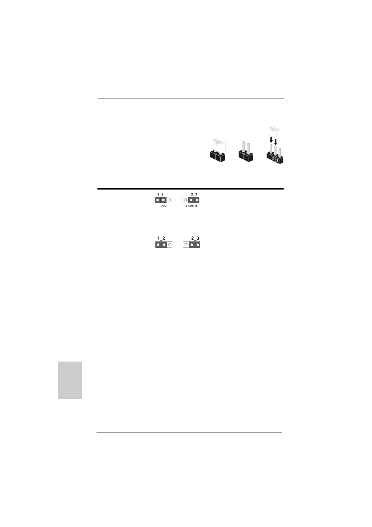
The illustration shows how jumpers are setup.
When the jumper cap is placed on pins, the
jumper is “Short”. If no jumper cap is pla ced on
pins, the jumper is “Open”. The illustration
shows a 3-pin jumper whose pin1 and
pin2 are “Short” when jumper cap is pla ced on
these 2 pins.
Jumper Setting
PS2_USB_PW1 Short pin2, pin3 to enable
(see p.2, No. 1) +5VSB (standby) for PS/2 or
USB wake up events.
Note: To select +5VSB, it requires 2 Amp and higher sta ndby current provided by
power supply.
Clear CMOS Jumper
(CLRCMOS1)
(see p.2, No. 22)
Note: CLRCMOS1 allows you to clear the data in CMOS. The data in CMOS includes
system setup information such as system password, date, time, and system
setup parameters. To clear and reset the system parameters to default setup,
please turn of f the computer and unplug the power cord from the power supply.
After waiting for 15 seconds, use a jumper ca p to short pin2 and pin3 on CLRCMOS1
for 5 seconds. However , please do not clear the CMOS right after you update the
BIOS. If you need to clear the CMOS when you just finish updating the BIOS, you
must boot up the system first, and then shut it down before you do the clearCMOS action.
Clear CMOSDefault
OpenShort
English
EnglishEnglish
EnglishEnglish
2222
22
2222
ASRock M3A785GMH/128M Motherboard
Page 23
2.8 Onboard Headers and Connectors2.8 Onboard Headers and Connectors
2.8 Onboard Headers and Connectors
2.8 Onboard Headers and Connectors2.8 Onboard Headers and Connectors
Onboard headers and connectors are NOT jumpers. Do NOT place
jumper caps over these headers and connectors. Placing jumper caps
over the headers and connectors will cause permanent damage of the
motherboard!
•
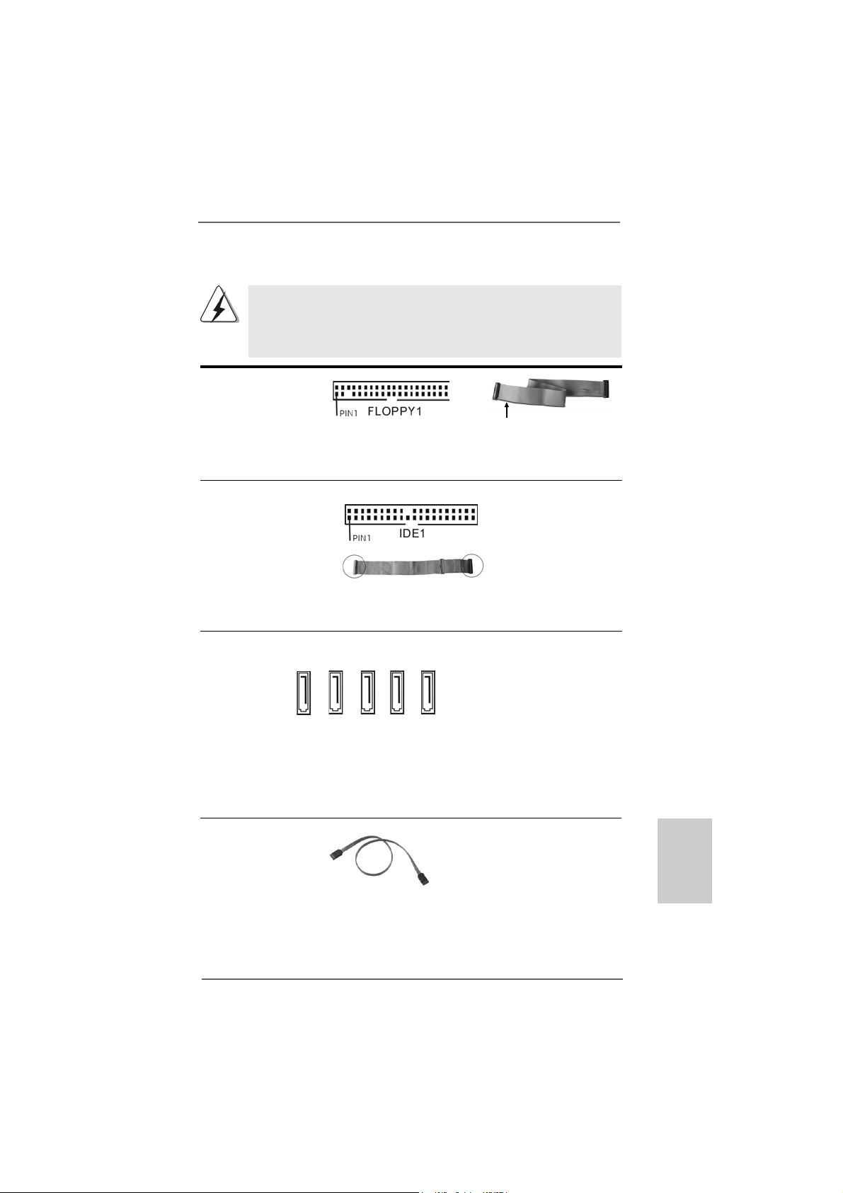
Floppy Connector
(33-pin FLOPPY1)
(see p.2 No. 25)
the red-striped side to Pin1
Note: Make sure the red-striped side of the cable is plugged into Pin1 side of the
connector.
Primary IDE connector (Blue)
(39-pin IDE1, see p.2 No. 9)
connect the blue end
to the motherboard
connect the black end
to the IDE devices
80-conductor ATA 66/100/133 cable
Note: Pl e ase re f e r t o t h e i nstruction of your IDE device vendor for the details.
Serial ATAII Connectors These five Serial ATAII (SAT AII)
(SAT AII_1 (PORT 0): connectors support SATAII
see p.2, No. 20) or SATA hard disk for internal
(SAT AII_2 (PORT 1): storage devices. The current
see p.2, No. 19) SATAII interface allows up to
(SAT AII_3 (PORT 2): 3.0Gb/s data transfer rate.
see p.2, No. 18)
(SAT AII_4 (PORT 3):
see p.2, No. 17)
(SAT AII_5 (PORT 4):
see p.2, No. 16)
SAT AII_1 (PORT 0)
SAT AII_3 (PORT 2)
SAT AII_4 (PORT 3)
SAT AII_2 (PORT 1)
SAT AII_5 (PORT 4)
Serial A TA (SA TA) Either end of the SATA data ca ble
Data Cable can be connected to the SATA /
(Optional) SATAII hard disk or the SATAII
connector on this motherboard.
EnglishEnglish
EnglishEnglish
English
ASRock M3A785GMH/128M Motherboard
2323
23
2323
Page 24
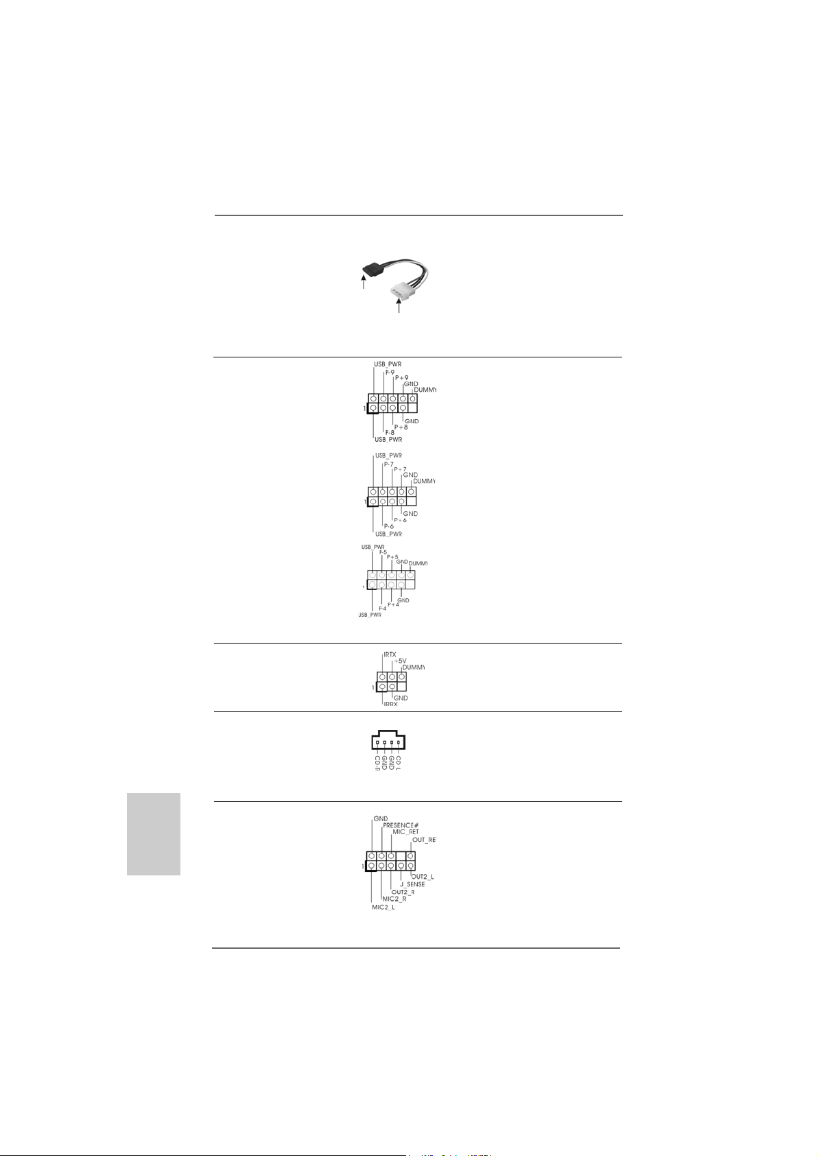
Serial ATA (SATA) Please conne ct the black end of
Power Cable SAT A power ca ble to the power
(Optional) connector on each drive. Then
connect to the SATA
HDD power connector
connect to
the power
supply
connect the white end of SATA
power cable to the power
connector of the power supply.
USB 2.0 Headers Besides four default USB 2.0
(9-pin USB8_9) ports on the I/O panel, there are
(see p.2 No. 13) three USB 2.0 headers on this
motherboard. Each USB 2.0
header can support two USB
2.0 ports.
(9-pin USB6_7)
(see p.2 No. 12)
(9-pin USB4_5)
(see p.2 No. 1 1)
Infrared Module Header This header supports an
(5-pin IR1) optional wireless transmitting
(see p.2 No. 29) and receiving infrared module.
English
EnglishEnglish
EnglishEnglish
2424
24
2424
Internal Audio Connectors This connector allows you
(4-pin CD1) to receive stereo audio input
(CD1: see p.2 No. 27) from sound sources such as
CD1
a CD-ROM, D VD-ROM, TV
tuner card, or MPEG card.
Front Panel Audio Header This is an interfa ce for the front
(9-pin HD_AUDIO1) panel audio cable that allows
(see p.2, No. 28) convenient connection and
control of audio devices.
ASRock M3A785GMH/128M Motherboard
Page 25
1. High Definition Audio supports Jack Sensing, but the panel wire on
the chassis must support HDA to function correctly. Please follow the
instruction in our manual and chassis manual to install your system.
2. If you use AC’97 audio panel, please install it to the front panel audio
header as below:
A. Connect Mic_IN (MIC) to MIC2_L.
B. Connect Audio_R (RIN) to OUT2_R and Audio_L (LIN) to OUT2_L.
C. Connect Ground (GND) to Ground (GND).
D. MIC_RET and OUT_RET are for HD audio panel only. You don’t
need to connect them for AC’97 audio panel.
E. Enter BIOS Setup Utility. Enter Advanced Settings, and then select
Chipset Configuration. Set the Front Panel Control option from
[Auto] to [Enabled].
F. Enter Windows system. Click the icon on the lower right hand
taskbar to enter Realtek HD Audio Manager.
For Windows® XP / XP 64-bit OS:
Click “Audio I/O”, select “Connector Settings” , choose
“Disable front panel jack detection”, and save the change by
clicking “OK”.
For Windows® VistaTM / VistaTM 64-bit OS:
Click the right-top “Folder” icon , choose “Disable front
panel jack detection”, and save the change by clicking “OK”.
G. To activate the front mic.
For Windows® XP / XP 64-bit OS:
Please select “Front Mic” as default record device.
If you want to hear your voice through front mic, please deselect "Mute"
icon in “Front Mic” of “Playback” portion.
For Windows® VistaTM / VistaTM 64-bit OS:
Go to the "Front Mic" Tab in the Realtek Control panel.
Click "Set Default Device" to make the Front Mic as the default record
device.
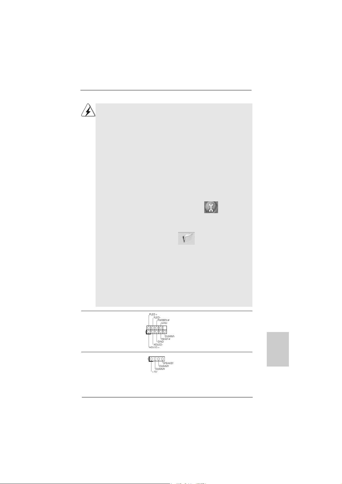
System Panel Hea der This header a ccommodate s
(9-pin PANEL1) several system front panel
(see p.2 No. 23) functions.
Chassis Spea ker He ader Please connect the chassis
(4-pin SPEAKER 1) speaker to this hea der.
(see p.2 No. 21)
ASRock M3A785GMH/128M Motherboard
2525
25
2525
EnglishEnglish
EnglishEnglish
English
Page 26
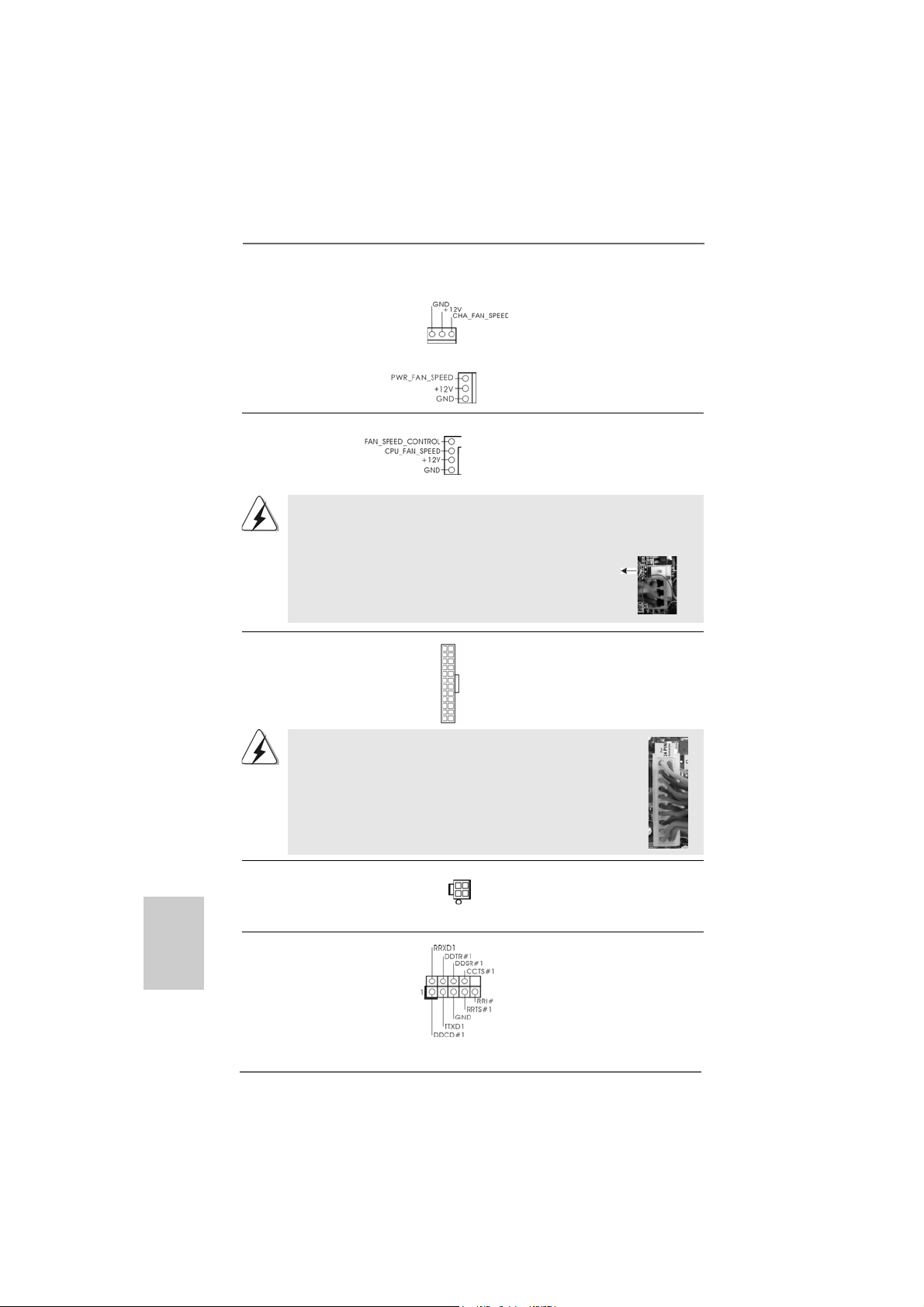
Chassis and Power Fan Connectors Please connect the fan cables
(3-pin CHA_FAN1) to the fan connectors and
(see p.2 No. 15) match the black wire to the
ground pin.
(3-pin PWR_FAN1)
(see p.2 No. 10)
English
EnglishEnglish
EnglishEnglish
CPU Fan Connector Please connect the CPU fan
(4-pin CPU_FAN1) cable to this connector and
(see p.2 No. 3) match the black wire to the
4
3
2
1
ground pin.
Though this motherboard provides 4-Pin CPU fan (Quiet Fan) support, the 3-Pin
CPU fan still can work successfully even without the fan speed control function.
If you plan to connect the 3-Pin CPU fan to the CPU fan connector on this
motherboard, please connect it to Pin 1-3.
Pin 1-3 Connected
3-Pin Fan Installation
ATX Power Connector Please connect an ATX power
(24-pin ATXPW R1) supply to this connector.
(see p.2 No. 8)
Though this motherboard provides 24-pin ATX power connector,
it can still work if you adopt a traditional 20-pin ATX power supply.
12 124
13
12
To use the 20-pin ATX power supply, please plug your power
supply along with Pin 1 and Pin 13.
20-Pin A TX Power Supply Installation
1
ATX 12V Power Connector Please connect an ATX 12V
(4-pin A TX12V1) power supply to this connector.
(see p.2 No. 2)
24
13
Serial port Header This COM1 header supports a
(9-pin COM1) serial port module.
(see p.2 No.26)
2626
26
2626
ASRock M3A785GMH/128M Motherboard
Page 27

2.92.9
Driver Installation GuideDriver Installation Guide
2.9
Driver Installation Guide
2.92.9
Driver Installation GuideDriver Installation Guide
To install the drivers to your system, please insert the support CD to your optical
drive first. Then, the drivers compatible to your system can be auto-detected and
listed on the support CD driver page. Please follow the order from up to bottom
side to install those required drivers. Therefore, the drivers you install can work
properly.
®®
®
2.102.10
Installing WindowsInstalling Windows
2.10
Installing Windows
2.102.10
Installing WindowsInstalling Windows
TMTM
TM
TMTM
VistaVista
Vista
VistaVista
If you want to install Windows® XP / XP 64-bit / VistaTM / VistaTM 64-bit on your SATA
/ SATAII HDDs with RAID functions, please refer to the document at the following path
in the Support CD for detailed procedures:
..\ RAID Installation Guide
2.112.11
Installing WindowsInstalling Windows
2.11
Installing Windows
2.112.11
Installing WindowsInstalling Windows
VistaVista
Vista
VistaVista
If you want to install Windows® XP, Windows® XP 64-bit, Windows® VistaTM or
Windows® VistaTM 64-bit OS on your SATA / SATAII HDDs without RAID functions,
please follow below procedures according to the OS you install.
2.11.1 Installing Windows2.11.1 Installing Windows
2.11.1 Installing Windows
2.11.1 Installing Windows2.11.1 Installing Windows
Functions Functions
Functions
Functions Functions
12
1
24
13
If you want to install Windows® XP or Windows® XP 64-bit on your SATA / SATAII
HDDs without RAID functions, please follow below steps.
Using SATA / SATAII HDDs without NCQ and Hot Plug functions
STEP 1: Set up BIOS.
A. Enter BIOS SETUP UTILITY Advanced screen IDE Configuration.
B. Set the “SATA Operation Mode” option to [IDE].
STEP 2: Install Windows® XP / Windows® XP 64-bit OS on your system.
64-bit W 64-bit W
64-bit W
64-bit W 64-bit W
TMTM
TM
TMTM
64-bit Without RAID Functions 64-bit Without RAID Functions
64-bit Without RAID Functions
64-bit Without RAID Functions 64-bit Without RAID Functions
®®
XP / XP 64-bit / Vista XP / XP 64-bit / Vista
XP / XP 64-bit / Vista
XP / XP 64-bit / Vista XP / XP 64-bit / Vista
ith RAID Fith RAID F
ith RAID F
ith RAID Fith RAID F
®®
®
®®
XP / XP 64-bit / Vista XP / XP 64-bit / Vista
XP / XP 64-bit / Vista
XP / XP 64-bit / Vista XP / XP 64-bit / Vista
unctionsunctions
unctions
unctionsunctions
®®
®
®®
XP / XP 64-bit Without RAID XP / XP 64-bit Without RAID
XP / XP 64-bit Without RAID
XP / XP 64-bit Without RAID XP / XP 64-bit Without RAID
TM TM
TM
TM TM
TMTM
TM
TMTM
/ /
/
/ /
//
/
//
ASRock M3A785GMH/128M Motherboard
2727
27
2727
EnglishEnglish
EnglishEnglish
English
Page 28
®®
®
TM
OS)
®®
TM
64-bit OS)
2.11.2 Installing Windows2.11.2 Installing Windows
2.11.2 Installing Windows
2.11.2 Installing Windows2.11.2 Installing Windows
RAID Functions RAID Functions
RAID Functions
RAID Functions RAID Functions
If you want to install Windows® VistaTM or Windows® VistaTM 64-bit on your SATA /
SATAII HDDs without RAID functions, please follow below steps.
Using SATA / SATAII HDDs without NCQ and Hot Plug functions
STEP 1: Set up BIOS.
A. Enter BIOS SETUP UTILITY Advanced screen IDE Configuration.
B. Set the “SATA Operation Mode” option to [IDE].
STEP 2: Install Windows® VistaTM / VistaTM 64-bit OS on your system.
Using SATA / SATAII HDDs with NCQ and Hot Plug functions
STEP 1: Set Up BIOS.
A. Enter BIOS SETUP UTILITY Advanced screen IDE Configuration.
B. Set the “SATA Operation Mode” option to [AHCI].
STEP 2: Install Windows® VistaTM / VistaTM 64-bit OS on your system.
Insert the Windows® VistaTM / Windows® VistaTM 64-bit optical disk into the optical
drive to boot your system, and follow the instruction to install Windows® VistaTM /
Windows® VistaTM 64-bit OS on your system. When you see “Where do you want to
install Windows?” page, please insert the ASRock Support CD into your optical drive,
and click the “Load Driver” button on the left on the bottom to load the AMD AHCI
drivers. AMD AHCI drivers are in the following path in our Support CD:
(There are two ASRock Support CD in the motherboard gift box pack, please
choose the one for Windows® VistaTM / VistaTM 64-bit.)
.. \ I386 (For Windows® Vista
.. \ AMD64 (For Windows® Vista
After that, please insert Windows® VistaTM / Windows® VistaTM 64-bit optical disk into
the optical drive again to continue the installation.
Vista Vista
Vista
Vista Vista
TMTM
TM
TMTM
/ Vista / Vista
/ Vista
/ Vista / Vista
TMTM
TM
TMTM
64-bit Without 64-bit Without
64-bit Without
64-bit Without 64-bit Without
English
EnglishEnglish
EnglishEnglish
2828
28
2828
2.122.12
Untied Overclocking TUntied Overclocking T
2.12
Untied Overclocking T
2.122.12
Untied Overclocking TUntied Overclocking T
This motherboard supports Untied Overclocking Technology, which means during
overclocking, FSB enjoys better margin due to fixed PCI / PCIE buses. Before you
enable Untied Overclocking function, please enter “Overclock Mode” option of BIOS
setup to set the selection from [Auto] to [CPU, PCIE, Async.]. Therefore, CPU FSB is
untied during overclocking, but PCI / PCIE buses are in the fixed mode so that FSB can
operate under a more stable overclocking environment.
Please refer to the warning on page 7 for the possible overclocking risk
before you apply Untied Overclocking Technology.
ASRock M3A785GMH/128M Motherboard
echnologyechnology
echnology
echnologyechnology
Page 29

3. BIOS Information3. BIOS Information
3. BIOS Information
3. BIOS Information3. BIOS Information
The Flash Memory on the motherboard stores BIOS Setup Utility. When you start up
the computer, please press <F2> during the Power-On-Self-Test (POST) to enter
BIOS Setup utility; otherwise, POST continues with its test routines. If you wish to
enter BIOS Setup after POST, please restart the system by pressing <Ctl> + <Alt> +
<Delete>, or pressing the reset button on the system chassis. The BIOS Setup
program is designed to be user-friendly. It is a menu-driven program, which allows
you to scroll through its various sub-menus and to select among the predetermined
choices. For the detailed information about BIOS Setup, please refer to the User
Manual (PDF file) contained in the Support CD.
4. Sof4. Sof
4. Sof
4. Sof4. Sof
This motherboard supports various Microsoft® Windows® operating systems: XP / XP
Media Center / XP 64-bit / VistaTM / VistaTM 64-bit. The Support CD that came with the
motherboard contains necessary drivers and useful utilities that will enha nce motherboard
features. To begin using the Support CD, insert the CD into your CD-ROM drive. It will
display the Main Menu automatically if “AUTORUN” is enabled in your computer. If the
Main Menu does not a ppear automatically , locate and double-click on the file “ASSETUP.
EXE” from the “BIN” folder in the Support CD to display the menus.
tware Supportware Suppor
tware Suppor
tware Supportware Suppor
t CD informationt CD information
t CD information
t CD informationt CD information
EnglishEnglish
EnglishEnglish
English
ASRock M3A785GMH/128M Motherboard
2929
29
2929
Page 30
1. Einführung1. Einführung
1. Einführung
1. Einführung1. Einführung
Wir danken Ihnen für den Kauf des ASRock M3A785GMH/128M Motherboard, ein
zuverlässiges Produkt, welches unter den ständigen, strengen Qualitätskontrollen von
ASRock gefertigt wurde. Es bietet Ihnen exzellente Leistung und robustes De sign, gemäß
der Verpflichtung von ASRock zu Qualität und Halbarkeit.
Diese Schnellinstallationsanleitung führt in das Motherboard und die schrittweise
Installation ein. Details über das Motherboard finden Sie in der
Bedienungsanleitung auf der Support-CD.
Da sich Motherboard-Spezifikationen und BIOS-Software verändern
können, kann der Inhalt dieses Handbuches ebenfalls jederzeit geändert
werden. Für den Fall, dass sich Änderungen an diesem Handbuch
ergeben, wird eine neue Version auf der ASRock-Website, ohne weitere
Ankündigung, verfügbar sein. Die neuesten Grafikkarten und unterstützten
CPUs sind auch auf der ASRock-Website aufgelistet.
ASRock-Website: http://www.asrock.com
Wenn Sie technische Unterstützung zu Ihrem Motherboard oder spezifische
Informationen zu Ihrem Modell benötigen, besuchen Sie bitte unsere
Webseite:
www.asrock.com/support/index.asp
1.1 Kartoninhalt
ASRock M3A785GMH/128M Motherboard
(Micro ATX-Formfaktor: 24.4 cm x 21.8 cm; 9.6 Zoll x 8.6 Zoll)
ASRock M3A785GMH/128M Schnellinstallationsanleitung
ASRock M3A785GMH/128M Support-CD
Ein 80-adriges Ultra-A T A 66/100/133 IDE-Flachba ndka bel
Zwei Seriell-A T A- (SA T A) Datenk abel (Option)
Ein I/O Shield
Deutsch
DeutschDeutsch
DeutschDeutsch
3030
30
3030
ASRock M3A785GMH/128M Motherboard
Page 31

1.21.2
SpezifikationenSpezifikationen
1.2
Spezifikationen
1.21.2
SpezifikationenSpezifikationen
Plattform - Micro ATX-Formfaktor: 24.4 cm x 21.8 cm; 9.6 Zoll x 8.6 Zoll
- Festkondensator für CPU-Leistung
CPU - Unterstützung von Socket AM3-Proze ssoren: AMD Phenom
II X4 / X3 / X2 (außer 920 / 940) und Athlon X4 / X3 / X2 Prozessor
- Unterstützt AMD OverDriveTM mit ACC-Funktion (Advanced
Clock Calibration, Erweiterte Taktkalibrierung)
- AMD LIVE!TM-bereit
- Unterstützt Cool ‘n’ QuietTM-T echnologie von AMD
- FSB 2600 MHz (5.2 GT/s)
- Unterstützt U ntied-Übertaktungstechnologie
(siehe VORSICHT 1)
- Unterstützt Hyper-Transport- 3.0 Technologie (HT 3.0)
Chipsatz - Northbridge: AMD 785G
- Southbridge: AMD 710
Speicher - Unterstützung von Dual-Kan al-Speichertechnologie
(siehe VORSICHT 2)
- 4 x Steckplätze für DDR3
- Unterstützt DDR3 1600/1333/1066/800 non-ECC,
ungepufferter Speicher (siehe VORSICHT 3)
- Max. Kapazität des Systemspeichers: 16GB
(siehe VORSICHT 4)
Erweiterungs- - 1 x PCI Express 2.0 x16-Steckplatz (grün für x16-Modus)
steckplätze - 1 x PCI Express 2.0 x1-Steckplatz
- 2 x PCI -Steckplätze
- Unterstützt ATITM Hybrid CrossFireX
Onboard-VGA - Integrierte AMD Radeon HD 4200-Grafik
- D X10.1 Klasse iGPU, Shader Model 4.1
- Maximal gemeinsam genutzter Speicher 512 MB
(siehe VORSICHT 5)
- Eingebauter 128MB DDR3 1333(OC)/1200MHz Side-Port-
Speicher
- Drei VGA-Ausgangsoptionen: D-Sub, DVI-D sowie HDMI
- unterstützt HDCP Funktion
- Unterstutzt 1080p Blu-ray (BD) / HD-D VD-Wiedergabe
(siehe VORSICHT 6)
Audio - 7.1 CH Windows® VistaTM Premium Level HD Audio
(ALC888 Audio Codec)
TM
TM
DeutschDeutsch
DeutschDeutsch
Deutsch
ASRock M3A785GMH/128M Motherboard
3131
31
3131
Page 32

Deutsch
DeutschDeutsch
DeutschDeutsch
LAN - PCIE x1 Gigabit LAN 10/100/1000 Mb/s
- Realtek RTL81 1 1DL
- Unterstützt W a ke-On-LAN
E/A-Anschlüsse I/O Panel
an der - 1 x PS/2-Tastaturanschluss
Rückseite - 1 x VGA/D-Sub port
- 1 x VGA/DVI-D port
- 1 x HDMI port
- 1 x optischer SPDIF-Ausgang
- 1 x eSATAII port
- 4 x Standard-USB 2.0-Anschlüsse
- 1 x RJ-45 LAN Port mit LED (ACT/LINK LED und SPEED LED)
- HD Audiobuchse: Lautsprecher hinten / Mitte/Bass /
Audioeingang/ Lautsprecher vorne / Mikrofon
(siehe VORSICHT 7)
Anschlüsse - 5 x SATAII-Anschlüsse, unterstützt bis 3.0 Gb/s
Datenübertragungsrate, unterstützt RAID (RAID 0, RAID 1,
RAID 10 und JBOD), NCQ, AHCI und “Hot Plug” Funktionen
(siehe VORSICHT 8)
- 1 x ATA133 IDE-Anschlüsse (Unterstützt bis 2 IDE-Geräte)
- 1 x FDD-Anschlüsse
- 1 x Infrarot-Modul-Header
- 1 x COM-Anschluss-Header
- CPU/Gehäuse/Stromlüfter-Anschluss
- 24-pin ATX-Netz-Header
- 4-pin anschluss für 12V -A TX-Netzteil
- Interne Audio-Anschlüsse
- Anschluss für Audio auf der Gehäusevorderseite
- 3 x USB 2.0-Anschlüsse (Unterstützung 6 zusätzlicher
USB 2.0-Anschlüsse) (siehe VORSICHT 9)
BIOS - 8Mb AMI BIOS
- AMI legal BIOS mit Unterstützung für “Plug and Play”
- ACPI 1.1-Weckfunktionen
- JumperFree-Modus
- SMBIOS 2.3.1
- VCCM, NB Stromspannung Multianpassung
- Unterstützt Smart BIOS
Support-CD - Treiber , Dienstprogra mme, Antivirussoftware (Probeversion),
AMD OverDriveTM-Dienstprogra mm, AMD Live! Explorer , AMD
Fusion
3232
32
3232
ASRock M3A785GMH/128M Motherboard
Page 33

Einzigartige - ASRock OC Tuner (siehe VORSICHT 10)
Eigenschaft - Intelligent Energy Saver (Intelligente Energiesparfunktion)
(siehe VORSICHT 11)
- Sofortstart
- ASRock Instant Flash (siehe VORSICHT 12)
- Hybrid Booster:
- Schrittloser CPU-Frequenz-Kontrolle
(siehe VORSICHT 13)
- ASRock U-COP (siehe VORSICHT 14)
- Boot Failure Guard (B.F.G. – Systemstartfehlerschutz)
Hardware Monitor - CPU-Temperatursensor
- Motherboardtemperaturerkennung
- Drehza hlmessung für CPU/Gehäuse/Stromlüfter
- CPU-Lüftergeräuschdämpfung
- Spannungsüberwachung: +12V, +5V, +3.3V, Vcore
Betriebssysteme - Unterstützt Microsoft® Windows® XP / XP Media Center /
XP 64-Bit / VistaTM / Vista
TM
64-Bit
Zertifizierungen - FCC, CE, WHQL
- Gemäß Ökodesign-Richtlinie (EuP) (Stromversorgung
gemäß Ökodesign-Richtlinie (EuP) erforderlich)
(siehe VORSICHT 15)
* Für die ausführliche Produktinformation, besuchen Sie bitte unsere Website:
http://www.asrock.com
WARNUNG
Beachten Sie bitte, dass Overclocking, einschließlich der Einstellung im BIOS, Anwenden
der Untied Overclocking-Technologie oder Verwenden von Overclocking-Werkzeugen von
Dritten, mit einem gewissen Risiko behaftet ist. Overclocking kann sich nachteilig auf die
Stabilität Ihres Systems auswirken oder sogar Komponenten und Geräte Ihres Systems
beschädigen. Es geschieht dann auf eigene Gefahr und auf Ihre Kosten. Wir übernehmen
keine Verantwortung für mögliche Schäden, die aufgrund von Overclocking verursacht
wurden.
VORSICHT!
1. Dieses Motherboard unterstützt die Untied-Übertaktungstechnologie.
Unter “Entkoppelte Übertaktungstechnologie” auf Seite 48 finden Sie
detaillierte Informationen.
2. Dieses Motherboard unterstützt Dual-Kanal-Speichertechnologie. Vor
Implementierung der Dual-Kanal-Speichertechnologie müssen Sie die
Installationsanleitung für die Speichermodule auf Seite 38 zwecks
richtigerInstallation gelesen haben.
ASRock M3A785GMH/128M Motherboard
3333
33
3333
DeutschDeutsch
DeutschDeutsch
Deutsch
Page 34

Deutsch
DeutschDeutsch
DeutschDeutsch
3434
34
3434
3. Ob die Speichergeschwindigkeit 1600 MHz unterstützt wird, hängt von der
von Ihnen eingesetzten AM3-CPU ab. Schauen Sie bitte auf unseren
Internetseiten in der Liste mit unterstützten Speichermodulen nach, wenn
Sie DDR3 1600-Speichermodule einsetzen möchten.
ASRock-Internetseite: http://www.asrock.com
4. Durch Betriebssystem-Einschränkungen kann die tatsächliche
Speichergröße weniger als 4 GB betragen, da unter Windows® XP und
Windows® Vista™ etwas Speicher zur Nutzung durch das System
reserviert wird. Unter Windows® XP 64-bit und Windows® Vista™ 64-bit
mit 64-Bit-CPU besteht diese Einschränkung nicht.
5. Die Maximalspeichergröße ist von den Chipshändler definiert und
umgetauscht. Bitte überprüfen Sie AMD website für die neuliche
Information.
6. 1080p Blu-ray (BD)/HD-DVD Playback Unterstützung auf dieser
Hauptplatine fordert die passende Hardwarekonfiguration. Bitte
verweisen Sie auf Seite 10 und 11 für minimal Hardware Anforderung
und die überschritten 1080p Blu-ray (BD)/HD-DVD Filme in unserem
Laborversuch.
7. Der Mikrofoneingang dieses Motherboards unterstützt Stereo- und
Mono-Modi. Der Audioausgang dieses Motherboards unterstützt 2Kanal-, 4-Kanal-, 6-Kanal- und 8-Kanal-Modi. Stellen Sie die richtige
Verbindung anhand der Tabelle auf Seite 3 her.
8. Vor Installation der SATAII-Festplatte an den SATAII-Anschluss lesen
Sie bitte “Setup-Anleitung für SATAII-Festplatte” auf Seite 30 der
“Bedienungsanleitung” auf der Support-CD, um Ihre SATAII-Festplatte
dem SATAII-Modus anzugleichen. Sie können die SATA-Festplatte
auch direkt mit dem SATAII-Anschluss verbinden.
9. Das Power Management für USB 2.0 arbeitet unter Microsoft
Windows® VistaTM 64-Bit / VistaTM / XP 64-Bit / XP SP1 oder SP2
einwandfrei.
10. Es ist ein benutzerfreundlicher ASRock Übertaktenswerkzeug, das
erlaubt, dass Sie Ihr System durch den Hardware-Monitor Funktion zu
überblicken und Ihre Hardware-Geräte übertakten, um die beste
Systemleistung unter der Windows® Umgebung zu erreichen.
Besuchen Sie bitte unsere Website für die Operationsverfahren von
ASRock OC Tuner. ASRock-Website: http://www.asrock.com
11. Mit einer eigenen, modernen Hardware und speziellem
Softwaredesign, bietet der Intelligent Energy Saver eine revolutionäre
Technologie zur bisher unerreichten Energieeinsparung. Ein
Spannungsregler kann die Anzahl von Ausgangsphasen zur
Effektivitätsverbessserung reduzieren, wenn sich die CPU im
Leerlauf befindet. Mit anderen Worten: Sie genießen
außergewöhnliche Energieeinsparung und verbesserten
Wirkungsgrad ohne Leistungseinschränkungen. Wenn Sie die
Intelligent Energy Saver-Funktion nutzen möchten, aktivieren Sie zuvor
die „Cool ‘n’ Quiet“-Option im BIOS. Weitere Bedienungshinweise
zum Intelligent Energy Saver finden Sie auf unseren Internetseiten.
ASRock-Internetseite: http://www.asrock.com
®
ASRock M3A785GMH/128M Motherboard
Page 35

12. ASRock Instant Flash ist ein im Flash-ROM eingebettetes BIOS-FlashProgramm. Mithilfe dieses praktischen BIOS-Aktualisierungswerkzeugs
können Sie das System-BIOS aktualisieren, ohne dafür zuerst
Betriebssysteme wie MS-DOS oder Windows® aufrufen zu müssen. Mit
diesem Programm bekommen Sie durch Drücken der <F6>-Taste
während des POST-Vorgangs oder durch Drücken der <F2>-Taste im
BIOS-Setup-Menü Zugang zu ASRock Instant Flash. Sie brauchen dieses
Werkzeug einfach nur zu starten und die neue BIOS-Datei auf Ihrem
USB-Flash-Laufwerk, Diskettenlaufwerk oder der Festplatte zu
speichern, und schon können Sie Ihr BIOS mit nur wenigen
Klickvorgängen ohne Bereitstellung einer zusätzlichen Diskette oder
eines anderen komplizierten Flash-Programms a ktualisieren. Achten Sie
darauf, dass das USB-Flash-Laufwerk oder die Festplatte das
Dateisystem FAT32/16/12 benutzen muss.
13. Obwohl dieses Motherboard stufenlose Steuerung bietet, wird
Overclocking nicht empfohlen. Frequenzen, die von den empfohlenen
CPU-Busfrequenzen abweichen, können Instabilität des Systems
verursachen oder die CPU beschädigen.
14. Wird eine Überhitzung der CPU registriert, führt das System einen
automatischen Shutdown durch. Bevor Sie das System neu starten, prüfen
Sie bitte, ob der CPU-Lüfter am Motherboard richtig funktioniert, und
stecken Sie bitte den Stromkabelstecker aus und dann wieder ein. Um die
Wärmeableitung zu verbessern, bitte nicht vergessen, etwas
Wärmeleitpaste zwischen CPU und Kühl körper zu sprühen.
15. EuP steht für Energy Using Product und kennzeichnet die ÖkodesignRichtlinie, die von der Europäischen Gemeinschaft zur Festlegung des
Energieverbrauchs von vollständigen Systemen in Kraft gesetzt wurde.
Gemäß dieser Ökodesign-Richtlinie (EuP) muss der gesamte
Netzstromverbrauch von vollständigen Systemen unter 1,00 Watt liegen,
wenn sie ausgeschaltet sind. Um dem EuP-Standard zu entsprechen, sind
ein EuP-fähiges Motherboard und eine EuP-fähige Stromversorgung
erforderlich. Gemäß einer Empfehlung von Intel muss eine EuP-fähige
Stromversorgung dem Standard entsprechen, was bedeutet, dass bei einem
Stromverbrauch von 100 mA die 5-Volt-Standby-Energieeffizienz höher als
50% sein sollte. Für die Wahl einer EuP-fähigen Stromversorgung
empfehlen wir Ihnen, weitere Details beim Hersteller der Stromversorgung
abzufragen.
ASRock M3A785GMH/128M Motherboard
3535
35
3535
DeutschDeutsch
DeutschDeutsch
Deutsch
Page 36

2. Installation2. Installation
2. Installation
2. Installation2. Installation
Dies ist ein Motherboard mit einem Micro ATX-Formfaktor (9,6 Zoll x 8,6 Zoll, 24,4 cm
x 21,8 cm). Vor In stallation des Motherboards müssen Sie die Konfiguration Ihre s
Gehäuses dahingehend überprüfen, ob da s Motherboard dort hine inpa sst.
Sicherheitshinweise vor der MontageSicherheitshinweise vor der Montage
Sicherheitshinweise vor der Montage
Sicherheitshinweise vor der MontageSicherheitshinweise vor der Montage
Bitte nehmen Sie die folgende Sicherheitshinweise zur Kenntnis, bevor Sie
das Motherboard einbauen oder V eränderungen an den Ein stellungen
vornehmen.
Vor dem Ein- oder Ausbauen einer Komponent müssen Sie sicherstellen,
dass der Netzschalter ausgeschaltet oder die Netzleitung von der Steckdose
abgezogen ist. Andernfalls könnten das Motherboard, Peripheriegeräte und/
oder Komponenten schwer beschädigt werden.
1. Trennen Sie das System vom Stromnetz, bevor Sie eine
Systemkomponente berühren, da es sonst zu schweren Schäden am
Motherboard oder den sonstigen internen, bzw. externen Komponenten
kommen kann.
2. Um Schäden aufgrund von statischer Elektrizität zu vermeiden, das
Motherboard NIEMALS auf einen Teppich o.ä.legen. Denken Sie außerem
daran, immer ein geerdetes Armband zu tragen oder ein geerdetes Objekt
aus Metall zu berühren, bevor Sie mit Systemkomponenten hantieren.
3. Halten Sie Komponenten immer an den Rändern und vermeiden Sie
Berührungen mit den ICs.
4. Wenn Sie Komponenten ausbauen, legen Sie sie immer auf eine
antistatische Unterlage, oder zurück in die Tüte, mit der die Komponente
geliefert wurde.
5. Wenn Sie das Motherboard mit den Schrauben an dem Computergehäuse
befestigen, überziehen Sie bitte die Schrauben nicht! Das Motherboard kann
sonst beschädigt werden.
Deutsch
DeutschDeutsch
DeutschDeutsch
3636
36
3636
ASRock M3A785GMH/128M Motherboard
Page 37

2.1 CPU Installation2.1 CPU Installation
2.1 CPU Installation
2.1 CPU Installation2.1 CPU Installation
Schritt 1: Öffnen Sie den CPU-Sockel, indem sie den Hebel leicht zur Seite und
dann nach oben ziehen, auf einen Winkel von 90°.
Schritt 2: Positionieren Sie die CPU genau so über dem Sockel, dass sich die
Ecke der CPU mit dem goldenen Dreie ck exakt über der Ecke des
Sockels befindet, die mit einem kleinen Dreieck gekennzeichnet ist.
Schritt 3: Drücken Sie die CPU vorsichtig in den Sockel.
Die CPU sollte problemlos in den Sockel passen. Drücken Sie die CPU
nicht mit Gewalt in den Sockel, damit sich die Pins nicht verbiegen.
Überprüfen Sie die Ausrichtung und suchen nach verbogenen Pins,
sollte die CPU nicht in den Sockel passen.
Schritt 4: Wenn die CPU korrekt im Sockel sitzt, leicht mit dem Finger
draufdrücken und gleichzeitig den Hebel nach unten drücken, bis er
hörbar einrastet.
Hebel 90°
nach oben
Goldenes Dreieck der
CPU
Kleines Dreieck
der Sockelecke
SCHRITT 1:
Ziehen Sie den
Sockelhebel hoch
SCHRITT 2 / SCHRITT 3:
Richten Sie das goldene
Dreieck der CPU mit dem
kleinen Dreieck der
Sockelecke aus
SCHRITT 4:
Drücken Sie den Sockelhebel
nach unten und rasten Sie
ihn ein
2.22.2
Installation des CPU-Lüfters und des KühlkörpersInstallation des CPU-Lüfters und des Kühlkörpers
2.2
Installation des CPU-Lüfters und des Kühlkörpers
2.22.2
Installation des CPU-Lüfters und des KühlkörpersInstallation des CPU-Lüfters und des Kühlkörpers
Nachdem Sie die CPU auf diesem Motherboard in stalliert haben, müssen
Sie einen größeren Kühlkörper und Lüfter installieren, um Wärme
abzuleiten. Zwischen CPU und Kühlkörper müssen Sie auch
Wärmeleitpaste auftragen, um die Wärmeableitung zu verbessern.
Vergewissern Sie sich, dass die CPU und der Kühlkörper gut befestigt sind
und einen guten Kontakt zueinander haben. Verbinden Sie dann den CPULüfter mit dem CPU-LÜFTER-Anschluss (CPU_FAN1, siehe Seite 2, Nr. 3).
Beziehen Sie sich für eine richtige Installation auf die Handbücher des CPULüfters und des Kühlkörpers.
ASRock M3A785GMH/128M Motherboard
3737
37
3737
DeutschDeutsch
DeutschDeutsch
Deutsch
Page 38

2.3 Installation der Speichermodule (DIMM)2.3 Installation der Speichermodule (DIMM)
2.3 Installation der Speichermodule (DIMM)
2.3 Installation der Speichermodule (DIMM)2.3 Installation der Speichermodule (DIMM)
Die Motherboards M3A785GMH/128M bieten vier 240-pol. DDR3 (Double Data
Rate 3) DIMM-Steckplätze und unterstützen die Dual-Kanal-Speichertechnologie.
Für die Dual-Kanalkonfiguration dürfen Sie nur identische (gleiche Marke,
Geschwindigkeit, Größe und gleicher Chiptyp) DDR3 DIMM-Paare in den
Steckplätzen gleicher Farbe installieren. Mit anderen Worten, sie müssen ein
identisches DDR3 DIMM-Paar im Dual-Kanal A (DDR3_A1 und DDR3_B1; Blau
Steckplätze, siehe Seite 2 Nr. 6) oder ein identisches DDR3 DIMM-Paar im DualKanal B (DDR3_A2 und DDR3_B2; Weiß Steckplätze, siehe Seite 2 Nr. 7)
installieren, damit die Dual-Kanal-Speichertechnologie aktiviert werden kann. Auf
diesem Motherboard können Sie auch vier DDR3 DIMMs für eine DualKanalkonfiguration installieren. Auf diesem Motherboard können Sie auch vier
DDR3 DIMM-Module für eine Dual-Kanal konf iguration installieren, wobei Sie bitte in
allen vier Steckplätzen identische DDR3 DIMM-Module installieren. Beziehen Sie
sich dabei auf die nachstehende Konfigurationstabelle für Dual-Kanalspeicher.
Dual-Kanal-Speicherkonfigurationen
DDR3_A1 DDR3_B1 DDR3_A2 DDR3_B2
(Blau) (Blau) (Weiß) (Weiß)
(1) Bestückt Bestückt - (2 ) - - Bestückt Bestückt
(3) Bestückt Bestückt Bestückt Bestückt
* Für Konfiguration (3) installieren Sie bitte identische DDR3 DIMMs in allen vier
Steckplätzen.
Deutsch
DeutschDeutsch
DeutschDeutsch
3838
38
3838
1. Wenn Sie zwe i Spe ichermodule in stallieren möchten, verwenden Sie
dazu für optimale Kompatibilität und Stabilität Steckplätze gleicher
Farbe. Installieren Sie die beiden Speichermodule also entweder in
den blau Steckplätzen (DDR3_A1 und DDR3_B1) oder den Weiß
Steckplätzen (DDR3_A2 und DDR3_B2).
2. Wenn nur ein Speichermodul oder drei Speichermodule in den DDR3
DIMM-Steckplätzen auf diesem Motherboard installiert sind, kann es
die Dual-Kanal-Speichertechnologie nicht aktivieren.
3. Ist ein Speichermodulpaar NICHT im gleichen “Dual-Kanal” installiert,
z.B. ein Speichermodulpaar wird in DDR3_A1 und DDR3_A2
installiert, kann es die Dual-Kanal-Speichertechnologie nicht
aktivieren.
4. Es ist nicht zulässig, DDR oder DDR2 in einen DDR3 Steckplatz zu
installieren; andernfalls könnten Motherboard und DIMMs beschädigt
werden.
5. W enn Sie DDR3 1600-Speichermodule für dieses Motherboard
übernehmen, wird empfohlen, sie in den DDR3_A2- und DDR3_B2Steckplätzen zu installieren.
ASRock M3A785GMH/128M Motherboard
Page 39

Einsetzen eines DIMM-ModulsEinsetzen eines DIMM-Moduls
Einsetzen eines DIMM-Moduls
Einsetzen eines DIMM-ModulsEinsetzen eines DIMM-Moduls
Achten Sie darauf, das Netzteil abzustecken, bevor Sie DIMMs oder
Systemkomponenten hinzufügen oder entfernen.
Schritt 1: Öffnen Sie einen DIMM-Slot, indem Sie die seitlichen Clips nach außen
drücken.
Schritt 2: Richten Sie das DIMM-Modul so über de m Slot aus, dass das Modul mit
der Kerbe in den Slot passt.
Die DIMM-Module passen nur richtig herum eingelegt in die
Steckplätze. Falls Sie versuchen, die DIMM-Module mit Gewalt falsch
herum in die Steckplätze zu zwingen, führt dies zu dauerhaften
Schäden am Mainboard und am DIMM-Modul.
Schritt 3: Drücken Sie die DIMM-Module fest in die Steckplätze, so dass die
Halteklammern an beiden Enden des Moduls einschnappen und das
DIMM-Modul fest an Ort und Stelle sitzt.
ASRock M3A785GMH/128M Motherboard
3939
39
3939
DeutschDeutsch
DeutschDeutsch
Deutsch
Page 40

2.4 Er2.4 Er
2.4 Er
2.4 Er2.4 Er
Es stehen 2 PCI- und 2 PCI Express-Slot auf dem M3A785GMH/128M
Motherboard zur Verfügung.
PCI-Slots: PCI-Slots werden zur Installation von Erweiterungskarten mit dem
PCI Express-Slots: PCIE1 (PCIE x1-Steckplatz; grün) wird für PCI Express-
Einbau einer ErweiterungskarteEinbau einer Erweiterungskarte
Einbau einer Erweiterungskarte
Einbau einer ErweiterungskarteEinbau einer Erweiterungskarte
Schritt 1: Bevor Sie die Erweiterungskarte installieren, vergewissern Sie sich,
Schritt 2: Entfernen Sie das Abde ckungsblech (Slotblende) von dem
Schritt 3: Richten Sie die Karte über dem Slot aus und drücken Sie sie ohne
Schritt 4: Befestigen Sie die Karte mit der Schraube aus Schritt 2.
weiterungssteckplätze: (PCI- und PCI Expressweiterungssteckplätze: (PCI- und PCI Express
weiterungssteckplätze: (PCI- und PCI Express
weiterungssteckplätze: (PCI- und PCI Expressweiterungssteckplätze: (PCI- und PCI Express
32bit PCI-Interface genutzt.
Grafikkarten mit x1-Busbreite verwendet wie Gigabit LANKarten, SATA2-Karten, usw. eingesetzt.
PCIE2 (PCIE x16-Steckplatz; grün) wird für PCI ExpressGrafikkarten mit x16-Busbreite verwendet.
dass das Netzteil ausge schaltet und das Netzkabel abgezogen ist.
Bitte lesen Sie die Dokumentation zur Erweiterungsk arte und nehmen
Sie nötige Hardware-Einstellungen für die Karte vor, ehe Sie mit der
Installation beginnen.
Gehäuseschacht (Slot) , den Sie nutzen möchten und behalten die
Schraube für den Einbau der Karte.
Gewalt hinein, bis sie den Steckplatz korrekt ausfüllt.
-Slots):-Slots):
-Slots):
-Slots):-Slots):
Deutsch
DeutschDeutsch
DeutschDeutsch
4040
40
4040
TMTM
TM
2.5 Bedienungsanleitung für A2.5 Bedienungsanleitung für A
2.5 Bedienungsanleitung für A
2.5 Bedienungsanleitung für A2.5 Bedienungsanleitung für A
Dieses Motherboard unterstützt die Funktion ATITM Hybrid CrossFireXTM. ATITM Hybrid
CrossFireXTM bietet durch Aktivierung eines im AMD 785G integrierten
Grafikprozessors und eines eigenständigen Grafikprozessors einen Multi-GPULeistungsumfang, um gleichzeitig mit kombinierter Ausgabe auf einem einzigen
Anzeigegerät für superschnelle Bildwiederholraten zu sorgen. Derzeit wird ATI
Hybrid CrossFireXTM-T e chnologie nur vom Betriebssystem Windows® Vista
unterstützt und ist für das Betriebssystem Windows® XP nicht verfügbar. Künftig soll
ATITM Hybrid CrossFireXTM jedoch auch vom Betriebssystem Windows® XP unterstützt
werden. Bei einem Besuch unserer Website können Sie sich darüber informieren.
Detaillierte Bedienschritte und kompatible PCI Express-Grafikkarten sind auf Seite 20.
ASRock M3A785GMH/128M Motherboard
TMTM
TITI
Hybrid CrossF Hybrid CrossF
TI
Hybrid CrossF
TITI
Hybrid CrossF Hybrid CrossF
ireXireX
ireX
ireXireX
TMTM
TM
TMTM
TM
TM
Page 41

2.6 Einstellung der Jumper2.6 Einstellung der Jumper
2.6 Einstellung der Jumper
2.6 Einstellung der Jumper2.6 Einstellung der Jumper
Die Abbildung verdeutlicht, wie Jumper
gesetzt werden. Werden Pins durch
Jumperkappen verdeckt, ist der Jumper
“gebrückt”. Werden keine Pins durch
Jumperkappen verdeckt, ist der Jumper
“offen”. Die Abbildung zeigt einen 3-Pin
Jumper dessen Pin1 und Pin2 “gebrückt” sind,
bzw. es befindet sich eine Jumper-Kappe
auf diesen beiden Pins.
Jumper Einstellun
PS2_USB_PW1 Überbrücken Sie Pin2, Pin3, um
(siehe S.2, No. 1) +5VSB (Standby) zu setzen
Hinweis: Um +5VSB nutzen zu können, muss das Netzteil auf dieser Leitung 2A
oder mehr leisten können.
CMOS löschen
(CLRCMOS1, 3-Pin jumper)
(siehe S.2, No. 22)
Hinweis: CLRCMOS1 erlaubt Ihnen das Löschen der CMOS-Daten. Diese beinhalten
das System-Passwort, Datum, Zeit und die verschiedenen BIOS-Parameter .
Um die Systemparameter zu löschen und auf die Werkseinstellung
zurückzusetzen, schalten Sie bitte den Computer ab und entfernen da s
Stromkabel. Benutzen Sie eine Jumperkappe, um die Pin 2 und Pin 3 an
CLRCMOS1 für 5 Sekunden kurzzuschließen. Bitte vergessen Sie nicht,
den Jumper wieder zu entfernen, nachdem das CMOS gelöscht wurde. Bitte
vergessen Sie nicht, den Jumper wieder zu entfernen, nachde m da s CMOS
gelöscht wurde. W enn Sie den CMOS-Inhalt gleich n a ch de m Aktualisieren
des BIOS löschen müssen, müssen Sie zuerst da s System starten und
dann wieder ausschalten, bevor Sie den CMOS-Inhalt löschen.
DefaultEinstellung
Gebrückt Offen
und die PS/2 oder USBWe ckfunktionen zu aktivieren.
CMOS
löschen
ASRock M3A785GMH/128M Motherboard
4141
41
4141
DeutschDeutsch
DeutschDeutsch
Deutsch
Page 42

2.7 Anschlüsse2.7 Anschlüsse
2.7 Anschlüsse
2.7 Anschlüsse2.7 Anschlüsse
Anschlussleisten sind KEINE Jumper. Setzen Sie KEINE Jumperkappen
auf die Pins der Anschlussleisten. Wenn Sie die Jumperkappen auf die
Anschlüsse setzen, wird das Motherboard permanent beschädigt!
Anschluss Beschreibung
Anschluss für das
Floppy-Laufwerk
(33-Pin FLOPPY1)
(siehe S.2, No. 25)
die rotgestreifte Seite auf Stift 1
Hinweis: Achten Sie darauf, dass die rotgestreifte Seite des Kabel mit der Stift 1-
Seite des Anschlusses verbunden wird.
Primärer IDE-Anschluss (blau)
(39-pin IDE1, siehe S.2, No. 9)
Blauer Anschluss Schwarzer Anschluss
zum Motherboard zur Festplatte
80-adriges ATA 66/100/133 Kabel
Hinweis: Details entnehmen Sie bitte den Anweisungen Ihres IDE-Gerätehändlers.
Seriell-ATAII-Anschlüsse
(SATAII_1 (PORT 0):
siehe S.2, No. 20)
(SATAII_2 (PORT 1):
siehe S.2, No. 19)
(SATAII_3 (PORT 2):
siehe S.2, No. 18)
(SATAII_4 (PORT 3):
siehe S.2, No. 17)
(SATAII_5 (PORT 4):
siehe S.2, No. 16)
SAT AII_1 (PORT 0)
SAT AII_3 (PORT 2)
SAT AII_2 (PORT 1)
SAT AII_4 (PORT 3)
Diese fünf Serial ATA
(SATA II) -Anschlüsse
unterstützen interne SATAoder SATA II-Festplatten. Die
aktuelle SATAII-Schnittstelle
ermöglicht eine
Datenübertragungsrate bis
SAT AII_5 (PORT 4)
3,0 Gb/s.
Deutsch
DeutschDeutsch
DeutschDeutsch
4242
42
4242
ASRock M3A785GMH/128M Motherboard
Page 43

Serial A TA- (SATA-) SJedes Ende des SATA
Datenkabel Datenkabels kann an die SATA
(Option) / SATAII Festplatte oder das
SATAII Verbindungsstück auf
dieser Hauptplatine
angeschlossen werden.
Serial A TA- (SAT A-) Verbinden Sie da s schwarze
Stromversorgungskabel Ende des SA TA-Netzkabels mit
(Option) dem Netzan schluss am
Verbindung zum
SATA-HDD-Stromanschluss
Verbindung
zum
Netzteil
Laufwerk. Verbinden Sie dann
das weiße Ende des SATAStromversorgungskabels mit
dem Stromanschluss des
Netzteils.
USB 2.0-Header Zusätzlich zu den vier
(9-pol. USB8_9) üblichen USB 2.0-Ports an den
(siehe S.2 - No. 13) I/O-Anschlüssen befinden sich
drei USB 2.0-Anschlussleisten
am Motherboard. Pro USB 2.0 Anschlussleiste werden zwei
(9-pol. USB6_7) USB 2.0-Ports unterstützt.
(siehe S.2 - No. 12)
erne SATA-
ngsrate bis
(9-pol. USB4_5)
(siehe S.2 - No. 1 1)
Infrarot-Modul-Header Dieser Header unterstützt ein
(5-pin IR1) optionales, drahtloses Sende-
(siehe S.2 - No. 29) und Empfangs-Infrarotmodul.
Interne Audio-Anschlüsse Diese ermöglichen Ihnen Stereo-
(4-Pin CD1) Signalquellen, wie z. B. CD-ROM,
(CD1: siehe S.2, No. 27) DVD-ROM, TV-T uner oder
CD1
MPEG-Karten mit Ihrem System
zu verbinden.
ASRock M3A785GMH/128M Motherboard
4343
43
4343
DeutschDeutsch
DeutschDeutsch
Deutsch
Page 44

Anschluss für Audio auf Dieses Interface zu einem
der Gehäusevorderseite Audio-Panel auf der Vorderseite
(9-Pin HD_AUDIO1) Ihres Gehäuses, ermöglicht
(siehe S.2, No. 28) Ihnen eine bequeme
Kontrolle über Audio-Geräte.
1. High Definition Audio unterstützt Jack Sensing (automatische Erkennung
falsch angeschlossener Geräte), wobei jedoch die Bildschirmverdrahtung
am Gehäuse HDA unterstützen muss, um richtig zu funktionieren.
Beachten Sie bei der Installation im System die Anweisungen in unserem
Handbuch und im Gehäusehandbuch.
2. Wenn Sie die AC’97-Audioleiste verwenden, installieren Sie diese wie
nachstehend beschrieben an der Front-Audioanschlussleiste:
A. Schließen Sie Mic_IN (MIC) an MIC2_L an.
B. Schließen Sie Audio_R (RIN) an OUT2_R und Audio_L (LIN) an
OUT2_L an.
C. Schließen Sie Ground (GND) an Ground (GND) an.
D. MIC_RET und OUT_RET sind nur für den HD-Audioanschluss
gedacht. Diese Anschlüsse müssen nicht an die AC’97-Audioleiste
angeschlossen werden.
E. Rufen Sie das BIOS-Setup-Dienstprogramm auf. Wechseln Sie zu
Erweiterte Einstellungen und wählen Sie Chipset-Konfiguration.
Setzen Sie die Option Frontleistenkontrolle von [Automatisch] auf
[Aktiviert].
F. Rufen Sie das Windows-System auf. Klicken Sie auf das Symbol in der
Taskleiste unten rechts, um den Realtek HD Audio-Manager aufzurufen.
Für Windows® XP / XP 64-Bit Betriebssystem:
Klicken Sie auf “Audio-E/A”, wählen Sie die “Anschlusseinstellungen”
, wählen Sie “Erkennung der Frontleistenbuchse
Deutsch
DeutschDeutsch
DeutschDeutsch
4444
44
4444
deaktivieren” und speichern Sie die Änderung durch Klicken auf “OK”.
Für Windows® Vista
Die Rechtoberseite „Dateiordner“ Ikone anklicken ,
„Schalttafel Buchse Entdeckung sperren“ wählen und die Änderung
speichern, indem Sie „OKAY“ klicken.
G. Aktivierung des vorderseitigen Mikrofons.
Für Betriebssystem Windows® XP / XP 64-Bit:
Wählen Sie “Front Mic” (Vorderes Mikr.) als Standard-Aufnahmegerät.
Möchten Sie Ihre Stimme über das vorderseitige Mikrofon hören, dann
wählen Sie bitte das Symbol “Mute” (Stumm) unter “Front Mic”
(Vorderes Mikr.) im Abschnitt “Playback” (Wiedergabe) ab.
Für Betriebssystem Windows® Vista
Rufen Sie die Registerkarte “Front Mic” (Vorderes Mikr.) im Realtek Bedienfeld auf. Klicken Sie auf “Set Default Device” (Standardgerät
einstellen), um das vorderseitige Mikrofon als Standard Aufnahmegerät zu übernehmen.
TM
/ VistaTM 64-Bit Betriebssystem:
TM
/ VistaTM 64-Bit:
ASRock M3A785GMH/128M Motherboard
Page 45

System Panel Anschluss Dieser Anschluss ist für die
(9-Pin PANEL1) verschiedenen Funktionen der
(siehe S.2, No. 23) Gehäusefront.
Gehäuselautsprecher-Header Schließen Sie den
(4-pin SPEAKER1) Gehäuselautsprecher an
(siehe S.2, No. 21) diesen Header an.
Gehäuse- und Stromlüfteranschlüsse Verbinden Sie die Lüfterkabel
(3-pin CHA_FAN1) mit den Lüfteranschlüssen,
(siehe S.2, No. 15) wobei der schwarze Draht an
den Schutzleiterstift
(3-pin PWR_FAN1) angeschlossenwird.
(siehe S.2, No. 10)
CPU-Lüfteranschluss Verbinden Sie da s CPU -
(4-pin CPU_FAN1) Lüfterkabel mit diesem
(siehe S.2, No. 3) Anschluss und passen Sie den
4
3
2
1
schwarzen Draht dem
Erdungsstift an.
Obwohl dieses Motherboard einen vierpoligen CPU-Lüfteranschluss (Quiet
Fan) bietet, können auch CPU-Lüfter mit dreipoligem Anschluss
angeschlossen werden; auch ohne Geschwindigkeitsregulierung. W enn Sie
einen dreipoligen CPU-Lüfter an den CPU-Lüferanschluss dieses
Motherboards anschließen möchten, verbinden Sie ihn bitte mit
den Pins 1 – 3.
Lüfter mit dreipoligem Anschluss installieren
Pins 1–3 anschließen
ATX-Netz-Header Verbinden Sie die ATX-
(24-pin ATXPWR1) Stromversorgung mit diesem
(siehe S.2, No. 8) Header.
Obwohl dieses Motherboard einen 24-pol. ATX-Stromanschluss
12 124
13
12
bietet, kann es auch mit einem modifizierten traditionellen 20-pol.
ATX-Netzteil verwendet werden. Um ein 20-pol. ATX-Netzteil zu
verwenden, stecken Sie den Stecker mit Pin 1 und Pin 13 ein.
Installation eines 20-pol. A TX-Netzteils
1
ASRock M3A785GMH/128M Motherboard
24
13
4545
45
4545
DeutschDeutsch
DeutschDeutsch
Deutsch
Page 46

Anschluss für Bea chten Sie bitte, dass Sie eine
12V-ATX-Netzteil Stromversorgung mit ATX 12-
(4-pin ATX12V1) Volt-Stecker mit diesem
(siehe S.2, No. 2) Anschluss verbinden müssen,
damit ausreichend Strom
geliefert werden kann.
Andernfalls reicht der Strom
nicht aus, das System zu starten.
COM-Anschluss-Header Dieser COM-Anschluss-
(9-pin COM1) Header wird verwendet, um
(siehe S.2 - No. 26) ein COM-Anschlussmodul zu
unterstützen.
2.82.8
TT
2.8
2.82.8
Zur Treiberinstallation Sie bitte die Unterstützungs-CD in Ihr optisches Laufwerk
ein. Anschließend werden die mit Ihrem System kompatiblen Treiber automatisch
erkannt und auf dem Bildschirm angezeigt. Zur Installation der nötigen Treiber
gehen Sie bitte der Reihe nach von oben nach unten vor. Nur so können die von
Ihnen installierten Treiber richtig arbeiten.
reiberinstallationreiberinstallation
T
reiberinstallation
TT
reiberinstallationreiberinstallation
Deutsch
DeutschDeutsch
DeutschDeutsch
4646
46
4646
®®
®
2.92.9
Windows Windows
2.9
Windows
2.92.9
Windows Windows
RAID RAID
RAID
RAID RAID
Wenn Sie die Betriebssysteme Windows® XP / XP 64-bit / VistaTM / VistaTM 64-bit auf
Ihren SATA- / SATAII-Fe stplatten mit RAID-Funktionalität installieren möchten,
entnehmen Sie die detaillierten Schritte bitte dem Dokument, das Sie unter folgendem
Pfad auf der Unterstützungs-CD finden:
..\ RAID Installation Guide
2.102.10
Installation von WindowsInstallation von Windows
2.10
Installation von Windows
2.102.10
Installation von WindowsInstallation von Windows
TMTM
TM
TMTM
VistaVista
Vista
VistaVista
Wenn Sie Windows® XP, Windows® XP 64-Bit, Windows® VistaTM oder Windows
VistaTM 64-Bit ohne RAID-Funktionalität auf Ihren SATA / SATAII-Festplatten
installieren, dann folgen Sie bitte je nach dem zu installierenden Betriebssystem den
folgenden Schritten.
64-Bit ohne RAID-Funktionen 64-Bit ohne RAID-Funktionen
64-Bit ohne RAID-Funktionen
64-Bit ohne RAID-Funktionen 64-Bit ohne RAID-Funktionen
®®
XP / XP 64-Bit / Vista XP / XP 64-Bit / Vista
XP / XP 64-Bit / Vista
XP / XP 64-Bit / Vista XP / XP 64-Bit / Vista
-F-F
unktionalität installierenunktionalität installieren
-F
unktionalität installieren
-F-F
unktionalität installierenunktionalität installieren
®
ASRock M3A785GMH/128M Motherboard
TMTM
TM
TMTM
/ Vista / Vista
/ Vista
/ Vista / Vista
XP / XP 64-Bit / Vista XP / XP 64-Bit / Vista
XP / XP 64-Bit / Vista
XP / XP 64-Bit / Vista XP / XP 64-Bit / Vista
TMTM
TM
TMTM
64-Bit mit 64-Bit mit
64-Bit mit
64-Bit mit 64-Bit mit
TMTM
TM
TMTM
/ /
/
/ /
®
Page 47

2.10.1 Installation von W2.10.1 Installation von W
2.10.1 Installation von W
2.10.1 Installation von W2.10.1 Installation von W
F F
unktionenunktionen
F
unktionen
F F
unktionenunktionen
Wenn Sie Windows® XP / Windows® XP 64-Bit ohne RAID-Funktionalität auf Ihren
SATA / SATAII-Festplatten installieren, gehen Sie bitte wie folgt vor .
Verwendung von SATA / SATAII-Festplatten ohne NCQ und Hot-PlugFunktionen
SCHRITT 1: Konfigurieren Sie BIOS.
A. Rufen Sie im BIOS-DIENSTPROGRAMM den Bildschirm „Erweitert“ und
„IDE-Konfiguration“ auf.
B. Setzen Sie die Option “SAT A Operation Mode” (SATA-Betriebsmodus) auf
[IDE].
SCHRITT 2: Installieren Sie Windows® XP / XP 64-Bit in Ihrem System.
indowsindows
indows
indowsindows
®
XP / XP 64-Bit ohne RAID XP / XP 64-Bit ohne RAID
XP / XP 64-Bit ohne RAID
XP / XP 64-Bit ohne RAID XP / XP 64-Bit ohne RAID
--
-
--
Vista Vista
Vista
Vista Vista
TMTM
TM
TMTM
/ Vista / Vista
/ Vista
/ Vista / Vista
2.10.2 Installation von Windows2.10.2 Installation von Windows
2.10.2 Installation von Windows
2.10.2 Installation von Windows2.10.2 Installation von Windows
ohne RAID-Funktionen ohne RAID-Funktionen
ohne RAID-Funktionen
ohne RAID-Funktionen ohne RAID-Funktionen
Wenn Sie Windows® VistaTM / VistaTM 64-Bit ohne RAID-Funktionalität auf Ihren
SATA / SATAII-Festplatten installieren, gehen Sie bitte wie folgt vor.
Verwendung von SATA / SATAII-Festplatten ohne NCQ und Hot-PlugFunktionen
SCHRITT 1: Konfigurieren Sie BIOS.
A. Rufen Sie im BIOS-DIENSTPROGRAMM den Bildschirm „Erweitert“ und
„IDE-Konfiguration“ auf.
B. Setzen Sie die Option “SAT A Operation Mode” (SATA-Betriebsmodus) auf
[IDE].
SCHRITT 2: Installieren Sie Windows® VistaTM / VistaTM 64-Bit in Ihrem System.
Verwendung von SATA / SATAII-Festplatten mit NCQ und Hot-Plug-
Funktionen
SCHRITT 1: Konfigurieren Sie BIOS.
A. Rufen Sie im BIOS-DIENSTPROGRAMM den Bildschirm „Erweitert“ und
„IDE-Konfiguration“ auf.
B. Setzen Sie die Option “SAT A Operation Mode” (SATA-Betriebsmodus) auf
[AHCI].
®
TMTM
TM
TMTM
64-Bit 64-Bit
64-Bit
64-Bit 64-Bit
DeutschDeutsch
DeutschDeutsch
Deutsch
ASRock M3A785GMH/128M Motherboard
4747
47
4747
Page 48

SCHRITT 2: Installieren Sie Windows® VistaTM / VistaTM 64-Bit in Ihrem
System.
Legen Sie Windows® VistaTM / VistaTM 64-Bit optische Disc in das optische
Laufwerk ein, um Ihr System zu starten. Folgen Sie anschließend den
Anweisungen, um das Windows® VistaTM / VistaTM 64-Bit Betriebssystem auf
Ihrem System zu installieren. Wenn die Frage “Wo möchten Sie Windows
installieren?” erscheint, legen Sie bitte die ASRock Support CD in Ihr optisches
Laufwerk ein. Klicken Sie anschließend die “Treiber laden”-Schaltfläche links
unten, um die AMD AHCI-Treiber zu installieren. Die AMD AHCI-Treiber befinden
sich in dem folgenden Verzeichnis auf der Support CD:
(Es gibt die zwei ASRock Unterstützungs-CDs in dem
Hauptplatinegeschenkkastensatz, bitte wählen Sie dasjenige für Windows
TM
Vista
/ VistaTM 64-Bit.)
.. \ I386 (Für Windows® VistaTM-Benutzer)
.. \ AMD64 (Für Windows® VistaTM 64-Bit Benutzer)
Legen Sie danach noch einmal die Windows® VistaTM / VistaTM 64-Bit optische Disc
in das optische Laufwerk, um die Installation fortzusetzen.
2.112.11
Entkoppelte ÜbertaktungstechnologieEntkoppelte Übertaktungstechnologie
2.11
Entkoppelte Übertaktungstechnologie
2.112.11
Entkoppelte ÜbertaktungstechnologieEntkoppelte Übertaktungstechnologie
(Untied Overclocking T(Untied Overclocking T
(Untied Overclocking T
(Untied Overclocking T(Untied Overclocking T
Dieses Motherboard unterstützt die Entkoppelte Übertaktungstechnologie, durch
die der FSB durch fixierte PCI-/PCIE-Busse beim Übertakten effektiver arbeiten.
Bevor Sie die Entkoppelte Übertaktung aktivieren, stellen Sie bitte die Option
“Overclock Mode” (Übertaktungsmodus) im BIOS von [Auto] auf [CPU, PCIE,
Async.] um. Dadurch wird der CPU-FSB beim Übertakten entkoppelt, PCI- und
PCIE-Busse werden jedoch fixiert, so dass der FSB in einer stabileren
Übertaktungsumgebung arbeiten kann.
echnology)echnology)
echnology)
echnology)echnology)
®
Deutsch
DeutschDeutsch
DeutschDeutsch
4848
48
4848
Beziehen Sie sich auf die Warnung vor möglichen Overclocking-Risiken auf
Seite 33, bevor Sie die Untied Overclocking-Technologie anwenden.
ASRock M3A785GMH/128M Motherboard
Page 49

3. BIOS-Information3. BIOS-Information
3. BIOS-Information
3. BIOS-Information3. BIOS-Information
Das Flash Memory dieses Motherboards speichert das Setup-Utility. Drücken Sie
<F2> während des POST (Power-On-Self-Test) um ins Setup zu gelangen, ansonsten
werden die Testroutinen weiter abgearbeitet. Wenn Sie ins Setup gelangen wollen,
nachdem der POST durchgeführt wurde, müssen Sie das System über die
Tastenkombination <Ctrl> + <Alt> + <Delete> oder den Reset-Knopf auf der
Gehäusevorderseite, neu starten. Natürlich können Sie einen Neustart auch
durchführen, indem Sie das System kurz ab- und danach wieder anschalten.
Das Setup-Programm ist für eine bequeme Bedienung entwickelt worden. Es ist
ein menügesteuertes Programm, in dem Sie durch unterschiedliche Untermenüs
scrollen und die vorab festgelegten Optionen auswählen können. Für detaillierte
Informationen zum BIOS-Setup, siehe bitte das Benutzerhandbuch (PDF Datei) auf
der Support CD.
4. Software Support CD information4. Software Support CD information
4. Software Support CD information
4. Software Support CD information4. Software Support CD information
Dieses Motherboard unterstützt eine Reiche von Microsoft® Windows
Betriebssystemen: XP / XP Media Center / XP 64-Bit / VistaTM / Vista
Ihrem Motherboard beigefügte Support-CD enthält hilfreiche Software, Treiber und
Hilfsprogra mme, mit denen Sie die Funktionen Ihres Motherboards verbessern können
Legen Sie die Support-CD zunächst in Ihr CD-ROM-Laufwerk ein. Der
Willkommensbildschirm mit den Installationsmenüs der CD wird automatisch
aufgerufen, wenn Sie die “Autorun”-Funktion Ihres Systems aktiviert ha ben. Erscheint
der Wilkommensbildschirm nicht, so “doppelklicken” Sie bitte auf da s File ASSETUP.
EXE im BIN-Verze ichnis der Support-CD, um die Menüs aufzurufen. Das SetupProgramm soll es Ihnen so le icht wie möglich machen. Es ist menügesteuert, d.h. Sie
können in den verschiedenen Untermenüs Ihre Auswa hl treffen und die Progra mme
werden dann automatisch installiert.
®
TM
64-Bit. Die
ASRock M3A785GMH/128M Motherboard
4949
49
4949
DeutschDeutsch
DeutschDeutsch
Deutsch
Page 50

1. Introduction1. Introduction
1. Introduction
1. Introduction1. Introduction
Merci pour votre achat d’une carte mère ASRock M3A785GMH/128M une carte
mère très fiable produite selon les critères de qualité rigoureux de ASRock. Elle offre
des performances excellentes et une conception robuste conformément à
l’engagement d’ASRock sur la qualité et la fiabilité au long terme.
Ce Guide d’installation rapide présente la carte mère et constitue un guide
d’installation pas à pas. Des informations plus détaillées concernant la carte mère
pourront être trouvées dans le manuel l’utilisateur qui se trouve sur le CD
d’assistance.
Les spécifications de la carte mère et le BIOS ayant pu être mis à
jour, le contenu de ce manuel est sujet à des changements sans
notification. Au cas où n’importe qu’elle modification intervenait sur ce
manuel, la version mise à jour serait disponible sur le site web
ASRock sans nouvel avis. Vous trouverez les listes de prise en
charge des cartes VGA et CPU également sur le site Web ASRock.
Site web ASRock, http://www.asrock.com
Si vous avez besoin de support technique en relation avec cette carte
mère, veuillez consulter notre site Web pour de plus amples
informations particulières au modèle que vous utilisez.
www.asrock.com/support/index.asp
1.11.1
Contenu du paquetContenu du paquet
1.1
Contenu du paquet
1.11.1
Contenu du paquetContenu du paquet
Carte mère ASRock M3A785GMH/128M
(Facteur de forme M icro ATX: 9.6 pouces x 8.6 pouces, 24.4 cm x 21.8 cm)
Guide d’installation rapide ASRock M3A785GMH/128M
CD de soutien ASRock M3A785GMH/128M
Un câble ruban IDE Ultra ATA 66/100/133 80 conducteurs
Deux câble de données Serial A TA (SATA) (Optionnelle)
Un écran I/O
Français
FrançaisFrançais
FrançaisFrançais
5050
50
5050
ASRock M3A785GMH/128M Motherboard
Page 51

1.21.2
SpécificationsSpécifications
1.2
Spécifications
1.21.2
SpécificationsSpécifications
Format - Facteur de forme Micro ATX:
9.6 pouces x 8.6 pouces, 24.4 cm x 21.8 cm
- Condensateur résistant pour alimentation de processeur
CPU - Prise en charge des processeurs sur socket AM3: Processeur
PhenomTM II X4 / X3 / X2 (sauf 920 / 940) et Athlon II X4 / X3 /
X2 d’AMD
- Prise en charge d’AMD OverDriveTM avec fonction ACC
(Advanced Clock Calibration ou calibrage d’horloge avancé)
- Prêt AMD LIVE!
- Supporte la technologie Cool ‘n’ Quiet™ d’AMD
- FSB 2600 MHz (5.2 GT/s)
- Prend en charge la technologie Untied Overclocking
(voir ATTENTION 1)
- Prise en charge de la technologie Hyper Transport 3.0
(HT 3.0)
Chipsets - Northbridge: AMD 785G
- Southbridge: AMD SB710
Mémoire - Compatible avec la T echnologie de Mémoire à Can al Double
(voir A TTENTION 2)
- 4 x slots DIMM DDR3
- Supporter DDR3 1600/1333/1066/800 non-ECC, sans
amortissement mémoire (voir ATTENTION 3)
- Capacité maxi de mémoire système: 16GB
(voir ATTENTION 4)
Slot d’extension - 1 x slot PCI Express 2.0 x16 (vert @ mode x16)
- 1 x slot PCI Express 2.0 x1
- 2 x slots PCI
- Prend en charge ATITM Hybrid CrossFireX
VGA sur carte - Graphique s intégrés à l’AMD Radeon HD 4200
- D X10.1 classe iGPU, Shader Model 4.1
- mémoire partagée max 512MB (voir ATTENTION 5)
- 128MB DDR3 1300(OC)/1200MHz de mémoire Sideport
intégrée
- Trois options de sortie VGA: D-Sub, DVI-D et HDMI
- Supporter la fonction de HDCP
- Supporter 1080p Blu-ray(BD) / lecteur de HD-DVD
(voir ATTENTION 6)
Audio - 7.1 Son haute définition de première qualité CH Windows
VistaTM (codec audio ALC888)
TM
TM
®
çaisçais
çaisçais
çais
ranran
ranran
ran
FF
FF
F
ASRock M3A785GMH/128M Motherboard
5151
51
5151
Page 52

Français
FrançaisFrançais
FrançaisFrançais
5252
52
5252
LAN - PCIE x1 Giga bit LAN 10/100/1000 Mb/s
- Realtek RTL81 1 1DL
- Support du Wa ke-On-LAN
Panneau arrière I/O Panel
- 1 x port clavier PS/2
- 1 x port VGA/D-Sub
- 1 x port VGA/DVI-D
- 1 x port HDMI
- 1 x Port de sortie optique SPDIF
- 1 x port eSATAII
- 4 x ports USB 2.0 par défaut
- 1 x port LAN RJ-45 avec LED (ACT/LED CLIGNOTANTE et
LED VITESSE)
- Prise HD Audio: Haut-parleur arrière / Central /Basses / Entrée
Ligne / Haut-parleur frontal / Microphone
(voir ATTENTION 7)
Connecteurs - 5 x connecteurs SATAII, prennent en charge un taux de
transfert de données pouvant aller jusqu’à 3.0Go/s, supporte
RAID (RAID 0, RAID 1, RAID 10 et JBOD), NCQ, AHCI et
“Hot-Plug” (Connexion à chaud) (voir ATTENTION 8)
- 1 x ATA133 IDE connecteurs
(prend en charge jusqu’à 2 périphériques IDE)
- 1 x Port Disquette
- 1 x En-tête du module infrarouge
- 1 x En-tête de port COM
- Connecteur pour ventilateur de CPU/Châssis/Ventilateur
- br. 24 connecteur d’ali mentation ATX
- br. 4 connecteur d’alimentation 12V ATX
- Connecteurs audio internes
- Connecteur audio panneau ava nt
- 3 x En-tête USB 2.0 (prendre en charge 6 ports USB 2.0
supplémentaires) (voir ATTENTION 9)
BIOS - 8Mb BIOS AMI
- BIOS AMI
- Support du “Plug and Play”
- Compatible pour événements de réveil ACPI 1.1
- Gestion jumperless
- Support SMBIOS 2.3.1
- VCCM, NB Tension Multi-ajustement
- Prise en charge du Smart BIOS
CD d’assistance - Pilotes, utilitaires, logiciel anti-virus (Version d’essai),
Utilitaire AMD OverDriveTM, AMD Live! Explorer, AMD Fusion
ASRock M3A785GMH/128M Motherboard
Page 53

Caractéristique - Tuner ASRock OC (voir ATTENTION 10)
unique - Économiseur d’énergie intelligent (voir ATTENTION 11)
- l'Instant Boot
- ASRock Instant Flash (voir ATTENTION 12)
- L’accélérateur hybride:
- Contrôle direct de la fréquence CPU
(voir ATTENTION 13)
- ASRock U-COP (voir ATTENTION 14)
- Garde d’échec au démarrage (B.F.G.)
Surveillance - Contrôle de la température CPU
système - Mesure de température de la carte mère
- T a chéomètre ventilateur CPU/Châssis/V entilateur
- V entilateur silencieux d’unité centrale
- Monitoring de la tension: +12V, +5V, +3.3V, Vcore
OS - Microsoft® Windows® XP / XP Media Center / XP 64-bit
TM
/ Vista
/ VistaTM 64-bit
Certifications - FCC, CE, WHQL
- Prêt pour EuP (alimentation Prêt pour EuP requise)
(voir ATTENTION 15)
* Pour de plus amples informations sur les produits, s’il vous plaît visitez notre site web:
http://www.asrock.com
A TTENTION
Il est important que vous réalisiez qu’il y a un certain risque à effectuer l’overclocking, y
compris ajuster les réglages du BIOS, appliquer la technologie Untied Overclocking, ou
utiliser des outils de tiers pour l’overclocking. L’overclocking peut affecter la stabilité de
votre système, ou même causer des dommages aux composants et dispositifs de votre
système. Si vous le faites, c’est à vos frais et vos propres risques. Nous ne sommes
pas responsables des dommages possibles causés par l’overclocking.
ATTENTION!
1. Cette carte mère prend en charge la technologie Untied Overclocking.
Veuillez lire “La technologie de surcadençage à la volée” à la page 68
pour plus d’informations.
2. Cette carte mère supporte la Technologie de Mémoire à Canal Double.
Avant d’intégrer la Technologie de Mémoire à Canal Double, assurezvous de bien lire le guide d’installation des modules mémoire en page
58 pour réaliser une installation correcte.
3. La prise en charge de fréquences de mémoire de 1600MHz dépend du
CPU AM3 que vous choisissez. Si vous choisissez des barrettes de
mémoire DDR3 1600 sur cette carte mère, veuillez vous référer à la
liste des mémoires prises en charge sur notre site Web pour connaître
barrettes de mémoire compatibles.
Site Web ASRock http://www.asrock.com
ASRock M3A785GMH/128M Motherboard
5353
53
5353
çaisçais
çaisçais
çais
ranran
ranran
ran
FF
FF
F
Page 54

Français
FrançaisFrançais
FrançaisFrançais
4. Du fait des limites du système d’exploitation, la taille mémoire réelle
réservée au système pourra être inférieure à 4 Go sous Windows® XP
et Windows® VistaTM. Avec Windows® XP 64 bits et Windows® VistaTM 64
bits avec CPU 64 bits, il n’y a pas ce genre de limitation.
5. La dimension maximum du memoire partage est definie par le vendeur
de jeu de puces et est sujet de changer. Veuillez verifier la AMD website
pour les informations recentes SVP.
6. Le support du lecteur HD-DVD/1080p Blu-ray(BD) sur la carte mere
demande la configuration propre du materiel. Veilliez consulter la
page 10 et 11 pour la demande du materiel minimum et les films
passes HD-DVD/1080p Blu-ray (BD) dans notre lab de test.
7. Pour l’entrée microphone, cette carte mère supporte les deux modes
stéréo et mono. Pour la sortie audio, cette carte mère supporte les
modes 2-canaux, 4-canaux, 6-canaux et 8-canaux. Veuillez vous
référer au tableau en page 3 pour effectuer la bonne connexion.
8. Avant d’installer le disque dur SATAII au connecteur SATAII, veuillez
lire le Guide « Installation du disque dur SATAII » à la page 30 du
« Manuel de l’utilisateur » qui se trouve sur le CD de support pour
régler votre lecteur de disque dur SATAII au mode SATAII. Vous pouvez
aussi directement connecter le disque dur SATA au connecteur
SATAII.
9. La gestion de l’alimentation pour l’USB 2.0 fonctionne bien sous
10. Il s’agit d’un usage facile ASRock overclocking outil qui vous permet
11. Avec une conception matérielle et logicielle propriétaire avancée, Intel-
®
Microsoft
de surveiller votre système en fonction de la monitrice de matériel et
overclocker vos périphériques de matériels pour obtenir les
meilleures performances du système sous environnement
Windows®. S’il vous plaît visitez notre site web pour le
fonctionnement des procédures de Tuner ASRock OC.
ASRock website: http://www.asrock.com
ligent Energy Saver (L’économiseur d’énergie intelligent) est une
technologie révolutionnaire qui apporte des économies d’énergie sans
précédent. Le régulateur de tension permet de réduire le nombre de
phases de sortie pour améliorer le rendement lorsque les noyaux du
CPU sont en veille. En d’autre termes, il peut amener des économies
d’énergie exceptionnelles et améliorer le rendement énergétique sans
sacrifier aux performances de calcul. Pour utiliser la fonction Intelligent
Energy Saver (L’économiseur d’énergie intelligent), veuillez activer
l’option Cool ‘n’ Quiet dans l’outil de configuration du BIOS par avance.
Veuillez visiter notre site Web pour connaître les procédures d’utilisation
de l’ Intelligent Energy Saver (L’économiseur d’énergie intelligent).
Site Web d’ASRock: http://www.asrock.com
Windows® VistaTM 64-bit/ VistaTM / XP 64-bit / XP SP1; SP2.
5454
54
5454
ASRock M3A785GMH/128M Motherboard
Page 55

12. O ASRock Instant Flash é um utilitário de flash do BIOS incorporado na
memória Flash ROM. Esta prática ferramenta de actualização do BIOS
permite-lhe actualizar o BIOS do sistema sem necessitar de entrar nos
sistemas operativos, como o MS-DOS ou o Windows®. Com este
utilitário, poderá premir a tecla <F6> durante o teste de arranque POST
ou premir a tecla <F2> para exibir o menu de configuração do BIOS
para aceder ao ASRock Instant Flash. Execute esta ferramenta para
guardar o novo ficheiro de BIOS numa unidade flash USB, numa
disquete ou num disco rígido, em seguida, poderá actualizar o BIOS
com apenas alguns cliques sem ter de utilizar outra disquete ou outro
complicado utilitário de flash. Note que a unidade flash USB ou a
unidade de disco rígido devem utilizar o sistema de ficheiros FAT32/16/
12.
13. Même si cette carte mère offre un contrôle sans souci, il n’est pas
recommandé d’y appliquer un over clocking. Les fréquences autres que
les fréquences de bus d’UC recommandées risquent de déstabiliser le
système ou d’endommager l’UC.
14. Lorsqu’une surchauffe du CPU est détectée, le système s’arrête
automatiquement. Avant de redémarrer le système, veuillez vérifier que
le ventilateur d’UC sur la carte mère fonctionne correctement et
débranchez le cordon d’alimentation, puis rebranchez-le. Pour améliorer
la dissipation de la chaleur, n’oubliez pas de mettre de la pâte thermique
entre le CPU le dissipateur lors de l’installation du PC.
15. EuP, qui signifie Energy Using Product (Produit Utilisant de l’Energie), est
une disposition établie par l’Union Européenne pour définir la consommation
de courant pour le système entier. Conformément à la norme EuP, le
courant CA total du système entier doit être inférieur à 1 W en mode
d’arrêt. Pour être conforme à la norme EuP, une carte mère EuP et une
alimentation EuP sont requises. Selon les suggestions d’Intel’, l’alimentation
électrique EuP doit correspondre à la norme, qui est que l’efficacité électrique
de 5v en mode de veille doit être supérieure à 50% pour 100 mA de
consommation de courant. Pour choisir une alimentation électrique conforme
à la norme EuP, nous vous recommandons de consulter votre fournisseur
de courant pour plus de détails.
ASRock M3A785GMH/128M Motherboard
5555
55
5555
çaisçais
çaisçais
çais
FranFran
FranFran
Fran
Page 56

2. Installation2. Installation
2. Installation
2. Installation2. Installation
Il s’agit d’une carte mère à facteur de forme M icro ATX (9,6 po x 8,6 po, 24,4 cm x
21,8 cm). Avant d’installer la carte mère, étudiez la configuration de votre châssis pour
vous assurer que la carte mère s’y in sère.
Précautions à observer avant l’installationPrécautions à observer avant l’installation
Précautions à observer avant l’installation
Précautions à observer avant l’installationPrécautions à observer avant l’installation
Veuillez tenir compte des précautions suivantes avant l’installation des
composants ou tout réglage de la carte mère.
Avant d’installer ou de retirer un composant, assurez-vous que l’alimentation
est mise hors tension ou que la fiche électrique est débranchée de
l’alimentation électrique. Dans le cas contraire, la carte mère, des
périphériques et/ou des composants risquent d’être gravement
endommagés.
1. Débranchez le câble d’alimentation de la prise secteur avant
de toucher à tout composant. En ne le faisant pas, vous
pouvez sérieusement endommager la carte mère, les
périphériques et/ou les composants.
2. Pour éviter d’endommager les composants de la carte mère
du fait de l’électricité statique, ne posez JAMAIS votre carte
mère directement sur de la moquette ou sur un tapis.
N’oubliez pas d’utiliser un bracelet antistatique ou de toucher
un objet relié à la masse avant de manipuler les composants.
3. Tenez les composants par les bords et ne touchez pas les
circuits intégrés.
4. A chaque désinstallation de composant, placez-le sur un
support antistatique ou dans son sachet d’origine.
5. Lorsque vous placez les vis dans les orifices pour vis pour
fixer la carte mère sur le châssis, ne serrez pas trop les vis
! Vous risquez sinon d’endommager la carte mère.
Français
FrançaisFrançais
FrançaisFrançais
5656
56
5656
ASRock M3A785GMH/128M Motherboard
Page 57

2.1 Installation du CPU2.1 Installation du CPU
2.1 Installation du CPU
2.1 Installation du CPU2.1 Installation du CPU
Etape 1. Déverrouillez le support en relevant le levier selon un angle de 90o.
Etape 2. Placer l’UC directement au-dessus de la prise pour que le coin de l’UC avec
son triangle jaune coïncide avec le petit triangle dans le coin de la prise.
Etap e 3. Insérez avec précaution le CPU dans le support jusqu’à ce qu’il soit bien en
place.
Le CPU ne peut être inséré que dans un seul sens. NE JAMAIS
forcer le CPU dans le support pour éviter de tordre ses broches.
Etape 4. Quand le CPU est en place, appuyez fermement dessus tout en abaissant
le levier du support pour bloquer le CPU. Le verrouillage du levier dans son
encoche latérale est annoncé par un clic.
Levier 90°
Haut
ETAPE 1 :
Levez le levier de prise
2.22.2
Installation du ventilateur et du dissipateurInstallation du ventilateur et du dissipateur
2.2
Installation du ventilateur et du dissipateur
2.22.2
Installation du ventilateur et du dissipateurInstallation du ventilateur et du dissipateur
Triangle doré du
processeur
Petit triangle du
côté de la prise
ETAPE 2 / ET APE 3 :
Mettez le triangle doré du
processeur
sur le petit triangle du côté de la
prise
ETAPE 4 :
Appuyez et verrouillez
le levier de la prise
Une fois que vous avez installé le CPU dans cette carte mère, il faut
installer un dissipateur plus grand et un ventilateur de refroidissement pour
dissiper la chaleur. Vous devez également asperger de la pâte thermique
entre le CPU et le dissipateur pour améliorer la dissipation de chaleur.
Assurez-vous que le CPU et le dissipateur sont fermement fixés et en bon
contact l’un avec l’autre. Ensuite, connectez le ventilateur du CPU à la prise
du VENTILA TEUR DU CPU (CPU_F AN1, reportez-vous en page 2, No. 3).
Pour une bonne installation, veuillez vous référer aux manuels d’instruction
sur le ventilateur du CPU et le dissipateur.
ASRock M3A785GMH/128M Motherboard
5757
57
5757
çaisçais
çaisçais
çais
FranFran
FranFran
Fran
Page 58

2.3 Installation des modules m émoire [DIMM]2.3 Installation des modules m émoire [DIMM]
2.3 Installation des modules m émoire [DIMM]
2.3 Installation des modules m émoire [DIMM]2.3 Installation des modules m émoire [DIMM]
La carte mère M3A785GMH/128M dispose de quatre emplacements DIMM DDR3
(Double Data Rate 3) de 240-broches, et supporte la Technologie de Mémoire à
Canal Double. Pour effectuer une configuration à canal double, vous devez
toujours installer des paires de DIMM DDR3 identiques (de la même marque, de la
même vitesse, de la même taille et du même type de puce) dans les slots de même
couleur. En d’autres termes, vous devez installer une paire de DIMM DDR3
identiques dans le Canal Double A (DDR3_A1 et DDR3_B1; slots bleu; voir p.2 No.
6) ou une paire de DIMM DDR3 identiques dans le Ca n al Double B (DDR3_A2 et
DDR3_B2; slots blanc; voir p.2 No. 7), de façon à ce que la Technologie de
Mémoire à Canal Double puisse être activée. Cette carte vous permet également
d’installer quatre modules DIMM DDR3 pour la configuration à canal double. Cette
carte mère vous permet également d’installer quatre modules DIMM DDR3 pour une
configuration double canal; veuillez installer les mêmes modules DIMM DDR3 dans
les quatre emplacements. Vous pouvez vous reporter au Tableau de configuration
mémoire double canal ci-dessous.
Configurations de Mémoire à Canal Double
DDR3_A1 DDR3_B1 DDR3_A2 DDR3_B2
(Slot Bleu) (Slot Bleu) (Slot Blanc) (Slot Blanc)
(1) Occupé Occupé - (2 ) - - Occupé Occupé
(3) Occupé Occupé Occupé Occupé
Français
FrançaisFrançais
FrançaisFrançais
5858
58
5858
* Pour la configuration (3), veuillez installer des DIMM DDR3 identiques dans les
quatre emplacements.
1. Si vous voulez installer deux modules de mémoire, pour une
compatibilité et une fiabilité optimales, il est recommandé de les
installer dans des emplacements de la même couleur. En d’autres
termes, installez-les soit dans les emplacements bleu (DDR3_A1 et
DDR3_B1), soit dans les emplacements blanc (DDR3_A2 et
DDR3_B2).
2. Si un seul module mémoire ou trois modules mémoire sont installés
dans les slots DIMM DDR3 sur cette carte mère, il sera impossible
d’activer la Technologie de Mémoire à Canal Double.
3. Si une paire de modules mémoire N’est PAS installée dans le
même “Canal Double”, par exemple, installer une paire de modules
mémoire dans le DDR3_A1 et le DDR3_A2, il sera impossible
d’activer la Technologie de Mémoire à Canal Double.
4. Il n’est pas permis d’installer de la DDR ou DDR2 sur le slot
DDR3; la carte mère et les DIMM pourraient être endommagés.
ASRock M3A785GMH/128M Motherboard
Page 59

5. Si vous adoptez des modules de mémoire DDR3 1600 sur cette
carte mère, il est recommandé de les installer dans les fentes
DDR3_A2 et DDR3_B2.
Installation d’un module DIMMInstallation d’un module DIMM
Installation d’un module DIMM
Installation d’un module DIMMInstallation d’un module DIMM
Ayez bien le soin de débrancher l’alimentation avant d’ajouter ou de
retirer des modules DIMM ou les composants du système.
Etape 1. Déverrouillez un connecteur DIMM en poussant les taquets de maintien
vers l’extérieur.
Etap e 2 . Alignez le module DIMM sur son emplacement en faisant corre spondre le s
encoches du module DIMM aux trous du connecteur.
Le module DIMM s’insère uniquement dans un seul sens. Si vous
forcezle module DIMM dans son emplacement avec une mauvaise
orientation cela provoquera des dommages irrémédiables à la carte
mère et au module DIMM.
Etape 3. Insérez fermement le module DIMM dans son empla ce ment jus qu’à ce que
les clips de maintien situés aux deux extrémités se ferment complètement
et que le module DIMM soit inséré correctement.
ASRock M3A785GMH/128M Motherboard
5959
59
5959
çaisçais
çaisçais
çais
ranran
ranran
ran
FF
FF
F
Page 60

2.42.4
Slot d’extension (Slots PCI et Slots PCI Express)Slot d’extension (Slots PCI et Slots PCI Express)
2.4
Slot d’extension (Slots PCI et Slots PCI Express)
2.42.4
Slot d’extension (Slots PCI et Slots PCI Express)Slot d’extension (Slots PCI et Slots PCI Express)
Il y a 2 ports PCI et 2 ports PCI Express sur la carte mère M3A785GMH/128M.
Slots PCI: Les slots PCI sont utilisés pour installer des cartes d’extension dotées
d’une interface PCI 32 bits.
Slots PCIE:PCIE1 (slot PCIE x1; vert) est utilisé pour les cartes PCI Express
avec cartes gra phiques de largeur x1 voie s, telles que le s cartes
Gigabit LAN, les cartes SATA2, etc.
PCIE2 (slot PCIE x16; vert) est utilisé pour les cartes PCI Express
avec cartes graphiques de largeur x16 voies.
Installation d’une carte d’extensionInstallation d’une carte d’extension
Installation d’une carte d’extension
Installation d’une carte d’extensionInstallation d’une carte d’extension
Etape 1. Avant d’installer les cartes d’extension, veuillez vous assurer de bien
avoir coupé l’alimentation ou d’avoir débranché le cordon d’ali mentation.
Veuillez lire la documentation des cartes d’extension et effe ctuer le s
réglages matériels nécessaires pour les cartes ava nt de débuter
l’installation.
Etape 2. Retirez l’équerre correspondant au connecteur que vous voulez utiliser.
Gardez la vis pour un usage ultérieur.
Etape 3. Alignez la carte sur le connecteur et appuyez fermement jusqu’à l’insertion
complète de la carte dans son emplacement.
Etape 4. Fixez la carte sur le châssis à l’aide d’une vis.
Français
FrançaisFrançais
FrançaisFrançais
6060
60
6060
TMTM
TM
2.52.5
Guide d’utilisation de AGuide d’utilisation de A
2.5
Guide d’utilisation de A
2.52.5
Guide d’utilisation de AGuide d’utilisation de A
Cette carte mère prend en charge la fonctionnalité ATITM Hybrid CrossFireXTM. ATI
Hybrid CrossFireXTM apporte de s ca pacités de performances multi-GPU en permetta nt
à un processeur graphique intégré AMD 785G et à un processeur graphique
séparé de fonctionner simultanément, avec une sortie combinée vers un unique
écran, pour des débits d’images rapides comme l’éclair. Actuellement, la
technologie A TITM Hybrid CrossFireXTM n’est prise en charge que par l’OS
Windows® VistaTM, et n’est pas disponible avec l’OS Windows® XP. A l’avenir, ATI
Hybrid CrossFireXTM pourra être prise en charge avec l’OS Windows® XP. Veuillez
visiter notre site Web pour des informations mises à jour. Pour la procédure de
fonctionnement détaillée et la liste des cartes graphiques PCI Express compatibles,
veuillez vous référer à la page 20.
ASRock M3A785GMH/128M Motherboard
TMTM
TITI
Hybrid CrossF Hybrid CrossF
TI
Hybrid CrossF
TITI
Hybrid CrossF Hybrid CrossF
ireXireX
ireX
ireXireX
TMTM
TM
TMTM
TM
TM
Page 61

2.6 Réglage des cavaliers2.6 Réglage des cavaliers
2.6 Réglage des cavaliers
2.6 Réglage des cavaliers2.6 Réglage des cavaliers
L’illustration explique le réglage des
cavaliers. Quand un capuchon est placé sur
les broches, le cavalier est « FERME ». Si
aucun capuchon ne relie les broche s,le cavalier est « OUVERT ». L’illustration montre un
cavalier à 3 broches dont les broches 1 et 2
sont « FERMEES » quand le capuchon est
placé sur ces 2 broches.
Le cavalier Description
PS2_USB_PW1 Court-circuitez les broches 2
(voir p.2 fig. 1) et 3 pour choisir +5VSB
Note: Pour sélectionner +5VSB, il faut obligatoirement 2 Amp et un courant standby
supérieur fourni par l’alimentation.
Effacer la CMOS
(CLRCMOS1)
(voir p.2 fig. 22)
Note: CLRCMOS1 vous permet d’effacer les données qui se trouvent dans la CMOS.
Les données dans la CMOS comprennent les inf ormations de conf iguration du
système telles que le mot de passe système, la date, l’heure et le s paramètres
de configuration du système. Pour effa cer et réiniti aliser les paramètres du
système pour retrouver la configuration par défaut, veuillez mettre l’ordinateur
hors tension et débrancher le cordon d’ali mentation de l’alimentation éle ctrique.
Attendez 15 secondes, puis utilisez un ca puchon de cavalier pour courtcircuiter la broche 2 et la broche 3 sur CLRCMOS1 pendant 5 secondes. Après
avoir court-circuité le cavalier Effacer la CMOS, veuillez enlever le capuchon de
cavalier. Toutefois, veuillez ne pas ef fa cer la CMOS tout de suite après avoir mis
le BIOS à jour. Si vous avez besoin d’ef fa cer la CMOS lors que vous avez fini de
mettre le BIOS à jour, vous devez d’abord initialiser le système, puis le mettre
hors tension avant de procéder à l’opération d’effa ce ment de la CMOS.
Paramètres
par défaut
Effacer la
CMOS
Ferme Ouvert
(standby) et permettre aux
périphériques PS/2 ou USB de
réveiller le système.
çaisçais
çaisçais
çais
ASRock M3A785GMH/128M Motherboard
6161
61
6161
ranran
ranran
ran
FF
FF
F
Page 62

Français
FrançaisFrançais
FrançaisFrançais
2.7 Connecteurs2.7 Connecteurs
2.7 Connecteurs
2.7 Connecteurs2.7 Connecteurs
Les connecteurs NE SONT PAS des cavaliers. NE PLACEZ AUCUN
capuchon sur ces connecteurs. Poser les bouchons pour cavaliers
audessus des connecteurs provoquera des dommages irrémédiables
à la carte mère!
Les connecteurs Description
Connecteur du lecteur
de disquette
(FLOPPY1 br. 33)
(voir p.2 fig. 25)
le côté avec fil rouge côté
Broche1
Note: Assurez-vous que le côté avec fil rouge du câble est bien branché sur le
côté Broche1 du connecteur.
Connecteur IDE primaire (bleu)
(IDE1 br. 39, voir p.2 No. 9)
connecteur bleu connecteur noir
vers la carte mère vers le disque dur
Câble ATA 66/100/133 80 conducteurs
Note: Veuillez vous reporter aux instructions du fabricant de votre IDE périphérique
pour les détails.
Connecteurs Série ATAII Ces cinq connecteurs Serial
(SATAII_1 (PORT 0): A T A (SA T AII) prennent en charge
voir p.2 fig. 20) les disques durs SATA ou SATAII
(SATAII_2 (PORT 1): pour les dispositifs de stockage
voir p.2 fig. 19) interne. L’interface SATAII
(SATAII_3 (PORT 2): actuelle permet de s taux
voir p.2 fig. 18) transferts de données pouvant
(SATAII_4 (PORT 3): aller jusqu’à 3,0 Go/s.
voir p.2 fig. 17)
(SATAII_5 (PORT 4):
voir p.2 fig. 16)
SAT AII_1 (PORT 0)
SAT AII_3 (PORT 2)
SAT AII_2 (PORT 1)
SAT AII_4 (PORT 3)
SAT AII_5 (PORT 4)
6262
62
6262
ASRock M3A785GMH/128M Motherboard
Page 63

Câble de données Toute cote du ca ble de data SA T A
Série ATA (SATA ) peut etre connecte au disque dur
(en option) SATA / SATAII ou au connecteur
SATAII sur la carte mere.
Cordon d’alimentation Veuillez connecter l’extrémité
Série ATA (SATA) noire du cordon d’alimentation
(en option) SATA sur le connecteur
connecter au
connecteur
d’alimentation du
disque
dur SATA
connecter à
l’unité
d’alimentation
électrique
d’alimentation sur chaque unité.
Connectez ensuite l’extrémité
blanche du cordon d’alimentation
SATA sur le connecteur
d’alimentation de l’unité
d’alimentation électrique.
En-tête USB 2.0 A côté des quatre ports USB
(USB8_9 br.9) 2.0 par défaut sur le panneau
(voir p.2 No. 13) E/S, il y a trois embases USB
2.0 sur cette carte mère.
Chaque emba se USB 2.0 peut
(USB6_7 br.9) prendre en charge 2 ports USB
(voir p.2 No. 12) 2.0.
(USB4_5 br.9)
(voir p.2 No. 1 1)
En-tête du module infrarouge Cet en-tête supporte un module
(IR1 br.5) infrarouge optionnel de
(voir p.2 No. 29) transfert et de réception sans
fil.
Connecteurs audio internes Ils vous permettent de gérer des
(CD1 br. 4) entrées audio à partir de sources
(CD1: voir p.2 fig. 27) stéréo comme un CD-ROM,
CD1
DVD-ROM, un tuner TV ou une
carte MPEG.
ASRock M3A785GMH/128M Motherboard
6363
63
6363
çaisçais
çaisçais
çais
FranFran
FranFran
Fran
Page 64

Connecteur audio panneau C’est une interfa ce pour un câble
avant audio en façade qui permet le
(HD_AUDIO1 br. 9) branchement et le contrôle
(voir p.2 fig. 28) commodes de périphériques
audio.
1. L’audio à haute définition (HDA) prend en charge la détection de fiche,
mais le fil de panneau sur le châssis doit prendre en charge le HDA pour
fonctionner correctement. Veuillez suivre les instructions dans notre
manuel et le manuel de châssis afin installer votre système.
2. Si vous utilisez le panneau audio AC’97, installez-le sur l’adaptateur audio
du panneau avant conformément à la procédure ci-dessous :
A. Connectez Mic_IN (MIC) à MIC2_L.
B. Connectez Audio_R (RIN) à OUT2_R et Audio_L (LIN) à OUT2_L.
C. Connectez Ground (GND) à Ground (GND).
D. MIC_RET et OUT_RET sont réservés au panneau audio HD. Vous
n’avez pas besoin de les connecter pour le panneau audio AC’97.
E. Entrer dans l’utilitaire de configuration du BIOS. Saisir les Paramètres
avancés puis sélectionner Configuration du jeu de puces. Définir
l’option panneau de commande de [Auto] à [Activé].
F. Entrer dans le système Windows. Cliquer sur l’icône sur la barre de
tâches dans le coin inférieur droite pour entrer dans le Gestionnaire
audio Realtek HD.
Pour Windows® XP / XP 64-bit OS:
Cliquer sur « E/S audio», sélectionner « Paramètres du connecteur »
, choisir « Désactiver la détection de la prise du panneau de
commande » et sauvegarder les changements en cliquant sur « OK ».
Pour Windows
Cliquer droit “Fichier” icone , selectionner” la detection
®
VistaTM / VistaTM 64-bit OS:
Français
FrançaisFrançais
FrançaisFrançais
6464
64
6464
incapable de jack de panel d’avant “ et sauvegarder le changement par
cliquer”ok”.
G. Pour activer le mic.
Pour les SE Windows
Veuillez sélectionner “Front Mic” ( Mic. Avant) comme le dispositif
d’enregistrement par défaut.
Si vous voulez entendre votre voix à travers le mic. avant veuillez
désactiver l’icône «Silence» dans “Front Mic” ( Mic. Avant) de la portion
“Playback” (Lecture).
Pour les SE Windows® VistaTM / VistaTM 64 bits :
Allez à l’onglet «Front Mic» ( Mic. Avant) dans le panneau de
commandes Realtek.
Cliquez sur «Configurer le dispositif par défaut» pour faire du Mic Avant
le dispositif d’enregistrement par défaut.
®
XP / XP 64 bits :
ASRock M3A785GMH/128M Motherboard
Page 65

Connecteur pour panneau Ce connecteur offre plusieurs
(PANEL1 br . 9) fonctions système en façade.
(voir p.2 fig. 23)
Connecteur du haut-parleur Veuillez connecter le hautdu châssis parleur de châssis sur ce
(SPEAKER1 br. 4) connecteur.
(voir p.2 fig. 21)
Connecteur pour châssis et ventilateur
(CHA_FAN1 br. 3)
(voir p.2 No. 15)
Branchez les câbles du
ventilateur aux connecteurs pour
ventilateur et faites correspondre
le fil noir à la broche de terre.
(PWR_FAN1 br. 3)
(voir p.2 No. 10)
Connecteur pour ventilateur Veuillez connecter un câble de
12 124
4
3
2
1
Broches 1-3 connectées
13
12
CPU ventilateur d’UC sur ce
(CPU_FAN1 br. 4) connecteur et brancher le fil noir
(voir p.2 fig. 3) sur la broche de terre.
ien que cette carte mère offre un support de (Ventilateur silencieux)
ventilateur de CPU à 4 broches , le ventilateur de CPU à 3 broches peut bien
fonctionner même sans la fonction de commande de vitesse du ventilateur.
Si vous prévoyez de connecter le ventilateur de CPU à 3 broches au
connecteur du ventilateur de CPU sur cette carte mère, veuillez le
connecter aux broches 1-3.
Installation de ventilateur à 3 broches
Connecteur d’alimentation ATX Veuillez connecter une unité
(ATXPW R1 br . 24) d’alimentation ATX sur ce
(voir p.2 fig. 8) connecteur.
Bien que cette carte mère fournisse un connecteur de
courant ATX 24 broches, elle peut encore fonctionner si vous
adopter une alimentation traditionnelle ATX 20 broches. Pour
utiliser une alimentation ATX 20 broches, branchez à
l’alimentation électrique ainsi qu’aux broches 1 et 13.
çaisçais
çaisçais
çais
24
FranFran
FranFran
Fran
20-Installation de l’alimentation électrique A TX
ASRock M3A785GMH/128M Motherboard
1
13
6565
65
6565
Page 66

Connecteur d’alimentation Veuillez noter qu’il est nécessaire
12V A TX de connecter une unité
(ATX12V1 br. 4) d’alimentation électrique avec
(voir p.2 fig. 2) prise ATX 12V sur ce
connecteur afin d’avoir une
alimentation suffisa nte. Faute de
quoi, il ne sera pas possible de
mettre sous tension.
En-tête de port COM Cette en-tête de port COM est
(COM1 br.9) utilisée pour prendre en charge
(voir p.2 No. 26) un module de port COM.
2.82.8
Guide d’installation des pilotesGuide d’installation des pilotes
2.8
Guide d’installation des pilotes
2.82.8
Guide d’installation des pilotesGuide d’installation des pilotes
Pour installer les pilotes sur votre système, veuillez d’abord insérer le CD dans votre
lecteur optique. Puis, les pilotes compatibles avec votre système peuvent être
détectés automatiquement et sont listés sur la page du pilote du CD. V euillez suivre
l’ordre de haut en bas sur le côté pour installer le s pilote s requis. En conséquence,
les pilotes que vous installez peuvent fonctionner correctement.
Français
FrançaisFrançais
FrançaisFrançais
6666
66
6666
2.9 Installation de Windows2.9 Installation de Windows
2.9 Installation de Windows
2.9 Installation de Windows2.9 Installation de Windows
TMTM
TM
Vista Vista
Vista
Vista Vista
Si vous souhaitez installer Windows® XP / XP 64-bit / VistaTM / VistaTM 64-bit OS sur
votre lecteur de disque dur SA TA / SATAII avec les fonctions RAID, veuillez vous
référer au document de l’étape suiva nte sur le CD de support pour conn aître la
procédure détaillée:
..\ RAID Installation Guide (Guide d’installation RAID)
TMTM
64-bit avec fonctions RAID 64-bit avec fonctions RAID
64-bit avec fonctions RAID
64-bit avec fonctions RAID 64-bit avec fonctions RAID
ASRock M3A785GMH/128M Motherboard
®
XP / XP 64-bit / Vista XP / XP 64-bit / Vista
XP / XP 64-bit / Vista
XP / XP 64-bit / Vista XP / XP 64-bit / Vista
TMTM
TM
TMTM
/
/ /
/ /
Page 67

2.102.10
2.10
2.102.10
Si vous voulez installer Windows® XP, Windows® XP 64-bit, Windows® VistaTM,
Windows® VistaTM 64-bit sur vos disques durs SATA / SATAII sans fonctions RAID,
veuillez suivre les procédures ci-dessous, en fonction de l’OS que vous installez.
Installation de WindowsInstallation de Windows
Installation de Windows
Installation de WindowsInstallation de Windows
TMTM
TM
TMTM
VistaVista
Vista
VistaVista
64-bit sans fonctions RAID 64-bit sans fonctions RAID
64-bit sans fonctions RAID
64-bit sans fonctions RAID 64-bit sans fonctions RAID
®
XP / XP 64-bit / Vista XP / XP 64-bit / Vista
XP / XP 64-bit / Vista
XP / XP 64-bit / Vista XP / XP 64-bit / Vista
TMTM
TM
TMTM
/ /
/
/ /
2.10.12.10.1
2.10.1
2.10.12.10.1
Si vous voulez installer Windows® XP / XP 64-bit sur vos disques durs SATA / SATAII
sans f onctions RAID, veuillez suivre la procédure ci-dessous.
Utilisation des disques durs SATA / SATAII sa n s NCQ et les fonctions de
connexion à chaud
ETAP 1: Configurez le BIOS.
A. Entrez dans UTILITAIRE DE CONFIGURATION BIOS écran Avancé
Configuration IDE.
B. Réglez l’option “SATA Operation Mode”« Mode de fonctionnement SATA » sur
[IDE].
ETAPE 2: Installer le système d’exploitation Windows® XP / XP 64-bit sur votre
2.10.22.10.2
2.10.2
2.10.22.10.2
Si vous voulez installer Windows® VistaTM / VistaTM 64-bit sur vos disques durs
SATA / SATAII sans fonctions RAID, veuillez suivre la procédure ci-dessous.
Utilisation des disques durs SATA / SATAII sa n s NCQ et les fonctions de
connexion à chaud
ETAP 1: Configurez le BIOS.
A. Entrez dans UTILITAIRE DE CONFIGURATION BIOS écran Avancé
Configuration IDE.
B. Réglez l’option “SATA Operation Mode”« Mode de fonctionnement SATA » sur
[IDE].
ETAPE 2: Installer le système d’exploitation Windows® VistaTM / Vista
Installation de WindowsInstallation de Windows
Installation de Windows
Installation de WindowsInstallation de Windows
fonctions RAIDfonctions RAID
fonctions RAID
fonctions RAIDfonctions RAID
système.
Installation de WindowsInstallation de Windows
Installation de Windows
Installation de WindowsInstallation de Windows
fonctions RAIDfonctions RAID
fonctions RAID
fonctions RAIDfonctions RAID
64-bit sur votre système.
®
XP / XP 64-bit sans XP / XP 64-bit sans
XP / XP 64-bit sans
XP / XP 64-bit sans XP / XP 64-bit sans
®
Vista Vista
Vista
Vista Vista
TMTM
TM
TMTM
/ Vista / Vista
/ Vista
/ Vista / Vista
TMTM
TM
TMTM
64-bit sans 64-bit sans
64-bit sans
64-bit sans 64-bit sans
TM
çaisçais
çaisçais
çais
ASRock M3A785GMH/128M Motherboard
6767
67
6767
FranFran
FranFran
Fran
Page 68

Utilisation des disques durs SATA / SATAII avec NCQ et les fonctions de
connexion à chaud
ETAP 1: Conf igurez le BIOS.
A. Entrez dans UTILITAIRE DE CONFIGURATION BIOS écran Avancé
Configuration IDE.
B. Réglez l’option “SATA Operation Mode”« Mode de fonctionnement SATA » sur
[AHCI].
ETAPE 2: Installer le système d’exploitation Windows® VistaTM / Vista
64-bit sur votre système.
Insérez le disque optique de Windows® VistaTM / VistaTM 64-bits dans le lecteur
optique pour démarrer votre système, et suivez les instructions pour installer l’OS
Windows® VistaTM / VistaTM 64-bits sur votre système. Lorsque vous voyez la page
“Où souhaitez-vous installer Windows ?”, veuillez insérer le CD Support d’ ASRock
dans votre lecteur optique, et cliquer sur le bouton “Charger le pilote” en
bas à gauche pour charger les pilote s AHCI AMD. Les pilotes AHCI AMD sont sous
le chemin suivant du CD Support:
(IL y a deux ASRock Support CD dans le paquet de boite de cadeau de la carte mere,
veuilliez selectionner un pour Windows® VistaTM / VistaTM 64-bit.)
.. \ I386 (Pour les utilisateurs de Windows® VistaTM)
.. \ AMD64 (Pour les utilisateurs de Windows® VistaTM 64-bits)
TM
Français
FrançaisFrançais
FrançaisFrançais
6868
68
6868
2.112.11
2.11
2.112.11
Cette carte mère prend en charge la technologie de surcadençage à la volée,
durant le surcadençage, FSB jouit d’une marge meilleure résultant des bus PCI /
PCIE fixés. Avant d’activer la technologie de surcadençage à la volée, veuillez
entrer l’option “Mode de surcadençage” de la configuration du BIOS pour établir la
sélection de [Auto] à [CPU, PCIE, Async.]. Par conséquent, le CPU FSB n’e st pas lié
durant le surcadençage, mais les bus PCI et PCIE sont en mode fixé de sorte que
FSB peut opérer sous un environnement de surcadençage plus stable.
La technologie de surcadençage à la voléeLa technologie de surcadençage à la volée
La technologie de surcadençage à la volée
La technologie de surcadençage à la voléeLa technologie de surcadençage à la volée
Veuillez vous reporter à l’avertissement en page 53 pour connaître les risques
liés à l’overclocking avant d’appliquer la technologie Untied Overclocking.
ASRock M3A785GMH/128M Motherboard
Page 69

3. Informations sur le BIOS3. Informations sur le BIOS
3. Informations sur le BIOS
3. Informations sur le BIOS3. Informations sur le BIOS
La puce Flash Memory sur la carte mère stocke le Setup du BIOS. Lorsque vous
démarrez l’ordinateur, veuillez presser <F2> pendant le POST (Power-On-SelfTest) pour entrer dans le BIOS; sinon, le POST continue ses tests de routine. Si
vous désirez entrer dans le BIOS après le POST, veuillez redémarrer le système
en pressant <Ctl> + <Alt> + <Suppr>, ou en pressant le bouton de reset sur le
boîtier du système. Vous pouvez également redémarrer en éteignant le système et
en le rallumant. L’utilitaire d’installation du BIOS est conçu pour être convivial. C’est
un programme piloté par menu, qui vous permet de faire défiler par ses divers
sous-menus et de choisir parmi les choix prédéterminés. Pour des informations
détaillées sur le BIOS, veuillez consulter le Guide de l’utilisateur (fichier PDF) dans
le CD technique.
4. Informations sur le CD de support4. Informations sur le CD de support
4. Informations sur le CD de support
4. Informations sur le CD de support4. Informations sur le CD de support
Cette carte mère supporte divers systèmes d’exploitation Microsoft® Windows®:
XP / XP Media Center / XP 64-bit / VistaTM / Vista
avec cette carte mère contient les pilotes et les utilitaires nécessaires pour améliorer
les fonctions de la carte mère. Pour utiliser le CD technique, insérez-le dans le lecteur
de CD-ROM. Le Menu principal s’affiche automatiquement si “AUTORUN” e st a ctivé
dans votre ordinateur. Si le Menu principal n’a pparaît pas automatiquement, localisez
dans le CD technique le f ichier “ASSETUP.EXE” dans le dossier BIN et double-cliquez
dessus pour afficher les menus.
TM
64 bits. Le CD technique livré
ASRock M3A785GMH/128M Motherboard
6969
69
6969
çaisçais
çaisçais
çais
FranFran
FranFran
Fran
Page 70

1. Introduzione
Grazie per aver scelto una scheda madre ASRock M3A785GMH/128M, una scheda
madre affidabile prodotta secondo i severi criteri di qualità ASRock. Le prestazioni
eccellenti e il design robusto si conformano all’impegno di ASRock nella ricerca della
qualità e della resistenza. Questa Guida Ra pida all’Installazione contiene l’introduzione
alla motherboard e la guida passo-passo all’installazione. Informazioni più dettagliate
sulla motherboard si possono trovare nel manuale per l’utente presente nel CD di
supporto.
Le specifiche della scheda madre e il software del BIOS possono
essere aggiornati, pertanto il contenuto di questo manuale può
subire variazioni senza preavviso. Nel caso in cui questo manuale sia
modificato, la versione aggiornata sarà disponibile sul sito di
ASRock senza altro avviso. Sul sito ASRock si possono anche trovare
le più recenti schede VGA e gli elenchi di CPU supportate.
ASRock website http://www.asrock.com
Se si necessita dell’assistenza tecnica per questa scheda madre,
visitare il nostro sito per informazioni specifiche sul modello che si
sta usando.
www.asrock.com/support/index.asp
1.11.1
Contenuto della confezioneContenuto della confezione
1.1
Contenuto della confezione
1.11.1
Contenuto della confezioneContenuto della confezione
Scheda madre ASRock M3A785GMH/128M
(Micro ATX Form Factor: 9.6-in x 8.6-in, 24.4 cm x 21.8 cm)
Guida di installazione rapida ASRock M3A785GMH/128M
CD di supporto ASRock M3A785GMH/128M
Un cavo IDE 80-pin Ultra A T A 66/100/133
Due cavo dati Serial ATA (SATA) (Opzionale)
Un I/O Shield
Italiano
ItalianoItaliano
ItalianoItaliano
7070
70
7070
ASRock M3A785GMH/128M Motherboard
Page 71

1.21.2
SpecificheSpecifiche
1.2
Specifiche
1.21.2
SpecificheSpecifiche
Piattaforma - Micro ATX Form Factor: 9.6-in x 8.6-in, 24.4 cm x 21.8 cm
- Condensatore solido per alimentazione CPU
Processore - Supporto di processori Socket AM3: AMD PhenomTM II X4 / X3 /
X2 (fatta eccezione per 920 / 940) e Athlon II X4 / X3 / X2
- Supporta AMD OverDriveTM con funzione ACC (Adva nced Clock
Calibration)
- Pronto AMD LIVE!
- Supporto tecnologia AMD Cool ‘n’ Quiet
- FSB 2600 MHz (5.2 GT/s)
- Supporta la tecnologia overclocking “slegata”
(vedi ATTENZIONE 1)
- Supporta la tecnologia Hyper-Transport 3.0 (HT 3.0)
Chipset - Northbridge: AMD 785G
- Southbridge: AMD SB710
Memoria - Supporto tecnologia Dual Channel Memory
(vedi ATTENZIONE 2)
- 4 x slot DDR3 DIMM
- Supporto DDR3 1600/1333/1066/800 non-ECC, momori a senza
buffer (vedi ATTENZIONE 3)
- Capacità massima della me moria di sistema: 16GB
(vedi ATTENZIONE 4)
Slot di - 1 x slot PCI Express 2.0 x16 (verde a modalità x16)
espansione - 1 x slot PCI Express 2.0 x1
- 2 x slot PCI
- Supporto di ATITM Hybrid CrossFireX
VGA su scheda - Grafica AMD Radeon HD 4200 integrata
- iGPU classe DX10.1, Shader Model 4.1
- Memoria ma ssima condivisa 512MB (vedi ATTENZIONE 5)
- Porta laterale da 128MB DDR3 1333(OC)/1200MHz integrata
- Tre opzioni d’output VGA: D-Sub, DVI-D e HDMI
- Supporto per funzione HDCP
- Supporto riproduzione BD (Blu-ray) 1080p / HD-DVD
(vedi ATTENZIONE 6)
Audio - 7.1 Audio HD CH Windows® VistaTM Premium Level
(ALC888 Audio Codec)
LAN - PCIE x1 Gigabit LAN 10/100/1000 Mb/s
- Realtek RTL81 1 1DL
- Supporta Wa ke-On-LAN
TM
TM
TM
ItalianoItaliano
ItalianoItaliano
Italiano
ASRock M3A785GMH/128M Motherboard
7171
71
7171
Page 72

Italiano
ItalianoItaliano
ItalianoItaliano
7272
72
7272
Pannello I/O Pa nel
posteriore - 1 x porta PS/2 per tastiera
I/O - 1 x Porta VGA/D-Sub
- 1 x Porta VGA/DVI-D
- 1 x Porta HDMI
- 1 x Porta ottica SPDIF Out
- 1 x Porta eSATAII
- 4 x porte USB 2.0 già integrate
- 1 x porte LAN RJ-45 con LED (LED azione/collegamento e LED
velocità)
- Connettore HD Audio: cassa posteriore / cassa centrale / bassi /
ingresso linea / cassa frontale / microfono (vedi ATTENZIONE 7)
Connettori - 5 x connettori SATAII 3.0Go/s, sopporta RAID (RAID 0, RAID 1,
RAID 10 e JBOD), NCQ, AHCI e “Collegamento a caldo”
(vedi ATTENZIONE 8)
- 1 x connettori ATA133 IDE (supporta fino a 2 dispositivi IDE)
- 1 x porta Floppy
- 1 x Collettore modulo infrarossi
- 1 x collettore porta COM
- Connettore CPU/Chassis/Alimentazione ventola
- 24-pin collettore alimentazione A TX
- 4-pin connettore A TX 12V
- Connettori audio interni
- Connettore audio sul pannello frontale
- 3 x Collettore USB 2.0 (supporta 6 porte USB 2.0)
(vedi ATTENZIONE 9)
BIOS - 8Mb AMI BIOS
- Suppor AMI legal BIOS
- Supporta “Plug and Play”
- Compatibile con ACPI 1.1 wa ke up events
- Supporta jumperfree
- Supporta SMBIOS 2.3.1
- Regolazione multi-voltaggio VCCM, NB
- Smart BIOS supportato
CD di - Driver, utilità, software a ntivirus (V ersione di mostrativa),
supporto Utilità AMD OverDriveTM, AMD Live! Explorer, AMD Fusion
Caratteristica - Sintonizzatore ASRock OC (vedi ATTENZIONE 10)
speciale - Intelligent Energy Saver (Risparmio intelligente dell’energia)
(vedi ATTENZIONE 11)
- Instant Boot
- ASRock Instant Flash (vedi ATTENZIONE 12)
- Booster ibrido:
ASRock M3A785GMH/128M Motherboard
Page 73

- Stepless control per frequenza del processore
(vedi ATTENZIONE 13)
- ASRock U-COP (vedi ATTENZIONE 14)
- Boot Failure Guard (B.F.G.)
Monitor- - Sensore per la temperatura del processore
aggio - Sensore temperatura scheda madre
Hardware - Indicatore di velocita per la ventola del CPU/Chassis/Alimentazione
- Ventola CPU silenziosa
- Voltaggio: +12V, +5V, +3.3V, Vcore
Compatibi- - Microsoft® Windows® XP / Centro multimediale XP / XP 64 bit
lità SO VistaTM / Vista
TM
64 bit
Certificazioni- FCC, CE, WHQL
- Predisposto EuP (è necessaria l’alimentazione predisposta per il
sistema EuP) (vedi A TTENZIONE 15)
* Per ulteriori informazioni, prego visitare il nostro sito internet: http://www.asrock.com
A VVISO
Si prega di prendere atto che la procedura di overclocking implica dei rischi, come anche
la regolazione delle impostazioni del BIOS, l’a pplicazione della tecnologia U ntied Overclocking
Technology, oppure l’uso di strumenti di overclocking forniti da terzi. L’overclocking può
influenzare la stabilità del sistema, ed anche provocare danni ai componenti ed alle
periferiche del sistema. La procedura è eseguita a proprio rischio ed a proprie spese. Noi
non possiamo essere ritenuti responsabili per possibili danni provocati dall’overclocking.
ATTENZIONE!
1. Questa scheda madre supporta la tecnologia overclocking “slegata”.
Per i dettagli leggere “Tecnologia di Untied Overclocking” a pagina 88.
2. Questa scheda madre supporta la tecnologia Dual Channel Memory.
Prima di implementare la tecnologia Dual Channel Memory, assicurarsi di
leggere la guida all’installazione dei moduli di memoria, a pagina 78, per
seguire un’installazione appropri ata.
3. Il fatto che la velocità della memoria da 1600MHz sia supportata o meno,
dipende dagli AM3 CPU utilizzati. Se si desidera adottare il modulo di
memoria DDR3 1600 su questa scheda madre, fare riferimento all’elenco
delle memorie supportate nel nostro sito web per scoprire quali sono i
moduli compatibili.
Sito web ASRock http://www.asrock.com
4. A causa delle limitazioni del sistema operativo, le dimensioni effettive
della memoria possono essere inferiori a 4GB per l’accantonamento
riservato all’uso del sistema sotto Windows® XP e Windows® VistaTM.
Per Windows® XP 64-bit e Windows® VistaTM 64-bit con CPU 64-bit, non
c’è tale limitazione.
ItalianoItaliano
ItalianoItaliano
Italiano
ASRock M3A785GMH/128M Motherboard
7373
73
7373
Page 74

Italiano
ItalianoItaliano
ItalianoItaliano
5. La dimensione massima della memoria condivisa viene stabilita dal
venditore del chipset ed e‘ soggetta a modificazioni. Prego fare
riferimento al sito internet AMD per le ultime informazioni.
6. Il supporto per riproduzione 1080p Blu-ray (BD) / HD-DVD sulla scheda
madre richiede una corretta configurazione hardware. Prego fare
riferimento alla pagina 10 ed 11 per i requisiti minimi hardware e per il
test 1080p Blu-ray (BD) / HD-DVD del nostro laboratorio.
7. Questa scheda madre supporta l’ingresso stereo e mono per il
microfono. Questa scheda madre supporta le modalità 2 canali, 4
canali, 6 canali e 8 canali per l’uscita audio. Controllare la tavola a
pagina 3 per eseguire il collegamento appropriato.
8. Prima di installare il disco rigido SATAII con il connettore SATAII,
leggere la “Guida per la configurazione del disco rigido SATAII” a
pagina 30 del “Manuale utente” nel CD in dotazione in modo da poter
predisporre il disco rigido SATAII per la modalità SATAII. È anche
possibile connettere il disco rigido SATA direttamente al connettore
SATAII.
9. La Gestione Risorse per USB 2.0 funziona perfettamente con
Microsoft® Windows® VistaTM 64-bit / VistaTM / XP 64 bit / XP SP1; SP2.
10. Si tratta di uno strumento di sicronizzazione ASRock di face uso in
grado di implementare il controllo del sistema tramite la funzione di
hardware monitor e sincronizzare le Vostre unita‘ hardware per
ottenere la migliore prestazione in Windows®. Prego visitare il nostro
sito Internet per ulteriori dettagli circa l‘uso del Sintonizzatore ASRock
OC. ASRock website: http://www.asrock.com
11. Grazie ad un innovative hardware proprietario ed alla progettazione
specifica del software, Intelligent Energy Saver (Risparmio
intelligente dell’energia), è una tecnologia rivoluzionaria che
consente di realizzare risparmi energetici senza pari. Il regolatore di
tensione è in grado di ridurre il numero di fasi in uscita in modo da
migliorare l’efficienza quando i nuclei della CPU sono inattivi. In alter
parole, permette di realizzare risparmi energetica senza pari e di
migliorare l’efficienza energetica senza ridurre le prestazioni del
computer. Per usare la funzione Intelligent Energy Saver (Risparmio
intelligente dell’energia), attivare l’opzione Cool ‘n’ Quiet nella
configurazione avanzata del BIOS. Si prega di visitare il nostro sito
Internet per le procedure di funzionamento dell’Intelligent Energy
Saver (Risparmio intelligente dell’energia).
Sito Internet di ASRock: http://www.asrock.com
12. ASRock Instant Flash è una utilità Flash BIOS integrata nella Flash ROM.
Questo comodo strumento d’aggiornamento del BIOS permette di
aggiornare il sistema BIOS senza accedere a sistemi operativi come MSDOS or Windows®. Con questa utilità, si può premere il tasto <F6>
durante il POST, oppure il tasto <F2> nel menu BIOS per accedere ad
ASRock Instant Flash. Avviare questo strumento e salvare il nuovo file
BIOS nell’unità Flash USB, dischetto (disco floppy) o disco rigido; poi si
7474
74
7474
ASRock M3A785GMH/128M Motherboard
Page 75

può aggiornare il BIOS con pochi clic, senza preparare altri dischetti
(dischi floppy) o altre complicate utilità Flash. Si prega di notare che
l’unità Flash USB o il disco rigido devono usare il File System FAT32/16/
12.
13. Anche se questa motherboard offre il controllo stepless, non si consiglia
di effettuare l’overclocking. L’uso di frequenze diverse da quelle
raccomandate per il bus CPU possono provocare l’instabilità del sistema
o danneggiare la CPU.
14. Se il processore si surriscalda, il sistema si chiude automaticamente.
Prima di riavviare il sistema, assicurarsi che la ventolina CPU della
scheda madre funzioni correttamente; scollegare e ricollegare il cavo
d’alimentazione. Per migliorare la dissipazione del calore, ricordare di
applicare l’apposita pasta siliconica tra il processore e il dissipatore quando
si installa il sistema.
15. EuP, che sta per Energy Using Product (Prodotto che consuma energia)
, era una normativa emanata dall’Unione Europea che definiva il
consumo energetico del sistema completo. In base all’EuP,
l’alimentazione totale del sistema completo deve essere inferiore a 1,00
W quando è spento. Per soddisfare la norma EuP sono necessari un
alimentatore e una scheda elettrica predisposti EuP. In base ai
suggerimenti Intel l’alimentatore predisposto EuP deve soddisfare lo
standard secondo cui l’efficienza energetica in standby di 5 v è più alta
del 50% con un consumo di corrente di 100 mA. Per la scelta di
un’alimentatore predisposto EuP consigliamo di verificare ulteriori
dettagli con il produttore.
ASRock M3A785GMH/128M Motherboard
7575
75
7575
ItalianoItaliano
ItalianoItaliano
Italiano
Page 76

2. Installazione
Questa è una scheda madre con Form Fa ctor Micro ATX (9.6 pollici x 8.6 pollici; 24,4
cm x 21,8 cm). Prima di installare la scheda madre, studiare la configurazione del
telaio per assicurarsi che la scheda ma dre vi si a datti.
Precauzioni preinstallazionePrecauzioni preinstallazione
Precauzioni preinstallazione
Precauzioni preinstallazionePrecauzioni preinstallazione
Leggere le seguenti precauzioni prima di installare componenti delle
schede madri o di cambiare le impostazioni delle schede madri.
Prima di installare o rimuovere qualsiasi componente, assicurarsi che
l’alimentazione sia disattiva e che il cavo d’alimentazione sia scollegato dalla
presa di corrente. Diversamente si causeranno gravi danni alla scheda madre,
alle periferiche e/o ad altri componenti.
1. Togliere il cavo dalla presa elettrica prima di toccare le
componenti. In caso contrario la schedamadre, le periferiche,
e/o i componenti possono subire gravi danni.
2. Per evitare che l’elettricità statica danneggi la scheda madre,
NON appoggiare la scheda madre su moquette, tappeti o
tessuti simili. Ricordarsi di indossare un braccialetto
antistatico collegato a terra o di toccare un oggetto
posizionato a terra prima di maneggiare le componenti.
3. Tenere i componenti per i bordi e non toccare i ICs.
4. Ogni volta che si disinstalla un componente, appoggiarlo su
un tappetino antistatico messo a terra o depositarlo nella
borsa data in dotazione con il componente.
5. Nell’usare i giraviti per fissare la scheda madre al telaio non
serrare eccessivamente le viti! Altrimenti si rischia di
danneggiare la scheda madre.
Italiano
ItalianoItaliano
ItalianoItaliano
7676
76
7676
ASRock M3A785GMH/128M Motherboard
Page 77

2.1 Installazione del processore2.1 Installazione del processore
2.1 Installazione del processore
2.1 Installazione del processore2.1 Installazione del processore
Step 1. Aprire lo zoccolo sollevando la leva da un angolo di 90°.
Step 2. Posizionare la CPU direttamente sopra la presa in modo tale che l’angolo
della CPU con il triangolo dorato corrisponda all’angolo della presa con il
triangolino.
Step 3. Inserire con cautela il processore nello zoccolo finché si adatta
perfettamente.
Il processore ha un solo corretto orientamento. NON forzare il
processore nello zoccolo: i pin potrebbero stortarsi.
Step 4. Quando il processore è posizionato, premere con decisione sullo zoccolo
mentre si abbassa la leva dello zonnettore per fissare il processore.
Quando la leva fa clic sulla linguetta laterale significa che è bloccata.
Levetta
sollevata di
90°
FASE 1:
Sollevare la levetta socket
2.22.2
Installazione della ventolina e del dispersore di caloreInstallazione della ventolina e del dispersore di calore
2.2
Installazione della ventolina e del dispersore di calore
2.22.2
Installazione della ventolina e del dispersore di caloreInstallazione della ventolina e del dispersore di calore
CPUCPU
CPU
CPUCPU
FASE 2 / FASE 3:
Far corrispondere il triangolo
dorato della CPU al triangolino
nell’angolo del socket
Triangolo dorato
CPU
Triangolino
angolo socket
FASE 4:
Abbassare e bloccare la
levetta socket
Dopo avere installato la CPU sulla scheda madre, è necessario installare un
dispersore di calore ed una ventolina per dissipare il calore. È anche
necessario applicare del grasso termico tra la CPU ed il dispersore di calore
per migliorare la dissipazione del calore. Assicurarsi che la CPU ed il
dispersore di calore siano fissati in modo appropriato e che ci sia una
buona aderenza tra i due. Quindi collegare la ventolina CPU al connettore
CPU FAN (CPU_FAN1, fare riferimento a pagina 2, Numero 3). Per eseguire
un’installazione appropri ata, fare riferi mento al ma nuale d’istruzioni della
ventolina CPU e del dispersore di calore.
ASRock M3A785GMH/128M Motherboard
7777
77
7777
ItalianoItaliano
ItalianoItaliano
Italiano
Page 78

2.3 Installazione dei moduli di memoria (DIMM)2.3 Installazione dei moduli di memoria (DIMM)
2.3 Installazione dei moduli di memoria (DIMM)
2.3 Installazione dei moduli di memoria (DIMM)2.3 Installazione dei moduli di memoria (DIMM)
La scheda madre M3A785GMH/128M fornisce quattro alloggiamenti DIMM DDR3
(Double Data Rate 3) a 240 pin, e supporta la tecnologia Dual Channel Memory. Per
la configurazione a due canali, è necessario installare sempre coppie identiche
(stessa marca, velocità, dimensioni e tipo di chip) di DIMM DD R3 negli alloggiamenti
dello stesso colore. In altre parole, è necessario installare coppie identiche di DIMM
DDR3 nel canale doppio A (DDR3_A1 e DDR3_B1; alloggiamenti blu; vedere pag. 2
Nr. 6) oppure coppie identiche di DIMM DDR3 nel canale doppio B (DDR3_A2 e
DDR3_B2; alloggiamenti bianco; vedere pag. 2 Nr. 7), per fare sì che la tecnologia
Dual Channel Memory possa essere attivata. Questa scheda madre consente
anche di installare quattro DIMM DDR3 per la configurazione a canale doppio.
Questa scheda madre consente anche di installare quattro DIMM DDR3 per
configurazione a canale duale, si raccomanda di installare DIMM DDR3 identiche
nei quattro alloggiamenti. Consultare la Tabella configurazione Memoria Canale
Duale di seguito.
Configurazioni Dual Channel Memory
DDR3_A1 DDR3_B1 DDR3_A2 DDR3_B2
(alloggia mento (alloggiamento (alloggiamento (alloggiamento
blu) blu) bianco) bianco)
(1) Popolato Popolato - (2) - - Popolato Popolato
(3) Popolato Popolato Popolato Popolato
* Per la configurazione (3), installare DDR3 DIMM identici nei quattro slot.
Italiano
ItalianoItaliano
ItalianoItaliano
7878
78
7878
1. Se si vogliono installare due moduli di memoria, per ottenere
compatibilità ed affidabilità ottimali, si raccomanda di installarli negli
alloggia menti dello stesso colore. In altre parole: in stallare i moduli di
memoria o nella serie di alloggiamenti blu (DDR3_A1 e DDR3_B1)
oppure nella serie di alloggiamenti bianco (DDR3_A2 e DDR3_B2).
2. Se negli alloggiamenti DIMM di questa scheda madre è installato un
solo modulo di memoria, oppure sono installati tre moduli di memoria,
è impossibile attivare la tecnologia Dual Channel Memory.
3. Se una coppia di moduli di memoria NON è installata nello stesso
“canale doppio”, ad esempio se si installa una coppia di moduli di
memoria su DDR3_A1 e DD3_A2, è impossibile attivare la
tecnologia Dual Channel Memory.
4. Non è consentito installare la DDR o DDR2 nello slot DDR3,
altrimenti si possono danneggiare questa scheda madre e la
DIMM.
5. Se si adottano moduli di memoria DDR3 1600 sulla scheda madre,
si consiglia di installarli sugli slot DDR3_A2 e DDR3_B2.
ASRock M3A785GMH/128M Motherboard
Page 79

Installare una DIMMInstallare una DIMM
Installare una DIMM
Installare una DIMMInstallare una DIMM
Scollegare l’alimentazione elettrica prima di aggiungere o rimuovere i
DIMM o altri componenti del sistema.
Step 1. Sbloccare lo slot DIMM premendo i fermi che lo trattengono verso
l’esterno.
Step 2. Allineare una DIMM sullo slot così che il pettine della DIMM combaci con
la sua sede sullo slot.
La DIMM può essere montata correttamente soltanto con un
orientamento. Se si dovesse installare a forza la DIMM nello slot con
un orientamento errato, si causerebbero danni permanenti alla scheda
madre e alla DIMM stessa.
Step 3. Inserire saldamente la DIMM nello slot fino a far scattare completamente
in posizione i fermagli di ritegno alle due estremità e fino ad installare
correttamente la DIMM nella sua sede.
ASRock M3A785GMH/128M Motherboard
7979
79
7979
ItalianoItaliano
ItalianoItaliano
Italiano
Page 80

2.42.4
Slot di espansione (Slot PCI ed Slot PCI Express)Slot di espansione (Slot PCI ed Slot PCI Express)
2.4
Slot di espansione (Slot PCI ed Slot PCI Express)
2.42.4
Slot di espansione (Slot PCI ed Slot PCI Express)Slot di espansione (Slot PCI ed Slot PCI Express)
Sulla scheda madre M3A785GMH/128M c’è 2 slot PCI ed 2 slot PCI Express.
Slot PCI: Sono utilizzati per installare schede di espansione con Interfaccia PCI
a 32-bit.
Slot PCI Express: PCIE1 (slot PCIE x1; verde) usato per schede PCI Express
con schede grafiche di larghezza x1, quali scheda Giga bit
LAN, SATA2, ecc.
PCIE2 (slot PCIE x16; verde) usato per schede PCI Express
con schede grafiche di larghezza x16.
Installare una scheda di espansioneInstallare una scheda di espansione
Installare una scheda di espansione
Installare una scheda di espansioneInstallare una scheda di espansione
Step 1. Prima d’installare la scheda di espansione, assicurarsi che l’alimentazione
sia stata esclusa oppure che il cavo di alimentazione sia scollegato. Prima
di iniziare l’installazione, si prega di leggere la documentazione della scheda
di espansione e di effettuare le ne cessarie i mpostazioni del hardware.
Step 2. Rimuovere i ganci sullo slot che si intende utilizzare. Tenere a portata di mano
le viti.
Step 3. Allineare il connettore della scheda con lo slot e premere con decisione
finché la scheda è completamente in serita nello slot.
Step 4. Agganciare la scheda allo chassis con le viti.
Italiano
ItalianoItaliano
ItalianoItaliano
8080
80
8080
TMTM
TM
2.5 Guida al funzionamento di A2.5 Guida al funzionamento di A
2.5 Guida al funzionamento di A
2.5 Guida al funzionamento di A2.5 Guida al funzionamento di A
La scheda madre supporta la funzione ATITM Hybrid CrossFireXTM. ATITM Hybrid
CrossFireXTM fornisce le funzionalità delle prestazioni multi-GPU consentendo al
processore grafico AMD 785G integrato e al processore grafico discreto di
funzionare contemporaneamente con l’uscita combinata su un solo monitor per
aumentare la velocità dei fotogrammi. Al momento, la tecnologia ATITM Hybrid
CrossFireXTM è supportata solamente dal sistema operativo Windows® VistaTM, e
non è disponibile con il sistema operativo Windows® XP. In futuro, ATITM Hybrid
CrossFireXTM potrebbe essere supportata anche dal sistema operativo Windows
XP. Per le informazioni aggiornato visitate il nostro sito internet. Per le procedure di
installazione dettagliate e per conoscere le schede grafiche PCI Express
compatibili, fare riferimento alla pagina 20.
ASRock M3A785GMH/128M Motherboard
TMTM
TITI
Hybrid CrossF Hybrid CrossF
TI
Hybrid CrossF
TITI
Hybrid CrossF Hybrid CrossF
ireXireX
ireX
ireXireX
TMTM
TM
TMTM
®
Page 81

2.6 Setup dei Jumpers2.6 Setup dei Jumpers
2.6 Setup dei Jumpers
2.6 Setup dei Jumpers2.6 Setup dei Jumpers
L’illustrazione mostra come sono settati i jumper.
Quando il ponticello è posizionato sui pin, il jumper
è “CORTOCIRCUITATO”. Se sui pin non ci sono
ponticelli, il jumper è “APERTO”. L’illustrazione
mostra un jumper a 3 pin in cui il pin1 e il pin2 sono
“CORTOCIRCUITATI” quando il ponticello è
posizionato su questi pin.
Jumper Settaggio del Jumper
PS2_USB_PW1 Cortocircuitare pin2, pin3 per
(vedi p.2 item 1) settare a +5VSB (standby) e
Nota: Per selezionare +5VSB, si richiedono almeno 2 Ampere e il consumo di
corrente in standby sarà maggiore.
Resettare la CMOS
(CLRCMOS1)
(vedi p.2 item 22)
Nota: CLRCMOS1 permette di cancellare i dati pre senti nel CMOS. I dati del CMOS
comprendono le informazioni di configurazione quali la pa ssword di sistema,
data, ora, e i parametri di conf igurazione del sistema. Per cancellare e
ripristinare i parametri del sistema, spegnere il computer e togliere il cavo di
alimentazione dalla presa di corrente. Dopo aver lasciato tra scorrere 15
secondi, utilizzare un cappuccio jumper per cortocircuitare i pin 2 e 3 su
CLRCMOS1 per 5 secondi. Dopo aver cortocircuitato il jumper Clear CMOS
jumper, togliere il terminatore jumper. Non ca ncellare la CMOS subito dopo
aver aggiornato il BIOS. Se è necessario cancellare la CMOS una volta
completato l’aggiornamento del BIOS, è ne cessario ri avvi are prima il siste ma, e
poi spegnerlo prima di procedere alla cancellazione della CMOS.
Impostazione
predefinita
CORTOCIRCUITATO APERTO
abilitare PS/2 o USB wake up
events.
Azzeramento
CMOS
ASRock M3A785GMH/128M Motherboard
8181
81
8181
ItalianoItaliano
ItalianoItaliano
Italiano
Page 82

Italiano
ItalianoItaliano
ItalianoItaliano
2.7 Connettori2.7 Connettori
2.7 Connettori
2.7 Connettori2.7 Connettori
I connettori NON sono jumpers. NON COLLOCARE i ponticelli sui
connettori. Installando dei cappucci a ponticello sui connettori si
causeranno danni permanenti alla scheda madre!
Connettori Descrizione dei connettori
Connettore del
Floppy disk
(33-pin FLOPPY1)
(vedi p.2 item 25)
Nota: Assicurarsi che il lato del cavo con la striscia rossa sia inserito nel lato Pin1
Lato del Pin1 con la striscia
rossa
del connettore.
Connettore IDE primario (blu)
(39-pin IDE1, vedi p.2 Nr. 9)
Connettore blu Connettore nero
alla schedama dre all’hard disk drive
Cavo ATA 66/100/133 a 80 Pin
Nota: Fate riferimento alle istruzioni del produttore del dispositivo IDE per maggiori
dettagli.
Connettori Serial ATAII Questi cnique connettori Serial
(SATAII_1 (PORT 0): A T A (SA T AII) supportano le
vedi p.2 Nr. 20) periferiche di archiviazione
(SATAII_2 (PORT 1): HD SATA o SATAII per le
vedi p.2 Nr. 19) funzioni di archiviazione
(SATAII_3 (PORT 2): interna. A TAII (SAT AII) suppo-
vedi p.2 Nr. 18) rtano cavi SATAII per dispositivi
(SATAII_4 (PORT 3): di memoria interni. L’interfa cci a
vedi p.2 Nr. 17) SATAII attuale permette velocità
(SATAII_5 (PORT 4): di tra sferi mento dati fino a
vedi p.2 Nr. 16) 3.0 Gb/s.
SAT AII_1 (PORT 0)
SAT AII_3 (PORT 2)
SAT AII_2 (PORT 1)
SAT AII_4 (PORT 3)
SAT AII_5 (PORT 4)
8282
82
8282
ASRock M3A785GMH/128M Motherboard
Page 83

Cavi dati Serial ATA (SATA) Una o altra estremità del cavo
(Opzionale) di dati SATA può essere
collegata al disco rigido SATA /
SATAII o al connettore di SATAII
su questa cartolina ba se.
Cavo d’alimentazione Collegare l’estremità nera de
Serial A TA (SATA) cavo di alimentazione SATA al
(Opzionale) connettore di alimentazione del
Connettere
all’ailmentazione
dei dischi SATA
Connettere al
gruppo
di alimentazione
drive. Poi connettete l’estremità
bianca del cavo di
alimentazione SATA al
connettore power
dell’alimentatore.
Collettore USB 2.0 Oltre alle quattro porte USB 2.0
(9-pin USB8_9) predefinite nel pannello I/O, la
(vedi p.2 No. 13) scheda madre dispone di tre
intestazioni USB 2.0. Cia scun a
intestazione USB 2.0 supporta
(9-pin USB6_7) due porte USB 2.0.
(vedi p.2 No. 12)
(9-pin USB4_5)
(vedi p.2 No. 1 1)
Collettore modulo infrarossi Questo collettore supporta
(5-pin IR1) moduli ad infrarossi optional
(vedi p.2 Nr. 29) per la trasmissione e la
ricezione senza fili.
Connettori audio interni Permettono di ricevere input
(4-pin CD1) stereo audio da fonti di
(CD1: vedi p.2 item 27) suono come CD-ROM, DVD -
CD1
ROM,TV tuner, o schede
MPEG.
ASRock M3A785GMH/128M Motherboard
8383
83
8383
ItalianoItaliano
ItalianoItaliano
Italiano
Page 84

Connettore audio sul È un’interfaccia per il cavo del
pannello frontale pannello audio. Che consente
(9-pin HD_AUDIO1) connessione facile e controllo
(vedi p.2 item 28) dei dispositivi audio.
1. La caratteristica HDA (High Definition Audio) supporta il rilevamento dei
connettori, però il pannello dei cavi sul telaio deve supportare la funzione
HDA (High Definition Audio) per far sì che questa operi in modo corretto.
Attenersi alle istruzioni del nostro manuale e del manuale del telaio per
installare il sistema.
2. Se si utilizza un pannello audio AC’97, installarlo nell’intestazione audio
del pannello anteriore, come indicato di seguito:
A. Collegare Mic_IN (MIC) a MIC2_L.
B. Collegare Audio_R (RIN) a OUT2_R e Audio_L (LIN) ad OUT2_L.
C. Collegare Ground (GND) a Ground (GND).
D. MIC_RET e OUT_RET sono solo per il pannello audio HD. Non è
necessario collegarli per il pannello audio AC’97.
E. Entrare nel programma di impostazione BIOS. Entrare su Impostazioni
avanzate, quindi selezionare Configurazione chipset. Impostare
l’opzione Comando pannello anteriore da [Auto] a [Attivato].
F. Entrare nel sistema di Windows. Fare clic sull’icona situata nell’angolo
inferiore destro della barra delle applicazioni per entrare su Realtek HD
Audio Manager.
Per Windows® XP / XP 64-bit OS:
Fare clic su “Audio I/O”, selezionare “Impostazioni connettore”
, scegliere “Disattiva rilevazione presa pannello anteriore” e salvare la
modifica facendo clic su “OK”.
Per Windows® VistaTM / VistaTM 64-bit OS:
Cliccare sull‘icona in alto a destra “Folder” (“Cartella”) ,
Italiano
ItalianoItaliano
ItalianoItaliano
8484
84
8484
selezionare “Disable front panel jack detection” “Disabilitare
individuazione presa pannello frontale”) e cliccare “OK” per
memorizzare.
G. Per attivare il microfono anteriore.
Per il sistema operativo Windows® XP / XP 64-bit:
Selezionare “Microfono anteriore” come dispositivo predefinito per la
registrazione. Per ascoltare la propria voce tramite il microfono
anteriore, deselezionare l’icona “Muto” in “Microfono anteriore” di
“Riproduzione”.
Per il sistema operative Windows® VistaTM / VistaTM 64-bit:
Andare alla scheda “Microfono anteriore” nel pannello di controllo d i
Realtek. Fare clic su “Imposta dispositivo predefinito” per impostare il
microfono anteriore come dispositivo predefinito per la registrazione.
ASRock M3A785GMH/128M Motherboard
Page 85

Connettore del panello Questo connettore accoglie
frontale diverse funzioni del pannello
(9-pin PANEL1) frontale.
(vedi p.2 item 23)
Collettore casse telaio Collegare le casse del telaio a
(4-pin SPEAKER1) questo collettore.
(vedi p.2 item 21)
Collettori Chassis ed alimentazione ventola Collegare i cavi della ventola ai
(3-pin CHA_FAN1) corrispondenti connettori
(vedi p.2 Nr. 15) facendo combaciare il cavo
nero col pin di terra.
(3-pin PWR_FAN1)
(vedi p.2 Nr. 10)
Connettore ventolina CPU Collegare il cavo della ventolina
(4-pin CPU_FAN1) CPU a questo connettore e far
(vedi p.2 item 3) combaciare il f ilo nero al pin
4
3
2
1
terra.
Sebbene la presente scheda madre disponga di un supporto per ventola
CPU a 4 piedini (ventola silenziosa), la ventola CPU a 3 piedini è in grado di
funzionare anche senza la funzione di controllo della velocità della ventola.
Se si intende collegare la ventola CPU a 3 piedini al connettore della ventola
CPU su questa scheda madre, collegarla ai piedini 1-3.
Piedini 1-3 collegati
Installazione della ventola a 3 piedini
Collettore alimentazione ATX Collegare la sorgente
(24-pin ATXPWR1) d’alimentazione ATX a questo
(vedi p.2 item 8) collettore.
Con questa scheda madre, c’è in dotazione un connettore
12 124
13
12
elettrico ATX a 24 pin, ma può funzionare lo stesso se si
adotta un alimentatore ATX a 20 pin. Per usare l’alimentatore
ATX a 20 pin, collegare l’alimentatore con il Pin 1 e il Pin 13.
Installazione dell’alimentatore A TX a 20 pin
1
ASRock M3A785GMH/128M Motherboard
24
13
8585
85
8585
ItalianoItaliano
ItalianoItaliano
Italiano
Page 86

Connettore ATX 12V È necessario collegare una
(4-pin ATX12V1) alimentazione con spinotto da
(vedi p.2 item 2) 12V A TX a questo connettore
in modo che possa fornire
energia sufficiente. In caso
contrario l’unità non si avvia.
Collettore porta COM Questo collettore porta COM è
(9-pin COM1) utilizzato per supportare il
(voir p.2 Nr. 26) modulo porta COM.
2.82.8
Guida installazione del driverGuida installazione del driver
2.8
Guida installazione del driver
2.82.8
Guida installazione del driverGuida installazione del driver
Per installare i driver nel sistema, inserire dapprima il CD in dotazione nell’unità
ottica. Quindi, i driver compatibili con il sistema vengono rilevati automaticamente
ed elencati nella pagina del driver del CD in dotazione. Per l’installazione dei driver
necessari, procedere in base ad un ordine dall’alto verso il basso. In tal modo, i
driver installati funzioneranno correttamente.
Italiano
ItalianoItaliano
ItalianoItaliano
8686
86
8686
2.9 Installazione di Windows2.9 Installazione di Windows
2.9 Installazione di Windows
2.9 Installazione di Windows2.9 Installazione di Windows
TMTM
TM
Vista Vista
Vista
Vista Vista
Se sugli HDD SATA / SATAII con funzione RAID si vuole installare il sistema operativo
Windows® XP / XP 64-bit / VistaTM / VistaTM 64-bit, fare riferimento al documento che
si trova sul seguente percorso del CD di supporto, per le relative procedure:
..\ RAID Installation Guide (Guida all’installazione RAID)
TMTM
64 bit con funzioni RAID 64 bit con funzioni RAID
64 bit con funzioni RAID
64 bit con funzioni RAID 64 bit con funzioni RAID
ASRock M3A785GMH/128M Motherboard
®
XP / XP 64 bit / Vista XP / XP 64 bit / Vista
XP / XP 64 bit / Vista
XP / XP 64 bit / Vista XP / XP 64 bit / Vista
TMTM
TM
TMTM
/
/ /
/ /
Page 87

2.102.10
Installazione di WindowsInstallazione di Windows
2.10
Installazione di Windows
2.102.10
Installazione di WindowsInstallazione di Windows
TMTM
TM
TMTM
VistaVista
Vista
VistaVista
Se si desidera installare Windows® XP, Windows® XP 64 bit, Windows® VistaTM,
Windows® VistaTM 64 bit sui dischi rigidi SATA / SATAII senza funzioni RAID, attenersi
alle procedure che seguono relative al sistema operativo che si installa.
64 bit senza funzioni RAID 64 bit senza funzioni RAID
64 bit senza funzioni RAID
64 bit senza funzioni RAID 64 bit senza funzioni RAID
®
XP / XP 64 bit / Vista XP / XP 64 bit / Vista
XP / XP 64 bit / Vista
XP / XP 64 bit / Vista XP / XP 64 bit / Vista
TMTM
TM
TMTM
/ /
/
/ /
2.10.1 Installazione di Windows2.10.1 Installazione di Windows
2.10.1 Installazione di Windows
2.10.1 Installazione di Windows2.10.1 Installazione di Windows
funzioni RAID funzioni RAID
funzioni RAID
funzioni RAID funzioni RAID
Se si desidera installare Windows® XP / Windows® XP 64 bit sui dischi rigidi SATA /
SATAII senza funzioni RAID, seguire le istruzioni in basso.
Utilizzo dei dischi rigidi SATA / SATAII privi di funzioni NCQ e Hot Plug
1° PASSO: Conf igurare il BIOS.
A. Entrare in UTILIT BIOS SETUP Avanzate Configurazione IDE.
B. Impostare l’opzione “SAT A Operation Mode” (Modalità operativa SA TA) su
[IDE].
2° PASSO: Installazione di Windows® XP / XP 64-bit sul sistema.
2.10.2 Installazione di Windows2.10.2 Installazione di Windows
2.10.2 Installazione di Windows
2.10.2 Installazione di Windows2.10.2 Installazione di Windows
senza funzioni RAID senza funzioni RAID
senza funzioni RAID
senza funzioni RAID senza funzioni RAID
Se si desidera installare Windows® VistaTM / Windows® VistaTM 64 bit sui dischi rigidi
SATA / SATAII senza funzioni RAID, seguire le istruzioni in basso.
Utilizzo dei dischi rigidi SATA / SATAII privi di funzioni NCQ e Hot Plug
1° PASSO: Conf igurare il BIOS.
A. Entrare in UTILIT BIOS SETUP Avanzate Configurazione IDE.
B. Impostare l’opzione “SAT A Operation Mode” (Modalità operativa SA TA) su
[IDE].
2° PASSO: Installazione di Windows® VistaTM / VistaTM 64-bit sul sistema.
®
XP / XP 64 bit senza XP / XP 64 bit senza
XP / XP 64 bit senza
XP / XP 64 bit senza XP / XP 64 bit senza
®
Vista Vista
Vista
Vista Vista
TMTM
TM
TMTM
/ Vista / Vista
/ Vista
/ Vista / Vista
TMTM
TM
TMTM
64 bit 64 bit
64 bit
64 bit 64 bit
Utilizzo dei dischi rigidi SATA / SATAII con funzioni NCQ e Hot Plug
1° PASSO: Configurare il BIOS.
A. Entrare in UTILIT BIOS SETUP Avanzate Configurazione IDE.
B. Impostare l’opzione “SAT A Operation Mode” (Modalità operativa SA TA) su
[AHCI].
2° PASSO: Installazione di Windows® VistaTM / VistaTM 64-bit sul sistema.
Inserire il disco Windows® VistaTM / VistaTM 64-bit nell’unità ottica per avviare il
sistema, poi seguire le istruzioni per installare il sistema operativo Windows
ASRock M3A785GMH/128M Motherboard
ItalianoItaliano
ItalianoItaliano
Italiano
®
8787
87
8787
Page 88

VistaTM / VistaTM 64-bit sul sistema. Quando si vede la pagina “Where do you want
to install Windows?” (Dove si vuole eseguire l’istallazione di Windows), inserire il
CD di supporto ASRock nell’unità ottica e fare clic sul pulsante “Carica driver” , in
basso a sinistra, per caricare i driver AMD AHCI. I driver AMD AHCI si trova sul
seguente percorso del CD di supporto:
(Vi sono due CD di supporto ASRock nella confezione della scheda madre,
prego selezionare quello adatto per Windows® VistaTM / VistaTM 64-bit.)
.. \ I386 (per utenti Windows® VistaTM)
.. \ AMD64 (per utenti Windows® VistaTM 64-bit)
Dopodiché, inserire di nuovo il disco Windows® VistaTM / VistaTM 64-bit nell’unità
ottica per continuare l’installazione.
2.112.11
TT
2.11
2.112.11
Questa scheda madre supporta la tecnologia Untied Overclocking, in altre parole,
durante l’overclocking, FSB ha a disposizione margini migliori grazie ai bus PCI /
PCIE fissati. Prima di abilitare la funzione Untied Overclocking inserire l’opzione
“Modalità Overclock” nelle impostazioni del BIOS per impostare la selezione da
[Auto] a [CPU, PCIE, Async.]. A questo punto, la CPU FSB è “libera” durante
l’overclocking, ma i bus PCI e PCIE sono nella modalità fissata in modo tale che
l’FSB posa operare sotto un più stabile ambiente di overclocking.
ecnologia di Untied Overclockingecnologia di Untied Overclocking
T
ecnologia di Untied Overclocking
TT
ecnologia di Untied Overclockingecnologia di Untied Overclocking
Fare riferimento all’avviso di pagina 73 per i possibili rischi dell’overclocking
prima di applicare la tecnologia Untied Overclocking Technology.
Italiano
ItalianoItaliano
ItalianoItaliano
8888
88
8888
ASRock M3A785GMH/128M Motherboard
Page 89

3. Informazioni sul BIOS3. Informazioni sul BIOS
3. Informazioni sul BIOS
3. Informazioni sul BIOS3. Informazioni sul BIOS
La Flash Memory sulla scheda madre contiene le Setup Utility. Quando si avvia il
computer, premi <F2> durante il Power-On-Self-Test (POST) della Setup utility del
BIOS; altrimenti, POST continua con i suoi test di routine. Per entrare il BIOS Setup
dopo il POST, riavvia il sistema premendo <Ctl> + <Alt> + <Delete>, o premi il tasto
di reset sullo chassis del sistema. El BIOS Setup Utility es diseñádo “user-friendly”.
Es un programa guido al menu, es decir, puede enrollarse a sus varios su-menues
y elegir las opciones predeterminadas. Per informazioni più dettagliate circa il
Setup del BIOS, fare riferimento al Manuale dell’Utente (PDF file) contenuto nel cd
di supporto.
4. Sof4. Sof
4. Sof
4. Sof4. Sof
su CD su CD
su CD
su CD su CD
Questa scheda madre supporta vari sistemi operativi Microsoft® Windows®: XP /
Centro multimediale XP / XP 64 bit / VistaTM / Vista
corredo della scheda madre contiene i driver e utilità necessari a potenziare le
caratteristiche della scheda. Inserire il CD di supporto nel lettore CD-ROM. Se la
funzione “AUTORUN” è attivata nel computer, apparirà automaticamente il Menù
principale. Se il Menù principale non appare automaticamente, posizionarsi sul file
ASSETUP.EXE nel CESTINO del CD di supporto e cliccare due volte per
visualizzare i menù.
tware di supportware di suppor
tware di suppor
tware di supportware di suppor
to e informazionito e informazioni
to e informazioni
to e informazionito e informazioni
TM
64-bit. Il CD di supporto a
ItalianoItaliano
ItalianoItaliano
Italiano
ASRock M3A785GMH/128M Motherboard
8989
89
8989
Page 90

1. Introducción1. Introducción
1. Introducción
1. Introducción1. Introducción
Gracias por su compra de ASRock M3A785GMH/128M placa madre, una placa de
confianza producida bajo el control de calidad estricto y persistente. La placa madre
provee realización excelente con un diseño robusto conforme al compromiso de
calidad y resistencia de ASRock.
Esta Guía rápida de instalación contiene una introducción a la placa base y una guía
de instalación paso a paso. Puede encontrar una información más detallada sobre la
placa base en el manual de usuario incluido en el CD de soporte.
Porque las especificaciones de la placa madre y el software de BIOS
podrían ser actualizados, el contenido de este manual puede ser
cambiado sin aviso. En caso de cualquier modificación de este manual,
la versión actualizada estará disponible en el website de ASRock sin
previo aviso. También encontrará las listas de las últimas tarjetas VGA y
CPU soportadas en la página web de ASRock.
Website de ASRock http://www.asrock.com
Si necesita asistencia técnica en relación con esta placa base, visite
nuestra página web con el número de modelo específico de su placa.
www.asrock.com/support/index.asp
1.11.1
Contenido de la cajaContenido de la caja
1.1
Contenido de la caja
1.11.1
Contenido de la cajaContenido de la caja
Placa base ASRock M3A785GMH/128M
(Factor forma M icro ATX: 24,4 cm x 21,8 cm, 9,6” x 8,6”)
Guía de instalación rápida de ASRock M3A785GMH/128M
CD de soporte de ASRock M3A785GMH/128M
Una cinta de datos IDE de conducción 80 Ultra ATA 66/100/133
Dos Cable de Datos Serial AT A (SA TA) (Opcional)
Una protección I/O
Español
EspañolEspañol
EspañolEspañol
9090
90
9090
ASRock M3A785GMH/128M Motherboard
Page 91

1.21.2
EspecificaciónEspecificación
1.2
Especificación
1.21.2
EspecificaciónEspecificación
Plataforma - Fa ctor f orma M icro ATX: 24,4 cm x 21,8 cm, 9,6” x 8,6”
- Condensador sólido para alimentación de CPU
Procesador - Compatibilidad con procesadores con conector AM3:
procesador AMD PhenomTM II X4 / X3 / X2 (excepto 920 / 940)
y Athlon II X4 / X3 / X2
- Compatible con AMD OverDriveTM con la función ACC
(Calibración Avanzada de Reloj)
- Compatible con AMD LIVE!
- Con soporte para tecnología Cool ‘n’ QuietTM de AMD
- FSB 2600 MHz (5.2 GT/s)
- Admite tecnología de aumento de velocida d liberada
(vea ATENCIÓN 1)
- Soporta Tecnología de Hiper-Transporte 3.0 (HT 3.0)
Chipset - North Bridge: AMD 785G
- South Bridge: AMD SB710
Memoria - Soporte de T ecnología de Me moria de Doble Ca nal
(ver ATENCIÓN 2)
- 4 x DDR3 DIMM slots
- Apoya DDR3 1600/1333/1066/800 non-ECC, memoria de
un-buffered (vea ATENCIÓN 3)
- Máxima ca pacidad de la memoria del sistema: 16GB
(vea A TENCIÓN 4)
Ranuras de - 1 x ranuras PCI Express 2.0 x16 (verde @ modo x16)
Expansión - 1 x ranura PCI Express 2.0 x1
- 2 x ranura s PCI
- Soporta A TITM Hybrid CrossFireX
VGA OnBoard - Tarjeta gráfica integrada AMD Radeon HD 4200
- iGPU de clase DX10.1, Shader Model 4.1
- 512MB de Memoria máxima compartida (vea ATENCIÓN 5)
- Memoria de puerto lateral de 128MB DDR3 1333(OC)/1200MHz
integrada
- Tres opciones de salida VGA: D-Sub, DVI-D y HDMI
- Apoya la función de HDCP
- Compatible con reproducción 1080p Blu-ray (BD) / HD-D V D
(vea A TENCIÓN 6)
Audio - Sonido HD de Nivel Superior 7.1 Canales Windows® Vista
(Códec de sonido ALC888)
LAN - PCIE x1 Giga bit LAN 10/100/1000 Mb/s
- Realtek RTL81 11DL
- Soporta Wa ke-On-LAN
ASRock M3A785GMH/128M Motherboard
TM
TM
EspañolEspañol
EspañolEspañol
TM
9191
91
9191
Español
Page 92

Español
EspañolEspañol
EspañolEspañol
Entrada/Salida I/O Panel
de Panel - 1 x puerto de teclado PS/2
Trasero - 1 x puerto VGA/D-Sub
- 1 x puerto VGA/DVI-D
- 1 x puerto HDMI
- 1 x puerto de salida óptica SPDIF
- 1 x puerto eSATAII
- 4 x puertos USB 2.0 predeterminados
- 1 x Puerto LAN RJ-45 con LED (LED de ACCIÓN/ENLACE y
LED de VELOCIDAD)
- Conexión de audio: Altavoz trasero / Central/Bajos / Entra da
de línea / Altavoz frontal / Micrófono (vea ATENCIÓN 7)
Conectores - 5 x conexiones SATAII, admiten una velocidad de
transferenci a de datos de hasta 3,0Gb/s, soporta RAID
(RAID 0, RAID 1, RAID 10 y JBOD), NCQ, AHCI y “Conexión
en caliente” (vea ATENCIÓN 8)
- 1 x ATA133 conexiones IDE (admite hasta 2 dispositivos
IDE)
- 1 x puerto Floppy
- 1 x Cabezal de Módulo Infrarrojos
- 1x En-tête de port COM
- Conector de ventilador de CPU / chasis / alimentacion
- 24-pin cabezal de alimenta ción A TX
- 4-pin conector de ATX 12V power
- Conector de Audio Interno
- Conector de audio de panel frontal
- 3 x Cabezal USB 2.0 (admite 6 puertos USB 2.0 adicionales)
(vea A TENCIÓN 9)
BIOS - 8Mb AMI BIOS
- AMI legal BIOS
- Soporta “Plug and Play”
- ACPI 1.1 compliance wake up events
- Soporta “jumper free setup”
- Soporta SMBIOS 2.3.1
- Múltiple ajuste de VCCM, NB Voltage
- Compatible con Smart BIOS
CD de soport - Controladores, Utilerías, Software de Anti Virus (Versión
de prueba), Utilidad AMD OverDriveTM, AMD Live! Explorer ,
AMD Fusion
Característica - Sintonizador de ASRock OC (vea ATENCIÓN 10)
Única - Administrador de energía inteligente (vea A TENCIÓN 1 1)
9292
92
9292
ASRock M3A785GMH/128M Motherboard
Page 93

- Instant Boot
- ASRock Instant Flash (vea ATENCIÓN 12)
- Amplificador Híbrido:
- Stepless control de frecuencia de CPU
(vea ATENCIÓN 13)
- ASRock U-COP (vea ATENCIÓN 14)
- Protección de Falla de Inicio (B.F.G..)
Monitor Hardware - Sensibilidad a la temperatura del procesador
- Sensibilidad a la temperatura de la pla ca madre
- Taquimetros de los ventiladores del procesador y del CPU /
chasis / alimentacion
- Ventila dor silencioso para procesa dor
- Monitor de Voltaje: +12V, +5V, +3.3V, Vcore
OS - En conformidad con Microsoft® Windows® XP / XP Media
Center / XP 64 bits / VistaTM / VistaTM 64 bits
Certificaciones - FCC, CE, WHQL
- Cumple con la directiva EuP (se requiere una fuente de
alimentación que cumpla con la dire ctiva EuP)
(vea ATENCIÓN 15)
* Para más información sobre los productos, por favor visite nuestro sitio web:
http://www.asrock.com
AD VERTENCIA
Tenga en cuenta que hay un cierto riesgo implícito en las operaciones de aumento de la
velocidad del reloj, incluido el ajuste del BIOS, aplicando la tecnología de aumento de
velocidad liberada o utilizando las herramientas de aumento de velocidad de otros
fabricantes. El aumento de la velocidad puede afectar a la estabilidad del sistema e,
incluso, dañar los componentes y dispositivos del sistema. Esta operación se debe
realizar bajo su propia responsabilidad y Ud. debe asumir los costos. No asumimos
ninguna responsabilidad por los posibles daños causados por el aumento de la velocidad
del reloj.
ATENCIÓN!
1. Esta placa base admite la tecnología de aumento de velocidad liberada.
Por favor lea “Tecnología de Forzado de Reloj (Overclocking) no
relacionado” en la página 108 para obtener detalles.
2. Esta placa base soporta Tecnología de Memoria de Doble Canal. Antes de
implementar la Tecnología de Memoria de Doble Ca nal, asegúrese de leer
la guía de instalación de módulos de memoria en la página 98 para su
correcta instalación.
ASRock M3A785GMH/128M Motherboard
9393
93
9393
EspañolEspañol
EspañolEspañol
Español
Page 94

Español
EspañolEspañol
EspañolEspañol
3. Que la velocidad de memoria de 1600 MHz se admita o no se admita,
depende de la configuración AM3 Procesador que adopte. Si desea adoptar
el módulo de memoria DDR3 1600 en esta placa base, consulte la lista de
compatibilidad de memoria s en nue stro sitio Web para obtener los módulos
de memoria compatibles.
Sitio Web de ASRock: http://www.asrock.com
4. Debido a las limitaciones del sistema, el tamaño real de la memoria debe
ser inferior a 4GB para que el sistema pueda funcionar bajo Windows® XP
y Windows
VistaTM 64-bit con CPU de 64-bit, no existe dicha limitación.
5. El tamaño de la memoria compartido máximo es definido por el
vendedor del chipset y está conforme al cambio. Por favor
compruebe el Web site de AMD para la información más última.
6. El apoyo de la reproducción de Blu-rayo de 1080p (BD) / HD-DVD en
esta placa base requiere la configuración de hardware apropiada. Por
favor refieren a la página 10 y 11 para el requisito mínimo de hardware
y las películas de Blu-rayo de 1080p (BD) / HD-DVD pasado en nuestra
prueba del laboratorio.
7. Para la entrada de micrófono, esta placa madre ofrece soporte para
modos estéreo y mono. Para salida de audio, este placa madre ofrece
soporte para modos de 2 canales, 4 canales, 6 canales y 8 canales.
Consulte la tabla en la página 3 para una conexión correcta.
8. Antes de instalar un disco duro SATAII en el conector SATAII, consulte la
sección “Guía de instalación de discos duros SATAII” en la página 30 del
“Manual de usuario” que se incluye en el CD de soporte para configurar su
disco duro SATAII en modo SATAII. También puede conectar un disco duro
SATA directamente al conector SATAII.
9. Power Management para USB 2.0 funciona bien bajo Microsoft
Windows® VistaTM 64 bits / VistaTM / XP 64 bits / XP SP1; SP2.
10. Es una herramienta de overclocking de ASRock de usuario-fácil que
le permite a supervisar su sistema por la función de monitor de
hardware y overclock sus dispositivos de hardware para obtener el
mejor funcionamiento del sistema bajo el entorno de Windows®. Por
favor visite nuestro sitio web para los procedimientos de operación
de Sintonizador de ASRock OC.
Sitio web de ASRock: http://www.asrock.com
11. Gracias a su avanzado hardware de propietario y diseño de software,
Intelligent Energy Saver (Economizador de energía inteligente) es
una revolucionaria tecnología que ofrece un ahorro de energía sin
igual. El regulador de voltaje permite reducir el número de fases de
salida para mejorar la eficiencia cuando los núcleos de la CPU
están inactivos. En otras palabras, permite ofrecer un ahorro
excepcional de energía y mejorar la eficiencia energética sin
sacrificar el rendimiento del equipo. Para utilizar la función Intelligent
Energy Saver (Economizador de energía inteligente) , active la opción
Cool ‘n’ Quiet en la configuración de BIOS. Visite nuestro sitio web
®
VistaTM. Para equipos con Windows® XP 64-bit y Windows
®
®
9494
94
9494
ASRock M3A785GMH/128M Motherboard
Page 95

para conocer los procedimientos de uso de Intelligent Energy Saver
(Economizador de energía inteligente).
Sitio web de ASRock: http://www.asrock.com
12. ASRock Instant Flash es una utilidad de programación del BIOS que se
encuentra almacenada en la me moria Fla sh ROM. Esta sencilla herramienta
de actualización de BIOS le permitirá actualizar el BIOS del sistema sin
necesidad de acceder a ningún sistema operativo, como MS-DOS o
Windows®. Gracias a esta utilidad, sólo necesitará pulsar <F6> durante la
fase POST o pulsar <F2> para acceder al menú de configuración del BIOS
y a la utilidad ASRock Instant Flash. Ejecute esta herramienta y guarde el
archivo correspondiente al sistema BIOS nuevo en su unidad flash USB,
unidad de disco flexible o disco duro para poder actualizar el BIOS con sólo
pulsar un par de botones, sin necesidad de preparar un disco flexible
adicional ni utilizar complicadas utilidades de programación. Recuerde que
la unidad flash USB o disco duro utilizado debe disponer del sistema de
archivos FAT32/16/12.
13. Aunque esta placa base ofrece un control complete, no es recomendable
forzar la velocidad. Las frecuencias de bus de la CPU distintas a las
recomendada s pueden causar ine sta bilida d en el siste ma o dañar la CPU.
14. Cuando la temperatura de CPU está sobre-elevada, el sistema va a
apagarse automaticamente. Antes de reanudar el sistema, compruebe
si el ventilador de la CPU de la placa base funciona apropiadamente y
desconecte el cable de alimentación, a continuación, vuelva a conectarlo.
Para mejorar la disipación de calor, acuérdese de aplicar thermal grease
entre el procesador y el disipador de calor cuando usted instala el
sistema de PC.
15. EuP, siglas de Energy Using Product (Producto que Utiliza Energía), es
una disposición regulada por la Unión Europea para establecer el
consumo total de energía de un sistema. Según la disposición EuP, la
alimentación de CA total para el sistema completo ha de ser inferior a
1,00W en modo apagado. Para cumplir con el estándar EuP, se
requieren una placa base y una fuente de alimentación que cumplan con
la directiva EuP. Según las directrices de Intel, una fuente de
alimentación que cumpla con la directiva EuP debe satisfacer el
estándar, es decir, la eficiencia de energía de 5v en modo de espera
debería ser mayor del 50% con un consumo de corriente de 100mA.
Para seleccionar una fuente de alimentación que cumpla la directiva
EuP, le recomendamos que consulte con el fabricante de la fuente de
alimentación para obtener más detalles.
ASRock M3A785GMH/128M Motherboard
9595
95
9595
EspañolEspañol
EspañolEspañol
Español
Page 96

2. Instalación2. Instalación
2. Instalación
2. Instalación2. Instalación
Esta placa base tiene un factor de forma Micro ATX (9,6 pulgadas x 8,6 pulgadas, 24,4
cm. x 21,8 cm). Antes de instalar la placa base, estudie la configuración de su chasis
para asegurarse de que la placa base cabe en él.
Precaución de Pre-instalaciónPrecaución de Pre-instalación
Precaución de Pre-instalación
Precaución de Pre-instalaciónPrecaución de Pre-instalación
Tenga en cuenta las precauciones siguientes antes de instalar los
componentes de la placa base o cambiar cualquier configuración de la
placa base.
Antes de instalar o extraer cualquier componente, asegúrese de que la
alimentación está desactivada o de que el cable de alimentación está
desconectado de la fuente de alimentación. Si no lo hace podría provocar
serios daños en la placa base, los periféricos y/o componentes.
1. Desconecte el cable de electricidad antes de tocar
cualquier componente.
2. Para prevenir daño del componente de la placa madre por
electricidad estástica, NUNCA ponga su placa madre
directamente sobre la alfombra y otros por el estilo.
Póngase la pulsera anti-estástica o toquelo a cualquier
objecto de tierra, por ejémplo como el cabinete de su
computador, para liberar cualquiera carga estástica.
3. Tome componentes por la margen y no toque los ICs.
4. Ponga cualquier componente deslocalizado sobre la bolsa
anti-estástica que viene con la placa madre.
5. Al colocar los tornillos en sus agujeros para fijar la placa
madre en el chasis, no los apriete demasiado. Eso podría
dañar la placa madre.
Español
EspañolEspañol
EspañolEspañol
9696
96
9696
ASRock M3A785GMH/128M Motherboard
Page 97

2.1 Instalación de Procesador2.1 Instalación de Procesador
2.1 Instalación de Procesador
2.1 Instalación de Procesador2.1 Instalación de Procesador
Paso 1. Desbloquee el zócalo arrastrando la palanca hacia afuera y hacia arriba
en un ángulo de 90o.
Paso 2. Coloque la CPU directamente arriba del conector de ma nera que la e s quin a
de la CPU con el triángulo dorado corresponda con la esquina del conector
que tiene un triángulo pequeño.
Paso 3. Coloque cuidosamente el CPU en el zócalo.
El CPU se encaja al zócalo a una sola orientación. No esfuerce el CPU en
el zócalo para prevenir encorvados de los pins del CPU. Si no puede
encajar el CPU, examine su orientación o examine si los pins están ya
encorvados.
Paso 4. Encierre el zócalo bajando la palanca.
Palanca
levantada 90°
PASO 1:
Levante la Palanca del
Zócalo
Triángulo Dorado
de la CPU
Triángulo Pequeño
en la Esquina del
Zócalo
PASO 2 / P ASO 3:
Encaje el Triángulo Dorado de la
CPU Con el Triángulo Pequeño
de la Esquina del Zócalo
PASO 4:
Apriete Hacia Abajo y Bloquee
La Palanca del Zócalo
2.22.2
2.2
2.22.2
Instalación del VInstalación del V
Instalación del V
Instalación del VInstalación del V
entilador y el Rentilador y el R
entilador y el R
entilador y el Rentilador y el R
adiador de la CPUadiador de la CPU
adiador de la CPU
adiador de la CPUadiador de la CPU
Después de instalar la CPU en esta placa base, es necesario instalar un
radiador y un ventilador más grandes para disipar el calor. También
necesitará pulverizar grasa pasta térmica entre la CPU y el radiador para
mejorar la disipación de calor. Asegúrese de que la CPU y el radiador se
encuentran colocados con seguridad y hacen buen contacto entre sí.
Conecte entonces el ventilador de la CPU al conector CPU F AN (CPU_FAN1,
consulte Página 2, N. 3). Para realizar la instalación correctamente, consulte
el manual de instrucciones del ventila dor de la CPU y el radi a dor.
ASRock M3A785GMH/128M Motherboard
9797
97
9797
EspañolEspañol
EspañolEspañol
Español
Page 98

2.3 Instalación de Memoria2.3 Instalación de Memoria
2.3 Instalación de Memoria
2.3 Instalación de Memoria2.3 Instalación de Memoria
La placa M3A785GMH/128M ofrece cuatro ranuras DIMM DDR3 de 240 pines, y
soporta Tecnología de Memoria de Doble Canal. Para la configuración de doble
canal, necesitará instalar siempre pares DIMM DDR3 idénticos (de la misma marca,
velocidad, tamaño y tipo) en las ranuras del mismo color. En otras palabras, tendrá
que instalar pares DDR3 DIMM de Doble Canal A (DDR3_A1 y DDR3_B1; Ranura s
Azul; consulte la p. 2 N. 6) o pares idénticos DDR3 DIMM en el Doble Canal B
(DDR3_A2 y DDR3_B2; Ranuras Blanco; consulte p.2 N.7), de modo que pueda
activarse la Tecnología de Memoria de Doble Canal. Esta placa base también le
permite instalar cuatro DIMMs DDR3 para configuración de doble canal. Esta placa
base también permite instalar cuatro módulos DDR3 DIMM para configuraciones de
doble canal, siempre que in stale módulos DDR3 DIMM idénticos en las cuatro
ranuras. Puede consultar la tabla de configuración de memoria de doble canal que
se muestra a continuación.
Configuraciones de Memoria de Doble Canal
DDR3_A1 DDR3_B1 DDR3_A2 DDR3_B2
(Ranura (Ranura (Ranura (Ranura
Azul) Azul) Blanco) Blanco)
(1) Populada Populada - (2) - - Populada Populada
(3) Populada Populada Populada Populada
* Para la configuración (3), instale DIMM DDR3 idénticas en las cuatro
ranuras.
Español
EspañolEspañol
EspañolEspañol
9898
98
9898
1. Si quiere instalar dos módulos de memoria, para una compatibilidad
y fiabilidad óptimas, se recomienda que los instale en las ranura s del
mismo color. En otra s palabra s, instálela s en las ra nura s azul (DDR3_A1
y DDR3_B1), o en las ranuras blanco (DDR3_A2 y DDR3_B2).
2. Si se instalan sólo un módulo de memoria o tres módulos de memoria
en las ranuras DIMM DDR3 de esta placa base, no será posible
activar la Tecnología de Memoria de Doble Canal.
3. Si un par de módulos de memoria NO está instalado en el mismo
“Canal Doble”, por ejemplo, al instalar un par de módulos de memoria
en DDR3_A1 y DDR3_A2, no será posible activar la Tecnología de
Memoria de Doble Canal.
4. No se permite instalar módulos DDR o DDR2 en la ranura DDR3; si
lo hace, esta pla ca ba se y los módulos DIMM pueden resultar dañados.
ASRock M3A785GMH/128M Motherboard
Page 99

5. Si adopta los módulos de memoria DDR3 1600 en esta placa base,
se recomienda instalarlos en las ranuras DDR3_A2 y DDR3_B2.
Instalación de una DIMMInstalación de una DIMM
Instalación de una DIMM
Instalación de una DIMMInstalación de una DIMM
Asegúrese de desconectar la fuente de alimentación antes de añadir o
retirar módulos DIMM o componentes del sistema.
Paso 1. Empuje los clips blancos de retención por el extremo de cada lado de la
ranura de memoria.
Paso 2. Encaje la muesca del DIMM hacia la cumbrera de la ranura.
DIMM ajusta solamente en una dirección. Si fuerza la DIMM en la
ranura con una orientación incorrecta, provocará daños permanentes
en la placa base y en la DIMM.
Paso 3. Inserte la DIMM con firmeza dentro de la ranura hasta que los clips de
sujeción de ambos lados queden completamente introducidos en su sitio y
la DIMM se haya asentado apropiadamente.
ASRock M3A785GMH/128M Motherboard
9999
99
9999
EspañolEspañol
EspañolEspañol
Español
Page 100

2.42.4
Ranuras de Expansión (ranuras PCI y ranuras PCIRanuras de Expansión (ranuras PCI y ranuras PCI
2.4
Ranuras de Expansión (ranuras PCI y ranuras PCI
2.42.4
Ranuras de Expansión (ranuras PCI y ranuras PCIRanuras de Expansión (ranuras PCI y ranuras PCI
Express)Express)
Express)
Express)Express)
La placa madre M3A785GMH/128M cuenta con 2 ranuras PCI y 2 ranuras PCI
Express.
Ranura PCI: Para instalar tarjetas de expansión que tienen 32-bit Interface PCI.
Ranura PCI Express: PCIE1 (ranura PCIE x1, verde) se utiliza para tarjeta s PCI
Express con tarjeta s gráficas con una anchura de 1
carriles, como por ejemplo, para tarjeta s Gigabit LAN,
SATA2, etc.
PCIE2 (ranura PCIE x16, verde) se utiliza para tarjeta s PCI
Express con tarjetas gráf icas con una anchura de 16
carriles.
Español
EspañolEspañol
EspañolEspañol
Instalación de TInstalación de T
Instalación de T
Instalación de TInstalación de T
Paso 1. Antes de instalar la tarjeta de expansión, asegúrese de que la fuente de
alimentación está apagada o el cable de alimentación desconecta do. Lea la
documentación que a compaña a la tarjeta de expansión y realice la s
configuraciones de hardware ne cesari as para la tarjeta antes de iniciar la
instalación.
Paso 2. Quite la tapa que corresponde a la ra nura que des ea utilizar.
Paso 3. Encaje el conector de la tarjeta a la ranura. Empuje firmemente la tarjeta en
la ranura.
Paso 4. Asegure la tarjeta con tornillos.
2.52.5
Manual del usuario de AManual del usuario de A
2.5
Manual del usuario de A
2.52.5
Manual del usuario de AManual del usuario de A
Esta placa base es compatible con la función ATITM Hybrid CrossFireXTM. ATITM Hybrid
CrossFireXTM permite utilizar varia s GPU, permitiendo el funcionamiento simultáneo de
un procesador gráfico integrado AMD 785G y un procesador gráfico discreto
combinados con una sóla pantalla para con seguir velocidades de f otogra ma
increíblemente altas. En la actualidad, la tecnología ATITM Hybrid CrossFireXTM sólo es
compatible con Windows® VistaTM OS, y no está disponible en Windows® XP. En el
futuro, ATITM Hybrid CrossFireXTM será compatible también con Windows® XP OS. Por
favor, visite nuestro sitio web para más inf orma ción. Para más inf orma ción a cerca de
procedimientos de uso y tarjeta s gráf icas PCI Express compatibles, consulte la
página 20.
arjetas de Expansiónarjetas de Expansión
arjetas de Expansión
arjetas de Expansiónarjetas de Expansión
TMTM
TM
TMTM
TITI
Hybrid CrossF Hybrid CrossF
TI
Hybrid CrossF
TITI
Hybrid CrossF Hybrid CrossF
..
.
..
TMTM
TM
TMTM
ireXireX
ireX
ireXireX
100100
100
100100
ASRock M3A785GMH/128M Motherboard
 Loading...