

Page 1
Copyright Notice:Copyright Notice:
Copyright Notice:
Copyright Notice:Copyright Notice:
No part of this installation guide may be reproduced, transcribed, transmitted, or translated in any language, in any form or by any means, except duplication of documentation by the purchaser for backup purpose, without written consent of ASRock Inc.
Products and corporate names appearing in this guide may or may not be registered
trademarks or copyrights of their respective companies, and are used only for identification or explanation and to the owners’ benefit, without intent to infringe.
Disclaimer:Disclaimer:
Disclaimer:
Disclaimer:Disclaimer:
Specifications and information contained in this guide are furnished for informational
use only and subject to change without notice, and should not be constructed as a
commitment by ASRock. ASRock assumes no responsibility for any errors or omissions
that may appear in this guide.
With respect to the contents of this guide, ASRock does not provide warranty of any kind,
either expressed or implied, including but not limited to the implied warranties or
conditions of merchantability or fitness for a particular purpose. In no event shall
ASRock, its directors, officers, employees, or agents be liable for any indirect, special,
incidental, or consequential damages (including damages for loss of profits, loss of
business, loss of data, interruption of business and the like), even if ASRock has been
advised of the possibility of such damages arising from any defect or error in the guide
or product.
This device complies with Part 15 of the FCC Rules. Operation is subject to the
following two conditions:
(1) this device may not cause harmful interference, and
(2) this device must accept any interference received, including interference that
may cause undesired operation.
CALIFORNIA, USA ONLY
The Lithium battery adopted on this motherboard contains Perchlorate, a toxic
substance controlled in Perchlorate Best Management Practices (BMP) regulations
passed by the California Legislature. When you discard the Lithium battery in
California, USA, please follow the related regulations in advance.
“Perchlorate Material-special handling may apply, see
www.dtsc.ca.gov/hazardouswaste/perchlorate”
ASRock Website: http://www.asrock.com
Published March 2008
Copyright©2008 ASRock INC. All rights reserved.
ASRock K10N78FullHD-hSLI Motherboard
EnglishEnglish
EnglishEnglish
English
11
1
11
Page 2
Motherboard LMotherboard L
Motherboard L
Motherboard LMotherboard L
ayoutayout
ayout
ayoutayout
(K10N78F(K10N78F
(K10N78F
(K10N78F(K10N78F
ullHDullHD
ullHD
ullHDullHD
-hSLI R2.0)-hSLI R2.0)
-hSLI R2.0)
-hSLI R2.0)-hSLI R2.0)
English
EnglishEnglish
EnglishEnglish
22
2
22
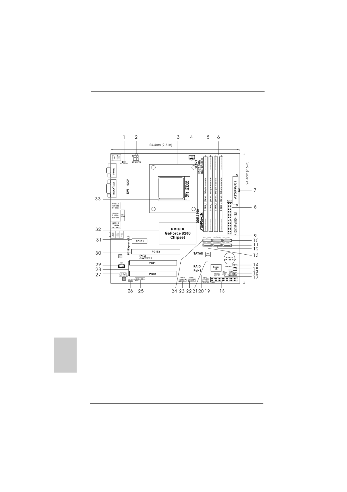
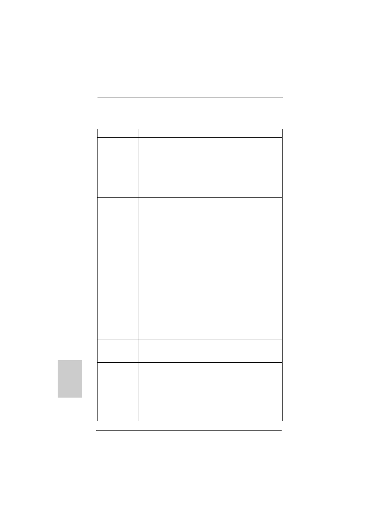
1 PS2_USB_PW1 Jumper 17 DeskExpress Hot Plug Detection Header
2 ATX 12V Power Connector (ATX12V1) (IR1)
3 CPU Heatsink Retention Module 18 Floppy Connector (FLOPPY1)
4 CPU Fan Connector (CPU_FAN1) 19 System Panel Header (PANEL1)
5 2 x 240-pin DDR2 DIMM Slots 20 Chassis Speaker Header (SPEAKER 1)
(Dual Channel A: DDRII_1, DDRII_2; Yellow) 21 SPI Flash Memory (4Mb)
6 2 x 240-pin DDR2 DIMM Slots 22 USB 2.0 Header (USB8_9, Blue)
(Dual Channel B: DDRII_3, DDRII_4; Orange) 23 USB 2.0 Header (USB6_7, Blue)
7 ATX Power Connector (ATXPWR1) 24 Primary SATAII Connector
8 Primary IDE Connector (IDE1, Blue) (SATAII_1 (PORT0))
9 Third SATAII Connector (SATAII_3 (PORT2)) 25 WiFi/E Header (WIFI/E)
10 Fifth SATAII Connector (SATAII_5 (PORT4)) 26 HDMI_SPDIF Header (HDMI_SPDIF1)
11 Sixth SATAII Connector (SATAII_6 (PORT5)) 27 Front Panel Audio Header (HD_AUDIO1)
12 Fourth SATAII Connector (SATAII_4 (PORT3)) 28 PCI Slots (PCI1- 2)
13 Secondary SATAII Connector 29 Internal Audio Connector: CD1 (Black)
(SATAII_2 (PORT1)) 30 PCI Express 2.0 x16 Slot (PCIE2; Green)
14 Clear CMOS Jumper (CLRCMOS1) 31 PCI Express x1 Slot (PCIE1)
15 Chassis Fan Connector (CHA_FAN1) 32 NVIDIA GeForce 8200 Chipset
16 Serial Port Connector (COM1)
ASRock K10N78FullHD-hSLI Motherboard
Page 3
Motherboard LMotherboard L
Motherboard L
Motherboard LMotherboard L
ayoutayout
ayout
ayoutayout
(K10N78F(K10N78F
(K10N78F
(K10N78F(K10N78F
ullHDullHD
ullHD
ullHDullHD
-hSLI R3.0)-hSLI R3.0)
-hSLI R3.0)
-hSLI R3.0)-hSLI R3.0)
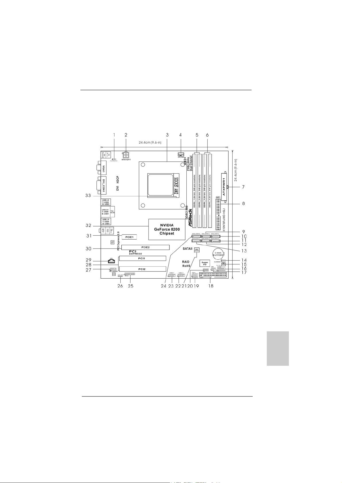
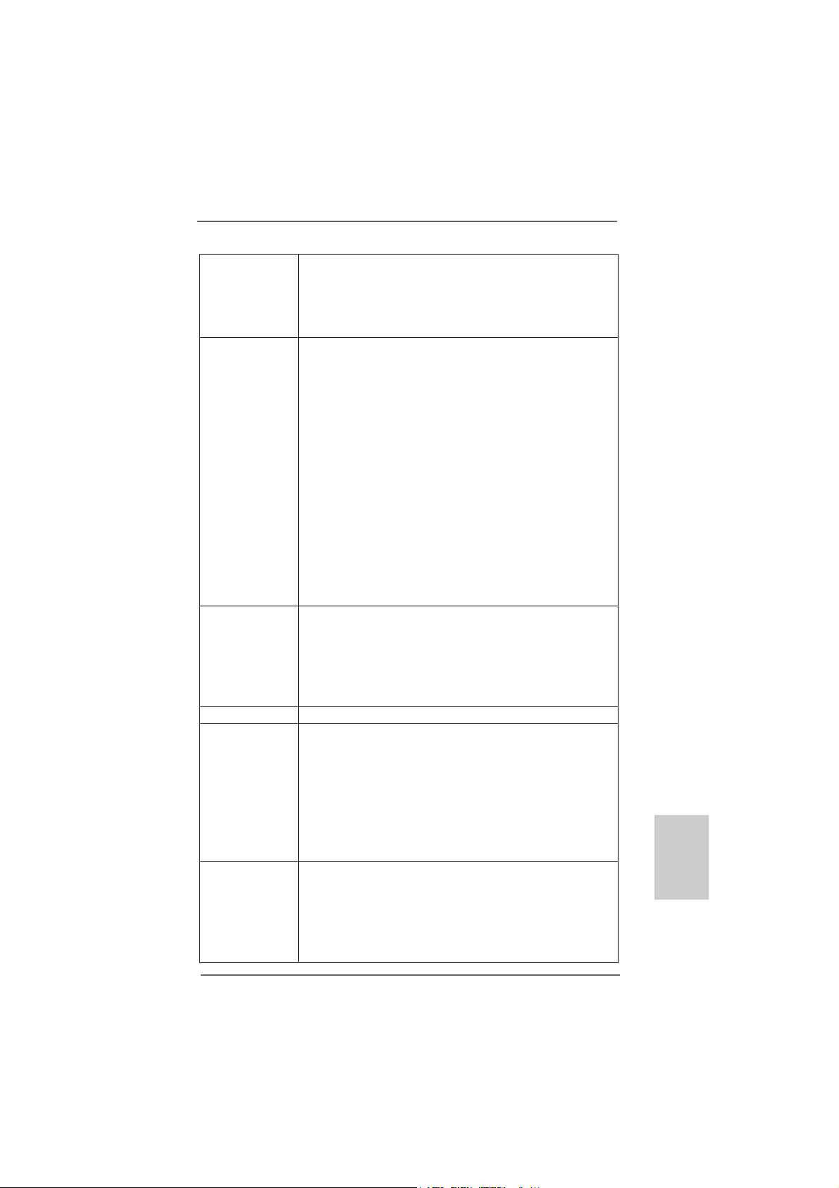
1 PS2_USB_PW1 Jumper 17 DeskExpress Hot Plug Detection Header
2 ATX 12V Power Connector (ATX12V1) (IR1)
3 CPU Heatsink Retention Module 18 Floppy Connector (FLOPPY1)
4 CPU Fan Connector (CPU_FAN1) 19 System Panel Header (PANEL1)
5 2 x 240-pin DDR2 DIMM Slots 20 Chassis Speaker Header (SPEAKER 1)
(Dual Channel A: DDRII_1, DDRII_2; Yellow) 21 SPI Flash Memory (4Mb)
6 2 x 240-pin DDR2 DIMM Slots 22 USB 2.0 Header (USB8_9, Blue)
(Dual Channel B: DDRII_3, DDRII_4; Orange) 23 USB 2.0 Header (USB6_7, Blue)
7 ATX Power Connector (ATXPWR1) 24 Primary SATAII Connector
8 Primary IDE Connector (IDE1, Blue) (SATAII_1 (PORT0))
9 Third SATAII Connector (SATAII_3 (PORT2)) 25 WiFi/E Header (WIFI/E)
10 Fifth SATAII Connector (SATAII_5 (PORT4)) 26 HDMI_SPDIF Header (HDMI_SPDIF1)
11 Sixth SATAII Connector (SATAII_6 (PORT5)) 27 Front Panel Audio Header (HD_AUDIO1)
12 Fourth SATAII Connector (SATAII_4 (PORT3)) 28 PCI Slots (PCI1- 2)
13 Secondary SATAII Connector 2 9 Internal Audio Connector: CD1 (Black)
(SATAII_2 (PORT1)) 30 PCI Express 2.0 x16 Slot (PCIE2; Green)
14 Clear CMOS Jumper (CLRCMOS1) 31 PCI Express x1 Slot (PCIE1)
15 Chassis Fan Connector (CHA_FAN1) 32 NVIDIA GeForce 8200 Chipset
16 Serial Port Connector (COM1)
ASRock K10N78FullHD-hSLI Motherboard
EnglishEnglish
EnglishEnglish
English
33
3
33
Page 4
ASRock 6CH_DVI I/O PlusASRock 6CH_DVI I/O Plus
ASRock 6CH_DVI I/O Plus
ASRock 6CH_DVI I/O PlusASRock 6CH_DVI I/O Plus
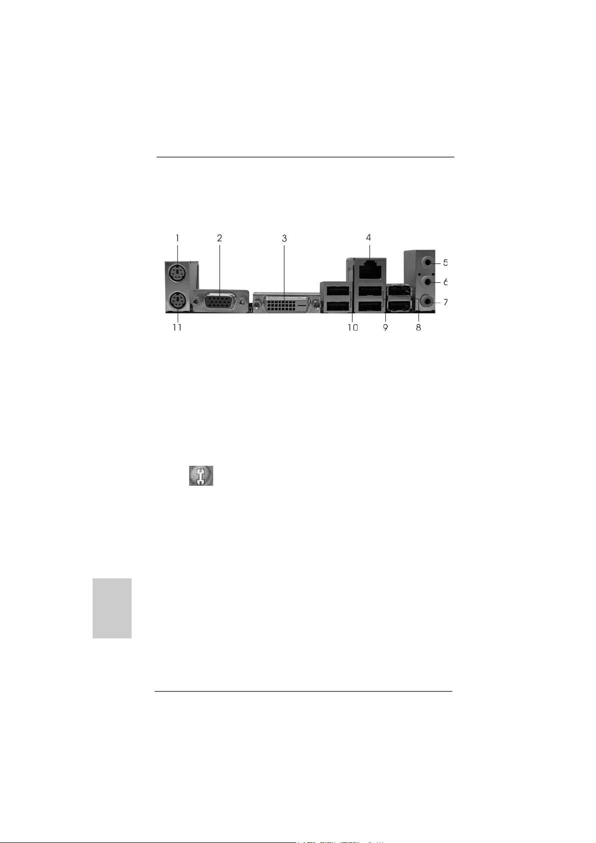
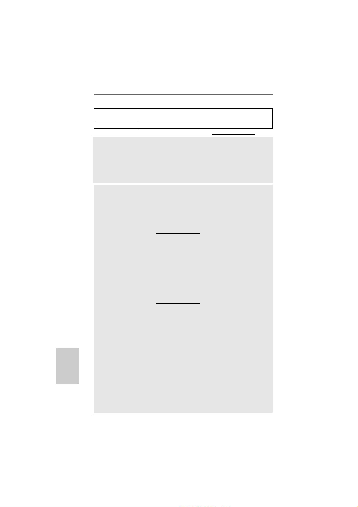
1 PS/2 Mouse Port (Green) * 7 Microphone (Pink)
2 VGA/D-Sub Port 8 USB 2.0 Ports (USB45)
* 3 VGA/DVI-D Port 9 USB 2.0 Ports (USB01)
4 RJ-45 Port 10 USB 2.0 Ports (USB23)
5 Line In (Light Blue) 11 PS/2 Keyboard Port (Purple)
6 Front Speaker (Lime)
* To enable Multi-Streaming function, you need to connect a front panel audio cable to the front
panel audio header. Please refer to below steps for the software setting of Multi-Streaming.
For Windows® XP:
After restarting your computer, you will find “Mixer” tool on your system. Please select “Mixer
ToolBox” , click “Enable playback multi-streaming”, and click “ok”. Choose “2CH” or
English
EnglishEnglish
EnglishEnglish
44
4
44
“4CH” and then you are allowed to select “Realtek HDA Primary output” to use Rear Speaker
and Front Speaker, or select “Realtek HDA Audio 2nd output” to use front panel audio. Then
reboot your system.
For Windows® VistaTM:
After restarting your computer, please double-click “Realtek HD Audio Manager” on the
system tray. Set “Speaker Configuration” to “Quadraphonic” or “Stereo”. Click “Device
advanced settings”, choose “Make front and rear output devices playbacks two different audio
streams simultaneously”, and click “ok”. Then reboot your system.
ASRock K10N78FullHD-hSLI Motherboard
Page 5
1.1.
IntroductionIntroduction
1.
Introduction
1.1.
IntroductionIntroduction
Thank you for purcha sing ASRock K10N78FullHD-hSLI motherboard, a reliable
motherboard produced under ASRock’s consistently stringent quality control. It delivers excellent performance with robust design conforming to ASRock’s commitment to quality and endurance.
This Quick Installation Guide contains introduction of the motherboard and step-bystep installation guide. More detailed information of the motherboard can be found in
the user manual presented in the Support CD.
Because the motherboard specifications and the BIOS software might
be updated, the content of this manual will be subject to change without
notice. In case any modifications of this manual occur, the updated
version will be available on ASRock website without further notice. You
may find the latest VGA cards and CPU support lists on ASRock website
as well. ASRock website http://www.asrock.com
If you require technical support related to this motherboard, please visit
our website for specific information about the model you are using.
www.asrock.com/support/index.asp
1.11.1
PP
ackack
1.1
1.11.1
1 x ASRock K10N78FullHD-hSLI Motherboard
(Micro ATX Form Factor: 9.6-in x 9.6-in, 24.4 cm x 24.4 cm)
1 x ASRock K10N78FullHD-hSLI Quick Installation Guide
1 x ASRock K10N78FullHD-hSLI Support CD
1 x Ultra A TA 66/100/133 IDE Ribbon Cable (80-conductor)
1 x 3.5-in Floppy Drive Ribbon Cable
1 x Serial AT A (SAT A) Data Ca ble (Optional)
1 x Serial AT A (SAT A) HDD Power Cable (Optional)
1 x HDMI_SPDIF Cable (Optional)
1 x “ASRock 6CH_DVI I/O Plus” I/O Shield
age Contentsage Contents
P
ack
age Contents
PP
ackack
age Contentsage Contents
ASRock K10N78FullHD-hSLI Motherboard
EnglishEnglish
EnglishEnglish
English
55
5
55
Page 6
1.21.2
SpecificationsSpecifications
1.2
Specifications
1.21.2
SpecificationsSpecifications
English
EnglishEnglish
EnglishEnglish
Platform - Micro ATX Form Factor: 9.6-in x 9.6-in, 24.4 cm x 24.4 cm
CPU - Support for Socket AM2+ / AM2 processors: AMD Phenom
FX / Phenom / Athlon 64 FX / Athlon 64 X2 Dual-Core / Athlon
X2 Dual-Core / Athlon 64 / Se mpron processor
- AMD LIVE!TM Ready
- Supports AMD’s Cool ‘n’ QuietTM T e chnology
- FSB 2600 MHz (5.2 GT/s) (see CAUTION 1)
- Supports Untied Overclocking Technology (see CAUTION 2)
- Supports Hyper-Tran sport 3.0 (HT 3.0) Technology
Chipset - NVIDIA® GeForce 8200
Memory - Dual Channel DDR2 Memory Technology (see CAUTION 3)
- 4 x DDR2 DIMM slots
- Support DDR2 1066/800/667/533 non-ECC, un-buffered me mory
(see CAUTION 4)
- Max. capacity of system memory: 8GB (see CAUTION 5)
Expansion Slot - 1 x PCI Express 2.0 x16 slot (green @ x16 mode)
- 1 x PCI Express x1 slot
- 2 x PCI slots
- Supports NVIDIA® Hybrid SLI
Graphics - Integrated N VIDIA® GeForce8 Series
- DX10 VGA, Pixel Shader 4.0
- Max. shared memory 512MB (see CAUTION 7)
- Dual VGA Output: support DVI-D and D-Sub ports by
independent display controllers
- Supports HDCP function with DVI-D port
- Supports 1080p Blu-ray (BD) / HD-DVD playback with
DVI-D port (see CAUTION 8)
- NVIDIA® PureVideoTM HD Rea dy
Audio - 5.1 CH Windows® VistaTM Premium Level HD Audio
(ALC662 Audio Codec)
- Chipset embeded HDMI Audio
LAN - K10N78FullHD-hSLI R2.0
Realtek PHY RTL8201CL, speed 10/100 Mb/s
- K10N78FullHD-hSLI R3.0
Realtek Giga PHY R TL8211B, speed 10/100/1000 Mb/s
- Supports Wa ke-On-LAN
Rear Panel I/O ASRock 6CH_DVI I/O Plus
- 1 x PS/2 Mouse Port
- 1 x PS/2 Keyboard Port
TM
(see CAUTION 6)
TM
66
6
66
ASRock K10N78FullHD-hSLI Motherboard
Page 7
- 1 x V GA/D-Sub Port
- 1 x V GA/DVI-D Port (see CAUTION 9)
- 6 x Ready-to-Use USB 2.0 Ports
- 1 x RJ-45 Port
- HD Audio Jack: Line in/Front Speaker/Microphone
Connector - 6 x Serial AT AII 3.0Gb/s connectors, support RAID (RAID 0,
RAID 1, RAID 0+1, RAID 5 and JBOD), NCQ, AHCI a nd
“Hot Plug” functions (see CAUTION 10)
- 1 x ATA133 IDE conne ctor (supports 2 x IDE devices)
- 1 x Floppy connector
- 1 x DeskExpre ss Hot Plug Detection header
- 1 x COM port header
- 1 x HDMI_SPDIF header
- CPU/Chassis FAN connector
- 24 pin A TX power conne ctor
- 4 pin 12V power connector
- CD in header
- Front panel audio header
- 2 x USB 2.0 headers (support 4 USB 2.0 ports)
(see CAUTION 11)
- 1 x WiFi/E header (see CAUTION 12)
BIOS Feature - 4Mb AMI BIOS
- AMI Legal BIOS
- Supports “Plug and Play”
- ACPI 1.1 Compliance Wa ke Up Events
- Supports jumperfree
- SMBIOS 2.3.1 Support
Support CD - Drivers, Utilities, AntiV irus Software (T ri al Version)
Unique Feature - ASRock OC Tuner (see CAUTION 13)
- Intelligent Energy Saver (see CAUTION 14)
- Hybrid Booster:
- CPU Frequency Stepless Control (see CAUTION 15)
- ASRock U-COP (see CAUTION 16)
- Boot Failure Guard (B.F.G.)
- ASRock AM2 Boost: ASRock Patented T echnology to boost
memory performance up to 12.5% (see CAUTION 17)
Hardware - CPU T emperature Sensing
Monitor - Chassis Temperature Sensing
- CPU Fan Ta chometer
- Chassis Fa n Ta chometer
- CPU Quiet Fan
- Voltage Monitoring: +12V, +5V, +3.3V, Vcore
ASRock K10N78FullHD-hSLI Motherboard
EnglishEnglish
EnglishEnglish
English
77
7
77
Page 8
English
EnglishEnglish
EnglishEnglish
88
8
88
OS - Microsoft® Windows® XP / XP Media Center / XP 64-bit /
TM
Vista
/ VistaTM 64-bit compliant
Certifications - FCC, CE, Microsoft® WHQL Certificated
* For detailed product information, please visit our website: http://www.asrock.com
WARNING
Please realize that there is a certain risk involved with overclocking, including
adjusting the setting in the BIOS, applying Untied Overclocking Technology, or using
the third-party overclocking tools. Overclocking may affect your system stability, or
even cause damage to the components and devices of your system. It should be
done at your own risk and expense. We are not responsible for possible damage
caused by overclocking.
CAUTION!
1. If you install AM2 CPU on this motherbord, the system bus speed will be
HT1.0 (2000 MT/s). If you install AM2+ CPU on this motherbord, the system
bus speed will be HT3.0 (up to 5200 MT/s), and the HT Link frequency
depends on the ability of the AM2+ CPU you adopt. Please refer to the CPU
support list on our website for more information.
ASRock website http://www.asrock.com
2. This motherboard supports Untied Overclocking Technology. Please read
“Untied Overclocking Technology” on page 39 for details.
3. This motherboard supports Dual Channel Memory Technology. Before
you implement Dual Channel Memory Technology, make sure to read
the installation guide of memory modules on page 15 for proper
installation.
4. Whether 1066MHz memory speed is supported depends on the AM2+
CPU you adopt. If you want to adopt DDR2 1066 memory module on this
motherboard, please refer to the memory support list on our website for
the compatible memory modules.
ASRock website http://www.asrock.com
5. Due to the operating system limitation, the actual memory size may be
less than 4GB for the reservation for system usage under Windows® XP
and Windows® VistaTM. For Windows® XP 64-bit and Windows® Vista
64-bit with 64-bit CPU, there is no such limitation.
6. Hybrid SLITM feature should depend on the driver from NVIDIA® and it may
be updated in the near future. Currently, the Hybrid SLITM driver in our support CD is beta driver provided by NVIDIA®. As long as we have the latest
Hybrid SLITM driver, we will update it to our website. Please visit our website
for Hybrid SLITM driver in the future. For the current operation procedures,
please refer to “Hybrid SLITM Operation Guide” on page 18.
7. The maximum shared memory size is defined by the chipset vendor
and is subject to change. Please check NVIDIA® website for the latest
information.
8. 1080p Blu-ray (BD) / HD-DVD playback support on this motherboard requires the proper hardware configuration. Please refer to page11 and 12
for the minimum hardware requirement and the passed 1080p Blu-ray
(BD) / HD-DVD films in our lab test.
ASRock K10N78FullHD-hSLI Motherboard
TM
Page 9
9. This DVI-D port for the chipset adopted on this motherboard can support
DVI/HDCP and HDMI format signal. You may use the DVI to HDMI adapter to
convert this DVI-D port to HDMI interface. DVI to HDMI adapter is not bundled
with our product, please refer to the adapter vendor for further information.
10. Before installing SA TAII hard disk to SATAII connector, ple ase read the “SA TAII
Hard Disk Setup Guide” on page 33 to adjust your SATAII hard disk drive to
SATAII mode. You can also connect SATA hard disk to SATAII connector
directly.
11. Power Management for USB 2.0 works fine under Microsoft® Windows
VistaTM 64-bit / VistaTM / XP 64-bit / XP SP1 or SP2.
12. WiFi/E header supports WiFi+AP function with ASRock WiFi-802.11g or
WiFi-802.11n module, an easy-to-use wireless local area network
(WLAN) adapter. It allows you to create a wireless environment and
enjoy the convenience of wireless network connectivity. Please visit our
website for the availability of ASRock WiFi-802.11g or WiFi-802.11n
module. ASRock website http://www.asrock.com
13. It is a user-friendly ASRock overclocking tool which allows you to surveil
your system by hardware monitor function and overclock your hardware
devices to get the best system performance under Windows
environment. Please visit our website for the operation procedures of
ASRock OC Tuner. ASRock website: http://www.asrock.com
14. Featuring an advanced proprietary hardware and software design, Intelligent Energy Saver is one of the options in ASRock OC Tuner. The
voltage regulator can reduce the number of output phases to improve
efficiency when the CPU cores are idle. In other words, it is able to
provide exceptional power saving and improve power efficiency without
sacrificing computing performance. To use Intelligent Energy Saver
function, please enable Cool ‘n’ Quiet option in the BIOS setup in
advance. Please visit our website for the operation procedures of Intelligent Energy Saver. ASRock website: http://www.asrock.com
15. Although this motherboard offers stepless control, it is not recommended to perform over-clocking. Frequencies other than the recommended CPU bus frequencies may cause the instability of the system
or damage the CPU.
16. While CPU overheat is detected, the system will automatically shutdown.
Before you resume the system, please check if the CPU fan on the
motherboard functions properly and unplug the power cord, then plug it
back again. To improve heat dissipation, remember to spray thermal
grease between the CPU and the heatsink when you install the PC
system.
17. This motherboard supports ASRock AM2 Boost overclocking technology. If
you enable this function in the BIOS setup, the memory performance will
improve up to 12.5%, but the effect still depends on the AM2 CPU you
adopt. Enabling this function will overclock the chipset/CPU reference clock.
However, we can not guarantee the system stability for all CPU/DRAM
configurations. If your system is unstable after AM2 Boost function is enabled,
it may not be applicative to your system. You may choose to disable this
function for keeping the stability of your system.
®
®
ASRock K10N78FullHD-hSLI Motherboard
EnglishEnglish
EnglishEnglish
English
99
9
99
Page 10
1.31.3
Minimum Hardware RMinimum Hardware R
1.3
Minimum Hardware R
1.31.3
Minimum Hardware RMinimum Hardware R
TMTM
TM
TMTM
VistaVista
Vista
VistaVista
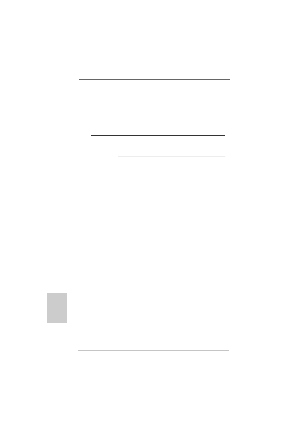
For system integrators and users who purchase this motherboard and
plan to submit Windows® VistaTM Premium 2008 and Basic logo, please f ollow
below table for minimum hardware requirements.
CPU Sempron 2800+
Memory 512MB x 2 Dual Channel (Premium)
VGA DX10 with WDDM Driver
* If you use onboard VGA with total system memory size 512MB and plan to
submit Windows® VistaTM Basic logo, please adjust the shared memory size of
onboard VGA to 64MB. If you use onboard VGA with total system memory size above
512MB and plan to submit Windows® VistaTM Premium or Basic logo, please adjust
the shared memory size of onboard VGA to 128MB or above.
* If you plan to use external graphics card on this motherboard, please refer to Premium
Discrete requirement at http://www.asrock.com
* If the onboard VGA supports DVI, it must also support HDCP function to qualify for
Windows® VistaTM Premium 2008 logo.
* After June 1, 2008, all Windows® VistaTM systems are required to meet above
minimum hardware requirements in order to qualify for Windows® VistaTM Premium
2008 logo.
Premium 2008 and Basic Logo Premium 2008 and Basic Logo
Premium 2008 and Basic Logo
Premium 2008 and Basic Logo Premium 2008 and Basic Logo
512MB Single Channel (Basic)
256MB x 2 Dual Channel (Basic)
DVI with HDCP
equirement Tequirement T
equirement T
equirement Tequirement T
able for Wable for W
able for W
able for Wable for W
indowsindows
indows
indowsindows
®®
®
®®
English
EnglishEnglish
EnglishEnglish
1010
10
1010
ASRock K10N78FullHD-hSLI Motherboard
Page 11
1.41.4
Minimum Hardware Requirement for 1080p Blu-rayMinimum Hardware Requirement for 1080p Blu-ray
1.4
Minimum Hardware Requirement for 1080p Blu-ray
1.41.4
Minimum Hardware Requirement for 1080p Blu-rayMinimum Hardware Requirement for 1080p Blu-ray
(BD) / HD(BD) / HD
(BD) / HD
(BD) / HD(BD) / HD
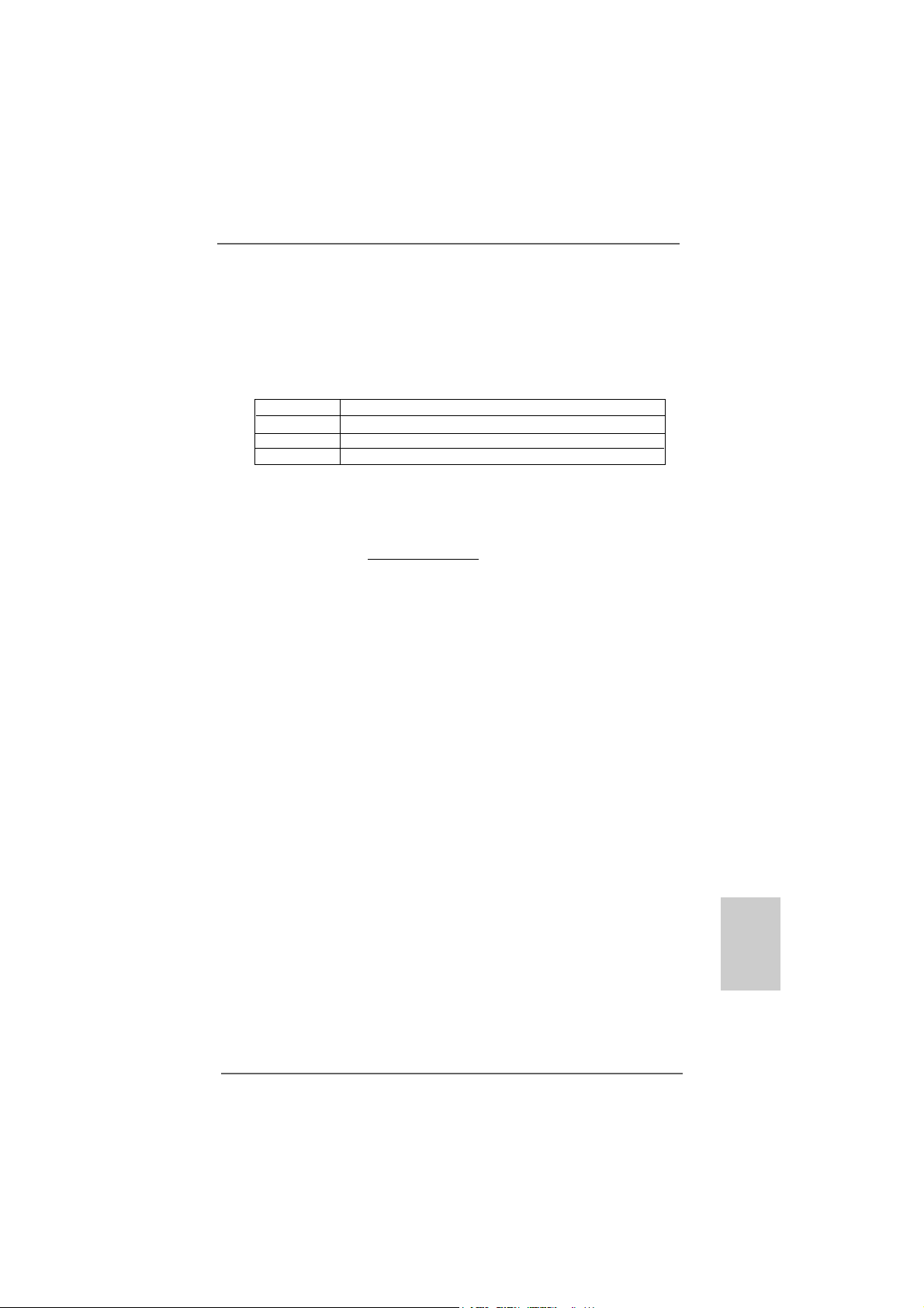
1080p Blu-ray (BD) / HD-DVD playba ck support on this motherboard
requires the proper hardware configuration. Plea se refer to below table
for the minimum hardware requirement.
CP U AMD Phenom X3 8400
VGA Onboard VGA with DVI-D port
Memory Dual Channel DDR2 533, 1GB x 2
Suggested OS Windows® VistaTM or Windows® VistaTM 64
-D-D
VD Playback SupporVD Playback Suppor
-D
VD Playback Suppor
-D-D
VD Playback SupporVD Playback Suppor
tt
t
tt
* Currently, 1080p Blu-ray (BD) / HD-DVD playback is only supported under Windows
VistaTM / VistaTM 64-bit OS. If you install Windows® XP / XP 64-bit OS, the function of
1080p Blu-ray (BD) / HD-DVD playback is not available, please visit our website for
NVIDIA® driver update in the future.
ASRock website http://www.asrock.com
®
ASRock K10N78FullHD-hSLI Motherboard
1111
11
1111
EnglishEnglish
EnglishEnglish
English
Page 12
1.51.5
PP
1.5
1.51.5
assed 1080p Blu-ray (BD) / HDassed 1080p Blu-ray (BD) / HD
P
assed 1080p Blu-ray (BD) / HD
PP
assed 1080p Blu-ray (BD) / HDassed 1080p Blu-ray (BD) / HD
TT
estest
T
est
TT
estest
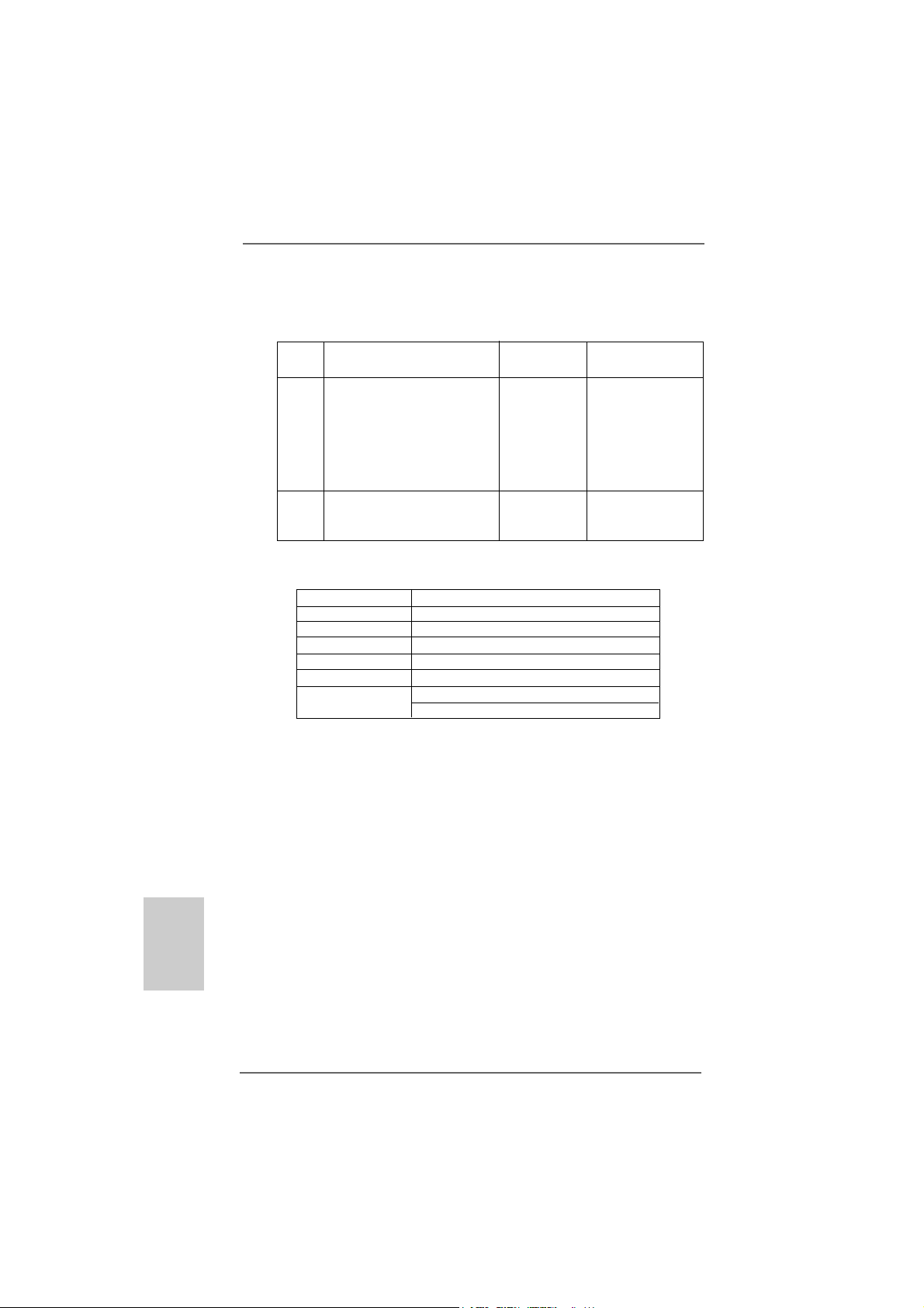
DVD Film Name Format Producer
Type
Blu-ray SWORDFISH VC-1 WB
DVD UNDERWORLD EVOLUTION MPEG-2 SONY
X-MEN III MPEG-4-AVC FOX
SPEED MPEG-4-AVC FOX
CASINO ROYALE MPEG-4-AVC SONY
THE LEAGUE OF MPEG-4-AVC FOX
EXTRAORDINARY GENTLEMEN
HD- KING KONG VC-1 UNIVERSAL
DVD NEW ORLEANS CONCERT MPEG-2 WEA
ONE SIX RIGHT MPEG-2 TERWILLIGER
* MPEG-4-AVC mentioned above refers to the same format of H.264.
* Above passed films are tested under below configuration.
Items Configurations
CPU AMD Phenom X3 8400
VG A Onboard VGA with D VI-D port
Memory Dual Channel DDR2 533, 1GB x 2
OS Windows® VistaTM or Windows® VistaTM 64
Playback Software CyberLink PowerDVD Ultra
DVD Player Blu-ray-DVDRW-LG-GBW-H10N (BD)
HD DVD-HP-TOSD-H802A-01 (HD-D VD)
-D-D
-D
-D-D
VD FVD F
VD F
VD FVD F
ilms in Our Lilms in Our L
ilms in Our L
ilms in Our Lilms in Our L
abab
ab
abab
English
EnglishEnglish
EnglishEnglish
1212
12
1212
ASRock K10N78FullHD-hSLI Motherboard
Page 13
2.2.
InstallationInstallation
2.
Installation
2.2.
InstallationInstallation
This is a Micro ATX form fa ctor (9.6-in x 9.6-in, 24.4 cm x 24.4 cm) motherboard.
Before you install the motherboard, study the configuration of your chassis to ensure that the motherboard fits into it.
Pre-installation PrecautionsPre-installation Precautions
Pre-installation Precautions
Pre-installation PrecautionsPre-installation Precautions
Take note of the following precautions before you install motherboard
components or change any motherboard settings.
Before you install or remove any component, ensure that the
power is switched off or the power cord is detached from the
power supply. Failure to do so may cause severe damage to the
motherboard, peripherals, and/or components.
1. Unplug the power cord from the wall socket before touching any
component.
2. To avoid damaging the motherboard components due to static
electricity, NEVER place your motherboard directly on the carpet or
the like. Also remember to use a grounded wrist strap or touch a
safety grounded object before you handle components.
3. Hold components by the edges and do not touch the ICs.
4. Whenever you uninstall any component, place it on a grounded antistatic pad or in the bag that comes with the component.
5. When placing screws into the screw holes to secure the motherboard
to the chassis, please do not over-tighten the screws! Doing so may
damage the motherboard.
ASRock K10N78FullHD-hSLI Motherboard
1313
13
1313
EnglishEnglish
EnglishEnglish
English
Page 14
2.12.1
CPU InstallationCPU Installation
2.1
CPU Installation
2.12.1
CPU InstallationCPU Installation
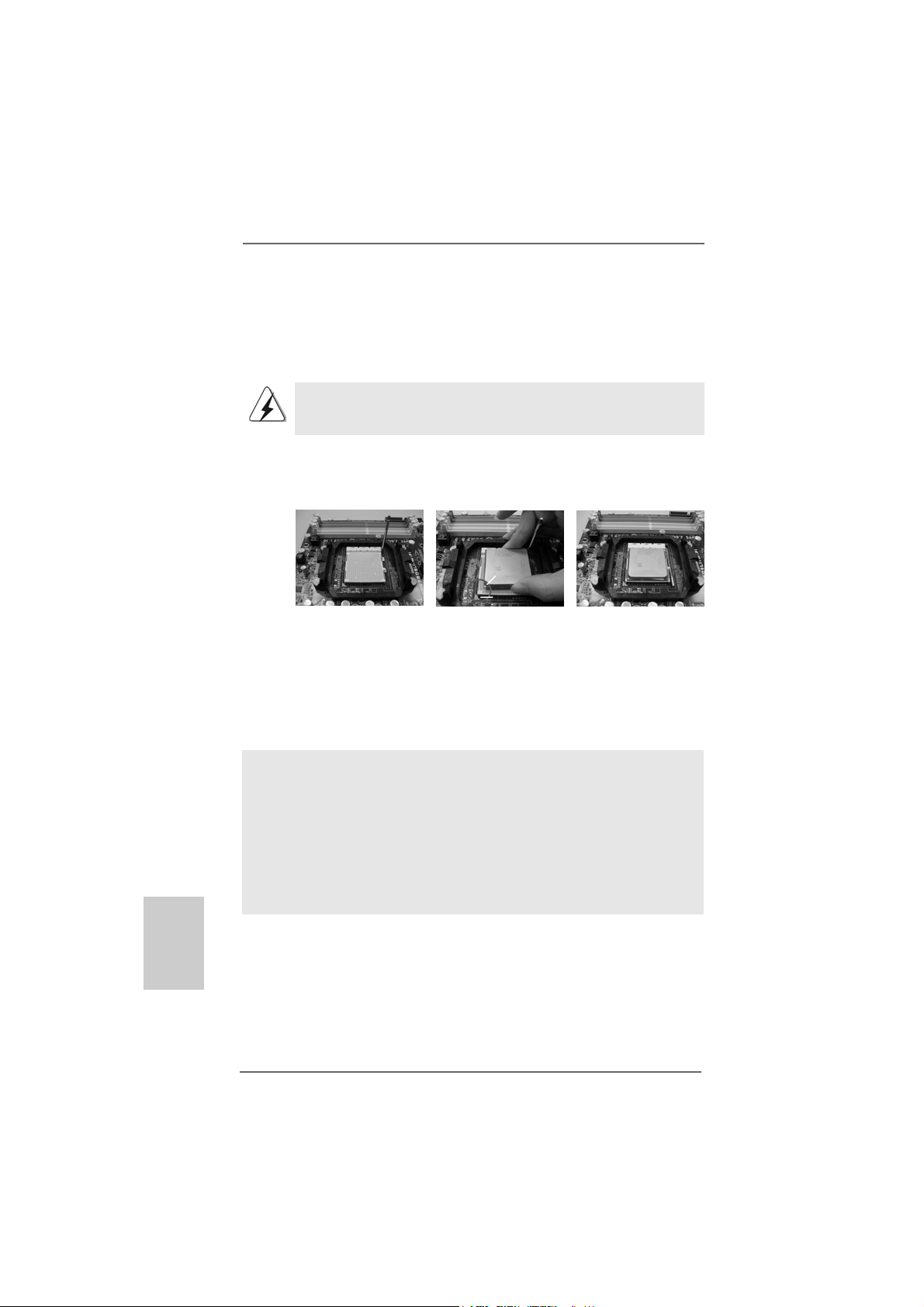
Step 1. Unlock the socket by lifting the lever up to a 90
o
angle.
Step 2. Position the CPU directly above the socket such that the CPU corner with
the golden triangle matches the socket corner with a small triangle.
Step 3. Carefully insert the CPU into the socket until it fits in place.
The CPU fits only in one correct orientation. DO NOT force the CPU
into the socket to avoid bending of the pins.
Step 4. When the CPU is in place, press it firmly on the socket while you push
down the socket lever to secure the CPU. The lever clicks on the side tab
to indicate that it is locked.
Lever 90° Up
CPU Golden Triangle
Socket Corner
Small Triangle
STEP 1:
Lift Up The Socket Lever
2.22.2
Installation of CPU Fan and HeatsinkInstallation of CPU Fan and Heatsink
2.2
Installation of CPU Fan and Heatsink
2.22.2
Installation of CPU Fan and HeatsinkInstallation of CPU Fan and Heatsink
STEP 2 / STEP 3:
Match The CPU Golden Triangle
To The Socket Corner Small
Triangle
STEP 4:
Push Down And Lock
The Socket Lever
English
EnglishEnglish
EnglishEnglish
1414
14
1414
After you install the CPU into this motherboard, it is necessary to install a
larger heatsink and cooling fan to dissipate heat. You also need to spray
thermal grease between the CPU and the heatsink to improve heat
dissipation. Make sure that the CPU and the heatsink are securely fastened and in good contact with each other. Then connect the CPU fan to
the CPU FAN connector (CPU_FAN1, see Page 2/3, No. 4). For proper
installation, please kindly refer to the instruction manuals of the CPU fan
and the heatsink.
ASRock K10N78FullHD-hSLI Motherboard
Page 15
2.3 Installation of Memor2.3 Installation of Memor
2.3 Installation of Memor
2.3 Installation of Memor2.3 Installation of Memor
This motherboard provides four 240-pin DDR2 (Double Data Rate 2) DIMM slots,
and supports Dual Channel Memory Technology. For dual channel configuration,
you always need to install identical (the same brand, speed, size and chip-type)
DDR2 DIMM pair in the slots of the same color. In other words, you have to install
identical DDR2 DIMM pair in Dual Cha nnel A (DDRII_1 a nd DDRII_2; Yellow slots;
see p.2/3 No.5) or identical DDR2 DIMM pair in Dual Channel B (DDRII_3 and
DDRII_4; Orange slots; see p.2/3 No.6), so that Dual Cha nnel Memory Technology
can be a ctivated. This motherboard also allows you to install f our DD R2 DIMMs f or
dual channel configuration, and please install identical DDR2 DIMMs in all four
slots. Y ou may refer to the Dual Channel Memory Configuration Table below.
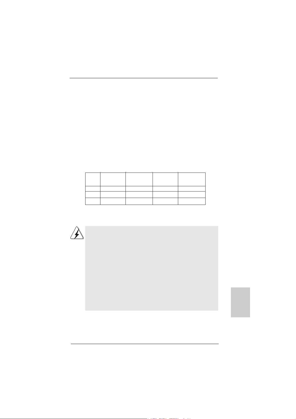
Dual Channel Memory Configurations
DDRII_1 DDRII_2 DDRII_3 DDRII_4
(Y ellow Slot) (Yellow Slot) (Orange Slot) (Orange Slot)
(1) Populated Populated - (2) - - Populated Populated
(3)* Populated Populated Populated Populated
y Modules (DIMM)y Modules (DIMM)
y Modules (DIMM)
y Modules (DIMM)y Modules (DIMM)
* For the configuration (3), please install identical DD R2 DIMM s in all f our slots.
1. If you want to install two memory modules, for optimal compatibility and reliability, it is recommended to install them in the slots of
the same color. In other words, install them either in the set of
yellow slots (DDRII_1 and DDRII_2), or in the set of orange slots
(DDRII_3 and DDRII_4).
2. If only one memory module or three memory modules are installed in the DDR2 DIMM slots on this motherboard, it is unable to
activate the Dual Channel Memory Technology.
3. If a pair of memory modules is NOT installed in the same Dual
Channel, for example, installing a pair of memory modules in
DDRII_1 and DDRII_3, it is unable to activate the Dual Channel
Memory Technology .
4. It is not allowed to install a DDR memory module into DDR2 slot;
otherwise, this motherboard and DIMM may be damaged.
EnglishEnglish
EnglishEnglish
English
ASRock K10N78FullHD-hSLI Motherboard
1515
15
1515
Page 16
Installing a DIMMInstalling a DIMM
Installing a DIMM
Installing a DIMMInstalling a DIMM
Please make sure to disconnect power supply before adding or
removing DIMMs or the system components.
Step 1. Unlock a DIMM slot by pressing the retaining clips outward.
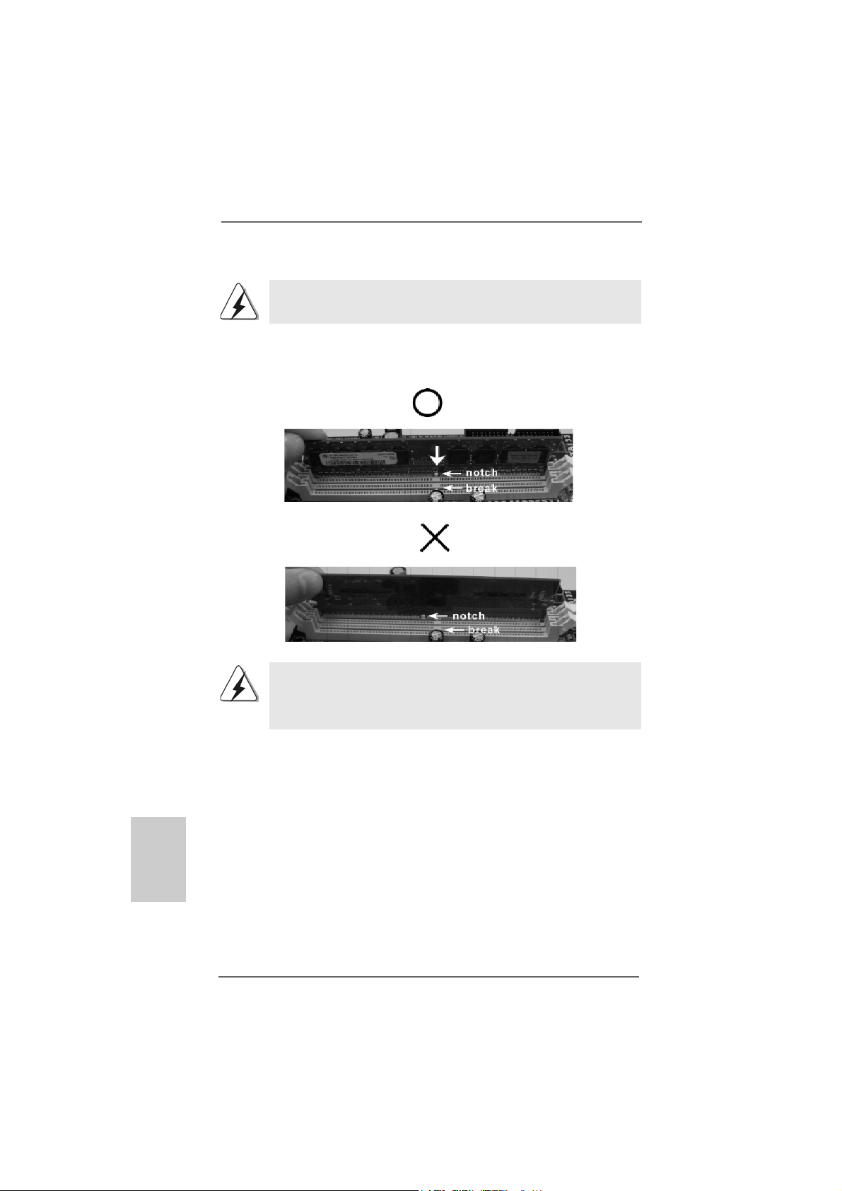
Step 2. Align a DIMM on the slot such that the notch on the DIMM matches the bre a k
on the slot.
English
EnglishEnglish
EnglishEnglish
1616
16
1616
The DIMM only fits in one correct orientation. It will cause permanent
damage to the motherboard and the DIMM if you force the DIMM into the
slot at incorrect orientation.
Step 3. Firmly insert the DIMM into the slot until the retaining cli ps at both ends fully
snap back in place and the DIMM is properly seated.
ASRock K10N78FullHD-hSLI Motherboard
Page 17

2.4 Expansion Slots (PCI and PCI Express Slots)2.4 Expansion Slots (PCI and PCI Express Slots)
2.4 Expansion Slots (PCI and PCI Express Slots)
2.4 Expansion Slots (PCI and PCI Express Slots)2.4 Expansion Slots (PCI and PCI Express Slots)
There are 2 PCI slots and 2 PCI Express slots on this motherboard.
PCI slots: PCI slots are used to install expansion cards that have the 32-bit PCI
interface.
PCIE slots: PCIE1 (PCIE x1 slot) is used for PCI Express cards with x1 la ne width
cards, such as Gigabit LAN card, SATA2 card, etc.
PCIE2 (PCIE x16 slot) is used for PCI Express cards with x16 lane
width graphics cards.
Installing an expansion cardInstalling an expansion card
Installing an expansion card
Installing an expansion cardInstalling an expansion card
Step 1. Before installing the expansion card, please make sure that the power supply
is switched off or the power cord is unplugged. Plea se read the documentation
of the expansion card a nd ma ke necessary hardware
settings for the card before you start the installation.
Step 2. Remove the bracket facing the slot that you intend to use. Keep the screws
for later use.
Step 3. Align the card connector with the slot and press firmly until the card is com-
pletely seated on the slot.
Step 4. Fasten the card to the chassis with screws.
ASRock K10N78FullHD-hSLI Motherboard
1717
17
1717
EnglishEnglish
EnglishEnglish
English
Page 18

TMTM
TM
2.52.5
2.5
2.52.5
Hybrid SLIHybrid SLI
Hybrid SLI
Hybrid SLIHybrid SLI
TMTM
Operation Guide Operation Guide
Operation Guide
Operation Guide Operation Guide
This motherboard supports N VIDIA® Hybrid SLITM feature. Hybrid SLITM technology, ba sed
on NVIDIA®’ s industry-leading SLITM technology , delivers multi-GPU (graphics proce ssing
unit) benefits when an N VIDIA® motherboard GPU is combined with a n N VIDIA® discrete
GPU. Hybrid SLITM technology today includes two primary features: GeForce® Boost
and HybridPowerTM. Hybrid SLITM increase s gra phics perf orma nce with GeForce® Boost
and provides intelligent power ma nagement with HybridPowerTM. Currently, N VIDIA® Hybrid
SLITM Technology is only supported with Windows® Vista
TM
OS, and is not available with
other OS. Please visit our website f or the driver update in the future.
GeForce® Boost
GeForce® Boost turbocharges the performance of NVIDIA® discrete GPU when
combined with NVIDIA® motherboard GPU. When GeForce® Boost is enabled, the
motherboard GPU and the discrete GPU share the rendering load by rendering
different frames of an image. Installing NVIDIA® Hybrid SLITM-enabled graphics card
into NVIDIA® Hybrid SLITM-enabled motherboard allows you to enjoy additive
performance.
English
EnglishEnglish
EnglishEnglish
HybridPower
HybridPowerTM enables users to switch off the discrete GPU when the higher
processing power of the discrete GPU is not required and use the motherboard
GPU for non intensive graphics applications. Switching off the discrete GPU not
only lowers the total system power consumption for everyday computing tasks like
browsing the Web, word processing, or watching HD videos but also lowers total
system noise.
Minimum System Configuration for Hybrid SLIMinimum System Configuration for Hybrid SLI
Minimum System Configuration for Hybrid SLI
Minimum System Configuration for Hybrid SLIMinimum System Configuration for Hybrid SLI
TM
TMTM
TM
TMTM
For best Hybrid SLITM benefits, the following minimum system configuration is
recommended. Please refer to below ta ble f or the mini mum system configuration f or
GeForce® Boost mode and HybridPowerTM mode.
GeForce® Boost
CPU AMD Phenom CPU
Memory Dual Channel DDR2 800, 1024MB x 2
256MB or 512MB shared memory for motherboard GPU
Suggested OS Windows® VistaTM or Windows® VistaTM 64
HybridPower
CP U AMD Athlon X2 3800+ CPU
Memory Dual Channel DDR2 667, 1024MB x 2
Suggested OS Windows® VistaTM or Windows® VistaTM 64
TM
256MB or 512MB shared memory for motherboard GPU
1818
18
1818
ASRock K10N78FullHD-hSLI Motherboard
Page 19
TMTM
TM
Supported PCI Express Card for Hybrid SLISupported PCI Express Card for Hybrid SLI
Supported PCI Express Card for Hybrid SLI
Supported PCI Express Card for Hybrid SLISupported PCI Express Card for Hybrid SLI
TMTM
GeForce® Boost and HybridPowerTM features are supported only with certain set of discrete
GPUs. Please refer to our website f or the graphics cards update in the future.
For GeForce® Boost
Vendor Chipset Model Driver
NVIDIA Ge Fo r ce 8 40 0 GS Giga byte GV-NX84G256H 174.83
GeForce 8 400GS Foxconn FV-N84SM2DT 174.83
GeForce 8400GS Leadtek WinFast PX8400 GS TDH 174.83
GeForce 8500GT Gigabyte GV-NX85T256H 174.83
For HybridPower
Vendor Chipset Model Driver
NVIDIA GeForce 9800GX2 ASUS PCIE-ASUS-9800GX2/512M174.83
TM
Enjoy the benefit of NVIDIAEnjoy the benefit of NVIDIA
Enjoy the benefit of NVIDIA
Enjoy the benefit of NVIDIAEnjoy the benefit of NVIDIA
®®
®
®®
Hybrid SLI Hybrid SLI
Hybrid SLI
Hybrid SLI Hybrid SLI
TMTM
TM
TMTM
T o en joy Hybrid SLITM feature, plea se refer to below installation a nd setup procedures
according to the mode you pla n to use.
For users using single monitor: If you connect the monitor to the
motherboard GPU, you can switch between GeForce® Boost mode (Boost
Performance) and HybridPowerTM mode (Save Power). If you connect the
monitor to the card GPU, you can choose GeForce® Boost mode (Boost
Performance) only.
®®
®
A. GeForceA. GeForce
A. GeForce
A. GeForceA. GeForce
®®
Boost Boost
Boost
Boost Boost
Step 1. Install one compatible PCI Express graphics card to PCIE2 slot (green). For
the proper installation procedures, plea se refer to section “Expansion Slots”.
Step 2. Connect the monitor cable to the correspondent connector on the PCI
Express graphics card on PCIE2 slot.
Step 3. Boot your system. Press <F2> to enter BIOS setup. Enter “Advanced” screen,
and enter “Chipset Settings”. Then set the option “Hybrid SLI” to [256MB] or
[512MB].
If you want to use onboard VGA output, after step 1 to 3, please follow
below steps:
A. Set up the BIOS option “Primary Graphics Display” to [Onboard], and
save your BIOS change and exit BIOS setup.
B. Power off your system.
C. Switch your monitor cable to the connector on the I/O shield.
After reboot your system, you are allowed to switch between GeForce
Boost mode (Boost Performance) and HybridPower
according to your request.
TM
mode (Save Power)
®
EnglishEnglish
EnglishEnglish
English
ASRock K10N78FullHD-hSLI Motherboard
1919
19
1919
Page 20
English
EnglishEnglish
EnglishEnglish
Step 4. Boot into OS. Install Hybrid SLITM driver from our support CD to your system.
Hybrid SLITM driver is in the following path of ASRock support CD:
(There are two ASRock support CD in the motherboard gift box pack, please
choose the one for Windows® VistaTM / VistaTM 64-bit.)
..\Drivers\Hybrid SLI driver\Vista
* Currently, Hybrid SLITM driver only has VistaTM 32 version, please visit our
website for future update.
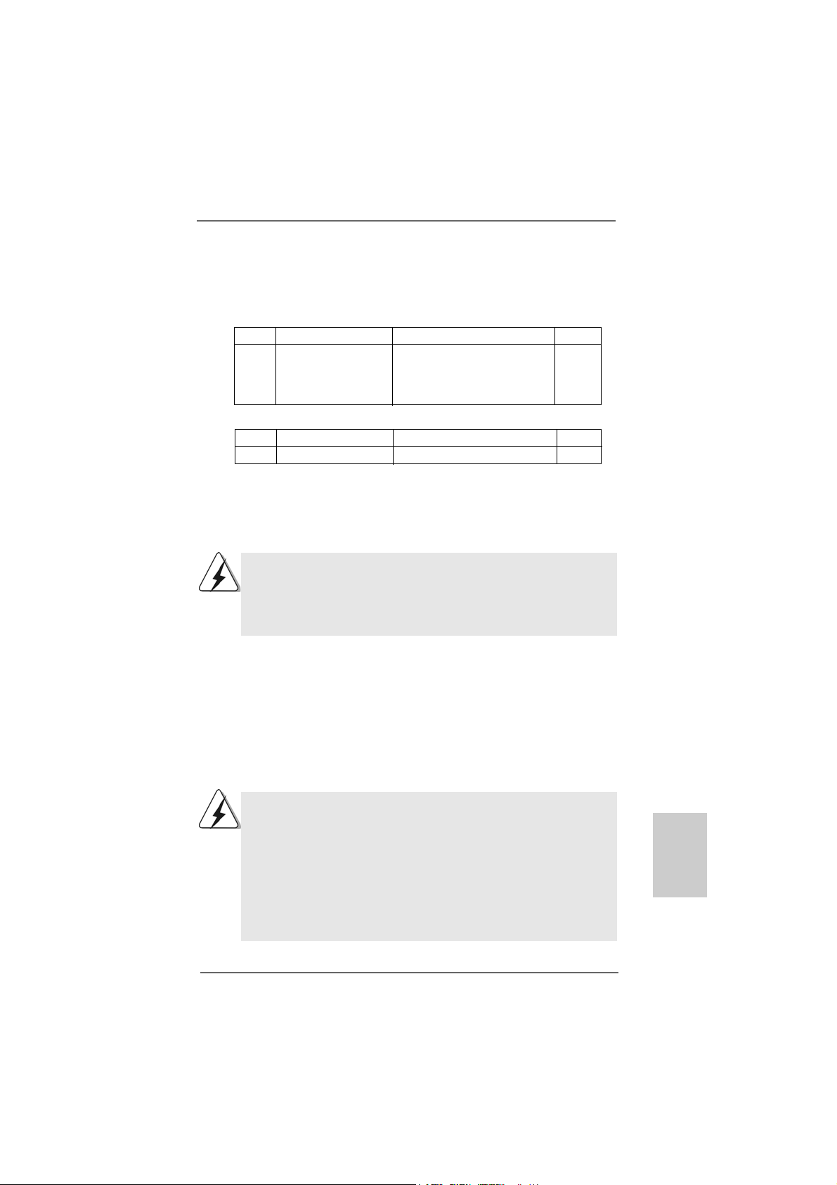
Step 5. Restart your computer. Then you will find the Hybrid icon on your Windows
taskbar.
Step 6. The default setting is GeForce® Boost mode (Boost Performance). You do not
need to adjust the setup anymore.
TMTM
TM
B. HybridPowerB. HybridPower
B. HybridPower
B. HybridPowerB. HybridPower
TMTM
Step 1. Install one compatible PCI Express graphics card to PCIE2 slot (green). For
the proper installation procedures, plea se refer to section “Expansion Slots”.
Step 2. Boot your system. Press <F2> to enter BIOS setup. Enter “Advanced” screen,
and enter “Chipset Settings”. Then set the option “Hybrid SLI” to [256MB] or
[512MB]. And set the option “Pri mary Graphics Display” to [Onboard].
Step 3. Save your BIOS change and exit BIOS setup.
Step 4. Power off your system.
Step 5. Connect the monitor cable to the correspondent connector on the I/O shield.
Step 6. Boot into OS. Install Hybrid SLITM driver from our support CD to your system.
Hybrid SLITM driver is in the following path of ASRock support CD:
(There are two ASRock support CD in the motherboard gift box pack, please
choose the one for Windows® VistaTM / VistaTM 64-bit.)
..\Drivers\Hybrid SLI driver\Vista
* Currently, Hybrid SLITM driver only has VistaTM 32 version, please visit our
website for future update.
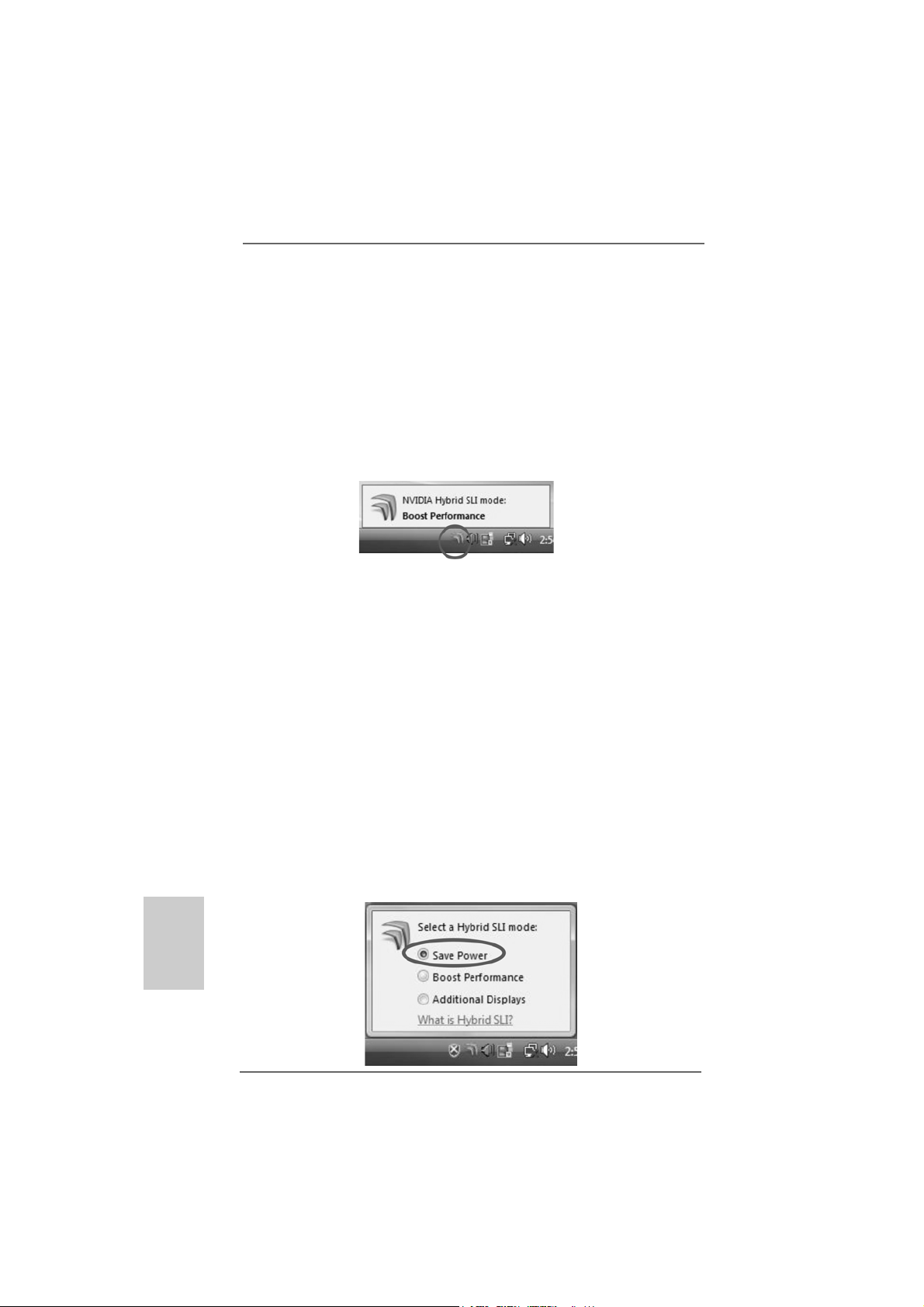
Step 7. Restart your computer. Then you will find the Hybrid icon on your Windows
tas kbar. Please click the icon and select the item “Save Power”.
®
®
2020
20
2020
ASRock K10N78FullHD-hSLI Motherboard
Page 21
Step 8. Click the desktop. Then your system is switched to HybridPowerTM mode
(Save Power).
C. Dual MonitorsC. Dual Monitors
C. Dual Monitors
C. Dual MonitorsC. Dual Monitors
Step 1. Install one compatible PCI Express graphics card to PCIE2 slot (green). For
the proper installation procedures, plea se refer to section “Expansion Slots”.
Step 2. Boot your system. Press <F2> to enter BIOS setup. Enter “Advanced” screen,
and enter “Chipset Settings”. Then set the option “Share Me mory” to [32MB],
[64MB], [128MB], [256MB] or [512MB].
Step 3. Connect one monitor cable to the correspondent connector on the I/O shield.
Connect the other monitor cable to the correspondent connector on the PCI
Express graphics card on PCIE2 slot.
Step 4. Boot into OS. Install Hybrid SLITM driver from our support CD to your system.
Hybrid SLITM driver is in the following path of ASRock support CD:
(There are two ASRock support CD in the motherboard gift box pack, please
choose the one for Windows® VistaTM / VistaTM 64-bit.)
..\Drivers\Hybrid SLI driver\Vista
* Currently, Hybrid SLITM driver only has VistaTM 32 version, please visit our
website for future update.
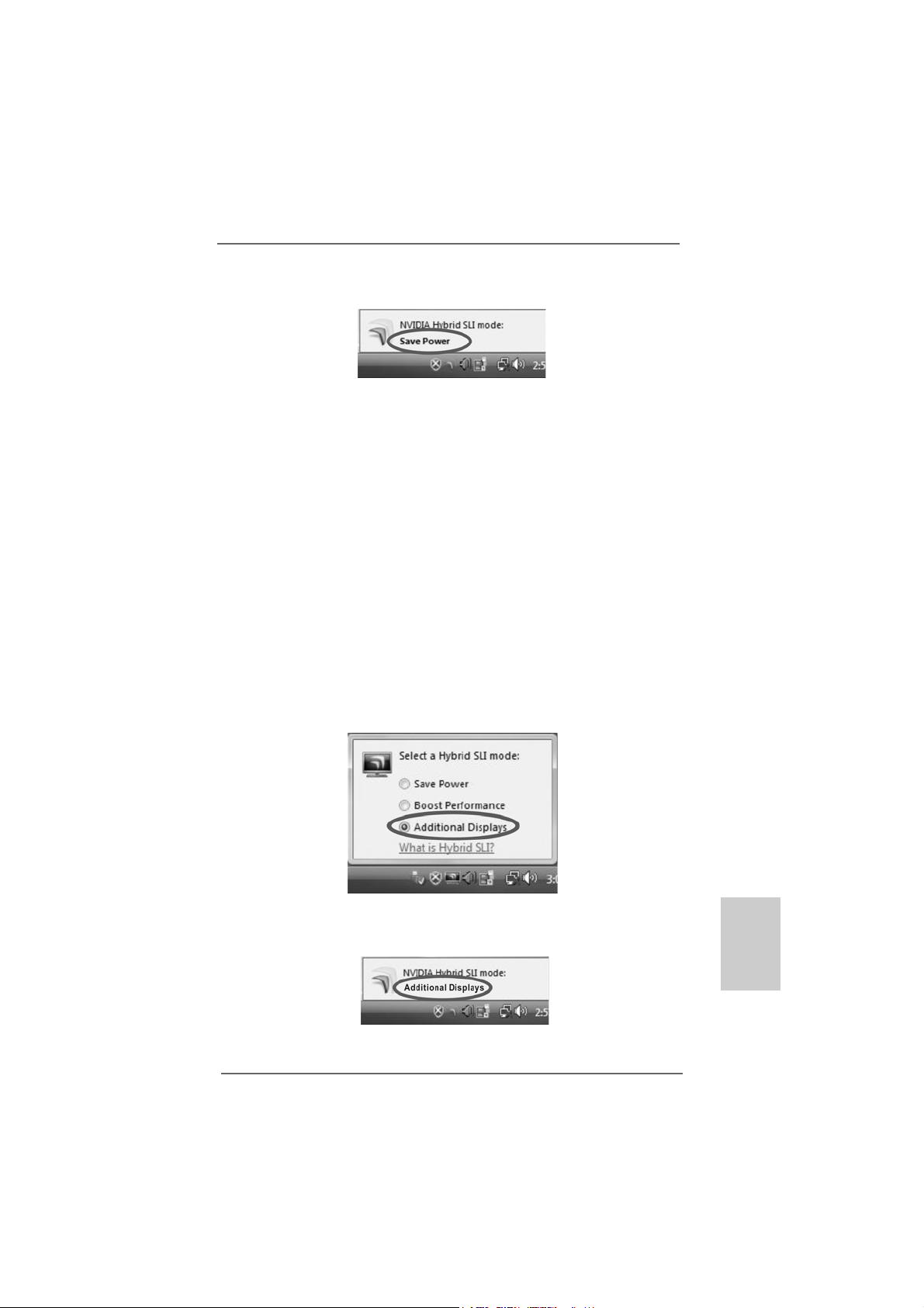
Step 5. Restart your computer. Then you will find the Hybrid icon on your Windows
taskbar. Plea se click the icon and select the item “Additional Displays”.
®
Step 6. Click the desktop. Then your system is switched to Dual Monitors mode
(Additional Displays).
ASRock K10N78FullHD-hSLI Motherboard
2121
21
2121
EnglishEnglish
EnglishEnglish
English
Page 22
2.6 Dual Monitor and Surround Display Features2.6 Dual Monitor and Surround Display Features
2.6 Dual Monitor and Surround Display Features
2.6 Dual Monitor and Surround Display Features2.6 Dual Monitor and Surround Display Features
Dual Monitor Feature
This motherboard supports dual monitor feature. With the internal dual VGA output
support (DVI-D and D-Sub), you ca n e a sily en joy the benefits of dual monitor feature
without installing any a dd-on VGA card to this motherboard. This motherboard also
provides independent display controllers for D VI-D a nd D-Sub to support dual V GA
output so that DVI-D a nd D-sub can drive sa me or dif ferent display contents. To enable
dual monitor feature, plea se follow the below ste ps:
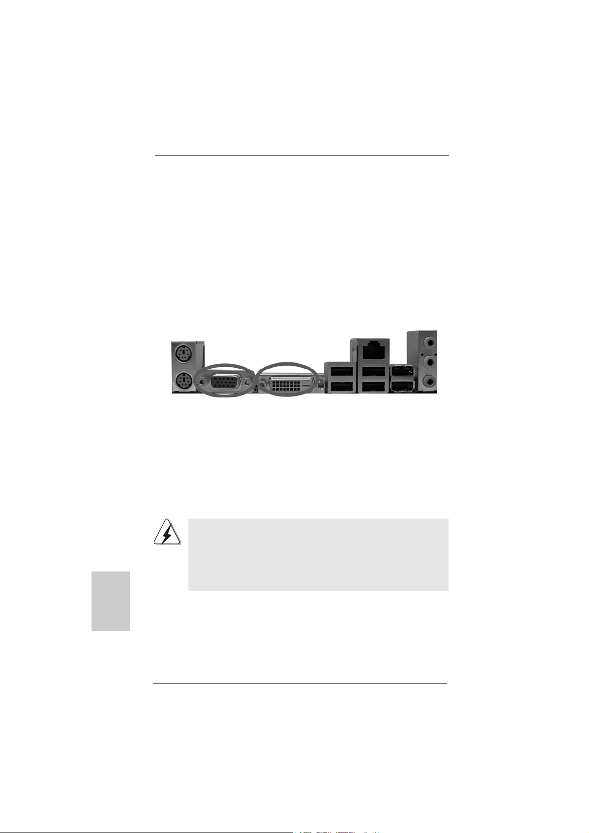
1. Connect the DVI-D monitor ca ble to the VGA/D VI-D port on the I/O panel of this
motherboard. Connect the D-Sub monitor cable to the VGA/D-Sub port on the I/O
panel of this motherboard.
VGA/D-Sub port VGA/D VI-D port
2. If you have installed onboard V GA driver from our support CD to your system
already , you can freely enjoy the benefits of dual monitor function provided by
V GA/DVI-D and VGA/D-Sub ports with this motherboard after your syste m
boots. If you haven’t installed onboard V GA driver yet, please in stall onboard
V GA driver from our support CD to your system a nd re start your computer.
Then you can start to use dual monitor function provided by VGA/DVI-D and
V GA/D-Sub ports with this motherboard.
English
EnglishEnglish
EnglishEnglish
2222
22
2222
1. When you playback HDCP-protected video from Blu-ray (BD) or
HD-DVD disc, the content will be displayed only in one of the two
monitors instead of both monitors.
2. This motherboard does not support dual monitor feature under DOS
because in this situation, the VGA/DVI-D output is not available. There
is no such limitation under Windows® OS.
ASRock K10N78FullHD-hSLI Motherboard
Page 23

Surround Display Feature
This motherboard supports surround display upgrade. With the internal dual VGA
output support (DVI-D and D-Sub) a nd the external a dd-on PCI Express VGA card, you
can easily enjoy the benefits of surround display feature. Plea se refer to the f ollowing
steps to set up a surround display environment:
1. Install the NVIDIA® PCI Express VGA card to PCI Express slot. Please refer to
page 17 for proper expansion card in stallation procedures f or details.
2. Connect the DVI-D monitor ca ble to the VGA/D VI-D port on the I/O panel of this
motherboard. Connect the D-Sub monitor cable to the VGA/D-Sub port on the I/O
panel of this motherboard.
3. Boot your system. Press <F2> to enter BIOS setup. Enter “Share Memory”
option to adjust the memory capability to [32MB], [64MB], [128MB], [256MB] or
[512MB] to enable the function of VGA/D-sub. Please make sure that the value you
select is less than the total capability of the system memory. If you do not adjust
the BIOS setup, the default value of “Share Memory”, [Auto], will disable
V GA/D-Sub function when the add-on VGA card is inserted to this motherboard.
4. Install the onboard V GA driver and the add-on PCI Express VGA card driver to
your system. If you have installed the onboard VGA driver a nd the a dd-on PCI
Express VGA card driver already, there is no need to install them again.
5. Set up a multi-monitor display.
For Windows® XP / XP 64-bit OS:
Right click the desktop, choose “Properties”, and select the “Settings” ta b so
that you can adjust the parameters of the multi-monitor according to the steps
below.
A. Click the “Identify” button to display a large number on each monitor.
B. Right-click the display icon in the Display Properties dialog that you wish
to be your primary monitor, and then select “Primary”. When you use
multiple monitors with your card, one monitor will always be Primary, and
all additional monitors will be designated as Secondary .
C. Select the display icon identified by the number 2.
D. Click “Extend my Windows desktop onto this monitor”.
E. Right-click the display icon and select “Attached”, if necessary.
F . Set the “Screen Re solution” a nd “Color Quality” as a ppropri ate f or the
second monitor. Click “Apply” or “OK” to apply these new values.
G. Repeat steps C through E for the di aplay icon identified by the number
one, two, three and four.
For Windows® VistaTM / VistaTM 64-bit OS:
Right click the desktop, choose “Personalize”, a nd sele ct the “Display
Settings” tab so that you can adjust the parameters of the multi-monitor
according to the steps below.
EnglishEnglish
EnglishEnglish
English
ASRock K10N78FullHD-hSLI Motherboard
2323
23
2323
Page 24

A. Click the number ”2” icon.
B. Click the items “This is my main monitor” and “Extend the desktop onto
this monitor”.
C. Click “OK” to save your change.
D. Repeat steps A through C for the display icon identified by the number
three and four.
6. Use Surround Display. Click and drag the display icons to positions re pre senting
the physical setup of your monitors that you would like to use. The placement
of display icons determines how you move items from one monitor to another.
HDCP Function with DVI-D Port
HDCP function is supported with DVI-D port on this motherboard. To
use HDCP function with this motherboard, you need to adopt the
monitor that supports HDCP function a s well. Theref ore, you ca n
enjoy the superior display quality with high-definition HDCP encryption
contents. Please refer to below in struction f or more details about HDCP
function.
What is HDCP?
HDCP stands f or High-Ba ndwidth Digital Content Protection, a
specification developed by Intel® for protecting digital entertainment
content that uses the DVI interface. HDCP is a copy protection
scheme to eliminate the possibility of intercepting digital data
midstream between the video source, or transmitter - such as a
computer, DVD player or set-top box - and the digital display, or
receiver - such as a monitor, television or projector. In other words,
HDCP specification is designed to protect the integrity of content as it
is being transmitted.
English
EnglishEnglish
EnglishEnglish
2424
24
2424
Products compatible with the HDCP scheme such a s DVD players,
satellite and cable HDTV set-top-boxes, as well a s few entertainment PCs requires a secure connection to a compliant display. Due
to the increase in manufacturers employing HDCP in the ir equipment,
it is highly recommended that the HDTV or LCD monitor you purchase
is compatible.
ASRock K10N78FullHD-hSLI Motherboard
Page 25
2.7 HDMI Audio F2.7 HDMI Audio F
2.7 HDMI Audio F
2.7 HDMI Audio F2.7 HDMI Audio F
The D VI-D port for the chipset adopted on this motherboard ca n support DVI/HDCP a nd
HDMI format signal. You may use the DVI to HDMI ada pter to convert the DVI-D port to
HDMI interface. Please follow below steps to enable HDMI audio function a ccording to
the OS you install.
1. DVI to HDMI adapter is not bundled with this motherboard, please
refer to the adapter vendor for further information.
2. If you install the DVI-D monitor instead of the HDMI monitor on this
motherboard and enable HDMI audio function, the film you play
may pause sometimes.
For Windows® XP / XP 64-bit OS
Step 1: Set up BIOS.
A. Enter BIOS SETUP UTILITY Advanced screen Chipset Configuration.
B. Set the option “OnBoard HDMI HD Audio” to [Auto].
Step 2: Install HDMI audio driver to your system.
Install “Onboard HDMI HD Audio Driver” from ASRock Support CD to your system .
Step 3: Reboot your system.
After you reboot the system, the HDMI audio function is available.
After HDMI audio driver is installed, the OS default will output the
audio signal through HDMI audio. Therefore, the onboard audio jack
will not function.
unction Operation Guideunction Operation Guide
unction Operation Guide
unction Operation Guideunction Operation Guide
For Windows® VistaTM / VistaTM 64-bit OS
Step 1: Set up BIOS.
A. Enter BIOS SETUP UTILITY Advanced screen Chipset Configuration.
B. Set the option “OnBoard HDMI HD Audio” to [Auto].
Step 2: Enter Windows® to set up your system manually.
A. Click “Start” button, select “Settings”, and then click “Control Panel”.
B. Click “Hardware and Sound”, a nd click “Sound”.
C. Change the default setting “Spea ker” to “Digital Output Device (HDMI)”.
D. Click “OK” to finish the setting.
Step 3: Reboot your system.
After you reboot the system, the HDMI audio function is available.
ASRock K10N78FullHD-hSLI Motherboard
2525
25
2525
EnglishEnglish
EnglishEnglish
English
Page 26
2.82.8
Jumpers SetupJumpers Setup
2.8
Jumpers Setup
2.82.8
Jumpers SetupJumpers Setup
The illustration shows how jumpers are setup.
When the jumper cap is placed on pins, the
jumper is “Short”. If no jumper cap is pla ced on
pins, the jumper is “Open”. The illustration
shows a 3-pin jumper whose pin1 and
pin2 are “Short” when jumper cap is pla ced on
these 2 pins.
Jumper Setting
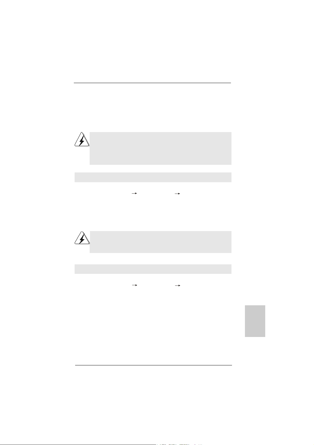
PS2_USB_PW1 Short pin2, pin3 to enable
(see p.2/3, No. 1) +5VSB (standby) for PS/2 or
USB wake up events.
Note: T o select +5VSB, it requires 2 Amp and higher sta ndby current provided by
power supply.
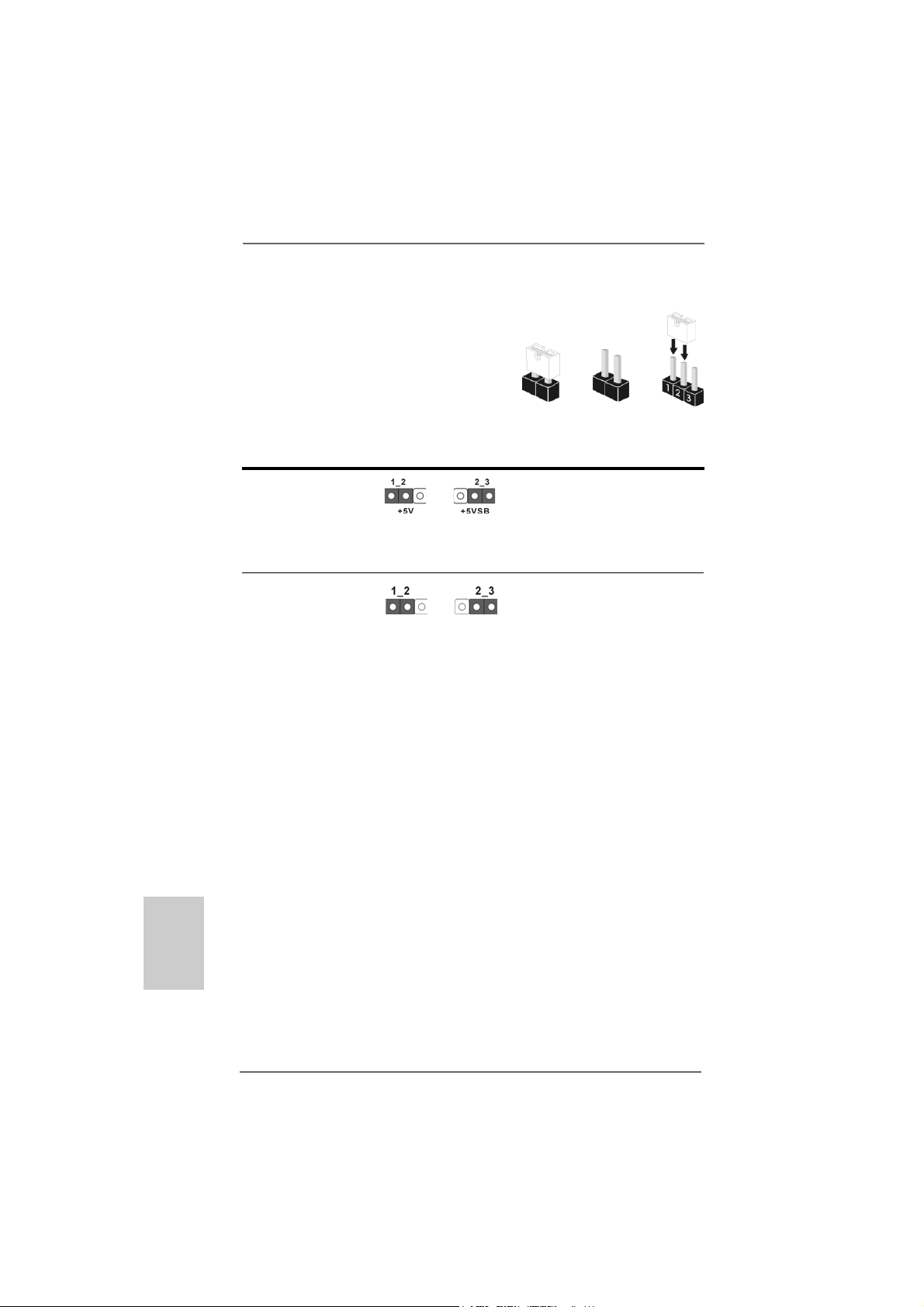
Clear CMOS Jumper
(CLRCMOS1)
(see p.2/3, No. 14)
Note: CLRCMOS1 allows you to clear the data in CMOS. The data in CMOS includes
system setup information such as system password, date, time, and system
setup parameters. To clear and reset the system parameters to default setup,
please turn of f the computer and unplug the power cord from the power supply.
After waiting for 15 seconds, use a jumper ca p to short pin2 and pin3 on CLRCMOS1
for 5 seconds. However , please do not clear the CMOS right after you update the
BIOS. If you need to clear the CMOS when you just finish updating the BIOS, you
must boot up the system first, and then shut it down before you do the clearCMOS action.
Clear CMOSDefault
OpenShort
English
EnglishEnglish
EnglishEnglish
2626
26
2626
ASRock K10N78FullHD-hSLI Motherboard
Page 27
2.9 Onboard Headers and Connectors2.9 Onboard Headers and Connectors
2.9 Onboard Headers and Connectors
2.9 Onboard Headers and Connectors2.9 Onboard Headers and Connectors
Onboard headers and connectors are NOT jumpers. Do NOT place
jumper caps over these headers and connectors. Placing jumper
caps over the headers and connectors will cause permanent damage of the motherboard!
•
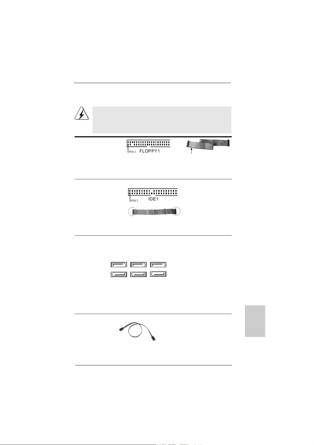
Floppy Connector
(33-pin FLOPPY1)
(see p.2/3 No. 18)
the red-striped side to
Pin1
Note: Make sure the red-striped side of the cable is plugged into Pin1 side of the
connector.
Primary IDE connector (Blue)
(39-pin IDE1, see p.2/3 No. 8)
connect the blue end
to the motherboard
80-conductor ATA 66/100/133 cable
connect the black end
to the IDE devices
Note: Please refer to the instruction of your IDE device vendor for the details.
Serial AT AII Connectors These six Serial A T AII (SAT AII)
(SATAII_1 (PORT0): connectors support SA T AII
see p.2/3, No. 24) or SATA hard disk f or internal
(SATAII_2 (PORT1): storage devices. The current
see p.2/3, No. 13) SATAII interface allows up to
(SATAII_3 (PORT2): 3.0 Gb/s data tra n sfer rate.
see p.2/3, No. 9)
(SATAII_4 (PORT3):
see p.2/3, No. 12)
(SATAII_5 (PORT4):
see p.2/3, No. 10)
(SATAII_6 (PORT5):
see p.2/3, No. 11)
SATAII_1 SATAII_3 SATAII_5
(PORT 0) (PORT 2) (PORT 4)
SATAII_2 SATAII_4 SATAII_6
(PORT 1) (PORT 3) (PORT 5)
Serial AT A (SA T A) Either end of the SATA data ca ble
Data Cable can be connected to the SATA /
(Optional) SATAII hard disk or the SA TAII
connector on the motherboard.
EnglishEnglish
EnglishEnglish
English
ASRock K10N78FullHD-hSLI Motherboard
2727
27
2727
Page 28
Serial ATA (SATA) Please connect the black end of
Power Cable SAT A power ca ble to the power
(Optional) connector on each drive. Then
connect to the SATA
HDD power connector
connect to
the power
supply
connect the white end of SATA
power cable to the power
connector of the power supply.
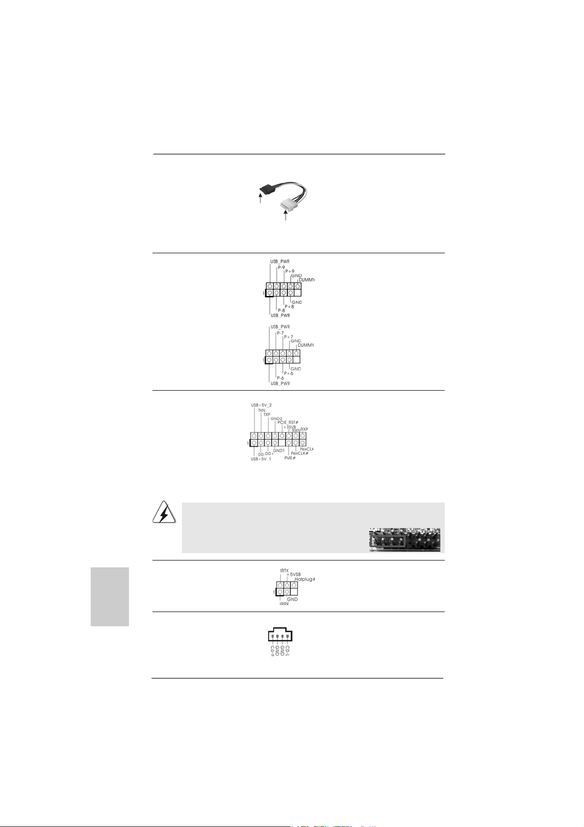
USB 2.0 Headers Besides six default USB 2.0
(9-pin USB8_9) ports on the I/O panel, there are
(see p.2/3 No. 22) two USB 2.0 headers on this
motherboard. Each USB 2.0
header can support two USB
2.0 ports.
(9-pin USB6_7)
(see p.2/3 No. 23)
WiFi/E Header This header supports WiFi+AP
(15-pin WIFI/E) function with ASRock
(see p.2/3 No. 25) WiFi-802.11g or WiFi-802.11n
module, an easy-to-use wireless
local area network (WLAN)
adapter. It allows you to create a
wireless environment and enjoy the
convenience of wireless network
connectivity.
If you don’t plan to use WiFi+AP functin on this motherboard, this header can be
used as a 4-Pin USB 2.0 header to support one USB 2.0 port. To connect the
4-Pin USB device cable to this header, please refer to
this picture for proper installation.
English
EnglishEnglish
EnglishEnglish
2828
28
2828
DeskExpress Hot Plug Dete ction This header supports the Hot
Header Plug detection function for
(5-pin IR1) ASRock DeskExpress.
(see p.2/3 No. 17)
Internal Audio Connectors This connector allows you
(4-pin CD1) to receive stereo audio input
(CD1: see p.2/3 No. 29) from sound sources such as
CD1
a CD-ROM, D VD-ROM, TV
tuner card, or MPEG card.
ASRock K10N78FullHD-hSLI Motherboard
Page 29
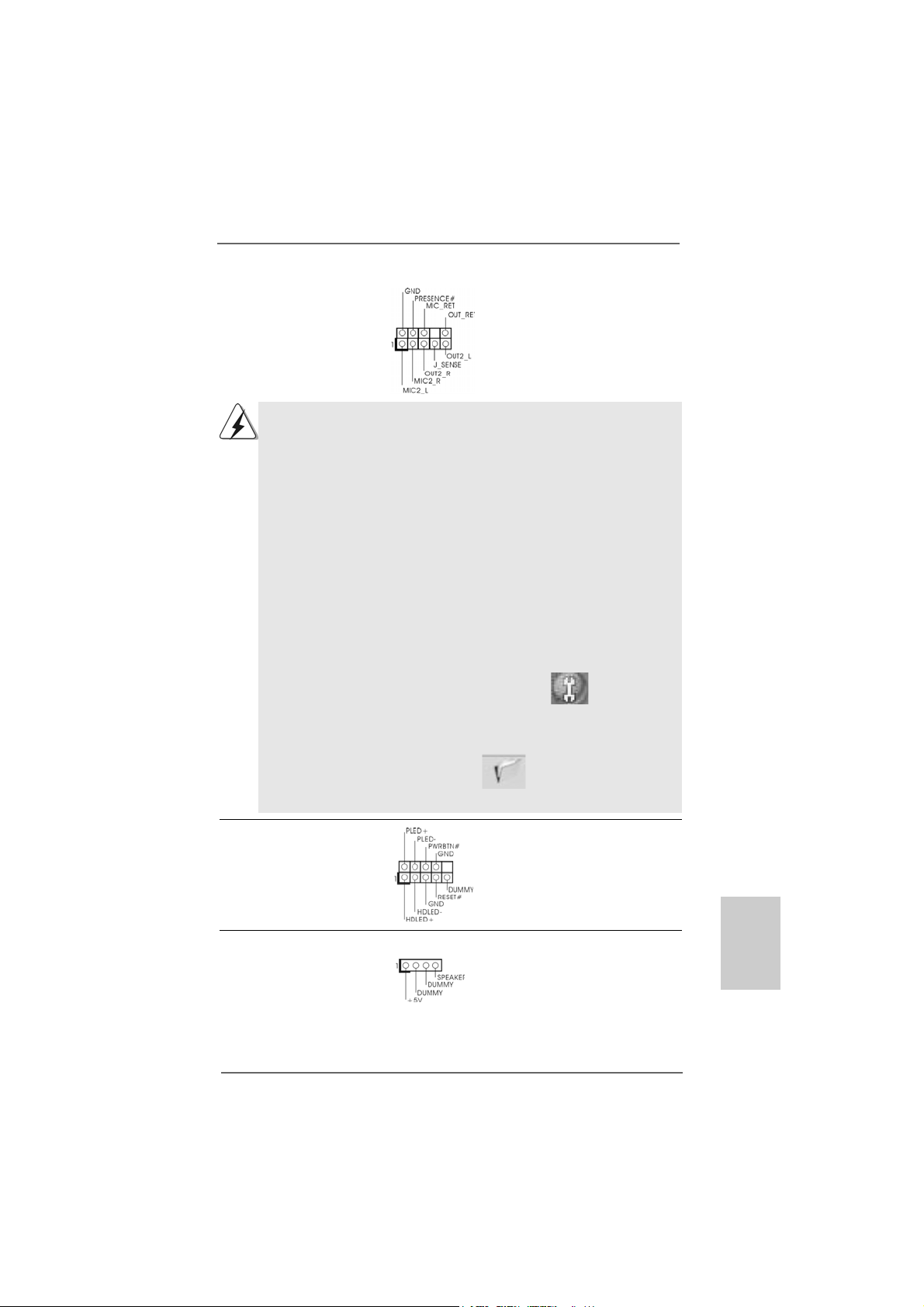
Front Panel Audio Header This is a n interface for the front
(9-pin HD_AUDIO1) panel audio cable that allows
(see p.2/3, No. 27) convenient connection and
control of audio devices.
1. High Definition Audio supports Jack Sensing, but the panel wire on
the chassis must support HDA to function correctly. Please follow the
instruction in our manual and chassis manual to install your system.
2. If you use AC’97 audio panel, please install it to the front panel audio
header as below:
A. Connect Mic_IN (MIC) to MIC2_L.
B. Connect Audio_R (RIN) to OUT2_R and Audio_L (LIN) to OUT2_L.
C. Connect Ground (GND) to Ground (GND).
D. MIC_RET and OUT_RET are for HD audio panel only. You don’t
need to connect them for AC’97 audio panel.
E. Enter BIOS Setup Utility. Enter Advanced Settings, and then select
Chipset Configuration. Set the Front Panel Control option from
[Auto] to [Enabled].
F. Enter Windows system. Click the icon on the lower right hand
taskbar to enter Realtek HD Audio Manager.
For Windows
Click “Audio I/O”, select “Connector Settings” , choose
“Disable front panel jack detection”, and save the change by
clicking “OK”.
For Windows® VistaTM / VistaTM 64-bit OS:
Click the right-top “Folder” icon , choose “Disable front
®
XP / XP 64-bit OS:
panel jack detection”, and save the change by clicking “OK”.
System Panel Hea der This hea der accommodates
(9-pin PANEL1) several system front panel
(see p.2/3 No. 19) functions.
Chassis Spea ker He ader Please connect the chassis
(4-pin SPEAKER 1) speaker to this header.
(see p.2/3 No. 20)
ASRock K10N78FullHD-hSLI Motherboard
2929
29
2929
EnglishEnglish
EnglishEnglish
English
Page 30
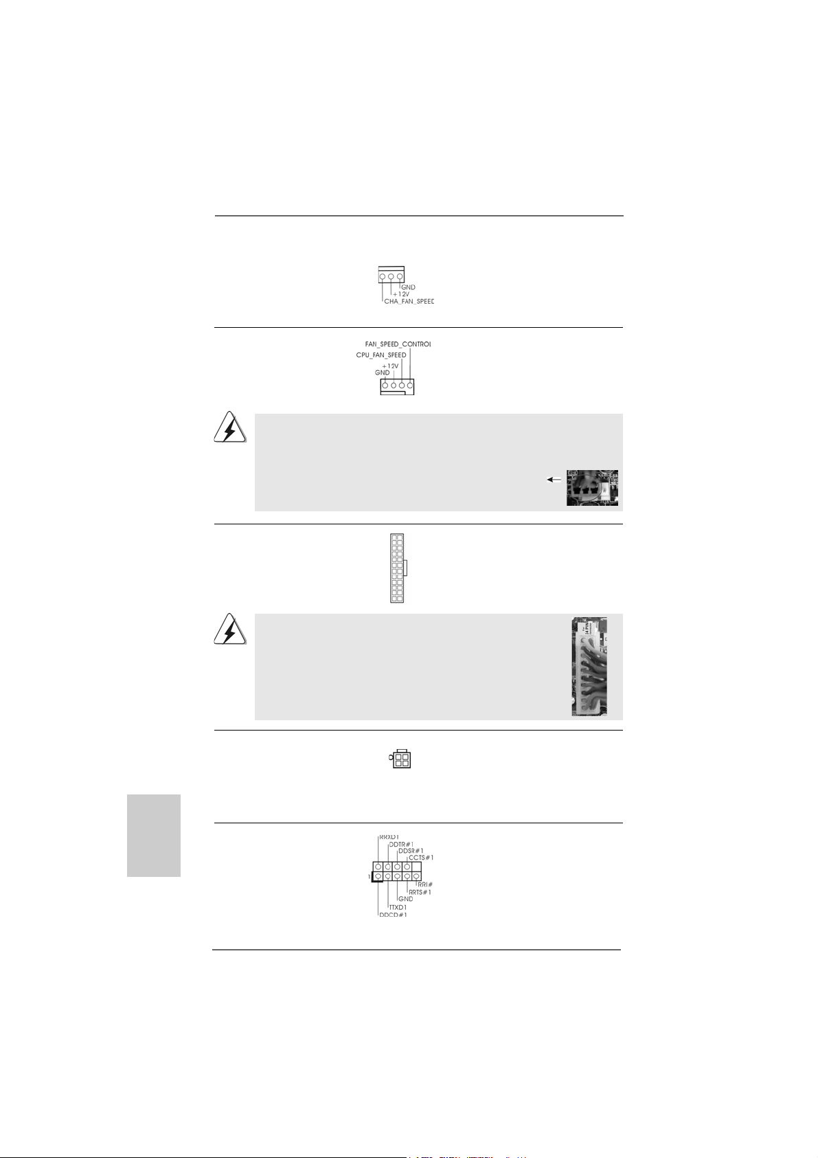
Chassis Fa n Connector Please conne ct a chassis fan
(3-pin CHA_FAN1) cable to this connector and
(see p.2/3 No. 15) match the black wire to the
ground pin.
CPU Fan Connector Please connect the CPU fa n
(4-pin CPU_FAN1) cable to this connector and
(see p.2/3 No. 4) match the black wire to the
ground pin.
1 2 3 4
Though this motherboard provides 4-Pin CPU fan (Quiet Fan) support, the 3-Pin
CPU fan still can work successfully even without the fan speed control function.
If you plan to connect the 3-Pin CPU fan to the CPU fan connector on this
motherboard, please connect it to Pin 1-3.
Pin 1-3 Connected
3-Pin Fan Installation
English
EnglishEnglish
EnglishEnglish
ATX Power Conne ctor Please connect an A TX power
(24-pin ATXPWR1) supply to this connector.
(see p.2/3 No. 7)
Though this motherboard provides 24-pin ATX power connector,
12 124
13
12
it can still work if you adopt a traditional 20-pin ATX power supply.
To use the 20-pin ATX power supply, please plug your power
supply along with Pin 1 and Pin 13.
20-Pin ATX Power Supply Installation
1
ATX 12V Power Connector Please note that it is necessary
(4-pin ATX12V1) to connect a power supply with
(see p.2/3 No. 2) ATX 12V plug to this conne ctor.
Failing to do so will cause power
up failure.
Serial port Header This COM1 header
(9-pin COM1) supports a serial port module.
(see p.2/3 No.16)
24
13
3030
30
3030
ASRock K10N78FullHD-hSLI Motherboard
Page 31

HDMI_SPDIF Header HDMI_SPDIF header, providing
(3-pin HDMI_SPDIF1) SPDIF audio output to HDMI V GA
(see p.2/3 No. 26) card, allows the system to
connect HDMI Digital TV/
projector/LCD devices. Please
connect the HDMI_SPDIF
connector of HDMI V GA card to
this header.
HDMI_SPDIF Cable Please connect the black end (A)
(Optional) of HDMI_SPDIF cable to the
C
B
A
HDMI_SPDIF header on the
motherboard. Then connect the
white end (B or C) of
HDMI_SPDIF cable to the
HDMI_SPDIF connector of HDMI
VGA card.
A. black end B. white end (2-pin) C. white end (3-pin)
12
1
24
13
EnglishEnglish
EnglishEnglish
English
3131
31
3131
ASRock K10N78FullHD-hSLI Motherboard
Page 32

2.10 HDMI_SPDIF Header Connection Guide2.10 HDMI_SPDIF Header Connection Guide
2.10 HDMI_SPDIF Header Connection Guide
2.10 HDMI_SPDIF Header Connection Guide2.10 HDMI_SPDIF Header Connection Guide
HDMI (High-Definition Multi-media Interfa ce) is an all-digital audio/video specification,
which provides an interface between any compatible digital audio/video source,
such as a set-top box, DVD player, A/V receiver and a compatible digital audio or
video monitor, such as a digital television (DTV). A complete HDMI system requires a
HDMI VGA card and a HDMI ready motherboard with a HDMI_SPDIF header. This
motherboard is equipped with a HDMI_SPDIF header, which provides SPDIF audio
output to HDMI VGA card, allows the system to connect HDMI Digital TV/projector/
LCD devices. To use HDMI function on this motherboard, please carefully follow the
below steps.
•
Step 1. Install the HDMI VGA card to the PCI Express Graphics slot on this
motherboard. For the proper installation of HDMI VGA card, please refer
to the installation guide on page 17.
Step 2. Connect the black end (A) of HDMI_SPDIF cable to the
HDMI_SPDIF header (HDMI_SPDIF1, yellow, see page 2/3,
No. 26) on the motherboard.
Make sure to correctly connect the HDMI_SPDIF cable to the motherboard and the
HDMI VGA card according to the same pin definition. For the pin definition of
HDMI_SPDIF header and HDMI_SPDIF cable connectors, please refer to page 31.
For the pin definition of HDMI_SPDIF connectors on HDMI VGA card, please refer to
the user manual of HDMI VGA card vendor. Incorrect connection may cause
permanent damage to this motherboard and the HDMI VGA card.
Step 3. Connect the white end (B or C) of HDMI_SPDIF cable to the HDMI_SPDIF
connector of HDMI VGA card. (There are two white ends (2-pin and 3-pin)
on HDMI_SPDIF cable. Please choose the appropriate white end according
to the HDMI_SPDIF connector of the HDMI VGA card you install.
English
EnglishEnglish
EnglishEnglish
3232
32
3232
white end
(2-pin) (B)
Please do not connect the white end of HDMI_SPDIF cable to the wrong connector
of HDMI VGA card or other VGA card. Otherwise, the motherboard and the
VGA card may be damaged. For example, this picture shows the wrong
example of connecting HDMI_SPDIF cable to the fan connector of PCI
Express VGA card. Please refer to the VGA card user manual for
connector usage in advance.
white end
(3-pin) (C)
Step 4. Connect the HDMI output connector on HDMI VGA card to
HDMI device, such as HDTV. Please refer to the user manual
of HDTV and HDMI VGA card vendor for detailed connection
procedures.
Step 5. Install HDMI VGA card driver to your system.
ASRock K10N78FullHD-hSLI Motherboard
Page 33

2.112.11
SASA
TT
2.11
2.112.11
Before installing SA TAII hard disk to your computer, please carefully read below SATAII
hard disk setup guide. Some default setting of SA TAII hard disks may not be at SATAII
mode, which operate with the best performance. In order to enable SATAII function,
please f ollow the below instruction with dif ferent vendors to correctly a djust your SATAII
hard disk to SATAII mode in advance; otherwise, your SAT AII hard disk may fail to run at
SAT AII mode.
Western Digital
If pin 5 and pin 6 are shorted, SATA 1.5Gb/s will be enabled.
On the other hand, if you want to enable SATAII 3.0Gb/s, please remove the jumpers
from pin 5 and pin 6.
SAMSUNG
If pin 3 and pin 4 are shorted, SATA 1.5Gb/s will be enabled.
On the other hand, if you want to enable SATAII 3.0Gb/s, please remove the jumpers
from pin 3 and pin 4.
AII Hard Disk Setup GuideAII Hard Disk Setup Guide
SA
T
AII Hard Disk Setup Guide
SASA
TT
AII Hard Disk Setup GuideAII Hard Disk Setup Guide
HITACHI
Please use the Feature Tool, a DOS-bootable tool, for changing various A TA feature s.
Please visit HITACHI’s website for details:
http://www.hitachigst.com/hdd/support/download.htm
The above examples are just for your reference. For different SATAII hard
disk products of different vendors, the jumper pin setting methods may not
be the same. Please visit the vendors’ website for the updates.
ASRock K10N78FullHD-hSLI Motherboard
3333
33
3333
EnglishEnglish
EnglishEnglish
English
Page 34

2.122.12
Serial ASerial A
2.12
Serial A
2.122.12
Serial ASerial A
InstallationInstallation
Installation
InstallationInstallation
This motherboard adopts NVIDIA® GeForce 8200 chipset that supports Seri al ATA
(SATA) / Serial AT AII (SATAII) hard dis ks a nd RAID (RAID 0, RAID 1, RAID 0+1, RAID 5
and JBOD) functions. You may install SATA / SATAII hard disks on this motherboard
for internal storage devices. This section will guide you to in stall the SATA / SA TAII
hard disks.
STEP 1: Install the SATA / SAT AII hard disk s into the drive bays of your chassis.
STEP 2: Connect the SATA power ca ble to the SAT A / SATAII hard disk.
STEP 3: Connect one end of the SATA data cable to the motherboard’s SAT AII
connector.
STEP 4: Connect the other end of the SATA data cable to the SAT A / SA TAII hard
disk.
TT
A (SAA (SA
TT
A (SA
A (SAA (SA
A) / Serial AA) / Serial A
T
A) / Serial A
TT
A) / Serial AA) / Serial A
T
TT
1. If you plan to use RAID 0, RAID 1 or JBOD function, you need to install at
least 2 SATA / SATAII hard disks. If you plan to use RAID 5 function, you
need to install 3 SATA / SATAII hard disks. If you plan to use RAID 0+1
function, you need to install 4 SATA / SATAII hard disks.
2. Under non-RAID mode, SATAII_5 (PORT4) and SATAII_6 (PORT5)
cannot function.
TT
AII (SAAII (SA
T
AII (SA
TT
AII (SAAII (SA
TT
AII) Hard DisksAII) Hard Disks
T
AII) Hard Disks
TT
AII) Hard DisksAII) Hard Disks
English
EnglishEnglish
EnglishEnglish
3434
34
3434
2.13 Hot Plug and Hot Swap F2.13 Hot Plug and Hot Swap F
2.13 Hot Plug and Hot Swap F
2.13 Hot Plug and Hot Swap F2.13 Hot Plug and Hot Swap F
HDDs HDDs
HDDs
HDDs HDDs
This motherboard supports Hot Plug and Hot Swa p functions f or SATA / SATAII Devices
in RAID / AHCI mode. NVIDIA® GeForce 8200 chipset provides hardware support for
Advanced Host controller Interfa ce (AHCI), a new programming interface for SAT A host
controllers developed thru a joint industry effort. AHCI also provides usability enhancements
such as Hot Plug.
NOTE
What is Hot Plug Function?
If the SATA / SATAII HDDs are NOT set for RAID configuration, it is
called “Hot Plug” for the action to insert and remove the SATA / SATAII
HDDs while the system is still power-on and in working condition.
However, please note that it cannot perform Hot Plug if the OS has
been installed into the SATA / SATAII HDD.
What is Hot Swap Function?
If SATA / SATAII HDDs are built as RAID 1 or RAID 5 then it is called
“Hot Swap” for the action to insert and remove the SATA / SATAII
HDDs while the system is still power-on and in working condition.
ASRock K10N78FullHD-hSLI Motherboard
unctions for SAunctions for SA
unctions for SA
unctions for SAunctions for SA
TT
A / SAA / SA
T
A / SA
TT
A / SAA / SA
T
TT
TT
AIIAII
AII
AIIAII
Page 35

2.142.14
Driver Installation GuideDriver Installation Guide
2.14
Driver Installation Guide
2.142.14
Driver Installation GuideDriver Installation Guide
To install the drivers to your system, plea se insert the support CD to your optical drive
first. Then, the drivers compatible to your system ca n be auto-detected and listed on
the support CD driver page. Please follow the order from up to bottom side to install
those required drivers. Therefore, the drivers you install ca n work properly .
2.152.15
Installing WindowsInstalling Windows
2.15
Installing Windows
2.152.15
Installing WindowsInstalling Windows
TMTM
TM
TMTM
VistaVista
Vista
VistaVista
If you want to install Windows® XP, Windows® XP 64-bit, Windows® VistaTM or Windows
VistaTM 64-bit on your SATA / SAT AII HDDs without RAID functions, ple a se f ollow below
procedures according to the OS you install.
2.15.1 Installing Windows2.15.1 Installing Windows
2.15.1 Installing Windows
2.15.1 Installing Windows2.15.1 Installing Windows
F F
F
F F
If you want to install Windows® XP / Windows® XP 64-bit on your SA TA / SAT AII HDDs
without RAID functions, please follow below steps.
Using SATA / SATAII HDDs with NCQ and Hot Plug functions
STEP 1: Set Up BIOS.
A. Enter BIOS SETUP UTILITY Advanced screen IDE Configuration.
B. Set the “SATA Operation Mode” option to [non-RAID].
STEP 2: Make a SATA / SATAII driver diskette.
A. Insert the ASRock Support CD into your optical drive to boot your system.
B. During POST at the beginning of system boot-up, press <F11> key, and
C. When you see the message on the screen, “Generate Serial AT A driver
D. Then you will see these messages,
64-bit W 64-bit W
64-bit W
64-bit W 64-bit W
unctionsunctions
unctions
unctionsunctions
(There are two ASRock Support CD in the motherboard gift box pack, please
choose the one for Windows® XP / XP 64-bit.)
then a window for boot devices selection appears. Please sele ct CD-ROM
as the boot device.
diskette [YN]?”, press <Y>.
Plea se choose:
1. Generate AHCI Driver diskette for WindowsXP
2. Generate RAID Driver diskette for WindowsXP
3. Generate AHCI Driver diskette for WindowsXP64
4. Generate RAID Driver diskette for WindowsXP64
5. Exit
Reboot system now
Press any key to continue
®
XP / XP 64-bit / Vista XP / XP 64-bit / Vista
XP / XP 64-bit / Vista
XP / XP 64-bit / Vista XP / XP 64-bit / Vista
ithout RAID Fithout RAID F
ithout RAID F
ithout RAID Fithout RAID F
®
XP / XP 64-bit Without RAID XP / XP 64-bit Without RAID
XP / XP 64-bit Without RAID
XP / XP 64-bit Without RAID XP / XP 64-bit Without RAID
unctionsunctions
unctions
unctionsunctions
TM TM
TM
TM TM
//
/
//
®
EnglishEnglish
EnglishEnglish
English
ASRock K10N78FullHD-hSLI Motherboard
3535
35
3535
Page 36

Plea se insert a floppy dis kette into the floppy drive. Select your required
item on the list according to the mode you choose and the OS you install.
Then press any key.
E. The system will start to format the floppy diskette and copy SATA / SATAII
drivers into the floppy diskette.
STEP 3: Set Up BIOS.
Please f ollow ste p 1 to set up the BIOS option “SAT A Operation Mode” to [AHCI].
STEP 4: Install Windows® XP / XP 64-bit OS on your system.
You can start to install Windows® XP / XP 64-bit on your system. At the beginning of
Windows® setup, press F6 to install a third-party AHCI driver . When prompted, insert the
SAT A / SA T AII driver dis kette containing the N VIDIA® AHCI driver . After reading the floppy
disk, the driver will be presented. Select the driver to install according to the OS you
install. The drivers are a s below:
A. NVIDIA nForce Storage Controller (required) Windows XP
B. NVIDIA nForce Storage Controller (required) Windows XP64
Please sele ct A f or Windows® XP in AHCI mode. Ple a se select B f or Windows® XP 64-bit
in AHCI mode.
Using SATA / SAT AII HDDs without NCQ a nd Hot Plug function s
STEP 1: Set Up BIOS.
A. Enter BIOS SETUP UTILITY Advanced screen IDE Configuration.
B. Set the “SATA Operation Mode” option to [non-RAID].
STEP 2: Install Windows® XP / XP 64-bit OS on your system.
English
EnglishEnglish
EnglishEnglish
3636
36
3636
Vista Vista
Vista
Vista Vista
TMTM
TM
TMTM
/ Vista / Vista
/ Vista
/ Vista / Vista
2.15.2 Installing Windows2.15.2 Installing Windows
2.15.2 Installing Windows
2.15.2 Installing Windows2.15.2 Installing Windows
RAID F RAID F
RAID F
RAID F RAID F
If you want to install Windows® VistaTM / Windows® VistaTM 64-bit on your SATA / SAT AII
HDDs without RAID functions, please follow below steps.
Using SATA / SATAII HDDs with NCQ and Hot Plug functions
STEP 1: Set Up BIOS.
A. Enter BIOS SETUP UTILITY Advanced screen IDE Configuration.
B. Set the “SATA Operation Mode” option to [AHCI].
STEP 2: Install Windows® VistaTM / VistaTM 64-bit OS on your system.
Insert the Windows® VistaTM / Windows® VistaTM 64-bit optical disk into the optical drive
to boot your system, and follow the instruction to install Windows® VistaTM / Windows
VistaTM 64-bit OS on your system. When you see “Where do you want to install Windows?
” page, please in sert the ASRock Support CD into your optical drive, a nd click the “Load
Driver” button on the left on the bottom to load the NVIDIA® AHCI drivers. NVIDIA® AHCI
drivers are in the following path in our Support CD:
unctionsunctions
unctions
unctionsunctions
ASRock K10N78FullHD-hSLI Motherboard
®
TMTM
TM
TMTM
64-bit Without 64-bit Without
64-bit Without
64-bit Without 64-bit Without
®
Page 37

(There are two ASRock Support CD in the motherboard gift box pack, please
choose the one for Windows® VistaTM / VistaTM 64-bit.)
.. \ I386 \ AHCI_Vista (For Windows® Vista
.. \ AMD64\ AHCI_Vista64 (For Windows® Vista
After that, please insert Windows® VistaTM / Windows® VistaTM 64-bit optical disk into
the optical drive again to continue the installation.
Using SATA / SAT AII HDDs without NCQ a nd Hot Plug function s
STEP 1: Set Up BIOS.
A. Enter BIOS SETUP UTILITY Advanced screen IDE Configuration.
B. Set the “SATA Operation Mode” option to [non-RAID].
STEP 2: Install Windows® VistaTM / VistaTM 64-bit OS on your system.
TM
OS)
TM
64-bit OS)
2.162.16
Installing WindowsInstalling Windows
2.16
Installing Windows
2.162.16
Installing WindowsInstalling Windows
TMTM
TM
TMTM
VistaVista
Vista
VistaVista
If you want to install Windows® XP, Windows® XP 64-bit, Windows® VistaTM or Windows
VistaTM 64-bit OS on your SATA / SAT AII HDDs with RAID functions, ple a se f ollow below
procedures according to the OS you install.
2.16.1 Installing Windows2.16.1 Installing Windows
2.16.1 Installing Windows
2.16.1 Installing Windows2.16.1 Installing Windows
F F
F
F F
If you want to install Windows® XP or Windows® XP 64-bit on your SA TA / SATAII HDDs
with RAID functions, please follow below steps.
STEP 1: Set Up BIOS.
A. Enter BIOS SETUP UTILITY Advanced screen IDE Configuration.
B. Set the “SA TA Operation Mode” option to [non-RAID].
STEP 2: Make a SATA / SATAII Driver Diskette.
Please make a SATA / SAT AII driver diskette by f ollowing section 2.15.1 ste p 2 on
page 35.
STEP 3: Set Up BIOS.
Please f ollow ste p 1 to set up the BIOS option “SAT A Operation Mode” to [RAID].
STEP 4: Use “RAID Installation Guide” to set RAID configuration.
Before you start to configure RAID function, you need to check the RAID installation
guide in the Support CD f or proper configuration. Please refer to the BIOS RAID
installation guide in the following path in the Support CD:
.. \ RAID Installation Guide
64-bit W 64-bit W
64-bit W
64-bit W 64-bit W
unctionsunctions
unctions
unctionsunctions
®
XP / XP 64-bit / Vista XP / XP 64-bit / Vista
XP / XP 64-bit / Vista
XP / XP 64-bit / Vista XP / XP 64-bit / Vista
ith RAID Fith RAID F
ith RAID F
ith RAID Fith RAID F
unctionsunctions
unctions
unctionsunctions
®
XP / XP 64-bit With RAID XP / XP 64-bit With RAID
XP / XP 64-bit With RAID
XP / XP 64-bit With RAID XP / XP 64-bit With RAID
TM TM
TM
TM TM
//
/
//
®
EnglishEnglish
EnglishEnglish
English
ASRock K10N78FullHD-hSLI Motherboard
3737
37
3737
Page 38

STEP 5: Install Windows® XP / Windows® XP 64-bit OS on your system.
Y ou can start to install Windows® XP / Windows® XP 64-bit OS on your system. At the
beginning of Windows® setup, press F6 to install a third-party RAID driver. When prompted,
insert the SATA / SAT AII driver diskette containing the N VIDIA® RAID driver . After reading
the floppy disk, the drivers will be presented. Select the drivers to install. The drivers are
as below:
A. NVIDIA RAID Driver (required)
B. NVIDIA nForce Storage Controller (required)
Please select A and B for Windows® XP / XP 64-bit in RAID mode. (There are two RAID
drivers needed for RAID mode, you have to sele ct them se parately. Plea se spe cify the
first RAID driver a nd then specify again f or the second one.)
NOTE. If you install Windows® XP / Windows® XP 64-bit on IDE HDDs and want to manage
(create, convert, delete, or rebuild) RAID functions on SATA / SATAII HDDs, you still
need to set up “SATA Operation Mode” to [RAID] in BIOS first. Then, please set the
RAID configuration by using the Windows RAID installation guide in the following
path in the Support CD:
.. \ RAID Installation Guide
English
EnglishEnglish
EnglishEnglish
3838
38
3838
Vista Vista
Vista
Vista Vista
TM TM
TM
TM TM
/ Vista/ Vista
/ Vista
/ Vista/ Vista
2.16.2 Installing Windows2.16.2 Installing Windows
2.16.2 Installing Windows
2.16.2 Installing Windows2.16.2 Installing Windows
RAID F RAID F
RAID F
RAID F RAID F
If you want to install Windows® VistaTM or Windows® VistaTM 64-bit on your SATA /
SATAII HDDs with RAID function s, please follow below steps.
STEP 1: Set Up BIOS.
A. Enter BIOS SETUP UTILITY Advanced screen IDE Configuration.
B. Set the “SA TA Operation Mode” option to [RAID].
STEP 2: Use “RAID Installation Guide” to set RAID configuration.
Before you start to configure RAID function, you need to check the RAID installation
guide in the Support CD f or proper configuration. Please refer to the BIOS RAID
installation guide part of the document in the following path in the Support CD:
.. \ RAID Installation Guide
STEP 3: Install Windows® VistaTM / Windows® VistaTM 64-bit OS on your system.
Insert the Windows® VistaTM / Windows® VistaTM 64-bit optical disk into the optical drive
to boot your system, and follow the instruction to install Windows® VistaTM / Windows
VistaTM 64-bit OS on your system. When you see “Where do you want to install Windows?
” page, please in sert the ASRock Support CD into your optical drive, a nd click the “Load
Driver” button on the left on the bottom to load the NVIDIA® RAID drivers. NVIDIA® RAID
drivers are in the following path in our Support CD:
(There are two ASRock Support CD in the motherboard gift box pack, please
choose the one for Windows® VistaTM / VistaTM 64-bit.)
unctionsunctions
unctions
unctionsunctions
ASRock K10N78FullHD-hSLI Motherboard
®
TMTM
TM
TMTM
64-bit With 64-bit With
64-bit With
64-bit With 64-bit With
®
Page 39

.. \ I386 \ Vista (For Windows® Vista
.. \ AMD64 \ Vista64 (For Windows® Vista
After that, please insert Windows® VistaTM / Windows® VistaTM 64-bit optical disk into
the optical drive again to continue the installation.
NOTE. If you install Windows® VistaTM / Windows® VistaTM 64-bit on IDE HDDs and want to
manage (create, convert, delete, or rebuild) RAID functions on SATA / SATAII HDDs,
you still need to set up “SATA Operation Mode” to [RAID] in BIOS first. Then, please
set the RAID configuration by using the Windows RAID installation guide in the
following path in the Support CD:
.. \ RAID Installation Guide
2.172.17
Untied Overclocking TUntied Overclocking T
2.17
Untied Overclocking T
2.172.17
Untied Overclocking TUntied Overclocking T
This motherboard supports Untied Overclocking Technology, which means during
overclocking, FSB enjoys better margin due to fixed PCI / PCIE buses. Before you
enable Untied Overclocking function, plea se enter “Overclock Mode” option of BIOS setup
to set the selection from [Auto] to [CPU, PCIE, Async.]. Therefore, CPU FSB is untied
during overclocking, but PCI / PCIE buses are in the fixed mode so that FSB can operate
under a more stable overclocking environment.
Please refer to the warning on page 8 for the possible overclocking risk
before you apply Untied Overclocking Technology.
TM
OS)
TM
64-bit OS)
echnologyechnology
echnology
echnologyechnology
ASRock K10N78FullHD-hSLI Motherboard
3939
39
3939
EnglishEnglish
EnglishEnglish
English
Page 40

3. BIOS Information3. BIOS Information
3. BIOS Information
3. BIOS Information3. BIOS Information
The Flash Memory on the motherboard stores BIOS Setup Utility. When you start up
the computer, please press <F2> during the Power-On-Self-Test (POST) to enter
BIOS Setup utility; otherwise, POST continues with its test routines. If you wish to
enter BIOS Setup after POST, please restart the system by pressing <Ctl> + <Alt> +
<Delete>, or pressing the reset button on the system chassis. The BIOS Setup progra m
is designed to be user-friendly . It is a menu-driven program, which allows you to scroll
through its various sub-menus and to select a mong the predetermined choice s. For the
detailed information about BIOS Setup, plea se refer to the User M a nual (PDF f ile) contained in the Support CD.
English
EnglishEnglish
EnglishEnglish
4. Software Suppor4. Software Suppor
4. Software Suppor
4. Software Suppor4. Software Suppor
This motherboard supports various Microsoft® Windows® operating systems: XP / XP
Media Center / XP 64-bit / VistaTM / VistaTM 64-bit. The Support CD that came with the
motherboard contains necessary drivers and useful utilities that will enha nce motherboard
features. To begin using the Support CD, insert the CD into your CD-ROM drive. It will
display the Main Menu automatically if “AUTORUN” is enabled in your computer. If the
Main Menu does not a ppear automatically , locate and double-click on the f ile “ASSETUP .
EXE” from the “BIN” folder in the Support CD to display the menus.
t CD informationt CD information
t CD information
t CD informationt CD information
4040
40
4040
ASRock K10N78FullHD-hSLI Motherboard
Page 41

1. Einführung1. Einführung
1. Einführung
1. Einführung1. Einführung
Wir danken Ihnen für den Kauf des ASRock K10N78FullHD-hSLI Motherboard, ein
zuverlässiges Produkt, welches unter den ständigen, strengen Qualitätskontrollen von
ASRock gefertigt wurde. Es bietet Ihnen exzellente Leistung und robustes Design, ge mäß
der Verpflichtung von ASRock zu Qualität und Halbarkeit.
Diese Schnellinstallationsanleitung führt in das Motherboard und die schrittweise
Installation ein. Details über das Motherboard finden Sie in der Bedienungsanleitung
auf der Support-CD.
Da sich Motherboard-Spezifikationen und BIOS-Software verändern
können, kann der Inhalt dieses Handbuches ebenfalls jederzeit geändert
werden. Für den Fall, dass sich Änderungen an diesem Handbuch
ergeben, wird eine neue Version auf der ASRock-Website, ohne weitere
Ankündigung, verfügbar sein. Die neuesten Grafikkarten und unterstützten
CPUs sind auch auf der ASRock-Website aufgelistet.
ASRock-Website: http://www.asrock.com
Wenn Sie technische Unterstützung zu Ihrem Motherboard oder spezifische
Informationen zu Ihrem Modell benötigen, besuchen Sie bitte unsere
Webseite:
www.asrock.com/support/index.asp
1.1 Kartoninhalt
ASRock K10N78FullHD-hSLI Motherboard
(Micro ATX-Formfaktor: 24.4 cm x 24.4 cm; 9.6 Zoll x 9.6 Zoll)
ASRock K10N78FullHD-hSLI Schnellinstallationsa nleitung
ASRock K10N78FullHD-hSLI Support-CD
Ein 80-adriges Ultra-A T A 66/100/133 IDE-Flachba ndka bel
Ein Flachba ndkabel für e in 3,5-Zoll-Diskettenlaufwerk
Ein Serial A TA (SAT A) -Datenkabel (option al)
Ein Serial AT A (SATA) -Festplattenstromkabel (optional)
Ein HDMI_SPDIF-Kabel (Option)
Ein “ASRock 6CH_DVI I/O Plus” I/O Shield
ASRock K10N78FullHD-hSLI Motherboard
4141
41
4141
DeutschDeutsch
DeutschDeutsch
Deutsch
Page 42

Deutsch
DeutschDeutsch
DeutschDeutsch
4242
42
4242
1.21.2
SpezifikationenSpezifikationen
1.2
Spezifikationen
1.21.2
SpezifikationenSpezifikationen
Plattform - Micro ATX-Formfaktor: 24.4 cm x 24.4 cm; 9.6 Zoll x 9.6 Zoll
CPU - Unterstützung für Socket AM2+ / AM2-Prozessoren: AMD
Phenom
/ Athlon X2 Dual kern / Athlon 64 / Sempron-Prozessor
- AMD LIVE!TM-bereit
- Unterstützt Cool ‘n’ QuietTM-T echnologie von AMD
- FSB 2600 MHz (5.2 GT/s) (siehe VORSICHT 1)
- Unterstützt Untied-Übertaktungstechnologie
(siehe VORSICHT 2)
- Unterstützt Hyper-T ran sport- 3.0 (HT 3.0) Technologie
Chipsatz - NVIDIA® GeForce 8200
Speicher - Unterstützung von Dual-Kanal-Speichertechnologie
- 4 x Steckplätze für DDR2
- Unterstützt DDR2 1066/800/667/533 non-ECC, ungepufferter
Speicher (siehe VORSICHT 4)
- Max. Kapazität des Systemspeichers: 8GB
(siehe VORSICHT 5)
Erweiterungs- - 1 x PCI Express 2.0 x16-Steckplätze (grün für x16-Modus)
steckplätze - 1 x PCI Express x1-Steckplätze
- 2 x PCI -Steckplätze
- Unterstützt NVIDIA® Hybrid SLI
Onboard-VGA - Integrierte N VIDIA® GeForce8 Serie
- DX10 V GA, Pixel Shader 4.0
- Maximal gemeinsam genutzter Speicher 512 MB
(siehe VORSICHT 7)
- Doppel-VGA Ausgabe: unterstützt D VI-D und D-Sub Ports
durch unabhängige Bildschirmanze ige Kontrolleure
- unterstützt HDCP Funktion mit DVI-D Port
- unterstützt 1080p Blu-ray (BD) / HD-DVD Playback
(siehe VORSICHT 8)
- NVIDIA® PureVideoTM HD betriebsbereit
Audio - 5.1 CH Windows® VistaTM Premium Level HD Audio
(ALC662 Audio Codec)
- Chipsatz eingebettetes HDMI Audio
LAN - K10N78FullHD-hSLI R2.0
Realtek PHY RTL8201CL, speed 10/100 Mb/s
- K10N78FullHD-hSLI R3.0
Realtek Giga PHY R TL8211B, speed 10/100/1000 Mb/s
- Unterstützt W a ke-On-LAN
ASRock K10N78FullHD-hSLI Motherboard
TM
FX / Phenom / Athlon 64 FX / Athlon 64 X2 Dual kern
(siehe VORSICHT 3)
TM
(siehe VORSICHT 6)
Page 43

E/A-Anschlüsse ASRock 6CH_DVI I/O Plus
an der - 1 x PS/2-Mausanschluss
Rückseite - 1 x PS/2-Tastaturanschluss
- 1 x V GA/D-Sub port
- 1 x V GA/DVI-D port (siehe VORSICHT 9)
- 6 x Standard-USB 2.0-Anschlüsse
- 1 x RJ-45 port
- HD Audiobuchse: Audioeinga ng / Lautsprecher vorne / Mikrof on
Anschlüsse - 6 x SA TAII-Anschlüsse, unterstützt bis 3.0 Gb/s
Datenübertragungsrate, unterstützt RAID (RAID 0, RAID 1,
RAID 0+1, RAID 5 und JBOD), NCQ, AHCI und “Hot Plug”
Funktionen (siehe VORSICHT 10)
- 1 x ATA133 IDE-An schlüsse (U nterstützt bis 2 IDE-Geräte)
- 1 x F DD-Anschlüsse
- 1 x DeskExpress heißer Stecker Detektionskopf
- 1 x COM-Anschluss-Header
- 1 x HDMI_SPDIF-Anschluss
- CPU/Gehäuse-Lüfteranschluss
- 24-pin A TX-Netz-Header
- 4-pin anschluss für 12V -A TX-Netzte il
- Interne Audio-Anschlüsse
- Anschluss für Audio auf der Gehäusevorderseite
- 2 x USB 2.0-Anschlüsse (Unterstützung 4
zusätzlicher USB 2.0-Anschlüsse) (siehe VORSICHT 11)
- 1 x WiFi/E-Anschlüsse (siehe VORSICHT 12)
BIOS - 4Mb AMI BIOS
- AMI legal BIOS mit U nterstützung für “Plug and Play”
- ACPI 1.1-Weckfunktionen
- JumperFree-Modus
- SMBIOS 2.3.1
Support-CD - Treiber, Dienstprogra mme, Antivirussoftware
(Probeversion)
Einzigartige - ASRock OC Tuner (siehe VORSICHT 13)
Eigenschaft - Intelligent Energy Saver (Intelligente Energiesparfunktion)
(siehe VORSICHT 14)
- Hybrid Booster:
- Schrittloser CPU-Frequenz-Kontrolle (siehe VORSICHT 15)
- ASRock U-COP (siehe VORSICHT 16)
- Boot Failure Guard (B.F.G. – Systemstartfehlerschutz)
- ASRock AM2 Boost: ASRocks patentgeschützte
Technologie zur Erhöhung der Arbe itsspeicherleistung um
bis zu 12,5% (siehe VORSICHT 17)
ASRock K10N78FullHD-hSLI Motherboard
4343
43
4343
DeutschDeutsch
DeutschDeutsch
Deutsch
Page 44

Deutsch
DeutschDeutsch
DeutschDeutsch
4444
44
4444
Hardware Monitor - CPU-T emperatursensor
- Motherboardtemperaturerkennung
- Drehza hlmessung für CPU-Lüfter
- Drehzahlmessung für Gehäuselüfter
- CPU-Lüftergeräuschdämpfung
- Spannungsüberwa chung: +12V, +5V, +3.3V , Vcore
Betriebssysteme - Unterstützt Microsoft® Windows® XP / XP Media Center /
XP 64-Bit / VistaTM / Vista
TM
64-Bit
Zertifizierungen - FCC, CE, WHQL
* Für die ausführliche Produktinformation, besuchen Sie bitte unsere Website:
http://www.asrock.com
WARNUNG
Beachten Sie bitte, dass Overclocking, einschließlich der Einstellung im BIOS, Anwenden
der Untied Overclocking-Technologie oder Verwenden von Overclocking-Werkzeugen von
Dritten, mit einem gewissen Risiko behaftet ist. Overclocking kann sich nachteilig auf die
Stabilität Ihres Systems auswirken oder sogar Komponenten und Geräte Ihres Systems
beschädigen. Es geschieht dann auf eigene Gefahr und auf Ihre Kosten. Wir übernehmen
keine Verantwortung für mögliche Schäden, die aufgrund von Overclocking verursacht
wurden.
VORSICHT!
1. Wenn Sie die AM2 CPU auf diesem Motherbord installieren, wird die
Systembus-Taktfrequenz HT1.0 (2000 MT/s) betragen. Wenn Sie die
AM2+ CPU auf diesem Motherbord installieren, wird die SystembusTaktfrequenz HT3.0 (bis zu 5200 MT/s) betragen; zudem hängt die HTLink-Frequenz vom Leistungsumfang der von Ihnen eingesetzten AM2+
CPU ab. Weitere Informationen finden Sie in der Liste unterstützter
CPUs auf unserer Website. ASRock-Website http://www.asrock.com
2. Dieses Motherboard unterstützt die Untied-Übertaktungstechnologie.
Unter “Entkoppelte Übertaktungstechnologie” auf Seite 73 finden Sie
detaillierte Informationen.
3. Dieses Motherboard unterstützt Dual-Kanal-Speichertechnologie. Vor
Implementierung der Dual-Kanal-Speichertechnologie müssen Sie die
Installationsanleitung für die Speichermodule auf Seite 50 zwecks
richtigerInstallation gelesen haben.
4. Ob die Speichergeschwindigkeit 1066 MHz unterstützt wird, hängt von
der von Ihnen eingesetzten AM2+-CPU a b. Schauen Sie bitte auf un seren
Internetseiten in der Liste mit unterstützten Speichermodulen nach,
wenn Sie DDR2 1066-Speichermodule einsetzen möchten.
ASRock-Internetseite: http://www.asrock.com
5. Durch Betriebssystem-Einschränkungen kann die tatsächliche
Speichergröße weniger als 4 GB betragen, da unter Windows® XP und
Windows® Vista™ etwas Speicher zur Nutzung durch das System
reserviert wird. Unter Windows® XP 64-bit und Windows® Vista™ 64-bit
mit 64-Bit-CPU besteht diese Einschränkung nicht.
ASRock K10N78FullHD-hSLI Motherboard
Page 45

6. Die Hybrid SLITM-Funktion ist abhängig vom Treiber von NVIDIA®, der
in naher Zukunft eventuell aktualisiert wird. Derzeit handelt es sich
beim Hybrid SLITM-Treiber auf unserer Support-CD um den von
NVIDIA® verfügbar gemachten Beta-Treiber. Sobald wir im Besitz des
neuesten Hybrid SLITM-Treibers sind, werden wir ihn auf unserer
Website aktualisieren. Besuchen Sie unsere Website für künftige
Hybrid SLITM-Treiber-Updates. Aktuelle Betriebsvorgänge finden Sie in
der “Hybrid SLITM-Bedienungsanleitung” auf Seite 52 beschrieben.
7. Die Maximalspeichergröße ist von den Chipshändler definiert und
umgetauscht. Bitte überprüfen Sie NVIDIA® website für die neuliche
Information.
8. 1080p Blu-ray (BD)/HD-DVD Playback Unterstützung auf dieser
Hauptplatine fordert die passende Hardwarekonfiguration. Bitte
verweisen Sie auf Seite 11 und 12 für minimal Hardware Anforderung
und die überschritten 1080p Blu-ray (BD)/HD-DVD Filme in unserem
Laborversuch.
9. Dieser DVI-D Port für den Chipsatz, der auf dieser Hauptplatine
angenommen wird, kann DVI/HDCP und HDMI Format Signal
unterstützen. Sie können das DVI zu HDMI Adapter verwenden, um
diesen DVI-D Port zu HDMI Schnittstelle zu konvertieren. DVI zu HDMI
Adapter wird nicht mit unserem Produkt zusammengerollt, bitte
verweisen Sie auf den Adapterverkäufer für weitere Informationen.
10. Bevor Sie eine SATA II Festplatte mit dem SATA II Anschluss verbinden,
lesen Sie bitte die “Anleitung zur SATA II Festplatteneinrichtung“ auf
Seite 68, um Ihre SATA II Festplatte in den SATA II Modus
umzuschalten. SATA-Festplatten können Sie auch direkt mit dem SATA
II-Anschluss verbinden.
11. Das Power Management für USB 2.0 arbeitet unter Microsoft
Windows® VistaTM 64-Bit / VistaTM / XP 64-Bit / XP SP1 oder SP2
einwandfrei.
12. WiFi/E Sockel unterstützt WiFi+AP Funktion mit ASRock WiFi-802.11g
oder WiFi-802.11n Modul, einem einfach zu bedienenden Wireless
Local Area Network (WLAN) Adapter. Damit sind Sie in der Lage, ein
drahtloses Netzwerk aufzubauen und die Vorzüge drahtloser
Anschlussmöglichkeiten zu genießen. Für Verfügbarkeit des ASRock
WiFi-802.11g oder WiFi-802.11n Moduls, siehe bitte unsere
Webseite. ASRock Webseite http://www.asrock.com
13. Es ist ein benutzerfreundlicher ASRock Übertaktenswerkzeug, das
erlaubt, dass Sie Ihr System durch den Hardware-Monitor Funktion zu
überblicken und Ihre Hardware-Geräte übertakten, um die beste
Systemleistung unter der Windows® Umgebung zu erreichen.
Besuchen Sie bitte unsere Website für die Operationsverfahren von
ASRock OC Tuner. ASRock-Website: http://www.asrock.com
®
DeutschDeutsch
DeutschDeutsch
Deutsch
ASRock K10N78FullHD-hSLI Motherboard
4545
45
4545
Page 46

14. Ausgestattet mit einem modernen, firmeneigenen Hardware- und
Softwaredesign ist der Intelligent Energy Saver (Intelligente
Energiesparfunktion) eine der Optionen im ASRock OC-Tuner. Der
Spannungsregler kann bei inaktiven CPU-Kernen die Anzahl der
Ausgangsphasen reduzieren, um die Leistungsfähigkeit zu
verbessern. Anders ausgedrückt, er kann eine außergewöhnliche
Energieeinsparung bieten und die Energieauslastung verbessern,
ohne dabei an Computerleistung zu verlieren. Zur Verwendung der
Funktion Intelligent Energy Saver müssen Sie die Option Cool ‘n’
Quiet (Kühl & leise) im BIOS-Setup im voraus aktivieren. Besuchen
Sie unsere Website, um sich über Funktionsweise des Intelligent
Energy Saver zu informieren. ASRock-Website: http://www.asrock.com
15. Obwohl dieses Motherboard stufenlose Steuerung bietet, wird
Overclocking nicht empfohlen. Frequenzen, die über den für den
jeweiligen Prozessor vorgesehenen liegen, können das System
instabil werden lassen oder die CPU beschädigen.
16. Wird eine Überhitzung der CPU registriert, führt das System einen
automatischen Shutdown durch. Bevor Sie das System neu starten,
prüfen Sie bitte, ob der CPU-Lüfter am Motherboard richtig funktioniert,
und stecken Sie bitte den Stromkabelstecker aus und dann wieder ein.
Um die Wärmeableitung zu verbessern, bitte nicht vergessen, etwas
Wärmeleitpaste zwischen CPU und Kühlkörper zu sprühen.
17. Dieses Motherboard unterstützt die ASRock AM2 Boost
Übertaktungstechnologie. Wenn Sie diese Funktion im BIOS-Setup
aktivieren, wird die Arbeitsspeicherleistung um bis zu 12,5% gesteigert.
Die Wirkung hängt aber von der verwendeten AM2 CPU ab. Diese
Funktion übertaktet die Standardfrequenz des Chipsatz und der CPU.
Dennoch gewähren wir die Systemstabilität nicht bei allen CPU/DRAMKonfigurationen. Wird Ihr System nach dem Aktivieren der AM2 BoostFunktion unstabil, dann ist diese Funktion wahrscheinlich nicht für Ihr
System geeignet. Sie können diese Funktion deaktivieren, um die
Stabilität Ihres System zu bewahren.
Deutsch
DeutschDeutsch
DeutschDeutsch
4646
46
4646
ASRock K10N78FullHD-hSLI Motherboard
Page 47

1.31.3
Minimale Hardwarevorausetzungen für WindowsMinimale Hardwarevorausetzungen für Windows
1.3
Minimale Hardwarevorausetzungen für Windows
1.31.3
Minimale Hardwarevorausetzungen für WindowsMinimale Hardwarevorausetzungen für Windows
TMTM
TM
TMTM
VistaVista
Vista
VistaVista
Premium 2008 und Basic Logo Premium 2008 und Basic Logo
Premium 2008 und Basic Logo
Premium 2008 und Basic Logo Premium 2008 und Basic Logo
Systemintegratoren und Anwender unsere s Motherboards, die ihre
Rechner auf die Verga be de s Windows® VistaTM Premium 2008 und Ba sic Logos vorbereiten möchten, finden die minimalen
hardwarevoraussetzungen in der folgenden Tabelle.
CPU Sempron 2800+
Speicher 512 MB x 2 Dual Channel (Premium)
512 MB Single Channel (Basic)
256 MB x 2 Dual Channel (Basic)
V GA DX10 mit WDDM-Treiber
DVI mit HDCP
* Wenn Sie eine integrierte VGA-Karte mit einem Gesamtsystemspeicher von
512 MB verwenden und vorhaben, das Windows® VistaTM Basic-Logo zu
verwenden, stellen Sie bitte den gemeinsam genutzten Speicher der
integrierten VGA-Karte auf 64 MB. Wenn Sie den integrierten VGA-Chip mit
einer Gesamtsystemspeichergröße von 512MB verwenden und das
Windows® Vista
Sie bitte die Größe des dem integrierten VGA-Chip freizugebenden
Arbeitsspeichers auf 128MB oder noch mehr ein.
* Sofern Sie eine externe Grafikkarte mit diesem Motherboard verwenden
möchten, lesen Sie bitte unter Premium Discrete-Anforderungen auf
unseren Internetseiten nach: http://www.asrock.com
* Wenn VGA auf der Platte DVI unterstützt, muß es auch HDCP Function
unterstützen, um Windows® VistaTM Premium 2008 logo.zu befähigen.
* Nach dem ersten Juni, 2008 sind , all Windows® VistaTM Systems dafür
erforderlich, mit der Minimalforderung der obengenannte Hardware
übereinzustimmen, um Windows® VistaTM Premium 2008 logo.zu befähigen.
TM
Premium oder Basic Logo vorlegen möchten, dann stellen
®
ASRock K10N78FullHD-hSLI Motherboard
4747
47
4747
DeutschDeutsch
DeutschDeutsch
Deutsch
Page 48

2. Installation2. Installation
2. Installation
2. Installation2. Installation
Dies ist ein Motherboard mit einem Micro ATX-Formfaktor (9,6 Zoll x 9,6 Zoll, 24,4 cm
x 24,4 cm). Vor In stallation des Motherboards müssen Sie die Konfiguration Ihre s
Gehäuses dahingehend überprüfen, ob da s Motherboard dort hine inpa sst.
Sicherheitshinweise vor der MontageSicherheitshinweise vor der Montage
Sicherheitshinweise vor der Montage
Sicherheitshinweise vor der MontageSicherheitshinweise vor der Montage
Bitte nehmen Sie die folgende Sicherheitshinweise zur Kenntnis, bevor Sie
das Motherboard einbauen oder Veränderungen an den Einstellungen
vornehmen.
Vor dem Ein- oder Ausbauen einer Komponent müssen Sie sicherstellen, dass
der Netzschalter ausgeschaltet oder die Netzleitung von der Steckdose
abgezogen ist. Andernfalls könnten das Motherboard, Peripheriegeräte und/oder
Komponenten schwer beschädigt werden.
1. Trennen Sie das System vom Stromnetz, bevor Sie eine
Systemkomponente berühren, da es sonst zu schweren Schäden
am Motherboard oder den sonstigen internen, bzw. externen
Komponenten kommen kann.
2. Um Schäden aufgrund von statischer Elektrizität zu vermeiden,
das Motherboard NIEMALS auf einen Teppich o.ä.legen. Denken Sie
außerem daran, immer ein geerdetes Armband zu tragen oder ein
geerdetes Objekt aus Metall zu berühren, bevor Sie mit
Systemkomponenten hantieren.
3. Halten Sie Komponenten immer an den Rändern und vermeiden Sie
Berührungen mit den ICs.
4. Wenn Sie Komponenten ausbauen, legen Sie sie immer auf eine
antistatische Unterlage, oder zurück in die Tüte, mit der die
Komponente geliefert wurde.
5. Wenn Sie das Motherboard mit den Schrauben an dem
Computergehäuse befestigen, überziehen Sie bitte die Schrauben
nicht! Das Motherboard kann sonst beschädigt werden.
Deutsch
DeutschDeutsch
DeutschDeutsch
4848
48
4848
ASRock K10N78FullHD-hSLI Motherboard
Page 49

2.1 CPU Installation2.1 CPU Installation
2.1 CPU Installation
2.1 CPU Installation2.1 CPU Installation
Schritt 1: Öffnen Sie den CPU-Sockel, indem sie den Hebel leicht zur Seite und
dann nach oben ziehen, auf einen Winkel von 90°.
Schritt 2: Positionieren Sie die CPU genau so über dem Sockel, dass sich die
Ecke der CPU mit dem goldenen Dreie ck exakt über der Ecke des
Sockels befindet, die mit einem kleinen Dreieck gekennzeichnet ist.
Schritt 3: Drücken Sie die CPU vorsichtig in den Sockel.
Die CPU sollte problemlos in den Sockel passen. Drücken Sie die CPU
nicht mit Gewalt in den Sockel, damit sich die Pins nicht verbiegen.
Überprüfen Sie die Ausrichtung und suchen nach verbogenen Pins,
sollte die CPU nicht in den Sockel passen.
Schritt 4: Wenn die CPU korrekt im Sockel sitzt, leicht mit dem Finger
draufdrücken und gleichzeitig den Hebel nach unten drücken, bis er
hörbar einrastet.
Hebel 90°
nach oben
Goldenes Dreieck
der CPU
Kleines Dreieck
der Sockelecke
SCHRITT 1:
Ziehen Sie den
Sockelhebel hoch
SCHRITT 2 / SCHRITT 3:
Richten Sie das goldene
Dreieck der CPU mit dem
kleinen Dreieck der
Sockelecke aus
SCHRITT 4:
Drücken Sie den Sockelhebel
nach unten und rasten Sie
ihn ein
2.22.2
Installation des CPU-Lüfters und des KühlkörpersInstallation des CPU-Lüfters und des Kühlkörpers
2.2
Installation des CPU-Lüfters und des Kühlkörpers
2.22.2
Installation des CPU-Lüfters und des KühlkörpersInstallation des CPU-Lüfters und des Kühlkörpers
Nachdem Sie die CPU auf diesem Motherboard in stalliert haben, müssen
Sie einen größeren Kühlkörper und Lüfter installieren, um Wärme
abzuleiten. Zwischen CPU und Kühlkörper müssen Sie auch
Wärmeleitpaste auftragen, um die Wärmeableitung zu verbessern.
Vergewissern Sie sich, dass die CPU und der Kühlkörper gut befestigt sind
und einen guten Kontakt zueinander haben. Verbinden Sie dann den CPULüfter mit dem CPU-LÜFTER-Anschluss (CPU_F AN1, siehe Seite 2/3, Nr. 4).
Beziehen Sie sich für eine richtige Installation auf die Handbücher des CPULüfters und des Kühlkörpers.
ASRock K10N78FullHD-hSLI Motherboard
4949
49
4949
DeutschDeutsch
DeutschDeutsch
Deutsch
Page 50

2.3 Installation der Speichermodule (DIMM)2.3 Installation der Speichermodule (DIMM)
2.3 Installation der Speichermodule (DIMM)
2.3 Installation der Speichermodule (DIMM)2.3 Installation der Speichermodule (DIMM)
Die Motherboards K10N78FullHD-hSLI bieten vier 240-pol. DDR2 (Double Data Rate
2) DIMM-Steck plätze und unterstützen die Dual-Ka nal-Speicherte chnologie. Für die
Dual-Kanalkonfiguration dürfen Sie nur identische (gleiche Marke, Geschwindigkeit,
Größe und gleicher Chiptyp) DDR2 DIMM-Paare in den Steckplätzen gleicher Farbe
installieren. Mit anderen W orten, sie müssen e in identisches DDR2 DIMM-Paar i m
Dual-Kanal A (DDRII_1 und DD RII_2; gelbe Steckplätze, siehe Seite 2/3 Nr. 5) oder ein
identisches DDR2 DIMM-Paar im Dual-Kanal B (DDRII_3 und DDRII_4; orange
Steckplätze, siehe Seite 2/3 Nr. 6) installieren, da mit die Dual-KanalSpeichertechnologie aktiviert werden ka nn. Auf diese m Motherboard können Sie auch
vier DDR2 DIMMs für eine Dual-Kan alkonfiguration installieren. Auf diesem
Motherboard können Sie auch vier DDR2 DIMM-Module für eine DualKanalkonfiguration in stallieren, wobei Sie bitte in allen vier Steckplätzen identische
DDR2 DIMM-Module in stallieren. Beziehen Sie sich dabei auf die n a chstehende
Konfigurationstabelle für Dual-Kan alspeicher.
Dual-Kanal-Speicherkonfigurationen
DDRII_1 DDRII_2 DDRII_3 DDRII_4
(gelbe) (gelbe) (orange) (ora nge)
(1) Bestückt Bestückt - (2) - - Bestückt Bestückt
(3) Bestückt Bestückt Bestückt Bestückt
Deutsch
DeutschDeutsch
DeutschDeutsch
5050
50
5050
* Für Konfiguration (3) installieren Sie bitte identische DDR2 DIMMs in allen vier
Steckplätzen.
1. Wenn Sie zwei Speichermodule installieren möchten, verwenden
Sie dazu für optimale Kompatibilität und Stabilität Steckplätze
gleicher Farbe. Installieren Sie die beiden Speichermodule also
entweder in den gelbe Steckplätzen (DDRII_1 und DDRII_ 2) oder
den orange Steckplätzen (DDRII_3 und DDRII_4).
2. Wenn nur ein Speichermodul oder drei Speichermodule in den
DDR2 DIMM-Steckplätzen auf diesem Motherboard installiert sind,
kann es die Dual-Kanal-Speichertechnologie nicht aktivieren.
3. Ist ein Speichermodulpaar NICHT im gleichen “Dual-Kanal”
installiert, z.B. ein Speichermodulpaar wird in DDRII_1 und
DDRII_3 installiert, kann es die Dual-Kanal-Speichertechnologie
nicht aktivieren.
4. Es ist nicht zulässig, DDR in einen DDR2 Steckplatz zu
installieren; andernfalls könnten Motherboard und DIMMs
beschädigt werden.
ASRock K10N78FullHD-hSLI Motherboard
Page 51

Einsetzen eines DIMM-ModulsEinsetzen eines DIMM-Moduls
Einsetzen eines DIMM-Moduls
Einsetzen eines DIMM-ModulsEinsetzen eines DIMM-Moduls
Achten Sie darauf, das Netzteil abzustecken, bevor Sie DIMMs oder
Systemkomponenten hinzufügen oder entfernen.
Schritt 1: Öffnen Sie einen DIMM-Slot, indem Sie die seitlichen Clips nach außen
drücken.
Schritt 2: Richten Sie das DIMM-Modul so über dem Slot aus, dass das Modul mit
der Kerbe in den Slot passt.
Die DIMM-Module passen nur richtig herum eingelegt in die
Steckplätze. Falls Sie versuchen, die DIMM-Module mit Gewalt falsch
herum in die Steckplätze zu zwingen, führt dies zu dauerhaften
Schäden am Mainboard und am DIMM-Modul.
Schritt 3: Drücken Sie die DIMM-Module fest in die Steckplätze, so dass die
Halteklammern an beiden Enden des Moduls einschnappen und das
DIMM-Modul fest an Ort und Stelle sitzt.
ASRock K10N78FullHD-hSLI Motherboard
5151
51
5151
DeutschDeutsch
DeutschDeutsch
Deutsch
Page 52

2.42.4
Erweiterungssteckplätze (PCI-Steckplätze und PCIErweiterungssteckplätze (PCI-Steckplätze und PCI
2.4
Erweiterungssteckplätze (PCI-Steckplätze und PCI
2.42.4
Erweiterungssteckplätze (PCI-Steckplätze und PCIErweiterungssteckplätze (PCI-Steckplätze und PCI
ExpressExpress
Express
ExpressExpress
Es gibt einen 2 PCI-Steckplätze und 2 PCI Express-Steckplätze am
K10N78FullHD-hSLI Motherboard.
PCI-Slots: PCI-Slots werden zur Installation von Erweiterungskarten mit dem
PCI Express-Slots: PCIE1 (PCIE x1-Steckplatz) wird für PCI Express-
Einbau einer ErweiterungskarteEinbau einer Erweiterungskarte
Einbau einer Erweiterungskarte
Einbau einer ErweiterungskarteEinbau einer Erweiterungskarte
Schritt 1: Bevor Sie die Erweiterungskarte installieren, vergewissern Sie sich,
Schritt 2: Entfernen Sie da s Abdeckungsblech (Slotblende) von dem
Schritt 3: Richten Sie die Karte über dem Slot aus und drücken Sie sie ohne
Schritt 4: Befestigen Sie die Karte mit der Schraube aus Schritt 2.
-Steckplätze)-Steckplätze)
-Steckplätze)
-Steckplätze)-Steckplätze)
32bit PCI-Interface genutzt.
Grafikkarten mit x1-Busbreite verwendet wie Gigabit LANKarten, SATA2-Karten, usw. e inge setzt.
PCIE2 (PCIE x16-Steckplatz) wird für PCI ExpressGrafikkarten mit x16-Busbreite verwendet.
dass das Netzteil ausge schaltet und das Netzka bel abgezogen ist.
Bitte lesen Sie die Dokumentation zur Erweiterungsk arte und nehmen
Sie nötige Hardware-Einstellungen für die Karte vor, ehe Sie mit der
Installation beginnen.
Gehäuseschacht (Slot) , den Sie nutzen möchten und behalten die
Schraube für den Einbau der Karte.
Gewalt hinein, bis sie den Steckplatz korrekt ausfüllt.
Deutsch
DeutschDeutsch
DeutschDeutsch
5252
52
5252
TMTM
TM
2.52.5
Hybrid SLIHybrid SLI
2.5
Hybrid SLI
2.52.5
Hybrid SLIHybrid SLI
Dieses Motherboard unterstützt die NVIDIA® Hybrid SLITM-Funktion. Hybrid SLITMT echnologie, ba sierend auf der bra nchenführenden SLITM-T echnologie von N VIDIA®,
verfügt über die Vorte ile von mehreren Graf ikprozessoren (GPU), wenn ein N VIDIA®Motherboard-Grafikprozessor mit einem eigenständigen N VIDIA®-Grafikprozessor
kombiniert wird. Hybrid SLITM-T echnologie enthält heutzutage zwe i Hauptfunktionen:
GeForce® Boost sowie HybridPowerTM. Hybrid SLITM steigert die Grafikle istung mit
GeForce® Boost und sorgt für intelligente Energieverwaltung mit HybridPowerTM. Zur
Zeit wird die NVIDIA® Hybrid SLITM-T e chnologie nur vom Betriebssystem Windows
VistaTM unterstützt und für andere Betriebssysteme nicht verfügbar. Besuchen Sie
unsere W ebsite für künftige T reiber-Update s.
GeForce® Boost
GeForce® Boost turbolädt die Leistung des eigenständigen NVIDIA®Grafikprozessors, wenn dies in Kombination mit dem NVIDIA®-MotherboardGrafikprozessor geschieht. Bei Aktivierung von GeForce® Boost teilen sich der
Motherboard-Grafikprozessor und der eigenständige Grafikprozessor die
TMTM
-Bedienungsanleitung-Bedienungsanleitung
-Bedienungsanleitung
-Bedienungsanleitung-Bedienungsanleitung
ASRock K10N78FullHD-hSLI Motherboard
®
Page 53

Rendering-Belastung, indem unterschiedliche Einzelbilder eines Bildes
dargestellt werden. Durch Installation einer NVIDIA® Hybrid SLITM-aktivierten
Grafikkarte auf einem NVIDIA® Hybrid SLITM-aktivierten Motherboard kommen Sie in
den Genuss der zusätzlichen Leistung.
HybridPower
HybridPowerTM erlaubt Benutzern das Ausschalten des eigenständigen
Grafikprozessors (GPU), wenn die höhere Verarbeitungsleistung des
eigenständigen Grafikprozessors nicht benötigt wird, sowie die Verwendung des
eigenständigen Grafikprozessors für nicht aufwendige Grafikanwendungen. Das
Ausschalten des eigenständigen Grafikprozessors verringert nicht nur den
Energieverbrauch des gesamten Systems für tägliche Aufgaben am Computer, z.
B. Browsen im Web, Textverarbeitung oder Betrachten von hochauflösenden
Videos, sondern verringert auch insgesamt den Systemlärm.
Mindest-Systemkonfiguration für Hybrid SLIMindest-Systemkonfiguration für Hybrid SLI
Mindest-Systemkonfiguration für Hybrid SLI
Mindest-Systemkonfiguration für Hybrid SLIMindest-Systemkonfiguration für Hybrid SLI
TM
TMTM
TM
TMTM
Für optimale Nutzung der Hybrid SLITM-Vorteile wird folgende M indestSystemkonfiguration empfohlen. Entnehmen Sie die Mindest-Systemkonfiguration für
den GeForce® Boost-Modus und HybridPowerTM-Modus der folgenden Tabelle.
GeForce® Boost
CPU AMD Phenom CPU
Speicher Dual-Kanal-DDR2 800, 1024 MB x 2
256 MB oder 512 MB gemeinsam genutzter Speicher für
Motherboard-Grafikprozessor
Empfohlenes Windows® VistaTM oder Windows® VistaTM 64
Betriebssystem
HybridPower
CP U AMD Athlon X2 3800+ CPU
Speicher Dual-Kanal-DDR2 667, 1024 MB x 2
Empfohlenes Windows® VistaTM oder Windows® VistaTM 64
Betriebssystem
TM
256 MB oder 512 MB gemeinsam genutzter Speicher für
Motherboard-Grafikprozessor
TMTM
TM
Unterstützte PCI ExpressUnterstützte PCI Express
Unterstützte PCI Express
Unterstützte PCI ExpressUnterstützte PCI Express
-K-K
arar
te für Hybrid SLIte für Hybrid SLI
-K
ar
te für Hybrid SLI
-K-K
arar
te für Hybrid SLIte für Hybrid SLI
TMTM
Die Funktionen GeForce® Boost und HybridPowerTM werden nur bei einem
bestimmten Set mit eigenständigen Graf ikproze ssoren unterstützt. Besuchen Sie
unsere W ebsite für künftige Grafikk arten-Updates.
GeForce® Boost
Anbieter Chipsatz Modell Treiber
NVIDIA GeForce 8400GS Gigabyte GV-NX84G256H 174.83
GeForce 8400GS Foxconn FV-N84SM2DT 174.83
GeForce 8400GS Leadtek WinFast PX8400 GS TDH 174.83
GeForce 8500GT Gigabyte GV-NX85T256H 174.83
ASRock K10N78FullHD-hSLI Motherboard
5353
53
5353
DeutschDeutsch
DeutschDeutsch
Deutsch
Page 54

HybridPower
Anbieter Chipsatz Modell Treiber
NVIDIA GeForce 9800GX2 ASUS PCIE-ASUS-9800GX2/512M174.83
TM
Deutsch
DeutschDeutsch
DeutschDeutsch
5454
54
5454
Genießen Sie die VGenießen Sie die V
Genießen Sie die V
Genießen Sie die VGenießen Sie die V
oror
teile von NVIDIAteile von NVIDIA
or
teile von NVIDIA
oror
teile von NVIDIAteile von NVIDIA
®®
®
®®
Hybrid SLI Hybrid SLI
Hybrid SLI
Hybrid SLI Hybrid SLI
TMTM
TM
TMTM
Um in den Genuss der Hybrid SLITM-Funktion zu kommen, durchlaufen Sie die
nachstehenden Installations- und Setup-Schritte entsprechend de m Modus, den Sie
verwenden möchten.
Für Benutzer eines einzelnen Monitors: Wenn Sie den Monitor an den
Motherboard-Grafikprozessor anschließen, können Sie zwischen dem GeForce
Boost-Modus (steigert Leistung) und dem HybridPowerTM-Modus (spart Energie)
hin und her wechseln. Wenn Sie den Monitor an den Karten-Grafikprozessor
anschließen, können Sie nur den GeForce® Boost-Modus (steigert Leistung)
wählen.
®
A. GeForce® Boost
Schritt 1. Installieren Sie eine kompatible PCI Express-Grafikkarte im PCIE2-
Steckplatz (grün). Die sachgemäßen Installationsschritte sind im
Abschnitt “Erweiterungssteckplätze” angegeben.
Schritt 2. Verbinden Sie das Monitorkabel mit de m entsprechenden Anschluss auf
der PCI Express-Grafikkarte im PCIE2-Steckplatz.
Schritt 3. Starten Sie Ihr System. Drücken Sie <F2>, um das BIOS-Setup
aufzurufen. Öffnen Sie den Bildschirm “Advanced” (Erweitert) und rufen
Sie “Chipset Settings” (Chipsatz-Einstellungen) auf. Setzen Sie dort die
Option “Hybrid SLI” auf [256MB] oder [512MB].
Möchten Sie nach Schritt 1 bis 3 den Onboard-VGA-Ausgang verwenden, dann
durchlaufen Sie die nachstehenden Schritte:
A. Setzen Sie die BIOS-Option “Primary Graphics Display” (Primäre Grafikanzeige)
auf [Onboard], speichern Sie Ihre Änderung im BIOS und beenden Sie das
BIOS-Setup.
B. Schalten Sie Ihr System aus.
C. Verbinden Sie Ihr Monitorkabel mit dem Anschluss auf dem E/A-Shield.
Nach dem Neustart Ihres Systems können Sie zwischen GeForce® Boost-Modus
(steigert Leistung) und dem HybridPowerTM-Modus (spart Energie) je nach Bedarf
hin und her wechseln.
Schritt 4. Fahren Sie das Betriebssystem hoch. Installieren Sie den Hybrid SLITM-
Treiber von unserer Support-CD auf Ihrem Syste m. Der Hybrid SLITMTreiber befindet sich im f olgenden Pfad auf der ASRock-Support-CD:
(Es gibt zwei ASRock-Support-CDs i m Produktk arton de s
Motherboards; wählen Sie diejenige für Windows® VistaTM / VistaTM 64Bit.)
..\Drivers\Hybrid SLI driver\Vista
* Derzeit gibt es den Hybrid SLITM-Treiber nur für die VistaTM 32 Version.
Besuchen Sie künftig unsere Website, um nach Treiber-Updates zu
suchen.
ASRock K10N78FullHD-hSLI Motherboard
Page 55

Schritt 5. Starten Sie erneut Ihren Computer . Sie finden jetzt das Hybrid-Symbol
in Ihrer Windows®-Taskleiste.
Schritt 6. Die Sta ndardeinstellung ist GeForce® Boost-Modus (steigert Leistung).
Sie brauchen das Setup nicht mehr einzurichten.
B. HybridPower
Schritt 1. Installieren Sie eine kompatible PCI Express-Grafikkarte im PCIE2-
Schritt 2. Starten Sie Ihr System. Drücken Sie <F2>, um das BIOS-Setup
Schritt 3. Speichern Sie Ihre Änderung im BIOS und beenden Sie das BIOS-
Schritt 4. Schalten Sie Ihr System aus.
Schritt 5. Verbinden Sie das Monitorkabel mit de m entsprechenden Anschluss auf
Schritt 6. Fahren Sie das Betriebssystem hoch. Installieren Sie den Hybrid SLITM-
Schritt 7. Starten Sie erneut Ihren Computer . Sie finden jetzt das Hybrid-Symbol
TM
Steckplatz (grün). Die sachgemäßen Installationsschritte sind im
Abschnitt “Erweiterungssteckplätze” angegeben.
aufzurufen. Öffnen Sie den Bildschirm “Advanced” (Erweitert) und rufen
Sie “Chipset Settings” (Chipsatz-Einstellungen) auf. Setzen Sie dort die
Option “Hybrid SLI” auf [256MB] oder [512MB]. Setzen Sie hiernach die
Option “Primary Graphics Display” (Primäre Grafikanzeige) auf
[Onboard].
Setup.
dem E/A-Shield.
Treiber von unserer Support-CD auf Ihrem System. Der Hybrid SLITM-
Treiber befindet sich im f olgenden Pfad auf der ASRock-Support-CD:
(Es gibt zwei ASRock-Support-CDs i m Produktk arton des
Motherboards; wählen Sie diejenige für Windows® VistaTM / VistaTM 64Bit.)
..\Drivers\Hybrid SLI driver\Vista
* Derzeit gibt es den Hybrid SLITM-Treiber nur für die VistaTM 32 Version.
Besuchen Sie künftig unsere Website, um nach Treiber-Updates zu
suchen.
in Ihrer Windows®-Taskleiste. Klicken Sie die ses Symbol an und wählen
Sie den Menüpunkt “Save Power” (Energie sparen).
ASRock K10N78FullHD-hSLI Motherboard
5555
55
5555
DeutschDeutsch
DeutschDeutsch
Deutsch
Page 56

Schritt 8. Klicken Sie auf den De sktop. Ihr System wechselt jetzt in den
HybridPowerTM-Modus (spart Energie).
C. Dual-Monitore
Schritt 1. Installieren Sie eine kompatible PCI Express-Grafikkarte im PCIE2-
Steckplatz (grün). Die sachgemäßen Installationsschritte sind im
Abschnitt “Erweiterungssteckplätze” angegeben.
Schritt 2. Starten Sie Ihr System. Drücken Sie <F2>, um das BIOS-Setup
aufzurufen. Öffnen Sie den Bildschirm “Advanced” (Erweitert) und rufen
Sie “Chipset Settings” (Chipsatz-Einstellungen) auf. Setzen Sie dort die
Option “Share Memory” (Gemeinsa mer Spe icher) auf [32MB], [64MB],
[128MB], [256MB] oder [512MB].
Schritt 3. Verbinden Sie ein Monitorkabel mit dem entsprechenden Anschluss auf
dem E/A-Shield. Verbinden Sie das andere Monitorka bel mit dem
entsprechenden Anschluss auf der PCI Express-Graf ikkarte i m PCIE2Steckplatz.
Schritt 4. Fahren Sie das Betriebssystem hoch. Installieren Sie den Hybrid SLITM-
Treiber von unserer Support-CD auf Ihrem Syste m. Der Hybrid SLITMTreiber befindet sich im f olgenden Pfad auf der ASRock-Support-CD:
(Es gibt zwei ASRock-Support-CDs i m Produktk arton de s
Motherboards; wählen Sie diejenige für Windows® VistaTM / VistaTM 64Bit.)
..\Drivers\Hybrid SLI driver\Vista
* Derzeit gibt es den Hybrid SLITM-Treiber nur für die VistaTM 32 Version.
Besuchen Sie künftig unsere Website, um nach Treiber-Updates zu
suchen.
Schritt 5. Starten Sie erneut Ihren Computer . Sie f inden jetzt das Hybrid-Symbol
in Ihrer Windows®-Taskleiste. Klicken Sie die ses Symbol an und wählen
Sie den Menüpunkt “Additional Displays” (Zusätzliche Anzeigen).
Deutsch
DeutschDeutsch
DeutschDeutsch
5656
56
5656
ASRock K10N78FullHD-hSLI Motherboard
Page 57

Schritt 6. Klicken Sie auf den Desktop. Ihr System wechselt jetzt in den Dual-
Monitor-Modus (zusätzliche Anzeigen).
2.62.6
Zweischirm-FZweischirm-F
2.6
Zweischirm-F
2.62.6
Zweischirm-FZweischirm-F
FF
unktionenunktionen
F
unktionen
FF
unktionenunktionen
Zweischirm-Funktion
Das Motherboard unterstützt die Zweischirm-Funktion. Der integrierter Dual-V GAAusgang mit (D VI-D und D-Sub gestattet) Ihnen, die Vorte ile der Zweischirm-Funktion
zu nutzen, ohne eine zweite V GA-Karte auf de m Motherboard zu installieren. Zur
Unterstützung des Dual-VGA-Ausgangs bietet da s Motherboard darüber hin aus
separate Display-Controller für DVI-D und D-Sub, sodass D VI-D und D-Sub auch
unterschiedliche Display-Inhalte steuern können. Zur Aktivierung der ZweischirmFunktion gehen Sie wie folgt vor:
1. Das DVI-D-Bildschirm-Einga ngskabel an den VGA/D VI-D-Port im I/O-Bereich auf
dem Motherboard anschließen. Da s D-Sub-Bildschirm-Einga ngs ka bel a n den
VGA/D-Sub-Port i m I/O-Bereich auf dem Motherboard a nschließen.
unktion und Surround-Displayunktion und Surround-Display
unktion und Surround-Display
unktion und Surround-Displayunktion und Surround-Display
--
-
--
VGA/DVI-D port
2. Falls der Treiber für Onboard-VGA bereits von der CD auf Ihrem System
installiert ist, können Sie die Vorzüge der Zweischirm-Funktion der beiden Ports
V GA/DVI-D und VGA/D-Sub auf dem Motherboard sofort na ch dem Booten Ihres
Rechners benutzen. Falls der Treiber für Onboard-VGA noch nicht installiert ist,
installieren Sie den Treiber von der CD auf Ihrem System und starten Ihren
Computer neu. Da nach können Sie die Zweischirm-Funktion der beiden Ports
VGA/DVI-D und VGA/D-Sub auf dem Motherboard benutzen.
1. Als Sie HDCP-schützten Video von Blu-ray (BD) oder HD-DVD Platte
abspielen, wird der Inhalt nur in einem der zwei Monitoren anstelle in
beiden Monitoren angezeigt.
2. Dieses Motherboard unterstützt unter DOS keine Dual-Monitorfunktion,
denn in dieser Situation ist der VGA/DVI-D-Ausgang nicht verfügbar.
Derartige Einschränkungen gibt es unter dem Betriebssystem Windows
nicht.
ASRock K10N78FullHD-hSLI Motherboard
VGA/D-Sub port
DeutschDeutsch
DeutschDeutsch
Deutsch
®
5757
57
5757
Page 58

Deutsch
DeutschDeutsch
DeutschDeutsch
Surround-Display-Funktion
Das Motherboard unterstützt eine Surround-Display-Aktualisierung. In V erbindung mit
einer externen PCI-Express-V GA-Karte gestattet Ihnen der integrierte Dual-VGAAusgang (D VI-D und D-Sub), die V orte ile von Surround-Display zu genießen. Zur
Einrichtung von Surround-Display gehen Sie wie folgt vor:
1. Installieren Sie die NVIDIA® PCI-Express-VGA-Karte i m PCI-Express-Slot.
Ausführliche Hinweise zur korrekten Installation einer Erweiterungskarte siehe
Seite 52.
2. Da s D VI-D-Bildschirm-Eingangsk abel a n den V GA/DVI-D-Port auf dem I/O Bereich des Motherboards an schließen. Das D-Sub-Bildschirm-Eingangskabel
an den VGA/D-Sub-Port im I/O-Bereich auf dem Motherboard a nschließen.
3. Fahren Sie Ihr System hoch. Drücken Sie <F2>, um das BIOS-Setup zu öffnen.
Öffnen Sie die Option „Share Memory (Anteil-Gedächtnis)“, um die
Speicherfähigkeit auf [32MB], [64MB], [128MB], [256MB] oder [512MB]
einzustellen und die Funktion von V GA/D-Sub zu aktivieren. Der Wert, den Sie
auswählen, muss geringer als die Gesamtspeicherfähigkeit Ihres Systemspeichers
sein. Falls Sie im BIOS-Setup nichts ändern, wird die VGA/D-Sub-Funktion durch
den für „Share Memory (Anteil-Gedächtnis)“ eingestellten Sta ndardwert [Auto]
deaktiviert, wenn die zusätzliche VGA-Karte in das Motherboard e inge steckt
wird.
4. Installieren Sie den Treiber für Onboard-VGA und den T reiber der zusätzlichen
PCI-Express-VGA-Karte auf Ihre m System. Falls Sie den T reiber für Onboard VGA und den Treiber der zusätzlichen PCI-Express-VGA-Karte bereits auf
Ihrem System installiert haben, müssen Sie sie nicht erneut installieren.
5. Richten Sie eine Multi-Bildschirm-Anzeige ein.
Für Windows® XP / XP 64-Bit Betriebssystem:
Klicken Sie mit der rechten Mausta ste auf Ihren Desktop, wählen Sie „Properties
(Eigenschaften)“ und dann die Registerkarte „Settings (Einstellungen)“, um die
Multi-Bildschirm-Anzeige wie nachstehend beschrieben e inzurichten.
A. Klicken Sie auf die Schaltfläche „Identify (Identifizieren)“, um die Bildschirme
mit Ziffern zu kennzeichnen.
B. Klicken Sie im Di alog Anzeige-Eigenschaften mit der rechten Maustaste auf
das Symbol der Anzeige, die Sie zu Ihrer Hauptanzeige machen möchten und
klicken Sie dann auf „Primary (Primär)“. Wenn Sie mit Ihrer Karte mehrere
Monitore steuern, ist ein Monitor der Hauptmonitor und alle anderen Monitore
werden als sekundäre Monitore bezeichnet.
C. Wählen Sie da s Anzeige-Symbol, das mit der Ziffer 2 gekennzeichnet ist.
D. Klicken Sie auf “ Extend my Windows des ktop onto this monitor (Windows Desktop auf diesen Monitor erwe itern)”.
E. Klicken Sie mit der rechten Mausta ste auf das Anze ige-Symbol und wählen
Sie ggf. „Attached (Angeschlossen)“.
5858
58
5858
ASRock K10N78FullHD-hSLI Motherboard
Page 59

F. Stellen Sie die „ Screen Resolution (Bildschirmauflösung) “ und die „Color
Quality (Farbtiefe für den zweiten Monitor ein) “. Klicken Sie auf „Apply
(Übernehmen)“ oder „OK“, um die neuen W erte zu übernehmen.
G. Wiederholen Sie die Schritte C bis E für die mit den Zif fern Ein s, Zwei, Drei und
Vier gekennzeichneten Anzeigegeräte.
Für Windows® VistaTM / VistaTM 64-Bit Betriebssystem:
Rechtsklicken Sie den Arbeitsbere ich, wählen Sie „Person alize“ (Personalisieren)
und wählen Sie die Registerkarte „Display Settings“ (Eigenschaften von Anzeige),
um die Einstellungen von Multi-Monitor entsprechend den unten stehenden
Schritten zu justieren.
A. Klicken Sie das Symbol „2“.
B. Klicken Sie „This is my main monitor“ (Dies ist mein Hauptmonitor) und „Extend
the desktop onto this monitor“ (Arbeitsplatz auf diesen Monitor erweitern).
C. Klicken Sie „OK“, um Ihre Änderungen zu speichern.
D. Wiederholen Sie die Schritte A bis C für das durch die Nummern drei und vier
gekennzeichnete Displaysymbol.
6. Verwenden Sie Surround-Display. Klicken Sie die Anzeige-Symbole a n und
ziehen Sie sie in die räumliche Position, in der Sie sie benutzen möchten. Die
Platzierung der Anzeige-Symbole besti mmt, wie Sie Objekte von e inem Monitor
zu einem anderen ziehen.
HDCP Funktion mit DVI-D Port
HDCP Function ist mit DVI-D port unterstützt. Um die HDCP Funktion
auf der Masterplatte anzuvenden, brauchen Sie PC mit einem
besseren Monitor ausstatten, der HDCP Funktion auch unterstützt.
Damit können Sie sich am besseren Qualitätmonitor mit der
Hochdefinition HDCP Encryptioninhalt.Bitte beziehen Sie sich auf die
unterstehenden Anweisungen für die genauere Einzelhe it über t
HDCP Funktion.
Wa s ist HDCP?
HDCP bedeutet,daß Hoch-Breitband Digitalinhalt Schutz, Eine
Spezifikation ist von Intel
Digitalunterhaltunginhalts entwickelt, der das DVI
Interface benutzt. HDCP ist ein Schemakopieschutz, um die
Möglichkeit für das Auffangen derDigitaldaten zwischen Videoquelle
oder Tra nsmitter auszusondern, dergleichen ein Computer, DV D
Player oder Steuerungsgerät und der Digitala nzeiger oder Kopfhörer-
beispielweise Monitor , Fernsehen oder ProjeKtor; Mit anderen
Worten, HDCP Specifikation ist beabsichtigt, die Inhaltvollständigkeit
und Unversehrtheit zu schützen,wenn es tra nsmmittert wird.
ASRock K10N78FullHD-hSLI Motherboard
®
für den Schutz des
5959
59
5959
DeutschDeutsch
DeutschDeutsch
Deutsch
Page 60

die Kompatibilität mit dem HDCP Schema ,dergleichen DVD player,
Satellit und Kabel HDTV Steuerungsgerät sowie U nterhaltung PCs
brauchen eine sichere V erbindung mit einer gefällige Monitor. Es ist
für Sie empfehlenswert, eine kompatibele HDTV einzukaufen, weil
die Hersteller für HDCP oder LCD monitor Ausrüstung zunehmen
werden.
Deutsch
DeutschDeutsch
DeutschDeutsch
6060
60
6060
2.7 HDMI Audiofunktion Betriebs2.7 HDMI Audiofunktion Betriebs
2.7 HDMI Audiofunktion Betriebs
2.7 HDMI Audiofunktion Betriebs2.7 HDMI Audiofunktion Betriebs
Der D VI-D-Port für das Chipset, das auf dieser Hauptplatine adoptiert wird, kann DVI/
HDCP- und HDMI-Format Signal unterstützen. Sie können den DVI zum HDMI Ada pter
verwenden, um den D VI-D-Port in HDMI Schnittstelle umzuwa ndeln. Bitte f olgen Sie
folgender Schritte, um HDMI Audiofunktion entspre chend dem Betriebssystem, das
Sie installiert haben, zu ermöglichen.
1. DVI zum HDMI Adapter wird nicht mit dieser Hauptplatine
zusammengerollt; bitte beziehen Sie sich auf den Adapterverkäufer für
weitere Informationen.
2. Wenn Sie den DVI-D-Monitor anstelle vom HDMI Monitor auf diese
Hauptplatine anbringen und HDMI Audiofunktion ermöglichen, kann der
Film, den Sie spielen, manchmal pausieren.
Für Windows® XP / XP 64-Bit Betriebssystem
Schritt 1: BIOS einstellen.
A. BIOS-SETUP-DIENSTPROGRAMM eintragen fortgeschritten Schirm
Konfiguration des Chipsets
B. Die Option „On-Board HDMI-HD Audio“ auf [Automatisch] einstellen.
Schritt 2: HDMI Audio Treiber in Ihrem System installieren.
„On-Board HDMI-HD Audio T reiber“ vom ASRock U nterstützungs-CD in Ihrem Syste m
installieren.
Schritt 3: Ihr System neu starten.
Nachdem Sie das System neu gestartet haben, ist die HDMI Audiofunktion vorhanden.
Nachdem HDMI Audio Treiber installiert wird, wird die Standardeinstellung
des Betriebssystems das Audiosignal durch HDMI Audio ausgeben. Folglich
arbeitet die On-Board Audio Buchse nicht.
Für Windows® VistaTM / VistaTM 64-Bit Betriebssystem
Schritt 1: BIOS einstellen.
A. BIOS-SETUP-DIENSTPROGRAMM eintragen fortgeschritten Schirm
Konfiguration des Chipsets
B. Die Option „On-Board HDMI-HD Audio“ auf [Automatisch] einstellen.
Schritt 2: Windows® eintreten, um Ihr System manuell einzustellen.
A. „Starten“ Knopf anklicken, „Einstellungen“ auswählen und da nn „
Bedienungsfeld“ anklicken.
ASRock K10N78FullHD-hSLI Motherboard
-Führer-Führer
-Führer
-Führer-Führer
Page 61

B. „Hardware und Ton“ anklicken und „Ton“ a nklicken.
C. Die Sta ndardeinstellung „Lautsprecher“ „auf digitalen Ausgabegerät (HDMI)“
ändern.
D. „OK“ anklicken, um die Einstellung zu beenden.
Schritt 3: Ihr System neu starten.
Nachdem Sie das System neu gestartet haben, ist die HDMI Audiofunktion vorhanden.
2.8 Einstellung der Jumper2.8 Einstellung der Jumper
2.8 Einstellung der Jumper
2.8 Einstellung der Jumper2.8 Einstellung der Jumper
Die Abbildung verdeutlicht, wie Jumper gesetzt
werden. Werden Pins durch Jumperkappen
verdeckt, ist der Jumper “gebrückt”. Werden
keine Pins durch Jumperka ppen verde ckt, ist
der Jumper “offen”. Die Abbildung zeigt einen
3-Pin Jumper dessen Pin1 und Pin2 “gebrückt”
sind, bzw. es befindet sich e ine Jumper-Kappe
auf diesen beiden Pins.
Jumper Einstellun
PS2_USB_PW1 Überbrücken Sie Pin2, Pin3, um
(siehe S.2/3, Punkt 1) +5VSB (Standby) zu setzen
Hinweis: Um +5VSB nutzen zu können, muss das Netzteil auf dieser Leitung 2A
oder mehr leisten können.
Gebrückt Offen
und die PS/2 oder USBWe ckfunktionen zu aktivieren.
CMOS löschen
(CLRCMOS1, 3-Pin jumper)
(siehe S.2/3, Punkt 14)
Hinweis: CLRCMOS1 erlaubt Ihnen das Löschen der CMOS-Daten. Diese
beinhalten das System-Passwort, Datum, Zeit und die verschiedenen
BIOS-Parameter. Um die Systemparameter zu löschen und auf die
Werkseinstellung zurückzusetzen, schalten Sie bitte den Computer ab
und entfernen das Stromka bel. Benutzen Sie eine Jumperk appe, um die Pin
2 und Pin 3 an CLRCMOS1 für 5 Sekunden kurzzuschließen. Bitte
vergessen Sie nicht, den Jumper wieder zu entfernen, nachdem das
CMOS gelöscht wurde. Bitte vergessen Sie nicht, den Jumper wieder zu
entfernen, nachdem das CMOS gelöscht wurde. Wenn Sie den CMOSInhalt gleich nach dem Aktualisieren des BIOS löschen müssen, müssen
Sie zuerst das System starten und dann wieder ausschalten, bevor Sie
den CMOS-Inhalt löschen.
ASRock K10N78FullHD-hSLI Motherboard
DefaultEinstellung
CMOS
löschen
6161
61
6161
DeutschDeutsch
DeutschDeutsch
Deutsch
Page 62

Deutsch
DeutschDeutsch
DeutschDeutsch
2.9 Anschlüsse2.9 Anschlüsse
2.9 Anschlüsse
2.9 Anschlüsse2.9 Anschlüsse
Anschlussleisten sind KEINE Jumper. Setzen Sie KEINE Jumperkappen
auf die Pins der Anschlussleisten. Wenn Sie die Jumperkappen auf die
Anschlüsse setzen, wird das Motherboard permanent beschädigt!
Anschluss Beschreibung
Anschluss für das
Floppy-Laufwerk
(33-Pin FLOPPY1)
(siehe S.2/3, Punkt 18)
die rotgestreifte Seite auf Stift 1
Hinweis: Achten Sie darauf, dass die rotgestreifte Seite des Ka bel mit der Stift 1-
Seite des An schlusses verbunden wird.
Primärer IDE-Anschluss (blau)
(39-pin IDE1, siehe S.2/3, Punkt 8)
Blauer Anschluss Schwarzer Anschluss
zum Motherboard zur Festplatte
80-adriges ATA 66/100/133 Kabel
Hinweis: Details entnehmen Sie bitte den Anweisungen Ihres IDE-Gerätehändlers.
Seriell-ATAII-Anschlüsse Diese sechs Serial ATAII-
(SATAII_1 (PORT0): (SAT AII-)V erbínder unterstützten
siehe S.2/3 - No. 24) SAT A-Datenka bel für interne
(SATAII_2 (PORT1): Ma ssenspeichergeräte. Die
siehe S.2/3 - No. 13) aktuelle SA TAII-Schnittstelle
(SATAII_3 (PORT2): ermöglicht eine
siehe S.2/3 - No. 9) Datenübertragungsrate bis
(SATAII_4 (PORT3): 3,0 Gb/s.
siehe S.2/3 - No. 12)
(SATAII_5 (PORT4):
siehe S.2/3 - No. 10)
(SATAII_6 (PORT5):
siehe S.2/3 - No. 11)
SATAII_1 SATAII_3 SATAII_5
(PORT 0) (PORT 2) (PORT 4)
SATAII_2 SATAII_4 SATAII_6
(PORT 1) (PORT 3) (PORT 5)
Serial A TA- (SA TA-) SJedes Ende des SAT A
Datenkabel Datenk abels k a nn a n die SA TA
(Option) / SATAII Festplatte oder da s
SAT AII V erbindungsstück auf
dieser Hauptplatine
angeschlossen werden.
6262
62
6262
ASRock K10N78FullHD-hSLI Motherboard
Page 63

Serial A TA- (SATA-) Verbinden Sie das schwarze
Stromversorgungskabel Ende des SATA-Netzk abels mit
(Option) dem Netzanschluss am
Laufwerk. Verbinden Sie da nn
SATA-HDD-Stromanschluss
Verbindung zum
Verbindung zum
Netzteil
das we iße Ende des SAT AStromversorgungskabels mit
dem Stromanschluss des
Netzteils.
USB 2.0-Header Zusätzlich zu den sechs
(9-pol. USB8_9) üblichen USB 2.0-Ports an den
(siehe S.2/3 - Nr. 22) I/O-Anschlüssen befinden sich
zwei USB 2.0-Anschlussleisten
am Motherboard. Pro USB 2.0 Anschlussleiste werden zwei
(9-pol. USB6_7) USB 2.0-Ports unterstützt.
(siehe S.2/3 - Nr. 23)
WiFi/E Sockel Dieser Sockel unterstützt
(15-pol. WIFI/E) WiFi+AP Funktion mit ASRock
(siehe S.2/3 - No. 25) WiFi-802.11g oder WiFi-802.11n
Modul, einem einfa ch zu
bedienenden Wireless Local
Area Network (WLAN) Adapter.
Damit sind Sie in der Lage, ein
drahtloses Netzwerk aufzubauen
und die Vorzüge dra htloser
Anschlussmöglichkeiten zu
genießen.
Mochten Sie die WiFi+AP-Funktion nicht auf diesem Motherboard
verwenden, kann dieser Sockel als 4-pol. USB 2.0-Sockel zur Unterstutzung
eines USB 2.0-Anschlusses verwendet werden. Um das 4-pol. USBGeratekabel richtig an diesen Sockel anzuschliesen, beachten Sie diese
Abbildung.
ASRock K10N78FullHD-hSLI Motherboard
6363
63
6363
DeutschDeutsch
DeutschDeutsch
Deutsch
Page 64

Deutsch
DeutschDeutsch
DeutschDeutsch
DeskExpress heißer Stecker Diese Kopf unterstützt die
Detektionskopf heiße Stecker
(5-pin IR1) Untersuchungsfunktion für
(siehe S.2/3 - No. 17) ASRock DeskExpress.
Interne Audio-Anschlüsse Diese ermöglichen Ihnen Stereo-
(4-Pin CD1) Signalquellen, wie z. B. CD-ROM,
(CD1: siehe S.2/3, Punkt 29) DV D-ROM, TV -Tuner oder
CD1
MPEG-Karten mit Ihrem System
zu verbinden.
Anschluss für Audio auf Dieses Interface zu einem
der Gehäusevorderseite Audio-Panel auf der Vorderseite
(9-Pin HD_AUDIO1) Ihres Gehäuses, ermöglicht
(siehe S.2/3, Punkt 27) Ihnen eine bequeme
Kontrolle über Audio-Geräte.
1. High Definition Audio unterstützt Jack Sensing (automatische Erkennung
falsch angeschlossener Geräte), wobei jedoch die Bildschirmverdrahtung
am Gehäuse HDA unterstützen muss, um richtig zu funktionieren.
Beachten Sie bei der Installation im System die Anweisungen in unserem
Handbuch und im Gehäusehandbuch.
2. Wenn Sie die AC’97-Audioleiste verwenden, installieren Sie diese wie
nachstehend beschrieben an der Front-Audioanschlussleiste:
A. Schließen Sie Mic_IN (MIC) an MIC2_L an.
B. Schließen Sie Audio_R (RIN) an OUT2_R und Audio_L (LIN) an
OUT2_L an.
C. Schließen Sie Ground (GND) an Ground (GND) an.
D. MIC_RET und OUT_RET sind nur für den HD-Audioanschluss gedacht.
Diese Anschlüsse müssen nicht an die AC’97-Audioleiste
angeschlossen werden.
E. Rufen Sie das BIOS-Setup-Dienstprogramm auf. Wechseln Sie zu
Erweiterte Einstellungen und wählen Sie Chipset-Konfiguration. Setzen
Sie die Option Frontleistenkontrolle von [Automatisch] auf [Aktiviert].
F. Rufen Sie das Windows-System auf. Klicken Sie auf das Symbol in der
Taskleiste unten rechts, um den Realtek HD Audio-Manager aufzurufen.
Für Windows® XP / XP 64-Bit Betriebssystem:
Klicken Sie auf “Audio-E/A”, wählen Sie die “Anschlusseinstellungen”
, wählen Sie “Erkennung der Frontleistenbuchse deaktivieren”
6464
64
6464
und speichern Sie die Änderung durch Klicken auf “OK”.
Für Windows® Vista
Die Rechtoberseite „Dateiordner“ Ikone anklicken , „Schalttafel
Buchse Entdeckung sperren“ wählen und die Änderung speichern,
indem Sie „OKAY“ klicken.
TM
/ VistaTM 64-Bit Betriebssystem:
ASRock K10N78FullHD-hSLI Motherboard
Page 65

System Panel An schluss Dieser Anschluss ist für die
(9-Pin PANEL1) verschiedenen Funktionen der
(siehe S.2/3, Punkt 19) Gehäusefront.
Gehäuselautsprecher-Header Schließen Sie den
(4-pin SPEAKER1) Gehäuselautsprecher an
(siehe S.2/3, Punkt 20) diesen Header an.
Gehäuse-Lüfteranschluss Verbinden Sie das
(3-pin CHA_FAN1) Gehäuselüfterkabel mit diesem
(siehe S.2/3, Punkt 15) Anschluss und passen Sie den
schwarzen Draht dem
Erdungsstift an.
CPU-Lüfteranschluss Verbinden Sie das CPU -
(4-pin CPU_FAN1) Lüfterkabel mit diesem
(siehe S.2/3, Punkt 4) Anschluss und passen Sie den
1 2 3 4
Obwohl dieses Motherboard einen vierpoligen CPU-Lüfteranschluss (Quiet
Fan) bietet, können auch CPU-Lüfter mit dreipoligem Anschluss
angeschlossen werden; auch ohne Geschwindigkeitsregulierung. Wenn Sie
einen dreipoligen CPU-Lüfter an den CPU-Lüferanschluss dieses
Motherboards anschließen möchten, verbinden Sie ihn bitte mit
den Pins 1 – 3.
Lüfter mit dreipoligem Anschluss installieren
schwarzen Draht dem
Erdungsstift an.
Pins 1–3 anschließen
ATX-Netz-Hea der Verbinden Sie die A TX-
(24-pin ATXPWR1) Stromversorgung mit diesem
(siehe S.2/3, Punkt 7) Header.
Obwohl dieses Motherboard einen 24-pol. ATX-Stromanschluss
12 124
13
12
bietet, kann es auch mit einem modifizierten traditionellen 20-pol.
ATX-Netzteil verwendet werden. Um ein 20-pol. ATX-Netzteil zu
verwenden, stecken Sie den Stecker mit Pin 1 und Pin 13 ein.
Installation eines 20-pol. ATX-Netzteils
1
ASRock K10N78FullHD-hSLI Motherboard
24
DeutschDeutsch
DeutschDeutsch
Deutsch
13
6565
65
6565
Page 66

Deutsch
DeutschDeutsch
DeutschDeutsch
Anschluss für Beachten Sie bitte, dass Sie eine
12V-ATX-Netzteil Stromversorgung mit ATX 12-
(4-pin ATX12V1) Volt-Stecker mit diesem
(siehe S.2/3, Punkt 2) Anschluss verbinden müssen,
damit ausreichend Strom
geliefert werden kann.
Andernfalls reicht der Strom
nicht aus, das System zu starten.
COM-Anschluss-Header Dieser COM-Anschluss-
(9-pin COM1) Header wird verwendet, um
(siehe S.2/3 - No. 16) ein COM-Anschlussmodul zu
unterstützen.
HDMI_SPDIF-Anschluss Der HDMI_SPDIF-Anschluss
(HDMI_SPDIF1, dreipolig) stellt einen SPDIF-
(siehe S.2/3 - No. 26) Audioausgang für eine HDMI-
VGA-Karte zur Verfügung und
ermöglicht den Anschluss von
HDMI-Digitalgeräten wie
Fernsehgeräten, Projektoren,
LCD-Geräten an das System.
HDMI_SPDIF-Kabel Bitte verbinden Sie das
(Option) schwarze Ende (A) des
C
B
A
HDMI_SPDIF-Kabels mit dem
HDMI_SPDIF-Anschluss am
Motherboard. Schließen Sie
dann das weiße Ende (B oder
C) des HDMI_SPDIF-Kabels an
den HDMI_SPDIF-Anschluss der
HDMI-VGA-Karte an.
A. Schwarzes Ende B. Weißes Ende (zweipolig) C. Weißes Ende (dreipolig)
6666
66
6666
ASRock K10N78FullHD-hSLI Motherboard
Page 67

2.102.10
HDMI_SPDIFHDMI_SPDIF
2.10
HDMI_SPDIF
2.102.10
HDMI_SPDIFHDMI_SPDIF
HDMI (Hochauflösende Multimedia-Schnittstelle) ist eine komplett digitale Audio/
Video-Spezifikation, die eine Schnittstelle zwischen sämtlichen kompatiblen
Digitalaudio-/Videoquellen zur Verfügung stellt. Beispiele für solche Digitalgeräte
sind Digitalempfänger , D VD-Player , A/V -Re ceiver sowie kompatible Audiosysteme
und Videoanzeigegeräte zum digitalen Fernsehen (DTV). Ein komplettes HDMISystem benötigt eine HDMI-VGA-Karte und ein HDMI-kompatibles Motherboard mit
verbundenem HDMI_SPDIF-Anschluss. Ihr Motherboard ist mit einem HDMI_SPDIFAnschluss ausgestattet, der einen SPDIF-Audioausgang für eine HDMI-VGA-Karte
zur Verfügung stellt und den Anschluss von HDMI-Digitalgeräten wie
Fernsehgeräten/Projektoren/LCD-Geräten an das System ermöglicht. Um die HDMIFunktionen Ihres Motherboards nutzen zu können, führen Sie bitte die
nachstehenden Schritte aus.
Schritt 1: Installieren Sie die HDMI-VGA-Karte im PCI Express-Steckplatz Ihres
Motherboards. Hinweise zur Installation der HDMI-VGA-Karte finden Sie
in der Installationsanleitung auf Seite 52.
Schritt 2: Verbinden Sie das schwarze Ende (A) des HDMI_SPDIF-
Kabels mit dem HDMI_SPDIF-Anschluss (HDMI_SPDIF1, gelb,
siehe Seite 2/3, Nr. 26) am Motherboard.
Achten Sie darauf, dass das HDMI_SPDIF-Kabel richtig an Motherboard und HDMIVGA-Karte a nge schlossen wird; be achten Sie die jeweilige Pinbelegung. Hinweise zur
Pinbelegung des HDMI_SPDIF-Anschlusses sowie der Stecker am HDMI_SPDIF-Kabel
finden Sie auf Seite 66. Die Pinbelegung des HDMI_SPDIF-Anschlusses finden Sie
in der Dokumentation Ihrer HDMI-VGA-Karte. Anschlussfehler können Motherboard
und HDMI-VGA-Karte irreparabel beschädigen.
Schritt 3: Schließen Sie das weiße Ende (B oder C) des HDMI_SPDIF-Kabels an
den HDMI_SPDIF-Anschluss der HDMI-V GA-Karte a n. Am HDMI_SPDIFKabel befinden sich zwei weiße Enden (zwei- und dreipolig). Bitte
wählen Sie das zum HDMI_SPDIF-Anschluss Ihrer VGA-Karte passende
weiße Ende aus.
--
Anschluss – InstallationshinweiseAnschluss – Installationshinweise
-
Anschluss – Installationshinweise
--
Anschluss – InstallationshinweiseAnschluss – Installationshinweise
Weiße s Ende
(zweipolig) (B)
Schließen Sie das weiße Ende des HDMI_SPDIF-Kabels keinesfalls an
den falschen Anschluss der HDMI-VGA-Karte oder gar an eine andere
VGA-Karte an. Dadurch können Motherboard und VGA-Karte schwer
beschädigt werden. In der Abbildung sehen Sie ein Beispiel für einen
falschen Anschluss: Hier wird versucht, das HDMI_SPDIF-Kabel mit dem
Lüfteranschluss der PCI Express-VGA-Karte zu verbinden. Schauen Sie in die
Dokumentation Ihrer VGA-Karte und informieren Sie sich schon im Vorfeld über die
richtige Nutzung der Anschlüsse.
ASRock K10N78FullHD-hSLI Motherboard
Weiße s Ende
(dreipolig) (C)
6767
67
6767
DeutschDeutsch
DeutschDeutsch
Deutsch
Page 68

Schritt 4: Schließen Sie den HDMI-Ausgang an ein HDMI-Gerät an; z. B.
an ein HDTV-Gerät. Hinweise zum richtigen Anschluss finden
Sie in der Dokumentation des HDMI-Gerätes und der VGA-Karte.
Schritt 5: Installieren Sie die HDMI-VGA-Kartentreiber in Ihrem System.
2.112.11
Anleitung zur SAAnleitung zur SA
2.11
Anleitung zur SA
2.112.11
Anleitung zur SAAnleitung zur SA
Bevor Sie eine SA TA II Fe stplatte in Ihre m Computer installieren, lesen Sie bitte die
folgende Anleitung zur SATA II Festplatteneinrichtung aufmerksam durch. Einige
Standardeinstellungen von SATA II Festplatten sind möglicherweise nicht in den
SATA II Modus geschaltet und arbeiten daher nicht mit optimaler Leistung. Um die
SATA II Funktionalität zu aktivieren, führen Sie bitte die nachstehenden Schritte für
Festplatten unterschiedlicher Hersteller aus und stellen Ihre SATA II Festplatte
schon vorher auf den SATA II Modus um; andernfalls kann es vorkommen, dass
Ihre SATA II Festplatte nicht im SATA II-Modus arbeitet.
Western Digital
Falls die Pins 5 und 6 verbunden werden, wird SATA mit 1,5 Gb/s aktiviert.
Wenn Sie andererseits SATA II mit 3,0 Gb/s aktivieren möchten, ziehen Sie bitte die
Steckbrücke (Jumper) von den Pins 5 und 6 ab.
SAMSUNG
TT
A II FA II F
T
A II F
TT
A II FA II F
estplatteneinrichtungestplatteneinrichtung
estplatteneinrichtung
estplatteneinrichtungestplatteneinrichtung
Deutsch
DeutschDeutsch
DeutschDeutsch
6868
68
6868
Falls die Pins 3 und 4 verbunden werden, wird SATA mit 1,5 Gb/s aktiviert.
Wenn Sie andererseits SATA II mit 3,0 Gb/s aktivieren möchten, ziehen Sie bitte die
Steckbrücke (Jumper) von den Pins 3 und 4 ab.
HITACHI
Zum Ändern verschiedener ATA-Funktionen benutzen Sie bitte das Feature Tool –
ein unter DOS ausführbares Dienstprogra mm. Auf der Internetseite von HITACHI
finden Sie entsprechende Details:
http://www.hitachigst.com/hdd/support/download.htm
Die Beispiele oben dienen lediglich Ihrer Referenz. Die
Steckbrückeneinstellungen können bei unterschiedlichen SATA II Festplatten
verschiedener Hersteller abweichen. Aktualisierungen und ergänzende
Informationen finden Sie auf der Internetseite des Herstellers.
ASRock K10N78FullHD-hSLI Motherboard
Page 69

2.122.12
Serial ASerial A
2.12
Serial A
2.122.12
Serial ASerial A
FestplatteninstallationFestplatteninstallation
Festplatteninstallation
FestplatteninstallationFestplatteninstallation
Dieses Motherboard adoptiert N VIDIA® GeForce 8200-Chipset, da s serielle A T A (SAT A)
/ serielle ATAII (SAT AII)-Festplatten und RAID (RAID 0, RAID 1, RAID 0+1, RAID 5 und
JBOD) unterstützt. Sie können mit diesem Motherboard SA TA / SAT AII-Festplatten als
internes Speichermedium verwenden. Dieses Kapitel zeigt Ihnen, wie SA TA / SATAIIFestplatten installiert werden.
SCHRITT 1: Installieren Sie die SATA / SA TAII-Festplatten in den
SCHRITT 2: Verbinden Sie das SATA-Netzkabel mit der SATA / SATAII-Festplatte.
SCHRITT 3: Schließen Sie ein Ende des SATA-Datenkabels am SATA / SATAII-
SCHRITT 4: Schließen Sie das andere Ende des SATA-Datenkabels an die SATA /
2.132.13
Hot-Plug- und Hot-Swap-FHot-Plug- und Hot-Swap-F
2.13
Hot-Plug- und Hot-Swap-F
2.132.13
Hot-Plug- und Hot-Swap-FHot-Plug- und Hot-Swap-F
FestplattenFestplatten
Festplatten
FestplattenFestplatten
Das K10N78FullHD-hSLI-Motherboard unterstützt Hot Plug- und Hot Swap-
Funktionen für SATA- / SA T AII- i m RAID / AHCI-Modus. Der NVIDIA® GeForce 8200Chipset bietet Hardwareunterstützung für da s Adva nced Host Controller Interface
(AHCI), eine neue Programmierungsschnittstelle für SAT A Host Controller, die durch
gemeinsa me Bemühungen der Bra nche entsta nden ist. AHCI bietet darüber hinaus
auch komfortable Erweiterungen wie Hot Plug.
TT
AA
- (SA- (SA
TT
- (SA
- (SA- (SA
T
TT
A) / Serial AA) / Serial A
A) / Serial A
A) / Serial AA) / Serial A
T
A
TT
AA
Laufwerkseinschüben des Gehäuses.
Anschluss des Motherboards an.
SATAII-Festplatte an.
1. Wenn Sie RAID 0, RAID 1 oder JBOD-Funktionalität verwenden möchten,
müssen Sie mindestens zwei SATA- / SATAII-Festplatten installieren.
Wenn Sie RAID 5 nutzen möchten, müssen Sie mindestens drei SATA- /
SATAII-Festplatten installieren. Wenn Sie RAID 0+1 nutzen möchten,
müssen Sie mindestens vier SATA- / SATAII-Festplatten installieren.
2. Im Nicht-RAID-Modus sind SATAII_5 (Anschluss 4) und SATAII_6
(Anschluss 5) funktionslos.
HIN WEIS
Wa s ist die Hot-Plug-Funktion?
Wenn SATA / SATAII-Festplatten NICHT für RAID-Konfiguration
eingestellt sind, werden sie “Hot-Plug” genannt: Ein Einfügen und
Entfernen von SATA / SATAII-Festplatten, während das System in
Betrieb ist und einwandfrei läuft.
Wa s ist die Hot-Swap-Funktion?
Wenn SATA / SATAII-Festplatten als RAID1 oder RAID5 eingebaut
sind, werden sie “Hot-Swap” genannt: Ein Einfügen und Entfernen
von SATA / SATAII-Festplatten, während das System in Betrieb ist
und einwandfrei läuft.
ASRock K10N78FullHD-hSLI Motherboard
TT
AII- (SAAII- (SA
T
AII- (SA
TT
AII- (SAAII- (SA
unktion für SAunktion für SA
unktion für SA
unktion für SAunktion für SA
TT
T
TT
AII)AII)
AII)
AII)AII)
TT
A / SAA / SA
T
A / SA
TT
A / SAA / SA
TT
T
TT
AII-AII-
AII-
AII-AII-
6969
69
6969
DeutschDeutsch
DeutschDeutsch
Deutsch
Page 70

2.142.14
TT
2.14
2.142.14
Zur Treiberinstallation Sie bitte die Unterstützungs-CD in Ihr optisches Laufwerk
ein. Anschließend werden die mit Ihrem System kompatiblen Treiber automatisch
erkannt und auf dem Bildschirm angezeigt. Zur Installation der nötigen Treiber
gehen Sie bitte der Reihe nach von oben nach unten vor. Nur so können die von
Ihnen installierten Treiber richtig arbeiten.
reiberinstallationreiberinstallation
T
reiberinstallation
TT
reiberinstallationreiberinstallation
Deutsch
DeutschDeutsch
DeutschDeutsch
7070
70
7070
2.15 Installation von Windows2.15 Installation von Windows
2.15 Installation von Windows
2.15 Installation von Windows2.15 Installation von Windows
TMTM
TM
TMTM
VistaVista
Vista
VistaVista
Wenn Sie Windows® XP, Windows® XP 64-Bit, Windows® VistaTM oder Windows
VistaTM 64-Bit ohne RAID-Funktionalität auf Ihren SATA / SATAII-Fe stplatten
installieren, dann folgen Sie bitte je nach dem zu installierenden Betriebssystem den
folgenden Schritten.
2.15.1 Installation von W2.15.1 Installation von W
2.15.1 Installation von W
2.15.1 Installation von W2.15.1 Installation von W
F F
F
F F
Wenn Sie Windows® XP / Windows® XP 64-Bit ohne RAID-Funktionalität auf Ihren
SATA / SAT AII-Festplatten installieren, gehen Sie bitte wie f olgt vor.
Verwendung von SATA / SATAII-Festplatten mit NCQ und Hot-Plug-Funktionen
SCHRITT 1: Konfigurieren Sie BIOS.
A. Rufen Sie im BIOS-DIENSTPROGRAMM den Bildschirm „Erweitert“ und
„IDE-Konfiguration“ auf.
B. Setzen Sie die Option “SA T A Operation Mode” (SATA-Betriebsmodus) auf
[non-RAID].
SCHRITT 2: Erstellen Sie eine SATA / SATAII-Treiberdiskette.
A. Legen Sie die ASRock Support-CD in Ihr optisches Laufwerk, um Ihr System
hochzufahren. (Legen Sie zu diesem Zeitpunkt KEINE Diskette in das
Diskettenlaufwerk ein!) (Es gibt die zwei ASRock U nterstützungs-CDs in de m
Hauptplatinegeschenkka stensatz, bitte wählen Sie dasjenige für Windows
XP / XP 64-Bit.)
B. Während des Selbsttests zu Beginn des Systemstarts drücken Sie die <F11>-
T aste – ein Fenster zur Auswa hl des Boot-Laufwerkes (Startlaufwerk)
erscheint. Bitte wählen Sie das CD-ROM-Laufwerk als Boot-Laufwerk.
C. Die Meldung „Generate Serial ATA driver diskette [Y/N]?“
[Serial AT A-Treiberdiskette erstellen [Y/N]?] bestätigen Sie mit <Y>.
D. Daraufhin werden die Meldungen
Plea se choose:
1. Generate AHCI Driver diskette for WindowsXP
2. Generate RAID Driver diskette for WindowsXP
64-Bit ohne RAID 64-Bit ohne RAID
64-Bit ohne RAID
64-Bit ohne RAID 64-Bit ohne RAID
indowsindows
indows
indowsindows
unktionenunktionen
unktionen
unktionenunktionen
ASRock K10N78FullHD-hSLI Motherboard
®
XP / XP 64-Bit / Vista XP / XP 64-Bit / Vista
XP / XP 64-Bit / Vista
XP / XP 64-Bit / Vista XP / XP 64-Bit / Vista
-F-F
unktionenunktionen
-F
unktionen
-F-F
unktionenunktionen
®
XP / XP 64-Bit ohne RAID XP / XP 64-Bit ohne RAID
XP / XP 64-Bit ohne RAID
XP / XP 64-Bit ohne RAID XP / XP 64-Bit ohne RAID
TMTM
TM
TMTM
/ /
/
/ /
®
®
--
-
--
Page 71

3. Generate AHCI Driver diskette for WindowsXP64
4. Generate RAID Driver diskette for WindowsXP64
5. Exit
Reboot system now
Press any key to continue
Bitte legen Sie eine Diskette in das Diskettenlaufwerk e in. Wählen Sie das da s
gewünschte Element je nach gewählte m Modus und zu installierendem
Betriebssystem aus der Liste. Drücken Sie dann eine beliebige Taste.
E. Das Syste m beginnt mit de m Formatieren der Diskette und kopiert die SATA /
SATAII-Treiber auf die Diskette.
SCHRITT 3: Konfigurieren Sie BIOS.
Setzen Sie die BIOS-Option “SATA Operation Mode” (SAT A-Betriebsmodus) gemäß
Schritt 1 auf [AHCI].
SCHRITT 4: Installieren Sie Windows® XP / XP 64-Bit in Ihrem System.
Sie mit der Installation von Windows® XP / XP 64-Bit beginnen. Zu Beginn der
Windows®-Einrichtung drücken Sie die F6-T aste zur Installation eines Dritta nbieter
AHCI-Treibers. Legen Sie die Diskette mit de m N VIDIA® AHCI-T reiber ein, wenn Sie
dazu aufgefordert werden. Nach de m Einlesen der Dis kette wid der entsprechende
Treiber a ngezeigt. Wählen Sie den zu installierenden T re iber gemäß des genutzten
Betriebssystems. Folgende Treiber stehen zur V erfügung:
A. NVIDIA nForce Storage Controller (required) Windows XP
B. NVIDIA nForce Storage Controller (required) Windows XP64
Für Windows® XP im AHCI-Modus wählen Sie bitte A. Für Windows® XP 64-bit im
AHCI-Modus wählen Sie bitte B.
Verwendung von SATA / SATAII-Festplatten ohne NCQ und Hot-PlugFunktionen
SCHRITT 1: Konfigurieren Sie BIOS.
A. Rufen Sie im BIOS-DIENSTPROGRAMM den Bildschirm „Erweitert“ und
„IDE-Konfiguration“ auf.
B. Setzen Sie die Option “SA T A Operation Mode” (SATA-Betriebsmodus) auf
[non-RAID].
SCHRITT 2: Installieren Sie Windows® XP / XP 64-Bit in Ihrem System.
ASRock K10N78FullHD-hSLI Motherboard
7171
71
7171
DeutschDeutsch
DeutschDeutsch
Deutsch
Page 72

Vista Vista
Vista
Vista Vista
TMTM
TM
TMTM
/ Vista / Vista
/ Vista
/ Vista / Vista
2.15.2 Installation von Windows2.15.2 Installation von Windows
2.15.2 Installation von Windows
2.15.2 Installation von Windows2.15.2 Installation von Windows
ohne RAID ohne RAID
ohne RAID
ohne RAID ohne RAID
Wenn Sie Windows® VistaTM / VistaTM 64-Bit ohne RAID-Funktionalität auf Ihren SATA
/ SATAII-Festplatten installieren, gehen Sie bitte wie folgt vor.
Verwendung von SATA / SATAII-Festplatten mit NCQ und Hot-Plug-Funktionen
SCHRITT 1: Konfigurieren Sie BIOS.
A. Rufen Sie im BIOS-DIENSTPROGRAMM den Bildschirm „Erweitert“ und
„IDE-Konfiguration“ auf.
B. Setzen Sie die Option “SA T A Operation Mode” (SATA-Betriebsmodus) auf
[AHCI].
SCHRITT 2: Installieren Sie Windows® VistaTM / VistaTM 64-Bit in Ihrem System.
Legen Sie Windows® VistaTM / VistaTM 64-Bit optische Disc in das optische Laufwerk
ein, um Ihr System zu starten. Folgen Sie an schließend den Anweisungen, um da s
Windows® VistaTM / VistaTM 64-Bit Betriebssystem auf Ihrem System zu installieren.
Wenn die Frage “W o möchten Sie Windows installieren?” ersche int, legen Sie bitte
die ASRock Support CD in Ihr optisches Laufwerk ein. Klicken Sie anschließend die
“Treiber laden”-Schaltfläche links unten, um die NVIDIA® AHCI-T reiber zu in stallieren.
Die NVIDIA® AHCI-T reiber befinden sich in dem f olgenden V erzeichnis auf der Support
CD:
(Es gibt die zwei ASRock Unterstützungs-CDs in dem
Hauptplatinegeschenkka stensatz, bitte wählen Sie dasjenige für Windows
TM
Vista
/ VistaTM 64-Bit.)
.. \ I386 \ AHCI_Vista (Für Windows® VistaTM-Benutzer)
.. \ AMD64 \ AHCI_Vista64 (Für Windows® VistaTM 64-Bit Benutzer)
Legen Sie danach noch einmal die Windows® VistaTM / VistaTM 64-Bit optische Disc in
das optische Laufwerk, um die Installation f ortzusetzen.
-F-F
unktionenunktionen
-F
unktionen
-F-F
unktionenunktionen
®
TMTM
TM
TMTM
64-Bit 64-Bit
64-Bit
64-Bit 64-Bit
®
Deutsch
DeutschDeutsch
DeutschDeutsch
7272
72
7272
Verwendung von SATA / SATAII-Festplatten ohne NCQ und Hot-PlugFunktionen
SCHRITT 1: Konfigurieren Sie BIOS.
A. Rufen Sie im BIOS-DIENSTPROGRAMM den Bildschirm „Erweitert“ und
„IDE-Konfiguration“ auf.
B. Setzen Sie die Option “SA T A Operation Mode” (SATA-Betriebsmodus) auf
[non-RAID].
SCHRITT 2: Installieren Sie Windows® VistaTM / VistaTM 64-Bit in Ihrem System.
ASRock K10N78FullHD-hSLI Motherboard
Page 73

2.162.16
Installation von WindowsInstallation von Windows
2.16
Installation von Windows
2.162.16
Installation von WindowsInstallation von Windows
TMTM
TM
TMTM
VistaVista
Vista
VistaVista
Wenn Sie die Betriebssysteme Windows® XP / XP 64-bit / VistaTM / VistaTM 64-bit auf
Ihren SATA- / SA TAII-Festplatten mit RAID-Funktionalität installieren möchten,
entnehmen Sie die detaillierten Schritte bitte dem Dokument, das Sie unter folgendem
Pfad auf der Unterstützungs-CD finden:
..\ RAID Installation Guide
2.172.17
Entkoppelte ÜbertaktungstechnologieEntkoppelte Übertaktungstechnologie
2.17
Entkoppelte Übertaktungstechnologie
2.172.17
Entkoppelte ÜbertaktungstechnologieEntkoppelte Übertaktungstechnologie
(Untied Overclocking T(Untied Overclocking T
(Untied Overclocking T
(Untied Overclocking T(Untied Overclocking T
Dieses Motherboard unterstützt die Entkoppelte Übertaktungstechnologie, durch
die der FSB durch fixierte PCI-/PCIE-Busse beim Übertakten effektiver arbeiten.
Bevor Sie die Entkoppelte Übertaktung aktivieren, stellen Sie bitte die Option
“Overclock Mode” (Übertaktungsmodus) im BIOS von [Auto] auf [CPU, PCIE,
Async.] um. Dadurch wird der CPU-FSB beim Übertakten entkoppelt, PCI- und
PCIE-Busse werden jedoch fixiert, so dass der FSB in einer stabileren
Übertaktungsumgebung arbeiten kann.
64-Bit mit RAID 64-Bit mit RAID
64-Bit mit RAID
64-Bit mit RAID 64-Bit mit RAID
Beziehen Sie sich auf die Warnung vor möglichen Overclocking-Risiken auf
Seite 44, bevor Sie die Untied Overclocking-Technologie anwenden.
®
XP / XP 64-Bit / Vista XP / XP 64-Bit / Vista
XP / XP 64-Bit / Vista
XP / XP 64-Bit / Vista XP / XP 64-Bit / Vista
-F-F
unktionenunktionen
-F
unktionen
-F-F
unktionenunktionen
echnology)echnology)
echnology)
echnology)echnology)
TMTM
TM
TMTM
/
/ /
/ /
ASRock K10N78FullHD-hSLI Motherboard
7373
73
7373
DeutschDeutsch
DeutschDeutsch
Deutsch
Page 74

3. BIOS-Information3. BIOS-Information
3. BIOS-Information
3. BIOS-Information3. BIOS-Information
Das Flash Memory dieses Motherboards speichert das Setup-Utility. Drücken Sie
<F2> während des POST (Power-On-Self-Test) um ins Setup zu gela ngen, ansonsten
werden die Testroutinen weiter abgearbeitet. Wenn Sie ins Setup gelangen wollen,
nachdem der POST durchgeführt wurde, müssen Sie das System über die
Tastenkombination <Ctrl> + <Alt> + <Delete> oder den Reset-Knopf auf der
Gehäusevorderseite, neu starten. Natürlich können Sie einen Neustart auch
durchführen, indem Sie das System kurz ab- und danach wieder anschalten.
Das Setup-Programm ist für eine bequeme Bedienung entwickelt worden. Es ist
ein menügesteuertes Programm, in dem Sie durch unterschiedliche Untermenüs
scrollen und die vorab festgelegten Optionen auswählen können. Für detaillierte
Informationen zum BIOS-Setup, siehe bitte das Benutzerhandbuch (PDF Datei) auf
der Support CD.
Deutsch
DeutschDeutsch
DeutschDeutsch
4. Software Suppor4. Software Suppor
4. Software Suppor
4. Software Suppor4. Software Suppor
Dieses Motherboard unterstützt eine Reiche von Microsoft® Windows
Betriebssystemen: XP / XP Media Center / XP 64-Bit / VistaTM / Vista
Ihrem Motherboard beigefügte Support-CD enthält hilfreiche Software, Treiber und
Hilfsprogra mme, mit denen Sie die Funktionen Ihres Motherboards verbessern können
Legen Sie die Support-CD zunächst in Ihr CD-ROM-Laufwerk ein. Der
Willkommensbildschirm mit den Installationsmenüs der CD wird automatisch
aufgerufen, wenn Sie die “Autorun”-Funktion Ihres Systems aktiviert haben. Ersche int
der Wilkommensbildschirm nicht, so “doppelklicken” Sie bitte auf das File ASSETUP.
EXE im BIN-V erzeichnis der Support-CD, um die Menüs aufzurufen. Das SetupProgramm soll es Ihnen so le icht wie möglich machen. Es ist menügesteuert, d.h. Sie
können in den verschiedenen Untermenüs Ihre Auswa hl treffen und die Progra mme
werden dann automatisch installiert.
t CD informationt CD information
t CD information
t CD informationt CD information
®
TM
64-Bit. Die
7474
74
7474
ASRock K10N78FullHD-hSLI Motherboard
Page 75

1. Introduction1. Introduction
1. Introduction
1. Introduction1. Introduction
Merci pour votre achat d’une carte mère ASRock K10N78FullHD-hSLI, une carte mère
très fiable produite selon les critères de qualité rigoureux de ASRock. Elle offre des
performances excellentes et une conception robuste conformément à l’engagement
d’ASRock sur la qualité et la fiabilité au long terme.
Ce Guide d’installation rapide présente la carte mère et constitue un guide
d’installation pas à pas. Des informations plus détaillées concernant la carte mère
pourront être trouvées dans le manuel l’utilisateur qui se trouve sur le CD
d’assistance.
Les spécifications de la carte mère et le BIOS ayant pu être mis à jour,
le contenu de ce manuel est sujet à des changements sans notification.
Au cas où n’importe qu’elle modification intervenait sur ce manuel, la
version mise à jour serait disponible sur le site web ASRock sans
nouvel avis. Vous trouverez les listes de prise en charge des cartes
VGA et CPU également sur le site Web ASRock.
Site web ASRock, http://www.asrock.com
Si vous avez besoin de support technique en relation avec cette carte
mère, veuillez consulter notre site Web pour de plus amples
informations particulières au modèle que vous utilisez.
www.asrock.com/support/index.asp
1.11.1
Contenu du paquetContenu du paquet
1.1
Contenu du paquet
1.11.1
Contenu du paquetContenu du paquet
Carte mère ASRock K10N78FullHD-hSLI
(Facteur de forme M icro ATX: 9.6 pouce s x 9.6 pouces, 24.4 cm x 24.4 cm)
Guide d’installation rapide ASRock K10N78FullHD-hSLI
CD de soutien ASRock K10N78FullHD-hSLI
Un câble ruba n IDE Ultra A TA 66/100/133 80 conducteurs
Un câble ruba n pour un lecteur de dis quettes 3,5 pouces
Un câbles de données de série A T A (SA TA) (en option)
Un câble d’alimentation de série AT A (SAT A) HDD (en option)
Un câble HDMI_SPDIF (en option)
Un “ASRock 6CH_D VI I/O Plus” I/O Pa nel Shield
ASRock K10N78FullHD-hSLI Motherboard
7575
75
7575
çaisçais
çaisçais
çais
ranran
ranran
ran
FF
FF
F
Page 76

F
FF
FF
rançais
rançaisrançais
rançaisrançais
1.21.2
SpécificationsSpécifications
1.2
Spécifications
1.21.2
SpécificationsSpécifications
Format - Facteur de forme Micro A TX:
9.6 pouces x 9.6 pouces, 24.4 cm x 24.4 cm
CPU - Prise en charge des processeurs Socket AM2+ / AM2: AMD
Phenom
/ Athlon X2 Dual-Core / Athlon 64 / processeur Sempron
- Prêt AMD LIVE!
- Supporte la technologie Cool ‘n’ Quiet™ d’AMD
- FSB 2600 MHz (5.2 GT/s) (voir A TTENTION 1 )
- Prend en charge la technologie Untied Overclocking
(voir ATTENTION 2)
- Prise en charge de la technologie Hyper Transport 3.0 (HT 3.0)
Chipsets - NVIDIA® GeForce 8200
Mémoire - Compatible avec la Technologie de Mémoire à Canal Double
- 4 x slots DIMM DDR2
- Supporte DDR2 1066/800/667/533 non-ECC, sa ns
amortisse ment mémoire (voir A TTENTION 4)
- Capa cité maxi de mémoire système: 8GB (voir ATTENTION 5)
Slot d’extension - 1 x slots PCI Express 2.0 x16 (vert @ mode x16)
- 1 x slot PCI Express x1
- 2 x slots PCI
- Pris en charge de N VIDIA® Hybrid SLI
V GA sur carte - N VIDIA® Integre Series de GeForece8
- V GA DX10, nuanceur de pixels 4.0
- mémoire partagée max 512MB (voir ATTENTION 7)
- Output de VGA Duel: supporter DVI-D et D-Sub ports par les
controleurs de display independents
- Supporter la fonction de HDCP avec le port de D VI-D
- Supporter 1080p Blu-ray(BD)/ lecteur de HD-D V D
(voir A TTENTION 8)
- NVIDIA PureVideoTM HD Prepration
Audio - 5.1 Son haute définition de première qualité CH Windows
VistaTM (codec audio ALC662)
- HDMI Audio avec Chi pset enclave
LAN - K10N78FullHD-hSLI R2.0
Realtek PHY RTL8201CL, vitesse 10/100 Mb/s
- K10N78FullHD-hSLI R3.0
Realtek Giga PHY R TL8211B, vitesse 10/100/1000 Mb/s
- Support du Wa ke-On-LAN
TM
FX / Phenom / Athlon 64 FX / Athlon 64 X2 Dual-Core
TM
(voir A TTENTION 3)
TM
(voir A TTENTION 6)
®
7676
76
7676
ASRock K10N78FullHD-hSLI Motherboard
Page 77

Panneau arrière ASRock 6CH_DVI I/O Plus
E/S - 1 x port souris PS/2
- 1 x port clavier PS/2
- 1 x port VGA/D-Sub
- 1 x port V GA/D VI-D (voir ATTENTION 9)
- 6 x ports USB 2.0 par défaut
- 1 x port RJ-45
- Prise HD Audio: Entrée Ligne / Haut-parleur frontal /
Microphone
Connecteurs - 6 x connecteurs SATAII, prennent en charge un taux de
transfert de donnée s pouva nt aller jusqu’à 3.0Go/s,
supporte RAID (RAID 0, RAID 1, RAID 0+1, RAID 5 et JBOD),
NCQ, AHCI et “Hot-Plug” (Connexion à chaud)
(voir A TTENTION 10)
- 1 x AT A133 IDE connecteurs
(prend en charge jusqu’à 2 périphériques IDE)
- 1 x Port Dis quette
- 1 x DeskExpress Hot Plug Detection header
- 1 x En-tête de port COM
- 1 x Connecteur HDMI_SPDIF
- Connecteur pour ventilateur de CPU/Châssis
- br. 24 connecteur d’ali mentation ATX
- br. 4 connecteur d’alimentation 12V ATX
- Connecteurs audio internes
- Connecteur audio panneau ava nt
- 2 x En-tête USB 2.0 (prendre en charge 4 ports USB 2.0
supplémentaires) (voir ATTENTION 1 1)
- 1 x En-tête WiFi/E (voir A TTENTION 12)
BIOS - 4Mb BIOS AMI
- BIOS AMI
- Support du “Plug and Play”
- Compatible pour événements de réveil ACPI 1.1
- Gestion jumperless
- Support SMBIOS 2.3.1
CD d’a ssistance - Pilotes, utilitaire s, logiciel anti-virus (Version d’essai)
Caractéristique - Tuner ASRock OC (voir A TTENTION 13)
unique - Économiseur d’énergie intelligent (voir ATTENTION 14)
- L’accélérateur hybride:
- Contrôle direct de la fréquence CPU (voir A TTENTION 15)
- ASRock U-COP (voir ATTENTION 16)
- Garde d’échec au démarrage (B.F.G.)
çaisçais
çaisçais
çais
ranran
ranran
ran
FF
FF
F
ASRock K10N78FullHD-hSLI Motherboard
7777
77
7777
Page 78

F
FF
FF
rançais
rançaisrançais
rançaisrançais
- ASRock AM2 Boost: Technologie brevetée par ASRock pour
augmenter les performances mémoire jus qu’à 12,5%
(voir ATTENTION 17)
Surveillance - Contrôle de la température CPU
système - Mesure de température de la carte mère
- T a chéomètre ventilateur CPU
- Tachéomètre ventilateur châssis
- Ventilateur silencieux d’unité centrale
- Monitoring de la tension: +12V, +5V, +3.3V, Vcore
OS - Microsoft® Windows® XP / XP Media Center / XP 64-bit
TM
/ Vista
/ VistaTM 64-bit
Certifications - FCC, CE, WHQL
* Pour de plus amples informations sur les produits, s’il vous plaît visitez notre site web:
http://www.asrock.com
A TTENTION
Il est important que vous réalisiez qu’il y a un certain risque à effectuer l’overclocking, y
compris ajuster les réglages du BIOS, appliquer la technologie Untied Overclocking, ou
utiliser des outils de tiers pour l’overclocking. L’overclocking peut affecter la stabilité de
votre système, ou même causer des dommages aux composants et dispositifs de votre
système. Si vous le faites, c’est à vos frais et vos propres risques. Nous ne sommes
pas responsables des dommages possibles causés par l’overclocking.
ATTENTION!
1. Si vous installez un CPU AM2 sur cette carte mère, la vitesse de bus
du système est de HT1.0 (2000 MT/s). Si vous installez un CPU AM2+
sur cette carte mère, la vitesse de bus du système est de HT3.0
(jusqu’à 5200 MT/s), et la fréquence HT Link dépend de la capacité
du CPU AM2+ que vous choisissez. Veuillez vous référer à la liste des
CPU pris en charge sur notre site Web pour plus d’informations.
Site Web ASRock http://www.asrock.com
2. Cette carte mère prend en charge la technologie Untied Overclocking.
Veuillez lire “La technologie de surcadençage à la volée” à la page
107 pour plus d’informations.
3. Cette carte mère supporte la Technologie de Mémoire à Canal Double.
Avant d’intégrer la Technologie de Mémoire à Canal Double, assurezvous de bien lire le guide d’installation des modules mémoire en page
84 pour réaliser une installation correcte.
4. La prise en charge de fréquences de mémoire de 1066MHz dépend
du CPU AM2+ que vous choisissez. Si vous choisissez des barrettes
de mémoire DDR2 1066 sur cette carte mère, veuillez vous référer à
la liste des mémoires prises en charge sur notre site Web pour
connaître barrettes de mémoire compatibles.
Site Web ASRock http://www.asrock.com
7878
78
7878
ASRock K10N78FullHD-hSLI Motherboard
Page 79

5. Du fait des limites du système d’exploitation, la taille mémoire réelle
réservée au système pourra être inférieure à 4 Go sous Windows® XP
et Windows® VistaTM. Avec Windows® XP 64 bits et Windows® VistaTM 64
bits avec CPU 64 bits, il n’y a pas ce genre de limitation.
6. La fonction Hybrid SLITM dépend du pilote de NVIDIA® et peut être mise
à jour dans un futur proche. Actuellement, le pilote Hybrid SLITM de notre
CD de support est un pilote en version bêta fourni par NVIDIA®. Dans la
mesure où nous obtenons le dernier pilote Hybrid SLITM, nous mettons
à jour notre site Web. Veuillez visiter notre site Web pour obtenir le pilote
Hybrid SLITM à l’avenir. Pour les procédures d’utilisation actuelles, veuillez
vous référer au “Guide d’utilisation Hybrid SLI
7. La dimension maximum du memoire partage est definie par le vendeur
de jeu de puces et est sujet de changer. Veuillez verifier la NVIDIA
website pour les informations recentes SVP.
8. Le support du lecteur HD-DVD/1080p Blu-ray(BD) sur la carte mere
demande la configuration propre du materiel. Veilliez consulter la
page 11 et 12 pour la demande du materiel minimum et les films
passes HD-DVD/1080p Blu-ray (BD) dans notre lab de test.
9. Ce port DVI-D avec le chipset adopte sur cette carte mere peut
supporter le signal de formatage de DVI/HDCP et HDMI. Vous pouvez
utiliser l’adaptateur DVI a HDMI pour converer le port de DVI-D sur
l’interface de HDMI. L’adaptateur DVI a HDMI n’est pas attaché avec
notre produit, veilliez consulter le vendeur d’adaptateur pour
information future.
10. Avant d’installer le disque dur SATAII sur le connecteur SATAII, veuillez
lire le «Guide d’Installation du disque dur SATAII», page 102, pour mettre
votre lecteur de disque SATAII en mode SATAII. Vous pouvez également
brancher le disque dur SATA directement sur le connecteur SATAII.
11. La gestion de l’alimentation pour l’USB 2.0 fonctionne bien sous
12. L’en-tête WiFi/E accepte la fonction WiFi+AP avec le module ASRock
13. Il s’agit d’un usage facile ASRock overclocking outil qui vous permet
®
Microsoft
WiFi-802.11g ou WiFi-802.11n ; c’est un adaptateur de réseau local
sans-fil (WLAN) facile d’utilisation. Il vous permettra de créer un
environnement sans fil et de bénéficier des avantages de la
connectivité au réseau sans fil. Veuillez consultez notre site Internet
pour vérifier la disponibilité du module ASRock WiFi-802.11g ou WiFi-
802.11n. Site ASRock http://www.asrock.com
de surveiller votre système en fonction de la monitrice de matériel et
overclocker vos périphériques de matériels pour obtenir les
meilleures performances du système sous environnement
Windows®. S’il vous plaît visitez notre site web pour le
fonctionnement des procédures de Tuner ASRock OC.
ASRock website: http://www.asrock.com
Windows® VistaTM 64-bit/ VistaTM / XP 64-bit / XP SP1; SP2.
TM
” à la page 86.
®
çaisçais
çaisçais
çais
ranran
ranran
ran
FF
FF
F
ASRock K10N78FullHD-hSLI Motherboard
7979
79
7979
Page 80

14. Avec une conception propriétaire avancée du logiciel et du matériel,
l’Économiseur d’énergie intelligent est l’une des options du Tuner OC
d’ASRock. Le régulateur de tension peut réduire le nombre de phases
de sortie pour améliorer l’efficacité quand les cœurs du CPU sont en
veille. En d’autres termes, il peut offrir une économie d’énergie
exceptionnelle et améliorer l’efficacité énergétique sans sacrifier aux
performances de calcul. Pour utiliser la fonction d’Économiseur
d’énergie intelligent, veuillez auparavant activer option Cool ‘n’ Quiet
dans la configuration du BIOS. Veuillez visiter notre site Web pour les
procédures d’utilisation de l’Économiseur d’énergie intelligent. Site
Web d’ASRock: http://www.asrock.com
15. Même si cette carte mère offre un contrôle sans souci, il n’est pas
recommandé d’y appliquer un over clocking. Des fréquences de bus
CPU autres que celles recommandées risquent de rendre le système
instable ou d’endommager le CPU et la carte mère.
16. Lorsqu’une surchauffe du CPU est détectée, le système s’arrête
automatiquement. Avant de redémarrer le système, veuillez vérifier que
le ventilateur d’UC sur la carte mère fonctionne correctement et
débranchez le cordon d’alimentation, puis rebranchez-le. Pour améliorer
la dissipation de la chaleur, n’oubliez pas de mettre de la pâte thermique
entre le CPU le dissipateur lors de l’installation du PC.
17. Cette carte mère prend en charge la technologie d’overbooking
ASRock AM2 Boost. Si vous activez cette fonction dans la
configuration du BIOS, les performances de la mémoire d’améliorent
jusqu’à 12,5%, lais l’effet dépend du CPU AM2 que vous adoptez.
L’activation de cette fonction accélère l’horloge de référence du
chipset/CPU. Cependant, nous ne pouvons par garantir la stabilité du
système pour toutes les configurations CPU/DRAM. Si votre
systèmes devient instable une fois la fonction AM2 Boost activée, il
est possible qu’elle ne s’applique pas à votre système. Vous pouvez
choisir de désactiver cette fonction pour conserver la stabilité de votre
système.
F
FF
FF
rançais
rançaisrançais
rançaisrançais
8080
80
8080
ASRock K10N78FullHD-hSLI Motherboard
Page 81

1.31.3
TT
1.3
1.31.3
ableau de matériel minimal requis pour Wableau de matériel minimal requis pour W
T
ableau de matériel minimal requis pour W
TT
ableau de matériel minimal requis pour Wableau de matériel minimal requis pour W
TMTM
TM
Le logo de VistaLe logo de Vista
Le logo de Vista
Le logo de VistaLe logo de Vista
Les intégrateurs de système et les utilisateurs qui achètent notre carte mère et prévoient de soumettre le logo VistaTM Premium 2008 et Ba sic de
Windows® sont invités à respecter le tableau suiva nt relatif au matériel
minimal requis.
Unité centrale Sempron 2800+
Mémoire 512MB x 2 double canal (Premium)
Adaptateur VGA DX10 avec pilote WDDM
* Si vous utilisez VGA intégré avec une mémoire système de 512Mo et que vous
désirez soumettre le logo de Windows® VistaTM Basic, veuillez régler la taille de la
mémoire partagée de VGA intégré sur 64Mo. Si vous utilisez un VGA intégré à la
carte mère avec une mémoire système totale supérieure à 512MB et que vous
envisagez de vous soumettre au logo Windows® VistaTM Premium ou Basic,
veuillez régler la taille de la mémoire partagée du VGA intégrée sur 128MB ou
plus.
* Si vous envisagez d’utiliser une carte graphique externe sur cette carte mère,
veuillez vous référer aux exigences Premium Discrete sur http://www.asrock.com
* Si le onboard VGA supporte DVI, il supporte aussi certainement HDCP fonction
pour qualifier pour Windows® VistaTM Premium 2008 logo.
* Apres Juin 1,2008, tous les Windows® VistaTM systems sont demandes de mettre
au dessus de exigence du hardware minimum pour qualifier pour Windows
TM
Vista
Premium 2008 logo.
TMTM
Premium 2008 et Basic Premium 2008 et Basic
Premium 2008 et Basic
Premium 2008 et Basic Premium 2008 et Basic
512MB canal unique (Basic)
256MB x 2 double canal (Premium)
DVI avec HDCP
indowsindows
indows
indowsindows
®
®
ASRock K10N78FullHD-hSLI Motherboard
8181
81
8181
çaisçais
çaisçais
çais
ranran
ranran
ran
FF
FF
F
Page 82

2. Installation2. Installation
2. Installation
2. Installation2. Installation
Il s’agit d’une carte mère à facteur de forme M icro ATX (9,6 po x 9,6 po, 24,4 cm x
24,4 cm). Avant d’installer la carte mère, étudiez la configuration de votre châssis pour
vous assurer que la carte mère s’y in sère.
Précautions à observer avant l’installationPrécautions à observer avant l’installation
Précautions à observer avant l’installation
Précautions à observer avant l’installationPrécautions à observer avant l’installation
Veuillez tenir compte des précautions suivantes avant l’installation des
composants ou tout réglage de la carte mère.
Avant d’installer ou de retirer un composant, assurez-vous que l’alimentation
est mise hors tension ou que la fiche électrique est débranchée de
l’alimentation électrique. Dans le cas contraire, la carte mère, des périphériques
et/ou des composants risquent d’être gravement endommagés.
1. Débranchez le câble d’alimentation de la prise secteur avant
de toucher à tout composant. En ne le faisant pas, vous
pouvez sérieusement endommager la carte mère, les
périphériques et/ou les composants.
2. Pour éviter d’endommager les composants de la carte mère
du fait de l’électricité statique, ne posez JAMAIS votre carte
mère directement sur de la moquette ou sur un tapis.
N’oubliez pas d’utiliser un bracelet antistatique ou de toucher
un objet relié à la masse avant de manipuler les composants.
3. Tenez les composants par les bords et ne touchez pas les
circuits intégrés.
4. A chaque désinstallation de composant, placez-le sur un
support antistatique ou dans son sachet d’origine.
5. Lorsque vous placez les vis dans les orifices pour vis pour
fixer la carte mère sur le châssis, ne serrez pas trop les vis
! Vous risquez sinon d’endommager la carte mère.
F
FF
FF
rançais
rançaisrançais
rançaisrançais
8282
82
8282
ASRock K10N78FullHD-hSLI Motherboard
Page 83

2.1 Installation du CPU2.1 Installation du CPU
2.1 Installation du CPU
2.1 Installation du CPU2.1 Installation du CPU
Etape 1. Déverrouillez le support en relevant le levier selon un angle de 90o.
Etape 2. Placer l’UC directement au-dessus de la prise pour que le coin de l’UC avec
son triangle jaune coïncide avec le petit triangle dans le coin de la prise.
Etap e 3. Insérez avec précaution le CPU dans le support jusqu’à ce qu’il soit bien en
place.
Le CPU ne peut être inséré que dans un seul sens. NE JAMAIS
forcer le CPU dans le support pour éviter de tordre ses broches.
Etape 4. Quand le CPU est en place, appuyez fermement dessus tout en abaissant
le levier du support pour bloquer le CPU. Le verrouillage du levier dans son
encoche latérale est annoncé par un clic.
Levier 90°
Haut
Triangle doré du
processeur
Petit triangle du
côté de la prise
ETAPE 1 :
Levez le levier de prise
2.22.2
Installation du ventilateur et du dissipateurInstallation du ventilateur et du dissipateur
2.2
Installation du ventilateur et du dissipateur
2.22.2
Installation du ventilateur et du dissipateurInstallation du ventilateur et du dissipateur
ETAPE 2 / ET APE 3 :
Mettez le triangle doré du
processeur
sur le petit triangle du côté de la
prise
ETAPE 4 :
Appuyez et verrouillez
le levier de la prise
Une fois que vous avez installé le CPU dans cette carte mère, il faut
installer un dissipateur plus grand et un ventilateur de refroidissement pour
dissiper la chaleur. Vous devez également asperger de la pâte thermique
entre le CPU et le dissipateur pour améliorer la dissipation de chaleur.
Assurez-vous que le CPU et le dissipateur sont fermement fixés et en bon
contact l’un avec l’autre. Ensuite, connectez le ventilateur du CPU à la prise
du VENTILA TEUR DU CPU (CPU_F AN1, reportez-vous en page 2/3, No. 4).
Pour une bonne installation, veuillez vous référer aux manuels d’instruction
sur le ventilateur du CPU et le dissipateur.
ASRock K10N78FullHD-hSLI Motherboard
8383
83
8383
çaisçais
çaisçais
çais
ranran
ranran
ran
FF
FF
F
Page 84

2.3 Installation des modules m émoire [DIMM]2.3 Installation des modules m émoire [DIMM]
2.3 Installation des modules m émoire [DIMM]
2.3 Installation des modules m émoire [DIMM]2.3 Installation des modules m émoire [DIMM]
La carte mère K10N78FullHD-hSLI dispose de quatre emplacements DIMM DD R2
(Double Data Rate 2) de 240-broches, et supporte la Technologie de Mémoire à Ca nal
Double. Pour effectuer une configuration à ca nal double, vous devez toujours installer
des paires de DIMM DDR2 identiques (de la même marque, de la même vitesse, de la
même taille et du même type de puce) dans les slots de même couleur. En d’autres
termes, vous devez installer une paire de DIMM DDR2 identiques dan s le Ca nal Double
A (DDRII_1 et DD RII_2; slots jaunes; voir p.2/3 No. 5) ou une paire de DIMM DDR2
identiques dans le Ca nal Double B (DD RII_3 et DDRII_4; slots ora nge; voir p.2/3 No. 6),
de façon à ce que la Technologie de Mémoire à Canal Double puisse être activée.
Cette carte vous permet également d’installer quatre modules DIMM DDR2 pour la
configuration à canal double. Cette carte mère vous permet également d’installer
quatre modules DIMM DDR2 pour une configuration double canal; veuillez in staller les
mêmes modules DIMM DDR2 dans les quatre empla cements. V ous pouvez vous
reporter au Tableau de configuration mémoire double ca nal ci-de ssous.
Configurations de Mémoire à Canal Double
DDRII_1 DDRII_2 DDRII_3 DDRII_4
(Slot Jaunes) (Slot Jaunes) (Slot Orange) (Slot Orange)
(1) Occupé Occupé - (2) - - Occupé Occupé
(3) Occupé Occupé Occupé Occupé
* Pour la configuration (3), veuillez installer des DIMM DDR2 identiques dans les
quatre emplacements.
F
FF
FF
rançais
rançaisrançais
rançaisrançais
8484
84
8484
1. Si vous voulez installer deux modules de mémoire, pour une
compatibilité et une fiabilité optimales, il est recommandé de les
installer dans des emplacements de la même couleur. En d’autres
termes, installez-les soit dans les emplacements jaunes (DDRII_1
et DDRII_2), soit dans les emplacements oranges (DDRII_3 et
DDRII_4).
2. Si un seul module mémoire ou trois modules mémoire sont
installés dans les slots DIMM DDR2 sur cette carte mère, il sera
impossible d’activer la Technologie de Mémoire à Canal Double.
3. Si une paire de modules mémoire N’est PAS installée dans le
même “Canal Double”, par exemple, installer une paire de
modules mémoire dans le DDRII_1 et le DDRII_3, il sera
impossible d’activer la Technologie de Mémoire à Canal
Double.
4. Il n’est pas permis d’installer de la DDR sur le slot DDR2; la
carte mère et les DIMM pourraient être endommagés.
ASRock K10N78FullHD-hSLI Motherboard
Page 85

Installation d’un module DIMMInstallation d’un module DIMM
Installation d’un module DIMM
Installation d’un module DIMMInstallation d’un module DIMM
Ayez bien le soin de débrancher l’alimentation avant d’ajouter ou de
retirer des modules DIMM ou les composants du système.
Etape 1. Déverrouillez un connecteur DIMM en poussant les taquets de maintien
vers l’extérieur.
Etap e 2 . Alignez le module DIMM sur son emplacement en faisant corre spondre le s
encoches du module DIMM aux trous du connecteur.
Le module DIMM s’insère uniquement dans un seul sens. Si vous
forcezle module DIMM dans son emplacement avec une mauvaise
orientation cela provoquera des dommages irrémédiables à la carte
mère et au module DIMM.
Etape 3. Insérez fermement le module DIMM dans son empla ce ment jus qu’à ce que
les clips de maintien situés aux deux extrémités se ferment complètement
et que le module DIMM soit inséré correctement.
ASRock K10N78FullHD-hSLI Motherboard
8585
85
8585
çaisçais
çaisçais
çais
ranran
ranran
ran
FF
FF
F
Page 86

F
FF
FF
rançais
rançaisrançais
rançaisrançais
8686
86
8686
2.42.4
Slot d’extension (Slots PCI et Slots PCI Express)Slot d’extension (Slots PCI et Slots PCI Express)
2.4
Slot d’extension (Slots PCI et Slots PCI Express)
2.42.4
Slot d’extension (Slots PCI et Slots PCI Express)Slot d’extension (Slots PCI et Slots PCI Express)
Il y a 2 ports PCI et 2 ports PCI Express sur la carte mère K10N78FullHD-hSLI.
Slots PCI: Les slots PCI sont utilisés pour installer des cartes d’extension dotées
d’une interface PCI 32 bits.
Slots PCIE:PCIE1 (emplacement PCIE x1) est utilisé pour les cartes PCI Express
avec cartes gra phiques de largeur x1 voie s, telles que le s cartes
Gigabit LAN, les cartes SATA2, etc.
PCIE2 (emplacement PCIE x16) est utilisé pour le s cartes PCI Expre ss
avec cartes graphiques de largeur x16 voies.
Installation d’une carte d’extensionInstallation d’une carte d’extension
Installation d’une carte d’extension
Installation d’une carte d’extensionInstallation d’une carte d’extension
Etape 1. Avant d’installer les cartes d’extension, veuillez vous a ssurer de bien
avoir coupé l’alimentation ou d’avoir débranché le cordon d’ali mentation.
Veuillez lire la documentation des cartes d’extension et effe ctuer le s
réglages matériels nécessaires pour les cartes ava nt de débuter
l’installation.
Etape 2. Retirez l’équerre corresponda nt au connecteur que vous voulez utiliser .
Gardez la vis pour un usage ultérieur.
Etape 3. Alignez la carte sur le connecteur et appuyez fermement jusqu’à l’insertion
complète de la carte dans son emplacement.
Etape 4. Fixez la carte sur le châssis à l’aide d’une vis.
TMTM
TM
2.52.5
Guide d’utilisation Hybrid SLIGuide d’utilisation Hybrid SLI
2.5
Guide d’utilisation Hybrid SLI
2.52.5
Guide d’utilisation Hybrid SLIGuide d’utilisation Hybrid SLI
Cette carte mère prend en charge la fonction NVIDIA® Hybrid SLITM. La technologie
Hybrid SLITM, basée sur la te chnologie SLITM du leader de l’industrie NVIDIA®, offre les
avantages du multi-GPU (processeur gra phique) lors que le GPU d’une carte mère
NVIDIA® est combiné à un GPU NVIDIA® séparé. La technologie Hybrid SLITM inclut
aujourd’hui deux fonctions primaires: GeForce® Boost et HybridPowerTM. Hybrid SLI
améliore les perf orma nces graphiques avec GeForce® Boost et fournit une gestion
intelligente de l’alimentation avec HybridPowerTM. Actuellement, la technologie
NVIDIA® Hybrid SLITM n’est prise en charge que par l’OS Windows® VistaTM, et n’est
pas disponible avec le s autre s OS. Veuillez visiter notre site W eb pour obtenir la mise
à jour du pilote à l’avenir.
GeForce® Boost
GeForce® Boost offre un turbo aux performances du GPU NVIDIA® séparé une fois
combiné au GPU de la carte mère NVIDIA®. Lorsque GeForce® Boost est activé, le
GPU de la carte mère et le GPU séparé se partagent la charge pour le rendu, en
calculant chacun le rendu de trames différentes d’une image. La fait d’installer
une carte graphique compatible NVIDIA® Hybrid SLITM sur une carte mère
compatible NVIDIA® Hybrid SLITM vous permet d’apprécier des performances
accrues.
ASRock K10N78FullHD-hSLI Motherboard
TMTM
TM
Page 87

HybridPower
HybridPowerTM permet aux utilisateurs d’éteindre le GPU séparé lorsqu’il n’y a pas
besoin de la puissance de traitement supérieure du GPU séparé, et permet
d’utiliser le GPU de la carte mère pour les applications non intensives. Le fait
d’éteindre le GPU séparé non seulement diminue la consommation électrique
totale du système pour les tâches informatiques de tous les jours comme la
navigation Web, le traitement de texte ou la lecture de vidéo HD, mais il diminue
également le niveau total de bruit du système.
Configuration système minimale pour Hybrid SLIConfiguration système minimale pour Hybrid SLI
Configuration système minimale pour Hybrid SLI
Configuration système minimale pour Hybrid SLIConfiguration système minimale pour Hybrid SLI
TM
TMTM
TM
TMTM
Pour tirer profit au mieux de Hybrid SLITM, la configuration système minimale suivante
est recommandée. V euillez vous référer au tableau ci-de ssous pour la configuration
système minimale pour le mode GeForce® Boost et pour le mode HybridPowerTM.
GeForce® Boost
CPU CPU AMD Phenom
Mémoire DDR2 800 Double canal, 1024MB x 2
256MB ou 512MB de mémoire partagée pour le GPU de
la carte mère
OS recommandés Windows® VistaTM ou Windows® VistaTM 64
HybridPower
CPU CPU AMD Athlon X2 3800+
Mémoire DDR2 667 Double canal, 1024MB x 2
OS recommandés Windows® VistaTM ou Windows® VistaTM 64
TM
256MB ou 512MB de mémoire partagée pour le GPU de
la carte mère
TMTM
TM
Carte PCI Express prise en charge pour Hybrid SLICarte PCI Express prise en charge pour Hybrid SLI
Carte PCI Express prise en charge pour Hybrid SLI
Carte PCI Express prise en charge pour Hybrid SLICarte PCI Express prise en charge pour Hybrid SLI
TMTM
Les fonctionnalités GeForce® Boost et HybridPowerTM sont prises en charge
uniquement avec certains jeux de GPU séparés. Veuillez vous référer à notre site W eb
pour obtenir la mise à jour des cartes gra phiques à l’avenir.
GeForce® Boost
Vendeur Chipset Modèle Pilote
NVIDIA GeForce 8400GS Gigabyte GV-NX84G256H 174.83
GeForce 8400GS Foxconn FV-N84SM2DT 174.83
GeForce 8400GS Leadtek WinFast PX8400 GS TDH 174.83
GeForce 8500GT Gigabyte GV-NX85T256H 174.83
HybridPower
Vendeur Chipset Modèle Pilote
NVIDIA GeForce 9800GX2 ASUS PCIE-ASUS-9800GX2/512M174.83
TM
ASRock K10N78FullHD-hSLI Motherboard
8787
87
8787
çaisçais
çaisçais
çais
ranran
ranran
ran
FF
FF
F
Page 88

Appréciez les avantage de NVIDIAAppréciez les avantage de NVIDIA
Appréciez les avantage de NVIDIA
Appréciez les avantage de NVIDIAAppréciez les avantage de NVIDIA
®®
®
®®
Hybrid SLI Hybrid SLI
Hybrid SLI
Hybrid SLI Hybrid SLI
TMTM
TM
TMTM
Pour apprécier la f onction Hybrid SLITM, veuillez vous référer aux procédures
d’installation et de configuration suivante s selon le mode que vous envisagez d’utiliser .
Pour les utilisateurs équipés d’un moniteur unique: Si vous branchez le moniteur
sur le GPU de la carte mère, vous pouvez basculer entre le mode GeForce® Boost
(Performances Boost) et le mode HybridPowerTM (Économie d’énergie). Si vous
branchez le moniteur sur le GPU de la carte, vous pouvez choisir le mode
GeForce® Boost (Performances Boost) uniquement.
A. GeForce® Boost
Étape 1. Installez une carte graphique compatible PCI Express sur le slot PCIE2
(vert). Pour connaître la bonne procédure d’installation, veuillez vous
référer à la section “Slots d’extension”.
Étape 2. Reliez le câble du moniteur au connecteur correspondant sur la carte
graphique PCI Express du slot PCIE2.
Étape 3. Démarrez votre système. Appuyez sur <F2> pour entrer dans l’utilitaire
de configuration du BIOS. Entrez dans l’écra n “A va ncé”, et saisissez
“Réglages chipset”. Puis réglez l’option “Hybrid SLI” sur [256MB] ou sur
[512MB].
Si vous voulez utiliser la sortie VGA intégrée, après les étapes 1 à 3, veuillez
suivre les étapes suivantes:
A. Réglez l’option du BIOS “Affichage graphique principal” sur [Intégré], et
enregistrez vos modifications de BIOS avant de quitter l’utilitaire de
configuration du BIOS.
B. Éteignez votre système.
C. Reliez le câble du moniteur au connecteur sur le blindage d’E/S.
Après avoir redémarré votre système, vous pouvez choisir entre le mode
GeForce® Boost (Performances boost) et le mode HybridPower
(Économie d’énergie) selon votre demande.
TM
F
FF
FF
rançais
rançaisrançais
rançaisrançais
8888
88
8888
Étape 4. Démarrez l’OS. Installez le pilote Hybrid SLITM à partir du CD de support
CD sur votre système. Le pilote Hybrid SLITM se trouve sous le chemin
suivant du CD de support ASRock:
(Il y a deux CD de support ASRock dans le pa ck ca deau de la carte
mère, veuillez choisir celui pour Windows® VistaTM / VistaTM 64-bits.)
..\Drivers\Hybrid SLI driver\Vista
* Pour l’instant, le pilote Hybrid SLITM n’existe qu’en version VistaTM 32,
veuillez consulter notre site Web pour de futures mises à jour.
Étape 5. Redémarrez votre ordinateur . Vous trouverez ensuite l’icône Hybrid sur
votre barre de tâches Windows®.
Étape 6. Le réglage par défaut est le mode GeForce® Boost (Performances
Boost). Vous n’avez plus à régler la configuration.
ASRock K10N78FullHD-hSLI Motherboard
Page 89

B. HybridPower
Étape 1. Installez une carte graphique compatible PCI Express sur le slot PCIE2
Étape 2. Démarrez votre système. Appuyez sur <F2> pour entrer dans l’utilitaire
Étape 3. Enregistrez vos modifications de BIOS avant de quitter l’utilitaire de
Étape 4. Éteignez votre système.
Étape 5. Reliez le câble du moniteur au connecteur correspondant sur le blindage
Étape 6. Démarrez l’OS. Installez le pilote Hybrid SLITM à partir du CD de support
Étape 7. Redémarrez votre ordinateur . V ous trouverez ensuite l’icône Hybrid sur
TM
(vert). Pour connaître la bonne procédure d’installation, veuillez vous
référer à la section “Slots d’extension”.
de configuration du BIOS. Entrez dans l’écra n “A va ncé”, et saisissez
“Réglages chipset”. Puis réglez l’option “Hybrid SLI” sur [256MB] ou sur
[512MB]. Réglez l’option du BIOS “Affichage gra phique princi pal” sur
[Intégré].
configuration du BIOS.
d’E/S.
CD sur votre système. Le pilote Hybrid SLITM se trouve sous le chemin
suivant du CD de support ASRock:
(Il y a deux CD de support ASRock dans le pa ck cade au de la carte
mère, veuillez choisir celui pour Windows® VistaTM / VistaTM 64-bits.)
..\Drivers\Hybrid SLI driver\Vista
* Pour l’instant, le pilote Hybrid SLITM n’existe qu’en version VistaTM 32,
veuillez consulter notre site Web pour de futures mises à jour.
votre barre de tâches Windows®. Veuillez cliquer sur l’icône et choisir
l’élément “Économiser de l’énergie”.
Étape 8. Cliquez sur le bureau. Votre système bascule en suite en mode
HybridPowerTM (Économiser de l’énergie).
ASRock K10N78FullHD-hSLI Motherboard
8989
89
8989
çaisçais
çaisçais
çais
ranran
ranran
ran
FF
FF
F
Page 90

C. Deux moniteurs
Étape 1. Installez une carte graphique compatible PCI Express sur le slot PCIE2
(vert). Pour connaître la bonne procédure d’installation, veuillez vous
référer à la section “Slots d’extension”.
Étape 2. Démarrez votre système. Appuyez sur <F2> pour entrer dans l’utilitaire
de configuration du BIOS. Entrez dans l’écra n “A va ncé”, et saisissez
“Réglages chipset”. Puis réglez l’option “Partager la mémoire” sur
[32MB], [64MB], [128MB], [256MB] ou [512MB].
Étape 3. Reliez un câble de moniteur au connecteur correspondant sur le
blindage d’E/S. Reliez l’autre câble de moniteur au connecteur
correspondant sur la carte graphique PCI Express du slot PCIE2.
Étape 4. Démarrez l’OS. Installez le pilote Hybrid SLITM à partir du CD de support
CD sur votre système. Le pilote Hybrid SLITM se trouve sous le chemin
suivant du CD de support ASRock:
(Il y a deux CD de support ASRock dans le pa ck ca deau de la carte
mère, veuillez choisir celui pour Windows® VistaTM / VistaTM 64-bits.)
..\Drivers\Hybrid SLI driver\Vista
* Pour l’instant, le pilote Hybrid SLITM n’existe qu’en version VistaTM 32,
veuillez consulter notre site Web pour de futures mises à jour.
Étape 5. Redémarrez votre ordinateur . Vous trouverez ensuite l’icône Hybrid sur
votre barre de tâches Windows®. Veuillez cliquer sur l’icône et choisir
l’élément “Affichages supplémentaires”.
F
FF
FF
rançais
rançaisrançais
rançaisrançais
9090
90
9090
Étape 6. Cliquez sur le bureau. Votre système ba scule ensuite en mode Deux
moniteurs (Affichages supplémentaires).
ASRock K10N78FullHD-hSLI Motherboard
Page 91

2.62.6
Caractéristiques de la fonction de double moniteurCaractéristiques de la fonction de double moniteur
2.6
Caractéristiques de la fonction de double moniteur
2.62.6
Caractéristiques de la fonction de double moniteurCaractéristiques de la fonction de double moniteur
et d’affichage Surroundet d’affichage Surround
et d’affichage Surround
et d’affichage Surroundet d’affichage Surround
Caractéristiques de double moniteur
Cette carte mère supporte la fonction de double moniteur. Grâce aux deux sorties
VGA intégrées (DVI-D et D-Sub), vous pouvez maintena nt utiliser deux moniteurs V G A
en même temps sans avoir besoin d’installer une se conde carte VGA sur la carte
mère. Cette carte mère possède aussi des contrôleurs d’écran indépenda nts pour les
sorties DVI-D et D-Sub, supportant ainsi la fonction de double-sortie VGA, pour que les
sorties DVI-D et D-Sub puissent afficher la même image ou des image s dif férentes.
Pour utiliser la fonction de double moniteur, procédez de la manière suivante :
1. Branchez le câble d’entrée DVI-D du moniteur sur le port VGA/D VI-D du pa nne au
E/S de la carte mère. Branchez le câble d’entrée D-Sub du moniteur sur le port
V GA/D-Sub du panneau E/S de la carte mère.
port VGA/DVI-D
2. Si vous avez déjà installé le pilote V GA intégré de notre CD de support sur votre
ordinateur, vous pouvez alors utiliser la fonction de double-moniteur, grâce aux
ports V GA/DVI-D et VGA/D-Sub de la carte mère, après un simple redémarrage
de votre ordinateur. Si vous n’avez pas encore installé le pilote VGA intégré,
installez le pilote V GA intégré de notre CD de support sur votre ordinateur et
redémarrez votre ordinateur. Vous pourrez alors utiliser la fonction de double moniteur grâce aux ports V GA/DVI-D et VGA/D-Sub de la carte mère.
1. Quand vous montrez HDCP-prevente le video du Blu-ray (BD)ou HD-DVD
disque, le contenu sera display juste sur un de deux moniteurs au lieu de
deux moniteurs.
2. Cette carte mère ne prend pas en charge la fonctionnalité de double
moniteur sous DOS car dans cette situation, la sortie VGA/DVI-D n’est pas
disponible. Il n’y a aucune limitation de la sorte sous les OS Windows
ASRock K10N78FullHD-hSLI Motherboard
port VGA/D-Sub
®
.
9191
91
9191
çaisçais
çaisçais
çais
ranran
ranran
ran
FF
FF
F
Page 92

F
FF
FF
rançais
rançaisrançais
rançaisrançais
Caractéristiques d’affichage Surround
Cette carte mère supporte la fonction de mise à jour des affichages Surround. Grâce
aux deux sorties VGA intégrées (DVI-D et D-Sub) et la carte VGA PCI Express
externe, vous pouvez maintenant utiliser la f onction d’affichage Surround. V euillez
suivre les étape s suiva ntes pour créer un environnement à af fichage Surround :
1. Installez la NVIDIA® carte VGA PCI Express sur la fente PCI Express. Consultez
la page 86 pour plus d’informations sur l’installation correcte de la carte
d’extension.
2. Branchez le câble d’entrée DVI-D du moniteur sur le port VGA/D VI-D du pa nne au
E/S de la carte mère. Branchez le câble d’entrée D-Sub du moniteur sur le port
V GA/D-Sub du panneau E/S de la carte mère.
3. Rallumez votre ordinateur. Appuyez sur la touche <F2> pour ouvrir l’écran de
configuration du BIOS. Sélectionnez l’option “Share Memory (Mémoire Partagée)
”et réglez la taille de la mémoire sur [32MB], [64MB], [128MB], [256MB] ou
[512MB] pour activer la fonction VGA/D-sub. Assurez-vous que la taille
sélectionnée est inférieure à la taille de la mémoire totale du système. Si vous ne
configurez pas le BIOS, l’option “Share Me mory (Mémoire Partagée) ” sera réglée
par défaut sur [Auto] et la fonction VGA/D-Sub sera automatiquement désactivée
lorsque vous installez la nouvelle carte VGA sur votre carte mère.
4. Installez le pilote V GA intégré et le pilote de la carte V GA PCI Express sur votre
ordinateur. Si vous avez déjà installé le pilote VGA intégré et le pilote de la carte
VGA PCI Express sur votre ordinateur, il n’est pas nécessaire de le s réin staller.
5. Configurez l’affichage à plusieurs moniteur.
Pour Windows® XP / XP 64-bit OS:
Cliquez avec le bouton droit sur le bureau, choisissez “Properties (Propriétés)”et
allez sur l’onglet “Settings (Réglages)” pour ajuster le s paramètres du multi moniteur en suivant les étapes décrites ci-dessous.
A. Cliquez sur le bouton “Identify (Identifier)”pour aff icher un gros numéro sur
chaque moniteur.
B. Cliquez avec le bouton droit sur l’icône d’affichage da ns la boîte de di alogue
“Display Properties (Propriétés d’affichage)”du moniteur que vous désirez
utiliser comme moniteur principal puis sélectionnez “Primary (Principal)”.
Lorsque vous utilisez plusieurs moniteurs avec une seule carte, un moniteur
doit être défini comme le moniteur principal; les autres moniteurs doivent être
définis comme des moniteurs secondaires.
C. Sélectionnez l’icône d’affichage avec le numéro 2.
D. Cliquez sur “Extend my Windows des ktop onto this monitor (Ajouter mon
bureau Windows sur ce moniteur)”.
E. Cliquez avec le bouton droit sur l’icône d’affichage et sélectionnez “Attached
(Attaché)“ si nécessaire.
9292
92
9292
ASRock K10N78FullHD-hSLI Motherboard
Page 93

F. Réglez la “Screen Resolution (résolution de l’écran)” et la “Color Quality
(qualité des couleurs)” comme désiré pour le deuxième moniteur. Cliquez sur
“Apply (Appliquer) “ ou sur “OK” pour confirmer ces réglages.
G. Répétez les étapes C à E en utilisant les icônes ave c les numéros un, deux,
trois et quatre.
Pour Windows® VistaTM / VistaTM 64-bit OS:
Cliquez sur le poste de travail avec le bouton de droite, choisissez “Personalize”
(Personnaliser) puis sélectionnez l’onglet des “Display Settings” (Réglages de
l’écran) de façon à pouvoir ajuster les paramètre s du moniteur multi ple en
procédant au étapes suivantes:
A. Cliquez sur l’icône numéro “2”.
B. Cliquez sur les objets “This is my main monitor” (Ceci est mon moniteur
principal) et “Extend the desktop onto this monitor” (Etendre le poste de travail
sur ce moniteur).
C. Cliquez sur “OK” pour sauvegarder les modifications.
D. Répétez les étapes de A à C pour afficher l’icône identifié par les numéros trois
et quatre.
6. Utilisez la fonction d’affichage Surround. Cliquez et glissez les icônes affichées
sur les positions représenta nts le montage physique de vos moniteurs en
fonction de vos préférences. Le pla cement des icône s d’af fichage détermine la
manière dont vous dépla cez des éléments d’un moniteur à l’autre.
HDCP Fonction avec port DVI-D
HDCP fonction est supporte avec port DVI-D. V ous devez adopter le
moniteur qui supporte aussi HDCP foncion. Certe, vous pouvez
admirer l’ecran superieur de bonne qualite ave c le contenu de la
hign-definition HDCP encryption. V euillez se referer a l’instruction
suivante pour plus de details sur HDCP fonction.
Qu’est-ce que HDCP?
HDCP presente High-Bandwidth Digital Content Prote ction, une
specification developpe par Intel® pour proteger le contenu de
divertissement digital qui utilise l’interface de DVI. HDCP est la copie
de schema de protection pour eliminer la possiblite d’ intercepter le
data digital a mi-chemin entre la video source, ou transmetteurcomme un ordinateur, DVD player or set-top box-et l’ecran digital, ou
receveur-comme un moniteur, television ou projecteur. En autre
sens, HDCP specification est designe pour proteger l’integalite du
contenu quand il est en train d’etre tra nsmis.
Produits compatibles avec HDCP schema comme DVD player, satellite
et cable HDTV set-top-boxes, et les divertissement PCs demande
ASRock K10N78FullHD-hSLI Motherboard
9393
93
9393
çaisçais
çaisçais
çais
ranran
ranran
ran
FF
FF
F
Page 94

une securite connection sur l’ecran complie. Du l’accroissement sur
l’emploi de HDCP des fabrica nts au nive au de leurs equipements, il
est recommende fortement que le HDTV ou LCD moniteur que vous
achetez est compatible.
2.7 Guide d’operation de Fonction Audio HDMI2.7 Guide d’operation de Fonction Audio HDMI
2.7 Guide d’operation de Fonction Audio HDMI
2.7 Guide d’operation de Fonction Audio HDMI2.7 Guide d’operation de Fonction Audio HDMI
La porte DVI-D pour le chipset a dopte sur la carte mere peut supporter le f ormat signal
DVI/HDCP et HDMI. V ous pourrez utiliser DVI sur l’ada pteur HDMI pour converer la
porte DVI-D sur l’interfa ce HDMI. V euillez suivre des procede s pour laisser la f onction
audio HDMI suivant OS que vous installez.
1. DVI sur adapteur HDMI n’est pas attaché avec cette carte mere, veuillez
consulter le vendeur d’adapteur pour plus d’ information.
2. Si vous installez le moniteur DVI-D au lieu de celui HDMI sur cette carte
mere et faisez marcher la function audio HDMI, le film vous montrez va
pauser de temps en temps.
Pour Windows® XP / XP 64-bit OS
Procede 1: Regler BIOS
A. Entrer BIOS SETUP UTILITY Ecran advance Configuration de chipset
B. Regler l’option” Onboard HDMI HD Audio”sur [Auto].
Procede 2: Installer le lecteur audio HDMI sur votre systeme.
Installer “Onboard HDMI HD Audio Driver” du ASRock Support CD sur votre syste me.
Procede 3: Reboot votre systeme
Apres que vous reboot le systeme, la function audio HDMI est disponible.
Apres que le lecteur audio HDMI est installe, le default OS va exporter le
signal audio a travers audio HDMI. En consequence, le jack audio onboard
ne fonctionne plus.
F
FF
FF
rançais
rançaisrançais
rançaisrançais
9494
94
9494
Pour Windows® VistaTM / VistaTM 64-bit OS
Procede 1: Regler BIOS
A. Entrer BIOS SETUP UTILITY Ecran advance Configuration de chipset
B. Regler l’option” Onboard HDMI HD Audio”sur [Auto].
Procede 2: Entrer Windows pour regler votre systeme manuellement.
A. Cliquer “Commencer” bouton, seletionner” reglages” et cliquer” Panel de controle”.
B.Cliquer”Hardware et Voix”et cliquer”V oix”
C.Changer le reglage “ Parleur” au ‘Device Exporte Digital(HDMI)”
D.Cliquer”OK” pour finir le reglage.
Procede 3: Reboot votre systeme
Apres que vous reboot le systeme, la function audio HDMI est disponible.
ASRock K10N78FullHD-hSLI Motherboard
Page 95

2.8 Réglage des cavaliers2.8 Réglage des cavaliers
2.8 Réglage des cavaliers
2.8 Réglage des cavaliers2.8 Réglage des cavaliers
L’illustration explique le réglage des cavaliers.
Quand un ca puchon est pla cé sur les broches,
le cavalier est « FERME ». Si aucun ca puchon
ne relie les broches,le cavalier est
« OUVERT ». L’illustration montre un cavalier
à 3 broches dont les broches 1 et 2 sont
« FERMEES » quand le capuchon est placé
sur ces 2 broches.
Le cavalier Description
PS2_USB_PW1 Court-circuitez les broches 2
(voir p.2/3 fig. 1) et 3 pour choisir +5VSB
Note: Pour sélectionner +5VSB, il faut obligatoirement 2 Amp et un courant
standby supérieur fourni par l’alimentation.
Effacer la CMOS
(CLRCMOS1)
(voir p.2/3 fig. 14)
Note: CLRCMOS1 vous permet d’effacer les données qui se trouvent dans la
CMOS. Les données dans la CMOS comprennent les informations de
configuration du système telles que le mot de passe système, la date,
l’heure et les paramètres de configuration du système. Pour effacer et
réinitialiser les paramètres du système pour retrouver la configuration par
défaut, veuillez mettre l’ordinateur hors tension et débrancher le cordon
d’alimentation de l’alimentation électrique. Attendez 15 secondes, puis
utilisez un capuchon de cavalier pour court-circuiter la broche 2 et la
broche 3 sur CLRCMOS1 pendant 5 secondes. Après avoir court-circuité le
cavalier Effacer la CMOS, veuillez enlever le capuchon de cavalier.
Toutefois, veuillez ne pas effacer la CMOS tout de suite après avoir mis le
BIOS à jour. Si vous avez besoin d’effacer la CMOS lorsque vous avez fini
de mettre le BIOS à jour, vous devez d’abord initialiser le système, puis le
mettre hors tension avant de procéder à l’opération d’effacement de la
CMOS.
Paramètres
par défaut
Effacer la
CMOS
Ferme Ouvert
(standby) et permettre aux
périphériques PS/2 ou USB de
réveiller le système.
çaisçais
çaisçais
çais
ranran
ranran
ran
FF
FF
F
ASRock K10N78FullHD-hSLI Motherboard
9595
95
9595
Page 96

2.9 Connecteurs2.9 Connecteurs
2.9 Connecteurs
2.9 Connecteurs2.9 Connecteurs
Les connecteurs NE SONT PAS des cavaliers. NE PLACEZ AUCUN
capuchon sur ces connecteurs. Poser les bouchons pour cavaliers
audessus des connecteurs provoquera des dommages irrémédiables à la
carte mère!
Les connecteurs Description
Connecteur du lecteur
de disquette
(FLOPPY1 br. 33)
(voir p.2/3 fig. 18)
le côté avec fil rouge côté Broche1
Note: Assurez-vous que le côté avec fil rouge du câble est bien branché sur le
côté Broche1 du connecteur.
Connecteur IDE primaire (bleu)
(IDE1 br. 39, voir p.2/3 fig. 8)
connecteur bleu connecteur noir
vers la carte mère vers le disque dur
Câble ATA 66/100/133 80 conducteurs
Note: Veuillez vous reporter aux instructions du fabricant de votre IDE périphérique
pour les détails.
F
FF
FF
rançais
rançaisrançais
rançaisrançais
9696
96
9696
Connecteurs Série A T AII
(SATAII_1 (PORT0):
voir p.2/3 fig. 24)
(SATAII_2 (PORT1):
voir p.2/3 fig. 13)
(SATAII_3 (PORT2):
voir p.2/3 fig. 9)
(SATAII_4 (PORT3):
voir p.2/3 fig. 12)
(SATAII_5 (PORT4):
voir p.2/3 fig. 10)
(SATAII_6 (PORT5):
voir p.2/3 fig. 11)
SATAII_1 SATAII_3 SATAII_5
(PORT 0) (PORT 2) (PORT 4)
SATAII_2 SATAII_4 SATAII_6
(PORT 1) (PORT 3) (PORT 5)
Ces six connecteurs Serial
ATA (SATAII) prennent en charge
les disques durs SATA ou SATAII
pour les dispositifs de stockage
interne. L’interface SATAII
actuelle permet des taux
transferts de données pouvant
aller jusqu’à 3,0 Go/s.
Câble de données T oute cote du cable de data SA T A
Série AT A (SAT A) peut etre connecte au disque dur
(en option) SATA / SAT AII ou au connecteur
SATAII sur la carte mere.
ASRock K10N78FullHD-hSLI Motherboard
Page 97

eurs Serial
itifs de stockage
ace SATAII
des taux
Go/s.
Cordon d’alimentation Veuillez connecter l’extrémité
Série ATA (SA TA) noire du cordon d’alimentation
(en option) SATA sur le connecteur
connecter au connecteur
d’alimentation du disque
dur SAT A
connecter à l’unité
d’alimentation
électrique
d’alimentation sur chaque unité.
Connectez ensuite l’extrémité
blanche du cordon d’alimentation
SATA sur le connecteur
d’alimentation de l’unité
d’alimentation électrique.
En-tête USB 2.0 A côté des six ports USB 2.0
(USB8_9 br.9) par défaut sur le panneau E/S,
(voir p.2/3 No. 22) il y a deux emba se s USB 2.0
sur cette carte mère. Chaque
embase USB 2.0 peut prendre
en charge 2 ports USB 2.0.
(USB6_7 br.9)
(voir p.2/3 No. 23)
En-tête WiFi/E Header Cet en-tête supporte les
(WIFI/E br.15) fonctions WiFi+AP avec le
(voir p.2/3 No. 25) module ASRock WiFi-802.11g
ou WiFi-802.11n, c’est un
adaptateur de rése au local sa nsfil (WLAN) facile d’utilisation. Il
vous permettra de créer un
environnement sans fil et de
bénéficier des avantages de la
connectivité au réseau sans f il.
Si vous ne comptez pas utiliser la fonction WiFi+AP de cette carte mere, cet
en-tête peut être utilisé comme un en-tête USB 2.0 4 broches pour
supporter un port USB 2.0. Pour connecter le cable de l’appareil USB 4
broches à cet en-tête et connaître son installation correcte, veuillez consulter
cette image.
çaisçais
çaisçais
çais
Header de Detection de Le header supporte la fonction
DeskExpress Hot Plug de detection de HotPlug pour
(IR1 br.5) ASRock DeskExpress.
(voir p.2/3 No. 17)
ASRock K10N78FullHD-hSLI Motherboard
9797
97
9797
ranran
ranran
ran
FF
FF
F
Page 98

Connecteurs audio internes Ils vous permettent de gérer des
(CD1 br. 4) entrées audio à partir de sources
(CD1: voir p.2/3 fig. 29) stéréo comme un CD-ROM,
CD1
DVD-ROM, un tuner TV ou une
carte MPEG.
Connecteur audio panneau C’est une interface pour un câble
av ant audio en façade qui permet le
(HD_AUDIO1 br. 9) branchement et le contrôle
(voir p.2/3 fig. 27) commodes de périphériques
audio.
1. L’audio à haute définition (HDA) prend en charge la détection de fiche, mais
le fil de panneau sur le châssis doit prendre en charge le HDA pour
fonctionner correctement. Veuillez suivre les instructions dans notre
manuel et le manuel de châssis afin installer votre système.
2. Si vous utilisez le panneau audio AC’97, installez-le sur l’adaptateur audio
du panneau avant conformément à la procédure ci-dessous :
A. Connectez Mic_IN (MIC) à MIC2_L.
B. Connectez Audio_R (RIN) à OUT2_R et Audio_L (LIN) à OUT2_L.
C. Connectez Ground (GND) à Ground (GND).
D. MIC_RET et OUT_RET sont réservés au panneau audio HD. Vous
n’avez pas besoin de les connecter pour le panneau audio AC’97.
E. Entrer dans l’utilitaire de configuration du BIOS. Saisir les Paramètres
avancés puis sélectionner Configuration du jeu de puces. Définir
l’option panneau de commande de [Auto] à [Activé].
F. Entrer dans le système Windows. Cliquer sur l’icône sur la barre de
tâches dans le coin inférieur droite pour entrer dans le Gestionnaire
audio Realtek HD.
Pour Windows® XP / XP 64-bit OS:
Cliquer sur « E/S audio», sélectionner « Paramètres du connecteur »
F
FF
FF
rançais
rançaisrançais
rançaisrançais
9898
98
9898
, choisir « Désactiver la détection de la prise du panneau de
commande » et sauvegarder les changements en cliquant sur « OK ».
Pour Windows
Cliquer droit “Fichier” icone , selectionner” la detection
incapable de jack de panel d’avant “ et sauvegarder le changement par
cliquer”ok”.
®
VistaTM / VistaTM 64-bit OS:
Connecteur pour panneau Ce connecteur offre plusieurs
(PANEL1 br . 9) fonctions système en façade.
(voir p.2/3 fig. 19)
ASRock K10N78FullHD-hSLI Motherboard
Page 99

Connecteur du haut-parleur Veuillez connecter le hautdu châssis parleur de châssis sur ce
(SPEAKER1 br. 4) connecteur.
(voir p.2/3 fig. 20)
Connecteur pour ventilateur Veuillez connecter le câble du
de châssis ventilateur du châssis sur ce
(CHA_FAN1 br. 3) connecteur en brancha nt le f il
(voir p.2/3 fig. 15) noir sur la broche de terre.
Connecteur pour ventilateur Veuillez connecter un câble de
CPU ventilateur d’UC sur ce
(CPU_FAN1 br. 4) connecteur et bra ncher le fil noir
(voir p.2/3 fig. 4) sur la broche de terre.
ien que cette carte mère offre un support de (Ventilateur silencieux)
ventilateur de CPU à 4 broches , le ventilateur de CPU à 3 broches peut bien
fonctionner même sans la fonction de commande de vitesse du ventilateur.
Si vous prévoyez de connecter le ventilateur de CPU à 3 broches au
connecteur du ventilateur de CPU sur cette carte mère, veuillez le connecter
aux broches 1-3.
1 2 3 4
Installation de ventilateur à 3 broches
Broches 1-3 connectées
Connecteur d’alimentation A TX Veuillez connecter une unité
(ATXPWR1 br. 24) d’alimentation A TX sur ce
(voir p.2/3 fig. 7) connecteur.
Bien que cette carte mère fournisse un connecteur de
courant ATX 24 broches, elle peut encore fonctionner si vous
adopter une alimentation traditionnelle ATX 20 broches. Pour
utiliser une alimentation ATX 20 broches, branchez à
l’alimentation électrique ainsi qu’aux broches 1 et 13.
12 124
13
20-Installation de l’alimentation électrique ATX
12
1
Connecteur d’alimentation Veuillez noter qu’il est nécessaire
12V ATX de connecter une unité
(ATX12V1 br. 4) d’alimentation électrique avec
(voir p.2/3 fig. 2) prise ATX 12V sur ce
connecteur afin d’avoir une
alimentation suffisa nte. Faute de
quoi, il ne sera pas possible de
mettre sous tension.
ASRock K10N78FullHD-hSLI Motherboard
24
13
çaisçais
çaisçais
çais
ranran
ranran
ran
FF
FF
F
9999
99
9999
Page 100

En-tête de port COM Cette en-tête de port COM est
(COM1 br.9) utilisée pour prendre en charge
(voir p.2/3 No. 16) un module de port COM.
Connecteur HDMI_SPDIF Connecteur HDMI_SPDIF,
(HDMI_SPDIF1 3-pin) fournissant une sortie audio
(voir p.2/3 No. 26) SPDIF vers la carte VGA HDMI,
et permettant au système de
se connecter au un téléviseur
numérique HDMI /un projecteur
/ un périphérique LCD. Veuillez
brancher le connecteur
HDMI_SPDIF de la carte V GA
HDMI sur ce connecteur.
Câble HDMI_SPDIF Veuillez connecter l’extrémité
(en option) noire (A) du câble HDMI_SPDIF
C
B
A
au collecteur HDMI_SPDIF de la
carte-mère. Connectez ensuite
l’extrémité blanche (B ou C) du
câble HDMI_SPDIF au
connecteur HDMI_SPDIF de la
carte VGA HDMI.
F
FF
FF
rançais
rançaisrançais
rançaisrançais
100100
100
100100
A. extrémité noire B. extrémité blanche C. extrémité blanche
(2 briches) (3 briches)
ASRock K10N78FullHD-hSLI Motherboard
 Loading...