

Page 1

5
4
*15G062184000AK*
P/N: 15G062184000AK V1.0
ASRock HYPER QUAD M.2 CARD
Package Contents
ASRock HYPER QUAD M.2 CARD
•
Quick Installation Guide
•
Support CD
•
M.2 screws
•
Specications
Dimensions •
Interface •
Connector
9.6-in x 4.4-in
PCI Express 4.0 x 16 interface
4 x Hyper M.2 Sockets, support M Key type
•
2242/2260/2280/22110 M.2 PCI Express
module up to Gen4x4 (64 Gb/s)
1 x Graphics 12V Power Connector
•
Installation Procedure
1. Remove the ve screws holding the bracket in place.
6. (is step is only for motherboards with an Intel® X299 chipset.)
Locate the VROC1 header on your motherboard, then install a VROC
key module to enable the Intel® Virtual RAID on CPU feature.
*Please refer to the user manual that comes with your motherboard for the
accurate location of the Virtual RAID On CPU Header (VROC1).
Card Layout
HYPER QUAD M.2 card
ON
4
3
2
1
2. Peel o the protective lm(s) on the bracket's thermal pad(s) before you
install M.2 SSD module(s).
3. Fasten the ve screws holding the bracket in place.
Power o the PC and unplug the power cord. Detach all other cables from
the PC.
4. Remove the PC cover.
5. Align and insert the card into a PCI Express 3.0 x16 slot on the motherboard.
Press rmly until the card is securely seated in place.
3
2
1
No. Description
1 Hyper M.2 Sockets
2 PCI Express 4.0 x 16 Interface
3 ASRock Utility Control Switch
4 Card Fan Switch
5 Graphics 12V Power Connector
Page 2
ASRock Utility Control Switch
4
AB
CD
SW1 Utility control
On Disabled
O Enabled
SW2 SW3 CARD number
O O CARD 1
On O CARD 2
O On CARD 3
On On CARD 4
SW4: no function
Card Fan Switch
Use this switch to control the card fan speed.
O: Full (e fan runs at full speed)
ON: Half (e fan runs at half speed, with a half voltage supply)
Graphics 12V Power Connector
is card provides a 6-pin graphics 12V power connector. Install the PSU’s
power cable to this connector when more than two M.2 cards* are installed.
*Intel Optane SSD 900P or other M.2 card with higher power consumption
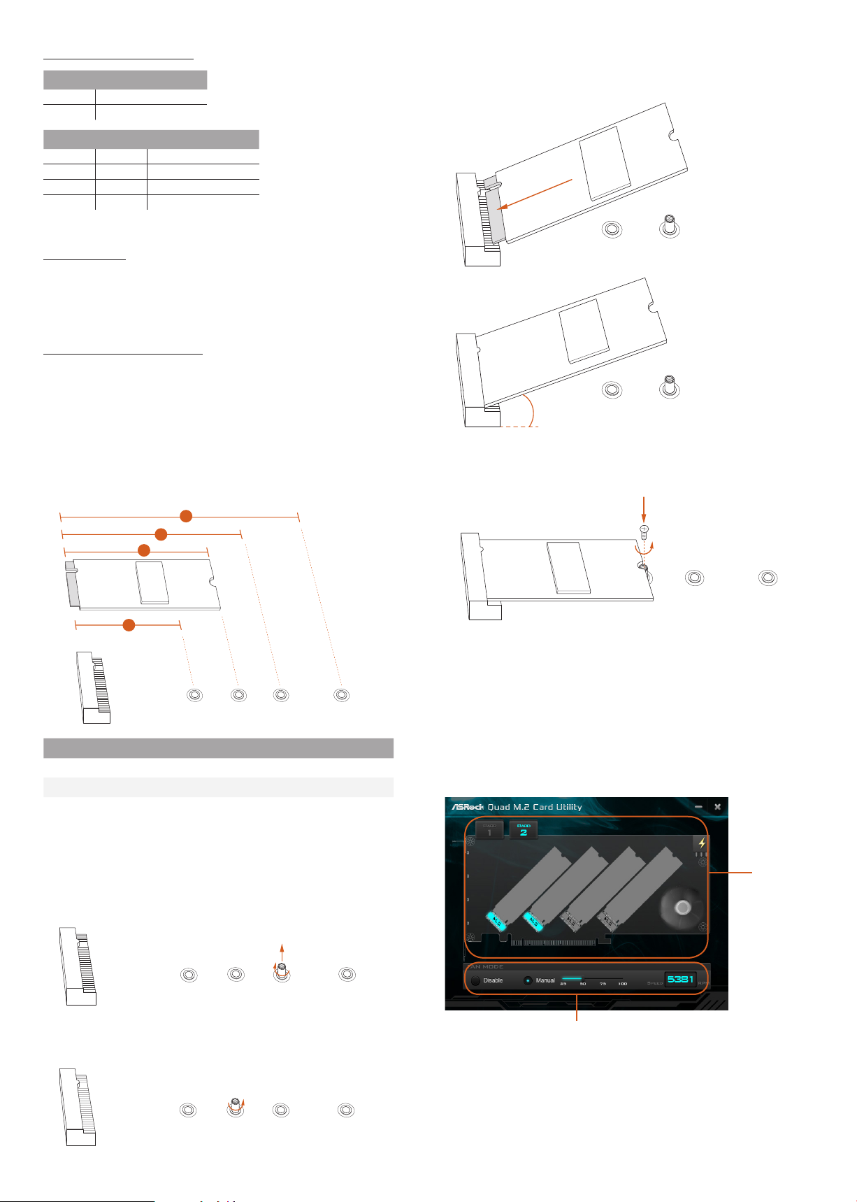
4. Gently insert the M.2 SSD module into the M.2 slot.
Please be aware that the M.2 SSD module only ts in one orientation.
o
20
A B
Installing M.2 SSD Module
1. Depending on the PCB type and length of your M.2 _SSD (NGFF) module,
nd the corresponding nut location to be used.
3
2
1
A
BC D
No. 1 2 3 4
Nut Location A B C D
PCB Length 4.2cm 6cm 8cm 11cm
Module Type Type 2242 Ty p e 2 2 6 0 Ty pe 2 280 Ty pe 2 2110
2. Move the stando based on the module ty pe and length. e stando is
placed at the nut location C by default. Skip Step 3 and 4 and go straight to
Step 5 if you are going to use the default nut. Otherwise, release the stando
by hand.
5. Tighten the screw with a screwdriver to secure the module into place.
Please do not overtighten the screw as this might damage the module.
NUT1NUT2
HYPER QUAD M.2 CARD Utility
With the ASRock HYPER QUAD M.2 CARD Utilit y, you can check that if your
M.2 SSD is properly installed and adjust the fan speed. Place the Support CD
into your DVD-ROM drive to run this utility or download it from the ASRock
website.
M.2 SSD
Status
A
3. Peel o the yellow protective lm on the nut to be used. Hand tighten the
BC D
stando into the desired nut location on the motherboard.
A
BC D
Select a fan speed mode
[Manual] Select a fan speed preference
[Disable] Turn o the fan
Page 3

Supported ASRock Motherboard Models:
Motherboard Models PCIE slots PCIe Slots* Utility Support
AMD TRX40 Chipset
TR X40 Taich i PCIE1, PCIE3, PCIE4
(PCIE4 is recommended)
TRX40 Creator
X299 Creator PCIE1 PCIE3 Yes (PCIE1, PCIE3)
X299 Taichi CLX PCIE1 PCIE3 Yes (PCIE1, PCIE3)
X299 Steel Legend PCIE1 PCIE3 Yes (PCIE1, PCIE3)
X299 OC Formula PCIE1 PCIE5 N/A
X299 Taichi XE PCIE1 PCIE3 Yes
X29 9 Taic hi PCIE1 PCIE3 N/A
Fatal1ty X299 Professional Gaming i9 XE PCIE1 PCIE3 Ye s
Fatal1ty X299 Professional Gaming i9 PCIE1 PCIE3 N/A
Fatal1ty X299 Gaming K6 PCIE1 PCIE3 N/A
X299 Extreme4 PCIE2 PCIE3 Ye s
X299M Extreme4 PCIE1 PCIE2 Yes
X299 Killer SLI/ac PCIE1 PCIE3 N/A
X399 Ta ich i PCIE4 N/A N/A
Fatal1ty X399 Professional Gaming PCIE4 N/A N/A
X399M Ta ich i PCIE2 N/A N/A
PCIE1, PCIE3
Support 4 M.2 modules
Intel X299 Chipset
AMD X399 Chipset
N/A
N/A Yes
Yes (PCIE1, PCIE3, PCIE4)
*e second PCIe Slot is only supported with CPU with 48 & 44 lanes.
*For the M.2 SSD support list and the updated information on the supported motherboard models, please visit ww w.asrock.com.
*Please note that the INTEL H10 series 512GB (HBRPEKNX0202A) (Gen3 x2) is not supported.
 Loading...