

Page 1
Copyright Notice:
No part of this installation guide may be reproduced, transcribed, transmitted, or translated in any language, in any form or by any means, except duplication of documentation
by the purchaser for backup purpose, without written consent of ASRock Inc.
Products and corporate names appearing in this guide may or may not be registered
trademarks or copyrights of their respective companies, and are used only for identifi ca-
tion or explanation and to the owners’ benefi t, without intent to infringe.
Disclaimer:
Specifi cations and information contained in this guide are furnished for informational use
only and subject to change without notice, and should not be constructed as a commitment by ASRock. ASRock assumes no responsibility for any errors or omissions that may
appear in this guide.
With respect to the contents of this guide, ASRock does not provide warranty of any kind,
either expressed or implied, including but not limited to the implied warranties or conditions of merchantability or fi tness for a particular purpose. In no event shall ASRock, its
directors, offi cers, employees, or agents be liable for any indirect, special, incidental, or
consequential damages (including damages for loss of profi ts, loss of business, loss of
data, interruption of business and the like), even if ASRock has been advised of the possibility of such damages arising from any defect or error in the guide or product.
This device complies with Part 15 of the FCC Rules. Operation is subject to the following
two conditions:
(1) this device may not cause harmful interference, and
(2) this device must accept any interference received, including interference that
may cause undesired operation.
CALIFORNIA, USA ONLY
The Lithium battery adopted on this motherboard contains Perchlorate, a toxic substance
controlled in Perchlorate Best Management Practices (BMP) regulations passed by the
California Legislature. When you discard the Lithium battery in California, USA, please
follow the related regulations in advance.
“Perchlorate Material-special handling may apply, see
www.dtsc.ca.gov/hazardouswaste/perchlorate”
ASRock Website: http://www.asrock.com
Published August 2011
Copyright©2011 ASRock INC. All rights reserved.
ASRock 970 Extreme3 Motherboard
English
1
Page 2
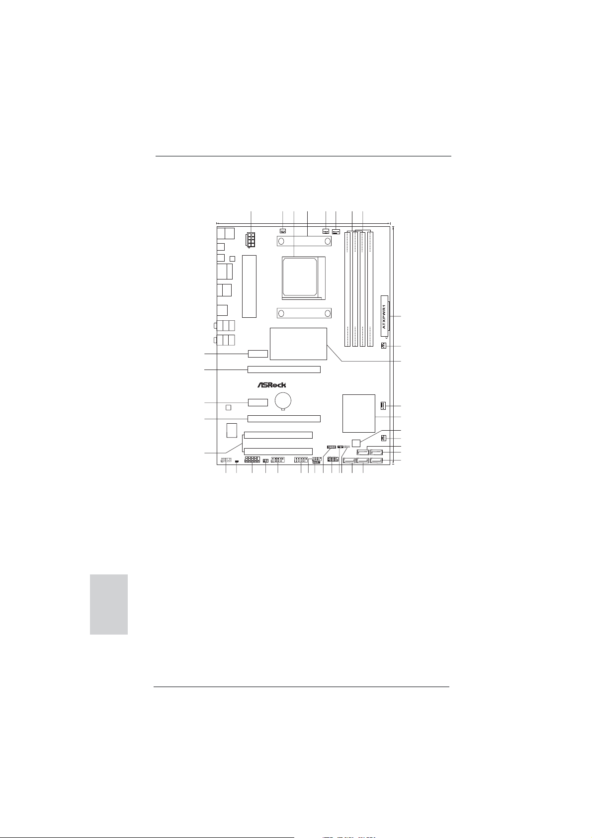
Motherboard Layout
1
Keyboard
Mouse
PS2
PS2
Coaxial
SPDIF
ATX12V1
Optical
SPDIF
LAN
PHY
RJ-45LAN
USB2.0
T:USB0
B:USB1
eSATA3
USB2.0
T:USB2
B:USB3
USB3.0
T:USB0
B:USB1
Top:
SIDE SPK
Bottom:
CTR BASS
Center:
REAR SPK
Bottom:
MIC IN
Top:
LINE IN
Center:
FRONT
USB 3.0
37
36
35
AUDIO
CODEC
34
Super
I/O
ErP/EuPReady
Designedin Taipei
33
1
COM1
HD_AUDIO1
HDMI_SPDIF1
1
1
31
32
30
21.8cm (8.6-in)
PCIE1
PCIE3
970 Extreme3
IR1
1
29
PCI1
PCI2
USB_8_9
1
28
2
CHA_FAN3
Chipset
PCIE2
CMOS
BATTERY
PCIE4
AMD
3
970
X
RoHS
1
5
4
CPU_FAN2
SOCKET AM3b
8
6
7
CPU_FAN1
Support 8-CoreCPU
FSB800
FSB800
DDR3 2100+
140W CPU
DDR3_A1(64 bit, 240-pinmodule)
DDR3_A2(64 bit, 240-pinmodule)
DDR3_B1(64 bit, 240-pinmodule)
DDR3_B2(64 bit, 240-pinmodule)
30.5cm (12.0-in)
9
AM3+
10
PWR_FAN1
11
FastLAN
AMD
SB950
Chipset
12
CHA_FAN1
13
14
X
FastUSB
32Mb
SATA36Gb/s
CLRCMOS1
BIOS
SPEAKER1
PLED1
1
1
1
PANEL1
PLEDPWRBTN
USB_4_5
USB_6_7
1
1
HDLED RESET
1
CIR1
27
25
23
26
24
SATA3_3
SATA3_4SATA3_5
1920
21
22
15
CHA_FAN2
16
SATA3_1
17
SATA3_2
18
English
1 ATX 12V Power Connector (ATX12V1) 20 SATA3 Connector (SATA3_5, Gray)
2 Chassis Fan Connector (CHA_FAN3) 21 Clear CMOS Jumper (CLRCMOS1)
3 AM3+ CPU Socket 22 Power LED Header (PLED1)
4 CPU Heatsink Retention Module 23 System Panel Header (PANEL1, Black)
5 CPU Fan Connector (CPU_FAN2) 24 Chassis Speaker Header (SPEAKER 1, Black)
6 CPU Fan Connector (CPU_FAN1) 25 Consumer Infrared Module Header
7 2 x 240-pin DDR3 DIMM Slots (CIR1)
(Dual Channel: DDR3_A1, DDR3_B1; Black) 26 USB 2.0 Header (USB_4_5, Black)
8 2 x 240-pin DDR3 DIMM Slots 27 USB 2.0 Header (USB_6_7, Black)
(Dual Channel: DDR3_A2, DDR3_B2; Black) 28 USB 2.0 Header (USB_8_9, Black)
9 ATX Power Connector (ATXPWR1) 29 Infrared Module Header (IR1)
10 Power Fan Connector (PWR_FAN1) 30 COM Port Header (COM1)
11 Northbridge Controller 31 HDMI_SPDIF Header
12 Chassis Fan Connector (CHA_FAN1) (HDMI_SPDIF1, Black)
13 Southbridge Controller 32 Front Panel Audio Header
14 SPI Flash Memory (32Mb) (HD_AUDIO1, Black)
15 Chassis Fan Connector (CHA_FAN2) 33 PCI Slots (PCI1-2)
16 SATA3 Connector (SATA3_3, Gray) 34 PCI Express 2.0 x16 Slot (PCIE4; Black)
17 SATA3 Connector (SATA3_1, Gray) 35 PCI Express 2.0 x1 Slot (PCIE3; Black)
18 SATA3 Connector (SATA3_2, Gray) 36 PCI Express 2.0 x16 Slot (PCIE2; Black)
19 SATA3 Connector (SATA3_4, Gray) 37 PCI Express 2.0 x1 Slot (PCIE1; Black)
2
ASRock 970 Extreme3 Motherboard
Page 3
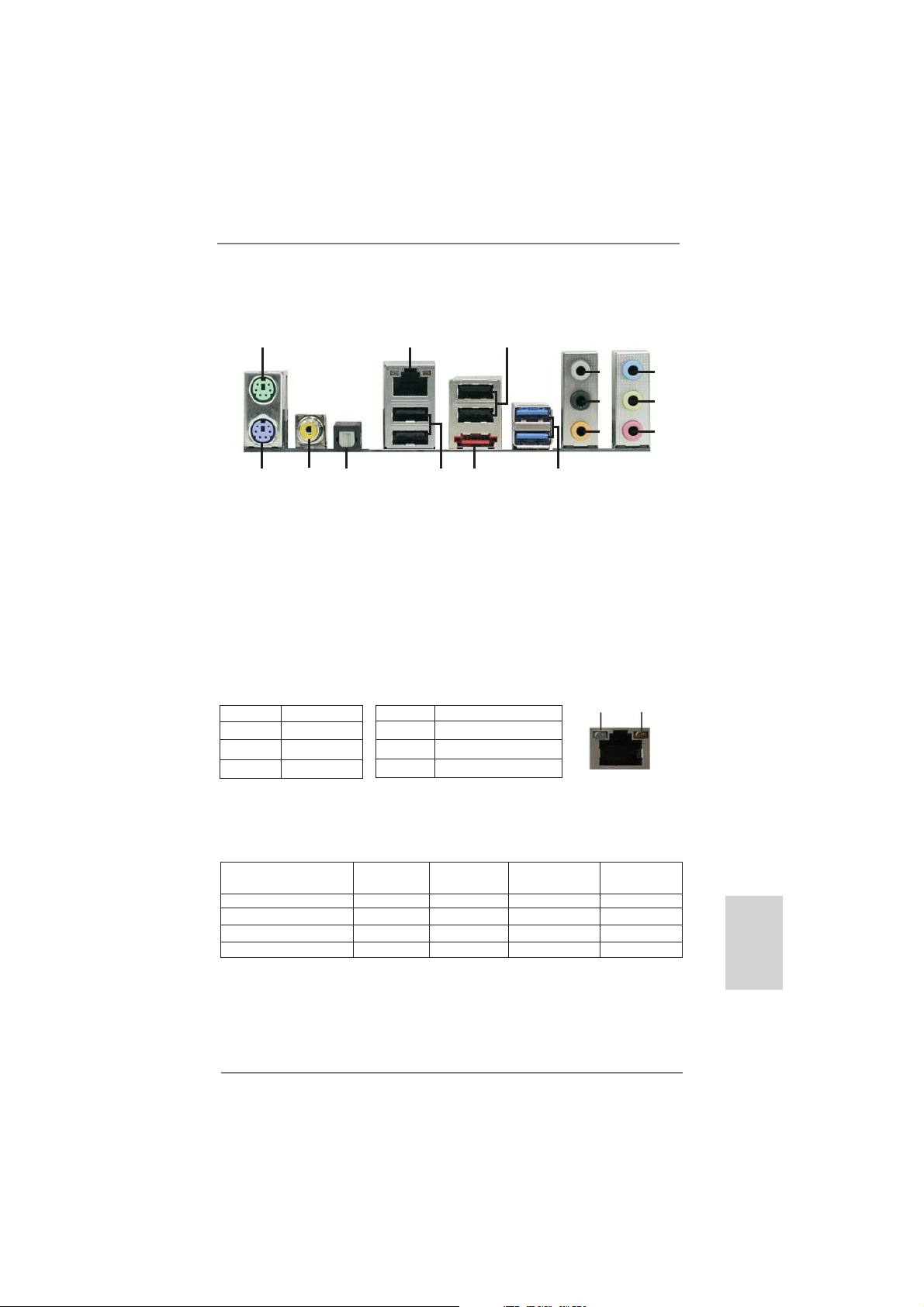
I/O Panel
11
3
4
5
6
7
8
9
10
ACT/LINK
LED
SPEED
LED
1
15
1 PS/2 Mouse Port (Green) 9 Microphone (Pink)
* 2 LAN RJ-45 Port 10 USB 3.0 Port (USB01)
3 USB 2.0 Ports (USB23) *** 11 eSATA3 Connector
4 Side Speaker (Gray) 12 USB 2.0 Ports (USB01)
5 Rear Speaker (Black) 13 Optical SPDIF Out Port
6 Central / Bass (Orange) 14 Coaxial SPDIF Out Port
7 Line In (Light Blue) 15 PS/2 Keyboard Port (Purple)
** 8 Front Speaker (Lime)
* There are two LED next to the LAN port. Please refer to the table below for the LAN port LED
indications.
Activity/Link LED SPEED LED
Status Description Status Description
14
13
LAN Port LED Indications
2
12
Off No Link Off 10Mbps connection
Blinking Data Activity Orange 100Mbps connection
On Link Green 1Gbps connection
LAN Port
If you use 2-channel speaker, please connect the speaker’s plug into “Front Speaker Jack”.
**
See the table below for connection details in accordance with the type of speaker you use.
TABLE for Audio Output Connection
Audio Output Channels Front Speaker Rear Speaker Central / Bass Side Speaker
(No. 8) (No. 5) (No. 6) (No. 4)
2 V -- -- -4 V V -- -6 V V V -8 V V V V
ASRock 970 Extreme3 Motherboard
English
3
Page 4

To enable Multi-Streaming function, you need to connect a front panel audio cable to the front
panel audio header. After restarting your computer, you will fi nd “Mixer” tool on your system.
Please select “Mixer ToolBox” , click “Enable playback multi-streaming”, and click “ok”.
Choose “2CH”, “4CH”, “6CH”, or “8CH” and then you are allowed to select “Realtek HDA Primary output” to use Rear Speaker, Central/Bass, and Front Speaker, or select “Realtek HDA
Audio 2nd output” to use front panel audio.
*** eSATA3 connector supports SATA Gen3 in cable 1M.
English
4
ASRock 970 Extreme3 Motherboard
Page 5
1. Introduction
Thank you for purchasing ASRock 970 Extreme3 motherboard, a reliable motherboard produced under ASRock’s consistently stringent quality control. It delivers
excellent performance with robust design conforming to ASRock’s commitment to
quality and endurance.
This Quick Installation Guide contains introduction of the motherboard and step-bystep installation guide. More detailed information of the motherboard can be found
in the user manual presented in the Support CD.
Because the motherboard specifi cations and the BIOS software might
be updated, the content of this manual will be subject to change without
notice. In case any modifi cations of this manual occur, the updated ver-
sion will be available on ASRock website without further notice. You may
fi nd the latest VGA cards and CPU support lists on ASRock website as
well. ASRock website http://www.asrock.com
If you require technical support related to this motherboard, please visit
our website for specifi c information about the model you are using.
www.asrock.com/support/index.asp
1.1 Package Contents
ASRock 970 Extreme3 Motherboard
(ATX Form Factor: 12.0-in x 8.6-in, 30.5 cm x 21.8 cm)
ASRock 970 Extreme3 Quick Installation Guide
ASRock 970 Extreme3 Support CD
2 x Serial ATA (SATA) Data Cables (Optional)
1 x I/O Panel Shield
ASRock Reminds You...
To get better performance in Windows® 7 / 7 64-bit / VistaTM / VistaTM 64
bit, it is recommended to set the BIOS option in Storage Confi guration
to AHCI mode. For the BIOS setup, please refer to the “User Manual” in
our support CD for details.
ASRock 970 Extreme3 Motherboard
English
5
Page 6

English
1.2 Specifications
Platform - ATX Form Factor: 12.0-in x 8.6-in, 30.5 cm x 21.8 cm
- All Solid Capacitor design (100% Japan-made high-quality
Conductive Polymer Capacitors)
CPU - Support for Socket AM3+ processors
- Support for Socket AM3 processors: AMD Phenom
X4 / X3 / X2 (except 920 / 940) / Athlon II X4 / X3 / X2 /
Sempron processors
- Supports 8-Core CPU
- Supports UCC feature (Unlock CPU Core) (see CAUTION 1)
- V4 + 1 Power Phase Design
- Supports CPU up to 140W
- Supports AMD’s Cool ‘n’ Quiet
TM
Technology
- FSB 2400 MHz (4.8 GT/s)
- Supports Untied Overclocking Technology (see CAUTION 2)
- Supports Hyper-Transport 3.0 (HT 3.0) Technology
Chipset - Northbridge: AMD 970
- Southbridge: AMD SB950
Memory - Dual Channel DDR3 Memory Technology (see CAUTION 3)
- 4 x DDR3 DIMM slots
- Support DDR3 2100(OC)/1866(OC)/1800(OC)/1600(OC)/
1333/1066/800 non-ECC, un-buffered memory
(see CAUTION 4)
- Max. capacity of system memory: 32GB (see CAUTION 5)
Expansion Slot - 2 x PCI Express 2.0 x16 slots
(PCIE2 @ x16 mode; PCIE4 @ x4 mode)
- 2 x PCI Express 2.0 x1 slots
- 2 x PCI slots
- Supports AMD
TM
Quad CrossFireXTM and CrossFireX
Audio - 7.1 CH HD Audio with Content Protection
(Realtek ALC892 Audio Codec)
- Premium Blu-ray audio support
- Supports THX TruStudio
TM
LAN - PCIE x1 Gigabit LAN 10/100/1000 Mb/s
- Realtek RTL8111E
- Supports Wake-On-LAN
- Supports LAN Cable Detection
- Supports Energy Effi cient Ethernet 802.3az
- Supports PXE
TM
II X6 /
TM
6
ASRock 970 Extreme3 Motherboard
Page 7
Rear Panel I/O I/O Panel
- 1 x PS/2 Mouse Port
- 1 x PS/2 Keyboard Port
- 1 x Coaxial SPDIF Out Port
- 1 x Optical SPDIF Out Port
- 4 x Ready-to-Use USB 2.0 Ports
- 2 x Ready-to-Use USB 3.0 Ports
- 1 x eSATA3 Connector
- 1 x RJ-45 LAN Port with LED (ACT/LINK LED and SPEED
LED)
- HD Audio Jack: Side Speaker/Rear Speaker/Central/Bass/
Line in/Front Speaker/Microphone (see CAUTION 6)
SATA 3 - 5 x SATA3 6.0 Gb/s connectors, support RAID (RAID 0,
RAID 1, RAID 5 and RAID 10), NCQ, AHCI and "Hot Plug"
functions
USB 3.0 - 2 x USB 3.0 ports by Etron EJ168A, support USB 1.0/2.0/3.0
up to 5Gb/s
Connector - 5 x SATA3 6.0Gb/s connectors
- 1 x IR header
- 1 x CIR header
- 1 x COM port header
- 1 x HDMI_SPDIF header
- 1 x Power LED header
- CPU/Chassis/Power FAN connector
- 24 pin ATX power connector
- 8 pin 12V power connector
- Front panel audio connector
- 3 x USB 2.0 headers (support 6 USB 2.0 ports)
BIOS Feature - 32Mb AMI UEFI Legal BIOS with GUI support
- Supports “Plug and Play”
- ACPI 1.1 Compliance Wake Up Events
- Supports jumperfree
- SMBIOS 2.3.1 Support
- CPU, VCCM, NB, SB Voltage Multi-adjustment
Support CD - Drivers, Utilities, AntiVirus Software (Trial Version),
CyberLink MediaEspresso 6.5 Trial, AMD OverDrive
TM
Utility,
AMD Fusion, AMD Fusion Media Explorer, ASRock Software
Suite (CyberLink DVD Suite - OEM and Trial; ASRock
MAGIX Multimedia Suite - OEM)
English
ASRock 970 Extreme3 Motherboard
7
Page 8
Unique Feature - ASRock Extreme Tuning Utility (AXTU) (see CAUTION 7)
- ASRock Instant Boot
- ASRock Instant Flash (see CAUTION 8)
- ASRock APP Charger (see CAUTION 9)
- ASRock SmartView (see CAUTION 10)
- ASRock XFast USB (see CAUTION 11)
- ASRock XFast LAN (see CAUTION 12)
- ASRock On/Off Play Technology (see CAUTION 13)
- Hybrid Booster:
- CPU Frequency Stepless Control (see CAUTION 14)
- ASRock U-COP (see CAUTION 15)
- Boot Failure Guard (B.F.G.)
- Turbo UCC
Hardware - CPU Temperature Sensing
Monitor - Chassis Temperature Sensing
- CPU/Chassis/Power Fan Tachometer
- CPU/Chassis Quiet Fan
- CPU/Chassis Fan Multi-Speed Control
- Voltage Monitoring: +12V, +5V, +3.3V, Vcore
OS - Microsoft
®
Windows® 7 / 7 64-bit / Vista
TM
/ VistaTM 64-bit / XP
/ XP 64-bit compliant
Certifi cations - FCC, CE, WHQL
- ErP/EuP Ready (ErP/EuP ready power supply is required)
(see CAUTION 16)
* For detailed product information, please visit our website: http://www.asrock.com
English
WARNING
Please realize that there is a certain risk involved with overclocking, including adjusting the
setting in the BIOS, applying Untied Overclocking Technology, or using the third-party overclocking tools. Overclocking may affect your system stability, or even cause damage to the
components and devices of your system. It should be done at your own risk and expense.
We are not responsible for possible damage caused by overclocking.
8
ASRock 970 Extreme3 Motherboard
Page 9

CAUTION!
1. ASRock UCC (Unlock CPU Core) feature simplifi es AMD CPU activa-
tion. As long as a simple switch of the UEFI option “ASRock UCC”, you
can unlock the extra CPU core to enjoy an instant performance boost.
When UCC feature is enabled, the dual-core or triple-core CPU will boost
to the quad-core CPU, and some CPU, including quad-core CPU, can
also increase L3 cache size up to 6MB, which means you can enjoy the
upgrade CPU performance with a better price. Please be noted that UCC
feature is supported with AM3/AM3+ CPU only, and in addition, not every
AM3/AM3+ CPU can support this function because some CPU’s hidden
core may be malfunctioned.
2. This motherboard supports Untied Overclocking Technology. Please read
“Untied Overclocking Technology” on page 27 for details.
3. This motherboard supports Dual Channel Memory Technology. Before
you implement Dual Channel Memory Technology, make sure to read the
installation guide of memory modules on page 14 for proper installation.
4. Whether 2100/1866/1800/1600MHz memory speed is supported depends on the AM3/AM3+ CPU you adopt. If you want to adopt DDR3
2100/1866/1800/1600 memory module on this motherboard, please refer
to the memory support list on our website for the compatible memory
modules. Non OC mode’s DDR3 1866 is supported by AM3+ CPU.
ASRock website: http://www.asrock.com
5. Due to the operating system limitation, the actual memory size may be
less than 4GB for the reservation for system usage under Windows
TM
Vista
/ XP. For Windows® 64-bit OS with 64-bit CPU, there is no such
limitation.
6. For microphone input, this motherboard supports both stereo and mono
modes. For audio output, this motherboard supports 2-channel, 4-channel, 6-channel, and 8-channel modes. Please check the table on page 3
for proper connection.
7. ASRock Extreme Tuning Utility (AXTU) is an all-in-one tool to ne-tune
different system functions in a user-friendly interface, which is including
Hardware Monitor, Fan Control, Overclocking, OC DNA and IES. In Hardware Monitor, it shows the major readings of your system. In Fan Control,
it shows the fan speed and temperature for you to adjust. In Overclocking, you are allowed to overclock CPU frequency for optimal system
performance. In OC DNA, you can save your OC settings as a profi le
and share with your friends. Your friends then can load the OC profi le to
their own system to get the same OC settings. In IES (Intelligent Energy
Saver), the voltage regulator can reduce the number of output phases to
improve effi ciency when the CPU cores are idle without sacrifi cing com-
puting performance. Please visit our website for the operation procedures
of ASRock Extreme Tuning Utility (AXTU).
ASRock website: http://www.asrock.com
®
7 /
English
ASRock 970 Extreme3 Motherboard
9
Page 10

English
8. ASRock Instant Flash is a BIOS fl ash utility embedded in Flash ROM.
This convenient BIOS update tool allows you to update system BIOS
without entering operating systems fi rst like MS-DOS or Windows®. With
this utility, you can press <F6> key during the POST or press <F2> key to
BIOS setup menu to access ASRock Instant Flash. Just launch this tool
and save the new BIOS fi le to your USB fl ash drive, fl oppy disk or hard
drive, then you can update your BIOS only in a few clicks without preparing an additional fl oppy diskette or other complicated fl ash utility. Please
be noted that the USB fl ash drive or hard drive must use FAT32/16/12 fi le
system.
9. If you desire a faster, less restricted way of charging your Apple devices,
such as iPhone/iPod/iPad Touch, ASRock has prepared a wonderful solution for you - ASRock APP Charger. Simply installing the APP Charger
driver, it makes your iPhone charged much quickly from your computer
and up to 40% faster than before. ASRock APP Charger allows you to
quickly charge many Apple devices simultaneously and even supports
continuous charging when your PC enters into Standby mode (S1), Suspend to RAM (S3), hibernation mode (S4) or power off (S5). With APP
Charger driver installed, you can easily enjoy the marvelous charging
experience than ever.
ASRock website: http://www.asrock.com/Feature/AppCharger/index.asp
10. ASRock SmartView, a new function of internet browser, is the smart start
page for IE that combines your most visited web sites, your history, your
Facebook friends and your real-time newsfeed into an enhanced view for
a more personal Internet experience. ASRock motherboards are exclusively equipped with the ASRock SmartView utility that helps you keep in
touch with friends on-the-go. To use ASRock SmartView feature, please
make sure your OS version is Windows
bit, and your browser version is IE8.
ASRock website: http://www.asrock.com/Feature/SmartView/index.asp
11. ASRock XFast USB can boost USB storage device performance. The
performance may depend on the property of the device.
12. ASRock XFast LAN provides a faster internet access, which includes be-
low benefi ts. LAN Application Prioritization: You can confi gure your appli-
cation priority ideally and/or add new programs. Lower Latency in Game:
After setting online game priority higher, it can lower the latency in game.
Traffic Shaping: You can watch Youtube HD video and download files
simultaneously. Real-Time Analysis of Your Data: With the status window,
you can easily recognize which data streams you are currently transferring.
13. ASRock On/Off Play Technology allows users to enjoy the great audio ex-
perience from the portable audio devices, such like MP3 player or mobile
phone to your PC, even when the PC is turned off (or in ACPI S5 mode)!
This motherboard also provides a free 3.5mm audio cable (optional) that
ensures users the most convenient computing environment.
®
7 / 7 64 bit / VistaTM / VistaTM 64
10
ASRock 970 Extreme3 Motherboard
Page 11

14. Although this motherboard offers stepless control, it is not recommended
to perform over-clocking. Frequencies other than the recommended CPU
bus frequencies may cause the instability of the system or damage the
CPU.
15. While CPU overheat is detected, the system will automatically shutdown.
Before you resume the system, please check if the CPU fan on the motherboard functions properly and unplug the power cord, then plug it back
again. To improve heat dissipation, remember to spray thermal grease
between the CPU and the heatsink when you install the PC system.
16. EuP, stands for Energy Using Product, was a provision regulated by European Union to defi ne the power consumption for the completed system.
According to EuP, the total AC power of the completed system shall be
under 1.00W in off mode condition. To meet EuP standard, an EuP ready
motherboard and an EuP ready power supply are required. According to
Intel’s suggestion, the EuP ready power supply must meet the standard
of 5v standby power effi ciency is higher than 50% under 100 mA current
consumption. For EuP ready power supply selection, we recommend you
checking with the power supply manufacturer for more details.
ASRock 970 Extreme3 Motherboard
English
11
Page 12

2. Installation
This is an ATX form factor (12.0-in x 8.6-in, 30.5 cm x 21.8 cm) motherboard.
Before you install the motherboard, study the confi guration of your chassis to ensure
that the motherboard fi ts into it.
Pre-installation Precautions
Take note of the following precautions before you install motherboard
components or change any motherboard settings.
Before you install or remove any component, ensure that the
power is switched off or the power cord is detached from the
power supply. Failure to do so may cause severe damage to the
motherboard, peripherals, and/or components.
1. Unplug the power cord from the wall socket before touching any
component.
2. To avoid damaging the motherboard components due to static electricity, NEVER place your motherboard directly on the carpet or the
like. Also remember to use a grounded wrist strap or touch a safety
grounded object before you handle components.
3. Hold components by the edges and do not touch the ICs.
4. Whenever you uninstall any component, place it on a grounded antistatic pad or in the bag that comes with the component.
5. When placing screws into the screw holes to secure the motherboard to the chassis, please do not over-tighten the screws! Doing
so may damage the motherboard.
English
12
ASRock 970 Extreme3 Motherboard
Page 13
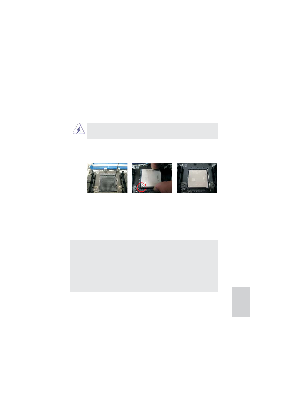
2.1 CPU Installation
Step 1. Unlock the socket by lifting the lever up to a 90
o
angle.
Step 2. Position the CPU directly above the socket such that the CPU corner with
the golden triangle matches the socket corner with a small triangle.
Step 3. Carefully insert the CPU into the socket until it fi ts in place.
The CPU fi ts only in one correct orientation. DO NOT force the CPU
into the socket to avoid bending of the pins.
Step 4. When the CPU is in place, press it fi rmly on the socket while you push
down the socket lever to secure the CPU. The lever clicks on the side tab
to indicate that it is locked.
Lever 90° Up
CPU Golden Triangle
STEP 1:
Lift Up The Socket Lever
STEP 2 / STEP 3:
Match The CPU Golden Triangle
To The Socket Corner Small
Triangle
Socker Corner
Small Triangle
STEP 4:
Push Down And Lock
The Socket Lever
2.2 Installation of CPU Fan and Heatsink
After you install the CPU into this motherboard, it is necessary to install a
larger heatsink and cooling fan to dissipate heat. You also need to spray
thermal grease between the CPU and the heatsink to improve heat dissipation. Make sure that the CPU and the heatsink are securely fastened
and in good contact with each other. Then connect the CPU fan to the
CPU FAN connector (CPU_FAN1, see Page 2, No. 6 or CPU_FAN2, see
Page 2, No. 5). For proper installation, please kindly refer to the instruction manuals of the CPU fan and the heatsink.
ASRock 970 Extreme3 Motherboard
English
13
Page 14
English
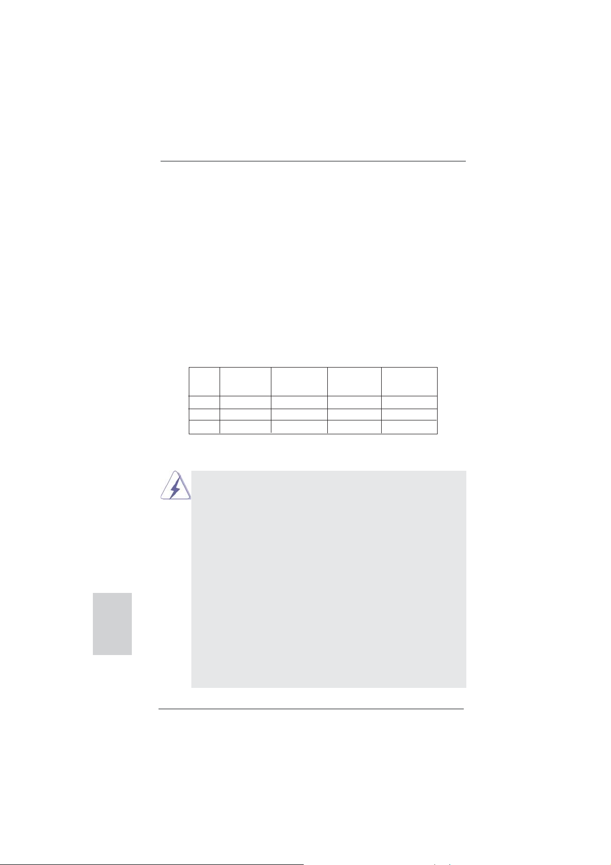
2.3 Installation of Memory Modules (DIMM)
This motherboard provides four 240-pin DDR3 (Double Data Rate 3) DIMM slots,
and supports Dual Channel Memory Technology. For dual channel confi guration,
you always need to install identical (the same brand, speed, size and chip-type)
DDR3 DIMM pair in the slots. In other words, you have to install identical DDR3
DIMM pair in Dual Channel (DDR3_A1 and DDR3_B1; Black slots; see p.2 No.7)
or identical DDR3 DIMM pair in Dual Channel (DDR3_A2 and DDR3_B2; Black
slots; see p.2 No.8), so that Dual Channel Memory Technology can be activated.
This motherboard also allows you to install four DDR3 DIMMs for dual channel
confi guration, and please install identical DDR3 DIMMs in all four slots. You may
refer to the Dual Channel Memory Confi guration Table below.
Dual Channel Memory Confi gurations
DDR3_A1 DDR3_A2 DDR3_B1 DDR3_B2
(Black Slot) (Black Slot) (Black Slot) (Black Slot)
(1) Populated - Populated (2) - Populated - Populated
(3)* Populated Populated Populated Populated
For the confi guration (3), please install identical DDR3 DIMMs in all four
*
slots.
1. Please install the memory module into the slots DDR3_A2 and
DDR3_B2 for the fi rst priority.
2. If you want to install two memory modules, for optimal compatibility
and reliability, it is recommended to install them either in the set of
slots DDR3_A1 and DDR3_B1, or in the set of slots DDR3_A2 and
DDR3_B2.
3. If only one memory module or three memory modules are installed
in the DDR3 DIMM slots on this motherboard, it is unable to activate
the Dual Channel Memory Technology.
4. If a pair of memory modules is NOT installed in the same Dual
Channel, for example, installing a pair of memory modules in
DDR3_A1 and DDR3_A2, it is unable to activate the Dual Channel
Memory Technology .
5. It is not allowed to install a DDR or DDR2 memory module into
DDR3 slot; otherwise, this motherboard and DIMM may be damaged.
6. If you adopt DDR3 2100/1866/1800/1600 memory modules on this
motherboard, it is recommended to install them on DDR3_A2 and
DDR3_B2 slots.
14
ASRock 970 Extreme3 Motherboard
Page 15
Installing a DIMM
Please make sure to disconnect power supply before adding or
removing DIMMs or the system components.
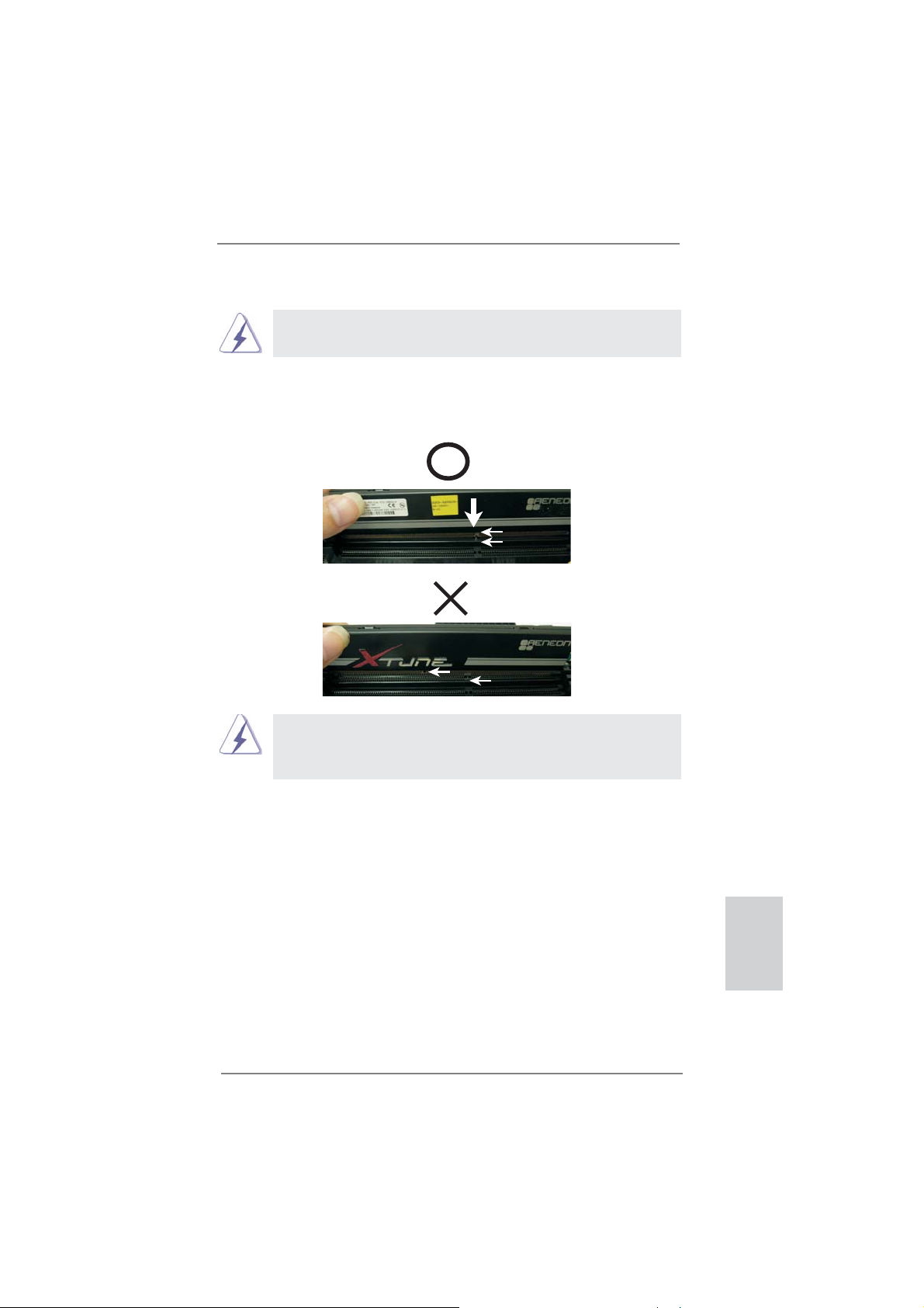
Step 1. Unlock a DIMM slot by pressing the retaining clips outward.
Step 2. Align a DIMM on the slot such that the notch on the DIMM matches the
break on the slot.
notch
break
notch
break
The DIMM only fi ts in one correct orientation. It will cause permanent
damage to the motherboard and the DIMM if you force the DIMM into
the slot at incorrect orientation.
Step 3. Firmly insert the DIMM into the slot until the retaining clips at both ends
fully snap back in place and the DIMM is properly seated.
ASRock 970 Extreme3 Motherboard
English
15
Page 16

2.4 Expansion Slots (PCI and PCI Express Slots)
There are 2 PCI slots and 4 PCI Express slots on this motherboard.
PCI Slots: PCI slots are used to install expansion cards that have the 32-bit PCI
interface.
PCIE Slots:
PCIE1 / PCIE3 (PCIE x1 slot; Black) is used for PCI Express cards with
x1 lane width cards, such as Gigabit LAN card and SATA2 card.
PCIE2 (PCIE x16 slot; Black) is used for PCI Express x16 lane width
graphics cards, or used to install PCI Express graphics cards to support
CrossFireX
PCIE4 (PCIE x16 slot; Black) is used for PCI Express x4 lane width
cards, or used to install PCI Express graphics cards to support
CrossFireX
1. In single VGA card mode, it is recommended to install a PCI Ex-
2. In CrossFireXTM mode, please install PCI Express x16 graphics
3. Please connect a chassis fan to motherboard chassis fan connec-
TM
function.
TM
function.
press x16 graphics card on PCIE2 slot.
cards on PCIE2 and PCIE4 slots. Therefore, PCIE2 slot will work at
x16 bandwidth while PCIE4 slot will work at x4 bandwidth.
tor (CHA_FAN1, CHA_FAN2 or CHA_FAN3) when using multiple
graphics cards for better thermal environment.
English
Installing an expansion card
Step 1. Before installing the expansion card, please make sure that the power
supply is switched off or the power cord is unplugged. Please read the
documentation of the expansion card and make necessary hardware
settings for the card before you start the installation.
Step 2. Remove the system unit cover (if your motherboard is already installed
in a chassis).
Step 3. Remove the bracket facing the slot that you intend to use. Keep the
screws for later use.
Step 4. Align the card connector with the slot and press fi rmly until the card is
completely seated on the slot.
Step 5. Fasten the card to the chassis with screws.
Step 6. Replace the system cover.
16
ASRock 970 Extreme3 Motherboard
Page 17
2.5 CrossFireXTM and Quad CrossFireX
This motherboard supports CrossFireX
TM
Operation Guide
TM
and Quad CrossFireXTM feature.
CrossFireXTM technology offers the most advantageous means available of
combining multiple high performance Graphics Processing Units (GPU) in a single
PC. Combining a range of different operating modes with intelligent software design
TM
and an innovative interconnect mechanism, CrossFireX
enables the highest
possible level of performance and image quality in any 3D application. Currently
CrossFireXTM feature is supported with Windows® XP with Service Pack 2 / VistaTM /
7 OS. Quad CrossFireX
TM
feature are supported with Windows® VistaTM / 7 OS only.
Please check AMD website for AMDTM CrossFireXTM driver updates.
1. If a customer incorrectly configures their system they will not see the
performance benefi ts of CrossFireXTM. All three CrossFireXTM components, a
CrossFireX
CrossFireXTM Edition co-processor graphics card, must be installed correctly
to benefi t from the CrossFireXTM multi-GPU platform.
2. If you pair a 12-pipe CrossFireXTM Edition card with a 16-pipe card, both
cards will operate as 12-pipe cards while in CrossFireXTM mode.
TM
Ready graphics card, a CrossFireXTM Ready motherboard and a
2.5.1 Graphics Card Setup
2.5.1.1 Installing Two CrossFireXTM-Ready Graphics
Cards
Different CrossFireXTM cards may require different methods to enable CrossFi-
reXTM feature. In the following procedures, we use Radeon HD 3870 as the example graphics card. For other CrossFireXTM cards that AMDTM has released or will
release in the future, please refer to AMD
installation guide.
TM
graphics card manuals for detailed
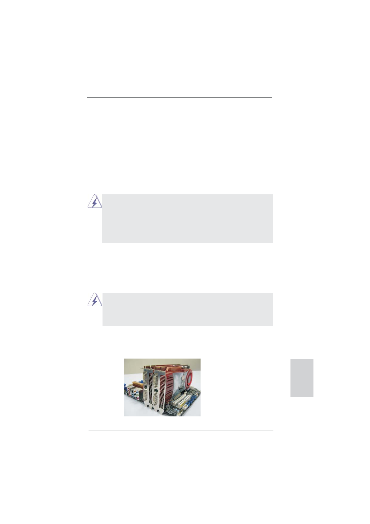
Step 1. Insert one Radeon graphics card into PCIE2 slot and the other Radeon
graphics card to PCIE4 slot. Make sure that the cards are properly seated
on the slots.
ASRock 970 Extreme3 Motherboard
English
17
Page 18
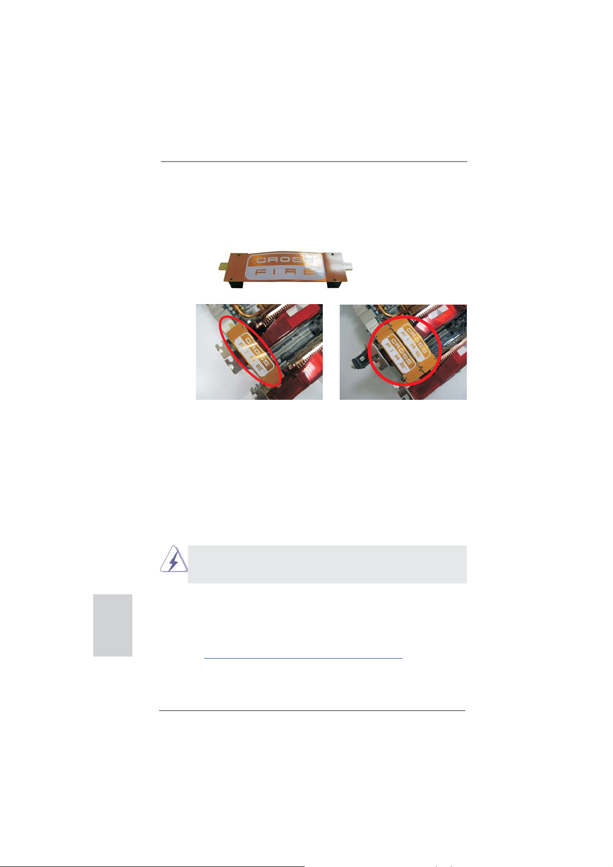
Step 2. Connect two Radeon graphics cards by installing CrossFire Bridge on
CrossFire Bridge Interconnects on the top of Radeon graphics cards.
(CrossFire Bridge is provided with the graphics card you purchase, not
bundled with this motherboard. Please refer to your graphics card vendor
for details.)
CrossFire Bridge
or
Step 3. Connect the DVI monitor cable to the DVI connector on the Radeon graph-
ics card on PCIE2 slot. (You may use the DVI to D-Sub adapter to convert
the DVI connector to D-Sub interface, and then connect the D-Sub monitor
cable to the DVI to D-Sub adapter.)
English
2.5.2 Driver Installation and Setup
Step 1. Power on your computer and boot into OS.
Step 2. Remove the AMD
tem.
The Catalyst Uninstaller is an optional download. We recommend using this
utility to uninstall any previously installed Catalyst drivers prior to installation.
Please check AMD website for AMD
Step 3. Install the required drivers to your system.
For Windows® XP OS:
A. AMD
TM
installed (If you have Windows® XP Service Pack 2 or higher installed
in your system, there is no need to download it again):
http://www.microsoft.com/windowsxp/sp2/default.mspx
B. You must have Microsoft .NET Framework installed prior to
downloading and installing the CATALYST Control Center. Please
check Microsoft website for details.
18
TM
driver if you have any VGA driver installed in your sys-
TM
driver updates.
recommends Windows® XP Service Pack 2 or higher to be
ASRock 970 Extreme3 Motherboard
Page 19
For Windows® 7 / VistaTM OS:
Install the CATALYST Control Center. Please check AMD website for de-
tails.
Step 4. Restart your computer.
Step 5. Install the VGA card drivers to your system, and restart your computer.
®
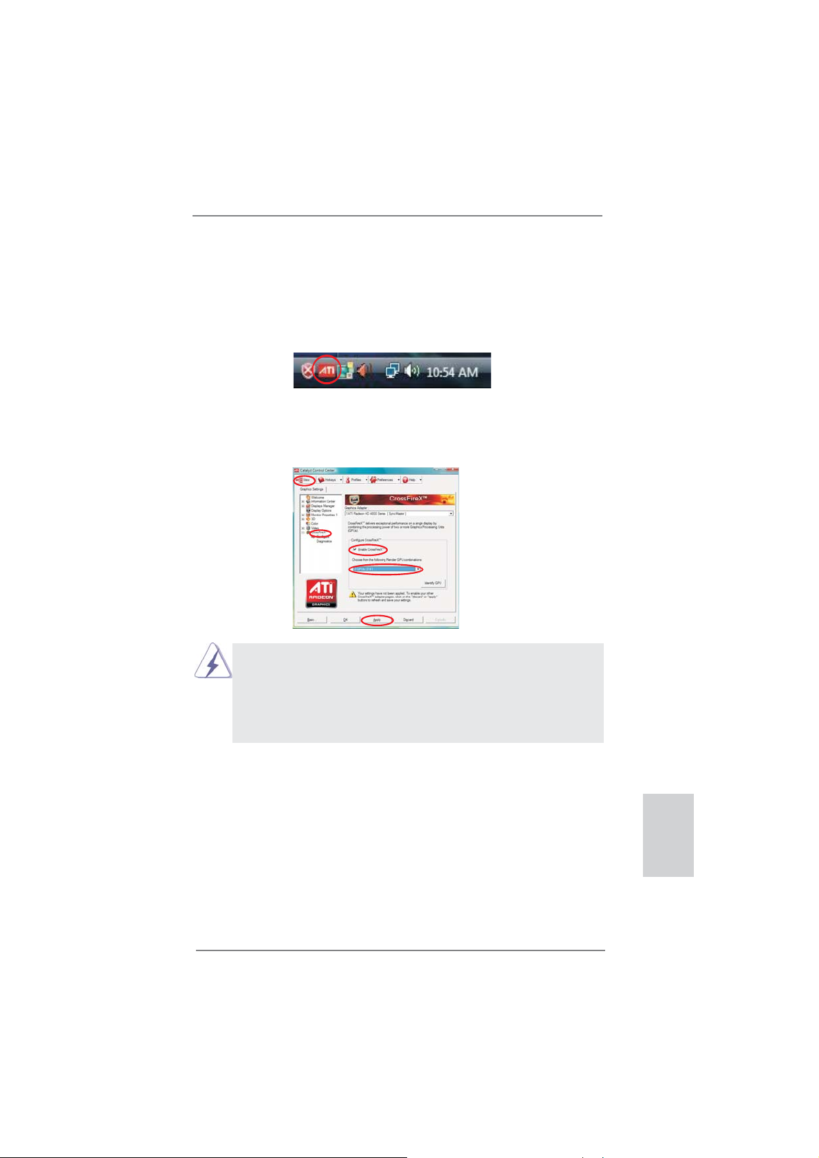
Then you will fi nd “ATI Catalyst Control Center” on your Windows
ATI Catalyst Control Center
taskbar.
Step 6. Double-click “ATI Catalyst Control Center”. Click “View”, select “CrossFi-
reXTM”, and then check the item “Enable CrossFireXTM”. Select “2 GPUs”
and click “Apply” (if you install two Radeon graphics cards).
Although you have selected the option “Enable CrossFireTM”, the Cross-
TM
FireX
function may not work actually. Your computer will automatically
reboot. After restarting your computer, please confi rm whether the option
“Enable CrossFireTM” in “ATI Catalyst Control Center” is selected or not;
if not, please select it again, and then you are able to enjoy the benefi t of
CrossFireX
TM
feature.
Step 7. You can freely enjoy the benefi t of CrossFireXTM or Quad CrossFireXTM
feature.
* CrossFireXTM appearing here is a registered trademark of AMDTM Technologies Inc., and is
used only for identifi cation or explanation and to the owners’ benefi t, without intent to infringe.
* For further information of AMD
updates and details.
TM
CrossFireXTM technology, please check AMD website for
ASRock 970 Extreme3 Motherboard
English
19
Page 20

2.6 Surround Display Feature
This motherboard supports Surround Display upgrade. With the external add-on PCI
Express VGA cards, you can easily enjoy the benefi ts of Surround Display feature.
For the detailed instruction, please refer to the document at the following path in the
Support CD:
..\ Surround Display Information
2.7 ASRock Smart Remote Installation Guide
ASRock Smart Remote is only used for ASRock motherboard with CIR header.
Please refer to below procedures for the quick installation and usage of ASRock
Smart Remote.
Step1. Find the CIR header located next
to the USB 2.0 header on ASRock
motherboard.
USB 2.0 header (9-pin, black)
CIR header (4-pin, gray)
English
Step2. Connect the front USB cable to the
USB 2.0 header (as below, pin 1-5)
and the CIR header. Please make
sure the wire assignments and the
pin assignments are matched
correctly.
Step3. Install Multi-Angle CIR Receiver to
the front USB port. If Multi-Angle
CIR Receiver
cannot successfully
receive the infrared signals from
MCE Remote Controller, please try
to install it to the other front USB
port.
3 CIR sensors in different angles
USB_PWR
1
ATX+5VSB
P-
2
IRRX
P+
3
IRTX
GND
GND
4
DUMMY
5
20
ASRock 970 Extreme3 Motherboard
Page 21
1. Only one of the front USB port can support CIR function. When
the CIR function is enabled, the other port will remain USB
function.
2. Multi-Angle CIR Receiver
not use the rear USB bracket to connect it on the rear panel.
Multi-Angle CIR Receiver can receive the multi-direction infrared
signals (top, down and front), which is compatible with most of
the chassis on the market.
3. The Multi-Angle CIR Receiver does not support Hot-Plug
function. Please install it before you boot the system.
* ASRock Smart Remote is only supported by some of ASRock motherboards. Please refer to
ASRock website for the motherboard support list: http://www.asrock.com
is used for front USB only. Please do
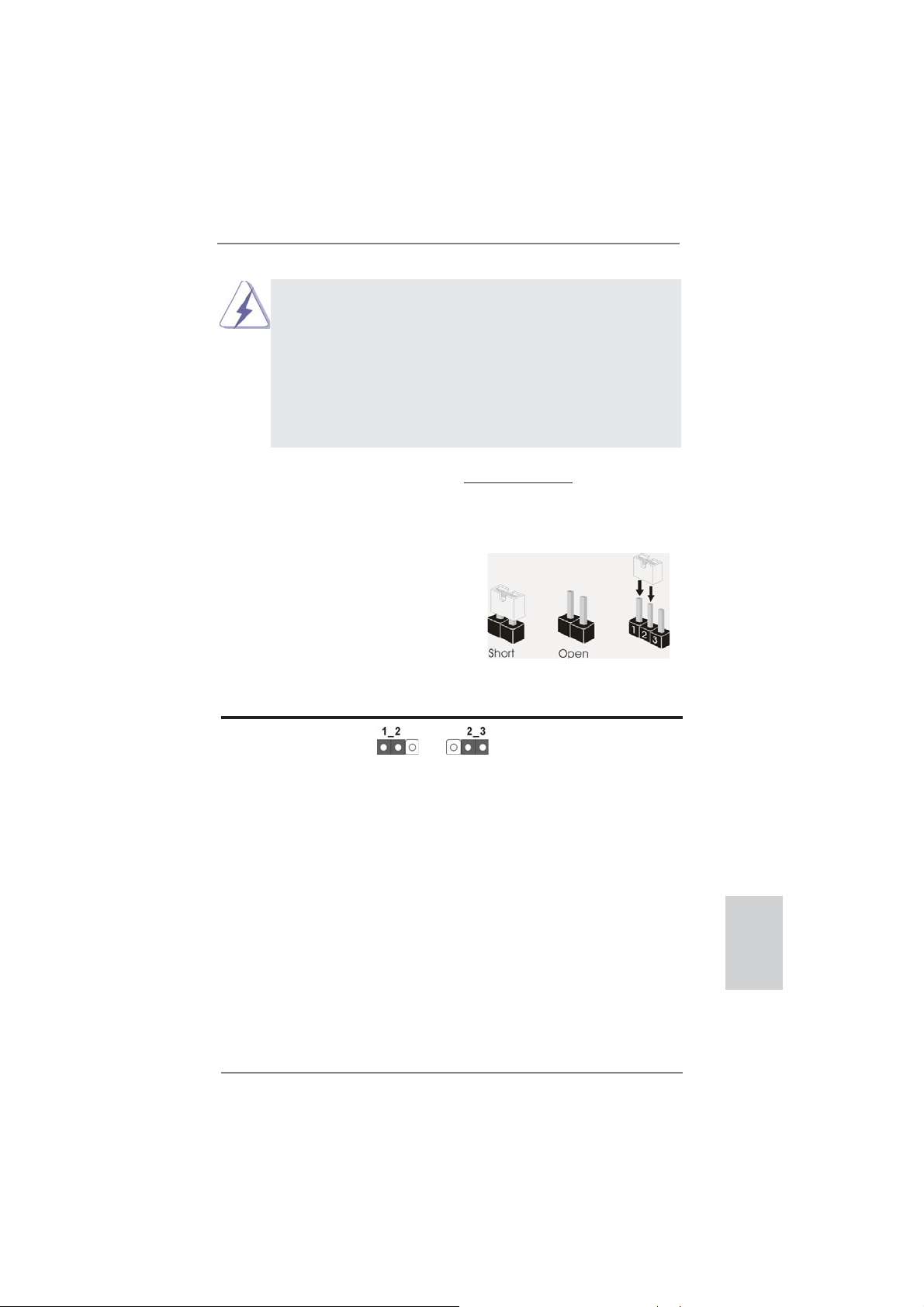
The illustration shows how jumpers are
setup. When the jumper cap is placed on
pins, the jumper is “Short”. If no jumper cap
is placed on pins, the jumper is “Open”. The
illustration shows a 3-pin jumper whose
pin1 and pin2 are “Short” when jumper cap
is placed on these 2 pins.
Jumper Setting Description
Clear CMOS Jumper
(CLRCMOS1)
(see p.2, No. 21)
Clear CMOSDefault
Note: CLRCMOS1 allows you to clear the data in CMOS. To clear and reset the
system parameters to default setup, please turn off the computer and unplug
the power cord from the power supply. After waiting for 15 seconds, use a
jumper cap to short pin2 and pin3 on CLRCMOS1 for 5 seconds. However,
please do not clear the CMOS right after you update the BIOS. If you need
to clear the CMOS when you just fi nish updating the BIOS, you must boot
up the system fi rst, and then shut it down before you do the clear-CMOS ac-
tion. Please be noted that the password, date, time, user default profi le, 1394
GUID and MAC address will be cleared only if the CMOS battery is removed.
English
2.8 Jumpers Setup
ASRock 970 Extreme3 Motherboard
21
Page 22
2.9 Onboard Headers and Connectors
Onboard headers and connectors are NOT jumpers. Do NOT place
jumper caps over these headers and connectors. Placing jumper caps
over the headers and connectors will cause permanent damage of the
motherboard!
Serial ATA3 Connectors These fi ve Serial ATA3
(SATA3_1: see p.2, No. 17)
(SATA3_2: see p.2, No. 18)
(SATA3_3: see p.2, No. 16)
(SATA3_4: see p.2, No. 19)
(SATA3_5: see p.2, No. 20)
Serial ATA (SATA) Either end of the SATA data
Data Cable cable can be connected to the
(Optional)
SATA / SATAII / SATA3 hard
disk or the SATA3 connector on
this motherboard.
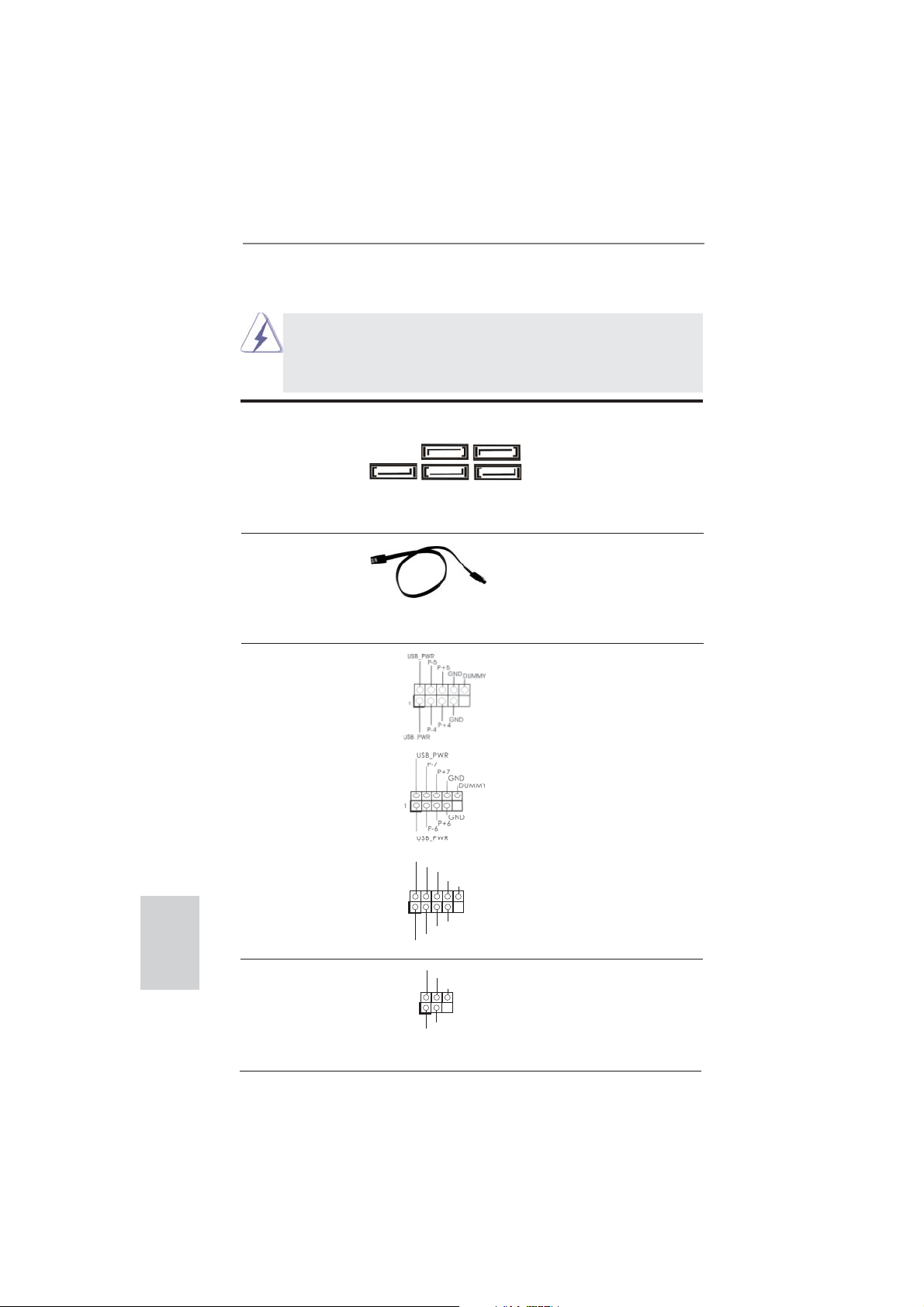
USB 2.0 Headers Besides four default USB 2.0
(9-pin USB_4_5)
(see p.2 No. 26)
ports on the I/O panel, there
are three USB 2.0 headers on
this motherboard. Each USB 2.0
header can support two USB
2.0 ports.
(9-pin USB_6_7)
(see p.2 No. 27)
(SATA3) connectors support
SATA3_3 SATA3_1
SATA data cables for internal
storage devices. The current
SATA3_5 SATA3_4 SATA3_2
SATA3 interface allows up to
6.0 Gb/s data transfer rate.
English
1
USB_PWR
P-9
P-8
USB_PWR
IRTX
+5VSB
1
IRRX
GND
P+9
GND
GND
P+8
DUMMY
DUMMY
(9-pin USB_8_9)
(see p.2 No. 28)
Infrared Module Header This header supports an
(5-pin IR1)
optional wireless transmitting
(see p.2 No. 29)
and receiving infrared module.
22
ASRock 970 Extreme3 Motherboard
Page 23
Consumer Infrared Module Header This header can be used to
(4-pin CIR1)
(see p.2 No. 25)
connect the remote
controller receiver.
1
ATX+5VSB
IRRX
IRTX
GND
1
GND
PRESENCE#
MIC2_R
MIC2_L
MIC_RET
J_SENSE
OUT2_R
OUT_RET
OUT2_L
Front Panel Audio Header This is an interface for the front
(9-pin HD_AUDIO1)
(see p.2 No. 32)
panel audio cable that allows
convenient connection and
control of audio devices.
1. High Defi nition Audio supports Jack Sensing, but the panel wire on
the chassis must support HDA to function correctly. Please follow the
instruction in our manual and chassis manual to install your system.
2. If you use AC’97 audio panel, please install it to the front panel audio
header as below:
A. Connect Mic_IN (MIC) to MIC2_L.
B. Connect Audio_R (RIN) to OUT2_R and Audio_L (LIN) to OUT2_L.
C. Connect Ground (GND) to Ground (GND).
D. MIC_RET and OUT_RET are for HD audio panel only. You don’t
need to connect them for AC’97 audio panel.
E. To activate the front mic.
For Windows
®
XP / XP 64-bit OS:
Select “Mixer”. Select “Recorder”. Then click “FrontMic”.
For Windows® 7 / 7 64-bit / VistaTM / VistaTM 64-bit OS:
Go to the "FrontMic" Tab in the Realtek Control panel. Adjust
“Recording Volume”.
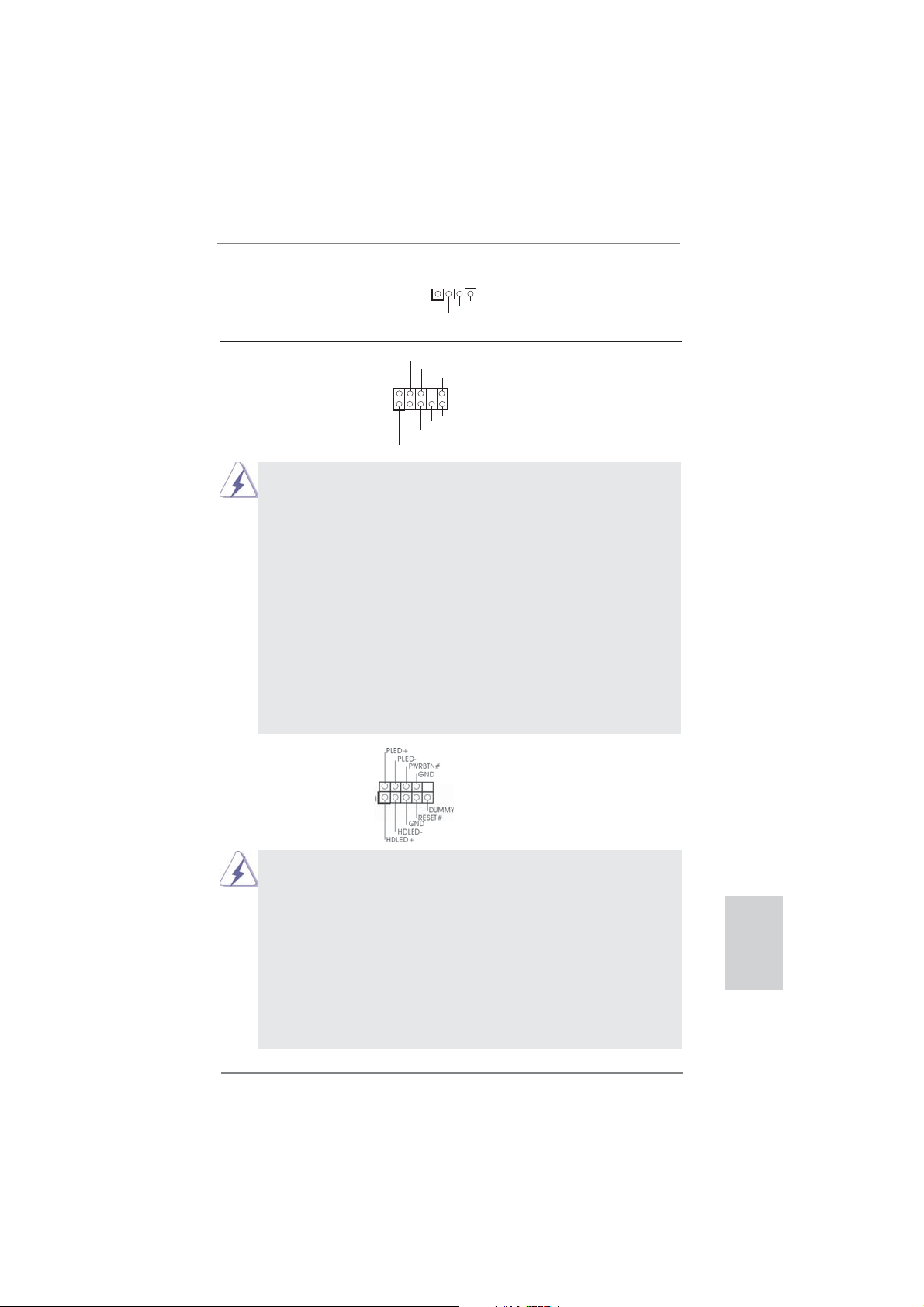
System Panel Header This header accommodates
(9-pin PANEL1)
(see p.2 No. 23)
several system front panel
functions.
Connect the power switch, reset switch and system status indicator
on the chassis to this header according to the pin assignments below.
Note the positive and negative pins before connecting the cables.
PWRBTN (Power Switch):
Connect to the power switch on the chassis front panel. You may confi gure the way to turn off your system using the power switch.
RESET (Reset Switch):
Connect to the reset switch on the chassis front panel. Press the reset
switch to restart the computer if the computer freezes and fails to perform a normal restart.
ASRock 970 Extreme3 Motherboard
English
23
Page 24
PLED (System Power LED):
Connect to the power status indicator on the chassis front panel. The
LED is on when the system is operating. The LED keeps blinking
when the sys-tem is in S1 sleep state. The LED is off when the system
is in S3/S4 sleep state or powered off (S5).
HDLED (Hard Drive Activity LED):
Connect to the hard drive activity LED on the chassis front panel. The
LED is on when the hard drive is reading or writing data.
The front panel design may differ by chassis. A front panel module
mainly consists of power switch, reset switch, power LED, hard drive
activity LED, speaker and etc. When connecting your chassis front
panel module to this header, make sure the wire assignments and the
pin assign-ments are matched correctly.
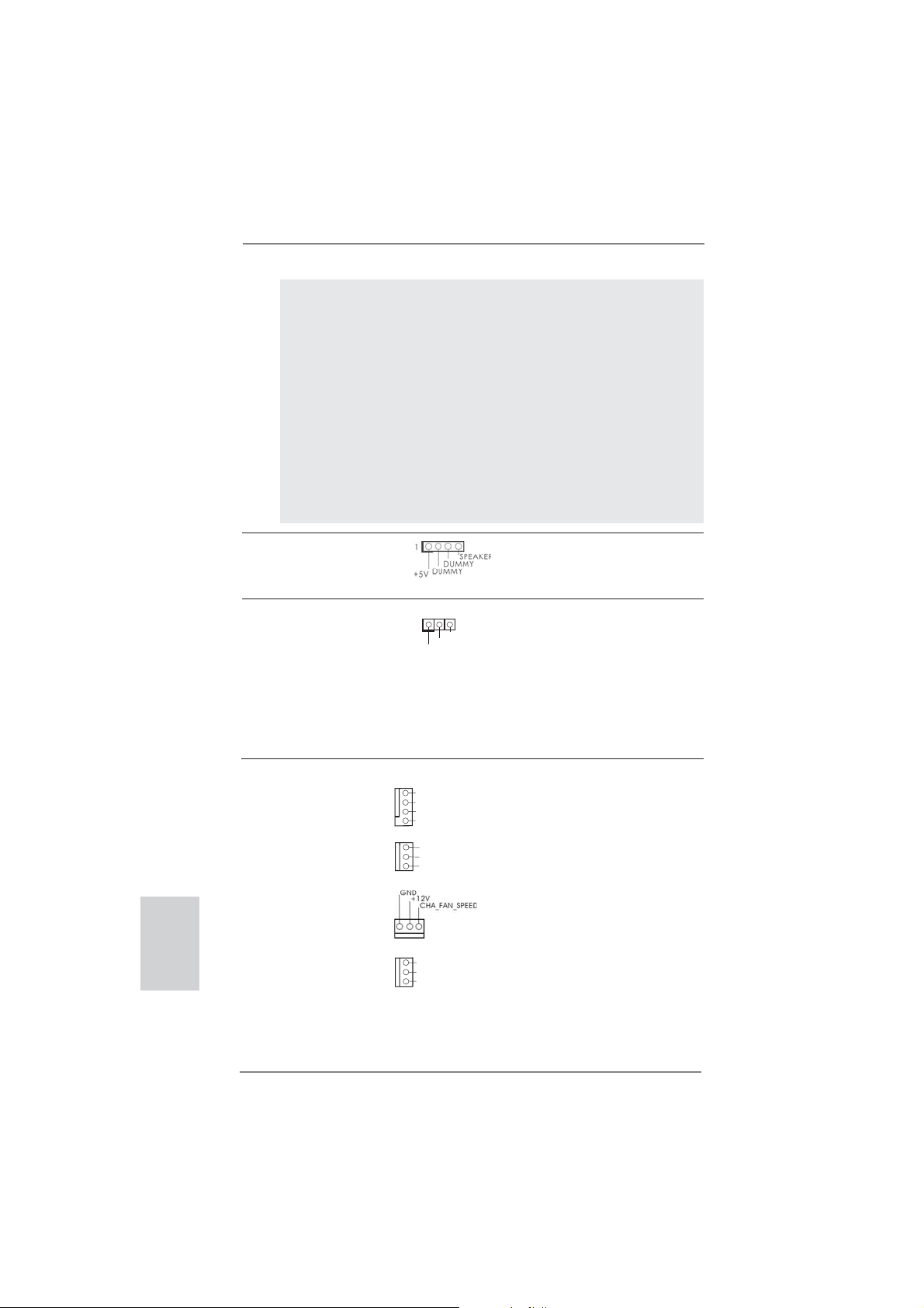
Chassis Speaker Header Please connect the chassis
(4-pin SPEAKER 1)
(see p.2 No. 24)
speaker to this header.
English
Power LED Header Please connect the chassis
(3-pin PLED1)
(see p.2 No. 22)
power LED to this header to
indicate system power status.
1
PLED+
PLED+
PLED-
The LED is on when the system
is operating. The LED keeps
blinking in S1 state. The LED is
off in S3/S4 state or S5 state
(power off).
Chassis and Power Fan Connectors Please connect the fan cables
(4-pin CHA_FAN1)
(see p.2 No. 12)
ground pin. CHA_FAN1/2/3 fan
(3-pin CHA_FAN2)
(see p.2 No. 15)
(3-pin CHA_FAN3)
(see p.2 No. 2)
(3-pin PWR_FAN1)
(see p.2 No. 10)
to the fan connectors and
match the black wire to the
GND
+12V
CHA_FAN_SPEED
FAN_SPEED_CONTROL
GND
+12V
CHA_FAN_SPEED
GND
+12V
PWR_FAN_SPEED
speed can be controlled through
UEFI or AXTU.
24
ASRock 970 Extreme3 Motherboard
Page 25
CPU Fan Connectors Please connect the CPU fan
(4-pin CPU_FAN1)
(see p.2 No. 6)
cable to the connector and
match the black wire to the
ground pin.
FAN_SPEED_CONTROL
CPU_FAN_SPEED
+12V
GND
1 2 3 4
Though this motherboard provides 4-Pin CPU fan (Quiet Fan) support, the 3-Pin
CPU fan still can work successfully even without the fan speed control function.
If you plan to connect the 3-Pin CPU fan to the CPU fan connector on this
motherboard, please connect it to Pin 1-3.
Pin 1-3 Connected
3-Pin Fan Installation
(3-pin CPU_FAN2)
(see p.2 No. 5)
GND
+12V
CPU_FAN_SPEED
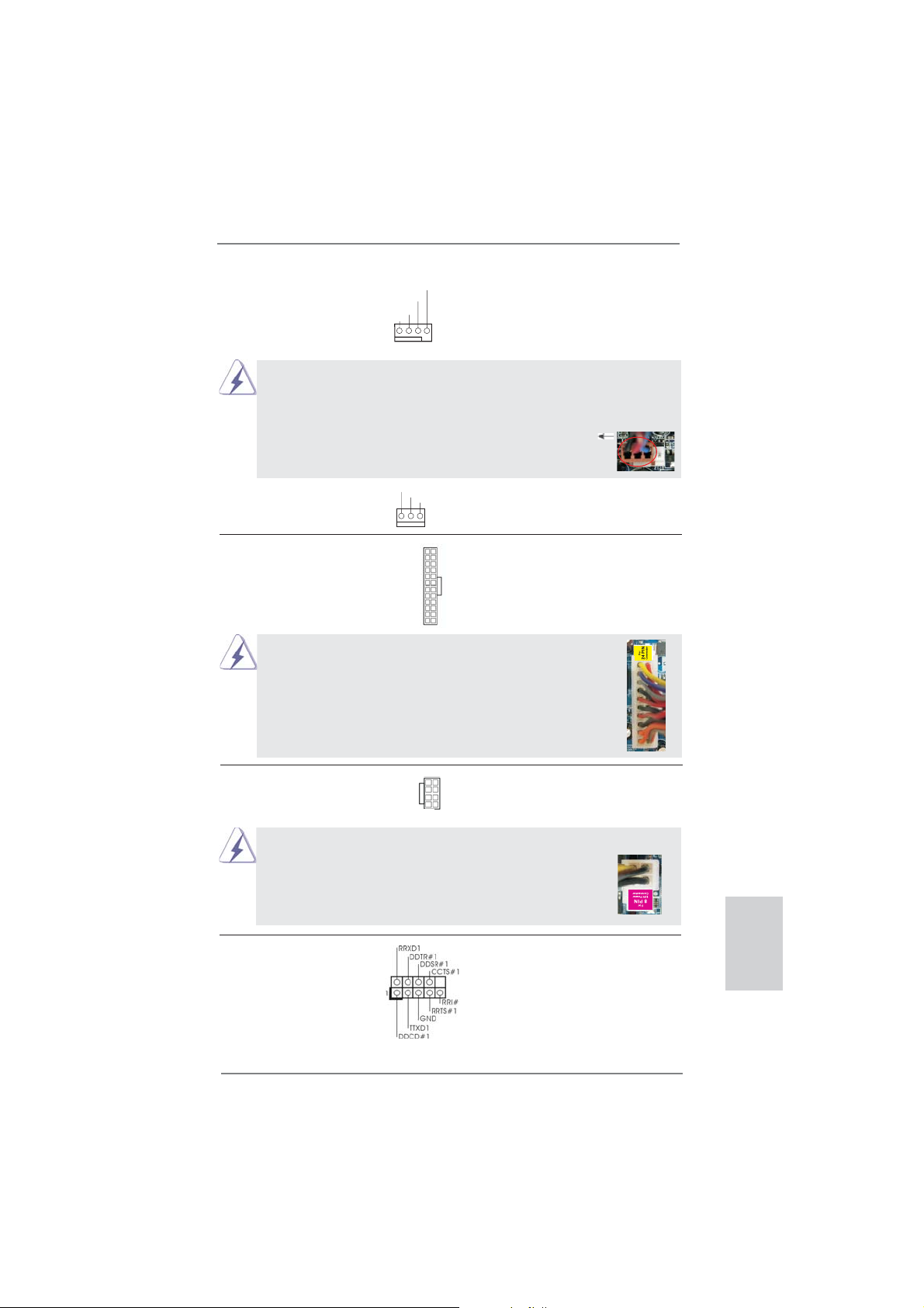
ATX Power Connector Please connect an ATX power
(24-pin ATXPWR1)
(see p.2 No. 9)
Though this motherboard provides 24-pin ATX power connector,
it can still work if you adopt a traditional 20-pin ATX power supply.
supply to this connector.
12
24
1
13
12
To use the 20-pin ATX power supply, please plug your power
supply along with Pin 1 and Pin 13.
20-Pin ATX Power Supply Installation
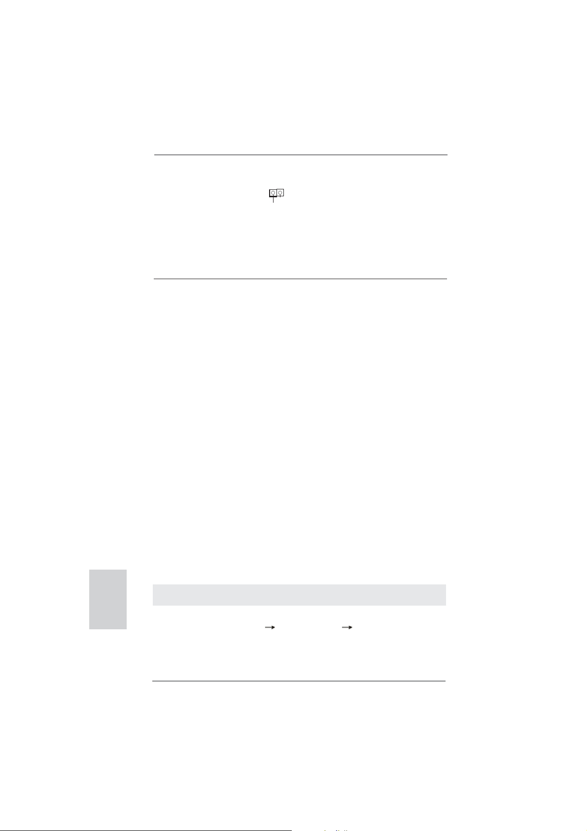
ATX 12V Power Connector Please connect an ATX 12V
(8-pin ATX12V1)
(see p.2 No. 1)
power supply to this connector.
5 1
8 4
1
Though this motherboard provides 8-pin ATX 12V power connector, it can still work
if you adopt a traditional 4-pin ATX 12V power supply. To use the
5 1
4-pin ATX power supply, please plug your power supply along with
Pin 1 and Pin 5.
4-Pin ATX 12V Power Supply Installation
8 4
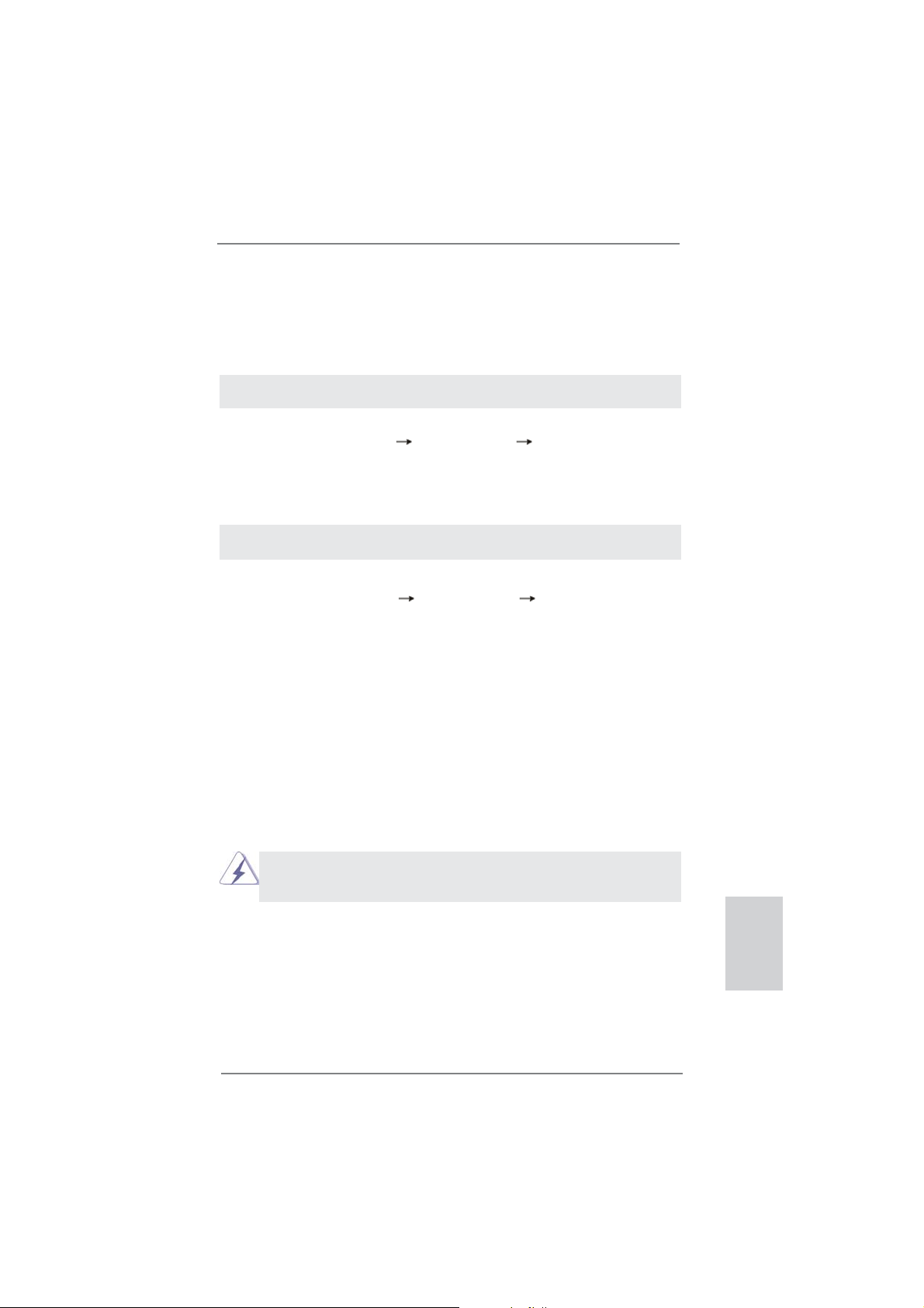
Serial port Header This COM1 header supports a
(9-pin COM1)
(see p.2 No.30)
serial port module.
24
13
English
ASRock 970 Extreme3 Motherboard
25
Page 26
HDMI_SPDIF Header HDMI_SPDIF header, providing
(2-pin HDMI_SPDIF1)
see p.2 No. 31)
(
VGA card, allows the system to
SPDIF audio output to HDMI
1
GND
SPDIFOUT
connect HDMI Digital TV/
projector/LCD devices. Please
connect the HDMI_SPDIF
connector of HDMI VGA card to
this header.
2.10 Driver Installation Guide
To install the drivers to your system, please insert the support CD to your optical
drive fi rst. Then, the drivers compatible to your system can be auto-detected and
listed on the support CD driver page. Please follow the order from up to bottom side
to install those required drivers. Therefore, the drivers you install can work properly.
2.11 Installing Windows® 7 / 7 64-bit / VistaTM / VistaTM 64-bit / XP /
XP 64-bit With RAID Functions
If you want to install Windows® 7 / 7 64-bit / VistaTM / VistaTM 64-bit / XP / XP 64bit on your SATA3 HDDs with RAID functions, please refer to the document at the
following path in the Support CD for detailed procedures:
..\ RAID Installation Guide
2.12 Installing Windows® 7 / 7 64-bit / VistaTM / VistaTM 64-bit / XP /
XP 64-bit Without RAID Functions
If you want to install Windows® 7 / 7 64-bit / VistaTM / VistaTM 64-bit / XP / XP 64-bit
OS on your SATA3 HDDs without RAID functions, please follow below procedures
according to the OS you install.
English
2.12.1 Installing Windows® XP / XP 64-bit Without RAID Functions
If you want to install Windows® XP / XP 64-bit on your SATA3 HDDs without RAID
functions, please follow below steps.
Using SATA3 HDDs without NCQ and Hot Plug functions (IDE mode)
STEP 1: Set up UEFI.
A. Enter UEFI SETUP UTILITY Advanced screen Storage Confi guration.
B. Set the “SATA Mode” option to [IDE].
STEP 2: Install Windows
26
®
XP / XP 64-bit OS on your system.
ASRock 970 Extreme3 Motherboard
Page 27
2.12.2 Installing Windows® 7 / 7 64-bit / VistaTM / VistaTM 64-bit
Without RAID Functions
If you want to install Windows® 7 / 7 64-bit / VistaTM / VistaTM 64-bit on your SATA3
HDDs without RAID functions, please follow below steps.
Using SATA3 HDDs without NCQ and Hot Plug functions (IDE mode)
STEP 1: Set up UEFI.
A. Enter UEFI SETUP UTILITY Advanced screen Storage Confi guration.
B. Set the “SATA Mode” option to [IDE].
STEP 2: Install Windows
tem.
Using SATA3 HDDs with NCQ and Hot Plug functions (AHCI mode)
STEP 1: Set up UEFI.
A. Enter UEFI SETUP UTILITY Advanced screen Storage Confi guration.
B. Set the “SATA Mode” option to [AHCI].
STEP 2: Install Windows
system.
®
7 / 7 64-bit / VistaTM / VistaTM 64-bit OS on your sys-
®
7 / 7 64-bit / VistaTM / VistaTM 64-bit OS on your
2.13 Untied Overclocking Technology
This motherboard supports Untied Overclocking Technology, which means during
overclocking, FSB enjoys better margin due to fi xed PCI / PCIE buses. Before you
enable Untied Overclocking function, please enter “Overclock Mode” option of UEFI
setup to set the selection from [Auto] to [Manual]. Therefore, CPU FSB is untied
during overclocking, but PCI / PCIE buses are in the fi xed mode so that FSB can
operate under a more stable overclocking environment.
Please refer to the warning on page 8 for the possible overclocking risk
before you apply Untied Overclocking Technology.
ASRock 970 Extreme3 Motherboard
English
27
Page 28

3. BIOS Information
The Flash Memory on the motherboard stores BIOS Setup Utility. When you start up
the computer, please press <F2> or <Del> during the Power-On-Self-Test (POST)
to enter BIOS Setup utility; otherwise, POST continues with its test routines. If you
wish to enter BIOS Setup after POST, please restart the system by pressing <Ctl>
+ <Alt> + <Delete>, or pressing the reset button on the system chassis. The BIOS
Setup program is designed to be user-friendly. It is a menu-driven program, which
allows you to scroll through its various sub-menus and to select among the predetermined choices. For the detailed information about BIOS Setup, please refer to the
User Manual (PDF fi le) contained in the Support CD.
4. Software Support CD information
®
This motherboard supports various Microsoft
64-bit / VistaTM / Vista
motherboard contains necessary drivers and useful utilities that will enhance motherboard features. To begin using the Support CD, insert the CD into your CD-ROM
drive. It will display the Main Menu automatically if “AUTORUN” is enabled in your
computer. If the Main Menu does not appear automatically, locate and double-click
on the fi le “ASSETUP.EXE” from the BIN folder in the Support CD to display the
menus.
TM
64-bit / XP / XP 64-bit. The Support CD that came with the
Windows® operating systems: 7 / 7
English
28
ASRock 970 Extreme3 Motherboard
Page 29
1. Einführung
Wir danken Ihnen für den Kauf des ASRock 970 Extreme3 Motherboard, ein zuverlässiges Produkt, welches unter den ständigen, strengen Qualitätskontrollen von
ASRock gefertigt wurde. Es bietet Ihnen exzellente Leistung und robustes Design,
gemäß der Verpflichtung von ASRock zu Qualität und Halbarkeit. Diese Schnellinstallationsanleitung führt in das Motherboard und die schrittweise Installation
ein. Details über das Motherboard fi nden Sie in der Bedienungsanleitung auf der
Support-CD.
Da sich Motherboard-Spezifi kationen und BIOS-Software verändern
können, kann der Inhalt dieses Handbuches ebenfalls jederzeit geändert
werden. Für den Fall, dass sich Änderungen an diesem Handbuch
ergeben, wird eine neue Version auf der ASRock-Website, ohne weitere
Ankündigung, verfügbar sein. Die neuesten Grafi kkarten und unterstützten
CPUs sind auch auf der ASRock-Website aufgelistet.
ASRock-Website: http://www.asrock.com
Wenn Sie technische Unterstützung zu Ihrem Motherboard oder spezifi sche
Informationen zu Ihrem Modell benötigen, besuchen Sie bitte unsere
Webseite:
www.asrock.com/support/index.asp
1.1 Kartoninhalt
ASRock 970 Extreme3 Motherboard
(ATX-Formfaktor: 30.5 cm x 21.8 cm; 12.0 Zoll x 8.6 Zoll)
ASRock 970 Extreme3 Schnellinstallationsanleitung
ASRock 970 Extreme3 Support-CD
Zwei Serial ATA (SATA) -Datenkabel (optional)
Ein I/O Shield
ASRock erinnert...
Zur besseren Leistung unter Windows® 7 / 7, 64 Bit / Vista
64 Bit empfehlen wir, die Speicherkonfi guration im BIOS auf den AHCI-
Modus einzustellen. Hinweise zu den BIOS-Einstellungen fi nden Sie in
der Bedienungsanleitung auf der mitgelieferten CD.
TM
/ VistaTM
ASRock 970 Extreme3 Motherboard
Deutsch
29
Page 30
Deutsch
1.2 Spezifikationen
Plattform - ATX-Formfaktor: 30.5 cm x 21.8 cm; 12.0 Zoll x 8.6 Zoll
- Alle Feste Kondensatordesign (100% in Japan gefertigte,
erstklassige leitfähige Polymer-Kondensatoren)
CPU - Unterstützung von Socket AM3+-Prozessoren
- Unterstützung von Socket AM3-Prozessoren: AMD
Phenom
X3 / X2 / Sempron-Prozessor
- Acht-Kern-CPU-bereit
- Unterstützt UCC (Unlock CPU Core) (siehe VORSICHT 1)
- V4 + 1-Stromphasendesign
- Unterstützt CPU bis 140W
- Unterstützt Cool ‘n’ Quiet
- FSB 2400 MHz (4.8 GT/s)
- Unterstützt Untied-Übertaktungstechnologie
(siehe VORSICHT 2)
- Unterstützt Hyper-Transport- 3.0 Technologie (HT 3.0)
Chipsatz - Northbridge: AMD 970
- Southbridge: AMD SB950
Speicher - Unterstützung von Dual-Kanal-Speichertechnologie
(siehe VORSICHT 3)
- 4 x Steckplätze für DDR3
- Unterstützt DDR3 2100(OC)1866(OC)/1800(OC)/1600(OC)
/1333/1066/800 non-ECC, ungepufferter Speicher
(siehe VORSICHT 4)
- Max. Kapazität des Systemspeichers: 32GB
(siehe VORSICHT 5)
Erweiterungs- - 2 x PCI-Express-2.0-x16-Steckplätze
Steckplätze (PCIE2: x16-Modus; PCIE4: x4-Modus)
- 2 x PCI Express 2.0 x1-Steckplätze
- 2 x PCI -Steckplätze
- Unterstützt AMD
Audio - 7.1 CH HD Audio mit dem Inhalt Schutz
(Realtek ALC892 Audio Codec)
- Premium Blu-ray-Audio-Unterstützung
- Unterstützt THX TruStudio
LAN - PCIE x1 Gigabit LAN 10/100/1000 Mb/s
- Realtek RTL8111E
- Unterstützt Wake-On-LAN
- Unterstützt LAN-Kabelerkennung
TM
II X6 / X4 / X3 / X2 (außer 920 / 940) / Athlon X4 /
TM
-Technologie von AMD
TM
Quad CrossFireXTM und CrossFireX
TM
TM
30
ASRock 970 Extreme3 Motherboard
Page 31

- Unterstützt energieeffi zientes Ethernet 802.3az
- Unterstützt PXE
E/A-Anschlüsse I/O Panel
an der - 1 x PS/2-Mausanschluss
Rückseite - 1 x PS/2-Tastaturanschluss
- 1 x Koaxial-SPDIF-Ausgang
- 1 x optischer SPDIF-Ausgang
- 4 x Standard-USB 2.0-Anschlüsse
- 2 x Standard-USB 3.0-Anschlüsse
- 1 x eSATA3-Anschluss
- 1 x RJ-45 LAN Port mit LED (ACT/LINK LED und SPEED
LED)
- HD Audiobuchse: Lautsprecher seitlich / Lautsprecher
hinten / Mitte/Bass / Audioeingang/ Lautsprecher vorne /
Mikrofon (siehe VORSICHT 6)
SATA3 - 5 x SATA 3-Anschluss mit 6,0 Gb/s, unterstützt RAID (RAID 0, RAID 1, RAID 5 und RAID 10), NCQ-, AHCI- und
„Hot Plugging“-Funktionen
USB3.0 - 2 x USB 3.0-Ports an der Rückseite durch Etron EJ168A,
unterstützt USB 1.0/2.0/3.0 mit bis zu 5 Gb/s
Anschlüsse - 5 x SATA3 6,0 GB/s-Anschlüsse
- 1 x Infrarot-Modul-Header
- 1 x
- 1 x COM-Anschluss-Header
- 1 x HDMI_SPDIF-Anschluss
- 1 x Betriebs-LED-Header
- CPU/Gehäuse/Stromlüfter-Anschluss
- 24-pin ATX-Netz-Header
- 8-pin anschluss für 12V-ATX-Netzteil
- Anschluss für Audio auf der Gehäusevorderseite
- 3 x USB 2.0-Anschlüsse (Unterstützung 6 zusätzlicher
USB 2.0-Anschlüsse)
BIOS - 32Mb AMIs Legal BIOS UEFI mit GUI-Unterstützung
- Unterstützung für “Plug and Play”
- ACPI 1.1-Weckfunktionen
- JumperFree-Modus
- SMBIOS 2.3.1
- CPU, VCCM, NB, SB Stromspannung Multianpassung
Consumer Infrarot-Modul-Header
Deutsch
ASRock 970 Extreme3 Motherboard
31
Page 32
Deutsch
Support-CD - Treiber, Dienstprogramme, Antivirussoftware
(Probeversion), CyberLink MediaEspresso 6.5-Testversion,
AMD OverDrive
TM
-Dienstprogramm, AMD Fusion, AMD
Fusion Media Explorer, ASRock-Software-Suite (CyberLink
DVD Suite - OEM- und Testversion; ASRock MAGIX Multimedia-Suite - OEM)
Einzigartige - ASRock Extreme Tuning Utility (AXTU)
Eigenschaft (siehe VORSICHT 7)
- ASRock Sofortstart
- ASRock Instant Flash (siehe VORSICHT 8)
- ASRock APP Charger (siehe VORSICHT 9)
- ASRock SmartView (siehe VORSICHT 10)
- ASRock XFast USB (siehe VORSICHT 11)
- ASRock XFast LAN (siehe VORSICHT 12)
- ASRock ein/aus-Wiedergabetechnologie
(siehe VORSICHT 13)
- Hybrid Booster:
- Schrittloser CPU-Frequenz-Kontrolle
(siehe VORSICHT 14)
- ASRock U-COP (siehe VORSICHT 15)
- Boot Failure Guard (B.F.G. – Systemstartfehlerschutz)
- Turbo UCC
Hardware Monitor - CPU-Temperatursensor
- Motherboardtemperaturerkennung
- Drehzahlmessung für CPU/Gehäuse/Stromlüfter
- CPU-/Gehäuselüftergeräuschdämpfung
- Mehrstufi ge Geschwindigkeitsteuerung für CPU-/
Gehäuselüfter
- Spannungsüberwachung: +12V, +5V, +3.3V, Vcore
®
Betriebssysteme - Unterstützt Microsoft
Vista
TM
64-Bit / XP / XP 64-Bit
Windows® 7 / 7 64-Bit / VistaTM /
Zertifi zierungen - FCC, CE, WHQL
- Gemäß Ökodesign-Richtlinie (ErP/EuP) (Stromversorgung
gemäß Ökodesign-Richtlinie (ErP/EuP) erforderlich)
(siehe VORSICHT 16)
* Für die ausführliche Produktinformation, besuchen Sie bitte unsere Website:
http://www.asrock.com
32
ASRock 970 Extreme3 Motherboard
Page 33

WARNUNG
Beachten Sie bitte, dass Overclocking, einschließlich der Einstellung im BIOS, Anwenden
der Untied Overclocking-Technologie oder Verwenden von Overclocking-Werkzeugen von
Dritten, mit einem gewissen Risiko behaftet ist. Overclocking kann sich nachteilig auf die
Stabilität Ihres Systems auswirken oder sogar Komponenten und Geräte Ihres Systems
beschädigen. Es geschieht dann auf eigene Gefahr und auf Ihre Kosten. Wir übernehmen
keine Verantwortung für mögliche Schäden, die aufgrund von Overclocking verursacht wurden.
VORSICHT!
1. Die ASRock UCC-Funktion (Unlock CPU Core; zu Deutsch: CPU-Kern
freigeben) vereinfacht die AMD-CPU-Aktivierung. Zur Freigabe des zusätzlichen CPU-Kerns müssen Sie lediglich die UEFI-Option „Unlock CPU Core“
(zu Deutsch: CPU-Kern freigeben) umschalten – schon profi tieren Sie von
einem Leistungsschub. Wenn die UCC-Funktion aktiviert ist, rüstet die DualCore- oder Triple-Core-CPU auf eine Quad-Core-CPU auf – einige CPUs
(inklusive Quad-Core) können zudem die L3-Cache-Größe auf bis zu 6 MB
anheben; das bedeutet verbesserte CPU-Leistung zu einem geringeren
Preis. Bitte beachten Sie, dass die UCC-Funktion nur bei AM3/AM3+-CPUs
einsetzbar ist; die Unterstützung besteht jedoch aufgrund möglicher Fehlfunktionen des verborgenen Kerns einiger CPUs auch nicht zwangsläufi g
bei jeder AM3/AM3+-CPU.
2. Dieses Motherboard unterstützt die Untied-Übertaktungstechnologie.
Unter “Entkoppelte Übertaktungstechnologie” auf Seite 27 fi nden Sie detail-
lierte Informationen.
Dieses Motherboard unterstützt Dual-Kanal-Speichertechnologie. Vor
3.
Implementierung der Dual-Kanal-Speichertechnologie müssen Sie die
Installationsanleitung für die Speichermodule auf Seite 14 zwecks richtiger
Installation gelesen haben.
4. Ob die Speichergeschwindigkeit 2100/1866/1800/1600 MHz unterstützt wird, hängt von der von Ihnen eingesetzten AM3/AM3+-CPU ab.
Schauen Sie bitte auf unseren Internetseiten in der Liste mit unterstützten Speichermodulen nach, wenn Sie DDR3 2100/1866/1800/1600-Speichermodule einsetzen möchten. AM3+ CPU unterstützt DDR3 1866 ohne
Übertaktung (OC Mode).
ASRock-Internetseite: http://www.asrock.com
5. Durch Betriebssystem-Einschränkungen kann die tatsächliche Speichergröße weniger als 4 GB betragen, da unter Windows
etwas Speicher zur Nutzung durch das System reserviert wird. Unter
®
Windows
6. Der Mikrofoneingang dieses Motherboards unterstützt Stereo- und MonoModi. Der Audioausgang dieses Motherboards unterstützt 2-Kanal-,
4-Kanal-, 6-Kanal- und 8-Kanal-Modi. Stellen Sie die richtige Verbindung
anhand der Tabelle auf Seite 3 her.
OS mit 64-Bit-CPU besteht diese Einschränkung nicht.
®
7 / Vista™ / XP
Deutsch
ASRock 970 Extreme3 Motherboard
33
Page 34

Deutsch
7. ASRock Extreme Tuning Utility (AXTU) ist ein Alles-in-einem Werkzeug zur Feineinstellung verschiedener Systemfunktionen an
einer benutzerfreundlichen Schnittstelle; diese beinhaltet
HardwareÜberwachung, Lüftersteuerung, Übertaktung, OC DNA und
IES. Über die Hardware-Überwachung können Sie die Hauptsystemdaten einsehen. Die Lüftersteuerung zeigt Ihnen zur Anpassung
Lüftergeschwindigkeit und Temperatur an. Bei der Übertaktung können
Sie die CPU-Frequenz zur Erzielung optimaler Systemleistung übertakten. OC DNA ermöglicht Ihnen die Speicherung Ihrer OCEinstellungen als Profi l, welches Sie mit Freunden teilen können. Ihre
Freunde können das OC-Profi l dann in ihrem System laden und so die
gleichen OC-Einstellungen erzielen. Per IES (Intelligent Energy Saver)
kann der Spannungsregulator bei Inaktivität der CPU-Kerne die Anzahl
an Ausgangsphasen zur Steigerung der Effi zienz reduzieren – ohne die
Rechenleistung zu beeinträchtigen. Hinweise zur Bedienung der ASRock
Extreme Tuning Utility (AXTU) fi nden Sie auf unserer Webseite.
ASRock-Webseite: http://www.asrock.com
8. ASRock Instant Flash ist ein im Flash-ROM eingebettetes BIOS-Flash-
Programm. Mithilfe dieses praktischen BIOS-Aktualisierungswerkzeugs
können Sie das System-BIOS aktualisieren, ohne dafür zuerst Betriebssysteme wie MS-DOS oder Windows
Programm bekommen Sie durch Drücken der <F6>-Taste während des
POST-Vorgangs oder durch Drücken der <F2>-Taste im BIOS-SetupMenü Zugang zu ASRock Instant Flash. Sie brauchen dieses Werkzeug
einfach nur zu starten und die neue BIOS-Datei auf Ihrem USB-FlashLaufwerk, Diskettenlaufwerk oder der Festplatte zu
speichern, und schon können Sie Ihr BIOS mit nur wenigen Klickvorgän-
gen ohne Bereitstellung einer zusätzlichen Diskette oder eines anderen komplizierten Flash-Programms aktualisieren. Achten Sie darauf,
dass das USB-Flash-Laufwerk oder die Festplatte das Dateisystem
FAT32/16/12 benutzen muss.
9. Wenn Sie nach einer schnelleren, weniger eingeschränkten Möglich-
keit zur Aufl adung Ihrer Apple-Geräte (z. B. iPhone/iPad/iPod touch)
suchen, bietet ASRock Ihnen eine wunderbare Lösung – den ASRock
APP Charger. Installieren Sie einfach den ASRock APP Charger-Treiber;
dadurch lädt sich Ihr iPhone wesentlich schneller über einen Computer
auf – genaugenommen bis zu 40 % schneller als zuvor. Der ASRock APP
Charger ermöglicht Ihnen die schnelle Aufl adung mehrerer Apple-Geräte
gleichzeitig; der Ladevorgang wird sogar dann fortgesetzt, wenn der PC
den Ruhezustand (S1), Suspend to RAM-Modus (S3) oder Tiefschlafmodus (S4) aufruft oder ausgeschaltet wird (S5). Nach der
Installation des APP Charger-Treibers können Sie im Handumdrehen das
großartigste Ladeerlebnis überhaupt genießen.
ASRock-Webseite: http://www.asrock.com/Feature/AppCharger/index.
asp
®
aufrufen zu müssen. Mit diesem
34
ASRock 970 Extreme3 Motherboard
Page 35

10. SmartView, eine neue Internetbrowserfunktion, ist eine intelligente IE-
Startseite, die meist besuchte Internetseiten, Ihren Browserverlauf,
Facebook-Freunde und Nachrichten in Echtzeit miteinander kombiniert:
In einer speziellen Ansicht, die das Internet noch angenehmer und aufregender macht. ASRock-Motherboards werden exklusiv mit der SmartView-Software geliefert, die auch dafur sorgt, dass Sie immer mit Ihren
Freunden in Verbindung bleiben. Die SmartView-Funktionen konnen Sie
mit den Windows
und dem Internet Explorer ab Version 8 nutzen.
ASRock-Website: http://www.asrock.com/Feature/SmartView/index.asp
11. ASRocks XFast USB dient der Steigerung der Leistungsfähigkeit Ihrer
USB-Speichergeräte. Die Leistung kann je nach Eigenschaften des
Gerätes variieren.
12. ASRock XFast LAN bietet einen schnelleren Internetzugang mit den
nachfolgenden Vorteilen. LAN-Anwendungspriorisierung: Hiermit konfi gurieren Sie auf ideale Weise Ihre Anwendungspriorität und/oder fügen
neue Programme hinzu. Niedrigere Latenzzeit bei Spielen: Nach Einstellung einer höheren Online-Gamepriorität kann hiermit die Latenzzeit bei
Spielen herabgesetzt werden. Datenverkehrsgestaltung: Sie können
Youtube-Videos in HD anzeigen und gleichzeitig Dateien herunterladen.
Echtzeitanalyse Ihrer Daten: Über das Statusfenster können Sie schnell
ermitteln, welche Datenströme zur Zeit übertragen werden.
13. Durch die ASRock ein/aus-Wiedergabetechnologie können Sie großartige
Klangerlebnisse von portablen Audiogeräten, wie z. B. MP3-Playern oder
Mobiltelefonen, an Ihrem PC genießen – selbst wenn der PC ausgeschaltet ist (oder sich im ACPI S5-Modus befi ndet)! Dieses Motherboard
wird zudem mit einem kostenlosen Audiokabel (3,5 mm, Klinke) (optional)
geliefert, was eine IT-Umgebung von höchster Benutzerfreundlichkeit
gewährleistet.
14. Obwohl dieses Motherboard stufenlose Steuerung bietet, wird Over-
clocking nicht empfohlen. Frequenzen, die von den empfohlenen CPUBusfrequenzen abweichen, können Instabilität des Systems verursachen
oder die CPU beschädigen.
15. Wird eine Überhitzung der CPU registriert, führt das System einen automati-
schen Shutdown durch. Bevor Sie das System neu starten, prüfen Sie bitte,
ob der CPU-Lüfter am Motherboard richtig funktioniert, und stecken Sie bitte
den Stromkabelstecker aus und dann wieder ein. Um die Wärmeableitung
zu verbessern, bitte nicht vergessen, etwas Wärmeleitpaste zwischen CPU
und Kühlkörper zu sprühen.
16. EuP steht für Energy Using Product und kennzeichnet die Ökodesign-
Richtlinie, die von der Europäischen Gemeinschaft zur Festlegung des
Energieverbrauchs von vollständigen Systemen in Kraft gesetzt wurde.
Gemäß dieser Ökodesign-Richtlinie (EuP) muss der gesamte Netzstromverbrauch von vollständigen Systemen unter 1,00 Watt liegen, wenn sie
ausgeschaltet sind. Um dem EuP-Standard zu entsprechen, sind ein EuPfähiges Motherboard und eine EuP-fähige Stromversorgung erforderlich.
Gemäß einer Empfehlung von Intel muss eine EuP-fähige Stromversorgung
®
-Betriebssystemen 7 / 7, 64 Bit / VistaTM / VistaTM 64 Bit
Deutsch
ASRock 970 Extreme3 Motherboard
35
Page 36

Deutsch
dem Standard entsprechen, was bedeutet, dass bei einem Stromverbrauch
von 100 mA die 5-Volt-Standby-Energieeffi zienz höher als 50% sein sollte.
Für die Wahl einer EuP-fähigen Stromversorgung empfehlen wir Ihnen,
weitere Details beim Hersteller der Stromversorgung abzufragen.
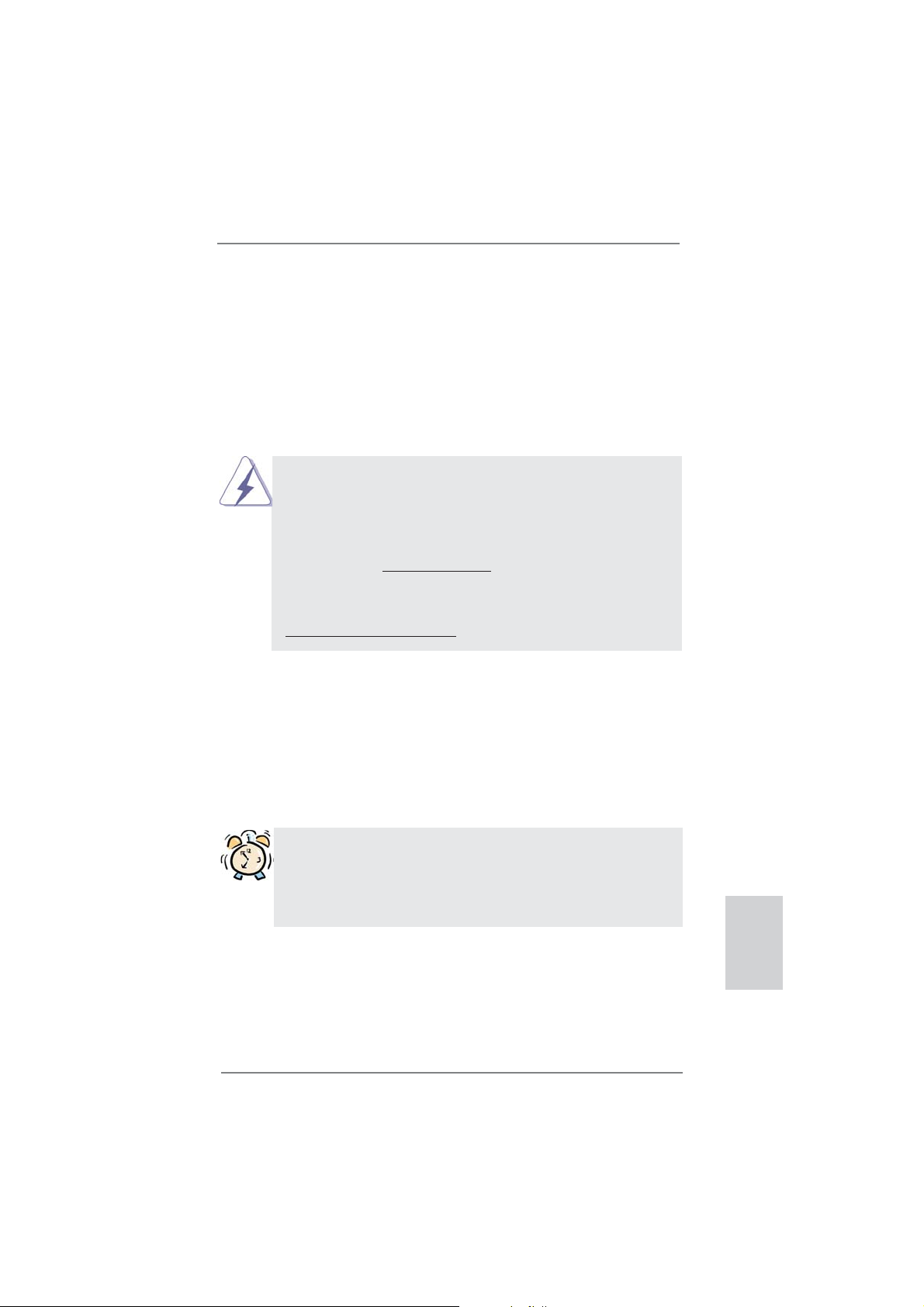
1.3 Einstellung der Jumper
Die Abbildung verdeutlicht, wie Jumper
gesetzt werden. Werden Pins durch
Jumperkappen verdeckt, ist der Jumper
“gebrückt”. Werden keine Pins durch Jumperkappen verdeckt, ist der Jumper “offen”.
Die Abbildung zeigt einen 3-Pin Jumper
dessen Pin1 und Pin2 “gebrückt” sind, bzw.
es befindet sich eine Jumper-Kappe auf
diesen beiden Pins.
Jumper Einstellun
CMOS löschen
(CLRCMOS1, 3-Pin jumper)
(siehe S.2, No. 21)
DefaultEinstellung
Hinweis: CLRCMOS1 erlaubt Ihnen das Löschen der CMOS-Daten. Diese beinhal-
ten das System-Passwort, Datum, Zeit und die verschiedenen BIOS-Parameter. Um die Systemparameter zu löschen und auf die Werkseinstellung
zurückzusetzen, schalten Sie bitte den Computer ab und entfernen das
Stromkabel. Benutzen Sie eine Jumperkappe, um die
Pin 2 und Pin 3 an CLRCMOS1 für 5 Sekunden kurzzuschließen. Bitte
vergessen Sie nicht, den Jumper wieder zu entfernen, nachdem das
CMOS gelöscht wurde. Bitte vergessen Sie nicht, den Jumper wieder zu
entfernen, nachdem das CMOS gelöscht wurde. Wenn Sie den CMOSInhalt gleich nach dem Aktualisieren des BIOS löschen müssen, müssen
Sie zuerst das System starten und dann wieder ausschalten, bevor Sie
den CMOS-Inhalt löschen.
CMOS
löschen
36
ASRock 970 Extreme3 Motherboard
Page 37

1.4 Anschlüsse
Anschlussleisten sind KEINE Jumper. Setzen Sie KEINE Jumperkappen
auf die Pins der Anschlussleisten. Wenn Sie die Jumperkappen auf die
Anschlüsse setzen, wird das Motherboard permanent beschädigt!
Anschluss Beschreibung
Seriell-ATA3-Anschlüsse Diese fünf Serial ATA3-
(SATA3_1: siehe S.2 - No. 17)
(SATA3_2: siehe S.2 - No. 18)
(SATA3_3: siehe S.2 - No. 16)
(SATA3_4: siehe S.2 - No. 19)
(SATA3_5: siehe S.2 - No. 20)
(SATA3-)Verbínder
unterstützten SATA-Datenkabel
für interne
SATA3_5 SATA3_4 SATA3_2
Massenspeichergeräte. Die
aktuelle SATA3- Schnittstelle
ermöglicht eine
Datenübertragungsrate bis
6,0 Gb/s.
Serial ATA- (SATA-) SJedes Ende des SATA
Datenkabel Datenkabels kann an die
(Option)
SATA / SATAII / SATA3
Festplatte oder das SATA3
Verbindungsstück auf dieser
Hauptplatine angeschlossen
werden.
SATA3_3 SATA3_1
USB 2.0-Header Zusätzlich zu den vier
(9-pol. USB_4_5)
(siehe S.2 - No. 26)
üblichen USB 2.0-Ports an den
I/O-Anschlüssen befi nden sich
drei USB 2.0-
Anschlussleisten am
Motherboard. Pro USB 2.0-
(9-pol. USB_6_7)
(siehe S.2 - No. 27)
(9-pol. USB_8_9)
(siehe S.2 - No. 28)
Anschlussleiste werden zwei
USB 2.0-Ports unterstützt.
USB_PWR
P-9
P+9
GND
DUMMY
1
GND
P+8
P-8
USB_PWR
ASRock 970 Extreme3 Motherboard
Deutsch
37
Page 38

Infrarot-Modul-Header Dieser Header unterstützt ein
(5-pin IR1)
optionales, drahtloses Sende-
(siehe S.2 - No. 29)
und Empfangs-Infrarotmodul.
Consumer Infrared-Modul-Header Dieser Header kann zum
(4-pin CIR1)
(siehe S.2 - No. 25)
Anschließen Remote-
Empfänger.
IRTX
+5VSB
DUMMY
1
GND
IRRX
1
GND
IRTX
IRRX
ATX+5VSB
Deutsch
1
GND
PRESENCE#
MIC2_R
MIC2_L
MIC_RET
J_SENSE
OUT2_R
OUT_RET
OUT2_L
Anschluss für Audio auf Dieses Interface zu einem
der Gehäusevorderseite Audio-Panel auf der Vorder
(9-Pin HD_AUDIO1)
(siehe S.2 - No. 32)
seite Ihres Gehäuses,
ermöglicht Ihnen eine bequeme
Anschlussmöglichkeit und
Kontrolle über Audio-Geräte.
1. High Defi nition Audio unterstützt Jack Sensing (automatische Erkennung
falsch angeschlossener Geräte), wobei jedoch die Bildschirmverdrahtung
am Gehäuse HDA unterstützen muss, um richtig zu funktionieren.
Beachten Sie bei der Installation im System die Anweisungen in unserem
Handbuch und im Gehäusehandbuch.
2. Wenn Sie die AC’97-Audioleiste verwenden, installieren Sie diese wie
nachstehend beschrieben an der Front-Audioanschlussleiste:
A. Schließen Sie Mic_IN (MIC) an MIC2_L an.
B. Schließen Sie Audio_R (RIN) an OUT2_R und Audio_L (LIN) an OUT2_L an.
C. Schließen Sie Ground (GND) an Ground (GND) an.
D. MIC_RET und OUT_RET sind nur für den HD-Audioanschluss gedacht. Diese
Anschlüsse müssen nicht an die AC’97-Audioleiste angeschlossen werden.
E. So aktivieren Sie das Mikrofon an der Vorderseite.
Bei den Betriebssystemen Windows
®
XP / XP 64 Bit:
Wählen Sie „Mixer“. Wählen Sie „Recorder“ (Rekorder). Klicken Sie dann
auf „FrontMic“ (Vorderes Mikrofon).
Bei den Betriebssystemen Windows
®
7 / 7 64 Bit / VistaTM / VistaTM 64 Bit:
Wählen Sie im Realtek-Bedienfeld die „FrontMic“ (Vorderes Mikrofon)-
Registerkarte. Passen Sie die „Recording Volume“ (Aufnahmelautstärke)
an.
System Panel-Header Dieser Header unterstützt
(9-pin PANEL1)
(siehe S.2 - No. 23)
mehrere Funktion der
Systemvorderseite.
38
ASRock 970 Extreme3 Motherboard
Page 39

Schließen Sie die Ein-/Austaste, die Reset-Taste und die
Systemstatusanzeige am Gehäuse an diesen Header an; befolgen Sie
dabei die nachstehenden Hinweise zur Pinbelegung. Beachten Sie die
positiven und negativen Pins, bevor Sie die Kabel anschließen.
PWRBTN (Ein-/Ausschalter):
Zum Anschließen des Ein-/Ausschalters an der Frontblende des Gehäu
ses. Sie können konfi gurieren, wie das System mit Hilfe des
Ein-/Ausschalters ausgeschaltet werden können soll.
RESET (Reset-Taste):
Zum Anschließen der Reset-Taste an der Frontblende des Gehäuses.
Mit der Reset-Taste können Sie den Computer im Falle eines Absturzes
neu starten.
PLED (Systembetriebs-LED):
Zum Anschließen der Betriebsstatusanzeige an der Frontblende des
Gehäuses. Die LED leuchtet, wenn das System in Betrieb ist. Die LED
blinkt, wenn sich das System im Ruhezustand S1 befi ndet. Die LED
schaltet sich aus, wenn sich das System in den Modi S3/S4 befi ndet
oder ausgeschaltet ist (S5).
HDLED (Festplattenaktivitäts-LED):
Zum Anschließen der Festplattenaktivitäts-LED an der Frontblende des
Gehäuses. Die LED leuchtet, wenn die Festplatte Daten liest oder
schreibt.
Das Design der Frontblende kann je nach Gehäuse variiere. Ein
Frontblendenmodul besteht hauptsächlich aus einer Ein-/Austaste, einer
Reset-Taste, einer Betriebs-LED, einer Festplattenaktivitäts-LED,
Lautsprechern, etc. Stellen Sie beim Anschließen des
Frontblendenmoduls Ihres Gehäuses an diesem Header sicher, dass die
Kabel- und Pinbelegung korrekt übereinstimmen.
Gehäuselautsprecher-Header Schließen Sie den
(4-pin SPEAKER1)
(siehe S.2 - No. 24)
Betriebs-LED-Header Bitte schließen Sie die
(3-pin PLED1)
(siehe S.2 - No. 22)
Gehäuselautsprecher an
diesen Header an.
Betriebs-LED des Gehäuses
zur Anzeige des
1
PLED+
PLED+
PLED-
Systembetriebsstatus an
diesem Header an. Die LED
leuchtet, wenn das System in
Deutsch
Betrieb ist. Die LED blinkt im
S1-Zustand. Im S3-/S4- oder
S5-Zustand (ausgeschaltet)
leuchtet die LED nicht.
39
ASRock 970 Extreme3 Motherboard
Page 40

Gehäuse- und Stromlüfteranschlüsse Verbinden Sie die Lüfterkabel
(4-pin CHA_FAN1)
(siehe S.2, No. 12)
den Schutzleiterstift
(3-pin CHA_FAN2)
(siehe S.2 - No. 15)
(3-pin CHA_FAN3)
(siehe S.2 - No. 2)
mit den Lüfteranschlüssen,
wobei der schwarze Draht an
GND
+12V
CHA_FAN_SPEED
FAN_SPEED_CONTROL
GND
+12V
CHA_FAN_SPEED
angeschlossenwird. CHA_
FAN1/2/3-Lüftergeschwindigkeit
kann über UEFI oder AXTU
gesteuert werden.
Deutsch
(3-pin PWR_FAN1)
(siehe S.2 - No. 10)
CPU-Lüfteranschluss Verbinden Sie das CPU -
(4-pin CPU_FAN1)
(siehe S.2 - No. 6)
Lüfterkabel mit diesem
Anschluss und passen Sie den
schwarzen Draht dem
Erdungsstift an.
GND
+12V
PWR_FAN_SPEED
FAN_SPEED_CONTROL
CPU_FAN_SPEED
+12V
GND
1 2 3 4
Obwohl dieses Motherboard einen vierpoligen CPU-Lüfteranschluss
(Quiet Fan) bietet, können auch CPU-Lüfter mit dreipoligem Anschluss
angeschlossen werden; auch ohne Geschwindigkeitsregulierung. Wenn
Sie einen dreipoligen CPU-Lüfter an den CPU-Lüferanschluss dieses
Motherboards anschließen möchten, verbinden Sie ihn bitte mit den
Pins 1 – 3.
Pins 1–3 anschließen
Lüfter mit dreipoligem Anschluss installieren
(3-pin CPU_FAN2)
(siehe S.2 - No. 5)
ATX-Netz-Header Verbinden Sie die ATX-
(24-pin ATXPWR1)
(siehe S.2 - No. 9)
GND
+12V
12 124
CPU_FAN_SPEED
Stromversorgung mit diesem
Header.
40
13
ASRock 970 Extreme3 Motherboard
Page 41
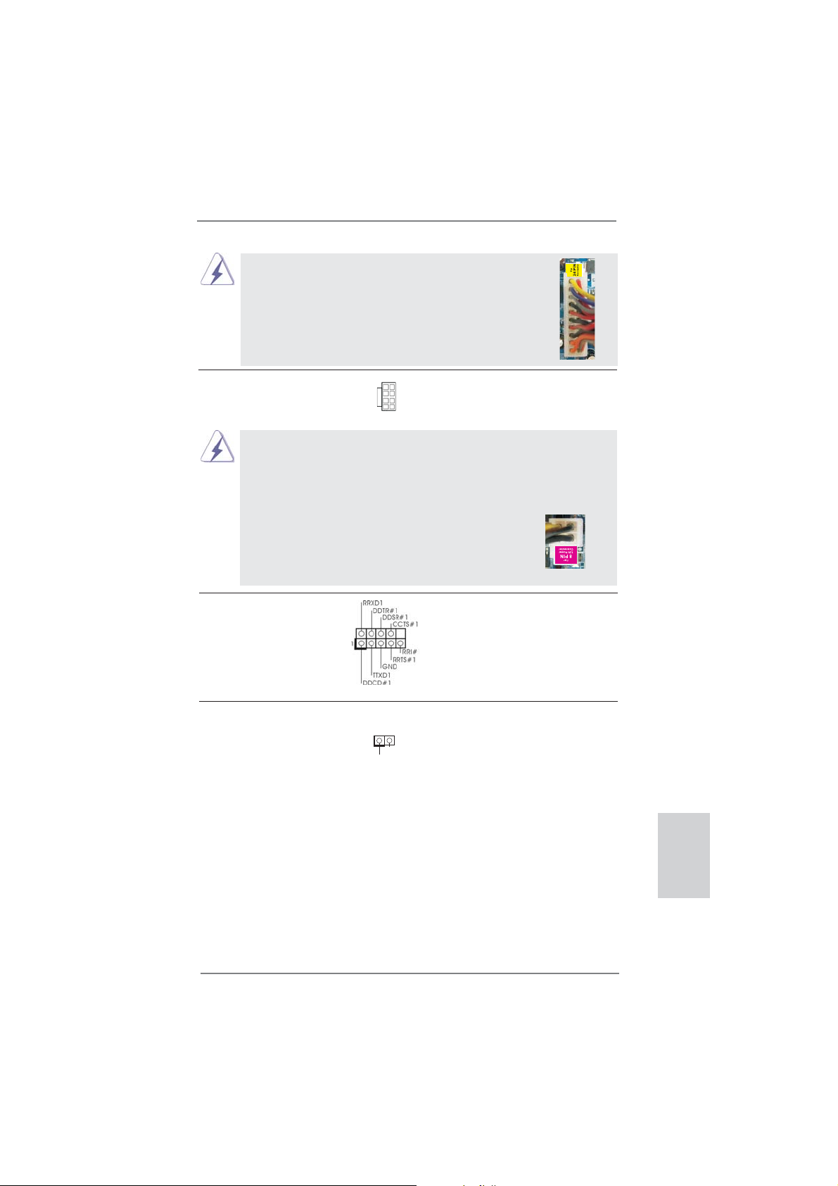
Obwohl dieses Motherboard einen 24-pol. ATX Stromanschluss bietet, kann es auch mit einem
modifi zierten traditionellen 20-pol. ATX-Netzteil
verwendet werden. Um ein 20-pol. ATX-Netzteil zu
verwenden, stecken Sie den Stecker mit Pin 1 und
Pin 13 ein.
Installation eines 20-pol. ATX-Netzteils
12
1
24
13
ATX 12V Anschluss Bitte schließen Sie an diesen
(8-pin ATX12V1)
(siehe S.2 - No. 1)
Anschluss die ATX 12V
Stromversorgung an.
5 1
8 4
Obwohl diese Hauptplatine 8-Pin ATX 12V Stromanschluss zur
Verfügung stellt, kann sie noch arbeiten, wenn Sie einen
traditionellen 4-Pin ATX 12V Energieversorgung adoptieren. Um die
4-Pin ATX Energieversorgung zu verwenden, stecken Sie bitte Ihre
Energieversorgung zusammen mit dem Pin 1 und Pin 5 ein.
5 1
Installation der 4-Pin ATX 12V Energieversorgung
8 4
COM-Anschluss-Header Dieser COM-Anschluss-
(9-pin COM1)
(siehe S.2 - No. 30)
Header wird verwendet, um
ein COM-Anschlussmodul zu
unterstützen.
HDMI_SPDIF-Anschluss Der HDMI_SPDIF-Anschluss
(2-pin HDMI_SPDIF1)
(siehe S.2 - No. 31)
VGA-Karte zur Verfügung und
stellt einen SPDIF-
Audioausgang für eine HDMI-
1
GND
SPDIFOUT
ermöglicht den Anschluss von
HDMI-Digitalgeräten wie
Fernsehgeräten, Projektoren,
LCD-Geräten an das System.
Bitte verbinden Sie den
HDMI_SPDIF-Anschluss der
HDMI-VGA-Karte mit diesem
Deutsch
Anschluss.
ASRock 970 Extreme3 Motherboard
41
Page 42

2. BIOS-Information
Das Flash Memory dieses Motherboards speichert das Setup-Utility. Drücken Sie
<F2> oder <Del> während des POST (Power-On-Self-Test) um ins Setup zu gelangen, ansonsten werden die Testroutinen weiter abgearbeitet. Wenn Sie ins Setup
gelangen wollen, nachdem der POST durchgeführt wurde, müssen Sie das System
über die Tastenkombination <Ctrl> + <Alt> + <Delete> oder den Reset-Knopf auf
der Gehäusevorderseite, neu starten. Natürlich können Sie einen Neustart auch
durchführen, indem Sie das System kurz ab- und danach wieder anschalten.
Das Setup-Programm ist für eine bequeme Bedienung entwickelt worden. Es ist ein
menügesteuertes Programm, in dem Sie durch unterschiedliche Untermenüs scrollen und die vorab festgelegten Optionen auswählen können. Für detaillierte Informationen zum BIOS-Setup, siehe bitte das Benutzerhandbuch (PDF Datei) auf der
Support CD.
3. Software Support CD information
Dieses Motherboard unterstützt eine Reiche von Microsoft® Windows® Betriebssystemen: 7 / 7 64-Bit / VistaTM / VistaTM 64-Bit / XP / XP 64-Bit. Die Ihrem Motherboard
beigefügte Support-CD enthält hilfreiche Software, Treiber und Hilfsprogramme, mit
denen Sie die Funktionen Ihres Motherboards verbessern können Legen Sie die
Support-CD zunächst in Ihr CD-ROM-Laufwerk ein. Der Willkommensbildschirm
mit den Installationsmenüs der CD wird automatisch aufgerufen, wenn Sie die
“Autorun”-Funktion Ihres Systems aktiviert haben.
Erscheint der Wilkommensbildschirm nicht, so “doppelklicken” Sie bitte auf das File
ASSETUP.EXE im BIN-Verzeichnis der Support-CD, um die Menüs aufzurufen.
Das Setup-Programm soll es Ihnen so leicht wie möglich machen. Es ist menügesteuert, d.h. Sie können in den verschiedenen Untermenüs Ihre Auswahl treffen und
die Programme werden dann automatisch installiert.
Deutsch
42
ASRock 970 Extreme3 Motherboard
Page 43
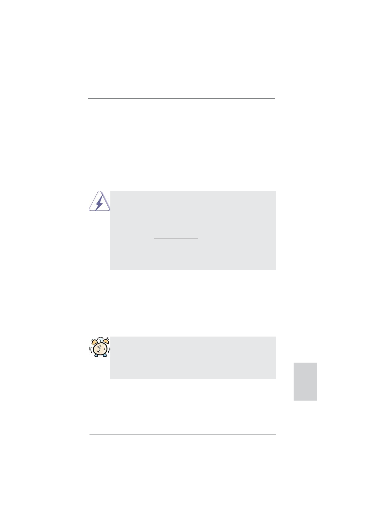
1. Introduction
Merci pour votre achat d’une carte mère ASRock 970 Extreme3, une carte mère
très fi able produite selon les critères de qualité rigoureux de ASRock. Elle offre des
performances excellentes et une conception robuste conformément à l’engagement
d’ASRock sur la qualité et la fi abilité au long terme.
Ce Guide d’installation rapide présente la carte mère et constitue un guide
d’installation pas à pas. Des informations plus détaillées concernant la carte
mère pourront être trouvées dans le manuel l’utilisateur qui se trouve sur le CD
d’assistance.
Les spécifi cations de la carte mère et le BIOS ayant pu être mis à
jour, le contenu de ce manuel est sujet à des changements sans
notifi cation. Au cas où n’importe qu’elle modifi cation intervenait sur ce
manuel, la version mise à jour serait disponible sur le site web
ASRock sans nouvel avis. Vous trouverez les listes de prise en
charge des cartes VGA et CPU également sur le site Web ASRock.
Site web ASRock, http://www.asrock.com
Si vous avez besoin de support technique en relation avec cette carte
mère, veuillez consulter notre site Web pour de plus amples
informations particulières au modèle que vous utilisez.
www.asrock.com/support/index.asp
1.1 Contenu du paquet
Carte mère ASRock 970 Extreme3
(Facteur de forme ATX: 12.0 pouces x 8.6 pouces, 30.5 cm x 21.8 cm)
Guide d’installation rapide ASRock 970 Extreme3
CD de soutien ASRock 970 Extreme3
Deux câbles de données de série ATA (SATA) (en option)
Un I/O Panel Shield
ASRock vous rappelle...
Pour bénéfi cier des meilleures performances sous Windows® 7 / 7 64 bits
TM
/ Vista
/ VistaTM 64 bits, il est recommandé de paramétrer l'option BIOS
dans Confi guration de stockage en mode AHCI. Pour plus de détails sur
l'installation BIOS, référez-vous au "Mode d'emploi" sur votre CD de support.
ASRock 970 Extreme3 Motherboard
Français
43
Page 44
Français
1.2 Spécifications
Format - Facteur de forme ATX:
12.0 pouces x 8.6 pouces, 30.5 cm x 21.8 cm
- Accessoires de Carte mère (condensateurs 100% polymère
conducteur de haute qualité fabriqué au Japon)
CPU - Prise en charge des processeurs sur socket AM3+
- Prise en charge des processeurs sur socket AM3:
Processeur Phenom
Athlon II X4 / X3 / X2 / Sempron d’AMD
- Prêt pour processeurs Huit-Core
- Supporte UCC (Unlock CPU Core) (voir ATTENTION 1)
- Conception V4 + 1 Power Phase
- Supporte les processeurs jusqu’à 140W
- Supporte la technologie Cool ‘n’ Quiet
- FSB 2400 MHz (4.8 GT/s)
- Prend en charge la technologie Untied Overclocking
(voir ATTENTION 2)
- Prise en charge de la technologie Hyper Transport 3.0
(HT 3.0)
Chipsets - Northbridge: AMD 970FX
- Southbridge: AMD SB950
Mémoire - Compatible avec la Technologie de Mémoire à Canal
Double (voir ATTENTION 3)
- 4 x slots DIMM DDR3
- Supporter DDR3 2100(OC)/1866(OC)/1800(OC)/1600(OC)
/1333/1066/800 non-ECC, sans amortissement mémoire
(voir ATTENTION 4)
- Capacité maxi de mémoire système: 32GB
(voir ATTENTION 5)
Slot d’extension - 2 x slots PCI Express 2.0 x16
(PCIE2: mode x16; PCIE4: mode x4)
- 2 x slot PCI Express 2.0 x1
- 2 x slots PCI
- Prend en charge AMD
Audio - 7,1 CH HD Audio avec protection de contenu
(Realtek ALC892 Audio Codec)
- Prise en charge de l’audio Premium Blu-ray
- Prend en charge THX TruStudioTM
LAN - PCIE x1 Gigabit LAN 10/100/1000 Mb/s
- Realtek RTL8111E
TM
II X6 / X4 / X3 / X2 (sauf 920 / 940) /
TM
d’AMD
TM
Quad CrossFireXTM et CrossFireXTM
44
ASRock 970 Extreme3 Motherboard
Page 45

- Supporte du Wake-On-LAN
- Prise en charge de la détection de câble LAN
- Prend en charge la norme Energy Effi cient Ethernet
(Ethernet à effi cacité énergétique) 802.3az
- Support de PXE
Panneau arrière I/O Panel
- 1 x port souris PS/2
- 1 x port clavier PS/2
- 1 x Port de sortie coaxial SPDIF
- 1 x Port de sortie optique SPDIF
- 4 x ports USB 2.0 par défaut
- 2 x ports USB 3.0 par défaut
- 1 x Connecteur eSATA3
- 1 x port LAN RJ-45 avec LED (ACT/LED CLIGNOTANTE et
LED VITESSE)
- Prise HD Audio: Haut-parleur latéral / Haut-parleur arrière /
Central /Basses / Entrée Ligne / Haut-parleur frontal /
Microphone (voir ATTENTION 6)
SATA 3 - 5 x connecteurs 6,0 Gb/s SATA3, prise en charge des
fonctions RAID (RAID 0, RAID 1, RAID 5 et RAID 10), NCQ,
AHCI et « Connexion à chaud »
USB 3.0 - 2 x ports USB3.0 à l’arrière par Etron EJ168A,
prennent en charge USB 1.0/2.0/3.0 jusqu’à 5 Gb/s
Connecteurs - 5 x connecteurs SATA3, prennent en charge un taux de
transfert de données pouvant aller jusqu’à 6.0Go/s
- 1 x En-tête du module infrarouge
- 1 x
- 1 x En-tête de port COM
- 1 x Connecteur HDMI_SPDIF
- 1 x LED di accensione
- Connecteur pour ventilateur de CPU/Châssis/Ventilateur
- br. 24 connecteur d’alimentation ATX
- br. 8 connecteur d’alimentation 12V ATX
- Connecteur audio panneau avant
- 3 x En-tête USB 2.0 (prendre en charge 6 ports USB 2.0
supplémentaires)
BIOS - 32Mb AMI UEFI Legal BIOS avec support GUI
- Support du “Plug and Play”
- Compatible pour événements de réveil ACPI 1.1
- Gestion jumperless
- Support SMBIOS 2.3.1
- CPU, VCCM, NB, SB Tension Multi-ajustement
Barrette pour module à infrarouges grand public
ASRock 970 Extreme3 Motherboard
Français
45
Page 46

Français
CD d’assistance - Pilotes, utilitaires, logiciel anti-virus (Version d’essai),
CyberLink MediaEspresso 6.5 Trial, Utilitaire AMD
OverDriveTM, AMD Fusion, AMD Fusion Media Explorer,
Suite logicielle ASRock (suite CyberLink DVD - OEM et
version d’évaluation; Suite multimédia ASRock MAGIX OEM)
Caractéristique - Utilitaire ASRock Extreme Tuning (AXTU)
Caractéristique (voir ATTENTION 7)
unique - ASRock l'Instant Boot
- ASRock Instant Flash (voir ATTENTION 8)
- Chargeur ASRock APP (voir ATTENTION 9)
- ASRock SmartView (voir ATTENTION 10)
- ASRock XFast USB (voir ATTENTION 11)
- ASRock XFast LAN (voir ATTENTION 12)
- Technologie Lecture Marche/Arrêt ASRock
(voir ATTENTION 13)
- L’accélérateur hybride:
- Contrôle direct de la fréquence CPU
(voir ATTENTION 14)
- ASRock U-COP (voir ATTENTION 15)
- Garde d’échec au démarrage (B.F.G.)
- Turbo UCC
Surveillance - Détection de la température de l’UC
système - Mesure de température de la carte mère
- Tachéomètre ventilateur CPU/Châssis/Ventilateur
- Ventilateur silencieux pour unité centrale/châssis
- Commande de ventilateur CPU/boîtier à plusieurs vitesses
- Monitoring de la tension: +12V, +5V, +3.3V, Vcore
OS - Microsoft
®
Windows® 7 / 7 64-bit / Vista
TM
/ VistaTM 64-bit /
XP / XP 64-bit
Certifi cations - FCC, CE, WHQL
- Prêt pour ErP/EuP (alimentation Prêt pour ErP/EuP requise)
(voir ATTENTION 16)
* Pour de plus amples informations sur les produits, s’il vous plaît visitez notre site web:
http://www.asrock.com
46
ASRock 970 Extreme3 Motherboard
Page 47

ATTENTION
Il est important que vous réalisiez qu’il y a un certain risque à effectuer l’overclocking, y
compris ajuster les réglages du BIOS, appliquer la technologie Untied Overclocking, ou
utiliser des outils de tiers pour l’overclocking. L’overclocking peut affecter la stabilité de
votre système, ou même causer des dommages aux composants et dispositifs de votre
système. Si vous le faites, c’est à vos frais et vos propres risques. Nous ne sommes
pas responsables des dommages possibles causés par l’overclocking.
ATTENTION!
1. La fonction ASRock UCC (Unlock CPU Core : Déverrouillage du coeur
du processeur) permet de simplifi er l’activation des processeurs AMD.
Il vous suffi t de sélectionner dans le UEFI l’option « Unlock CPU Core »
(Déverrouillage du coeur du processeur), et vous pouvez déverrouiller le
coeur du processeur pour profi ter instantanément de performances ren-
forcées. Lorsque la fonction UCC est activée, le processeur à double ou
à triple coeur sera renforcée de façon à fonctionner comme processeur à
quatre coeurs, et pour certains processeurs, notamment les processeurs
quad-core, la taille du cache L3 sera aussi augmentée pour passer à 6
Mo, ce qui signifi e que vous pourrez améliorer les performances du pro-
cesseur à plus faible coût. Veuillez noter que la fonction UCC est prise en
charge uniquement avec les processeurs AM3/AM3+, et en outre, tous
les processeurs AM3/AM3+ ne prennent pas cette fonction en charge car
certains coeurs cachés de processeurs risquent de dysfonctionner.
2. Cette carte mère prend en charge la technologie Untied Overclocking.
Veuillez lire “La technologie de surcadençage à la volée” à la page 27
pour plus d’informations.
3. Cette carte mère supporte la Technologie de Mémoire à Canal Double.
Avant d’intégrer la Technologie de Mémoire à Canal Double, assurezvous de bien lire le guide d’installation des modules mémoire en page 14
pour réaliser une installation correcte.
4. La prise en charge de fréquences de mémoire de
2100/1866/1800/1600MHz dépend du CPU AM3/AM3+ que vous
choisissez. Si vous choisissez des barrettes de mémoire DDR3
2100/1866/1800/1600 sur cette carte mère, veuillez vous référer à la
liste des mémoires prises en charge sur notre site Web pour connaître
barrettes de mémoire compatibles. DDR3 1866 avec mode Non OC est
supporté par AM3+ CPU.
Site Web ASRock http://www.asrock.com
5. Du fait des limites du système d’exploitation, la taille mémoire réelle
réservée au système pourra être inférieure à 4 Go sous Windows
VistaTM / XP. Avec Windows® OS avec CPU 64 bits, il n’y a pas ce genre
de limitation.
6. Pour l’entrée microphone, cette carte mère supporte les deux modes
stéréo et mono. Pour la sortie audio, cette carte mère supporte les
modes 2-canaux, 4-canaux, 6-canaux et 8-canaux. Veuillez vous référer
au tableau en page 3 pour effectuer la bonne connexion.
®
7 /
ASRock 970 Extreme3 Motherboard
Français
47
Page 48

Français
7. ASRock Extreme Tuning Utility (AXTU) est un utilitaire tout-en-un qui
permet de régler précisément différentes fonctions du système, via une
interface facile à utiliser, incluant Moniteur de périphériques, Contrôle du
ventilateur, Overclocking, OC DNA et IES. Dans Moniteur de périphériques, il affi che les valeurs principales de votre système.
Dans Contrôle du ventilateur, il affi che la vitesse du ventilateur et la
température, que vous pouvez ajuster. Dans Overclocking, vous pouvez
overclocker la fréquence du CPU pour améliorer les performances du
système. Dans OC DNA, vous pouvez enregistrer vos réglages OC dans
un profi l et les partager avec vos amis. Vos amis pourront alors installer
le profi l OC sur leur système pour utiliser les mêmes réglages OC.
Dans IES (Intelligent Energy Saver – Fonction intelligente d’économie
d’énergie), le contrôleur de la tension peut réduire le nombre de phases
de sortie pour améliorer le fonctionnement lorsque les cores du CPU
ne sont pas utilisées, sans diminuer les performances de l’ordinateur.
Veuillez visiter notre site Web pour plus d’informations sur l’utilisation des
fonctions de l’utilitaire ASRock Extreme Tuning Utility (AXTU). Site Web
de ASRock : http://www.asrock.com
8. O ASRock Instant Flash é um utilitário de fl ash do BIOS incorporado na
memória Flash ROM. Esta prática ferramenta de actualização do BIOS
permite-lhe actualizar o BIOS do sistema sem necessitar de entrar nos
sistemas operativos, como o MS-DOS ou o Windows
utilitário, poderá premir a tecla <F6> durante o teste de arranque POST
ou premir a tecla <F2> para exibir o menu de confi guração do BIOS para
aceder ao ASRock Instant Flash. Execute esta ferramenta para guardar
o novo fi cheiro de BIOS numa unidade fl ash USB, numa disquete ou
num disco rígido, em seguida, poderá actualizar o BIOS com apenas
alguns cliques sem ter de utilizar outra disquete ou outro complicado
utilitário de fl ash. Note que a unidade fl ash USB ou a unidade de disco
rígido devem utilizar o sistema de fi cheiros FAT32/16/12.
9. Si vous désirez un moyen plus rapide et moins contraignant de recharger
vos appareils Apple tels que iPhone/iPod/iPad Touch, ASRock a préparé
pour vous la solution idéale - le chargeur ASRock APP. Il suffi t d’installer
le pilote du chargeur APP, et vous pourrez recharger rapidement votre
iPhone à partir de votre ordinateur, jusqu’à 40% plus vite qu’avant. Le
chargeur ASRock APP vous permet de charger rapidement et simultanément plusieurs appareils Apple, et le chargement continu est même
pris en charge lorsque le PC passe en mode Veille (S1), Suspension à
la RAM (S3), hibernation (S4) ou hors tension (S5). Lorsque le pilote du
chargeur APP est installé, vous découvrez un mode de mise en charge
tout à fait inédit.
Site web ASRock : http://www.asrock.com/Feature/AppCharger/index.asp
10. SmartView, nouvelle fonction pour les navigateurs Internet, est une page
de démarrage intelligente pour IE qui combine vos sites web les plus visités, votre historique, vos amis Facebook et vos fi ls d’actualité en temps
réel, le tout sous forme d’affi chage évolué, pour une expérience Internet
plus personnelle. Les cartes mères ASRock sont équipées de l’utilitaire
®
. Com este
48
ASRock 970 Extreme3 Motherboard
Page 49

SmartView qui vous aide à garder le contact avec vos proches à tout mo-
ment. Pour utiliser la fonction SmartView, veuillez vous assurer que votre
système d’exploitation est Windows® 7 / 7 64 bits / VistaTM ou VistaTM 64
bits, et que la version de votre navigateur est IE8.
Site web ASRock : http://www.asrock.com/Feature/SmartView/index.asp
11. ASRock XFast USB permet d’améliorer les performances de votre périphérique de stockage USB. Les performances réelles dépendent des
propriétés du périphérique.
12. ASRock XFast LAN fournit un accès Internet plus rapide, avec les avantages suivants. Priorisation d’application LAN : Vous pouvez confi gurer
votre priorité d’application idéalement et/ou ajouter des nouveaux programmes. Latence plus basse dans les jeux : Après avoir réglé la priorité
de jeux en ligne plus haute, cela peut réduire la latence dans les jeux.
Forme du trafi c : Vous pouvez regarder des vidéos HD YouTube et té-
lécharger simultanément des fi chiers. Analyse en temps réel de vos don-
nées : Avec la fenêtre d’état, vous pouvez facilement reconnaître les fl ux
de données que vous êtes en train de transférer.
13. La Technologie Lecture Marche/Arrêt ASRock permet aux utilisateurs
d’expériencer l’audio incroyable à partir d’appareils audio portables
comme un lecteur MP3 ou un téléphone portable, sur votre PC, même
lorsque le PC est éteint (ou en mode ACPI S5)! Cette carte mère fournie
aussi un câble audio 3,5mm gratuit (optionnel) qui facilite beaucoup dans
les environnements informatiques.
14. Même si cette carte mère offre un contrôle sans souci, il n’est pas
recommandé d’y appliquer un over clocking. Les fréquences autres que
les fréquences de bus d’UC recommandées risquent de déstabiliser le
système ou d’endommager l’UC.
15. Lorsqu’une surchauffe du CPU est détectée, le système s’arrête
automatiquement. Avant de redémarrer le système, veuillez vérifi er que
le ventilateur d’UC sur la carte mère fonctionne correctement et
débranchez le cordon d’alimentation, puis rebranchez-le. Pour améliorer
la dissipation de la chaleur, n’oubliez pas de mettre de la pâte thermique
entre le CPU le dissipateur lors de l’installation du PC.
16. EuP, qui signifi e Energy Using Product (Produit Utilisant de l’Energie),
est une disposition établie par l’Union Européenne pour défi nir la con-
sommation de courant pour le système entier. Conformément à la norme
EuP, le courant CA total du système entier doit être inférieur à 1 W en
mode d’arrêt. Pour être conforme à la norme EuP, une carte mère EuP
et une alimentation EuP sont requises. Selon les suggestions d’Intel’,
l’alimentation électrique EuP doit correspondre à la norme, qui est que
l’effi cacité électrique de 5v en mode de veille doit être supérieure à 50%
pour 100 mA de consommation de courant. Pour choisir une alimentation
électrique conforme à la norme EuP, nous vous recommandons de consulter votre fournisseur de courant pour plus de détails.
Français
ASRock 970 Extreme3 Motherboard
49
Page 50

1.3 Réglage des cavaliers
L’illustration explique le réglage des cavaliers. Quand un capuchon est placé sur les
broches, le cavalier est « FERME ». Si aucun capuchon ne relie les broches,le cavalier est « OUVERT ». L’illustration montre un
cavalier à 3 broches dont les broches 1 et 2
sont « FERMEES » quand le capuchon est
placé sur ces 2 broches.
Le cavalier Description
Effacer la CMOS
(CLRCMOS1)
(voir p.2 fi g. 21)
Remarque :
Paramètres
par défaut
CLRCMOS1 vous permet d’effacer les données du CMOS. Pour effacer
et réinitialiser les paramètres du système à la confi guration originale,
veuillez éteindre l’ordinateur et débrancher le cordon d’alimentation de
la prise de courant. Après 15 secondes, utilisez un couvercle de jumper
pour court-circuiter les broches pin2 et pin3 de CLRCMOS1 pendant
secondes. Veuillez cependant ne pas effacer le CMOS immédiatement
a
près avoir mis à jour le BIOS. Si vous avez besoin d’effacer le CMOS
après avoir mis à jour le BIOS, vous devez allumer en premier le
système, puis l’éteindre avant de continuer avec l’opération d’effacement
du CMOS. Veuillez noter que le mot de passe, la date, l’heure, le profi l
par défaut de l’utilisateur, 1394 GUID et l’adresse MAC seront effacés
seulement si la batterie du CMOS est enlevée.
Effacer la
CMOS
5
Français
50
ASRock 970 Extreme3 Motherboard
Page 51
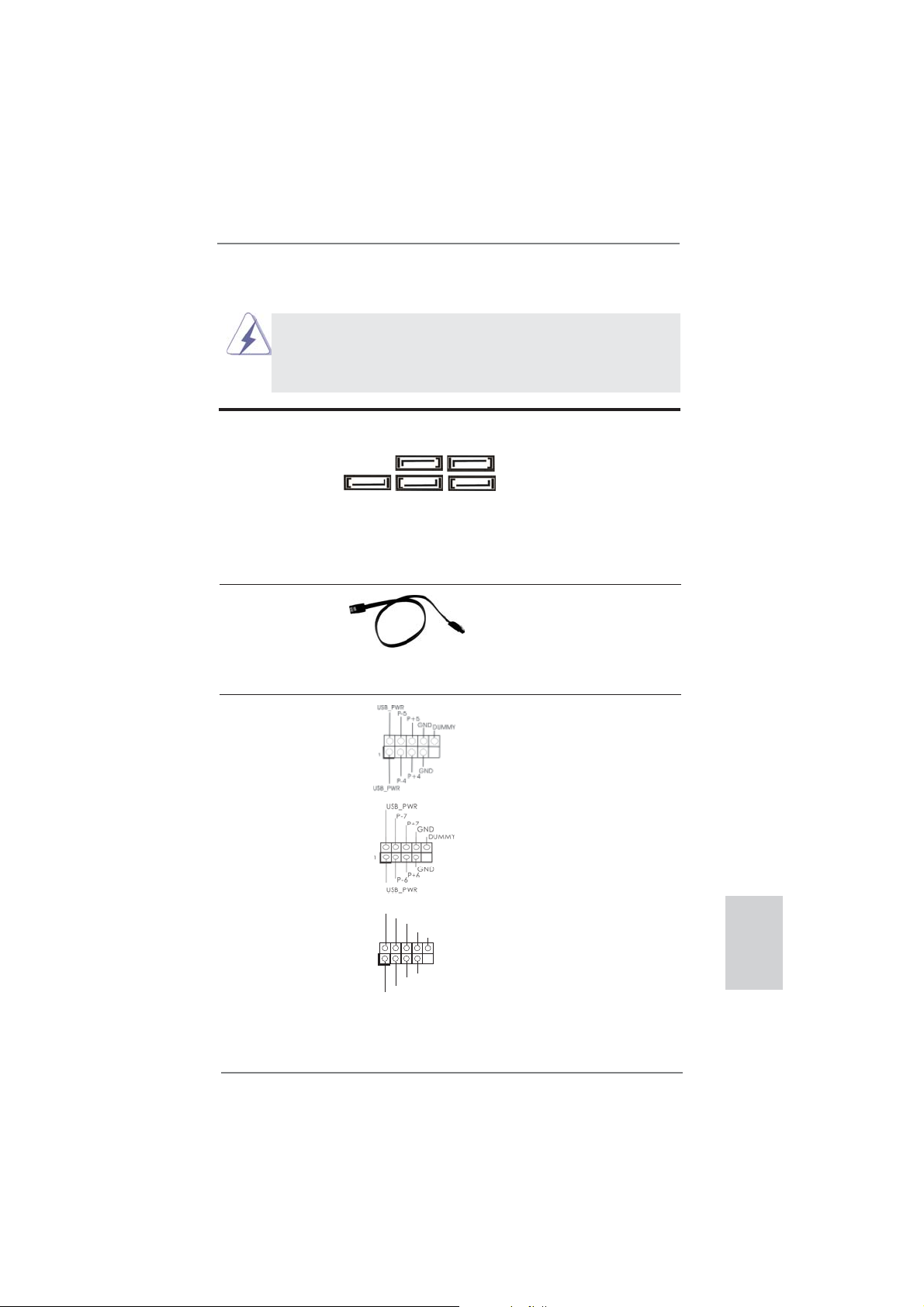
1.4 En-têtes et Connecteurs sur Carte
Les en-têtes et connecteurs sur carte NE SONT PAS des cavaliers.
NE PAS placer les capuchons de cavalier sur ces en-têtes et connecteurs. Le fait de placer les capuchons de cavalier sur les en-têtes
et connecteurs causera à la carte mère des dommages irréversibles!
Connecteurs Série ATA3 Ces cinq connecteurs Série
(SATA3_1: voir p.2 No. 17)
(SATA3_2: voir p.2 No. 18)
(SATA3_3 voir p.2 No. 16)
(SATA3_4 voir p.2 No. 19)
(SATA3_5 voir p.2 No. 20)
transferts de données pouvant
aller jusqu’à 6,0 Gb/s.
Câble de données Toute cote du cable de data
Série ATA (SATA) SATA peut etre connecte au
(en option)
disque dur SATA / SATAII /
SATA3 ou au connecteur SATA3
sur la carte mere.
En-tête USB 2.0 A côté des quatre ports USB
(USB_4_5 br.9)
(voir p.2 No. 26)
2.0 par défaut sur le panneau
2.0 sur cette carte mère.
Chaque embase USB 2.0 peut
prendre en charge 2 ports USB
(USB_6_7 br.9)
(voir p.2 No. 27)
2.0.
ATA3 (SATA3) prennent en
SATA3_3 SATA3_1
charge les câbles SATA pour
les périphériques de stockage
internes. L’interface SATA3
SATA3_5 SATA3_4 SATA3_2
actuelle permet des taux
E/S, il y a troi embases USB
(USB_8_9 br.9)
(voir p.2 No. 28)
USB_PWR
P-9
P+9
GND
DUMMY
1
GND
P+8
P-8
USB_PWR
ASRock 970 Extreme3 Motherboard
Français
51
Page 52

En-tête du module infrarouge Cet en-tête supporte un module
(IR1 br.5)
infrarouge optionnel de
(voir p.2 No. 29)
transfert et de réception sans
fi l.
IRTX
+5VSB
DUMMY
1
GND
IRRX
Barrette pour module à infrarouges grand public Cette barrette peut être utilisée
(CIR1 br.4)
(voir p.2 No. 25)
pour connecter des récepteur
1
ATX+5VSB
IRRX
IRTX
GND
1
GND
PRESENCE#
MIC2_R
MIC2_L
MIC_RET
J_SENSE
OUT2_R
OUT_RET
OUT2_L
Connecteur audio panneau C’est une interface pour
(HD_AUDIO1 br. 9)
(voir p.2 No. 32)
un câble avant audio en façade
qui permet le branchement et
le contrôle commodes de
périphériques audio.
1. L’audio à haute défi nition (HDA) prend en charge la détection de fi che,
mais le fi l de panneau sur le châssis doit prendre en charge le HDA pour
fonctionner correctement. Veuillez suivre les instructions dans notre
manuel et le manuel de châssis afi n installer votre système.
2. Si vous utilisez le panneau audio AC’97, installez-le sur l’adaptateur audio
du panneau avant conformément à la procédure ci-dessous :
A. Connectez Mic_IN (MIC) à MIC2_L.
B. Connectez Audio_R (RIN) à OUT2_R et Audio_L (LIN) à OUT2_L.
C. Connectez Ground (GND) à Ground (GND).
D. MIC_RET et OUT_RET sont réservés au panneau audio HD. Vous
n’avez pas besoin de les connecter pour le panneau audio AC’97.
E. Pour activer le micro avant.
Pour les systèmes d’exploitation Windows
®
XP / XP 64 bits :
Sélectionnez “Mixer”. Sélectionnez “Recorder” (Enregistreur). Puis cliquez
sur “FrontMic” (Micro avant).
Pour les systèmes d’exploitation Windows® 7 / 7 64 bits / VistaTM / VistaTM
64 bits :
Allez sur l’onglet “FrontMic” (Micro avant) sur le Panneau de contrôle
Realtek. Ajustez “Recording Volume” (Volume d’enregistrement).
Français
En-tête du panneau système Cet en-tête permet d’utiliser
(PANEL1 br.9)
(voir p.2 No. 23)
plusieurs fonctions du
panneau système frontal.
52
ASRock 970 Extreme3 Motherboard
Page 53

Connectez l’interrupteur d’alimentation, l’interrupteur de réinitialisation et
l’indicateur d’état du système du châssis sur cette barrette en respectant
l’affectation des broches décrite ci-dessous. Faites attention aux broches
positives et négatives avant de connecter les câbles.
PWRBTN (Interrupteur d’alimentation):
Connectez ici le connecteur d’alimentation sur le panneau avant du
châssis. Vous pouvez confi gurer la façon de mettre votre système hors
tension avec l’interrupteur d’alimentation.
RESET (Interrupteur de réinitialisation):
Connectez ici le connecteur de réinitialisation sur le panneau avant du
châssis. Appuyez sur l’interrupteur de réinitialisation pour redémarrer
l’ordinateur s’il se bloque ou s’il n’arrive pas à redémarrer normalement.
PLED (DEL alimentation système):
Connectez ici l’indicateur d’état de l’alimentation sur le panneau avant
du châssis. Ce voyant DEL est allumé lorsque le système est en
marche. Le voyant DEL clignote lorsque le système est en mode veille
S1. Le voyant DEL est éteint lorsque le système est en mode veille S3/
S4 ou lorsqu’il est éteint (S5).
HDLED (DEL activité du disque dur):
Connectez ici le voyant DEL d’activité du disque dur sur le panneau
avant du châssis. Ce voyant DEL est allumé lorsque le disque dur est en
train de lire ou d’écrire des données.
Le design du panneau avant peut varier en fonction du châssis. Un
module de panneau avant consiste principalement en : interrupteur
d’alimentation, interrupteur de réinitialisation, voyant DEL d’alimentation,
voyant DEL d’activité du disque dur, haut-parleur, etc. Lorsque vous
connectez le panneau avant de votre châssis sur cette barrette, vérifi ez
bien à faire correspondre les fi ls et les broches.
En-tête du haut-parleur Veuillez connecter le
de châssis haut-parleur de châssis sur
(SPEAKER1 br. 4)
(voir p.2 No. 24)
LED di accensione Collegare il LED di accensione
(3-pin PLED1)
(vedi p.2 Nr. 22)
cet en-tête.
1
chassi per indicare lo stato di
alimentazione del sistema. Il
PLED+
PLED+
PLED-
LED è acceso quando il sistema
è in funzione. Il LED continua a
lampeggiare in stato S1. Il LED
è spento in stato S3/S4 o S5
(spegnimento).
ASRock 970 Extreme3 Motherboard
Français
53
Page 54

Connecteur pour châssis et ventilateur
(CHA_FAN1 br. 4)
(voir p.2 No. 12)
(CHA_FAN2 br. 3)
(voir p.2 No. 15)
(CHA_FAN3 br. 3)
(voir p.2 No. 2)
GND
+12V
CHA_FAN_SPEED
FAN_SPEED_CONTROL
GND
+12V
CHA_FAN_SPEED
Branchez les câbles du
ventilateur aux connecteurs pour
ventilateur et faites correspondre
le fi l noir à la broche de terre. La
vitesse des ventilateurs CHA_
FAN1/2/3 peut être réglée avec
UEFI ou AXTU.
Français
(PWR_FAN1 br. 3)
(voir p.2 No. 10)
Connecteur du ventilateur Veuillez connecter le câble de
de l’UC ventilateur d’UC sur ce
(CPU_FAN1 br. 4)
(voir p.2 No. 6)
connecteur et brancher le fi l
noir sur la broche de terre.
GND
+12V
PWR_FAN_SPEED
FAN_SPEED_CONTROL
CPU_FAN_SPEED
+12V
GND
1 2 3 4
Bien que cette carte mère offre un support de (Ventilateur silencieux
ventilateur de CPU à 4 broches , le ventilateur de CPU à 3 broches peut
bien fonctionner même sans la fonction de commande de vitesse du
ventilateur. Si vous prévoyez de connecter le ventilateur de CPU à 3
broches au connecteur du ventilateur de CPU sur cette carte mère,
veuillez le connecter aux broches 1-3.
Installation de ventilateur à 3 broches
Broches 1-3 connectées
(CPU_FAN2 br. 3)
(voir p.2 No. 5)
En-tête d’alimentation ATX Veuillez connecter l’unité
(ATXPWR1 br. 24)
(voir p.2 No. 9)
GND
+12V
CPU_FAN_SPEED
12 124
d’alimentation ATX sur cet en-
tête.
13
Bien que cette carte mère fournisse un connecteur de
courant ATX 24 broches, elle peut encore fonctionner
si vous adopter une alimentation traditionnelle ATX 20
broches. Pour utiliser une alimentation ATX 20 broches,
branchez à l’alimentation électrique ainsi qu’aux
broches 1 et 13.
20-Installation de l’alimentation électrique ATX
54
ASRock 970 Extreme3 Motherboard
12
1
24
13
Page 55
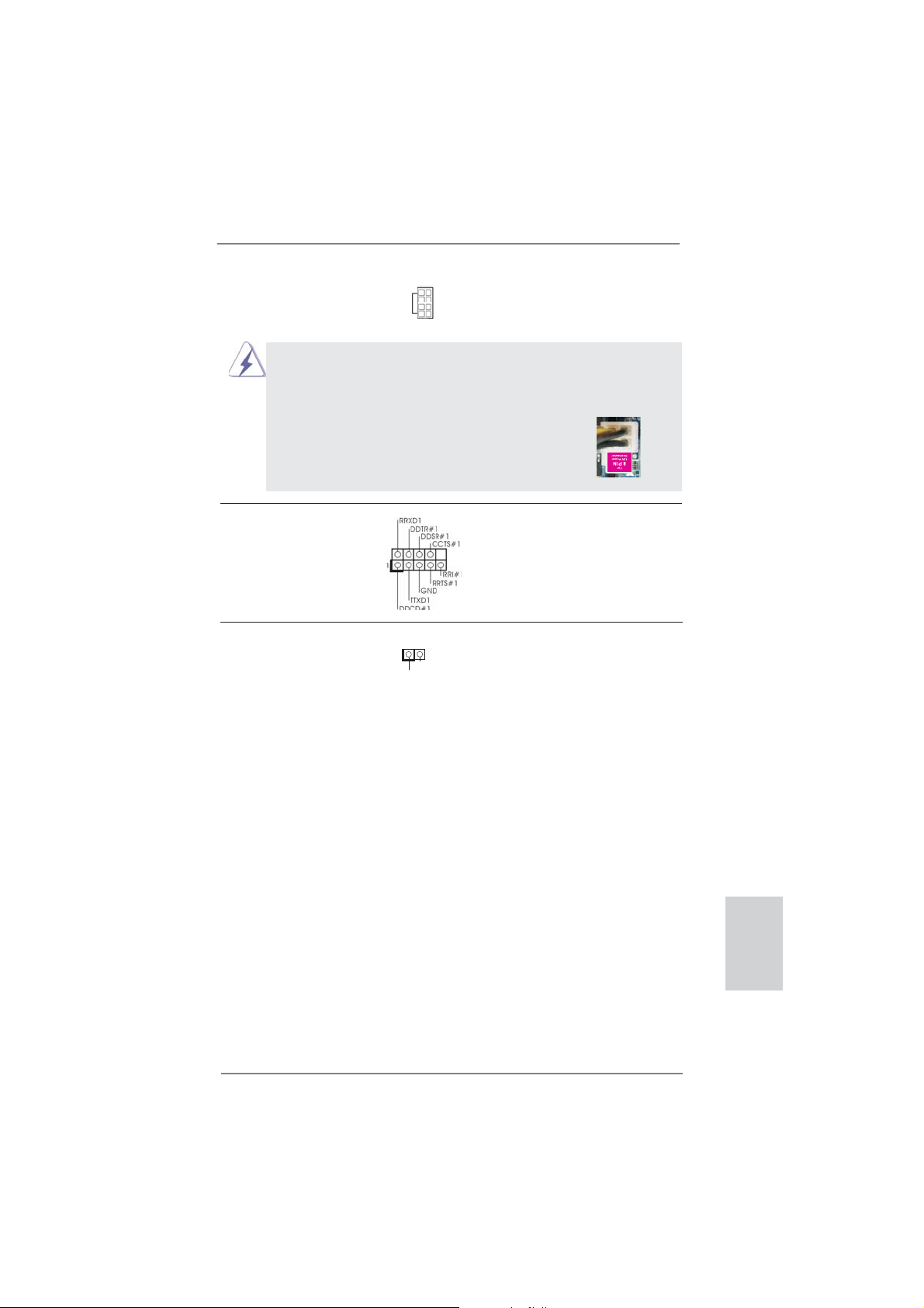
Connecteur ATX 12V Veuillez connecter une unité
(ATX12V1 br.8)
(voir p.2 No. 1)
d’alimentation électrique ATX
12V sur ce connecteur.
5 1
8 4
Bien que cette carte mère possède 8 broches connecteur d’alimentation
ATX 12V, il peut toujours travailler si vous adoptez une approche
traditionnelle à 4 broches ATX 12V alimentation. Pour utiliser
l’alimentation des 4 broches ATX, branchez votre alimentation
avec la broche 1 et la broche 5.
5 1
4-Installation d’alimentation à 4 broches ATX 12V
8 4
En-tête de port COM Cette en-tête de port COM est
(COM1 br.9)
(voir p.2 No. 30)
utilisée pour prendre en charge
un module de port COM.
Connecteur HDMI_SPDIF Connecteur HDMI_SPDIF,
(HDMI_SPDIF1 2-pin)
(voir p.2 No. 31)
SPDIF vers la carte VGA HDMI,
fournissant une sortie audio
1
GND
SPDIFOUT
et permettant au système
de se connecter au un
téléviseur numérique HDMI /un
projecteur / un périphérique
LCD. Veuillez brancher le
connecteur HDMI_SPDIF de la
carte VGA HDMI sur ce
connecteur.
ASRock 970 Extreme3 Motherboard
Français
55
Page 56

2. Informations sur le BIOS
La puce Flash Memory sur la carte mère stocke le Setup du BIOS. Lorsque vous
démarrez l’ordinateur, veuillez presser <F2> ou <Del> pendant le POST (Power-OnSelf-Test) pour entrer dans le BIOS; sinon, le POST continue ses tests de routine. Si
vous désirez entrer dans le BIOS après le POST, veuillez redémarrer le système en
pressant <Ctl> + <Alt> + <Suppr>, ou en pressant le bouton de reset sur le boîtier
du système. Vous pouvez également redémarrer en éteignant le système et en le
rallumant. L’utilitaire d’installation du BIOS est conçu pour être convivial. C’est un
programme piloté par menu, qui vous permet de faire défi ler par ses divers sous-
menus et de choisir parmi les choix prédéterminés. Pour des informations détaillées
sur le BIOS, veuillez consulter le Guide de l’utilisateur (fi chier PDF) dans le CD
technique.
3. Informations sur le CD de support
Cette carte mère supporte divers systèmes d’exploitation Microsoft® Windows®:
7 / 7 64 bits / VistaTM / Vista
cette carte mère contient les pilotes et les utilitaires nécessaires pour améliorer les
fonctions de la carte mère. Pour utiliser le CD technique, insérez-le dans le lecteur
de CD-ROM. Le Menu principal s’affi che automatiquement si “AUTORUN” est activé
dans votre ordinateur. Si le Menu principal n’apparaît pas automatiquement, localisez dans le CD technique le fi chier “ASSETUP.EXE” dans le dossier BIN et double-
cliquez dessus pour affi cher les menus.
TM
64 bits / XP / XP 64 bits. Le CD technique livré avec
Français
56
ASRock 970 Extreme3 Motherboard
Page 57

1. Introduzione
Grazie per aver scelto una scheda madre ASRock 970 Extreme3, una scheda
madre affi dabile prodotta secondo i severi criteri di qualità ASRock. Le prestazioni
eccellenti e il design robusto si conformano all’impegno di ASRock nella ricerca
della qualità e della resistenza.
Questa Guida Rapida all’Installazione contiene l’introduzione alla motherboard e la
guida passo-passo all’installazione. Informazioni più dettagliate sulla motherboard si
possono trovare nel manuale per l’utente presente nel CD di supporto.
Le specifi che della scheda madre e il software del BIOS possono
essere aggiornati, pertanto il contenuto di questo manuale può subire
variazioni senza preavviso. Nel caso in cui questo manuale sia
modifi cato, la versione aggiornata sarà disponibile sul sito di ASRock
senza altro avviso. Sul sito ASRock si possono anche trovare le più
recenti schede VGA e gli elenchi di CPU supportate.
ASRock website http://www.asrock.com
Se si necessita dell’assistenza tecnica per questa scheda madre,
visitare il nostro sito per informazioni specifi che sul modello che si
sta usando.
www.asrock.com/support/index.asp
1.1 Contenuto della confezione
Scheda madre ASRock 970 Extreme3
(ATX Form Factor: 12.0-in x 8.6-in, 30.5 cm x 21.8 cm)
Guida di installazione rapida ASRock 970 Extreme3
CD di supporto ASRock 970 Extreme3
Due cavi dati Serial ATA (SATA) (opzionali)
Un I/O Shield
ASRock vi ricorda...
Per ottenere migliori prestazioni in Windows® 7 / 7 64-bit / Vista
64-bit, si consiglia di impostare l'opzione BIOS in Storage Confi guration
(Confi gurazione di archiviazione) sulla modalità AHCI. Per l'impostazione
BIOS, fare riferimento a “User Manual” (Manuale dell'utente) nel CD di
supporto per dettagli.
TM
/ VistaTM
ASRock 970 Extreme3 Motherboard
Italiano
57
Page 58

Italiano
1.2 Specifiche
Piattaforma - ATX Form Factor: 12.0-in x 8.6-in, 30.5 cm x 21.8 cm
- Design condensatore compatto (condensatori a conduttore in
polimero di alta qualità realizzati al 100% in Giappone)
Processore - Supporto di processori Socket AM3+
- Supporto di processori Socket AM3: AMD Phenom
/ X3 / X2 (fatta eccezione per 920 / 940) / Athlon II X4 / X3 / X2
/ Sempron
- CPU Otto-Core Ready
- Supporto UCC (Unlock CPU Core) (vedi ATTENZIONE 1)
- Struttura di fase con alimentazione V4 + 1
- Supporta CPU fi no a 140 W
- Supporto tecnologia AMD Cool ‘n’ Quiet
TM
- FSB 2400 MHz (4.8 GT/s)
- Supporta la tecnologia overclocking “slegata”
(vedi ATTENZIONE 2)
- Supporta la tecnologia Hyper-Transport 3.0 (HT 3.0)
Chipset - Northbridge: AMD 970
- Southbridge: AMD SB950
Memoria - Supporto tecnologia Dual Channel Memory
(vedi ATTENZIONE 3)
- 4 x slot DDR3 DIMM
- Supporto DDR3 2100(OC)/1866(OC)/1800(OC)/1600(OC)/
1333/1066/800 non-ECC, momoria senza buffer (vedi
ATTENZIONE 4)
- Capacità massima della memoria di sistema: 32GB
(vedi ATTENZIONE 5)
Slot di - 2 x alloggiamenti PCI Express 2.0 x16
espansione (PCIE2: modalità x16; PCIE4: modalità x4)
- 2 x slot PCI Express 2.0 x1
- 2 x slot PCI
- Supporto di AMD
TM
Quad CrossFireXTM e CrossFireXTM
Audio - 7.1 CH HD Audio con protezioni contenuti
(Realtek ALC892 Audio Codec)
- Supporto audio Blu-ray Premium
- Supporto THX TruStudio
TM
LAN - PCIE x1 Gigabit LAN 10/100/1000 Mb/s
- Realtek RTL8111E
- Supporta Wake-On-LAN
- Supporta il rilevamento cavo LAN
TM
II X6 / X4
58
ASRock 970 Extreme3 Motherboard
Page 59
- Supporto di Energy Effi cient Ethernet 802.3az
- Supporta PXE
Pannello I/O Panel
posteriore - 1 x porta PS/2 per mouse
I/O - 1 x porta PS/2 per tastiera
- 1 x Porta coassiale SPDIF Out
- 1 x Porta ottica SPDIF Out
- 4 x porte USB 2.0 già integrate
- 2 x porte USB 3.0 già integrate
- 1 x Connettore eSATA3
- 1 x porte LAN RJ-45 con LED (LED azione/collegamento e
LED velocità)
- Connettore HD Audio: cassa laterale / cassa posteriore /
cassa centrale / bassi / ingresso linea / cassa frontale /
microfono (vedi ATTENZIONE 6)
SATA3 - 5 x connettori SATA3 6,0 Gb/s, supporto di RAID (RAID 0,
RAID 1, RAID 5 e RAID 10) e delle funzioni NCQ, AHCI e “Hot
Plug”
USB 3.0 - 2 x porte USB 3.0 posteriori amministrate dal controller
Etron EJ168A, supporto di USB 1.0/2.0/3.0 fi no a 5Gb/s
Connettori - 5 x connettori SATA3 6.0Go/s
- 1 x Collettore modulo infrarossi
- 1 x
Connettore modulo infrarosso consumer
- 1 x collettore porta COM
- 1 x Header HDMI_SPDIF
- 1 x LED di accensione
- Connettore CPU/Chassis/Alimentazione ventola
- 24-pin collettore alimentazione ATX
- 8-pin connettore ATX 12V
- Connettore audio sul pannello frontale
- 3 x Collettore USB 2.0 (supporta 6 porte USB 2.0)
BIOS - 32Mb AMI UEFI Legal BIOS con interfaccia di supporto
- Supporta “Plug and Play”
- Compatibile con ACPI 1.1 wake up events
- Supporta jumperfree
- Supporta SMBIOS 2.3.1
- Regolazione multi-voltaggio CPU, VCCM, NB, SB
CD di - Driver, utilità, software antivirus (Versione dimostrativa),
supporto CyberLink MediaEspresso 6.5 Trial, Utilità AMD OverDrive
TM
,
AMD Fusion, AMD Fusion Media Explorer, Suite software
ASRock (Suite DVD CyberLink - OEM e versione di prova;
Suite multimediale ASRock MAGIX - OEM)
ASRock 970 Extreme3 Motherboard
Italiano
59
Page 60

Caratteristi- - ASRock Extreme Tuning Utility (AXTU)
ca speciale (vedi ATTENZIONE 7)
- ASRock Instant Boot
- ASRock Instant Flash (vedi ATTENZIONE 8)
- Caricatore ASRock APP Charger (vedi ATTENZIONE 9)
- ASRock SmartView (vedi ATTENZIONE 10)
- ASRock XFast USB (vedi ATTENZIONE 11)
- ASRock XFast LAN (vedi ATTENZIONE 12)
- Tecnologia ASRock On/Off Play (vedi ATTENZIONE 13)
- Booster ibrido:
- Stepless control per frequenza del processore
(vedi ATTENZIONE 14)
- ASRock U-COP (vedi ATTENZIONE 15)
- Boot Failure Guard (B.F.G.)
- Turbo UCC
Monitoraggio - Sensore per la temperatura del processore
Hardware - Sensore temperatura scheda madre
- Indicatore di velocita per la ventola del CPU/Chassis/
Alimentazione
- Ventola CPU/chassis silenziosa
- Ventola CPU/chassis con controllo di varie velocità
- Voltaggio: +12V, +5V, +3.3V, Vcore
Compatibi- - Microsoft
®
Windows® 7 / 7 64 bit / VistaTM / Vista
TM
64 bit
lità SO / XP / XP 64 bit
Certifi cazioni - FCC, CE, WHQL
- Predisposto ErP/EuP (è necessaria l’alimentazione predis
posta per il sistema ErP/EuP) (vedi ATTENZIONE 16)
* Per ulteriori informazioni, prego visitare il nostro sito internet: http://www.asrock.com
Italiano
60
ASRock 970 Extreme3 Motherboard
Page 61

AVVISO
Si prega di prendere atto che la procedura di overclocking implica dei rischi, come anche
la regolazione delle impostazioni del BIOS, l’applicazione della tecnologia Untied Overclocking Technology, oppure l’uso di strumenti di overclocking forniti da terzi. L’overclocking
può infl uenzare la stabilità del sistema, ed anche provocare danni ai componenti ed alle
periferiche del sistema. La procedura è eseguita a proprio rischio ed a proprie spese. Noi
non possiamo essere ritenuti responsabili per possibili danni provocati dall’overclocking.
ATTENZIONE!
1. La funzione ASRock UCC (Unlock CPU Core, Sblocca CPU Core) semplifi ca l’attivazione della CPU AMD. È una semplice voce d’attivazione
delle opzioni UEFI chiamata “Unlock CPU Core” (Sblocca CPU Core) che
permette di sbloccare il core CPU extra per sfruttare un’immediata accelerazione delle prestazioni. Quando la funzione UCC è abilitata, la CPU
dual-core o triple-core CPU aumenta alla velocità di una CPU quad-core,
ed alcune CPU, includendo le quad-core, possono anche aumentare le
dimensioni della cache L3 fi no a 6MB, e questo signifi ca che le prestazioni
CPU sono migliorate ad un prezzo conveniente. Si prega di notare che
la funzione UCC è supportata solo da CPU AM3/AM3+; inoltre, non tutte
le CPU AM3/AM3+ supportano questa funzione perché il core nascosto
(hidden) di alcune CPU potrebbe non funzionare in modo appropriato.
2. Questa scheda madre supporta la tecnologia overclocking “slegata”.
Per i dettagli leggere “Tecnologia di Untied Overclocking” a pagina 27.
3. Questa scheda madre supporta la tecnologia Dual Channel Memory. Prima
di implementare la tecnologia Dual Channel Memory, assicurarsi di leggere
la guida all’installazione dei moduli di memoria, a pagina 14, per seguire
un’installazione appropriata.
4. Il fatto che la velocità della memoria da 2100/1866/1800/1600MHz sia
supportata o meno, dipende dagli AM3/AM3+ CPU utilizzati. Se si desidera
adottare il modulo di memoria DDR3 2100/1866/1800/1600 su questa
scheda madre, fare riferimento all’elenco delle memorie supportate nel
nostro sito web per scoprire quali sono i moduli compatibili. La DDR3 1866
del modo non OC è supportata dalla CPU AM3+.
Sito web ASRock http://www.asrock.com
5. A causa delle limitazioni del sistema operativo, le dimensioni effettive della
memoria possono essere inferiori a 4GB per l’accantonamento riservato
all’uso del sistema sotto Windows
CPU 64-bit, non c’è tale limitazione.
6. Questa scheda madre supporta l’ingresso stereo e mono per il microfono.
Questa scheda madre supporta le modalità 2 canali, 4 canali, 6 canali e
8 canali per l’uscita audio. Controllare la tavola a pagina 3 per eseguire il
collegamento appropriato.
®
7 / VistaTM / XP. Per Windows® OS con
Italiano
ASRock 970 Extreme3 Motherboard
61
Page 62

Italiano
7. L’utilità AXTU (ASRock Extreme Tuning Utility) è uno strumento tutto in
uno per regolare varie funzioni del sistema in un’interfaccia
facile da usare che include monitoraggio hardware, controllo ventola,
overclocking, OC DNA ed IES. Hardware Monitor (Monitoraggio hardware) mostra le letture principali del sistema. Fan Control (Controllo ventola)
mostra la velocità e la temperatura che possono essere regolate. Overclocking permette di eseguire l’overclocking della frequenza della CPU
per ottenere le prestazioni ottimali del sistema. OC
DNA permette di salvare le impostazioni OC come un profi lo da
condividere con gli amici! Gli amici possono scaricare il profi lo OC sul
loro sistema operativo per ottenere le stesse impostazioni OC Il regola-
tore di tensione di IES (Intelligent Energy Saver) può ridurre il numero di
fasi d’uscita per migliorare l’effi cienza quando i core CPU sono inattivi
senza sacrifi care le prestazioni di computazione. Vistare il nostro per
informazioni sulle procedure operative dell’utilità AXT
(ASRock Extreme Tuning Utility).
Sito ASRock: http://www.asrock.com
8. ASRock Instant Flash è una utilità Flash BIOS integrata nella Flash ROM.
Questo comodo strumento d’aggiornamento del BIOS permette di aggior-
nare il sistema BIOS senza accedere a sistemi operativi come MS-DOS
or Windows
POST, oppure il tasto <F2> nel menu BIOS per accedere ad ASRock In-
stant Flash. Avviare questo strumento e salvare il nuovo fi le BIOS nell’unità
Flash USB, dischetto (disco fl oppy) o disco rigido; poi si può aggiornare il
BIOS con pochi clic, senza preparare altri dischetti (dischi fl oppy) o altre
complicate utilità Flash. Si prega di notare che l’unità Flash USB o il disco
rigido devono usare il File System FAT32/16/12.
9. Se vuoi un modo rapido e indipendente per caricare i dispositivi Apple,
come iPhone/iPod/iPad Touch, ASRock ha preparato una soluzione
meravigliosa: ASRock APP Charger. Basta installare il driver APP Char-
ger per caricare l’iPhone più rapidamente rispetto al computer, con una
velocità maggiore del 40%. ASRock APP Charger permette di caricare
simultaneamente molti dispositivi Apple in modo rapido e supporta anche il
caricamento continuato quando il PC accede alla modalità di Standby (S1),
Sospensione su RAM (S3), Ibernazione (S4) o Spegnimento (S5). Una
volta installato il driver APP Charger si otterranno prodigi e comodità mai
avuti prima.
Sito ASRock: http://www.asrock.com/Feature/AppCharger/index.asp
10. SmartView, una nuova funzione del browser Internet, è la pagina d’avvio
intuitiva di IE che combina i siti visitati più spesso, la cronologia, gli amici
di Facebook ed i Feed News in tempo reale in una veduta
migliorata per un’esperienza più personale di Internet. Le schede madre
ASRock hanno in dotazione esclusiva l’utilità SmartView che aiuta a
stare in contatto con gli amici mentre si è in movimento. Per usare la
funzione SmartView, assicurarsi che la versione del sistema operativo
sia Windows
browser sia IE8.
®
. Con questa utilità, si può premere il tasto <F6> durante il
®
7 / 7 64 bit / VistaTM / VistaTM 64 bit e che la versione del
62
ASRock 970 Extreme3 Motherboard
Page 63

Sito ASRock: http://www.asrock.com/Feature/SmartView/index.asp
11. ASRock XFast USB può accelerare le prestazioni del dispositivo d’archiviazione USB. Le prestazioni dipendono dalle proprietà del dispositivo.
12. ASRock XFast LAN offre un accesso a Internet più veloce, che comprende i seguenti benefi ci. Priorità alle applicazioni LAN: è possibile confi gu-
rare la priorità assegnata alle applicazioni in modo ideale e/o aggiungere
nuovi programmi. Minore latenza nei giochi: dopo avere impostato la
priorità dei giochi su un livello più alto, la latenza dei giochi può essere
minore. Confi gurazione del traffi co: è possibile seguire video HD su
Youtube e scaricare fi le contemporaneamente. Analisi in tempo reale dei
dati: grazie alla fi nestra di stato, è possibile riconoscere con facilità quali
dati si stanno trasferendo in streaming.
13. La tecnologia ASRock On/Off Play consente agli utenti di godere di una
esperienza audio eccezionale tramite i dispositivi audio portatili come i
lettori MP3 o il cellulare sul proprio PC, anche quando il PC è spento (oppure in modalità ACPI S5)! Questa scheda madre fornisce inoltre un cavo
audio libero da 3,5 mm (opzionale) che garantisce agli utenti l’ambiente
di elaborazione più comodo.
14. Anche se questa motherboard offre il controllo stepless, non si consiglia di
effettuare l’overclocking. L’uso di frequenze diverse da quelle raccomandate per il bus CPU possono provocare l’instabilità del sistema o danneggiare
la CPU.
15. Se il processore si surriscalda, il sistema si chiude automaticamente. Prima
di riavviare il sistema, assicurarsi che la ventolina CPU della scheda madre
funzioni correttamente; scollegare e ricollegare il cavo d’alimentazione. Per
migliorare la dissipazione del calore, ricordare di applicare l’apposita pasta
siliconica tra il processore e il dissipatore quando si installa il sistema.
16. EuP, che sta per Energy Using Product (Prodotto che consuma energia) ,
era una normativa emanata dall’Unione Europea che defi niva il consumo
energetico del sistema completo. In base all’EuP, l’alimentazione totale
del sistema completo deve essere inferiore a 1,00 W quando è spento.
Per soddisfare la norma EuP sono necessari un alimentatore e una scheda elettrica predisposti EuP. In base ai suggerimenti Intel l’alimentatore
predisposto EuP deve soddisfare lo standard secondo cui l’effi cienza
energetica in standby di 5 v è più alta del 50% con un consumo di corrente di 100 mA. Per la scelta di un’alimentatore predisposto EuP consigliamo di verifi care ulteriori dettagli con il produttore.
ASRock 970 Extreme3 Motherboard
Italiano
63
Page 64

1.3 Setup dei Jumpers
L’illustrazione mostra come sono settati i jumper. Quando il ponticello è posizionato sui pin,
il jumper è “CORTOCIRCUITATO”. Se sui pin
non ci sono ponticelli, il jumper è “APERTO”.
L’illustrazione mostra un jumper a 3 pin in cui il
pin1 e il pin2 sono “CORTOCIRCUITATI” quando il ponticello è posizionato su questi pin.
Jumper Settaggio del Jumper
Resettare la CMOS
(CLRCMOS1)
(vedi p.2 item 21)
Nota:
CLRCMOS1 permette si azzerare i dati nella CMOS. Per cancellare e ripristinare
i
parametri del sistema sulla confi gurazione iniziale, spegnere il computer e
Impostazione
predefi nita
scollegare il cavo d’alimentazione dalla presa di corrente. Attendere 15 secondi,
poi usare un cappuccio jumper per cortocircuitare il pin 2 ed il pin 3 su
CLRCMOS1 per 5 secondi. Tuttavia, si consiglia di non cancellare la CMOS
subito dopo avere aggiornato il BIOS. Se si deve azzerare la CMOS quando si
è completato l’aggiornamento del BIOS, è necessario per prima cosa avviare
il sistema e poi spegnerlo prima di eseguire l’azzeramento della CMOS. Notare che password, data, ore, profi lo utente predefi nito, 1394 GUID e indirizzo
MAC saranno cancellati solo se è rimossa la batteria della CMOS.
Azzeramen-
to CMOS
Italiano
64
ASRock 970 Extreme3 Motherboard
Page 65

1.4 Collettori e Connettori su Scheda
Connettori Serial ATA3 Questi cinque connettori Serial
(SATA3_1: vedi p.2 Nr. 17)
(SATA3_2: vedi p.2 Nr. 18)
(SATA3_3: vedi p.2 Nr. 16)
(SATA3_4: vedi p.2 Nr. 19)
(SATA3_5: vedi p.2 Nr. 20)
interni. L’interfaccia SATA3
attuale permette velocità di
trasferimento dati fi no a
6.0 Gb/s.
Cavi dati Serial ATA (SATA) Una o altra estremità del cavo
(Opzionale)
collegata al disco rigido SATA /
SATAII / SATA3 o al connettore
di SATAII / SATA3 su questa
cartolina base.
I collettori ed i connettori su scheda NON sono dei jumper. NON installare cappucci per jumper su questi collettori e connettori. L’installazione
di cappucci per jumper su questi collettori e connettori provocherà
danni permanenti alla scheda madre!
ATA3 (SATA3) supportano cavi
SATA3_3 SATA3_1
dati SATA per dispositivi di
immagazzinamento interni.
SATA3_5 SATA3_4 SATA3_2
ATA3 (SATA3) supportano cavi
SATA per dispositivi di memoria
di dati SATA può essere
Collettore USB 2.0 Oltre alle quattro porte USB 2.0
(9-pin USB_4_5)
(vedi p.2 Nr. 26)
predefi nite nel pannello I/O, la
scheda madre dispone di
tre intestazioni USB 2.0.
Ciascuna intestazione USB 2.0
supporta due porte USB 2.0.
(9-pin USB_6_7)
(vedi p.2 Nr. 27)
1
USB_PWR
P-9
P-8
USB_PWR
P+9
P+8
GND
GND
DUMMY
(9-pin USB_8_9)
(vedi p.2 Nr. 28)
ASRock 970 Extreme3 Motherboard
Italiano
65
Page 66

Collettore modulo infrarossi Questo collettore supporta
(5-pin IR1)
moduli ad infrarossi optional
(vedi p.2 Nr. 29)
per la trasmissione e la
ricezione senza fi li.
IRTX
+5VSB
DUMMY
1
GND
IRRX
Connettore modulo infrarosso consumer Questo connettore può essere
(4-pin CIR1)
(vedi p.2 Nr. 25)
utilizzato per collegare
ricevitore remoto.
1
ATX+5VSB
IRRX
IRTX
GND
Italiano
1
GND
PRESENCE#
MIC2_R
MIC2_L
MIC_RET
J_SENSE
OUT2_R
OUT_RET
OUT2_L
Connettore audio sul È un’interfaccia per il cavo del
pannello frontale pannello audio. Che consente
(9-pin HD_AUDIO1)
(vedi p.2 Nr. 32)
connessione facile e controllo
dei dispositivi audio.
1. La caratteristica HDA (High Defi nition Audio) supporta il rilevamento dei
connettori, però il pannello dei cavi sul telaio deve supportare la funzione
HDA (High Defi nition Audio) per far sì che questa operi in modo corretto.
Attenersi alle istruzioni del nostro manuale e del manuale del telaio per
installare il sistema.
2. Se si utilizza un pannello audio AC’97, installarlo nell’intestazione audio
del pannello anteriore, come indicato di seguito:
A. Collegare Mic_IN (MIC) a MIC2_L.
B. Collegare Audio_R (RIN) a OUT2_R e Audio_L (LIN) ad OUT2_L.
C. Collegare Ground (GND) a Ground (GND).
D. MIC_RET e OUT_RET sono solo per il pannello audio HD. Non è
necessario collegarli per il pannello audio AC’97.
E. Per attivare il microfono frontale.
Sistema operativo Windows
®
XP / XP 64-bit:
Selezionare “Mixer”. Selezionare “Recorder” (Registratore). Poi, fare
clic su “FrontMic” (Microfono frontale).
Sistema operativo Windows
®
7 / 7 64-bit / VistaTM / VistaTM 64-bit:
Andare alla scheda “FrontMic” (Microfono frontale) del pannello di
controllo Realtek. Regolare la voce “Recording Volume” (Volume
registrazione).
Collettore pannello di sistema Questo collettore accomoda
(9-pin PANEL1)
(vedi p.2 Nr. 23)
diverse funzioni di sistema
pannello frontale.
66
ASRock 970 Extreme3 Motherboard
Page 67

Collegare l’interruttore d’alimentazione, l’interruttore di ripristino,
l’indicatore di stato del sistema del pannello frontale del telaio a questo
header in base all’assegnazione dei pin defi nita di seguito. Determinare i
pin positivi e negativi prima di collegare i cavi.
PWRBTN (interruttore d’alimentazione):
Va collegato all’interruttore d’alimentazione del pannello frontale del
telaio. Usando l’interruttore d’alimentazione si può confi gurare il modo in
cui si spegne il sistema.
RESET (interruttore di ripristino):
Va collegato all’interruttore di ripristino del pannello frontale del telaio.
Premere l’interruttore di ripristino per riavviare il sistema se il computer si
blocca e non riesce ad eseguire un normale riavvio.
PLED (LED alimentazione del sistema):
Va collegato all’indicatore di stato d’alimentazione del pannello frontale
del telaio. Il LED è acceso quando il sistema è operativo. Il LED continua
a lampeggiare quando il sistema è in stato di standby S1. Il LED è
spento quando il sistema è in stato di sospensione /ibernazione S3/S4
oppure spento (S5).
HDLED (LED attività disco rigido):
Va collegato al LED attività disco rigido del pannello frontale del telaio. Il
LED è acceso quando disco rigido legge e scrive i dati.
Il design del pannello frontale può variare in base ai telai. Il modulo di
un pannello frontale può consistere di: interruttore d’alimentazione,
interruttore di ripristino, LED d’alimentazione, LED attività disco rigido,
casse, eccetera. Quando si collega il modulo del pannello frontale a
questo header, assicurarsi che l’assegnazione dei fi li e dei pin sia fatta
corrispondere in modo appropriato.
Collettore casse telaio Collegare le casse del telaio a
(4-pin SPEAKER1)
(vedi p.2 Nr. 24)
questo collettore.
LED di accensione Collegare il LED di accensione
(3-pin PLED1)
(vedi p.2 Nr. 22)
chassi per indicare lo stato di
alimentazione del sistema. Il
1
PLED+
PLED+
PLED-
LED è acceso quando il sistema
è in funzione. Il LED continua a
lampeggiare in stato S1. Il LED
è spento in stato S3/S4 o S5
(spegnimento).
ASRock 970 Extreme3 Motherboard
Italiano
67
Page 68

Collettori Chassis ed alimentazione ventola Collegare i cavi della ventola ai
(4-pin CHA_FAN1)
(vedi p.2 Nr. 12)
corrispondenti connettori
facendo combaciare il cavo
nero col pin di terra. La velocità
(3-pin CHA_FAN2)
(vedi p.2 Nr. 15)
GND
+12V
CHA_FAN_SPEED
FAN_SPEED_CONTROL
GND
+12V
CHA_FAN_SPEED
della ventola CHA_FAN1/2/3
può essere controllata tramite
UEFI o AXTU.
(3-pin CHA_FAN3)
(vedi p.2 Nr. 2)
Italiano
(3-pin PWR_FAN1)
(vedi p.2 Nr. 10)
Connettore ventolina CPU Collegare il cavo della ventolina
(4-pin CPU_FAN1)
(vedi p.2 Nr. 6)
CPU a questo connettore e far
combaciare il fi lo nero al pin
terra.
GND
+12V
PWR_FAN_SPEED
FAN_SPEED_CONTROL
CPU_FAN_SPEED
+12V
GND
1 2 3 4
Sebbene la presente scheda madre disponga di un supporto per ventola
CPU a 4 piedini (ventola silenziosa), la ventola CPU a 3 piedini è in
grado di funzionare anche senza la funzione di controllo della velocità
della ventola. Se si intende collegare la ventola CPU a 3 piedini al
connettore della ventola CPU su questa scheda madre, collegarla ai
piedini 1-3.
Piedini 1-3 collegati
Installazione della ventola a 3 piedini
(3-pin CPU_FAN2)
(vedi p.2 Nr. 5)
Connettore alimentazione ATX Collegare la sorgente
(24-pin ATXPWR1)
(vedi p.2 Nr. 9)
GND
+12V
CPU_FAN_SPEED
12 124
d’alimentazione ATX a questo
connettore.
68
13
ASRock 970 Extreme3 Motherboard
Page 69

Con questa scheda madre, c’è in dotazione un
connettore elettrico ATX a 24 pin, ma può funzionare lo
stesso se si adotta un alimentatore ATX a 20 pin. Per
usare l’alimentatore ATX a 20 pin, collegare l’alimentatore
con il Pin 1 e il Pin 13.
12
24
Installazione dell’alimentatore ATX a 20 pin
Connettore ATX 12 V Collegare un alimentatore ATX
(8-pin ATX12V1)
(vedi p.2 Nr. 1)
12 V a questo connettore.
5 1
8 4
1
13
Sebbene questa schedamadre fornisca un connettore elettrico 8-pin ATX
12V, l‘unita‘ puo‘ ancora essere funzionante se viene utilizzata una
fornitura elettrica tradizionale a 4-pin ATX 12V. Per usare tale fornitura
elettrica 4-pin ATX 12V, prego collegare la presa elettrica
5 1
al Pin 1 e Pin 5.
Installazione elettrica 4-Pin ATX 12V
8 4
Collettore porta COM Questo collettore porta COM è
(9-pin COM1)
(vedi p.2 Nr. 30)
Header HDMI_SPDIF Header HDMI_SPDIF, con
(2-pin HDMI_SPDIF1)
(vedi p.2 Nr. 31)
utilizzato per supportare il
modulo porta COM.
uscita audio SPDIF su scheda
HDMI VGA, consente al
1
GND
SPDIFOUT
sistema di collegare dispositivi
per TV digitale HDMI/proiettori/
LCD . Collegare il connettore
HDMI_SPDIF della scheda
VGA HDMI a questo header.
ASRock 970 Extreme3 Motherboard
Italiano
69
Page 70

2. Informazioni sul BIOS
La Flash Memory sulla scheda madre contiene le Setup Utility. Quando si avvia il
computer, premi <F2> o <Del> durante il Power-On-Self-Test (POST) della Setup
utility del BIOS; altrimenti, POST continua con i suoi test di routine. Per entrare il
BIOS Setup dopo il POST, riavvia il sistema premendo <Ctl> + <Alt> + <Delete>, o
premi il tasto di reset sullo chassis del sistema. Per informazioni più dettagliate circa
il Setup del BIOS, fare riferimento al Manuale dell’Utente (PDF fi le) contenuto nel cd
di supporto.
3. Software di supporto e informazioni su
CD
Questa scheda madre supporta vari sistemi operativi Microsoft® Windows®: 7 /
7 64-bit / Vista
scheda madre contiene i driver e utilità necessari a potenziare le caratteristiche
della scheda.
Inserire il CD di supporto nel lettore CD-ROM. Se la funzione “AUTORUN” è attivata
nel computer, apparirà automaticamente il Menù principale. Se il Menù principale
non appare automaticamente, posizionarsi sul fi le “ASSETUP.EXE” nel CESTINO
del CD di supporto e cliccare due volte per visualizzare i menù.
TM
/ Vista
TM
64-bit / XP / XP 64-bit. Il CD di supporto a corredo della
Italiano
70
ASRock 970 Extreme3 Motherboard
Page 71

1. Introducción
Gracias por su compra de ASRock 970 Extreme3 placa madre, una placa de confi anza producida bajo el control de calidad estricto y persistente. La placa madre
provee realización excelente con un diseño robusto conforme al compromiso de
calidad y resistencia de ASRock.
Esta Guía rápida de instalación contiene una introducción a la placa base y una
guía de instalación paso a paso. Puede encontrar una información más detallada
sobre la placa base en el manual de usuario incluido en el CD de soporte.
Porque las especifi caciones de la placa madre y el software de BIOS
podrían ser actualizados, el contenido de este manual puede ser cambiado
sin aviso. En caso de cualquier modifi cación de este manual, la versión
actualizada estará disponible en el website de ASRock sin previo aviso.
También encontrará las listas de las últimas tarjetas VGA y CPU soportadas
en la página web de ASRock.
Website de ASRock http://www.asrock.com
Si necesita asistencia técnica en relación con esta placa base, visite
nuestra página web con el número de modelo específi co de su placa.
www.asrock.com/support/index.asp
1.1 Contenido de la caja
Placa base ASRock 970 Extreme3
(Factor forma ATX: 30,5 cm x 21,8 cm, 12,0” x 8,6”)
Guía de instalación rápida de ASRock 970 Extreme3
CD de soporte de ASRock 970 Extreme3
Dos cables de datos Serial ATA (SATA) (Opcional)
Una protección I/O
ASRock le recuerda...
Para mejorar el rendimiento en Windows® 7 / 7 64 bits / Vista
64 bits, es recomendable establecer la opción del BIOS de la confi gura-
ción de almacenamiento en el modo AHCI. Para obtener detalles sobre
la confi guración del BIOS, consulte el “Manual del usuario” que se en-
cuentra en nuestro CD de soporte.
TM
/ VistaTM
ASRock 970 Extreme3 Motherboard
Español
71
Page 72
Español
1.2 Especificación
Plataforma - Factor forma ATX: 30,5 cm x 21,8 cm, 12,0” x 8,6”
- Todo diseño de Capacitor Sólido (condensadores de
polímero conductor de alta calidad 100% fabricados en
Japón)
Procesador - Compatibilidad con procesadores con conector AM3+
- Compatibilidad con procesadores con conector AM3:
procesador AMD Phenom
/ 940) / Athlon II X4 / X3 / X2 / Sempron
- Compatible con CPU de ocho núcleo
- Con soporte UCC (Unlock CPU Core) (vea ATENCIÓN 1)
- Diseño de fases de potencia V4 + 1
- Compatible con CPU de hasta 140W
- Con soporte para tecnología Cool ‘n’ Quiet
- FSB 2400 MHz (4.8 GT/s)
- Admite tecnología de aumento de velocidad liberada
(vea ATENCIÓN 2)
- Soporta Tecnología de Hiper-Transporte 3.0 (HT 3.0)
Chipset - North Bridge: AMD 970
- South Bridge: AMD SB950
Memoria - Soporte de Tecnología de Memoria de Doble Canal
(ver ATENCIÓN 3)
- 4 x DDR3 DIMM slots
- Apoya DDR3 2100(OC)/1866(OC)/1800(OC)/1600(OC)/1333
/1066/800 non-ECC, memoria de un-buffered
(vea ATENCIÓN 4)
- Máxima capacidad de la memoria del sistema: 32GB
(vea ATENCIÓN 5)
Ranuras de - 2 x ranuras PCI Express 2.0 x16
Expansión (PCIE2: modo x16; PCIE4: modo x4)
mode o dobles en modo x8 / x8; PCIE5: modo x4)
- 2 x ranura PCI Express 2.0 x1
- 2 x ranuras PCI
- Soporta AMD
TM
Quad CrossFireXTM y CrossFireXTM
Audio - 7.1 CH HD Audio con Protección de Contenido
(Realtek ALC892 Audio Codec)
- Compatible con audio Blu-ray de alta calidad
- Compatible con THX TruStudioTM
TM
II X6 / X4 / X3 / X2 (excepto 920
TM
de AMD
72
ASRock 970 Extreme3 Motherboard
Page 73

LAN - PCIE x1 Gigabit LAN 10/100/1000 Mb/s
- Realtek RTL8111E
- Soporta Wake-On-LAN
- Admite detección de conexión de cable LAN
- Compatible con Ethernet 802.3az de bajo consumo
energético
- Admite PXE
Entrada/Salida I/O Panel
de Panel - 1 x puerto de ratón PS/2
Trasero - 1 x puerto de teclado PS/2
- 1 x puerto de salida coaxial SPDIF
- 1 x puerto de salida óptica SPDIF
- 4 x puertos USB 2.0 predeterminados
- 2 x puertos USB 3.0 predeterminados
- 1 x Conector eSATA3
- 1 x Puerto LAN RJ-45 con LED (LED de ACCIÓN/
ENLACE y LED de VELOCIDAD)
- Conexión de audio: Altavoz lateral / Altavoz trasero /
Central/Bajos / Entrada de línea / Altavoz frontal /
Micrófono (ver ATENCIÓN 6)
SATA 3 - 5 x conectores SATA3 de 6,0 Gb/s compatibles con
funciones RAID (RAID 0, RAID 1, RAID 5 y RAID 10),
NCQ, AHCI y de “conexión en caliente” compatibles con
funciones NCQ, AHCI y de “conexión en caliente”
USB 3.0 - 2 x puertos USB 3.0 traseros de Etron EJ168A,
compatible con USB 1.0/2.0/3.0 de hasta 5 GB/s
Conectores - 5 x conexiones SATA3, admiten una velocidad de
transferencia de datos de hasta 6,0Gb/s
- 1 x Cabezal de Módulo Infrarrojos
- 1 x
consumidor
- 1 x En-tête de port COM
- 1 x cabecera HDMI_SPDIF
- 1 x cabecera de indicador LED de encendido
- Conector de ventilador de CPU / chasis / alimentacion
- 24-pin cabezal de alimentación ATX
- 8-pin conector de ATX 12V power
- Conector de audio de panel frontal
- 3 x Cabezal USB 2.0 (admite 6 puertos USB 2.0
adicionales)
Base de conexiones del módulo de infrarrojos para el
Español
ASRock 970 Extreme3 Motherboard
73
Page 74

Español
BIOS - 32Mb AMI BIOS legal UEFI AMI compatible con GUI
- Soporta “Plug and Play”
- ACPI 1.1 compliance wake up events
- Soporta “jumper free setup”
- Soporta SMBIOS 2.3.1
- Múltiple ajuste de CPU, VCCM, NB, SB Voltage
CD de soport - Controladores, Utilerías, Software de Anti Virus (Versión
de prueba), Prueba de CyberLink MediaEspresso 6.5,
TM
Utilidad AMD OverDrive
, AMD Fusion, AMD Fusion
Media Explorer, conjunto de aplicaciones ASRock
(CyberLink DVD Suite: versión OEM y de prueba;
Conjunto multimedia ASRock MAGIX - OEM)
Característica - ASRock Extreme Tuning Utility (AXTU) (vea ATENCIÓN 7)
Única - ASRock Instant Boot
- ASRock Instant Flash (vea ATENCIÓN 8)
- ASRock APP Charger (vea ATENCIÓN 9)
- ASRock SmartView (vea ATENCIÓN 10)
- ASRock XFast USB (vea ATENCIÓN 11)
- ASRock XFast LAN (vea ATENCIÓN 12)
- Tecnología de activación y desactivación de la
reproducción de ASRock (vea ATENCIÓN 13)
- Amplifi cador Híbrido:
- Stepless control de frecuencia de CPU
(vea ATENCIÓN 14)
- ASRock U-COP (vea ATENCIÓN 15)
- Protección de Falla de Inicio (B.F.G..)
- Turbo UCC
Monitor Hardware - Sensibilidad a la temperatura del procesador
- Sensibilidad a la temperatura de la placa madre
- Taquimetros de los ventiladores del procesador y del CPU
/ chasis / alimentacion
- Ventilador silencioso para CPU y el chasis
- Control de ajuste de la velocidad del ventilador de la CPU
y el chasis
- Monitor de Voltaje: +12V, +5V, +3.3V, Vcore
OS - En conformidad con Microsoft
®
Windows® 7 / 7 64 bits /
VistaTM / VistaTM 64 bits / XP / XP 64 bits
Certifi caciones - FCC, CE, WHQL
- Cumple con la directiva ErP/EuP (se requiere una fuente
de alimentación que cumpla con la directiva ErP/EuP)
(vea ATENCIÓN 16)
74
ASRock 970 Extreme3 Motherboard
Page 75

* Para más información sobre los productos, por favor visite nuestro sitio web:
http://www.asrock.com
ADVERTENCIA
Tenga en cuenta que hay un cierto riesgo implícito en las operaciones de aumento de la
velocidad del reloj, incluido el ajuste del BIOS, aplicando la tecnología de aumento de velocidad liberada o utilizando las herramientas de aumento de velocidad de otros fabricantes.
El aumento de la velocidad puede afectar a la estabilidad del sistema e, incluso, dañar los
componentes y dispositivos del sistema. Esta operación se debe realizar bajo su propia
responsabilidad y Ud. debe asumir los costos. No asumimos ninguna responsabilidad por
los posibles daños causados por el aumento de la velocidad del reloj.
ATENCIÓN!
1. La función ASRock UCC (Unlock CPU Core, desbloquear núcleo la CPU)
simplifica la activación de una CPU AMD. Con sólo activar la opción
“Unlock CPU Core” (desbloquear núcleo la CPU) en el UEFI, es posible
desbloquear el núcleo de CPU adicional y disfrutar de un aumento de
rendimiento instantáneo. La activación de la función UCC permite elevar
la potencia de una CPU de doble o triple núcleo a un nivel equivalente al
de una CPU de cuádruple núcleo y, en el caso de algunas CPUs, entre
ellas las CPUs de cuádruple núcleo, aumentar el tamaño de la memoria
caché L3 hasta 6 MB, lo cual le permitirá disfrutar de una CPU de mayor
rendimiento a un precio más económico. Recuerde que la función UCC
sólo es compatible con CPUs AM3/AM3+ y que, además, no todas las
CPUs AM3/AM3+ admiten esta función debido a que el núcleo oculto de
algunas CPUs puede provocar errores de funcionamiento.
2. Esta placa base admite la tecnología de aumento de velocidad liberada.
Por favor lea “Tecnología de Forzado de Reloj (Overclocking) no relacio-
nado” en la página 27 para obtener detalles.
3. Esta placa base soporta Tecnología de Memoria de Doble Canal. Antes
de implementar la Tecnología de Memoria de Doble Canal, asegúrese de
leer la guía de instalación de módulos de memoria en la página 14 para
su correcta instalación.
4. Que la velocidad de memoria de 2100/1866/1800/1600 MHz se admita o no se admita, depende de la configuración AM3/AM3+ Procesador que adopte. Si desea adoptar el módulo de memoria DDR3
2100/1866/1800/1600 en esta placa base, consulte la lista de compatibilidad de memorias en nuestro sitio Web para obtener los módulos de
memoria compatibles. El procesador AM3+ admite DDR3 1866 del modo
no OC.
Sitio Web de ASRock: http://www.asrock.com
Español
ASRock 970 Extreme3 Motherboard
75
Page 76

Español
5. Debido a las limitaciones del sistema, el tamaño real de la memoria debe
ser inferior a 4GB para que el sistema pueda funcionar bajo Windows®
TM
7 / Vista
existe dicha limitación.
6. Para la entrada de micrófono, esta placa madre ofrece soporte para
modos estéreo y mono. Para salida de audio, este placa madre ofrece
soporte para modos de 2 canales, 4 canales, 6 canales y 8 canales.
Consulte la tabla en la página 3 para una conexión correcta.
7. ASRock Extreme Tuning Utility (AXTU) es una herramienta todo en uno
que permite realizar ajustes precisos en diferentes funciones del sistema
mediante una interfaz sencilla, que incluye supervisión de hardware,
control de ventiladores, función de aumento de la velocidad del reloj,
DNA OC y IES. La función de supervisión de hardware, muestra las principales lecturas del sistema. La función de control de los ventiladores,
muestra la velocidad y la temperatura de los ventiladores y permite
ajustarlas. La función de aumento de la velocidad del reloj, permite aumentar la frecuencia de la CPU para conseguir un rendimiento óptimo
del sistema. La función DNA OC permite guardar la confi guración OC
como un perfi l y compartirla con sus amigos. Después, sus amistados
pueden cargar el perfi l OC en sus propios sistemas para obtener la
misma confi guración OC. En el protector de energía inteligente (IES, In-
telligent Energy Saver), el regulador de voltaje puede reducir el número
de fases de salida para mejorar la efi ciencia cuando los núcleos de la
CPU están inactivos sin que el rendimiento de cálculo disminuya. Visite
nuestro sitio Web para obtener los procedimientos de funcionamiento de
ASRock Extreme Tuning Utility (AXTU).
Sitio Web de ASRock: http://www.asrock.com
8. ASRock Instant Flash es una utilidad de programación del BIOS que
se encuentra almacenada en la memoria Flash ROM. Esta sencilla herramienta de actualización de BIOS le permitirá actualizar el BIOS del
sistema sin necesidad de acceder a ningún sistema operativo, como
MS-DOS o Windows
<F6> durante la fase POST o pulsar <F2> para acceder al menú de
confi guración del BIOS y a la utilidad ASRock Instant Flash. Ejecute esta
herramienta y guarde el archivo correspondiente al sistema BIOS nuevo
en su unidad fl ash USB, unidad de disco fl exible o disco duro para poder
actualizar el BIOS con sólo pulsar un par de botones, sin necesidad de
preparar un disco fl exible adicional ni utilizar complicadas utilidades de
programación. Recuerde que la unidad fl ash USB o disco duro utilizado
debe disponer del sistema de archivos FAT32/16/12.
9. Si desea una forma más rápida y menos limitada de cargar sus disposi-
tivos de Apple; como por ejemplo iPhone, iPod o iPad Touch, ASRock
ha creado una fantástica solución para usted: ASRock APP Charger.
Simplemente mediante la instalación del controlador de APP Charger,
podrá cargar su iPhone de forma mucho más rápida que antes, hasta un
40%, desde su equipo. ASRock APP Charger le permite cargar de forma
rápida muchos dispositivos de Apple simultáneamente e incluso podrá
/ XP. Para equipos con Windows® OS con CPU de 64-bit, no
®
. Gracias a esta utilidad, sólo necesitará pulsar
76
ASRock 970 Extreme3 Motherboard
Page 77

continuar la carga cuando su PC entre en modo de espera (S1), suspen-
dido en RAM (S3), modo de hibernación (S4) o se apague (S5). Una vez
instalado el controlador de APP Charger, podrá disfrutar fácilmente de
una fantástica carga sin precedentes. Sitio web de ASRock: http://www.
asrock.com/Feature/AppCharger/index.asp
10. SmartView, una nueva función el explorador de Internet, es la página de
inicio inteligente para IE que combina los sitios Web más visitados, su
historial, sus amigos de Facebook y su fuente de noticias en una vista
mejorada para disfrutar de una experiencia en Internet más personal.
Las placas base ASRock están exclusivamente equipadas con la utilidad
SmartView que le ayuda a seguir en contacto con sus amigos sobre la
marcha. Para utilizar la función SmartView asegúrese de que la versión
de su sistema operativo es Windows
bits y que la versión de su explorador es IE8. Sitio Web de ASRock:
http://www.asrock.com/Feature/SmartView/index.asp
11. ASRock XFast USB puede aumentar el rendimiento de los dispositivos
de almacenamiento USB. El rendimiento depende de las propiedades
del dispositivo.
12. ASRock XFast LAN proporciona un acceso a Internet más rápido, que
incluye las ventajas que se indican a continuación. Priorización de
aplicaciones LAN: Puede confi gurar la prioridad de las aplicaciones de
forma ideal y/o agregar nuevos programas. Menor latencia en los juegos:
Después de aumentar la prioridad de los juegos en línea, se puede
reducir la latencia en los mismos. Gestionar el tráfi co: Puede ver vídeo
en alta defi nición de Youtube y descargar archivos simultáneamente.
Análisis de sus datos en tiempo real: Con la ventana de estado, puede
reconocer fácilmente qué transmisiones en secuencias se están transfi riendo actualmente.
13. La tecnología de activación y desactivación de la reproducción de ASRock permite a los usuarios disfrutar de una excelente experiencia de
audio de los dispositivos de audio portátiles, como por ejemplo reproductores MP3 o teléfonos móviles, en su PC, ¡incluso cuando su PC está
apagado (o en el modo ACPI S5)! Esta placa base también proporciona
un cable de audio de 3,5 mm (opcional) que garantiza a los usuarios el
entorno de cálculo más práctico.
14. Aunque esta placa base ofrece un control complete, no es recomendable
forzar la velocidad. Las frecuencias de bus de la CPU distintas a las recomendadas pueden causar inestabilidad en el sistema o dañar la CPU.
15. Cuando la temperatura de CPU está sobre-elevada, el sistema va a
apagarse automaticamente. Antes de reanudar el sistema, compruebe
si el ventilador de la CPU de la placa base funciona apropiadamente y
desconecte el cable de alimentación, a continuación, vuelva a conectarlo. Para mejorar la disipación de calor, acuérdese de aplicar thermal
grease entre el procesador y el disipador de calor cuando usted instala
el sistema de PC.
16. EuP, siglas de Energy Using Product (Producto que Utiliza Energía), es
una disposición regulada por la Unión Europea para establecer el
®
7 / 7 64 bits / VistaTM / VistaTM 64
Español
ASRock 970 Extreme3 Motherboard
77
Page 78

Español
consumo total de energía de un sistema. Según la disposición EuP, la ali-
mentación de CA total para el sistema completo ha de ser inferior a 1,00W
en modo apagado. Para cumplir con el estándar EuP, se requieren una
placa base y una fuente de alimentación que cumplan con la directiva
EuP. Según las directrices de Intel, una fuente de alimentación que cumpla con la directiva EuP debe satisfacer el estándar, es decir, la efi ciencia
de energía de 5v en modo de espera debería ser mayor del 50% con un
consumo de corriente de 100mA. Para seleccionar una fuente de alimentación que cumpla la directiva EuP, le recomendamos que consulte con
el fabricante de la fuente de alimentación para obtener más detalles.
1.3 Setup de Jumpers
La ilustración muestra como los jumpers
son confi gurados. Cuando haya un jumper-
cap sobre los pins, se dice gue el jumper
está “Short”. No habiendo jumper cap sobre
los pins, el jumper está “Open”. La ilustración muesta un jumper de 3 pins cuyo
pin 1 y pin 2 están “Short”.
Jumper Setting
Limpiar CMOS
(CLRCMOS1, jumper de 3 pins)
(ver p.2, No. 21)
Nota:
CLRCMOS1 permite borrar los datos de la memoria CMOS. Para borrar los
parámetros del sistema y restablecer la confi guración predeterminada de los mismos,
apague el equipo y desenchufe el cable de alimentación de la toma de corriente
eléctrica. Deje que transcurran 15 segundos y, después, utilice un puente
cortocircuitar los contactos 2 y 3 de CLRCMOS1 durante 5 segundos. No borre
la memoria CMOS justamente después de actualizar el BIOS. Si necesita borrar
la memoria CMOS justamente después de actualizar el BIOS, debe iniciar primero
el sistema y, a continuación, cerrarlo antes de llevar a cabo el borrado de
dicha memoria. Tenga en cuenta que la contraseña, la fecha, la hora, el perfi l
predeterminado del usuario, el GUID 1394 y la dirección MAC solamente se
borrará si la batería CMOS se quita.
Valor predeterminado
Restablecimiento de
la CMOS
para
78
ASRock 970 Extreme3 Motherboard
Page 79
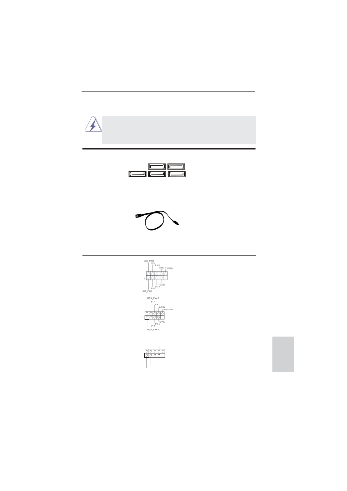
1.4 Cabezales y Conectores en Placas
Los conectores y cabezales en placa NO son puentes. NO coloque
las cubiertas de los puentes sobre estos cabezales y conectores. El
colocar cubiertas de puentes sobre los conectores y cabezales provocará un daño permanente en la placa base.
Conexiones de serie ATA3 Estas cinco conexiones de
(SATA3_1: vea p.2, N. 17)
(SATA3_2: vea p.2, N. 18)
(SATA3_3: vea p.2, N. 16)
(SATA3_4: vea p.2, N. 19)
(SATA3_5: vea p.2, N. 20)
serie ATA3 (SATA3) admiten
cables SATA para dispositivos
de almacenamiento internos. La
SATA3_5 SATA3_4 SATA3_2
interfaz SATAII / SATA3 actual
permite una velocidad de
transferencia de 6.0 Gb/s.
Cable de datos de Cualquier extremo del cable de
serie ATA (SATA) los datos de SATA puede ser
(Opcional)
conectado con el disco duro
de SATA / SATAII / SATA3 o el
conectador de SATAII / SATA3
en esta placa base.
Cabezal USB 2.0 Además de cuatro puertos
(9-pin USB_4_5)
(vea p.2, N. 26)
USB 2.0 predeterminados en el
panel de E/S, hay tres bases
de conexiones USB 2.0 en
esta placa base. Cada una de
estas bases de conexiones
(9-pin USB_6_7)
(vea p.2, N. 27)
admite dos puertos USB 2.0.
SATA3_3 SATA3_1
(9-pin USB_8_9)
(vea p.2, N. 28)
USB_PWR
P-9
P+9
GND
DUMMY
1
GND
P+8
P-8
USB_PWR
ASRock 970 Extreme3 Motherboard
Español
79
Page 80

Cabezal de Módulo Infrarrojos Este cabezal soporta un
(5-pin IR1)
módulo infrarrojos de
(vea p.2, N. 29)
transmisión y recepción
wireless opcional.
IRTX
+5VSB
DUMMY
1
GND
IRRX
Español
Base de conexiones del módulo de Esta base de conexiones se
infrarrojos para el consumidor puede utilizar para conectar
(4-pin CIR1)
(vea p.2, N. 25)
receptor remoto.
Conector de audio de Este es una interface para
panel frontal cable de audio de panel frontal
(9-pin HD_AUDIO1)
(vea p.2, N. 32)
que permite conexión y control
conveniente de apparatos de
1
Audio.
GND
PRESENCE#
MIC2_R
MIC2_L
1
MIC_RET
J_SENSE
OUT2_R
IRRX
ATX+5VSB
OUT_RET
OUT2_L
IRTX
GND
1. El Audio de Alta Defi nición soporta la detección de conector, pero
el cable de panel en el chasis debe soportar HDA para operar
correctamente. Por favor, siga las instrucciones en nuestro manual y
en el manual de chasis para instalar su sistema.
2. Si utiliza el panel de sonido AC’97, instálelo en la cabecera de sonido
del panel frontal de la siguiente manera:
A. Conecte Mic_IN (MIC) a MIC2_L.
B. Conecte Audio_R (RIN) a OUT2_R y Audio_L (LIN) en OUT2_L.
C. Conecte Ground (GND) a Ground (GND).
D. MIC_RET y OUT_RET son sólo para el panel de sonido HD. No
necesitará conectarlos al panel de sonido AC’97.
E. Activación del micrófono frontal.
En sistemas operativos Windows
®
XP / XP 64-bit:
Seleccione “Mixer” (Mezclador). Seleccione “Recorder” (Grabadora).
A continuación, haga clic en “FrontMic” (Micrófono frontal).
En sistemas operativos Windows
®
7 / 7 64-bit / VistaTM / VistaTM 64-bit:
Acceda a la fi cha “FrontMic” (Micrófono frontal) del panel de control
Realtek. Ajuste la posición del control deslizante “Recording Volume”
(Volumen de grabación).
Cabezal de panel de sistema Este cabezar acomoda varias
(9-pin PANEL1)
(vea p.2, N. 23)
dunciones de panel frontal de
sistema.
80
ASRock 970 Extreme3 Motherboard
Page 81

Conecte el interruptor de alimentación, el interruptor de restablecimiento
y el indicador de estado del sistema situados en el chasis con esta
cabecera en función de las siguientes asignaciones de contacto. Preste
atención a los contactos positivos y negativos antes de conectar los
cables.
PWRBTN (interruptor de alimentación):
Conecte el interruptor de encendido situado en el panel frontal del
chasis. Puede confi gurar la forma de apagar su sistema mediante el
interruptor de alimentación.
RESTABLECER (interruptor de restablecimiento):
Conecte el interruptor de restablecimiento situado en el panel frontal del
chasis. Pulse el interruptor de restablecimiento para restablecer el
equipo si se bloquea y no se reinicia con normalidad.
PLED (LED de alimentación del sistema):
Conecte el indicador de estado de alimentación situado en el panel
frontal del chasis. El LED se enciende cuando el sistema esté en
funcionamiento. El LED parpadea cuando el sistema se encuentre en
estado de suspensión S1. El LED se apaga cuando el sistema se
encuentre en estado de suspensión S3/S4 o se apaga (S5).
HDLED (LED de actividad del disco duro):
Conecte el LED de actividad de disco duro situado en el panel frontal
del chasis. El LED se enciende cuando el disco duro esté leyendo o
escribiendo datos.
Es posible que el diseño del panel frontal varíe en función del chasis. Un
módulo del panel frontal consiste principalmente de interruptor de
alimentación, interruptor de restablecimiento, LED de alimentación, LED
de actividad del disco duro, altavoz, etc. Al conectar el módulo del panel
frontal del chasis a esta cabecera, asegúrese de que las asignaciones
de cables y las asignaciones de contactos coincidan correctamente.
Cabezal del altavoz del chasis Conecte el altavoz del chasis a
(4-pin SPEAKER1)
(vea p.2, N. 24)
su cabezal.
Cabecera de indicador LED de encendido Conecte el indicador LED de
(3-pin PLED1)
(vea p.2, N. 22)
estado de encendido del
encendido del chasis a esta
cabecera para conocer el
1
PLED+
PLED+
PLED-
sistema. El indicador LED se
encenderá si el sistema se
encuentra en funcionamiento.
El indicador LED parpadeará
en el estado S1. El indicador
LED se apagará en los estados
S3/S4 o S5 (apagado).
ASRock 970 Extreme3 Motherboard
Español
81
Page 82

Conectores de ventilador de chasis
y alimentación
(4-pin CHA_FAN1)
(vea p.2, N. 12)
(3-pin CHA_FAN2)
(vea p.2, N. 15)
(3-pin CHA_FAN3)
(vea p.2, N. 2)
GND
+12V
CHA_FAN_SPEED
FAN_SPEED_CONTROL
GND
+12V
CHA_FAN_SPEED
Por favor, conecte los cables
del ventilador a los conectores
de ventilador, haciendo coincidir
el cable negro con la patilla de
masa. La velocidad del ventilador CHA_FAN1/2/3 se puede
controlar mediante UEFI o
AXTU.
Español
(3-pin PWR_FAN1)
(vea p.2, N. 10)
Conector del ventilador Conecte el cable del ventilador
de la CPU de la CPU a este conector y
(4-pin CPU_FAN1)
(vea p.2, N. 6)
haga coincidir el cable negro
con el conector de tierra.
GND
+12V
PWR_FAN_SPEED
FAN_SPEED_CONTROL
CPU_FAN_SPEED
+12V
GND
1 2 3 4
Aunque esta placa base proporciona compatibilidad para un ventilador
(silencioso) de procesador de 4 contactos, el ventilador de procesador
de 3 contactos seguirá funcionando correctamente incluso sin la función
de control de velocidad del ventilador. Si pretende enchufar el ventilador
de procesador de 3 contactos en el conector del ventilador de
procesador de esta placa base, conéctelo al contacto 1-3.
Contacto 1-3 conectado
Instalación del ventilador de 3 contactos
(3-pin CPU_FAN2)
(vea p.2, N. 5)
Cabezal de alimentación ATX Conecte la fuente de
(24-pin ATXPWR1)
(vea p.2, N. 9)
GND
+12V
CPU_FAN_SPEED
12 124
alimentación ATX a su cabezal.
82
13
ASRock 970 Extreme3 Motherboard
Page 83
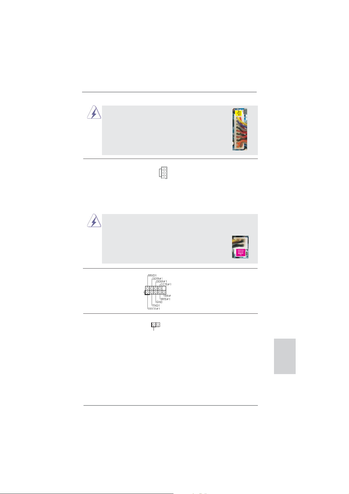
A pesar de que esta placa base incluye in conector
de alimentación ATX de 24 pins, ésta puede funcionar
incluso si utiliza una fuente de alimentación ATX de
20 pins tradicional. Para usar una fuente de
alimentación ATX de 20 pins, por favor, conecte su
fuente de alimentación usando los Pins 1 y 13.
Instalación de una Fuente de Alimentación ATX de 20 Pins
12
1
24
13
Conector de ATX 12V power Tenga en cuenta que es
(8-pin ATX12V1)
(vea p.2, N. 1)
necesario conectar este
conector a una toma de
5 1
8 4
corriente con el enchufe ATX
12V, de modo que proporcione
sufi ciente electricidad. De lo
contrario no se podrá encender.
Aunque esta placa base proporciona un conector de energía de 8-pin ATX 12V,
puede todavía trabajar si usted adopta un fuente tradicional de energía de 4-pin
ATX 12V. Para usar el fuente de energía de 4-pin ATX 12V, por favor conecte
su fuente de energía junto con Pin 1 y Pin 5.
Instalación de Fuente de Energía de 4-Pin ATX 12V
5 1
8 4
Cabezal del puerto COM Este cabezal del puerto COM
(9-pin COM1)
(vea p.2, N. 30)
se utiliza para admitir un
módulo de puerto COM.
Cabecera HDMI_SPDIF Cabecera HDMI_SPDIF. Ofrece
(HDMI_SPDIF1 de 2 pin)
(vea p.2, N. 31)
VGA HDMI, permite al sistema
una salida SPDIF la tarjeta
1
GND
SPDIFOUT
conectarse a dispositivos de
TV Digital HDMI / proyectores /
Dispositivos LCD. Conecte el
conector HDMI_SPDIF de la
tarjeta VGA HDMI a esta
cabecera.
Español
ASRock 970 Extreme3 Motherboard
83
Page 84

2. BIOS Información
El Flash Memory de la placa madre deposita SETUP Utility. Durante el Power-Up
(POST) apriete <F2> o <Del> para entrar en la BIOS. Sí usted no oprime ninguna
tecla, el POST continúa con sus rutinas de prueba. Si usted desea entrar en la
BIOS después del POST, por favor reinicie el sistema apretando <Ctl> + <Alt> +
<Borrar>, o apretando el botón Reset en el panel del ordenador. Para información
detallada sobre como confi gurar la BIOS, por favor refi érase al Manual del Usuario
(archivo PDF) contenido en el CD.
3. Información de Software Support CD
Esta placa-base soporta diversos tipos de sistema operativo Windows®: 7 / 7 64
bits / VistaTM / Vista
la placa-base trae todos los drivers y programas utilitarios para instalar y confi gurar
la placa-base. Para iniciar la instalación, ponga el CD en el lector de CD y se desplegará el Menú Principal automáticamente si «AUTORUN» está habilitado en su
computadora.
Si el Menú Principal no aparece automáticamente, localice y doble-pulse en el archivo “ASSETUP.EXE” para iniciar la instalación.
TM
64 bits / XP / XP 64 bits. El CD de instalación que acompaña
Español
84
ASRock 970 Extreme3 Motherboard
Page 85

1. Введение
Благодарим вас за покупку материнской платы ASRock 970 Extreme3 надежной
материнской платы, изготовленной в соответствии с постоянно предъявляемыми ASRock
жесткими требованиями к качеству. Она обеспечивает превосходную производительность
и отличается отличной конструкцией, которые отражают приверженность ASRock качеству
и долговечности.
Данное руководство по быстрой установке включает вводную информацию о материнской
плате и пошаговые инструкции по ее установке.
можно найти в руководстве пользователя на компакт-диске поддержки.
Спецификации материнской платы и программное обеспечение
BIOS иногда изменяются, поэтому содержание этого руководства
может обновляться без уведомления. В случае любых
модификаций руководства его новая версия будет размещена на
веб-сайте ASRock без специального уведомления. Кроме того,
самые свежие списки поддерживаемых модулей памяти и
процессоров можно найти на сайте ASRock.
Адрес веб-сайта ASRock http://www.asrock.com
При необходимости технической поддержки по вопросам данной
материнской платы посетите наш веб-сайт для получения
информации об используемой модели.
www.asrock.com/support/index.asp
1.1 Комплектность
Материнская плата ASRock 970 Extreme3
(форм-фактор ATX: 12,0 x 8,6 дюйма / 30,5 x 21,8 см)
Руководство по быстрой установке ASRock 970 Extreme3
Компакт-диск поддержки ASRock 970 Extreme3
2 x кабель данных Serial ATA (SATA) (дополнительно)
1 x I/O Щит Группы ввода / вывода
Более подробные сведения о плате
ASRock напоминает...
Для обеспечения максимальной производительности ОС Windows
7 / 7 64-bit / Vista
параметра Storage Configuration (Конфигурация запоминающего
устройства) режим AHCI. Подробные сведения о настройке BIOS см.
в руководстве пользователя на прилагаемом компакт-диске.
TM
/ VistaTM 64-bit рекомендуется в BIOS выбрать для
ASRock 970 Extreme3 Motherboard
®
Русский
85
Page 86

Русский
1.2 Спецификации
Платформа - форм-фактор ATX: 12,0 x 8,6 дюйма / 30,5 x 21,8 см
- Весь Твердый Конденсаторный проект (высококачественные
конденсаторы с проводящим полимером; на 100% сделано в
Японии)
Процессор - Поддержка Socket AM3+ процессоров
- Поддержка Socket AM3 процессоров: AMD Phenom
X2 (не поддерживаются 920 / 940) / Athlon II X4 / X3 / X2 / Sempron
- Поддержка восемьиядерных процессоров
- Поддержка UCC (Unlock CPU Core) (см. ОСТОРОЖНО, пункт 1)
- Технология V4 + 1 Power Phase Design
- Поддержка процессоров мощностью до 140 Вт
- Поддержка технологии AMD Cool ‘n’ Quiet
TM
- FSB 2400 MHz (4.8 GT/s)
- Поддержка технологии Untied Overclocking
(см. ОСТОРОЖНО, пункт 2)
- Поддержка технологии Hyper-Transport 3.0 (HT 3.0)
Набор микросхем - Северный мост: AMD 970
- Южный мост: AMD SB950
Память - Поддержка технологии Dual Channel DDR3 Memory Technology
(см. ОСТОРОЖНО, пункт 3)
- 4 x гнезда DDR3 DIMM
- Поддержите DDR3 2100(OC)/1866(OC)/1800(OC)/1600(OC)/1333/
1066/800 не- ECC, безбуферная память (см. ОСТОРОЖНО, пункт 4)
- Mакс. 32 Гб (см. ОСТОРОЖНО, пункт 5)
Гнезда - 2 x слота PCI Express 2.0 x16
расширения (PCIE2: режим x16; PCIE4: режим x4)
- 2 x гнезда
- 2 x гнезда PCI
- Поддерживает AMD
PCI Express 2.0 x1
TM
Quad CrossFireXTM и CrossFireXTM
Аудиосистема - 7.1 CH HD Аудио HD с Довольной Защитой
(Кодер-декодер Аудио Realtek ALC892)
- Поддержка Premium Blu-ray audio
- Поддержка технологии THX TruStudio
TM
ЛВС - PCIE x 1 Gigabit LAN 10/100/1000 Mb/s
- Realtek RTL8111E
- поддержка Wake-On-LAN
- Поддержка определения кабеля ЛВС
- Поддержка энергосберегающего интерфейса Ethernet 802.3az
- Поддерживается PXE
Разъемы ввода- I/O Panel
вывода на задней - 1 x порт мыши PS/2
панели - 1 x порт клавиатуры PS/2
- 1 x порт Coaxial SPDIF Out
- 1 x порт Optical SPDIF Out
- 4 x порта USB 2.0 на задней панели в стандартной конфигурации
TM
II X6 / X4 / X3 /
86
ASRock 970 Extreme3 Motherboard
Page 87

- 2 x порта USB 3.0 на задней панели в стандартной
конфигурации
- 1 x eSATA3 порт
- Разъем 1 x RJ-45 LAN с светодиодным индикатором (индикатор
ACT/LINK и индикатор SPEED)
- Соединитель звуковой подсистемы: боковая колонка / тыльная
колонка / центральная / субвуфер / линейный вход / передняя
колонка / микрофон (см. ПРЕДУПРЕЖДЕНИЕ 6)
SATA 3 - 5 x портов SATA3 со скоростью передачи данных 6,0 Гбит/с,
поддержка функций RAID (RAID 0, RAID 1, RAID 5 и RAID 10), NCQ,
AHCI и «горячего подключения»
USB 3.0 - 2 x
поддержкой интерфейсов USB 1.0/2.0/3.0 и скорости передачи
данных до 5 Гбит/с
Колодки и - 5 x разъема SATA3 6,0 Гбит/с
плате - 1 x Колодка инфракрасного модуля
- 1 x
- 1 x Колодка COM
- 1 x Колодка HDMI_SPDIF
- 1 x разъем Power LED
- соединитель: CPU/Chassis/Power FAN
- 24-контактный Колодка питания AT X
- 8-контактный Разъем ATX 12 В
- Аудиоразъем передней панели
- 3 x Колодка USB 2.0 (одна колодка для поддержки 6
дополнительных портов USB 2.0
BIOS - 32Mb AMI UEFI Legal BIOS с поддержкой rpaфичеckoro интеpфeйca
поль зователя
- поддержка “Plug and Play”
- ACPI 1.1, включение по событиям
- поддержка режима настройки без перемычек
- поддержка SMBIOS 2.3.1
- Регулировка напряжений CPU, VCCM, NB, SB
Компактдиск - Драйверы,
поддержки программы CyberLink MediaEspresso 6.5, AMD OverDriveTM, AMD
Fusion, AMD Fusion Media Explorer, пакет ASRock Software Suite
(CyberLink DVD Suite – OEM-версия и пробная версия; ASRock
MAGIX Multimedia Suite - поставщик)
Уникальная - ASRock Extreme Tuning Utility (AXTU) (см. ОСТОРОЖНО, пункт 7)
Особенность - ASRock Instant Boot
- ASRock Instant Flash (см. ОСТОРОЖНО, пункт 8)
- ASRock APP Charger (см. ОСТОРОЖНО, пункт 9)
- ASRock SmartView (см. ОСТОРОЖНО, пункт 10)
- ASRock XFast USB (см. ОСТОРОЖНО, пункт 11)
- ASRock XFast LAN (см. ОСТОРОЖНО, пункт 12)
- Технология ASRock для воспроизведения звука во включенном и
выключенном состоянии (см. ОСТОРОЖНО, пункт 13)
задних порта USB 3.0 на контроллере Etron EJ168A с
Датчик пользовательского инфракрасного модуля
Утилиты, Антивирус (пробная версия), Пробная версия
Русский
ASRock 970 Extreme3 Motherboard
87
Page 88

- Hybrid Booster:
- плавная настройка частоты процессора
(см. ОСТОРОЖНО, пункт 14)
- ASRock U-COP (см. ОСТОРОЖНО, пункт 15)
- Защита от сбоев загрузки Boot Failure Guard (B.F.G)
- Turbo UCC
Контроль - Датчики температуры процессора
оборудо- - Датчики температуры корпуса
вания - Тахометры вентиляторов CPU/Chassis/Power FAN
- Бесшумный вентилятор ЦП/системного блока
- Мультиконтроль скорости вентилятора ЦП/Шасси
- Контроль= напряжения: +12V, +5V, +3.3V, Vcore
Операцион - Совместимость с Microsoft
/ Поддержка 64-разрядной версии VistaTM / XP / XP 64-bit
®
Windows® 7 / 7 64-bit / Vista
TM
ные - FCC, CE, WHQL
системы - Совместимость с ErP/EuP Ready (требуется блок питания
Сертификаты совместимый с ErP/EuP) (см. ОСТОРОЖНО, пункт 16)
* Для детальной информации продукта, пожалуйста посетите наш вебсайт:
http://www.asrock.com
ВНИМАНИЕ
Следует понимать, что с оверклокингом связан определенный риск во всех случаях,
включая изменение установок BIOS, применение технологии Untied Overclocking или
использование инструментов оверклокинга сторонних производителей. Оверклокинг
может повлиять на стабильность работы системы и даже вызвать повреждение
входящих в нее компонентов и устройств. Приступая к оверклокингу, вы полностью
берете на себя все связанные с ним
риски и расходы. Мы не будем нести
ответственность за любые возможные повреждения в результате оверклокинга.
Русский
88
ASRock 970 Extreme3 Motherboard
Page 89

ОСТОРОЖНО!
1. Функция ASRock UCC (Unlock CPU Core) делает разблокировку
процессоров AMD простой. При помощи переключателя Unlock CPU
Core в UEFI вы можете разблокировать дополнительные ядра и
наслаждаться бесплатным увеличением производительности! При
включении UCC в случае с дву- и трехядерными процессорами они
превратятся в четырехядерные. У некоторых четырехъядерных моделей
можно разблокировать дополнительную кэш-память L3 (до 6 Мбайт).
Пожалуйста, учтите, что функция UCC поддерживается только при
работе с процессорами AMD для Socket AM3/AM3+. Примечание: не
каждый процессор будет стабильно работать после разблокировки,
скрытые ядра могут работать некорректно.
2. Данная системная плата поддерживает технологию раздельного разгона
(повышения частоты системной шины). Подробные сведения см. в
разделе «Технология раздельного разгона» на стр. 27.
3. Данная материнская плата поддерживает технологию двухканальной
памяти Dual Channel Memory Technology. Перед ее использованием
не забудьте прочитать инструкции по правильной установке модулей
памяти в руководстве по установке (стр. 14).
4. Поддержка частоты памяти 2100/1866/1800/1600 МГц зависит от
используемого процессора с разъемом AM3/AM3+. Для использования
модуля памяти DDR3 2100/1866/1800/1600 на этой материнской плате
ознакомьтесь со списком поддерживаемых модулей памяти на нашем
веб-сайте, чтобы выбрать совместимые модули памяти. Не в режиме
оверклокинга память DDR3 1866 поддерживается ЦП AM3+.
Веб-сайт ASRock http://www.asrock.com
5. В силу ограничения операционной системы фактическая емкость
памяти может быть меньше 4Гб для обеспечения резервного
места для использования системой Windows
ограничений нет для Windows® OS с 64-bit центральным процессором.
6. Поддерживается работа микрофонного входа в режимах моно и
стерео. Поддерживаются 2-, 4-, 6- и 8-канальный режимы вывода звука.
Соответствующие схемы подключения описаны на стр. 3.
7. Служебная программа ASRock Extreme Tuning Utility (AXTU) – это
универсальное средство тонкой настройки различных функций системы
с удобным и понятным интерфейсом, включающая разделы Hardware
Monitor (Наблюдение за оборудованием), Fan Control (Управление
вентилятором), Overclocking («Разгон» процессора), OC DNA (Параметры
«разгона») and IES (Автоматическое энергосбережение). В разделе
Hardware Monitor (Наблюдение за оборудованием) отображаются
основные характеристики аппаратных средств системы. В разделе Fan
Control (Управление вентилятором) отображается скорость вентилятора
и температура, которые можно регулировать. В разделе Overclocking
(«Разгон» процессора) можно увеличить рабочую частоту ЦПУ, чтобы
добиться оптимальной производительности системы. В разделе OC
DNA (Параметры «разгона») можно сохранить настройки «разгона
процессора в виде профиля, который потом можно предложить для
®
7 / VistaTM / XP. Таких
»
Русский
ASRock 970 Extreme3 Motherboard
89
Page 90

Русский
использования своим друзьям. Друзья смогут загрузить профиль
«разгона» на свои компьютеры и получить аналогичный результат. В
разделе IES (Автоматическое энергосбережение) можно настроить
регулятор напряжения так, что он будет уменьшать количество
работающих линий питания, чтобы поднять КПД системы без ущерба для
ее производительности во время простоя ядер ЦПУ. Чтобы узнать, как
работать
наш сайт в Интернете. Адрес сайта ASRock: http://www.asrock.com
8. ASRock Instant Flash – программа для прошивки BIOS, встроенная в
Flash ROM. Данное средство для обновления BIOS умеет работать
без входа в операционные системы, вроде MS-DOS или Windows®.
Чтобы запустить программу достаточно нажать <F6> во время
самотестирования системы (POST) или войти в BIOS при помощи
кнопки <F2> и выбрать пункт ASRock Instant Flash через меню.
Запустите программу и сохраните новый BIOS на USB-флэшку,
дискету или жесткий диск. После этого вы сможете оперативно
обновить BIOS, без необходимости подготовки дополнительной
дискеты, без установки программы прошивки. Имейте в виду, что
USB-флэшка или винчестер должны использовать файловую систему
FAT32/16/12.
9. Если вы хотите быстрее и без ограничений заряжать свои устройства
Apple, например iPhone, iPod и iPad Touch, компания ASRock
приготовила отличное решение для вас – ASRock APP Charger. Просто
установив драйвер APP Charger, вы сможете заряжать iPhone от
компьютера намного быстрее, ускорение составит до 40%. ASRock
APP Charger позволяет быстро заряжать несколько устройств Apple
одновременно и даже поддерживает непрерывную
компьютер переходит в режим ожидания (S1), режим ожидания с
сохранением данных в ОЗУ (S3), режим гибернации (S4) или режим
выключения (S5). Установив драйвер APP Charger, вы испытаете
небывалое удобство зарядки.
Веб-сайт ASRock: http://www.asrock.com/Feature/AppCharger/index.asp
10. SmartView — это интеллектуальная стартовая страница для браузера
IE, на которой отображаются наиболее посещаемые веб-сайты, история
посещений, друзья в Facebook и обновляемые потоки новостей
Эта новая функция обеспечивает более удобное использование
возможностей Интернета. Системные платы ASRock эксклюзивно
снабжаются программой SmartView, помогающей поддерживать
связь с друзьями. Программа SmartView работает в ОС Windows
64-разрядная версия/ VistaTM/VistaTM, 64-разрядная версия и браузере
IE8.Веб-сайт ASRock: http://www.asrock.com/Feature/SmartView/index.asp
11. Функция ASRock XFast USB увеличивает скорость работы устройств
USB. Рост скорости зависит от устройства.
12. ASRock XFast LAN обеспечивает более быстрый доступ к сети Интернет,
который даст описанные далее преимущества. Установка приоритетов
приложений ЛВС: можно задать оптимальный приоритет для своего
приложения и/или добавить новые программы. Более низкая латентность
с программой ASRock Extreme Tuning Utility (AXTU), посетите
зарядку, когда
.
®
7/7,
90
ASRock 970 Extreme3 Motherboard
Page 91

в игре: после установки более высокого приоритета игре в режиме
онлайн, может снизиться латентность в игре. Формирование трафика:
можно одновременно просматривать видео высокого разрешения на
Youtube и загружать файлы. Анализ данных в реальном времени: в окне
состояния можно легко определить, какие потоки данных передаются в
данный момент времени.
13. Технология ASRock для
выключенном состоянии позволяет пользователям портативных
аудиоустройств, таких как MP3-плееры и мобильные телефоны,
прослушивать с них высококачественный звук через компьютер,
даже когда компьютер выключен (или находится в режиме ACPI S5)!
Кроме того, к данной материнской плате бесплатно (дополнительно)
прилагается аудиокабель с 3,5-мм штекерами, который обеспечивает
наиболее удобное подключение
14. Хотя данная материнская плата поддерживает плавную настройку
частоты, устанавливать повышенную частоту не рекомендуется.
Использование значений частоты шины процессора отличающихся от
рекомендованных, может привести к нестабильной работе системы или
повреждению процессора и материнской платы.
15. При обнаружении перегрева процессора работа системы автоматически
завершается. Прежде чем возобновить работу системы, убедитесь
нормальной работе вентилятора процессора
на материнской плате и отсоедините шнур питания, а затем снова
подключите его. Чтобы улучшить отвод тепла, не забудьте при сборке
компьютера нанести термопасту между процессором и радиатором.
16. EuP расшифровывается как Energy Using Product. Стандарт был
разработан Европейским Союзом для определения энергопотребления
готовых систем. По требованию EuP система в выключенном состоянии
должна потреблять менее 1 Вт энергии. Для соответствия стандарту EuP
нужны соответствующие материнская плата и блок питания. Компания
Intel предложила, что совместимый с EuP блок питания должен
обеспечивать 50% эффективность линии питания 5V при потреблении
100 мА (в режиме ожидания). Сверьтесь с информацией производителей
блоков питания, чтобы выбрать модель с поддержкой EuP.
воспроизведения звука во включенном и
аудиоустройств к компьютеру.
в
ASRock 970 Extreme3 Motherboard
Русский
91
Page 92

1.3 Установка перемычек
Конфигурация перемычек иллюстрируется
на рисунке. Когда перемычка надета на
контакты, они называются “замкнутыми”
(short). Если на контактах перемычки нет,
то они называются “разомкнутыми” (open).
На иллюстрации показана 3-контактная
перемычка, у которой контакты 1 и 2
замкнуты.
Перемычка Установка Описание
Очистка CMOS
(CLRCMOS1,
3-контактная перемычка)
(см. стр. 2, п. 21)
Стандартные Очистка CMOS
Русский
Примечание.
Контактная колодка CLRCMOS1 позволяет очистить данные CMOS. Для
очистки данных и восстановления заводских системных параметров сначала
выключите компьютер и отсоедините сетевую вилку кабеля питания от
электророзетки. Выждите не менее 15 секунд и колпачковой перемычкой на 5
секунд перемкните штырьки 2 и 3 контактной колодки CLRCMOS1. Однако не
производите очистку CMOS непосредственно после обновления BIOS. Если
необходимо очистить CMOS сразу же после
перед очисткой CMOS, необходимо сначала выполнить загрузку системы, а
затем завершить ее работу. Примите во внимание, что пароль, дата, время,
профиль пользователя по умолчанию, идентификатор 1394 GUID и MAC-адрес
будут очищены только тогда, когда будет извлечена из своего гнезда батарейка
CMOS.
окончания обновления BIOS, то,
92
ASRock 970 Extreme3 Motherboard
Page 93

1.4 Колодки и разъемы на плате
Имеющиеся на плате колодки и разъемы НЕ ЯВЛЯЮТСЯ
контактами для перемычек. НЕ УСТАНАВЛИВАЙТЕ перемычки
на эти колодки и разъемы – это приведет к необратимому
повреждению материнской платы!
Разъемы Serial ATA3 Пять соединителя Serial ATA3
(SATA3_1, см. стр. 2, п. 17)
(SATA3_2, см. стр. 2, п. 18)
(SATA3_3, см. стр. 2, п. 16)
(SATA3_4, см. стр. 2, п. 19)
(SATA3_5, см. стр. 2, п. 20)
время интерфейс SATA
допускает скорость передачи
данных до \ 6,0 Гбит/с.
Информационный Информационный кабель
кабель Serial ATA (SATA) интерфейса SATA / SATAII / SATA3
(дополнительно)
не является направленным.
Любой из его соединителей может
быть подключен либо к жесткому
диску интерфейса SATA3 либо к
материнской плате.
Колодка USB 2.0 Помимо четыре стандартных
(9-контактный USB_4_5)
(см. стр. 2, п. 26)
вывода, на данной материнской
плате предусмотрено три разъема
USB 2.0. Каждый разъем USB 2.0
поддерживает два порта USB 2.0.
предназначаются для
SATA3_3 SATA3_1
подключения внутренних
устройств хранения с
использованием нтерфейсных
SATA3_5 SATA3_4 SATA3_2
кабелей SATA3. В настоящее
портов USB 2.0 на панели ввода-
(9-контактный USB_6_7)
(см. стр. 2, п. 27)
(9-контактный USB_8_9)
(см. стр. 2, п. 28)
1
USB_PWR
P-9
P-8
USB_PWR
P+9
P+8
GND
GND
DUMMY
ASRock 970 Extreme3 Motherboard
Русский
93
Page 94

Русский
Колодка инфракрасного модуля Данная колодка позволяет
(5-контактный IR1)
(см. стр. 2, п. 29)
подключить дополнительный
модуль беспроводного
инфракрасного
приемопередатчика.
IRTX
+5VSB
DUMMY
1
GND
IRRX
Датчик пользовательского инфракрасного модуля Датчик можно использовать для
(4-контактный CIR1)
(см. стр. 2, п. 25)
Аудиоразъем передней Этот интерфейс предназначен
панели для присоединения
(9-контактный HD_AUDIO1)
(см. cтр. 2, п. 32)
подключение аудиоустройств и
управление ими.
подключения дистанционный
приемник.
аудиокабеля передней панели,
обеспечивающего удобное
1
GND
PRESENCE#
MIC2_R
MIC2_L
1
ATX+5VSB
MIC_RET
J_SENSE
OUT2_R
IRRX
OUT_RET
OUT2_L
IRTX
GND
1. Система High Defi nition Audio поддерживает функцию
автоматического обнаружения разъемов (Jack Sensing), однако
для ее правильной pаботы кабель панели в корпусе должен
поддерживать HDA. При сборке системы следуйте инструкциям,
приведенным в нашем руководстве и руководстве пользователя
для корпуса.
2. Если вы используете аудиопанель AC’97, подключите ее к колодке
аудиоинтерфейса передней панели следующим образом:
A. Подключите
выводы Mic_IN (MIC) к контактам MIC2_L.
B. Подключите выводы Audio_R (RIN) к контактам OUT2_R, а
выводы Audio_L (LIN) к контактам OUT2_L.
C. Подключите выводы Ground (GND) к контактам Ground (GND).
D. Контакты MIC_RET и OUT_RET предназначены только для
аудиопанели HD. При использовании аудиопанели AC’97
подключать их не нужно.
E. Процедура активации микрофона приведена ниже.
Для ОС Windows
®
XP / XP 64-бита:
Выберите «Mixer» (Микшер). Выберите «Recorder» (Устройство
записи). Затем щелкните «FrontMic» (Передний микрофон).
Для ОС Windows
®
7 / 7 64-бита, VistaTM / VistaTM 64-бита:
Перейдите к вкладке «FrontMic» (Передний микрофон) в панели
управления Realtek. Отрегулируйте уровень «Recording
Volume» (Громкость записи).
Колодка системной панели Данная колодка обеспечивает
(9-контактный PANEL1)
(см. стр. 2, п. 23)
работу нескольких функций
передней панели системы.
94
ASRock 970 Extreme3 Motherboard
Page 95

Подключите к этому разъему кнопку питания, кнопку сброса
и индикатор состояния системы на корпусе в соответствии с
указанным ниже назначением контактов. При подключении кабелей
необходимо соблюдать полярность положительных и отрицательных
контактов.
PWRBTN (кнопка питания):
Подключите к этим контактам кнопку питания на передней панели
корпуса. Способ выключения системы
с помощью кнопки питания
можно настроить.
RESET (кнопка сброса):
Подключите к этим контактам кнопку сброса на передней панели
корпуса. Нажмите кнопку сброса для перезагрузки компьютера, если
компьютер «завис» и нормальную перезагрузку выполнить не
удается.
PLED (индикатор питания системы):
Подключите к этим контактам индикатор состояния питания на
передней панели
корпуса. Этот индикатор светится, когда система
работает. Индикатор мигает, когда система находится в режиме
ожидания S1. Этот индикатор не светится, когда система находится
в режиме ожидания S3 или S4, либо выключена (S5).
HDLED (индикатор активности жесткого диска):
Подключите к этим контактам индикатор активности жесткого диска
на передней панели корпуса. Этот индикатор светится,
когда
осуществляется считывание или запись данных на жестком диске.
Конструкция передней панели может различаться в зависимости от
корпуса. Модуль передней панели в основном состоит из кнопки
питания, кнопки сброса, индикатора питания, индикатора активности
жесткого диска, динамика и т.п. При подключении к этому разъему
модуля передней панели корпуса
удостоверьтесь, что провода
подключаются к соответствующим контактам.
Колодка динамика корпуса Подключите к этой колодке
(4-контактный SPEAKER1)
(см. стр. 2, п. 24)
кабель от динамика на корпусе
компьютера.
разъем Power LED Подключите индикатор Power LED
(3-контактный PLED1)
(см. стр. 2, п. 22)
светодиод продолжит мигать в
к этому разъему для отображения
статуса питания системы. Этот
1
PLED+
PLED+
PLED-
режиме S1. Светодиод будет
выключен в режимах S3/S4 или
S5 (система выключена).
ASRock 970 Extreme3 Motherboard
Русский
95
Page 96

Chassis и Power Fan-соединители
(4-контактный CHA_FAN1)
(см. стр. 2, п. 12)
(3-контактный CHA_FAN2)
(см. стр. 2, п. 15)
GND
+12V
CHA_FAN_SPEED
FAN_SPEED_CONTROL
GND
+12V
CHA_FAN_SPEED
Подключите кабели вентилятора
к соединителям и присоедините
черный шнур к штырю
заземления. Управление
скоростью вентиляторов CHA_
FAN1/2/3 может осуществляться
посредством UEFI или AXTU.
(3-контактный CHA_FAN3)
(см. стр. 2, п. 2)
(3-контактный PWR_FAN1)
(см. стр. 2, п. 10)
Разъем вентилятора Подключите к этому разъему
процессора кабель вентилятора процессора
(4-контактный CPU_FAN1)
(см. стр. 2, п. 6)
соответствовал контакту земли.
так, чтобы черный провод
GND
+12V
PWR_FAN_SPEED
FAN_SPEED_CONTROL
CPU_FAN_SPEED
+12V
GND
1 2 3 4
Данная материнская плата поддерживает вентиляторы процессора
с 4-контактным разъемом (функция тихого режима вентилятора),
однако вентиляторы с 3-контактным разъемом также будут успешно
работать, хотя функция управления скоростью вращения
вентилятора окажется недоступной. Если вы хотите подключить
вентилятор процессора с 3-контактным разъемом к разъему
вентилятора процессора на данной материнской плате,
для этого
следует использовать контакты 1-3.
Контакты 1-3 подключены
Установка вентилятора с 3-контактным разъемом
(3-контактный CPU_FAN2)
(см. стр. 2, п. 5)
GND
+12V
CPU_FAN_SPEED
Русский
Колодка питания ATX Подключите к этой колодке
(24-контактный ATXPWR1)
(см. стр. 2, п. 9)
кабель питания ATX.
12 124
13
96
ASRock 970 Extreme3 Motherboard
Page 97
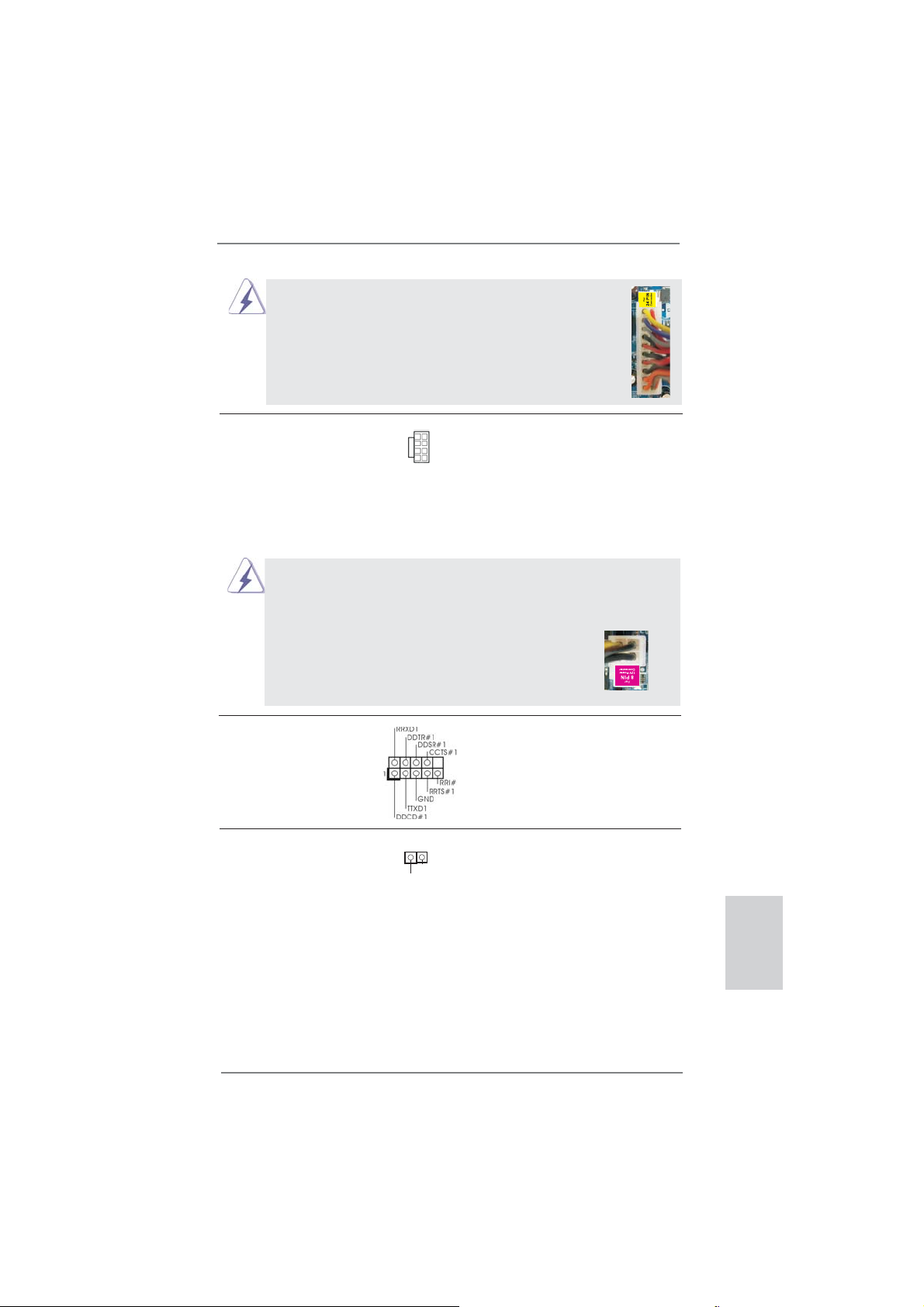
Несмотря на то, что эта материнская плата предусматр-
ивает 24-штыревой разъем питания ATX, работа будет
продолжаться, даже если адаптируется традиционный
20-штыревой разъем питания ATX. Для использования
20-штыревого разъема питания ATX вставьте источник
питания вместе со штекером 1 и штекером 13.
Установка 20-штыревого разъема питания ATX
12
1
24
13
Колодка питания 12V-ATX Обратите внимание, что к этому
(8-контактный ATX12V1)
(см. стр. 2, п. 1)
разъему необходимо
подключить вилку блока питания
ATX 12 В, чтобы обеспечить
5 1
8 4
достаточную мощность
электропитания. В противном
случае включение системы будет
невозможно.
Хотя эта объединительная плата обеспечивает ATX с 8 булавками 12V
соединитель власти, это может все еще работать, если Вы принимаете
традиционный ATX с 4-Pin 12V электропитание. Чтобы использовать
электропитание ATX с 4-Pin, пожалуйста включите ваше электропитание
наряду с Булавкой 1 и Прикрепите 5.
ATX С 4-Pin 12V Установка Электропитания
5 1
8 4
Колодка COM-порта Данная колодка COM-порта
(9-контактный COM1)
(см. стр. 2, п. 30)
позволяет подключить модуль
порта COM.
Колодка HDMI_SPDIF Колодка HDMI_SPDIF
(2-контактный HDMI_SPDIF1)
(см. стр. 2, п. 31)
аудиосигнала на VGA-карту
обеспечивает подачу выходного
1
GND
SPDIFOUT
HDMI, что позволяет подключать
к системе цифровые телевизоры,
проекторы или
жидкокристаллические панели
HDMI. Соедините эту колодку с
разъемом HDMI_SPDIF на VGA карте HDMI.
Русский
ASRock 970 Extreme3 Motherboard
97
Page 98

2. Информация о BIOS
Утилита настройки BIOS (BIOS Setup) хранится во флэш-памяти на материнской плате.
Чтобы войти в программу настройки BIOS Setup, при запуске компьютера нажмите <F2>
или <Del> во время самопроверки при включении питания (Power-On-Self-Test – POST).
Если этого не сделать, то процедуры тестирования POST будут продолжаться обычным
образом. Если вы захотите вызвать BIOS Setup уже после POST, перезапустите систему
с помощью клавиш <Ctrl> + <Alt> + <Delete> или нажатия кнопки сброса
системы. Подробную информацию о программе BIOS Setup вы найдете в Руководстве
пользователя (в формате PDF) на компакт-диске поддержки.
на корпусе
3. Информация о компакт-диске
поддержки с программным
обеспечением
Данная материнская плата поддерживает различные операционные системы Microsoft®
Windows®: 7 / 7 64-bit / VistaTM / VistaTM 64-bit / XP / XP 64-bit. Поставляемый вместе с ней
компакт-диск поддержки содержит необходимые драйверы и полезные утилиты, которые
расширяют возможности материнской платы.
Чтобы начать работу с компакт-диском поддержки, вставьте его в дисковод CD-ROM.
Если в вашем компьютере включена функция автозапуска (AUTORUN), то на экране
автоматически появится главное меню компакт-диска (Main Menu). Если этого не
произошло, найдите
дважды щелкните на нем, чтобы открыть меню.
в папке BIN на компакт-диске поддержки файл ASSETUP.EXE и
Русский
98
ASRock 970 Extreme3 Motherboard
Page 99
1. Giriş
ASRock’ın kesintisiz titiz kalite denetimi altında üretilen güvenilir bir anakart olan
ASRock 970 Extreme3 anakartını satın aldığınız için teşekkür ederiz. ASRock’ın
kalite ve dayanıklılık konusundaki kararlılığına uygun güçlü tasarımıyla mükemmel
bir performans sunar.
Bu Hızlı Takma Kılavuzu anakarta giriş ve adım adım takma kılavuzu içerir. Anakart
hakkında daha ayrıntılı bilgiyi Destek CD’sinde sunulan kullanıcı kılavuzunda bulabilirsiniz.
Anakart özellikleri ve BIOS yazılımı güncelleştirilebileceğinden bu kılavuzun içeriği
önceden haber verilmeksizin değişebilir. Bu belgede değişiklik yapılması durumun
-da, güncelleştirilmiş sürüm ayrıca haber verilmeksizin ASRock web sitesinde
sunulur. En son VGA kartlarını ve CPU destek listelerini de ASRock web sitesinde
bulabilirsiniz. ASRock web sitesi http://www.asrock.com
Bu anakartla ilgili teknik desteğe ihtiyacınız olursa, kullandığınız modele özel bilgiler
için lütfen web sitemizi ziyaret edin.
www.asrock.com/support/index.asp
1.1 Paket İçindekiler
ASRock 970 Extreme3 Anakart
(ATX Form Faktörü: 12,0-inç x 8,6-inç, 30,5 cm x 21,8 cm)
ASRock 970 Extreme3 Hızlı Takma Kılavuzu
ASRock 970 Extreme3 Destek CD’si
2 x Seri ATA (SATA) Veri Kablosu (İsteğe Bağlı)
1 x G/Ç Panel Kalkanı
ASRock Size Şunu Hatırlatır...
Windows® 7 / 7 64-bit / Vista
elde etmek için, Depolama Konfi gürasyonundaki BIOS seçeneğini AHCI
moduna ayarlamanız tavsiye edilir. BIOS ayarı için, ayrıntıları öğrenmek
üzere lütfen destek CD'mizdeki "Kullanıcı Kılavuzu"na bakın.
TM
/ VistaTM 64-bit ile daha iyi performans
ASRock 970 Extreme3 Motherboard
Türkçe
99
Page 100

Türkçe
1.2 Özellikler
Platform - ATX Form Faktörü: 12,0-inç x 8,6-inç, 30,5 cm x 21,8 cm
- Tüm Katı Kapasitör tasarımı (%100 Japon yapımı yüksek
kaliteli Polimer Kapasitörler)
CPU - Soket AM3+ işlemcileri desteği
- Soket AM3 işlemcileri desteği: AMD Phenom
X2 (920 / 940 hariç) / Athlon II X4 / X3 / X2 / Sempron
işlemcileri
- Sekiz Çekirdekli CPU Desteği
- UCC özelliğini destekler - CPU çekirdeği Kilidi Açma
(bkz. DİKKAT 1)
- V4 + 1 Güç Fazı Tasarımı
- 140W’ye kadar CPU’yu destekler
- AMD’nin Cool ‘n’ Quiet
TM
Teknolojisini Destekler
- FSB 2400 MHz (4,8 GT/sn)
- Untied Overclocking Teknolojisini destekler (bkz. DİKKAT 2)
- Hyper-Transport 3.0 (HT 3.0) Teknolojisini Destekler
Yonga seti - Kuzey Köprüsü: AMD 970
- Güney Köprüsü: AMD SB950
Bellek - Çift Kanallı DDR3 Belleği Teknolojisi (bkz. DİKKAT 3)
- 4 x DDR3 DIMM yuva
- DDR3 2100(OC)/1866(OC)/1800(OC)/1600(OC)/1333/1066/
800 ECC olmayan, ara belleksiz bellek (bkz. DİKKAT 4)
- Sistem belleğinin maks. kapasitesi: 32 GB (bkz. DİKKAT 5)
Genişletme - 2 x PCI Express 2.0 x16 yuva
Yuvası (PCIE2: x16 modu; PCIE4: x4 modu)
- 2 x PCI Express 2.0 x1 yuva
- 2 x PCI yuva
- AMD
TM
CrossFireXTM ve Quad CrossFireXTM ‘i destekler
Ses - İçerik Korumalı (Realtek ALC892 Ses Kodeki) 7,1 Kanal HD
Ses
- Premium Blu-ray ses desteği
- THX TruStudio
TM
destekler
LAN - PCIE x1 Gigabit LAN 10/100/1000 Mb/sn
- Realtek RTL8111E
- LAN’da Uyan özelliğini destekler
- LAN Kablo Algılama’yı destekler
- Enerji Verimli Ethernet 802.3az desteği
- PXE destekler
TM
II X6 / X4 / X3 /
100
ASRock 970 Extreme3 Motherboard
 Loading...