


960GM-VGS3 FX
960GM-VS3 FX
User Manual
Version 1.0
Published November 2012
Copyright©2012 ASRock INC. All rights reserved.
1
Copyright Notice:
No part of this manual may be reproduced, transcribed, transmitted, or translated in
any language, in any form or by any means, except duplication of documentation by
the purchaser for backup purpose, without written consent of ASRock Inc.
Products and corporate names appearing in this manual may or may not be regis-
tered trademarks or copyrights of their respective companies, and are used only for
identication or explanation and to the owners’ benet, without intent to infringe.
Disclaimer:
Specications and information contained in this manual are furnished for informa-
tional use only and subject to change without notice, and should not be constructed
as a commitment by ASRock. ASRock assumes no responsibility for any errors or
omissions that may appear in this manual.
With respect to the contents of this manual, ASRock does not provide warranty of
any kind, either expressed or implied, including but not limited to the implied warran-
ties or conditions of merchantability or tness for a particular purpose.
In no event shall ASRock, its directors, ofcers, employees, or agents be liable for
any indirect, special, incidental, or consequential damages (including damages for
loss of prots, loss of business, loss of data, interruption of business and the like),
even if ASRock has been advised of the possibility of such damages arising from
any defect or error in the manual or product.
This device complies with Part 15 of the FCC Rules. Operation is subject to the fol-
lowing two conditions:
(1) this device may not cause harmful interference, and
(2) this device must accept any interference received, including interference that
may cause undesired operation.
CALIFORNIA, USA ONLY
The Lithium battery adopted on this motherboard contains Perchlorate, a toxic
substance controlled in Perchlorate Best Management Practices (BMP) regulations
passed by the California Legislature. When you discard the Lithium battery in Cali-
fornia, USA, please follow the related regulations in advance.
“Perchlorate Material-special handling may apply, see
www.dtsc.ca.gov/hazardouswaste/perchlorate”
ASRock Website: http://www.asrock.com
2

Contents
1. Introduction ................................................................ 5
1.1 Package Contents ..................................................................... 5
1.2 Specications ............................................................................. 6
1.3 Unique Features ........................................................................ 9
1.4 Motherboard Layout (960GM-VGS3 FX / 960GM-VS3 FX) ..... 12
1.5 I/O Panel (960GM-VGS3 FX) .................................................. 13
1.6 I/O Panel (960GM-VS3 FX) ..................................................... 14
2. Installation .................................................................. 15
Pre-installation Precautions ................................................................ 15
2.1 CPU Installation ......................................................................... 16
2.2 Installation of CPU Fan and Heatsink ...................................... 16
2.3 Installation of Memory Modules (DIMM) .................................... 17
2.4 Expansion Slots (PCI and PCI Express Slots) ........................... 18
2.5 Multi Monitor Feature ................................................................. 19
2.6 Jumpers Setup ........................................................................... 21
2.7 Onboard Headers and Connectors ....................................... 22
2.8 Serial ATA2 (SATA2) Hard Disks Installation ......................... 26
2.9 Hot Plug and Hot Swap Functions for Serial ATA2 (SATA2)
HDDs ........................................................................................ 26
2.10 SATA2 HDD Hot Plug Feature and Operation Operation Guide 27
2.11 Driver Installation Guide ............................................................ 29
2.12 Installing Windows® 8 / 8 64-bit / 7 / 7 64-bit / VistaTM / Vista
64-bit / XP / XP 64-bit With RAID Functions .............................. 29
2.12.1 Installing Windows® XP / XP 64-bit With RAID
Functions ....................................................................... 29
2.12.2 Installing Windows® 8 / 8 64-bit / 7 / 7 64-bit / VistaTM /
Vista
TM
64-bit With RAID Functions ................................ 30
2.13 Installing Windows® 8 / 8 64-bit / 7 / 7 64-bit / VistaTM / Vista
64-bit / XP / XP 64-bit Without RAID Functions ......................... 31
2.13.1 Installing Windows® XP / XP 64-bit Without RAID
Functions ....................................................................... 31
2.13.2 Installing Windows® 8 / 8 64-bit / 7 / 7 64-bit / VistaTM /
Vista
TM
64-bit Without RAID Functions ........................... 32
2.14 Untied Overclocking Technology ............................................ 32
TM
TM
3

3. BIOS SETUP UTILITY ................................................. 33
3.1 Introduction ................................................................................ 33
3.1.1 BIOS Menu Bar ............................................................... 33
3.1.2 Navigation Keys ............................................................... 34
3.2 Main Screen ............................................................................... 34
3.3 OC Tweaker Screen................................................................... 36
3.4 Advanced Screen ...................................................................... 40
3.4.1 CPU Conguration ........................................................... 41
3.4.2 Chipset Conguration ...................................................... 42
3.4.3 ACPI Conguration .......................................................... 43
3.4.4 Storage Conguration ...................................................... 45
3.4.5 PCIPnP Conguration...................................................... 46
3.4.6 Super IO Conguration .................................................... 47
3.4.7 USB Conguration ........................................................... 48
3.5 Hardware Health Event Monitoring Screen ............................... 49
3.6 Boot Screen ............................................................................... 50
3.6.1 Boot Settings Conguration ............................................. 50
3.7 Security Screen ......................................................................... 51
3.8 Exit Screen ................................................................................ 52
4. Software Support ....................................................... 53
4.1 Install Operating System ............................................................ 53
4.2 Support CD Information ............................................................. 53
4.2.1 Running Support CD ....................................................... 53
4.2.2 Drivers Menu ................................................................... 53
4.2.3 Utilities Menu ................................................................... 53
4.2.4 Contact Information ......................................................... 53
4

1. Introduction
Thank you for purchasing ASRock 960GM-VGS3 FX / 960GM-VS3 FX motherboard,
a reliable motherboard produced under ASRock’s consistently stringent quality con-
trol. It delivers excellent performance with robust design conforming to ASRock’s
commitment to quality and endurance.
In this manual, chapter 1 and 2 contain introduction of the motherboard and step-
by-step guide to the hardware installation. Chapter 3 and 4 contain the conguration
guide to BIOS setup and information of the Support CD.
Because the motherboard specications and the BIOS software might
be updated, the content of this manual will be subject to change without
notice. In case any modications of this manual occur, the updated ver-
sion will be available on ASRock website without further notice. You may
nd the latest VGA cards and CPU support lists on ASRock website as
well. ASRock website http://www.asrock.com
If you require technical support related to this motherboard, please visit
our website for specic information about the model you are using.
www.asrock.com/support/index.asp
1.1 Package Contents
ASRock 960GM-VGS3 FX / 960GM-VS3 FX Motherboard (Micro ATX Form Factor)
ASRock 960GM-VGS3 FX / 960GM-VS3 FX Quick Installation Guide
ASRock 960GM-VGS3 FX / 960GM-VS3 FX Support CD
2 x Serial ATA (SATA) Data Cables (Optional)
1 x I/O Panel Shield
ASRock Reminds You...
To get better performance in Windows® 8 / 8 64-bit / 7 / 7 64-bit / VistaTM
/ VistaTM 64-bit, it is recommended to set the BIOS option in Storage
Conguration to AHCI mode.
5

1.2 Specications
Platform - Micro ATX Form Factor
- Solid Capacitor for CPU power
CPU - Support for Socket AM3+ processors
- Support for Socket AM3 processors: AMD PhenomTM II X6 /
X4 / X3 / X2 (except 920 / 940) / Athlon II X4 / X3 / X2 /
Sempron processors
- Supports 8-Core CPU
- Supports AMD OverDriveTM with ACC feature (Advanced
Clock Calibration)
- AMD LIVE!TM Ready
- Supports AMD’s Cool ‘n’ QuietTM Technology
- FSB 2600 MHz (5.2 GT/s)
- Supports Untied Overclocking Technology
- Supports Hyper-Transport 3.0 (HT 3.0) Technology
Chipset - Northbridge: AMD 760G
- Southbridge: AMD SB710
Memory - Dual Channel DDR3 Memory Technology
- 2 x DDR3 DIMM slots
- Support DDR3 1866(OC)/1600(OC)/1333/1066 non-ECC,
un-buffered memory (see CAUTION 1)
- Max. capacity of system memory: 16GB (see CAUTION 2)
Expansion Slot - 1 x PCI Express 2.0 x16 slot (PCIE1 @ x16 mode)
- 1 x PCI slot
Graphics - Integrated AMD Radeon 3000 graphics
- DX10 class iGPU, Pixel Shader 4.0
- Max. shared memory 512MB
- Supports D-Sub with max. resolution up to 2048x1536 @
60Hz
Audio - 5.1 CH HD Audio (Realtek ALC662 Audio Codec)
LAN - 960GM-VGS3 FX
Atheros® PCIE x1 Gigabit LAN AR8151,
speed 10/100/1000 Mb/s
- 960GM-VS3 FX
Atheros® PCIE x1 LAN AR8152, speed 10/100 Mb/s
- Supports Wake-On-LAN
- Supports PXE
Rear Panel I/O I/O Panel
- 1 x PS/2 Mouse Port
- 1 x PS/2 Keyboard Port
6

- 1 x VGA Port
- 4 x Ready-to-Use USB 2.0 Ports
- 1 x RJ-45 LAN Port with LED (ACT/LINK LED and SPEED
LED)
- HD Audio Jack: Line in / Front Speaker / Microphone
Connector - 4 x SATA2 3.0 Gb/s connectors, support RAID (RAID 0,
RAID 1, RAID 10 and JBOD), NCQ, AHCI and “Hot Plug”
functions
- 1 x Chassis Intrusion header
- 1 x CPU Fan connector (4-pin)
- 1 x Chassis Fan connector (4-pin)
- 24 pin ATX power connector
- 4 pin 12V power connector
- Front panel audio connector
- 2 x USB 2.0 headers (support 4 USB 2.0 ports)
BIOS Feature - 8Mb AMI Legal BIOS
- Supports “Plug and Play”
- ACPI 1.1 Compliance Wake Up Events
- Supports jumperfree
- SMBIOS 2.3.1 Support
- CPU, VCCM, NB Voltage Multi-adjustment
Support CD - Drivers, Utilities, AntiVirus Software (Trial Version),
CyberLink MediaEspresso 6.5 Trial, Google Chrome
Browser and Toolbar
Hardware - CPU Temperature Sensing
Monitor - Chassis Temperature Sensing
- CPU Fan Tachometer
- Chassis Fan Tachometer
- CPU Quiet Fan
- CPU Fan Multi-Speed Control
- CASE OPEN detection
- Voltage Monitoring: +12V, +5V, +3.3V, Vcore
OS - Microsoft® Windows® 8 / 8 64-bit / 7 / 7 64-bit / Vista
TM
/
VistaTM 64-bit / XP / XP Media Center / XP 64-bit compliant
Certications - FCC, CE, WHQL
- ErP/EuP Ready (ErP/EuP ready power supply is required)
* For detailed product information, please visit our website: http://www.asrock.com
7

WARNING
Please realize that there is a certain risk involved with overclocking,
including adjusting the setting in the BIOS, applying Untied Overclocking
Technology, or using third-party overclocking tools. Overclocking may
affect your system’s stability, or even cause damage to the components
and devices of your system. It should be done at your own risk and
expense. We are not responsible for possible damage caused by
overclocking.
CAUTION!
1. Whether 1866/1600MHz memory speed is supported depends
on the AM3/AM3+ CPU you adopt. If you want to adopt DDR3
1866/1600 memory module on this motherboard, please refer
to the memory support list on our website for the compatible
memory modules.
ASRock website: http://www.asrock.com
2. Due to the operating system limitation, the actual memory size
may be less than 4GB for the reservation for system usage un-
der Windows® 8 / 7 / VistaTM / XP. For Windows® 64-bit OS with
64-bit CPU, there is no such limitation.
8

1.3 Unique Features
ASRock OC Tuner
ASRock OC Tuner is a user-friendly overclocking tool which al-
lows you to surveil your system by hardware monitor function
and overclock your hardware devices to get the best system
performance under Windows® environment. Please visit our
website for the operation procedures of ASRock OC Tuner.
ASRock Intelligent Energy Saver
Featuring an advanced proprietary hardware and software de-
sign, Intelligent Energy Saver is a revolutionary technology that
delivers unparalleled power savings. The voltage regulator can
reduce the number of output phases to improve efciency when
the CPU cores are idle. In other words, it is able to provide ex-
ceptional power saving and improve power efficiency without
sacrificing computing performance. To use Intelligent Energy
Saver function, please enable Cool ‘n’ Quiet option in the BIOS
setup in advance. Please visit our website for the operation pro-
cedures of Intelligent Energy Saver.
ASRock Instant Boot
ASRock Instant Boot allows you to turn on your PC in just a few
seconds, provides a much more efcient way to save energy,
time, money, and improves system running speed for your sys-
tem. It leverages the S3 and S4 ACPI features which normally
enable the Sleep/Standby and Hibernation modes in Windows®
to shorten boot up time. By calling S3 and S4 at specic timing
during the shutdown and startup process, Instant Boot allows
you to enter your Windows® desktop in a few seconds.
ASRock Instant Flash
ASRock Instant Flash is a BIOS ash utility embedded in Flash
ROM. This convenient BIOS update tool allows you to update
system BIOS without entering operating systems rst like MS-
DOS or Windows®. With this utility, you can press the <F6> key
during the POST or the <F2> key to enter into the BIOS setup
menu to access ASRock Instant Flash. Just launch this tool and
save the new BIOS le to your USB ash drive, oppy disk or
hard drive, then you can update your BIOS only in a few clicks
without preparing an additional oppy diskette or other
9

complicated flash utility. Please be noted that the USB flash
drive or hard drive must use FAT32/16/12 le system.
ASRock OC DNA
The software name itself – OC DNA literally tells you what it is
capable of. OC DNA, an exclusive utility developed by ASRock,
provides a convenient way for the user to record the OC set-
tings and share with others. It helps you to save your overclock-
ing record under the operating system and simplies the compli-
cated recording process of overclocking settings. With OC DNA,
you can save your OC settings as a prole and share with your
friends! Your friends then can load the OC prole to their own
system to get the same OC settings as yours! Please be noticed
that the OC prole can only be shared and worked on the same
motherboard.
ASRock APP Charger
If you d es ir e a fast er, less restricted way of c ha rg in g y ou r
Apple devices, such as iPhone/iPad/iPod Touch, ASRock has
prepared a wonderful solution for you - ASRock APP Charger.
Simply install the APP Charger driver, it makes your iPhone
charge much quickly from your computer and up to 40% faster
than before. ASRock APP Charger allows you to quickly charge
many Apple devices simultaneously and even supports continu-
ous charging when your PC enters into Standby mode (S1),
Suspend to RAM (S3), hibernation mode (S4) or power off (S5).
With APP Charger driver installed, you can easily enjoy the mar-
velous charging experience.
ASRock XFast USB
ASRock XFast USB can boost USB stor age device perfor-
mance. The performance may depend on the properties of the
device.
ASRock XFast LAN
ASRock XFast LAN provides a faster internet access, which
includes the benefits listed below. LAN Application Prioritiza-
tion: You can congure your application’s priority ideally and/or
add new programs. Lower Latency in Game: After setting online
game’s priority higher, it can lower the latency in games. Trafc
Shaping: You can watch Youtube HD videos and download
10

simultaneously. Real-Time Analysis of Your Data: With the sta-
tus window, you can easily recognize which data streams you
are transferring currently.
ASRock XFast RAM
ASRock XFast RAM fully utilizes the memory space that cannot
be used under Windows® OS 32-bit CPU. ASRock XFast RAM
shortens the loading time of previously visited websites, mak-
ing web surng faster than ever. And it also boosts the speed of
Adobe Photoshop 5 times faster. Another advantage of ASRock
XFast RAM is that it reduces the frequency of accessing your
SSDs or HDDs in order to extend their lifespan.
ASRock X-Boost
ASRock’s X-Boost Technology is a smart auto-overclocking
function and is brilliantly designed to unlock the hidden power of
your CPUs. Simply press “X” when turning on the PC, X-Boost
will automatically overclock the relative components to get up to
15.77% performance boost! With the smart X-Boost, overclock-
ing CPU can become a near one-button process.
* The functionality of “Unlock CPU Cores” feature might vary by
different processors.
11
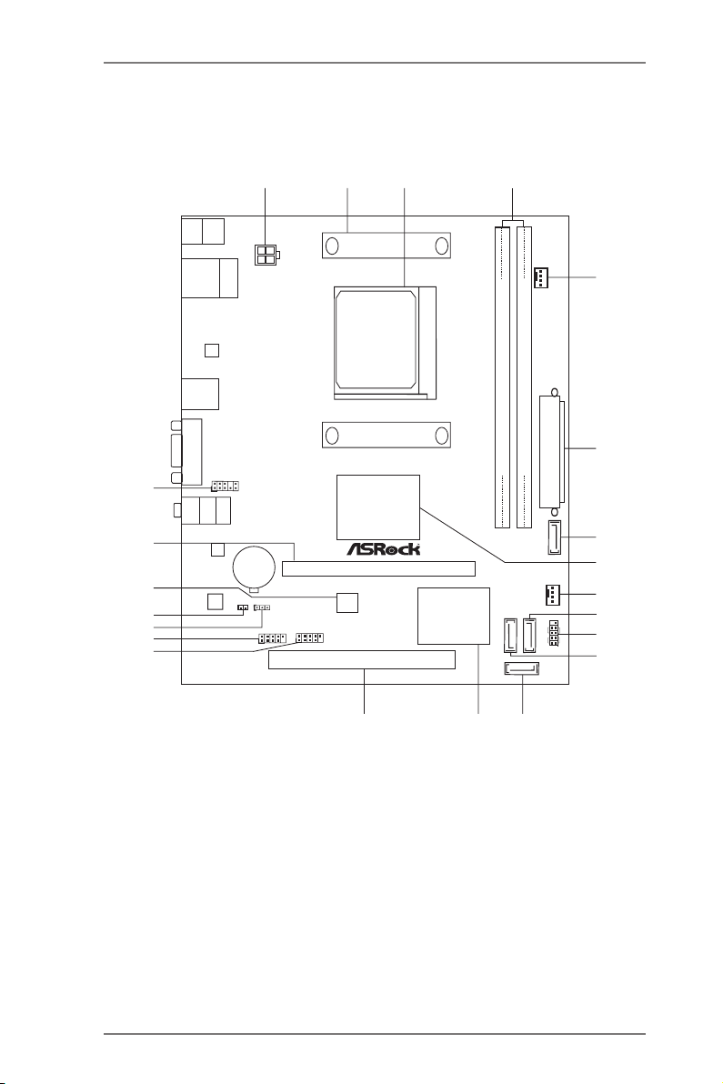
1.4 Motherboard Layout (960GM-VGS3 FX / 960GM-VS3 FX)
ATXP WR 1
AMD
760G
Chipset
PCI 1
LAN
AUDIO
CODEC
1
CLRCMOS1
CPU_FAN1
HDLED RESET
PLED PWRBTN
1
PANEL1
HD_AUDIO 1
1
RoH S
5
6
1
2
3
4
7
9
10
11
12
13
14
15
16
17
18
19
20
21
22
8Mb
BIOS
AMD
SB710
Chipse t
SATAII_4 (PORT 6)
USB8_9
1
USB6_7
1
PCIE 1
DDR 3 1 866
Top:
LINE IN
Center :
FRONT
Bottom :
MIC IN
PS2
Mouse
PS2
Keyb oard
USB 2 .0
T: USB0
B: US B1
Top:
RJ-45
USB 2 .0
T: USB2
B: US B3
FS B8 00
DDR 3_A 1 (6 4 b it, 24 0-p in mod ule )
DDR 3_B 1 (6 4 b it, 24 0-p in mod ule )
Sup po rt 8- Co re CP U
ErP /E uP R ea dy
VGA 1
ATX12V1
8
SO CKE T AM 3 b
SATAII_3 (PORT 5)
SATAII_2 (PORT 2)
SATAII_1 (PORT 1)
CHA_FAN1
CI1
1
X
Fas t RA M
X
Fas t US B
X
Fas t LA N
BAT TER Y
CMO S
1 ATX 12V Power Connector (ATX12V1) 12 SATA2 Connector (SATAII_2 (PORT 2))
2 CPU Heatsink Retention Module 13 SATA2 Connector (SATAII_1 (PORT 1))
3 AM3+ CPU Socket 14 Southbridge Controller
4 2 x 240-pin DDR3 DIMM Slots 15 PCI Slot (PCI1)
(Dual Channel: DDR3_A1, DDR3_B1) 16 USB 2.0 Header (USB8_9)
5 CPU Fan Connector (CPU_FAN1) 17 USB 2.0 Header (USB6_7)
Super
I/O
6 ATX Power Connector (ATXPWR1) 18 Clear CMOS Jumper (CLRCMOS1)
7 SATA2 Connector (SATAII_4 (PORT 6)) 19 Chassis Intrusion Header (CI1)
8 Northbridge Controller 20 SPI Flash Memory (8Mb)
9 Chassis Fan Connector (CHA_FAN1) 21 PCI Express 2.0 x16 Slot (PCIE1)
10 SATA2 Connector (SATAII_3 (PORT 5)) 22 Front Panel Audio Header (HD_AUDIO1)
11 System Panel Header (PANEL1)
12
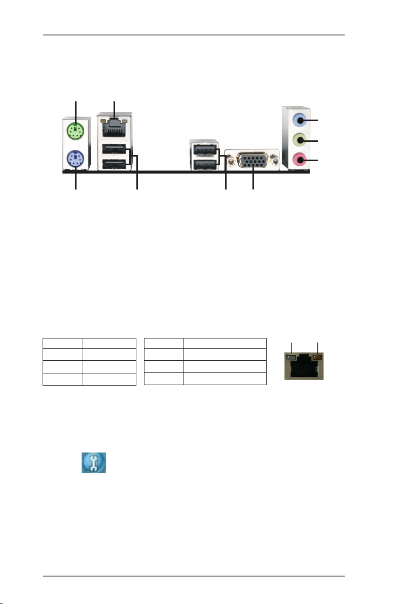
1.5 I/O Panel (960GM-VGS3 FX)
1
2
3
4
5
9
1 PS/2 Mouse Port (Green) 6 VGA Port (VGA1)
* 2 LAN RJ-45 Port 7 USB 2.0 Port (USB23)
3 Line In (Light Blue) 8 USB 2.0 Ports (USB01)
** 4 Front Speaker (Lime) 9 PS/2 Keyboard Port (Purple)
5 Microphone (Pink)
* There are two LED next to the LAN port. Please refer to the table below for the LAN port LED
indications.
Activity/Link LED SPEED LED
Status Description Status Description
8
LAN Port LED Indications
7
6
ACT/LINK
LED
SPEED
LED
Off No Link Off 10Mbps connection
Blinking Data Activity Orange 100Mbps connection
On Link Green 1Gbps connection
LAN Port
** To enable Multi-Streaming function, you need to connect a front panel audio cable to the front
panel audio header. Please refer to below steps for the software setting of Multi-Streaming.
For Windows® XP:
After restarting your computer, you will nd “Mixer” tool on your system. Please select “Mixer
ToolBox” , click “Enable playback multi-streaming”, and click “ok”. Choose “2CH” or
“4CH” and then you are allowed to select “Realtek HDA Primary output” to use Rear Speaker
and Front Speaker, or select “Realtek HDA Audio 2nd output” to use front panel audio. Then
reboot your system.
For Windows® 8 / 7 / VistaTM:
After restarting your computer, please double-click “Realtek HD Audio Manager” on the
system tray. Set “Speaker Conguration” to “Quadraphonic” or “Stereo”. Click “Device
advanced settings”, choose “Make front and rear output devices playbacks two different audio
streams simultaneously”, and click “ok”. Then reboot your system.
13
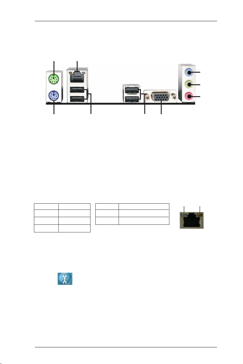
1.6 I/O Panel (960GM-VS3 FX)
1
2
3
4
5
9
1 PS/2 Mouse Port (Green) 6 VGA Port (VGA1)
* 2 LAN RJ-45 Port 7 USB 2.0 Port (USB23)
3 Line In (Light Blue) 8 USB 2.0 Ports (USB01)
** 4 Front Speaker (Lime) 9 PS/2 Keyboard Port (Purple)
5 Microphone (Pink)
* There are two LED next to the LAN port. Please refer to the table below for the LAN port LED
indications.
Activity/Link LED SPEED LED
Status Description Status Description
8
LAN Port LED Indications
7
6
ACT/LINK
LED
SPEED
LED
Off No Link Off 10Mbps connection
Blinking Data Activity Orange 100Mbps connection
On Link
LAN Port
** To enable Multi-Streaming function, you need to connect a front panel audio cable to the front
panel audio header. Please refer to below steps for the software setting of Multi-Streaming.
For Windows® XP:
After restarting your computer, you will nd “Mixer” tool on your system. Please select “Mixer
ToolBox” , click “Enable playback multi-streaming”, and click “ok”. Choose “2CH” or
“4CH” and then you are allowed to select “Realtek HDA Primary output” to use Rear Speaker
and Front Speaker, or select “Realtek HDA Audio 2nd output” to use front panel audio. Then
reboot your system.
For Windows® 8 / 7 / VistaTM:
After restarting your computer, please double-click “Realtek HD Audio Manager” on the
system tray. Set “Speaker Conguration” to “Quadraphonic” or “Stereo”. Click “Device
advanced settings”, choose “Make front and rear output devices playbacks two different audio
streams simultaneously”, and click “ok”. Then reboot your system.
14

2. Installation
This is a Micro ATX form factor motherboard. Before you install the motherboard,
study the conguration of your chassis to ensure that the motherboard ts into it.
Pre-installation Precautions
Take note of the following precautions before you install motherboard
components or change any motherboard settings.
Before you install or remove any component, ensure that the
power is switched off or the power cord is detached from the
power supply. Failure to do so may cause severe damage to the
motherboard, peripherals, and/or components.
1. Unplug the power cord from the wall socket before touching any
component.
2. To avoid damaging the motherboard components due to static elec-
tricity, NEVER place your motherboard directly on the carpet or the
like. Also remember to use a grounded wrist strap or touch a safety
grounded object before you handle components.
3. Hold components by the edges and do not touch the ICs.
4. Whenever you uninstall any component, place it on a grounded anti-
static pad or in the bag that comes with the component.
5. When placing screws into the screw holes to secure the mother-
board to the chassis, please do not over-tighten the screws! Doing
so may damage the motherboard.
15

2.1 CPU Installation
Step 1. Unlock the socket by lifting the lever up to a 90
o
angle.
Step 2. Position the CPU directly above the socket such that the CPU corner with
the golden triangle matches the socket corner with a small triangle.
Step 3. Carefully insert the CPU into the socket until it ts in place.
The CPU ts only in one correct orientation. DO NOT force the CPU
into the socket to avoid bending of the pins.
Step 4. When the CPU is in place, press it rmly on the socket while you push
down the socket lever to secure the CPU. The lever clicks on the side tab
to indicate that it is locked.
Lever 90° Up
CPU Golden Triangle
STEP 1:
Lift Up The Socket Lever
STEP 2 / STEP 3:
Match The CPU Golden Triangle
To The Socket Corner Small
Triangle
Socker Corner
Small Triangle
STEP 4:
Push Down And Lock
The Socket Lever
2.2 Installation of CPU Fan and Heatsink
After you install the CPU into this motherboard, it is necessary to install a
larger heatsink and cooling fan to dissipate heat. You also need to spray
thermal grease between the CPU and the heatsink to improve heat dis-
sipation. Make sure that the CPU and the heatsink are securely fastened
and in good contact with each other. Then connect the CPU fan to the
CPU FAN connector (CPU_FAN1, see Page 12, No. 5). For proper in-
stallation, please kindly refer to the instruction manuals of the CPU fan
and the heatsink.
16
 Loading...