

Copyright Notice:Copyright Notice:
Copyright Notice:
Copyright Notice:Copyright Notice:
No part of this installation guide may be reproduced, transcribed, transmitted, or translated in any language, in any form or by any means, except duplication of documentation by the purchaser for backup purpose, without written consent of ASRock Inc.
Products and corporate names appearing in this guide may or may not be registered
trademarks or copyrights of their respective companies, and are used only for identification or explanation and to the owners’ benefit, without intent to infringe.
Disclaimer:Disclaimer:
Disclaimer:
Disclaimer:Disclaimer:
Specifications and information contained in this guide are furnished for informational
use only and subject to change without notice, and should not be constructed as a
commitment by ASRock. ASRock assumes no responsibility for any errors or omissions
that may appear in this guide.
With respect to the contents of this guide, ASRock does not provide warranty of any kind,
either expressed or implied, including but not limited to the implied warranties or
conditions of merchantability or fitness for a particular purpose. In no event shall
ASRock, its directors, officers, employees, or agents be liable for any indirect, special,
incidental, or consequential damages (including damages for loss of profits, loss of
business, loss of data, interruption of business and the like), even if ASRock has been
advised of the possibility of such damages arising from any defect or error in the guide
or product.
This device complies with Part 15 of the FCC Rules. Operation is subject to the
following two conditions:
(1) this device may not cause harmful interference, and
(2) this device must accept any interference received, including interference that
may cause undesired operation.
CALIFORNIA, USA ONLY
The Lithium battery adopted on this motherboard contains Perchlorate, a toxic
substance controlled in Perchlorate Best Management Practices (BMP) regulations
passed by the California Legislature. When you discard the Lithium battery in
California, USA, please follow the related regulations in advance.
“Perchlorate Material-special handling may apply, see
www.dtsc.ca.gov/hazardouswaste/perchlorate”
ASRock Website: http://www.asrock.com
Published May 2013
Copyright©2013 ASRock INC. All rights reserved.
ASRock 960GM/U3S3 FX Motherboard
EnglishEnglish
EnglishEnglish
English
11
1
11
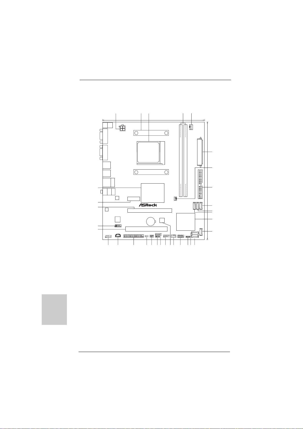
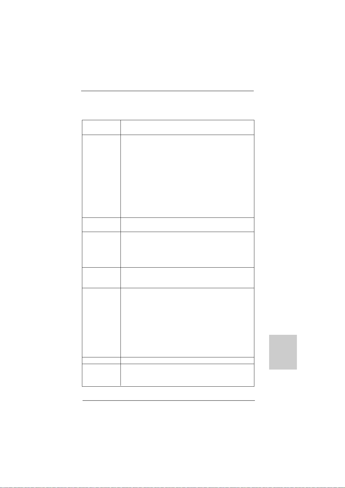
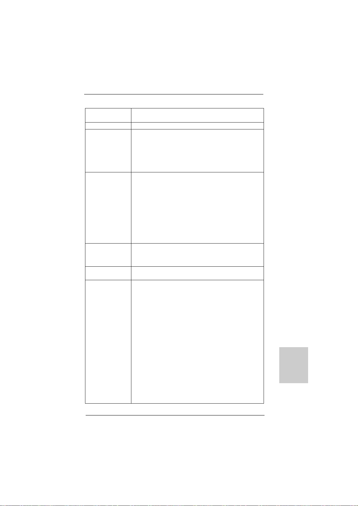
Motherboard LayoutMotherboard Layout
Motherboard Layout
Motherboard LayoutMotherboard Layout
3
1
Mouse
FRONT
Center:
PS2
Top:
RJ-45
Top:
LINE IN
LAN
19.8cm (7.8-in)
Designin Taipei
ATX12V1
Keyboard
PS2
VGA1
DVI_CON1
USB2.0
T: US B2
B:USB3
USB3.0
T: US B4
B:USB5
USB2.0
T:USB0
B:USB1
32
Bottom:
MIC IN
31
30
AUDIO
CODEC
Super
I/O
HD_AUDIO1
1
COM1
1
CD1
1
LPT1
26
27
29
28
2
ErP/EuP Ready Support 8-CoreCPU AM3+
SOCKET AM3b
USB 3.0
PCIE1
RoHS
25
AMD
760G
Chipset
PCIE2
960GM/U3S3 FX
CMOS
BATTERY
PCI1
USB6_7
IR1
CLRCMOS1
1
1
1
1
CIR1
23
22
24
8Mb
BIOS
21
FastUSB
X
SATA3 6Gb/s
CHA_FAN1
USB8_9
1
19
18
20
PWR_FAN1
4
DDR3 1866
FSB800
FastLAN
DDR3_A1 (64bit, 240-pin module)
X
AMD
SB710
Chipset
PANEL1
PLEDPWRBTN
1
HDLED RESET
17
DDR3_B1 (64bit, 240-pin module)
SPEAKER1
1
16
CPU_FAN1
15
5
SATA3_1 SATA3_2 SATAII_4
SATAII_1(PORT0)
SATAII_2(PORT1)
14
ATXPWR1
IDE1
(PORT3)
SATAII_3
(PORT2)
24.4cm (9.6-in)
6
7
8
9
10
11
12
13
English
EnglishEnglish
EnglishEnglish
22
2
22
1 ATX 12V Power Connector (ATX12V1) 17 System Panel Header (PANEL1, White)
2 CPU Heatsink Retention Module 18 Chassis Fan Connector (CHA_FAN1)
3 AM3+ CPU Socket 19 SPI Flash Memory (8Mb)
4 2 x 240-pin DDR3 DIMM Slots 20 USB 2.0 Header (USB8_9, Blue)
(Dual Channel: DDR3_A1, DDR3_B1; Blue) 21 USB 2.0 Header (USB6_7, Blue)
5 CPU Fan Connector (CPU_FAN1) 22 Consumer Infrared Module Header (CIR1)
6 ATX Power Connector (ATXPWR1) 23 Infrared Module Header (IR1)
7 Power Fan Connector (PWR_FAN1) 24 Clear CMOS Jumper (CLRCMOS1)
8 Primary IDE Connector (IDE1, Blue) 25 Print Port Header (LPT1, White)
9 SATA2 Connector (SATAII_4 (PORT 3), Blue) 26 Internal Audio Connector: CD1 (Black)
10 SATA3 Connector (SATA3_2, White) 27 Front Panel Audio Header
11 SATA3 Connector (SATA3_1, White) (HD_AUDIO1, White)
12 Southbridge Controller 28 PCI Slot (PCI1)
13 SATA2 Connector (SATAII_3 (PORT 2), Blue) 29 Serial Port Connector (COM1)
14 SATA2 Connector (SATAII_2 (PORT 1), Blue) 30 PCI Express 2.0 x16 Slot (PCIE2; Blue)
15 SATA2 Connector (SATAII_1 (PORT 0), Blue) 31 PCI Express 2.0 x1 Slot (PCIE1; Blue)
16 Chassis Speaker Header (SPEAKER 1, White)3 2 Northbridge Controller
ASRock 960GM/U3S3 FX Motherboard
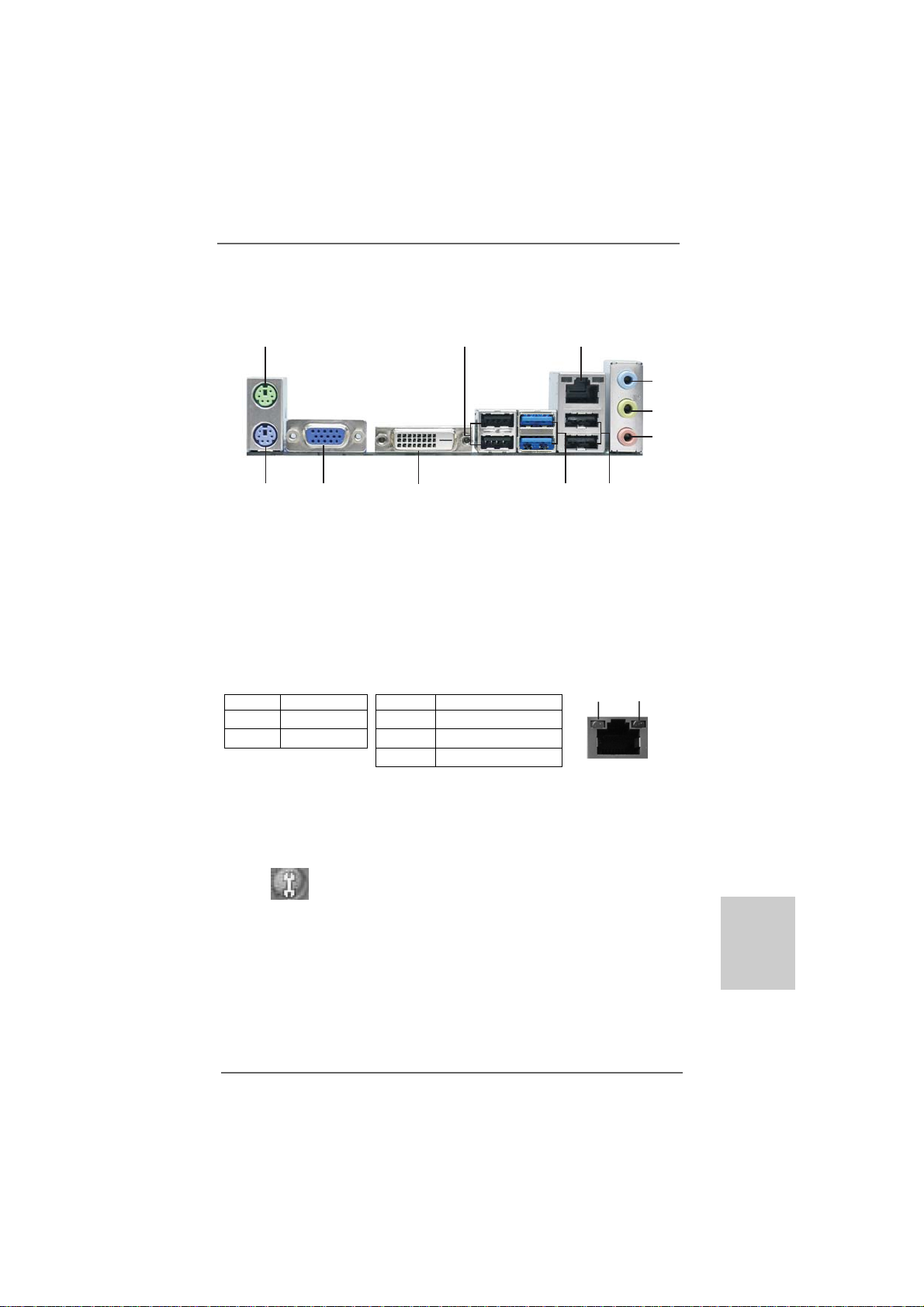
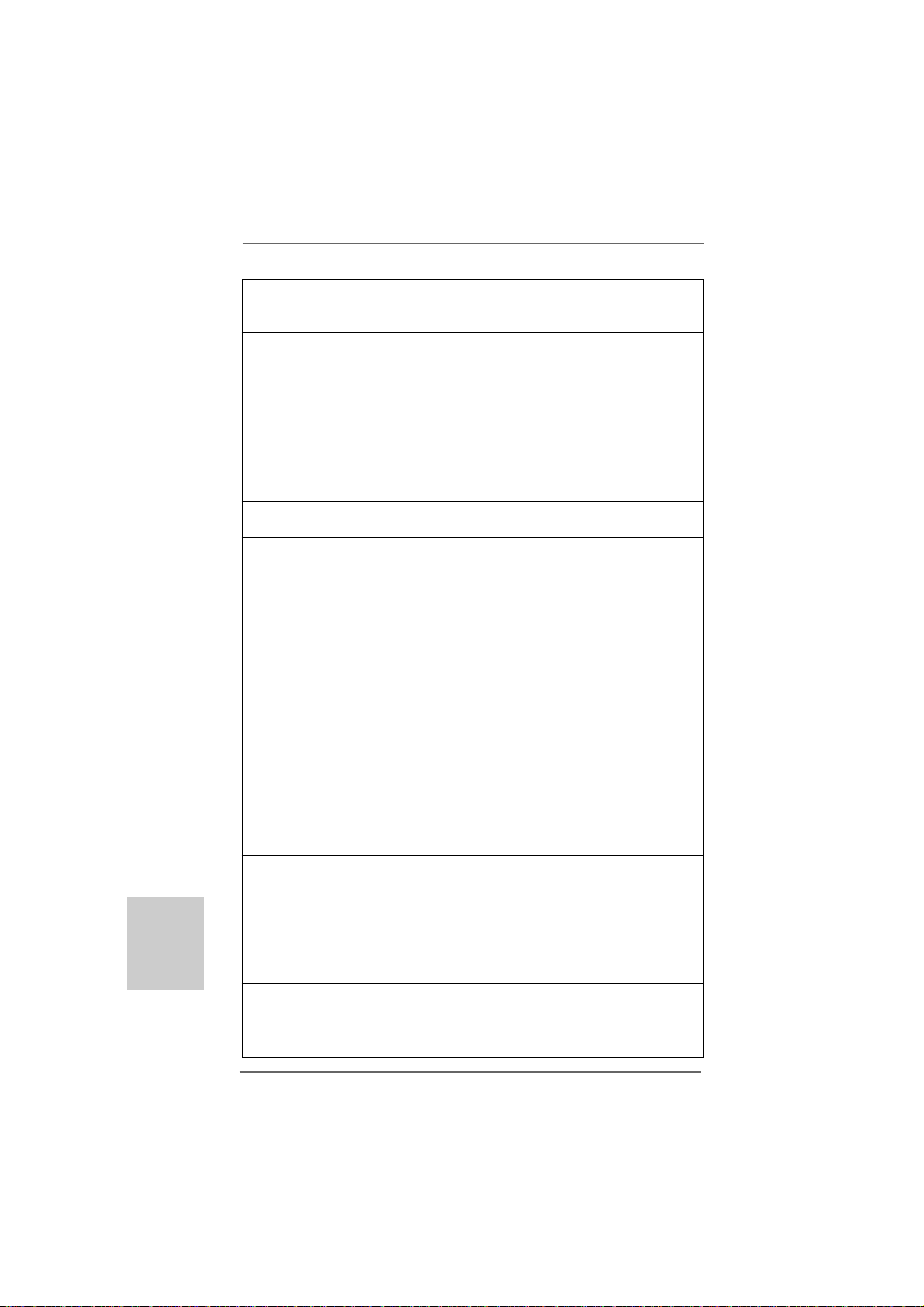
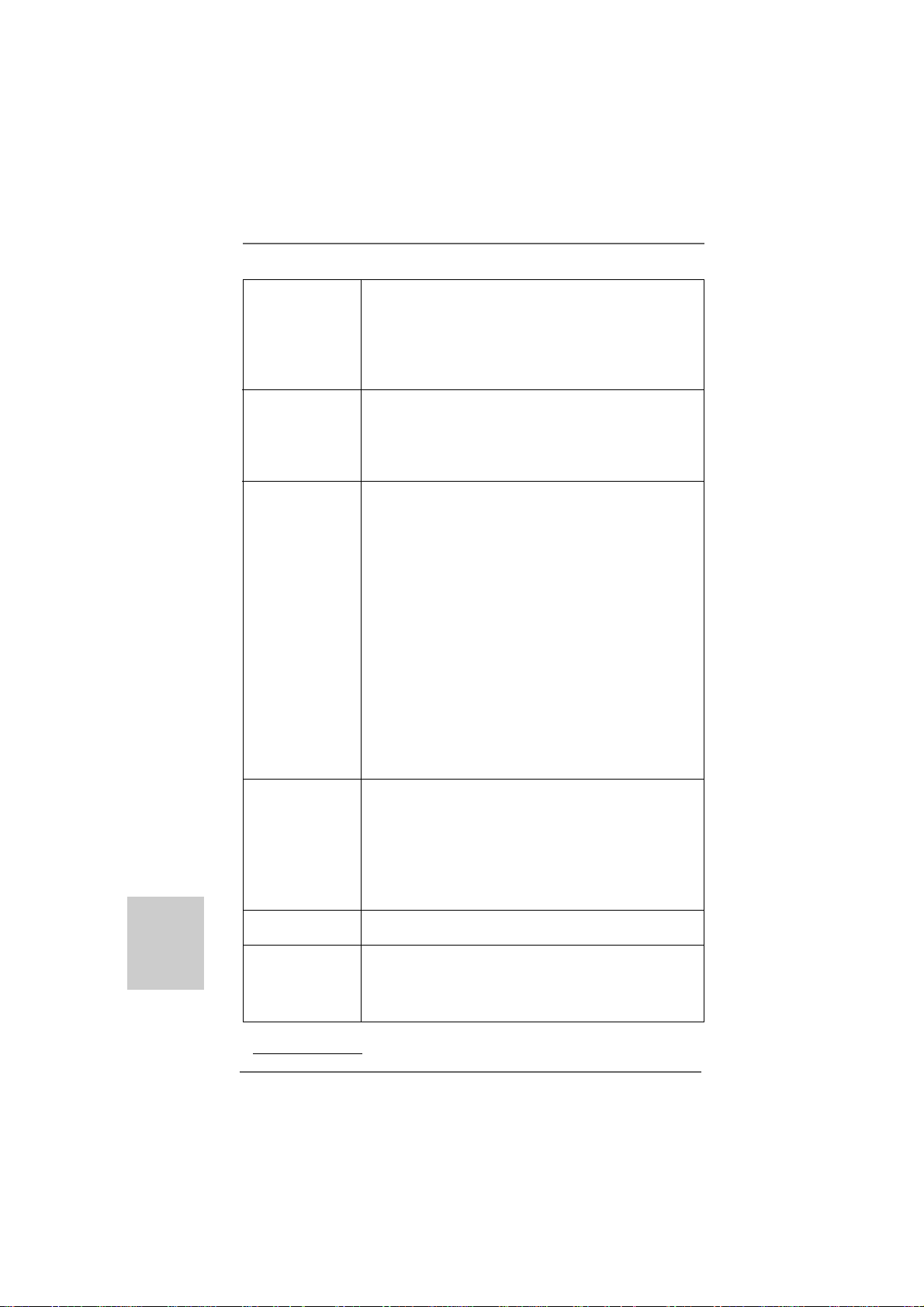
I/O PI/O P
I/O P
I/O PI/O P
anelanel
anel
anelanel
1
2
3
4
5
6
11
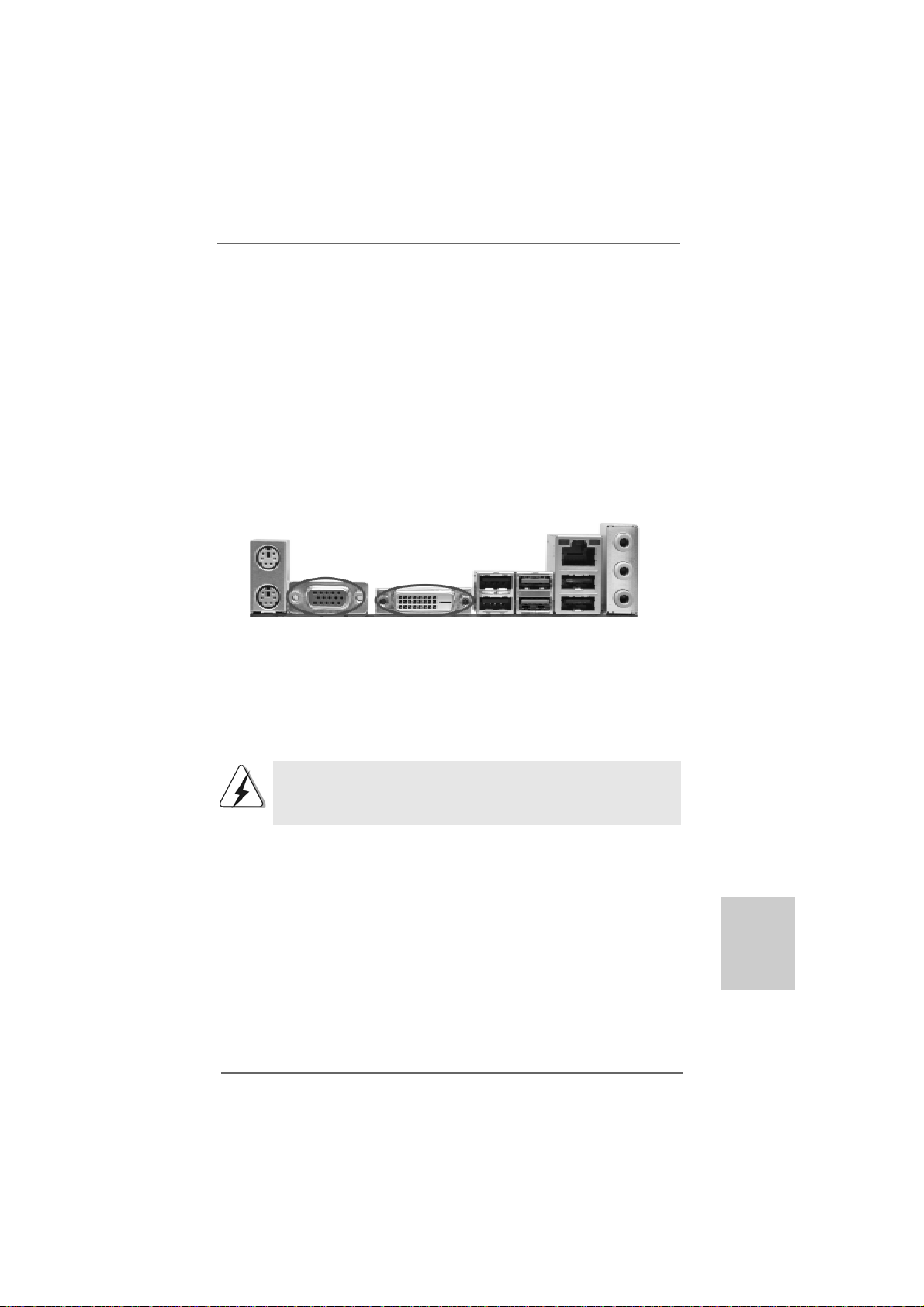
1 PS/2 Mouse Port (Green) 7 USB 2.0 Ports (USB01)
2 USB 2.0 Ports (USB23) 8 USB 3.0 Ports (USB45)
* 3 RJ-45 Port 9 DVI-D Port
4 Line In (Light Blue) 10 D-Sub Port
5 Line Out (Lime) 11 PS/2 Keyboard Port (Purple)
6 Microphone (Pink)
* There are two LED next to the LAN port. Please refer to the table below for the LAN port LED
indications.
Activity/Link LED SPEED LED
Status Description Status Description
Off No Activity Off 10Mbps connection
Blinking Data Activity Orange 100Mbps connection
10
LAN Port LED Indications
Green 1Gbps connection
9
8
ACT/LINK
LED
7
SPEED
LED
LAN Port
* To enable Multi-Streaming function, you need to connect a front panel audio cable to the front
panel audio header. Please refer to below steps for the software setting of Multi-Streaming.
For Windows® XP:
After restarting your computer, you will find “Mixer” tool on your system. Please select “Mixer
ToolBox” , click “Enable playback multi-streaming”, and click “ok”. Choose “2CH” or
“4CH” and then you are allowed to select “Realtek HDA Primary output” to use Rear Speaker
and Front Speaker, or select “Realtek HDA Audio 2nd output” to use front panel audio. Then
reboot your system.
For Windows® 7 / VistaTM:
After restarting your computer, please double-click “Realtek HD Audio Manager” on the
system tray. Set “Speaker Configuration” to “Quadraphonic” or “Stereo”. Click “Device
advanced settings”, choose “Make front and rear output devices playbacks two different audio
streams simultaneously”, and click “ok”. Then reboot your system.
ASRock 960GM/U3S3 FX Motherboard
EnglishEnglish
EnglishEnglish
English
33
3
33
1.1.
IntroductionIntroduction
1.
Introduction
1.1.
IntroductionIntroduction
Thank you for purcha sing ASRock 960GM/U3S3 FX motherboard, a reliable motherboard
produced under ASRock’s consistently stringent quality control. It delivers excellent
performance with robust design conforming to ASRock’s commitment to quality and
endurance.
In this manual, cha pter 1 a nd 2 contain introduction of the motherboard and ste p-by-step
guide to the hardware installation. Chapter 3 and 4 contain the configuration guide to
BIOS setup and information of the Support CD.
Because the motherboard specifications and the BIOS software might
be updated, the content of this manual will be subject to change without
notice. In case any modifications of this manual occur, the updated
version will be available on ASRock website without further notice. You
may find the latest VGA cards and CPU support lists on ASRock website
as well. ASRock website http://www.asrock.com
If you require technical support related to this motherboard, please visit
our website for specific information about the model you are using.
www.asrock.com/support/index.asp
1.11.1
PP
ackack
1.1
1.11.1
ASRock 960GM/U3S3 FX Motherboard
(Micro ATX Form Factor: 9.6-in x 7.8-in, 24.4 cm x 19.8 cm)
ASRock 960GM/U3S3 FX Quick Installation Guide
ASRock 960GM/U3S3 FX Support CD
2 x Serial ATA (SAT A) Data Cables (Optional)
1 x I/O Panel Shield
age Contentsage Contents
P
ack
age Contents
PP
ackack
age Contentsage Contents
English
EnglishEnglish
EnglishEnglish
44
4
44
ASRock 960GM/U3S3 FX Motherboard
1.21.2
SpecificationsSpecifications
1.2
Specifications
1.21.2
SpecificationsSpecifications
Platform - Micro ATX Form Factor: 9.6-in x 7.8-in, 24.4 cm x 19.8 cm
- Solid Capa citor f or CPU power
CPU - Support for Socket AM3+ processors
- Support for Socket AM3 processors: AMD PhenomTM II X6 /
X4 / X3 / X2 (except 920 / 940) / Athlon II X4 / X3 / X2 /
Sempron processors
- Supports 8-Core CPU
- Supports AMD OverDriveTM with ACC feature (Adva nced
Clock Calibration)
- AMD LIVE!TM Ready
- Supports AMD’s Cool ‘n’ QuietTM Technology
- FSB 2600 MHz (5.2 GT/s)
- Supports Untied Overclocking Te chnology (see CAUTION 1)
- Supports Hyper-Tran sport 3.0 (HT 3.0) Te chnology
Chipset - Northbridge: AMD 760G
- Southbridge: AMD SB710
Memory - Dual Channel DDR3 Memory Technology (see CAUTION 2)
- 2 x DDR3 DIMM slots
- Support DDR3 1866(OC)/1600(OC)/1333/1066/800 non-ECC,
un-buffered memory (see CAUTION 3)
- Max. capacity of system memory: 16GB (see CAUTION 4)
Expansion Slot - 1 x PCI Express 2.0 x16 slot (blue @ x16 mode)
- 1 x PCI Express 2.0 x1 slot
- 1 x PCI slot
Graphics - Integrated AMD Radeon HD 3000 graphics
- DX10 class iGPU, Pixel Shader 4.0
- Max. shared memory 512MB (see CAUTION 5)
- Dual VGA Output: support D VI-D and D-Sub ports by
independent display controllers
- Supports DVI with max. resolution up to 1920x1200 @ 75Hz
- Supports D-Sub with max. resolution up to 2048x1536 @ 85Hz
- Supports HDCP function with DVI-D port
- Supports Full HD 1080p Blu-ray (BD) / HD-DV D playback with
D VI-D port
Audio - 5.1 CH HD Audio (Realtek ALC662 Audio Codec)
LAN - PCIE x1 Gigabit LAN 10/100/1000 Mb/s
- Realtek RTL81 1 1E
- Supports Wa ke-On-LAN
EnglishEnglish
EnglishEnglish
English
ASRock 960GM/U3S3 FX Motherboard
55
5
55
English
EnglishEnglish
EnglishEnglish
66
6
66
- Supports LAN Cable Detection
- Supports Energy Efficient Ethernet 802.3az
- Supports PXE
Rear Panel I/O I/O Panel
- 1 x PS/2 Mouse Port
- 1 x PS/2 Keyboard Port
- 1 x D-Sub Port
- 1 x DVI-D Port
- 4 x Ready-to-Use USB 2.0 Ports
- 2 x Ready-to-Use USB 3.0 Ports
- 1 x RJ-45 LAN Port with LED (ACT/LINK LED a nd SPEED LED)
- HD Audio Jack: Line in / Front Speaker / M icrophone
SA TA3 - 2 x SATA3 6.0 Gb/s connectors by ASMedia ASM1061,
support NCQ, AHCI and "Hot Plug" functions
USB3 - 2 x USB 3.0 ports by Etron EJ168A, support USB
1.0/2.0/3.0 up to 5Gb/s
Connector - 4 x SATA2 3.0Gb/s connectors, support RAID (RAID 0, RAID 1,
RAID 10 a nd JBOD), NCQ, AHCI and “Hot Plug” functions
(see CAUTION 6)
- 2 x SATA3 6.0 Gb/s connectors
- 1 x AT A133 IDE connector (supports 2 x IDE devices )
- 1 x IR header
- 1 x CIR header
- 1 x Print port header
- 1 x COM port header
- CPU/Chassis/Power F A N connector
- 24 pin A TX power connector
- 4 pin 12V power connector
- CD in header
- Front panel audio connector
- 2 x USB 2.0 headers (support 4 USB 2.0 ports)
BIOS Feature - 8Mb AMI BIOS
- AMI Legal BIOS
- Supports “Plug and Play”
- ACPI 1.1 Compliance Wake Up Events
- Supports jumperfree
- SMBIOS 2.3.1 Support
- CPU, VCCM, NB V oltage Multi-adjustment
Support CD - Drivers, Utilities, AntiV irus Software (T rial Version),
AMD OverDriveTM Utility, CyberLink Medi aEspresso 6.5 Trial,
ASRock Software Suite (CyberLink DVD Suite - OEM and Trial;
ASRock MAGIX Multimedi a Suite - OEM)
ASRock 960GM/U3S3 FX Motherboard
Unique Feature - ASRock OC T uner (see CAUTION 7)
- ASRock Intelligent Energy Saver (see CAUTION 8)
- ASRock Instant Boot
- ASRock Instant Flash (see CAUTION 9)
- ASRock OC DNA (see CAUTION 10)
- ASRock APP Charger (see CAUTION 11)
- ASRock SmartView (see CAUTION 12)
- ASRock XFast USB (see CAUTION 13)
- ASRock XFast LAN (see CAUTION 14)
- ASRock XFast RAM (see CAUTION 15)
- Hybrid Booster:
- CPU Frequency Stepless Control (see CAUTION 16)
- ASRock U-COP (see CAUTION 17)
- Boot Failure Guard (B.F.G.)
Hardware - CPU T emperature Sensing
Monitor - Chassis Temperature Sensing
- CPU/Chassis/Power Fa n Tachometer
- CPU/Chassis Quiet Fa n
- CPU/Chassis Fa n Multi-Speed Control
- Voltage Monitoring: +12V, +5V, +3.3V, Vcore
OS - Microsoft® Windows® 7 / 7 64-bit / Vista
TM
/ VistaTM 64-bit
/ XP / XP Media Center / XP 64-bit compliant
Certifications - FCC, CE, WHQL
- ErP/EuP Ready (ErP/EuP ready power supply is required)
(see CAUTION 18)
* For detailed product information, please visit our website: http://www.asrock.com
WAR NING
Please realize that there is a certain risk involved with overclocking, including
adjusting the setting in the BIOS, applying Untied Overclocking Technology, or using
the third-party overclocking tools. Overclocking may affect your system stability, or
even cause damage to the components and devices of your system. It should be
done at your own risk and expense. We are not responsible for possible damage
caused by overclocking.
ASRock 960GM/U3S3 FX Motherboard
EnglishEnglish
EnglishEnglish
English
77
7
77

English
EnglishEnglish
EnglishEnglish
CAUTION!
1. This motherboard supports Untied Overclocking Technology. Please read
“Untied Overclocking Technology” on page 25 for details.
2. This motherboard supports Dual Channel Memory Technology. Before
you implement Dual Channel Memory Technology, make sure to read
the installation guide of memory modules on page 13 for proper
installation.
3. Whether 1866/1600MHz memory speed is supported depends on the
AM3/AM3+ CPU you adopt. If you want to adopt DD R3 1866/1600 memory
module on this motherboard, please refer to the memory support list on
our website for the compatible memory modules.
ASRock website http://www.asrock.com
4. Due to the operating system limitation, the actual memory size may be
less than 4GB for the reservation for system usage under Windows® 7
/ VistaTM / XP. For Windows® OS with 64-bit CPU, there is no such
limitation.
5. The maximum shared memory size is defined by the chipset vendor
and is subject to change. Please check AMD website for the latest
information.
6. Before installing SATAII hard disk to SATAII connector, ple ase read the “SA TAII
Hard Disk Setup Guide” on page 27 of “User Manual” in the support CD to
adjust your SATAII hard disk drive to SATAII mode. You can also connect
SATA hard disk to SATAII connector directly.
7. It is a user-friendly ASRock overclocking tool which allows you to surveil
your system by hardware monitor function and overclock your hardware
devices to get the best system performance under Windows
environment. Please visit our website for the operation procedures of
ASRock OC Tuner. ASRock website: http://www.asrock.com
8. Featuring an advanced proprietary hardware and software design,
Intelligent Energy Saver is a revolutionary technology that delivers
unparalleled power savings. The voltage regulator can reduce the number of output phases to improve efficiency when the CPU cores are idle.
In other words, it is able to provide exceptional power saving and improve power efficiency without sacrificing computing performance. To
use Intelligent Energy Saver function, please enable Cool ‘n’ Quiet option in the BIOS setup in advance. Please visit our website for the operation procedures of Intelligent Energy Saver.
ASRock website: http://www.asrock.com
®
88
8
88
ASRock 960GM/U3S3 FX Motherboard

9. ASRock Instant Flash is a BIOS flash utility embedded in Flash ROM.
This convenient BIOS update tool allows you to update system BIOS
without entering operating systems first like MS-DOS or Windows®.
With this utility, you can press <F6> key during the POST or press <F2>
key to BIOS setup menu to access ASRock Instant Flash. Just launch
this tool and save the new BIOS file to your USB flash drive, floppy disk
or hard drive, then you can update your BIOS only in a few clicks without
preparing an additional floppy diskette or other complicated flash utility.
Please be noted that the USB flash drive or hard drive must use FAT32/
16/12 file system.
10. The software name itself – OC DNA literally tells you what it is capable
of. OC DNA, an exclusive utility developed by ASRock, provides a convenient way for the user to record the OC settings and share with others.
It helps you to save your overclocking record under the operating system and simplifies the complicated recording process of overclocking
settings. With OC DNA, you can save your OC settings as a profile and
share with your friends! Your friends then can load the OC profile to their
own system to get the same OC settings as yours! Please be noticed
that the OC profile can only be shared and worked on the same
motherboard.
11. If you desire a faster, less restricted way of charging your Apple devices,
such as iPhone/iPod/iPad Touch, ASRock has prepared a wonderful
solution for you - ASRock APP Charger. Simply installing the APP Charger
driver, it makes your iPhone charged much quickly from your computer
and up to 40% faster than before. ASRock APP Charger allows you to
quickly charge many Apple devices simultaneously and even supports
continuous charging when your PC enters into Standby mode (S1),
Suspend to RAM (S3), hibernation mode (S4) or power off (S5). With
APP Charger driver installed, you can easily enjoy the marvelous charging experience than ever.
ASRock website: http://www.asrock.com/Feature/AppCharger/index.asp
12. SmartView, a new function of internet browser, is the smart start page
for IE that combines your most visited web sites, your history, your
Facebook friends and your real-time newsfeed into an enhanced view
for a more personal Internet experience. ASRock motherboards are
exclusively equipped with the SmartView utility that helps you keep in
touch with friends on-the-go. To use SmartView feature, please make
sure your OS version is Windows® 7 / 7 64 bit / VistaTM / VistaTM 64 bit,
and your browser version is IE8.
ASRock website: http://www.asrock.com/Feature/SmartView/index.asp
13. ASRock XFast USB can boost USB storage device performance. The
performance may depend on the property of the device.
EnglishEnglish
EnglishEnglish
English
ASRock 960GM/U3S3 FX Motherboard
99
9
99

14. ASRock XFast LAN provides a faster internet access, which includes
below benefits. LAN Application Prioritization: You can configure your
application priority ideally and/or add new programs. Lower Latency in
Game: After setting online game priority higher, it can lower the latency
in game. Traffic Shaping: You can watch Youtube HD video and download files simultaneously. Real-Time Analysis of Your Data: With the
status window, you can easily recognize which data streams you are
currently transferring.
15. ASRock XFast RAM fully utilizes the memory space that cannot be used
under Windows® OS 32-bit CPU. It also shortens the loading time of
previously visited websites, making web surfing faster than ever. And it
also boosts the speed of Adobe Photoshop 5 times faster. Another
advantage of ASRock XFast RAM is that it reduces the frequency of
accessing your SSDs or HDDs in order to extend their lifespan.
16. Although this motherboard offers stepless control, it is not recom-
mended to perform over-clocking. Frequencies other than the recommended CPU bus frequencies may cause the instability of the system
or damage the CPU.
17. While CPU overheat is detected, the system will automatically shutdown.
Before you resume the system, please check if the CPU fan on the
motherboard functions properly and unplug the power cord, then plug it
back again. To improve heat dissipation, remember to spray thermal
grease between the CPU and the heatsink when you install the PC
system.
18. EuP, stands for Energy Using Product, was a provision regulated by Euro-
pean Union to define the power consumption for the completed system.
According to EuP, the total AC power of the completed system shall be
under 1.00W in off mode condition. To meet EuP standard, an EuP ready
motherboard and an EuP ready power supply are required. According to
Intel’s suggestion, the EuP ready power supply must meet the standard of
5v standby power efficiency is higher than 50% under 100 mA current
consumption. For EuP ready power supply selection, we recommend you
checking with the power supply manufacturer for more details.
English
EnglishEnglish
EnglishEnglish
1010
10
1010
ASRock 960GM/U3S3 FX Motherboard
2.2.
InstallationInstallation
2.
Installation
2.2.
InstallationInstallation
This is a Micro ATX form fa ctor (9.6-in x 7.8-in, 24.4 cm x 19.8 cm) motherboard.
Before you install the motherboard, study the configuration of your chassis to ensure
that the motherboard fits into it.
Pre-installation PrecautionsPre-installation Precautions
Pre-installation Precautions
Pre-installation PrecautionsPre-installation Precautions
Take note of the following precautions before you install motherboard
components or change any motherboard settings.
Before you install or remove any component, ensure that the
power is switched off or the power cord is detached from the
power supply. Failure to do so may cause severe damage to the
motherboard, peripherals, and/or components.
1. Unplug the power cord from the wall socket before touching any
component.
2. To avoid damaging the motherboard components due to static
electricity, NEVER place your motherboard directly on the carpet or
the like. Also remember to use a grounded wrist strap or touch a
safety grounded object before you handle components.
3. Hold components by the edges and do not touch the ICs.
4. Whenever you uninstall any component, place it on a grounded antistatic pad or in the bag that comes with the component.
5. When placing screws into the screw holes to secure the motherboard
to the chassis, please do not over-tighten the screws! Doing so may
damage the motherboard.
ASRock 960GM/U3S3 FX Motherboard
1111
11
1111
EnglishEnglish
EnglishEnglish
English
2.12.1
CPU InstallationCPU Installation
2.1
CPU Installation
2.12.1
CPU InstallationCPU Installation
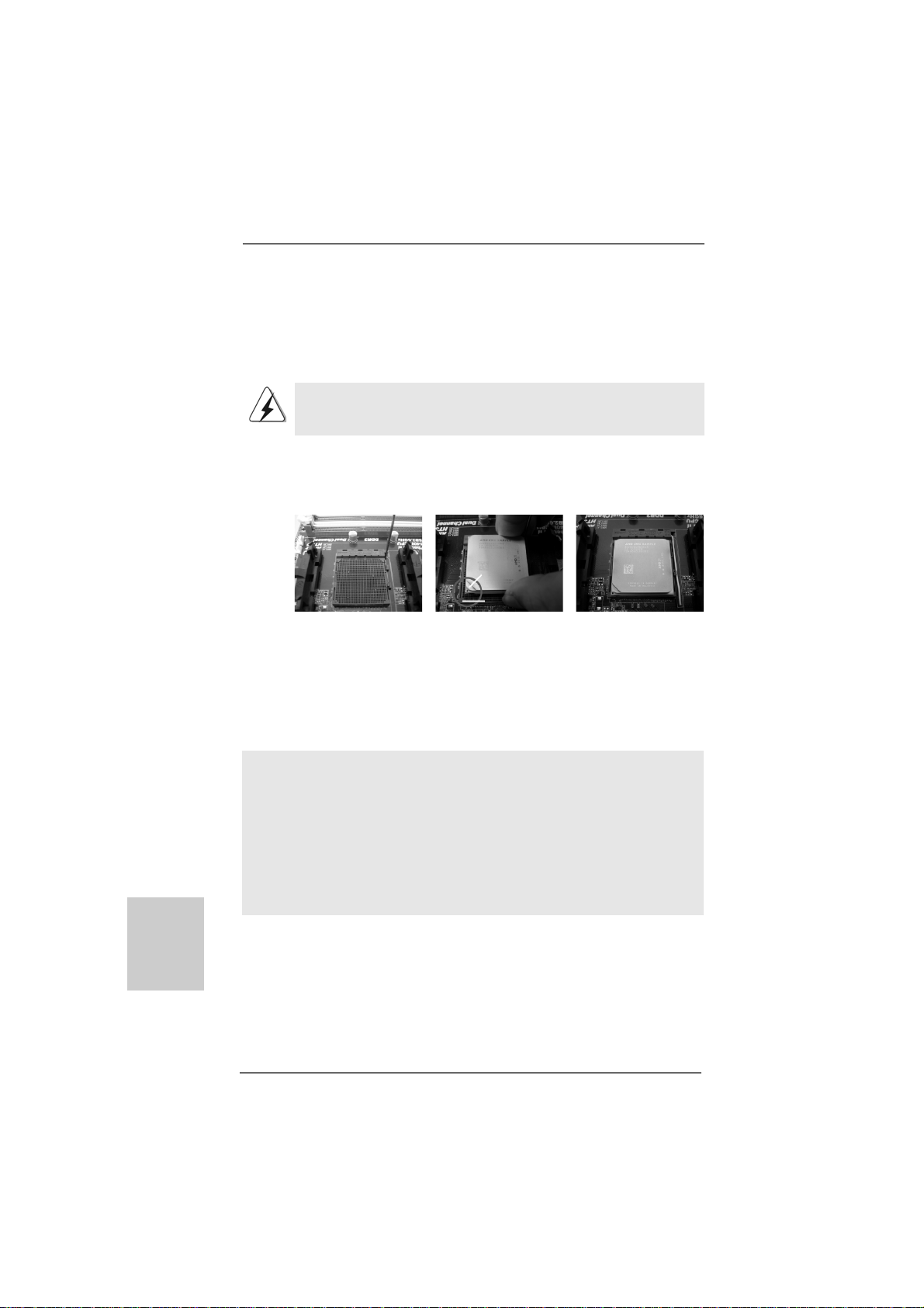
Step 1. Unlock the socket by lifting the lever up to a 90
o
angle.
Step 2. Position the CPU directly above the socket such that the CPU corner with
the golden triangle matches the socket corner with a small triangle.
Step 3. Carefully insert the CPU into the socket until it fits in place.
The CPU fits only in one correct orientation. DO NOT force the CPU
into the socket to avoid bending of the pins.
Step 4. When the CPU is in place, press it firmly on the socket while you push
down the socket lever to secure the CPU. The lever clicks on the side tab
to indicate that it is locked.
Lever 90° Up
CPU Golden Triangle
Socker Corner
Small Triangle
STEP 1:
Lift Up The Socket Lever
2.22.2
Installation of CPU Fan and HeatsinkInstallation of CPU Fan and Heatsink
2.2
Installation of CPU Fan and Heatsink
2.22.2
Installation of CPU Fan and HeatsinkInstallation of CPU Fan and Heatsink
STEP 2 / STEP 3:
Match The CPU Golden Triangle
To The Socket Corner Small
Triangle
STEP 4:
Push Down And Lock
The Socket Lever
English
EnglishEnglish
EnglishEnglish
1212
12
1212
After you install the CPU into this motherboard, it is necessary to install a
larger heatsink and cooling fan to dissipate heat. You also need to spray
thermal grease between the CPU and the heatsink to improve heat
dissipation. Make sure that the CPU and the heatsink are securely fastened and in good contact with each other. Then connect the CPU fan to
the CPU FAN connector (CPU_FAN1, see Page 2, No. 3). For proper
installation, please kindly refer to the instruction manuals of the CPU fan
and the heatsink.
ASRock 960GM/U3S3 FX Motherboard
2.3 Installation of Memor2.3 Installation of Memor
2.3 Installation of Memor
2.3 Installation of Memor2.3 Installation of Memor
960GM/U3S3 FX motherboard provides two 240-pin DDR3 (Double Data Rate 3) DIMM
slots, and supports Dual Channel Memory Technology. For dual channel configuration,
you always need to install two identical (the same brand, speed, size and chip-type)
memory modules in the DD R3 DIMM slots to a ctivate Dual Channel Me mory Technology.
Otherwise, it will operate at single channel mode.
1. It is not allowed to install a DDR or DDR2 memory module into
DDR3 slot;otherwise, this motherboard and DIMM may be damaged.
2. If you install only one memory module or two non-identical memory
modules, it is unable to activate the Dual Cha nnel Memory Technology.
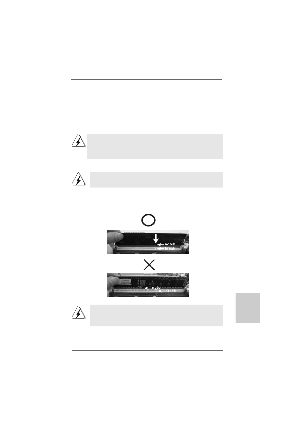
Installing a DIMMInstalling a DIMM
Installing a DIMM
Installing a DIMMInstalling a DIMM
Please make sure to disconnect power supply before adding or
removing DIMMs or the system components.
Step 1. Unlock a DIMM slot by pressing the retaining clips outward.
Step 2. Align a DIMM on the slot such that the notch on the DIMM matches the break
on the slot.
y Modules (DIMM)y Modules (DIMM)
y Modules (DIMM)
y Modules (DIMM)y Modules (DIMM)
The DIMM only fits in one correct orientation. It will cause permanent
damage to the motherboard and the DIMM if you force the DIMM into the
slot at incorrect orientation.
Step 3. Firmly insert the DIMM into the slot until the retaining clips at both ends fully
snap back in place and the DIMM is properly seated.
ASRock 960GM/U3S3 FX Motherboard
1313
13
1313
EnglishEnglish
EnglishEnglish
English

2.4 Expansion Slots (PCI and PCI Express Slots)2.4 Expansion Slots (PCI and PCI Express Slots)
2.4 Expansion Slots (PCI and PCI Express Slots)
2.4 Expansion Slots (PCI and PCI Express Slots)2.4 Expansion Slots (PCI and PCI Express Slots)
There is 1 PCI slot and 2 PCI Express slots on this motherboard.
PCI slots: PCI slots are used to install expansion cards that have the 32-bit PCI
interface.
PCIE slots:
PCIE1 (PCIE x1 slot; White) is used for PCI Express cards with x1 lan e
width cards, such as Gigabit LAN card, SATA2 card, etc.
PCIE2 (PCIE x16 slot; Blue) is used for PCI Express cards with x16 lane
width graphics cards.
Installing an expansion cardInstalling an expansion card
Installing an expansion card
Installing an expansion cardInstalling an expansion card
Step 1. Before installing the expansion card, please make sure that the power supply
is switched off or the power cord is unplugged. Please rea d the documentation
of the expansion card a nd ma ke necessary hardware
settings for the card before you start the installation.
Step 2. Remove the bracket facing the slot that you intend to use. Keep the screws
for later use.
Step 3. Align the card connector with the slot and press firmly until the card is com-
pletely seated on the slot.
Step 4. Fasten the card to the chassis with screws.
English
EnglishEnglish
EnglishEnglish
1414
14
1414
ASRock 960GM/U3S3 FX Motherboard
2.5 Dual Monitor and Surround Display Features2.5 Dual Monitor and Surround Display Features
2.5 Dual Monitor and Surround Display Features
2.5 Dual Monitor and Surround Display Features2.5 Dual Monitor and Surround Display Features
Dual Monitor Feature
This motherboard supports dual monitor feature. With the internal dual VGA output
support (DVI-D and D-Sub), you ca n e asily enjoy the benefits of dual monitor feature
without installing any add-on VGA card to this motherboard. This motherboard also
provides independent display controllers for DVI-D a nd D-Sub to support dual VGA
output so that DVI-D a nd D-sub can drive same or different display contents.
To enable dual monitor feature, please follow the below steps:
1. Connect the DVI-D monitor cable to the DVI-D port on the I/O pa nel. And connect
the D-Sub monitor cable to the D-Sub port on the I/O panel.
D-Sub port DVI-D port
2. If you have installed onboard V G A driver from our support CD to your system
already, you can freely enjoy the benefits of dual monitor function after your
system boots. If you haven’t installed onboard VGA driver yet, please install
onboard V G A driver from our support CD to your system and restart your
computer. Then you can start to use dual monitor function on this motherboard.
When you playback HDCP-protected video from Blu-ray (BD) or
HD-DVD disc, the content will be displayed only in one of the two
monitors instead of both monitors.
Surround Display Feature
This motherboard supports surround display upgrade. With the internal dual VGA
output support (DVI-D and D-Sub) and the external add-on PCI Express VGA card, you
can easily enjoy the benefits of surround display feature.
Please refer to the f ollowing steps to set up a surround display environ ment:
1. Install the ATI
proper expansion card installation procedures for details.
2. Connect the DVI-D monitor cable to the DVI-D port on the I/O pa nel. And connect
the D-Sub monitor cable to the D-Sub port on the I/O panel. Connect the other
DVI-D monitor cable and D-Sub monitor cable to the corresponding connectors of
the add-on PCI Express VGA card on PCIE2 slot.
TM
PCI Express V G A card on PCIE2 slot. Please refer to page 14 for
ASRock 960GM/U3S3 FX Motherboard
1515
15
1515
EnglishEnglish
EnglishEnglish
English

English
EnglishEnglish
EnglishEnglish
3. Boot your system. Press <F2> or <Del> to enter BIOS setup. Enter “Share
Memory” option to adjust the memory capability to [32MB], [64MB], [128MB]
[256MB] or [512MB] to enable the function of D-sub. Ple ase ma ke sure that the
value you select is less than the total capability of the system memory. If you do
not adjust the BIOS setup, the default value of “Share Memory”, [Auto], will disable
D-Sub function when the add-on VGA card is inserted to this motherboard.
4. Install the onboard V G A driver and the add-on PCI Express VGA card driver to
your system. If you have installed the drivers already, there is no need to install
them again.
5. Set up a multi-monitor display.
For Windows® XP / XP 64-bit OS:
Right click the desktop, choose “Properties”, and select the “Settings” tab
so that you can adjust the parameters of the multi-monitor according to the
steps below.
A. Click the “Identify” button to display a large number on each monitor.
B. Right-click the display icon in the Display Properties di alog that you wish
to be your primary monitor, and then select “Primary”. When you use
multiple monitors with your card, one monitor will always be Primary,
and all additional monitors will be designated as Secondary.
C. Select the display icon identified by the number 2.
D. Click “Extend my Windows desktop onto this monitor”.
E. Right-click the display icon and select “Attached”, if necessary.
F. Set the “Screen Resolution” and “Color Quality” as a ppropri ate for the
second monitor. Click “Apply” or “OK” to apply these new values.
G. Repeat steps C through E for the diaplay icon identified by the number
one, two, three and four.
For Windows® 7 / 7 64-bit / VistaTM / VistaTM 64-bit OS:
Right click the desktop, choose “Personalize”, and select the “Display
Settings” tab so that you can adjust the parameters of the multi-monitor
according to the steps below.
A. Click the number ”2” icon.
B. Click the items “This is my main monitor” and “Extend the desktop onto
this monitor”.
C. Click “OK” to save your change.
D. Repeat steps A through C for the display icon identified by the number
three and four.
6. Use Surround Display. Click and drag the display icons to positions representing
the physical setup of your monitors that you would like to use. The placement
of display icons determines how you move items from one monitor to another.
1616
16
1616
ASRock 960GM/U3S3 FX Motherboard

HDCP Function
HDCP function is supported on this motherboard. To use HDCP function
with this motherboard, you need to adopt the monitor that supports
HDCP function as well. Theref ore, you ca n en joy the superior display
quality with high-definition HDCP encryption contents. Plea se refer to
below instruction for more details about HDCP function.
What is HDCP?
HDCP stands for High-Ba ndwidth Digital Content Protection, a
specification developed by Intel® for protecting digital entertainment
content that uses the DVI interface. HDCP is a copy prote ction
scheme to eliminate the possibility of intercepting digital data
midstream between the video source, or transmitter - such as a
computer, DVD player or set-top box - and the digital display, or
receiver - such a s a monitor, television or projector . In other words,
HDCP specification is designed to protect the integrity of content as it
is being transmitted.
Products compatible with the HDCP scheme such a s DVD players,
satellite and cable HDTV set-top-boxes, as well a s few entertainment PCs requires a secure connection to a compliant display. Due
to the increase in manufacturers employing HDCP in their equi pment,
it is highly recommended that the HDTV or LCD monitor you purchase
is compatible.
ASRock 960GM/U3S3 FX Motherboard
1717
17
1717
EnglishEnglish
EnglishEnglish
English
2.62.6
ASRock Smart Remote Installation GuideASRock Smart Remote Installation Guide
2.6
ASRock Smart Remote Installation Guide
2.62.6
ASRock Smart Remote Installation GuideASRock Smart Remote Installation Guide
ASRock Smart Remote is only used for ASRock motherboard with CIR he a der. Plea se
refer to below procedures for the quick installation and usage of ASRock Smart Remote.
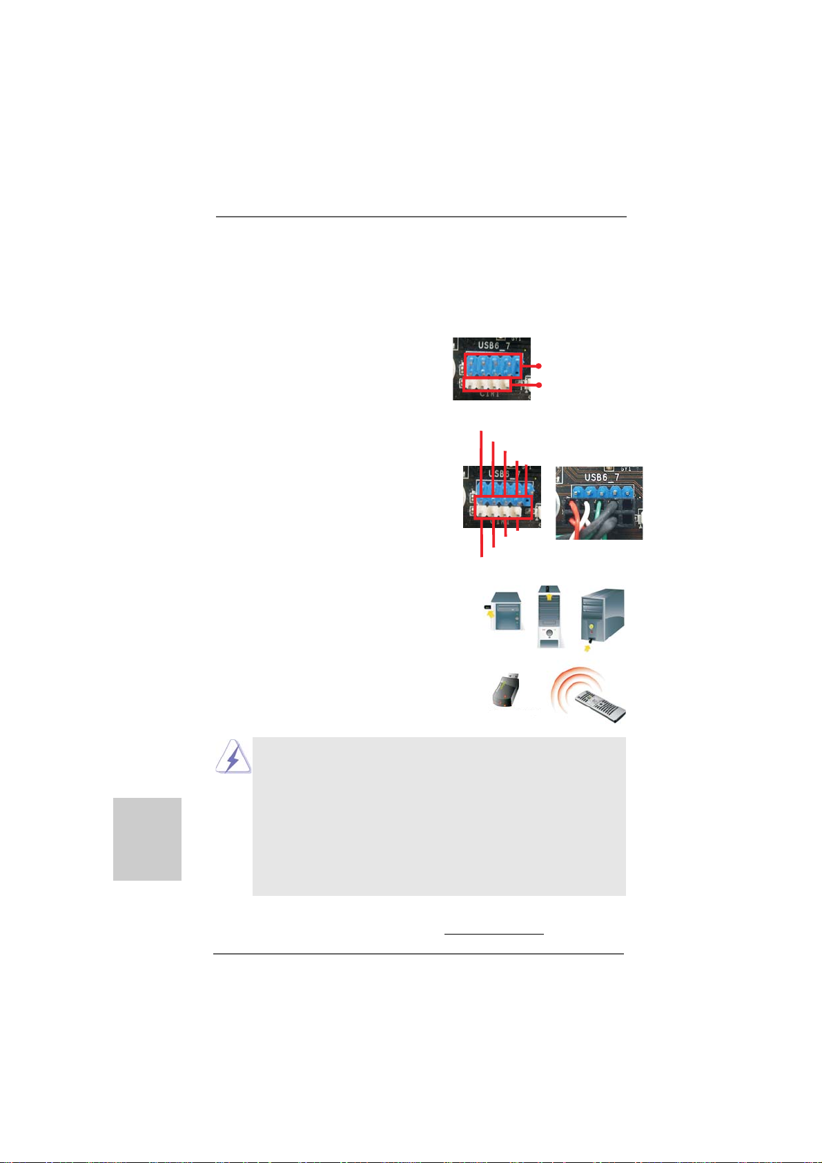
Step1. Find the CIR header located next to
the USB 2.0 header on ASRock
motherboard.
USB 2.0 header (9-pin, blue)
CIR header (4-pin, white)
English
EnglishEnglish
EnglishEnglish
Step2. Connect the front USB cable to the
USB 2.0 header (a s below, pin 1-5)
and the CIR header. Plea se
make sure the wire assignments and
the pin assignments are matched
correctly.
Step3. Install Multi-Angle CIR Receiver to
the front USB port. If Multi-Angle CIR
Receiver cannot success fully receive
the infrared signals from MCE
Remote Controller, please try to
install it to the other front USB port.
3 CIR sensors in different angles
1. Only one of the front USB port can support CIR function. When
the CIR function is enabled, the other port will remain USB
function.
2. Multi-Angle CIR Receiver is used for front USB only. Please do
not use the rear USB bracket to connect it on the rear panel.
Multi-Angle CIR Receiver can receive the multi-direction
infrared signals (top, down and front), which is compatible
with most of the chassis on the market.
3. The Multi-Angle CIR Receiver does not support Hot-Plug
function. Please install it before you boot the system.
USB_PWR
1
IRRX
ATX+5VSB
P-
P+
GND
DUMMY
3
2
5
4
GND
IRTX
* ASRock Smart Remote is only supported by some of ASRock motherboards. Please refer to
ASRock website for the motherboard support list:
1818
18
1818
http://www.asrock.com
ASRock 960GM/U3S3 FX Motherboard
2.72.7
Jumpers SetupJumpers Setup
2.7
Jumpers Setup
2.72.7
Jumpers SetupJumpers Setup
The illustration shows how jumpers are setup.
When the jumper cap is placed on pins, the
jumper is “Short”. If no jumper cap is pla ced on
pins, the jumper is “Open”. The illustration
shows a 3-pin jumper whose pin1 and
pin2 are “Short” when jumper cap is pla ced on
these 2 pins.
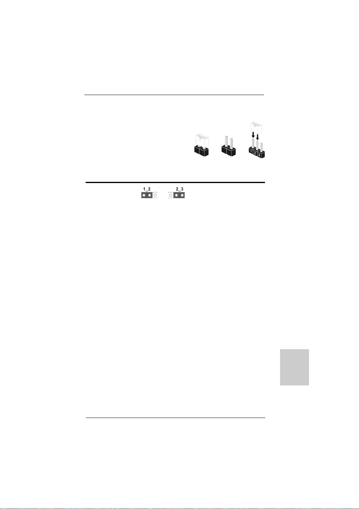
Jumper Setting
Clear CMOS Jumper
(CLRCMOS1)
(see p.2, No. 24)
Note: CLRCMOS1 allows you to clear the data in CMOS. The data in CMOS includes
system setup information such as system password, date, time, and system
setup parameters. To clear and reset the system parameters to default setup,
please turn off the computer and unplug the power cord from the power supply.
After waiting for 15 seconds, use a jumper ca p to short pin2 and pin3 on CLRCMOS1
for 5 seconds. However, ple a se do not cle ar the CMOS right after you update the
BIOS. If you need to clear the CMOS when you just finish updating the BIOS, you
must boot up the system first, and then shut it down before you do the clearCMOS action.
Clear CMOSDefault
OpenShort
ASRock 960GM/U3S3 FX Motherboard
1919
19
1919
EnglishEnglish
EnglishEnglish
English
2.8 Onboard Headers and Connectors2.8 Onboard Headers and Connectors
2.8 Onboard Headers and Connectors
2.8 Onboard Headers and Connectors2.8 Onboard Headers and Connectors
Onboard headers and connectors are NOT jumpers. Do NOT place
jumper caps over these headers and connectors. Placing jumper
caps over the headers and connectors will cause permanent damage of the motherboard!
•
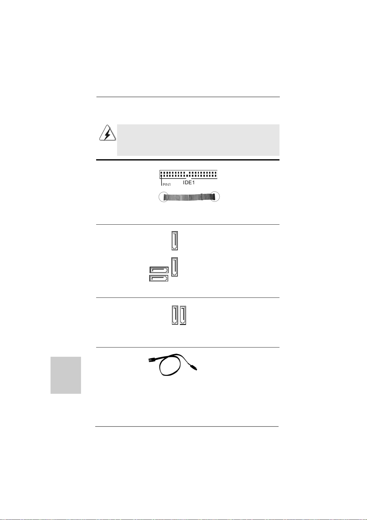
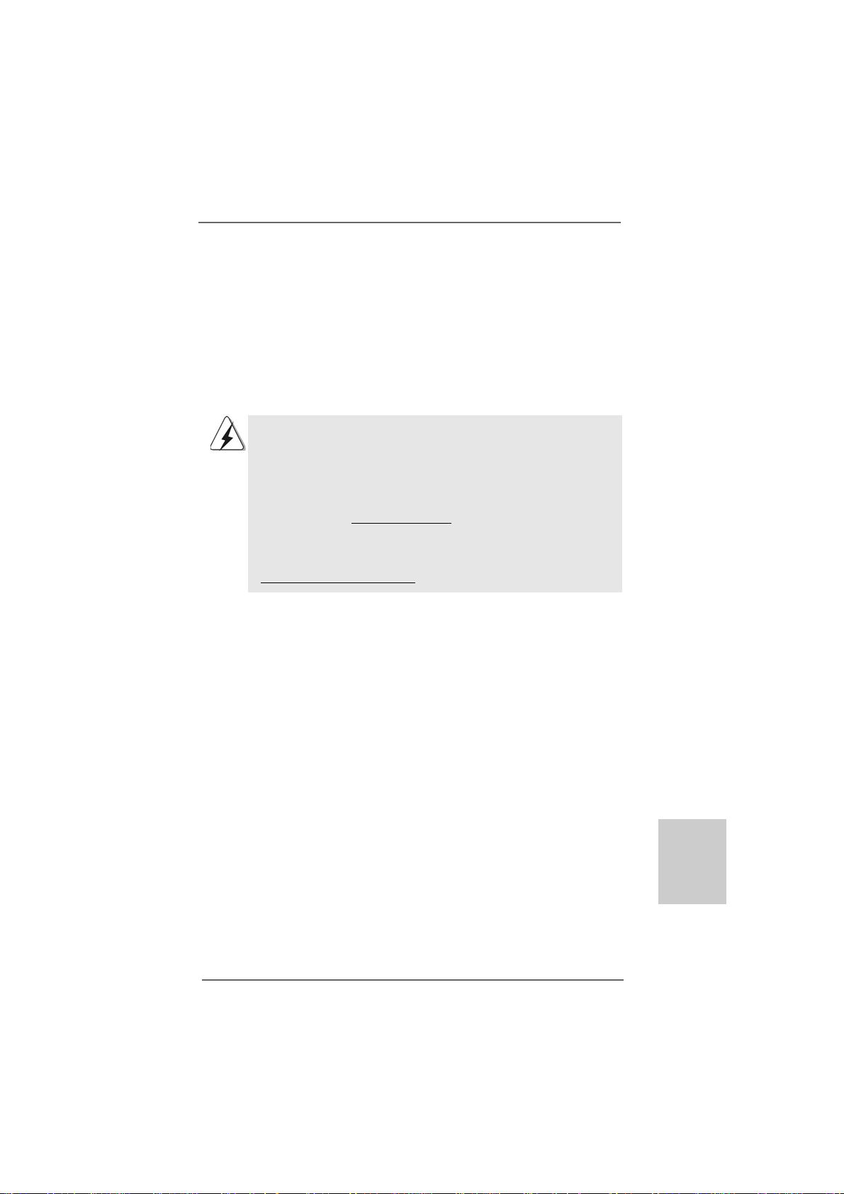
Primary IDE connector (Blue)
(39-pin IDE1, see p.2 No. 8)
English
EnglishEnglish
EnglishEnglish
connect the blue end
to the motherboard
connect the black end
to the IDE devices
80-conductor AT A 66/100/133 ca ble
Note: Please refer to the instruction of your IDE device vendor for the details.
Serial A TAII Connectors These four Serial AT AII (SA TAII)
(SATAII_1 (PORT 0): connectors support SATAII
see p.2, No. 15) or SATA hard disk f or internal
(SATAII_2 (PORT 1): storage devices. The current
see p.2, No. 14) SA TAII interface allows up to
(SATAII_3 (PORT 2): 3.0 Gb/s data tra n s fer rate.
see p.2, No. 13)
(SATAII_4 (PORT 3):
see p.2, No. 9)
SATAII_1
(PORT 0)
SATAII_2
(PORT 1)
SATAII_4
(PORT 3)
SATAII_3
(PORT 2)
Serial AT A3 Conne ctors These two Serial ATA3
(SATA3_1: see p.2, No. 11) (SATA3) connectors support
(SATA3_2: see p.2, No. 10) SATA data cables for internal
SATA3_1 SATA3_2
storage devices. The current
SATA3 interfa ce allows up to
6.0 Gb/s data tra n s fer rate.
Serial A TA (SA T A) Either end of the SATA data cable
Data Cable can be connected to the SAT AII /
(Optional) SATA3 hard disk or the SAT AII /
SATA3 connector on this
motherboard.
2020
20
2020
ASRock 960GM/U3S3 FX Motherboard
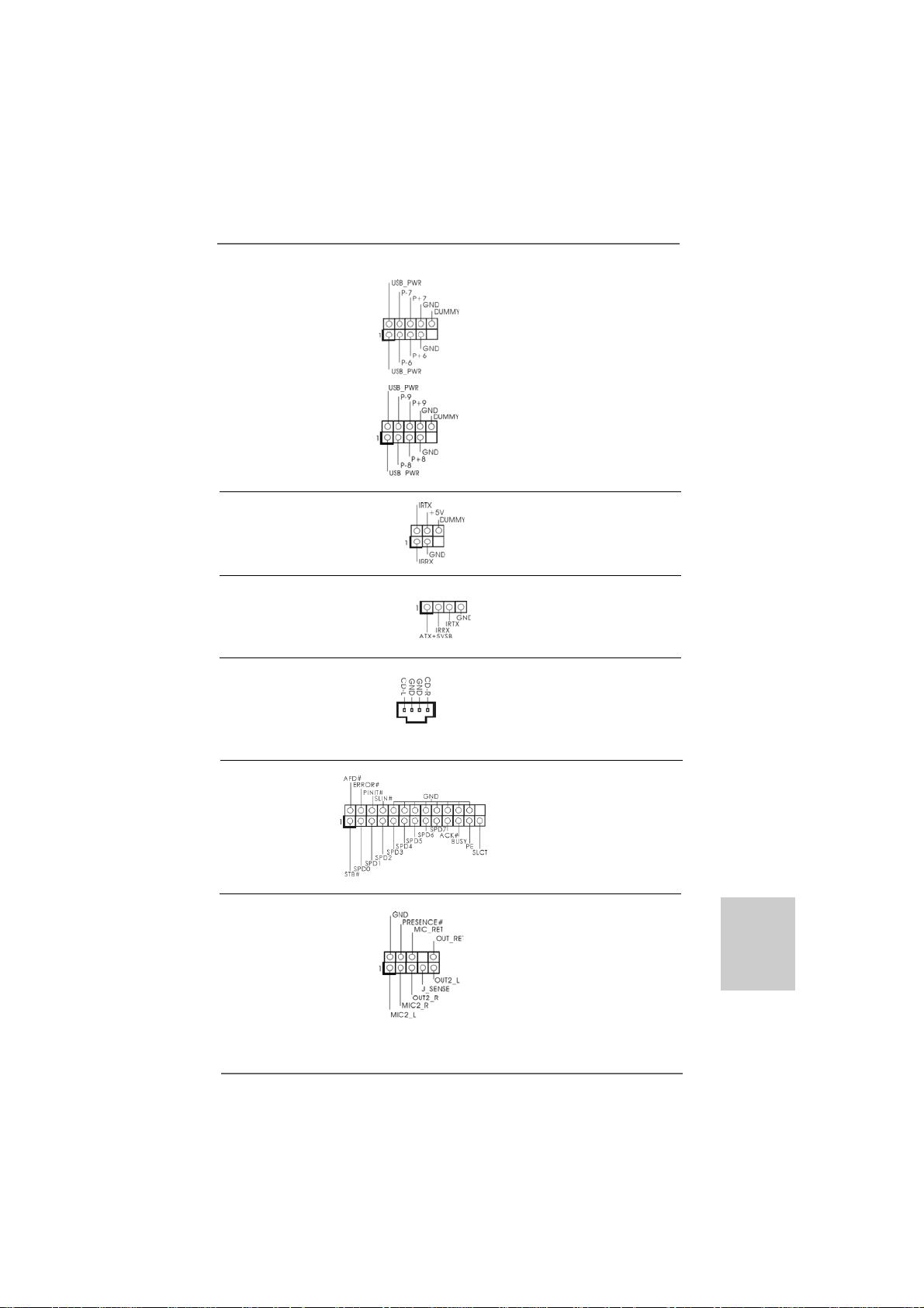
USB 2.0 Headers Besides four default USB 2.0
(9-pin USB6_7) ports on the I/O panel, there are
(see p.2 No. 21) two USB 2.0 headers on this
motherboard. Each USB 2.0
header can support two USB
2.0 ports.
(9-pin USB8_9)
(see p.2 No. 20)
Infrared Module Header This header supports an
(5-pin IR1) optional wireless transmitting
(see p.2 No. 23) and receiving infrared module.
Consumer Infrared Module Header This header can be used to
(4-pin CIR1) connect the remote
(see p.2 No. 22) controller receiver.
Internal Audio Connectors This connector allows you
(4-pin CD1) to receive stereo audio input
(CD1: see p.2 No. 26) from sound sources such as
CD1
a CD-ROM, DV D-ROM, TV
tuner card, or MPEG card.
Print Port Header This is an interfa ce for print
(25-pin LPT1) port cable that allows
(see p.2 No. 25) convenient connection of printer
devices.
Front Panel Audio Hea der This is an interface f or the front
(9-pin HD_AUDIO1) panel audio cable that allows
(see p.2, No. 27) convenient connection and
control of audio devices.
ASRock 960GM/U3S3 FX Motherboard
2121
21
2121
EnglishEnglish
EnglishEnglish
English
1. High Definition Audio supports Jack Sensing, but the panel wire on
the chassis must support HDA to function correctly. Please follow the
instruction in our manual and chassis manual to install your system.
2. If you use AC’97 audio panel, please install it to the front panel audio
header as below:
A. Connect Mic_IN (MIC) to MIC2_L.
B. Connect Audio_R (RIN) to OUT2_R and Audio_L (LIN) to OUT2_L.
C. Connect Ground (GND) to Ground (GND).
D. MIC_RET and OUT_RET are for HD audio panel only. You don’t
need to connect them for AC’97 audio panel.
E. To activate the front mic.
For Windows® XP / XP 64-bit OS:
Select “Mixer”. Select “Recorder”. Then click “FrontMic”.
For Windows® 7 / 7 64-bit / VistaTM / VistaTM 64-bit OS:
Go to the "FrontMic" Tab in the Realtek Control panel. Adjust
“Recording Volume”.
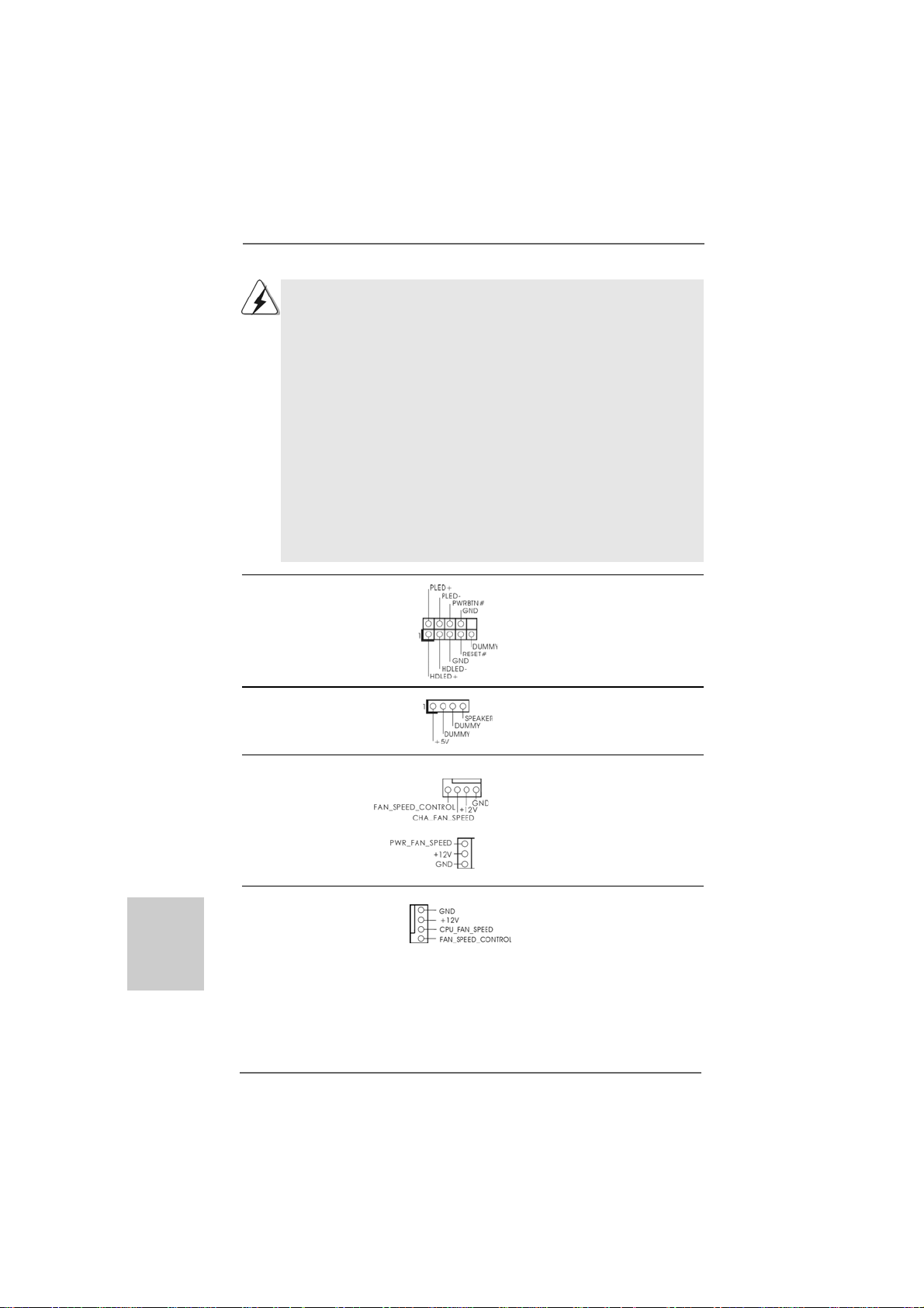
System Panel Header This header a ccommodates
(9-pin PANEL1) several system front panel
(see p.2 No. 17) functions.
Chassis Spea ker Hea der Please connect the chassis
(4-pin SPEAKER 1) speaker to this header.
(see p.2 No. 16)
English
EnglishEnglish
EnglishEnglish
2222
22
2222
Chassis a nd Power Fa n Conne ctors Please connect the fan cables
(4-pin CHA_FAN1) to the fan connectors a nd
(see p.2 No. 18) match the black wire to the
(3-pin PWR_FAN1)
(see p.2 No. 7)
CPU Fan Connector Please connect the CPU fan
(4-pin CPU_FAN1) cable to this connector and
(see p.2 No. 5) match the black wire to the
1
2
3
4
ground pin.
ASRock 960GM/U3S3 FX Motherboard
Though this motherboard provides 4-Pin CPU fan (Quiet Fan) support, the 3-Pin
CPU fan still can work successfully even without the fan speed control function.
If you plan to connect the 3-Pin CPU fan to the CPU fan connector on this
motherboard, please connect it to Pin 1-3.
Pin 1-3 Connected
3-Pin Fan Installation
ATX Power Conne ctor Plea se connect an A TX power
(24-pin ATXPWR1) supply to this connector.
(see p.2 No. 6)
Though this motherboard provides 24-pin ATX power connector,
it can still work if you adopt a traditional 20-pin ATX power supply.
12 124
13
12
To use the 20-pin ATX power supply, please plug your power
supply along with Pin 1 and Pin 13.
20-Pin ATX Power Supply Installation
1
ATX 12V Power Connector Please connect an ATX 12V
(4-pin A TX12V1) power supply to this connector.
(see p.2 No. 1)
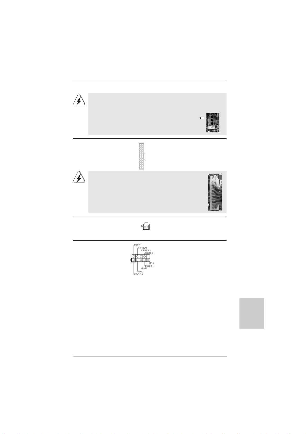
Serial port Header This COM1 header supports a
(9-pin COM1) serial port module.
(see p.2 No. 29)
24
13
ASRock 960GM/U3S3 FX Motherboard
2323
23
2323
EnglishEnglish
EnglishEnglish
English

2.92.9
Driver Installation GuideDriver Installation Guide
2.9
Driver Installation Guide
2.92.9
Driver Installation GuideDriver Installation Guide
To install the drivers to your system, please insert the support CD to your optical drive
first. Then, the drivers compatible to your system can be auto-detected and listed on
the support CD driver page. Please follow the order from up to bottom side to install
those required drivers. Therefore, the drivers you install can work properly.
English
EnglishEnglish
EnglishEnglish
®®
®
2.102.10
Installing WindowsInstalling Windows
2.10
Installing Windows
2.102.10
Installing WindowsInstalling Windows
TMTM
TM
TMTM
VistaVista
Vista
VistaVista
If you want to install Windows® 7 / 7 64-bit / VistaTM / VistaTM 64-bit / XP / XP 64-bit on
your SATA / SATA2 HDDs with RAID functions, please refer to the document at the
following path in the Support CD for detailed procedures:
..\ RAID Installation Guide
2.112.11
Installing WindowsInstalling Windows
2.11
Installing Windows
2.112.11
Installing WindowsInstalling Windows
VistaVista
Vista
VistaVista
If you want to install Windows® 7 / 7 64-bit / VistaTM / VistaTM 64-bit / XP / XP 64-bit OS
on your SATA / SATA2 / SATA3 HDDs without RAID functions, please follow below
procedures according to the OS you install.
2.11.1 Installing Windows2.11.1 Installing Windows
2.11.1 Installing Windows
2.11.1 Installing Windows2.11.1 Installing Windows
F F
F
F F
If you want to install Windows® XP / XP 64-bit on your SATA / SATA2 / SATA3 HDDs
without RAID functions, please follow below steps.
Using SATA / SATA2 / SATA3 HDDs without NCQ and Hot Plug functions (IDE
mode)
STEP 1: Set up BIOS.
A. Enter BIOS SETUP UTILITY Advanced screen Storage
Configuration.
B. Set the “SATA Operation Mode” option to [IDE] for SAT AII_1 to SA TAII_4 ports.
Set the “Onboard SATA3 Operation Mode” option to [IDE] for SAT A3_1 and
SATA3_2 ports.
STEP 2: Install Windows® XP / XP 64-bit OS on your system.
64-bit / XP / XP 64-bit W 64-bit / XP / XP 64-bit W
64-bit / XP / XP 64-bit W
64-bit / XP / XP 64-bit W 64-bit / XP / XP 64-bit W
TMTM
TM
TMTM
64-bit / XP / XP 64-bit W 64-bit / XP / XP 64-bit W
64-bit / XP / XP 64-bit W
64-bit / XP / XP 64-bit W 64-bit / XP / XP 64-bit W
unctionsunctions
unctions
unctionsunctions
®®
7 / 7 64-bit / Vista 7 / 7 64-bit / Vista
7 / 7 64-bit / Vista
7 / 7 64-bit / Vista 7 / 7 64-bit / Vista
ith RAID Fith RAID F
ith RAID F
ith RAID Fith RAID F
®®
®
®®
7 / 7 64-bit / Vista 7 / 7 64-bit / Vista
7 / 7 64-bit / Vista
7 / 7 64-bit / Vista 7 / 7 64-bit / Vista
ithout RAID Fithout RAID F
ithout RAID F
ithout RAID Fithout RAID F
®®
®
®®
XP / XP 64-bit Without RAID XP / XP 64-bit Without RAID
XP / XP 64-bit Without RAID
XP / XP 64-bit Without RAID XP / XP 64-bit Without RAID
TMTM
TM
TMTM
/ /
/
/ /
unctionsunctions
unctions
unctionsunctions
TMTM
TM
TMTM
/ /
/
/ /
unctionsunctions
unctions
unctionsunctions
2424
24
2424
ASRock 960GM/U3S3 FX Motherboard
®®
®
2.11.2 Installing Windows2.11.2 Installing Windows
2.11.2 Installing Windows
2.11.2 Installing Windows2.11.2 Installing Windows
TMTM
TM
Vista Vista
Vista
Vista Vista
If you want to install Windows® 7 / 7 64-bit / VistaTM / VistaTM 64-bit on your SATA /
SA TA2 / SA TA3 HDDs without RAID functions, ple ase follow below steps.
Using SATA / SATA2 / SATA3 HDDs without NCQ and Hot Plug functions (IDE
mode)
STEP 1: Set up BIOS.
A. Enter BIOS SETUP UTILITY Advanced screen Storage
Configuration.
B. Set the “SATA Operation Mode” option to [IDE] for SAT AII_1 to SA TAII_4 ports.
Set the “Onboard SATA3 Operation Mode” option to [IDE] for SAT A3_1 and
SATA3_2 ports.
STEP 2: Install Windows
system.
Using SATA / SAT A2 / SAT A3 HDDs with NCQ a nd Hot Plug functions (AHCI mode)
STEP 1: Set Up BIOS.
A. Enter BIOS SETUP UTILITY Advanced screen Storage
Configuration.
B. Set the “SA TA Operation Mode” option to [AHCI] for SATAII_1 to SATAII_4
ports.
Set the “Onboard SATA3 Operation Mode” option to [AHCI] for SAT A3_1 a n d
SATA3_2 ports.
STEP 2: Install Windows
system.
TMTM
64-bit W 64-bit W
64-bit W
64-bit W 64-bit W
®
7 / 7 64-bit / VistaTM / VistaTM 64-bit OS on your
®
7 / 7 64-bit / VistaTM / VistaTM 64-bit OS on your
®®
7 / 7 64-bit / Vista 7 / 7 64-bit / Vista
7 / 7 64-bit / Vista
7 / 7 64-bit / Vista 7 / 7 64-bit / Vista
ithout RAID Fithout RAID F
ithout RAID F
ithout RAID Fithout RAID F
unctionsunctions
unctions
unctionsunctions
TMTM
TM
TMTM
/ /
/
/ /
2.122.12
Untied Overclocking TUntied Overclocking T
2.12
Untied Overclocking T
2.122.12
Untied Overclocking TUntied Overclocking T
This motherboard supports Untied Overclocking Technology, which means during
overclocking, FSB enjoys better margin due to fixed PCI / PCIE buses. Before you
enable Untied Overclocking function, plea se enter “Overclock Mode” option of BIOS setup
to set the selection from [Auto] to [Manual]. Therefore, CPU FSB is untied during
overclocking, but PCI / PCIE buses are in the fixed mode so that FSB can operate under
a more stable overclocking environment.
Please refer to the warning on page 7 for the possible overclocking risk
before you apply Untied Overclocking Technology.
ASRock 960GM/U3S3 FX Motherboard
echnologyechnology
echnology
echnologyechnology
2525
25
2525
EnglishEnglish
EnglishEnglish
English

3. BIOS Information3. BIOS Information
3. BIOS Information
3. BIOS Information3. BIOS Information
The Flash Memory on the motherboard stores BIOS Setup Utility. When you start up
the computer, please press <F2> during the Power-On-Self-Test (POST) to enter
BIOS Setup utility; otherwise, POST continues with its test routines. If you wish to
enter BIOS Setup after POST, please restart the system by pressing <Ctl> + <Alt> +
<Delete>, or pressing the reset button on the system chassis. The BIOS Setup
program is designed to be user-friendly. It is a menu-driven program, which allows
you to scroll through its various sub-menus and to select among the predetermined
choices. For the detailed information about BIOS Setup, please refer to the User
Manual (PDF file) contained in the Support CD.
English
EnglishEnglish
EnglishEnglish
4. Sof4. Sof
4. Sof
4. Sof4. Sof
This motherboard supports various Microsoft® Windows® operating systems: 7 / 7
64-bit / VistaTM / VistaTM 64-bit / XP / XP Media Center / XP 64-bit. The Support CD that
came with the motherboard contains necessary drivers and useful utilities that will
enhance motherboard features. To begin using the Support CD, insert the CD into
your CD-ROM drive. It will display the Main Menu automatically if “AUTORUN” is
enabled in your computer . If the Main Menu does not appear automatically, locate and
double-click on the file “ASSETUP.EXE” from the “BIN” folder in the Support CD to
display the menus.
tware Supportware Suppor
tware Suppor
tware Supportware Suppor
t CD informationt CD information
t CD information
t CD informationt CD information
2626
26
2626
ASRock 960GM/U3S3 FX Motherboard
1. Einführung1. Einführung
1. Einführung
1. Einführung1. Einführung
Wir danken Ihnen für den Kauf des ASRock 960GM/U3S3 FX Motherboard, ein
zuverlässiges Produkt, welches unter den ständigen, strengen Qualitätskontrollen von
ASRock gefertigt wurde. Es bietet Ihnen exzellente Leistung und robustes De sign, gemäß
der Verp flichtung von ASRock zu Qualität und Halbarkeit.
Diese Schnellinstallationsanleitung führt in das Motherboard und die schrittweise
Installation ein. Details über das Motherboard finden Sie in der
Bedienungsanleitung auf der Support-CD.
Da sich Motherboard-Spezifikationen und BIOS-Software verändern
können, kann der Inhalt dieses Handbuches ebenfalls jederzeit geändert
werden. Für den Fall, dass sich Änderungen an diesem Handbuch
ergeben, wird eine neue Version auf der ASRock-Website, ohne weitere
Ankündigung, verfügbar sein. Die neuesten Grafikkarten und unterstützten
CPUs sind auch auf der ASRock-Website aufgelistet.
ASRock-Website: http://www.asrock.com
Wenn Sie technische Unterstützung zu Ihrem Motherboard oder spezifische
Informationen zu Ihrem Modell benötigen, besuchen Sie bitte unsere
Webseite:
www.asrock.com/support/index.asp
1.1 Kartoninhalt
ASRock 960GM/U3S3 FX Motherboard
(Micro ATX-Formfa ktor: 24.4 cm x 19.8 cm; 9.6 Zoll x 7.8 Zoll)
ASRock 960GM/U3S3 FX Schnellinstallationsanleitung
ASRock 960GM/U3S3 FX Support-CD
Zwei Seriell-ATA- (SATA) Datenkabel (Option)
Ein I/O Shield
ASRock 960GM/U3S3 FX Motherboard
2727
27
2727
DeutschDeutsch
DeutschDeutsch
Deutsch
Deutsch
DeutschDeutsch
DeutschDeutsch
1.21.2
SpezifikationenSpezifikationen
1.2
Spezifikationen
1.21.2
SpezifikationenSpezifikationen
Plattform - Micro ATX-Formfaktor: 24.4 cm x 19.8 cm; 9.6 Zoll x 7.8 Zoll
- Festkondensator für CPU-Leistung
CPU - Unterstützung von Socket AM3+-Prozessoren
- Unterstützung von Socket AM3-Proze ssoren: AMD Phenom
II X6 / X4 / X3 / X2 (außer 920 / 940) / Athlon X4 / X3 / X2 /
Sempron-Prozessor
- Acht-Kern-CPU-bereit
- Unterstützt AMD OverDriveTM mit ACC-Funktion (Advanced
Clock Calibration, Erweiterte Taktkalibrierung)
- AMD LIVE!TM-bereit
- Unterstützt Cool ‘n’ QuietTM-T e chnologie von AM D
- FSB 2600 MHz (5.2 GT/s)
- Unterstützt U ntied-Überta ktungstechnologie
(siehe VORSICHT 1)
- Unterstützt Hyper-Transport- 3.0 Technologie (HT 3.0)
Chipsatz - Northbridge: AMD 760G
- Southbridge: AMD 710
Speicher - Unterstützung von Dual-Kan al-Speichertechnologie
(siehe VORSICHT 2)
- 2 x Steckplätze für DDR3
- Unterstützt DDR3 1866(OC)/1600(OC)/1333/1066/800
non-ECC, ungepufferter Speicher (siehe VORSICHT 3)
- Max. Kapazität des Systemspeichers: 16GB
(siehe VORSICHT 4)
Erweiterungs- - 1 x PCI Express 2.0 x16-Steckplatz (blau für x16-Modus)
steckplätze - 1 x PCI Express 2.0 x1-Steckplatz
- 1 x PCI -Steckplatz
Onboard-VGA - Integrierte AMD Radeon HD 3000-Grafik
- D X10 Klasse iGPU, Pixel Shader 4.0
- Maximal gemeinsam genutzter Speicher 512 MB
(siehe VORSICHT 5)
- Doppel-VGA Ausga be: unterstützt D VI-D und D-Sub Ports
durch unabhängige Bildschirmanzeige Kontrolleure
- Unterstützt DVI mit einer maximalen Auflösung von bis zu
1920x1200 bei 75 Hz
- Unterstützt D-Sub mit einer maximalen Auflösung von
2048 x 1536 bei 85 Hz
- unterstützt HDCP Funktion mit DVI-D Port
TM
2828
28
2828
ASRock 960GM/U3S3 FX Motherboard
- Unterstutzt 1080p Blu-ray (BD) / HD-DV D-Wiedergabe mit
DVI-D Port
Audio - 5.1 CH HD Audio (Realtek ALC662 Audio Codec)
LAN - PCIE x1 Gigabit LAN 10/100/1000 Mb/s
- Realtek RTL81 1 1E
- Unterstützt W ake-On-LAN
- Unterstützt LAN-Kabelerkennung
- Unterstützt energieeffizientes Ethernet 802.3az
- Unterstützt PXE
E/A-Anschlüsse I/O Panel
an der - 1 x PS/2 Mouse Port
Rückseite - 1 x PS/2 Keyboard Port
- 1 x D-Sub port
- 1 x DVI-D port
- 4 x Standard-USB 2.0-Anschlüsse
- 2 x Standard-USB 3.0-Anschlüsse
- 1 x RJ-45 LAN Port mit LED (ACT/LINK LED und SPEED LED)
- HD Audiobuchse: Audioeinga ng / Lautspre cher vorne /
Mikrofon
SATA3 - 2 x ASMedia ASM1061 SAT A 3-Anschlüsse (6,0 Gb/s);
unterstützt NCQ-, AHCI- und „Hot Plug“ (Hot-Plugging) Funktionen
USB 3.0 - 2 x USB 3.0-Ports durch Etron EJ168A; unterstützt
USB 1.0/2.0/3.0 mit bis zu 5 Gb/s
Anschlüsse - 4 x SATA2-Anschlüsse, unterstützt bis 3.0 Gb/s
Datenübertragungsrate, unterstützt RAID (RAID 0, RAID 1,
RAID 10 und JBOD), NCQ, AHCI und “Hot Plug” Funktionen
(siehe VORSICHT 6)
- 2 x SATA3 6,0 GB/s-Anschlüsse
- 1 x ATA133 IDE-Anschlüsse (Unterstützt bis 2 IDE-Geräte)
- 1 x Infrarot-Modul-Header
- 1 x Consumer Infrared-Modul-Header
- 1 x Druckerport-Anschlussleiste
- 1 x COM-Anschluss-Header
- CPU/Gehäuse/Strom-Lüfteranschluss
- 24-pin A TX-Netz-Header
- 4-pin anschluss für 12V -ATX-Netzteil
- Interne Audio-Anschlüsse
- Anschluss für Audio auf der Gehäusevorderseite
- 2 x USB 2.0-Anschlüsse (Unterstützung 4 zusätzlicher
USB 2.0-Anschlüsse)
DeutschDeutsch
DeutschDeutsch
Deutsch
ASRock 960GM/U3S3 FX Motherboard
2929
29
2929
Deutsch
DeutschDeutsch
DeutschDeutsch
3030
30
3030
BIOS - 8Mb AMI BIOS
- AMI legal BIOS mit U nterstützung für “Plug and Play”
- ACPI 1.1-Weckfunktionen
- JumperFree-Modus
- SMBIOS 2.3.1
- CPU, VCCM, NB Stromspa nnung Multianpa ssung
Support-CD - Treiber, Dienstprogra mme, Antivirussoftware
(Probeversion), AMD OverDriveTM-Dienstprogramm, CyberLink
MediaEspresso 6.5 Trial, Suite logicielle ASRock (CyberLink
DVD Suite et Version OEM et d’essai; ASRock MAGIX Multimedia-Suite - OEM)
Einzigartige - ASRock OC Tuner (siehe VORSICHT 7)
Eigenschaft - ASRock Intelligent Energy Saver (Intelligente
Energiesparfunktion) (siehe VORSICHT 8)
- ASRock Sofortstart
- ASRock Instant Flash (siehe VORSICHT 9)
- ASRock OC DNA (siehe VORSICHT 10)
- ASRock AP P Charger (siehe VORSICHT 1 1)
- ASRock SmartView (siehe VORSICHT 12)
- ASRock XFast USB (siehe VORSICHT 13)
- ASRock XFast LAN (siehe VORSICHT 14)
- ASRock XFast RAM (siehe VORSICHT 15)
- Hybrid Booster:
- Schrittloser CPU-Frequenz-Kontrolle
(siehe VORSICHT 16)
- ASRock U-COP (siehe VORSICHT 17)
- Boot Failure Guard (B.F.G. – Systemstartfehlerschutz)
Hardware Monitor - CPU-Te mperatursensor
- Motherboardtemperaturerkennung
- Drehzahlmessung für CPU/Gehäuse/Stromlüfter
- CPU-/Gehäuselüftergeräuschdämpfung
- Mehrstufige Geschwindigke itsteuerung für CPU-/
Gehäuselüfter
- Spannungsüberwachung: +12V, +5V, +3.3V, Vcore
Betriebssysteme - Unterstützt Microsoft® Windows® 7 / 7 64-Bit / VistaTM /
Zertifizierungen - FCC, CE, WHQL
* Für die ausführliche Produktinformation, besuchen Sie bitte unsere Website:
http://www.asrock.com
TM
Vista
64-Bit / XP / XP Media Center / XP 64-Bit
- Gemäß Ökodesign-Richtlinie (ErP/EuP) (Stromversorgung
gemäß Ökodesign-Richtlinie (ErP/EuP) erforderlich)
(siehe VORSICHT 18)
ASRock 960GM/U3S3 FX Motherboard

WAR NUNG
Beachten Sie bitte, dass Overclocking, einschließlich der Einstellung im BIOS, Anwenden
der Untied Overclocking-Technologie oder Verwenden von Overclocking-Werkzeugen von
Dritten, mit einem gewissen Risiko behaftet ist. Overclocking kann sich nachteilig auf die
Stabilität Ihres Systems auswirken oder sogar Komponenten und Geräte Ihres Systems
beschädigen. Es geschieht dann auf eigene Gefahr und auf Ihre Kosten. Wir übernehmen
keine Verantwortung für mögliche Schäden, die aufgrund von Overclocking verursacht
wurden.
VORSICHT!
1. Dieses Motherboard unterstützt die Untied-Übertaktungstechnologie.
Unter “Entkoppelte Übertaktungstechnologie” auf Seite 25 finden Sie
detaillierte Informationen.
2. Dieses Motherboard unterstützt Dual-Kanal-Speichertechnologie. Vor
Implementierung der Dual-Kanal-Speichertechnologie müssen Sie die
Installationsanleitung für die Speichermodule auf Seite 13 zwecks
richtigerInstallation gelesen haben.
3. Ob die Speichergeschwindigkeit 1866/1600 MHz unterstützt wird, hängt
von der von Ihnen eingesetzten AM3/AM3+-CPU ab. Schauen Sie bitte
auf unseren Internetseiten in der Liste mit unterstützten
Speichermodulen nach, wenn Sie DDR3 1866/1600-Speichermodule
einsetzen möchten.
ASRock-Internetseite: http://www.asrock.com
4. Durch Betriebssystem-Einschränkungen kann die tatsächliche
Speichergröße weniger als 4 GB betragen, da unter Windows® 7 / Vista™
/ XP etwas Speicher zur Nutzung durch das System reserviert wird.
Unter Windows® OS mit 64-Bit-CPU besteht diese Einschränkung nicht.
5. Die Maximalspeichergröße ist von den Chipshändler definiert und
umgetauscht. Bitte überprüfen Sie AMD website für die neuliche
Information.
6. Vor Installation der SATAII-Festplatte an den SATAII-Anschluss lesen
Sie bitte “Setup-Anleitung für SATAII-Festplatte” auf Seite 27 der
“Bedienungsanleitung” auf der Support-CD, um Ihre SATAII-Festplatte
dem SATAII-Modus anzugleichen. Sie können die SATA-Festplatte
auch direkt mit dem SATAII-Anschluss verbinden.
7. Es ist ein benutzerfreundlicher ASRock Übertaktenswerkzeug, das
erlaubt, dass Sie Ihr System durch den Hardware-Monitor Funktion zu
überblicken und Ihre Hardware-Geräte übertakten, um die beste
Systemleistung unter der Windows® Umgebung zu erreichen. Besuchen
Sie bitte unsere Website für die Operationsverfahren von ASRock OC
Tuner. ASRock-Website: http://www.asrock.com
8. Mit einer eigenen, modernen Hardware und speziellem Softwaredesign,
bietet der Intelligent Energy Saver eine revolutionäre Technologie zur
bisher unerreichten Energieeinsparung. Ein Spannungsregler kann
die Anzahl von Ausgangsphasen zur Effektivitätsverbessserung
reduzieren, wenn sich die CPU im Leerlauf befindet. Mit anderen
Worten: Sie genießen außergewöhnliche Energieeinsparung und
ASRock 960GM/U3S3 FX Motherboard
3131
31
3131
DeutschDeutsch
DeutschDeutsch
Deutsch

Deutsch
DeutschDeutsch
DeutschDeutsch
verbesserten Wirkungsgrad ohne Leistungseinschränkungen. Wenn
Sie die Intelligent Energy Saver-Funktion nutzen möchten, aktivieren
Sie zuvor die „Cool ‘n’ Quiet“-Option im BIOS. Weitere
Bedienungshinweise zum Intelligent Energy Saver finden Sie auf
unseren Internetseiten. ASRock-Internetseite: http://www.asrock.com
9. ASRock Instant Flash ist ein im Flash-ROM eingebettetes BIOS-Flash-
Programm. Mithilfe dieses praktischen BIOSAktualisierungswerkzeugs können Sie das System-BIOS
aktualisieren, ohne dafür zuerst Betriebssysteme wie MS-DOS oder
Windows® aufrufen zu müssen. Mit diesem Programm bekommen
Sie durch Drücken der <F6>-Taste während des POST-Vorgangs oder
durch Drücken der <F2>-Taste im BIOS-Setup-Menü Zugang zu
ASRock Instant Flash. Sie brauchen dieses Werkzeug einfach nur zu
starten und die neue BIOS-Datei auf Ihrem USB-Flash-Laufwerk,
Diskettenlaufwerk oder der Festplatte zu speichern, und schon
können Sie Ihr BIOS mit nur wenigen Klickvorgängen ohne
Bereitstellung einer zusätzlichen Diskette oder eines anderen
komplizierten Flash-Programms aktualisieren. Achten Sie darauf,
dass das USB-Flash-Laufwerk oder die Festplatte das Dateisystem
FAT32/16/12 benutzen muss.
10. Allein der Name – OC DNA* – beschreibt es wörtlich, was die
Software zu leisten vermag. OC DNA ist ein von ASRock exklusiv
entwickeltes Dienstprogramm, das Nutzern eine bequeme
Möglichkeit bietet, Übertaktungseinstellungen aufzuzeichnen und sie
Anderen mitzuteilen. Es hilft Ihnen, Ihre Übertaktungsaufzeichnung im
Betriebssystem zu speichern und vereinfacht den komplizierten
Aufzeichnungsvorgang von Übertaktungseinstellungen. Mit OC DNA
können Sie Ihre Übertaktungseinstellungen als Profil abspeichern
und Ihren Freunden zugänglich machen! Ihre Freunde können dann
das Übertaktungsprofil auf ihren eigenen Systemen laden, um
dieselben Übertaktungseinstellungen. Mit OC DNA können Sie Ihre
Übertaktungseinstellungen als Profil abspeichern und Ihren
Freunden zugänglich machen! Ihre Freunde können dann das
Übertaktungsprofil auf ihren eigenen Systemen laden, um dieselben
Übertaktungseinstellungen wie Sie zu erhalten! Beachten Sie bitte,
dass das Übertaktungsprofil nur bei einem identischen Motherboard
gemeinsam genutzt und funktionsfähig gemacht werden kann.
Übertaktungseinstellungen wie Sie zu erhalten! Beachten Sie bitte,
dass das Übertaktungsprofil nur bei einem identischen Motherboard
gemeinsam genutzt und funktionsfähig gemacht werden kann.
11. Wenn Sie nach einer schnelleren, weniger eingeschränkten
Möglichkeit zur Aufladung Ihrer Apple-Geräte (z. B. iPhone/iPad/iPod
touch) suchen, bietet ASRock Ihnen eine wunderbare Lösung – den
ASRock APP Charger. Installieren Sie einfach den ASRock APP
Charger-Treiber; dadurch lädt sich Ihr iPhone wesentlich schneller
über einen Computer auf – genaugenommen bis zu 40 % schneller
als zuvor. Der ASRock APP Charger ermöglicht Ihnen die schnelle
3232
32
3232
ASRock 960GM/U3S3 FX Motherboard

Aufladung mehrerer Apple-Geräte gleichzeitig; der Ladevorgang wird
sogar dann fortgesetzt, wenn der PC den Ruhezustand (S1),
Suspend to RAM-Modus (S3) oder Tiefschlafmodus (S4) aufruft oder
ausgeschaltet wird (S5). Nach der Installation des APP ChargerTreibers können Sie im Handumdrehen das großartigste
Ladeerlebnis überhaupt genießen. ASRock-Webseite: http://www.
asrock.com/Feature/AppCharger/index.asp
12. SmartView, eine neue Internetbrowserfunktion, ist eine intelligente
IE-Startseite, die meist besuchte Internetseiten, Ihren Browserverlauf,
Facebook-Freunde und Nachrichten in Echtzeit miteinander
kombiniert: In einer speziellen Ansicht, die das Internet noch
angenehmer und aufre-gender macht. ASRock-Motherboards werden
exklusiv mit der Smart-View-Software geliefert, die auch dafur sorgt,
dass Sie immer mit Ihren Freunden in Verbindung bleiben. Die
SmartView-Funktionen konnen Sie mit den Windows®Betriebssystemen 7 / 7, 64 Bit / VistaTM / VistaTM 64 Bit und dem
Internet Explorer ab Version 8 nutzen. ASRock-Website: http://www.
asrock.com/Feature/SmartView/index.asp
13. ASRocks XFast USB dient der Steigerung der Leistungsfähigkeit Ihrer
USB-Speichergeräte. Die Leistung kann je nach Eigenschaften des
Gerätes variieren.
14. ASRock XFast LAN bietet einen schnelleren Internetzugang mit den
nachfolgenden Vorteilen. LAN-Anwendungspriorisierung: Hiermit konfi gurieren Sie auf ideale Weise Ihre Anwendungsprioritat und/oder
fugen neue Programme hinzu. Niedrigere Latenzzeit bei Spielen: Nach
Einstel-lung einer hoheren Online-Gameprioritat kann hiermit die
Latenzzeit bei Spielen herabgesetzt werden.
Datenverkehrsgestaltung: Sie konnen Youtube-Videos in HD anzeigen
und gleichzeitig Dateien herunterladen. Echtzeitanalyse Ihrer Daten:
Uber das Statusfenster konnen Sie schnell ermitteln, welche
Datenstrome zur Zeit ubertragen werden.
15. Sie ermöglicht die vollständige Nutzung des Speicherplatzes, der
unter Windows®-Betriebssystemen mit 32-Bit-CPU nicht verwendet
werden kann. ASRock XFast RAM verkürzt die Ladezeit zuvor
besuchter Webseiten, was das Surfen im Internet mehr denn je
beschleunigt. Auch die Arbeit mit Adobe Photoshop erfolgt fünfmal
schneller. Ein weiterer Vorteil von ASRock XFast RAM liegt in der
Reduzierung der Häufigkeit des Zugriffs auf SSDs bzw. HDDs zur
Verlängerung deren Lebenszeit.
16. Obwohl dieses Motherboard stufenlose Steuerung bietet, wird
Overclocking nicht empfohlen. Frequenzen, die von den empfohlenen
CPU-Busfrequenzen abweichen, können Instabilität des Systems
verursachen oder die CPU beschädigen.
17. Wird eine Überhitzung der CPU registriert, führt das System einen
automatischen Shutdown durch. Bevor Sie das System neu starten,
prüfen Sie bitte, ob der CPU-Lüfter am Motherboard richtig funktioniert,
und stecken Sie bitte den Stromkabelstecker aus und dann wieder ein.
DeutschDeutsch
DeutschDeutsch
Deutsch
ASRock 960GM/U3S3 FX Motherboard
3333
33
3333

Deutsch
DeutschDeutsch
DeutschDeutsch
3434
34
3434
Um die Wärmeableitung zu verbessern, bitte nicht vergessen, etwas
Wärmeleitpaste zwischen CPU und Kühlkörper zu sprühen.
18. EuP steht für Energy Using Product und kennzeichnet die ÖkodesignRichtlinie, die von der Europäischen Gemeinschaft zur Festlegung des
Energieverbrauchs von vollständigen Systemen in Kraft gesetzt wurde.
Gemäß dieser Ökodesign-Richtlinie (EuP) muss der gesamte
Netzstromverbrauch von vollständigen Systemen unter 1,00 Watt liegen,
wenn sie ausgeschaltet sind. Um dem EuP-Standard zu entsprechen,
sind ein EuP-fähiges Motherboard und eine EuP-fähige
Stromversorgung erforderlich. Gemäß einer Empfehlung von Intel muss
eine EuP-fähige Stromversorgung dem Standard entsprechen, was
bedeutet, dass bei einem Stromverbrauch von 100 mA die 5-VoltStandby-Energieeffizienz höher als 50% sein sollte. Für die Wahl einer
EuP-fähigen Stromversorgung empfehlen wir Ihnen, weitere Details
beim Hersteller der Stromversorgung abzufragen.
1.3 Einstellung der Jumper1.3 Einstellung der Jumper
1.3 Einstellung der Jumper
1.3 Einstellung der Jumper1.3 Einstellung der Jumper
Die Abbildung verdeutlicht, wie Jumper
gesetzt werden. Werden Pins durch
Jumperkappen verdeckt, ist der Jumper
“gebrückt”. Werden keine Pins durch
Jumperkappen verdeckt, ist der Jumper
“offen”. Die Abbildung zeigt einen 3-Pin
Jumper dessen Pin1 und Pin2 “gebrückt” sind,
bzw. es befindet sich eine Jumper-Kappe
Gebrückt Offen
auf diesen beiden Pins.
Jumper Einstellun
CMOS löschen
(CLRCMOS1, 3-Pin jumper)
(siehe S.2, No. 24)
DefaultEinstellung
CMOS
löschen
Hinweis: CLRCMOS1 erlaubt Ihnen das Löschen der CMOS-Daten. Diese be inhalten
das System-Passwort, Datum, Ze it und die verschiedenen BIOS-Parameter.
Um die Systemparameter zu löschen und auf die Werksei nstellung
zurückzusetzen, schalten Sie bitte den Computer ab und entfernen das
Stromkabel. Benutzen Sie eine Jumperkappe, um die Pin 2 und Pin 3 an
CLRCMOS1 für 5 Sekunden kurzzuschließen. Bitte vergessen Sie nicht,
den Jumper wieder zu entfernen, nachdem das CMOS gelöscht wurde. Bitte
vergessen Sie nicht, den Jumper wieder zu entfernen, nachdem das CMOS
gelöscht wurde. W enn Sie den CMOS-Inhalt gleich nach dem Aktualisieren
des BIOS löschen müssen, müssen Sie zuerst das System starten und
dann wieder ausschalten, bevor Sie den CMOS-Inhalt löschen.
oder mehr leisten können.
ASRock 960GM/U3S3 FX Motherboard

1.4 Anschlüsse1.4 Anschlüsse
1.4 Anschlüsse
1.4 Anschlüsse1.4 Anschlüsse
Anschlussleisten sind KEINE Jumper. Setzen Sie KEINE Jumperkappen
auf die Pins der Anschlussleisten. Wenn Sie die Jumperkappen auf die
Anschlüsse setzen, wird das Motherboard permanent beschädigt!
Anschluss Beschreibung
Primärer IDE-Anschluss (blau)
(39-pin IDE1, siehe S.2, No. 8)
Blauer Anschluss Schwarzer Anschluss
zum Motherboard zur Festplatte
80-adriges AT A 66/100/133 Kabel
Hinweis: Details entnehmen Sie bitte den Anweisungen Ihres IDE-Gerätehändlers.
Seriell-ATAII-Anschlüsse
(SATAII_1 (PORT 0):
siehe S.2, No. 15)
(SATAII_2 (PORT 1):
siehe S.2, No. 14)
(SATAII_3 (PORT 2):
siehe S.2, No. 13)
(SATAII_4 (PORT 3):
siehe S.2, No. 9)
SATAII_1
(PORT 0)
SATAII_2
(PORT 1)
SATAII_4
(PORT 3)
SATAII_3
(PORT 2)
Diese vier Serial AT A
(SATA II) -Anschlüsse
unterstützen interne SATAoder SATA II-Festplatten. Die
aktuelle SATAII-Schnittstelle
ermöglicht eine
Datenübertragungsrate bis
3,0 Gb/s.
Seriell-ATA3-Anschlüsse Diese zwei Serial ATA3-
(SATA3_1: siehe S.2 - No. 11) (SATA3-)V erbínder
(SATA3_2: siehe S.2 - No. 10) unterstützten SATA-Datenkabel
SATA3_1 SATA3_2
für interne
Massen speichergeräte. Die
aktuelle SATA3- Schnittstelle
ermöglicht eine
Datenübertragungsrate bis
6,0 Gb/s.
Serial ATA- (SA TA-) SJedes Ende des SATA
Datenkabel Datenkabels kann an die
(Option) SA TAII / SA TA3 Festplatte oder
das SAT AII / SAT A 3
Verbindungsstück auf
dieser Hauptplatine
angeschlossen werden.
ASRock 960GM/U3S3 FX Motherboard
3535
35
3535
DeutschDeutsch
DeutschDeutsch
Deutsch

USB 2.0-Header Zusätzlich zu den vier
(9-pol. USB6_7) üblichen USB 2.0-Ports an den
(siehe S.2 - No. 21) I/O-Anschlüssen befinden sich
zwei USB 2.0-Anschlussleisten
am Motherboard. Pro USB 2.0 Anschlussleiste werden zwei
(9-pol. USB8_9) USB 2.0-Ports unterstützt.
(siehe S.2 - No. 20)
Infrarot-Modul-Header Dieser Header unterstützt ein
(5-pin IR1) optionales, drahtloses Sende-
(siehe S.2 - No. 23) und Empfangs-Infrarotmodul.
Consumer Infrared-Modul-Header Dieser Header kann zum
(4-pin CIR1) Anschließen Remote-
(siehe S.2 - No. 22) Empfänger.
Interne Audio-Anschlüsse Diese ermöglichen Ihnen Stereo-
(4-Pin CD1) Signalquellen, wie z. B. CD-ROM,
(CD1: siehe S.2, No. 26) DV D-ROM, TV -Tuner oder
CD1
MPEG-Karten mit Ihrem System
zu verbinden.
Deutsch
DeutschDeutsch
DeutschDeutsch
3636
36
3636
Druckerport-Anschlussleiste Dies ist eine Schnittstelle zum
(25-pol. LPT1) Anschluss eines Druckerport-
(siehe S.2 - No. 25) Kabels, mit dem Sie passende
Drucker auf einfache Weise
anschließen können.
Anschluss für Audio auf Dieses Interface zu e inem
der Gehäusevorderseite Audio-Panel auf der Vorderseite
(9-Pin HD_AUDIO1) Ihres Gehäuses, ermöglicht
(siehe S.2, No. 27) Ihnen eine bequeme
Kontrolle über Audio-Geräte.
ASRock 960GM/U3S3 FX Motherboard

1. High Definition Audio unterstützt Jack Sensing (automatische Erkennung
falsch angeschlossener Geräte), wobei jedoch die Bildschirmverdrahtung
am Gehäuse HDA unterstützen muss, um richtig zu funktionieren.
Beachten Sie bei der Installation im System die Anweisungen in unserem
Handbuch und im Gehäusehandbuch.
2. Wenn Sie die AC’97-Audioleiste verwenden, installieren Sie diese wie
nachstehend beschrieben an der Front-Audioanschlussleiste:
A. Schließen Sie Mic_IN (MIC) an MIC2_L an.
B. Schließen Sie Audio_R (RIN) an OUT2_R und Audio_L (LIN) an
OUT2_L an.
C. Schließen Sie Ground (GND) an Ground (GND) an.
D. MIC_RET und OUT_RET sind nur für den HD-Audioanschluss
gedacht. Diese Anschlüsse müssen nicht an die AC’97-Audioleiste
angeschlossen werden.
E. So aktivieren Sie das Mikrofon an der Vorderseite.
Bei den Betriebssystemen Windows® XP / XP 64 Bit:
Wählen Sie „Mixer“. Wählen Sie „Recorder“ (Rekorder). Klicken Sie
dann auf „FrontMic“ (Vorderes Mikrofon).
Bei den Betriebssystemen Windows® 7 / 7 64 Bit / VistaTM / VistaTM 64
Bit:
Wählen Sie im Realtek-Bedienfeld die „FrontMic“ (Vorderes Mikrofon) Registerkarte. Passen Sie die „Recording Volume“
(Aufnahmelautstärke) an.
System Panel Anschluss Dieser A nschluss ist für die
(9-Pin PANEL1) verschiedenen Funktionen der
(siehe S.2, No. 17) Gehäusefront.
Gehäuselautsprecher-Header Schließen Sie den
(4-pin SPEAKER1) Gehäuselautsprecher an
(siehe S.2, No. 16) diesen Header an.
Gehäuse- und Stromlüfteranschlüsse V erbinden Sie die Lüfterka bel
(4-pin CHA_FAN1) mit den Lüfteranschlüssen,
(siehe S.2, No. 18) wobei der schwarze Dra ht an
den Schutzleiterstift
(3-pin PWR_FAN1) angeschlossenwird.
(siehe S.2, No. 7)
ASRock 960GM/U3S3 FX Motherboard
3737
37
3737
DeutschDeutsch
DeutschDeutsch
Deutsch

CPU-Lüfteranschluss Verbinden Sie das CPU -
(4-pin CPU_FAN1) Lüfterkabel mit diesem
(siehe S.2, No. 5) An schluss und passen Sie den
1
2
3
4
schwarzen Draht dem
Erdungsstift an.
Obwohl dieses Motherboard einen vierpoligen CPU-Lüfteranschluss (Quiet
Fan) bietet, können auch CPU-Lüfter mit dreipoligem Anschluss
angeschlossen werden; auch ohne Geschwindigkeitsregulierung. Wenn Sie
einen dreipoligen CPU-Lüfter an den CPU-Lüferanschluss dieses
Motherboards anschließen möchten, verbinden Sie ihn bitte mit
den Pins 1 – 3.
Lüfter mit dreipoligem Anschluss installieren
Pins 1–3 anschließen
Deutsch
DeutschDeutsch
DeutschDeutsch
A TX-Netz-Header Verbinden Sie die ATX-
(24-pin ATXPWR1) Stromversorgung mit diesem
(siehe S.2, No. 6) Header.
Obwohl dieses Motherboard einen 24-pol. ATX-Stromanschluss
12 124
13
12
24
bietet, kann es auch mit einem modifizierten traditionellen 20-pol.
ATX-Netzteil verwendet werden. Um ein 20-pol. ATX-Netzteil zu
verwenden, stecken Sie den Stecker mit Pin 1 und Pin 13 ein.
Installation eines 20-pol. ATX-Netzteils
1
13
Anschluss für Beachten Sie bitte, da ss Sie e ine
12V-ATX-Netzteil Stromversorgung mit A TX 12-
(4-pin ATX12V1) Volt-Stecker mit diesem
(siehe S.2, No. 1) Anschluss verbinden müssen,
damit ausreichend Strom
geliefert werden kann.
Andernfalls reicht der Strom
nicht aus, das System zu starten.
3838
38
3838
ASRock 960GM/U3S3 FX Motherboard

COM-Anschluss-Header Dieser COM-Anschluss-
(9-pin COM1) Header wird verwendet, um
(siehe S.2 - No. 29) ein COM-Anschlussmodul zu
unterstützen.
ASRock 960GM/U3S3 FX Motherboard
3939
39
3939
DeutschDeutsch
DeutschDeutsch
Deutsch

2. BIOS-Information2. BIOS-Information
2. BIOS-Information
2. BIOS-Information2. BIOS-Information
Das Flash Memory dieses Motherboards speichert das Setup-Utility. Drücken Sie
<F2> während des POST (Power-On-Self-Test) um ins Setup zu gelangen, ansonsten
werden die Testroutinen weiter abgearbeitet. Wenn Sie ins Setup gelangen wollen,
nachdem der POST durchgeführt wurde, müssen Sie das System über die
Tastenkombination <Ctrl> + <Alt> + <Delete> oder den Reset-Knopf auf der
Gehäusevorderseite, neu starten. Natürlich können Sie einen Neustart auch
durchführen, indem Sie das System kurz ab- und danach wieder anschalten.
Das Setup-Programm ist für eine bequeme Bedienung entwickelt worden. Es ist
ein menügesteuertes Programm, in dem Sie durch unterschiedliche Untermenüs
scrollen und die vorab festgelegten Optionen auswählen können. Für detaillierte
Informationen zum BIOS-Setup, siehe bitte das Benutzerhandbuch (PDF Datei) auf
der Support CD.
3. Software Support CD information3. Software Support CD information
3. Software Support CD information
3. Software Support CD information3. Software Support CD information
Dieses Motherboard unterstützt eine Reiche von Microsoft® Windows
Betriebssystemen: 7 / 7 64-Bit / VistaTM / Vista
64-Bit. Die Ihrem Motherboard beigefügte Support-CD enthält hilfreiche Software,
Treiber und Hilfsprogramme, mit denen Sie die Funktionen Ihres Motherboards
verbessern können Legen Sie die Support-CD zunächst in Ihr CD-ROM-Laufwerk
ein. Der Willkommensbildschirm mit den Installationsmenüs der CD wird
automatisch aufgerufen, wenn Sie die “Autorun”-Funktion Ihres Systems aktiviert
haben. Erscheint der Wilkommensbildschirm nicht, so “doppelklicken” Sie bitte auf
das File ASSETUP.EXE im BIN-V erzeichnis der Support-CD, um die Menüs
aufzurufen. Das Setup-Programm soll es Ihnen so leicht wie möglich machen. Es
ist menügesteuert, d.h. Sie können in den verschiedenen Untermenüs Ihre
Auswahl treffen und die Programme werden dann automatisch installiert.
TM
64-Bit / XP / XP Media Center / XP
®
Deutsch
DeutschDeutsch
DeutschDeutsch
4040
40
4040
ASRock 960GM/U3S3 FX Motherboard

1. Introduction1. Introduction
1. Introduction
1. Introduction1. Introduction
Merci pour votre achat d’une carte mère ASRock 960GM/U3S3 FX une carte mère très
fiable produite selon les critères de qualité rigoureux de ASRock. Elle offre des performances excellentes et une conception robuste conf ormément à l’engagement d’ASRock
sur la qualité et la fiabilité au long terme.
Ce Guide d’installation rapide présente la carte mère et constitue un guide
d’installation pas à pas. Des informations plus détaillées concernant la carte mère
pourront être trouvées dans le manuel l’utilisateur qui se trouve sur le CD
d’assistance.
Les spécifications de la carte mère et le BIOS ayant pu être mis à
jour, le contenu de ce manuel est sujet à des changements sans
notification. Au cas où n’importe qu’elle modification intervenait sur ce
manuel, la version mise à jour serait disponible sur le site web
ASRock sans nouvel avis. Vous trouverez les listes de prise en
charge des cartes VGA et CPU également sur le site Web ASRock.
Site web ASRock, http://www.asrock.com
Si vous avez besoin de support technique en relation avec cette carte
mère, veuillez consulter notre site Web pour de plus amples
informations particulières au modèle que vous utilisez.
www.asrock.com/support/index.asp
1.11.1
Contenu du paquetContenu du paquet
1.1
Contenu du paquet
1.11.1
Contenu du paquetContenu du paquet
Carte mère ASRock 960GM/U3S3 FX
(Facteur de forme Micro A TX: 9.6 pouce s x 7.8 pouces, 24.4 cm x 19.8 cm)
Guide d’installation rapide ASRock 960GM/U3S3 FX
CD de soutien ASRock 960GM/U3S3 FX
Deux câble de données Serial ATA (SATA) (Optionnelle)
Un écran I/O
ASRock 960GM/U3S3 FX Motherboard
4141
41
4141
çaisçais
çaisçais
çais
FranFran
FranFran
Fran

Français
FrançaisFrançais
FrançaisFrançais
1.21.2
SpécificationsSpécifications
1.2
Spécifications
1.21.2
SpécificationsSpécifications
Format - Facteur de forme Micro A TX:
9.6 pouces x 7.8 pouces, 24.4 cm x 19.8 cm
- Condensateur résistant pour alimentation de processeur
CPU - Prise en charge des processeurs sur socket AM3+
- Prise en charge des processeurs sur socket AM3: Processeur
PhenomTM II X6 / X4 / X3 / X2 (sauf 920 / 940) / Athlon II X4 / X3
/ X2 / Sempron d’AMD
- Prêt pour processeurs Huit-Core
- Prise en charge d’AMD OverDriveTM avec fonction ACC
(Advanced Clock Calibration ou calibrage d’horloge avancé)
- Prêt AMD LIVE!
- Supporte la technologie Cool ‘n’ Quiet™ d’AMD
- FSB 2600 MHz (5.2 GT/s)
- Prend en charge la technologie Untied Overclocking
(voir ATTENTION 1)
- Prise en charge de la technologie Hyper Transport 3.0
(HT 3.0)
Chipsets - Northbridge: AMD 760G
- Southbridge: AMD SB710
Mémoire - Compatible avec la Technologie de Mémoire à Canal Double
(voir ATTENTION 2)
- 2 x slots DIMM D DR3
- Supporter DDR3 /1866(OC)/1600(OC)/1333/1066/800
non-ECC, sans amortissement mémoire
(voir ATTENTION 3)
- Capacité maxi de mémoire système: 16GB
(voir ATTENTION 4)
Slot d’extension - 1 x slot PCI Express 2.0 x16 (bleu @ mode x16)
- 1 x slot PCI Express 2.0 x1
- 1 x slot PCI
VGA sur carte - Graphiques intégrés à l’AMD Radeon HD 3000
- DX10 classe iGPU, nuanceur de pixels 4.0
- mémoire partagée max 512MB (voir ATTENTION 5)
- Output de V GA Duel: supporter D VI-D et D-Sub ports par les
controleurs de display independents
- Prise en charge de DVI avec résolution maximum de
1920x1200 @ 75Hz
- Prend en charge le D-Sub avec une résolution maximale
jusqu’à 2048x1536 @ 85Hz
TM
4242
42
4242
ASRock 960GM/U3S3 FX Motherboard

- Supporter la fonction de HDCP avec le port de DVI-D
- Supporter 1080p Blu-ray(BD)/ lecteur de HD-D VD avec le
port de DVI-D
Audio - 5.1 Son haute définition de CH (codec audio Realtek ALC662)
LAN - PCIE x1 Gigabit LAN 10/100/1000 Mb/s
- Realtek RTL81 1 1E
- Support du Wa ke-On-LAN
- Prise en charge de la détection de câble LAN
- Prend en charge la norme Energy Efficient Ethernet
(Ethernet à efficacité énergétique) 802.3az
- Supporte PXE
Panneau arrière I/O Panel
E/S - 1 x port souris PS/2
- 1 x port clavier PS/2
- 1 x port D-Sub
- 1 x port DVI-D
- 4 x ports USB 2.0 par défaut
- 2 x ports USB 3.0 par défaut
- 1 x port LAN RJ-45 avec LED (ACT/LED CLIGNOTANTE et
LED VITESSE)
- Jack audio: entrée ligne / sortie ligne / microphone
SATA3 - 2 x connecteurs ASMedia ASM1061 SATA3 6,0 Gb/s,
prennent en charge les fonctions NCQ, AHCI et « Hot Plug »
(Branchement à chaud)
USB 3.0 - 2 x ports USB3.0 par Etron EJ168A, prennent en charge
USB 1.0/2.0/3.0 jusqu’à 5 Gb/s
Connecteurs - 4 x connecteurs SATA2, prennent en charge un taux de
transfert de donnée s pouva nt aller jusqu’à 3.0Go/s, supporte
RAID (RAID 0, RAID 1, RAID 10 et JBOD), NCQ, AHCI et
“Hot-Plug” (Connexion à chaud) (voir ATTENTION 6)
- 2 x connecteurs SATA3, prennent en charge un taux de
transfert de données pouvant aller jusqu’à 6.0Go/s
- 1 x AT A133 IDE connecteurs
(prend en charge jusqu’à 2 périphériques IDE)
- 1 x En-tête du module infrarouge
- 1 x Barrette pour module à infrarouges grand public
- 1 x embase de port d’i mpre ssion
- 1 x En-tête de port COM
- Connecteur pour ventilateur de CPU/Châssis/Ventilateur
- br. 24 connecteur d’alimentation A TX
- br. 4 connecteur d’ali mentation 12V A T X
çaisçais
çaisçais
çais
FranFran
FranFran
Fran
ASRock 960GM/U3S3 FX Motherboard
4343
43
4343

Français
FrançaisFrançais
FrançaisFrançais
4444
44
4444
- Connecteurs audio internes
- Connecteur audio panneau avant
- 2 x En-tête USB 2.0 (prendre en charge 4 ports USB 2.0
supplémentaires)
BIOS - 8Mb BIOS AMI
- BIOS AMI
- Support du “Plug and Play”
- Compatible pour événements de réveil ACPI 1.1
- Gestion jumperless
- Support SMBIOS 2.3.1
- CPU, VCCM, NB Te nsion Multi-ajustement
CD d’a ssistance - Pilotes, utilitaires, logiciel anti-virus (Version d’essai),
Utilitaire AMD OverDriveTM, CyberLink MediaEspresso 6.5 Tri al,
Suite logicielle ASRock (CyberLink DVD Suite et Version OEM
et d’essai; Suite multimédia ASRock MAGIX - OEM)
Caractéristique - T uner ASRock OC (voir ATTENTION 7)
unique - ASRock Économiseur d’énergie intelligent
(voir ATTENTION 8)
- ASRock l'Instant Boot
- ASRock Instant Flash (voir A TTENTION 9)
- ASRock OC DNA (voir ATTENTION 10)
- Chargeur ASRock AP P (voir ATTENTION 1 1)
- ASRock SmartView (voir ATTENTION 12)
- ASRock XFa st USB (voir ATTENTION 13)
- ASRock XFast LAN (voir ATTENTION 14)
- ASRock XFa st RAM (voir ATTENTION 15)
- L’accélérateur hybride:
- Contrôle direct de la fréquence CPU
(voir ATTENTION 16)
- ASRock U-COP (voir A TTENTION 17)
- Garde d’échec au démarrage (B.F.G.)
Surveillance - Contrôle de la température CPU
système - Mesure de température de la carte mère
- T achéomètre ventilateur CPU/Châssis/Ventilateur
- Ventilateur silencieux d’unité CPU/Châssis
- Commande de ventilateur CPU/boîtier à plusieurs vitesses
- Monitoring de la tension: +12V, +5V, +3.3V, Vcore
OS - Microsoft® Windows® 7 / 7 64-bit / Vista
XP / XP Media Center / XP 64-bit
Certifications - FCC, CE, WHQL
- Prêt pour ErP/EuP (alimentation Prêt pour ErP/EuP requise)
(voir ATTENTION 18)
ASRock 960GM/U3S3 FX Motherboard
TM
/ VistaTM 64-bit /

* Pour de plus amples informations sur les produits, s’il vous plaît visitez notre site web:
http://www.asrock.com
ATTENTION
Il est important que vous réalisiez qu’il y a un certain risque à effectuer l’overclocking, y
compris ajuster les réglages du BIOS, appliquer la technologie Untied Overclocking, ou
utiliser des outils de tiers pour l’overclocking. L’overclocking peut affecter la stabilité de
votre système, ou même causer des dommages aux composants et dispositifs de votre
système. Si vous le faites, c’est à vos frais et vos propres risques. Nous ne sommes
pas responsables des dommages possibles causés par l’overclocking.
ATTENTION!
1. Cette carte mère prend en charge la technologie Untied Overclocking.
Veuillez lire “La technologie de surcadençage à la volée” à la page 25
pour plus d’informations.
2. Cette carte mère supporte la Technologie de Mémoire à Canal Double.
Avant d’intégrer la Technologie de Mémoire à Canal Double, assurezvous de bien lire le guide d’installation des modules mémoire en page
13 pour réaliser une installation correcte.
3. La prise en charge de fréquences de mémoire de 1866/1600MHz
dépend du CPU AM3/AM3+ que vous choisissez. Si vous choisissez
des barrettes de mémoire DDR3 1866/1600 sur cette carte mère,
veuillez vous référer à la liste des mémoires prises en charge sur
notre site Web pour connaître barrettes de mémoire compatibles.
Site Web ASRock http://www.asrock.com
4. Du fait des limites du système d’exploitation, la taille mémoire réelle
réservée au système pourra être inférieure à 4 Go sous Windows® 7 /
VistaTM / XP. Avec Windows® OS avec CPU 64 bits, il n’y a pas ce genre
de limitation.
5. La dimension maximum du memoire partage est definie par le vendeur
de jeu de puces et est sujet de changer. Veuillez verifier la AMD website
pour les informations recentes SVP.
6. Avant d’installer le disque dur SATAII au connecteur SATAII, veuillez
lire le Guide « Installation du disque dur SATAII » à la page 27 du
« Manuel de l’utilisateur » qui se trouve sur le CD de support pour
régler votre lecteur de disque dur SATAII au mode SATAII. Vous pouvez
aussi directement connecter le disque dur SATA au connecteur
SATAII.
7. Il s’agit d’un usage facile ASRock overclocking outil qui vous permet de
surveiller votre système en fonction de la monitrice de matériel et
overclocker vos périphériques de matériels pour obtenir les
meilleures performances du système sous environnement
Windows®. S’il vous plaît visitez notre site web pour le
fonctionnement des procédures de Tuner ASRock OC.
ASRock website: http://www.asrock.com
çaisçais
çaisçais
çais
FranFran
FranFran
Fran
ASRock 960GM/U3S3 FX Motherboard
4545
45
4545

Français
FrançaisFrançais
FrançaisFrançais
8. Avec une conception matérielle et logicielle propriétaire avancée, Intel-
ligent Energy Saver (L’économiseur d’énergie intelligent) est une
technologie révolutionnaire qui apporte des économies d’énergie sans
précédent. Le régulateur de tension permet de réduire le nombre de
phases de sortie pour améliorer le rendement lorsque les noyaux du
CPU sont en veille. En d’autre termes, il peut amener des économies
d’énergie exceptionnelles et améliorer le rendement énergétique sans
sacrifier aux performances de calcul. Pour utiliser la fonction Intelligent
Energy Saver (L’économiseur d’énergie intelligent), veuillez activer
l’option Cool ‘n’ Quiet dans l’outil de configuration du BIOS par avance.
Veuillez visiter notre site Web pour connaître les procédures d’utilisation
de l’ Intelligent Energy Saver (L’économiseur d’énergie intelligent).
Site Web d’ASRock: http://www.asrock.com
9. ASRock Instant Flash est un utilitaire de flash du BIOS flash intégré
dans la ROM Flash. Cet outil pratique de mise à jour du BIOS vous
permet de mettre à jour le BIOS du système sans entrer d’abord
dans un système d’exploitation tel que MS-DOS ou Windows®. Avec
cet utilitaire, vous pouvez appuyer sur la touche <F6> pendant le
POST ou sur la touche <F2> durant le menu de configuration du BIOS
pour accéder à ASRock Instant Flash. Lancez simplement cet outil
etenregistrez le nouveau fichier BIOS sur votre lecteur flash USB, sur
une disquette ou un disque, avant de pouvoir mettre à jour votre BIOS
en quelques clics seulement, sans préparer de disquette
supplémentaire ni d’autre utilitaire flash compliqué. Veuillez noter
que le lecteur flash USB ou le disque dur doit utiliser le système de
fichiers FAT32/16/12.
10. Le nom même du logiciel – OC DNA vous indique littéralement ce
dont il est capable. OC DNA, utilitaire exclusif développé par ASRock,
offre une façon pratique pour l’utilisateur d’enregistrer les
paramètres d’overclockage et de les partager avec d’autres. Il vous
aide à enregistrer votre overclockage sous le système d’exploitation
et simplifie le processus compliqué d’enregistrement des
paramètres d’overclockage. Avec OC DNA , vous pouvez enregistrer
vos réglages d’overclockage en tant que profil et les partager avec
vos amis ! Vos amis peuvent alors charger le profil d’overclockage
sur leur propre système pour obtenir les mêmes réglages
d’overclockage que les vôtres ! Veuillez noter que le profil
d’overclockage peut être partagé et utilisé uniquement sur la même
carte mère.
11. Si vous désirez un moyen plus rapide et moins contraignant de
recharger vos appareils Apple tels que iPhone/iPod/iPad Touch, ASRock
a préparé pour vous la solution idéale - le chargeur ASRock APP. Il
suffit d’installer le pilote du chargeur APP, et vous pourrez recharger
rapidement votre iPhone à partir de votre ordinateur, jusqu’à 40% plus
vite qu’avant. Le chargeur ASRock APP vous permet de charger
rapidement et simultanément plusieurs appareils Apple, et le
chargement continu est même pris en charge lorsque le PC passe
4646
46
4646
ASRock 960GM/U3S3 FX Motherboard

en mode Veille (S1), Suspension à la RAM (S3), hibernation (S4) ou
hors tension (S5). Lorsque le pilote du chargeur APP est installé,
vous découvrez un mode de mise en charge tout à fait inédit. Site
web ASRock : http://www.asrock.com/Feature/AppCharger/index.asp
12. SmartView, nouvelle fonction pour les navigateurs Internet, est une
page de démarrage intelligente pour IE qui combine vos sites web les
plus visités, votre historique, vos amis Facebook et vos fils d’actualité
en temps réel, le tout sous forme d’affichage évolué, pour une expérience
Internet plus personnelle. Les cartes mères ASRock sont équipées de
l’utilitaire SmartView qui vous aide à garder le contact avec vos proches
à tout moment. Pour utiliser la fonction SmartView, veuillez vous as
surer que votre système d’exploitation est Windows® 7 / 7 64 bits /
VistaTM ou VistaTM 64 bits, et que la version de votre navigateur est IE8.
Site web ASRock : http://www.asrock.com/Feature/SmartView/index.asp
13. ASRock XFast USB permet d’améliorer les performances de votre
périphérique de stockage USB. Les performances réelles dépendent
des propriétés du périphérique.
14. ASRock XFast LAN fournit un acces Internet plus rapide, avec les avantages suivants. Priorisation d¡¦application LAN : Vous pouvez confi gurer
votre priorite d¡¦application idealement et/ou ajouter des nouveaux programmes. Latence plus basse dans les jeux : Apres avoir regle la priorite
de jeux en ligne plus haute, cela peut reduire la latence dans les jeux.
Forme du trafi c : Vous pouvez regarder des videos HD YouTube et telecharger simultanement des fi chiers. Analyse en temps reel de vos
don-nees : Avec la fenetre d¡¦etat, vous pouvez facilement reconnaitre
les fl ux de donnees que vous etes en train de transferer.
15. Il utilise à sa pleine capacité l’espace mémoire que les processeurs du
système d’exploitation Windows® OS 32-bit ne peuvent pas utiliser.
ASRock XFast RAM diminue le temps de chargement des sites Internet
précédemment visités, rendant la navigation sur le web plus rapide
que jamais. Il rend également l’utilisation de Adobe Photoshop 5 fois
plus rapide. Un autre avantage indéniable de ASRock XFast RAM est
qu’il réduit la fréquence d’accès à vos SSD ou HDD afin d’accroitre leur
durée de vie utile.
16. Même si cette carte mère offre un contrôle sans souci, il n’est pas
recommandé d’y appliquer un over clocking. Les fréquences autres
que les fréquences de bus d’UC recommandées risquent de
déstabiliser le système ou d’endommager l’UC.
17. Lorsqu’une surchauffe du CPU est détectée, le système s’arrête
automatiquement. Avant de redémarrer le système, veuillez vérifier que
le ventilateur d’UC sur la carte mère fonctionne correctement et
débranchez le cordon d’alimentation, puis rebranchez-le. Pour améliorer
la dissipation de la chaleur, n’oubliez pas de mettre de la pâte thermique
entre le CPU le dissipateur lors de l’installation du PC.
18. EuP, qui signifie Energy Using Product (Produit Utilisant de l’Energie),
est une disposition établie par l’Union Européenne pour définir la
consommation de courant pour le système entier. Conformément à la
çaisçais
çaisçais
çais
FranFran
FranFran
Fran
ASRock 960GM/U3S3 FX Motherboard
4747
47
4747

Français
FrançaisFrançais
FrançaisFrançais
norme EuP, le courant CA total du système entier doit être inférieur à 1
W en mode d’arrêt. Pour être conforme à la norme EuP, une carte mère
EuP et une alimentation EuP sont requises. Selon les suggestions
d’Intel’, l’alimentation électrique EuP doit correspondre à la norme, qui
est que l’efficacité électrique de 5v en mode de veille doit être supérieure
à 50% pour 100 mA de consommation de courant. Pour choisir une
alimentation électrique conforme à la norme EuP, nous vous
recommandons de consulter votre fournisseur de courant pour plus de
détails.
1.3 Réglage des cavaliers1.3 Réglage des cavaliers
1.3 Réglage des cavaliers
1.3 Réglage des cavaliers1.3 Réglage des cavaliers
L’illustration explique le réglage des
cavaliers. Quand un capuchon est placé sur
les broches, le cavalier est « FERME ». Si
aucun capuchon ne relie les broches,le cavalier est « OUVERT ». L’illustration montre un
cavalier à 3 broches dont les broches 1 et 2
sont « FERMEES » quand le capuchon est
placé sur ces 2 broches.
Ferme Ouvert
Le cavalier Description
Effacer la CMOS
(CLRCMOS1)
(voir p.2 fig. 24)
Paramètres
par défaut
Effacer la
CMOS
Note: CLRCMOS1 vous permet d’effacer les données qui se trouvent dan s la CMOS.
Les données dans la CMOS comprennent les inf ormations de configuration du
système telles que le mot de passe système, la date, l’heure et les paramètres
de configuration du système. Pour effacer et réiniti aliser les paramètres du
système pour retrouver la configuration par défaut, veuillez mettre l’ordinateur
hors tension et débrancher le cordon d’alimentation de l’ali mentation électrique.
Attendez 15 secondes, puis utilisez un capuchon de cavalier pour courtcircuiter la broche 2 et la broche 3 sur CLRCMOS1 pendant 5 secondes. Après
avoir court-circuité le cavalier Effacer la CMOS, veuillez enlever le ca puchon de
cavalier. Toutef ois, veuillez ne pas effa cer la CMOS tout de suite après avoir mis
le BIOS à jour. Si vous avez besoin d’effacer la CMOS lorsque vous avez fini de
mettre le BIOS à jour, vous devez d’abord initialiser le système, puis le mettre
hors tension avant de procéder à l’opération d’effa cement de la CMOS.
4848
48
4848
ASRock 960GM/U3S3 FX Motherboard

1.4 Connecteurs1.4 Connecteurs
1.4 Connecteurs
1.4 Connecteurs1.4 Connecteurs
Les connecteurs NE SONT PAS des cavaliers. NE PLACEZ AUCUN
capuchon sur ces connecteurs. Poser les bouchons pour cavaliers
audessus des connecteurs provoquera des dommages irrémédiables
à la carte mère!
Les connecteurs Description
Connecteur IDE primaire (bleu)
(IDE1 br. 39, voir p.2 No. 8)
connecteur bleu connecteur noir
vers la carte mère vers le disque dur
Câble ATA 66/100/133 80 conducteurs
Note: Veuillez vous reporter aux instructions du fabrica nt de votre IDE périphérique
pour les détails.
Connecteurs Série ATAII Ces quatre connecteurs Serial
(SATAII_1 (PORT 0): ATA (SA TAII) prennent en charge
voir p.2 fig. 15) les disques durs SAT A ou SATAII
(SATAII_2 (PORT 1): pour les dispositifs de stockage
voir p.2 fig. 14) interne. L’interface SAT AII
(SATAII_3 (PORT 2): actuelle permet des taux
voir p.2 fig. 13) transferts de données pouvant
(SATAII_4 (PORT 3): aller jusqu’à 3,0 Go/s.
voir p.2 fig. 9)
SATAII_1
(PORT 0)
SATAII_2
(PORT 1)
SATAII_4
(PORT 3)
SATAII_3
(PORT 2)
Connecteurs Série AT A3 Ces deux connecteurs Série
(SATA3_1: voir p.2 No. 11) AT A3 (SA TA3) prennent en
(SATA3_2: voir p.2 No. 10) charge les câbles SATA pour
SATA3_1 SATA3_2
les périphériques de stockage
internes. L’interface SA TA3
actuelle permet des taux
transferts de données pouva nt
aller jusqu’à 6,0 Gb/s.
Câble de données Toute cote du ca ble de data SA T A
Série AT A (SAT A) peut etre connecte au disque dur
(en option) SA T AII / SA T A3 ou au conne cteur
SA T AII / SA TA3 sur la carte mere.
ASRock 960GM/U3S3 FX Motherboard
4949
49
4949
çaisçais
çaisçais
çais
FranFran
FranFran
Fran

En-tête USB 2.0 A côté des quatre ports USB
(USB6_7 br.9) 2.0 par défaut sur le panneau
(voir p.2 No. 21) E/S, il y a deux embases USB
2.0 sur cette carte mère.
Chaque embase USB 2.0 peut
(USB8_9 br.9) prendre en charge 2 ports USB
(voir p.2 No. 20) 2.0.
En-tête du module infrarouge Cet en-tête supporte un module
(IR1 br.5) infrarouge optionnel de
(voir p.2 No. 23) transfert et de réception san s
fil.
Barrette pour module à infrarouges grand public Cette barrette peut être utilisée
(CIR1 br.4) pour connecter des récepteur
(voir p.2 No. 22) à distance.
Connecteurs audio internes Ils vous permettent de gérer des
(CD1 br. 4) entrées audio à partir de sources
(CD1: voir p.2 fig. 26) stéréo comme un CD-ROM,
CD1
DVD-ROM, un tuner TV ou une
carte MPEG.
Français
FrançaisFrançais
FrançaisFrançais
5050
50
5050
Embase de port d’impression AIl s’agit d’une interface pour le
(LPT1 25 broches) câble du port d’impression, qui
(voir p.2 No. 25) permet le ra ccordement
pratique de périphériques
d’impression.
Connecteur audio panneau C’est une interface pour un câble
avant audio en façade qui permet le
(HD_AUDIO1 br. 9) branchement et le contrôle
(voir p.2 fig. 27) commodes de périphériques
audio.
ASRock 960GM/U3S3 FX Motherboard

1. L’audio à haute définition (HDA) prend en charge la détection de fiche,
mais le fil de panneau sur le châssis doit prendre en charge le HDA pour
fonctionner correctement. Veuillez suivre les instructions dans notre
manuel et le manuel de châssis afin installer votre système.
2. Si vous utilisez le panneau audio AC’97, installez-le sur l’adaptateur audio
du panneau avant conformément à la procédure ci-dessous :
A. Connectez Mic_IN (MIC) à MIC2_L.
B. Connectez Audio_R (RIN) à OUT2_R et Audio_L (LIN) à OUT2_L.
C. Connectez Ground (GND) à Ground (GND).
D. MIC_RET et OUT_RET sont réservés au panneau audio HD. Vous
n’avez pas besoin de les connecter pour le panneau audio AC’97.
E. Pour activer le micro avant.
Pour les systèmes d’exploitation Windows® XP / XP 64 bits :
Sélectionnez “Mixer”. Sélectionnez “Recorder” (Enregistreur). Puis cliquez
sur “FrontMic” (Micro avant).
Pour les systèmes d’exploitation Windows® 7 / 7 64 bits / VistaTM /
VistaTM 64 bits :
Allez sur l’onglet “FrontMic” (Micro avant) sur le Panneau de contrôle
Realtek. Ajustez “Recording Volume” (Volume d’enregistrement).
Connecteur pour panneau Ce connecteur offre plusieurs
(PANEL1 br . 9) fonctions système en façade.
(voir p.2 fig. 17)
Connecteur du haut-parleur Veuillez connecter le hautdu châssis parleur de châssis sur ce
(SPEAKER1 br. 4) connecteur.
(voir p.2 fig. 16)
Connecteur pour châssis et ventilateur
(CHA_FAN1 br. 4)
(voir p.2 No. 18)
Branchez les câbles du
ventilateur aux connecteurs pour
ventilateur et faites correspondre
le fil noir à la broche de terre.
(PWR_FAN1 br. 3)
(voir p.2 No. 7)
Connecteur pour ventilateur Veuillez connecter un câble de
CPU ventilateur d’UC sur ce
(CPU_FAN1 br. 4) connecteur et brancher le fil noir
(voir p.2 fig. 5) sur la broche de terre.
1
2
3
4
ASRock 960GM/U3S3 FX Motherboard
5151
51
5151
çaisçais
çaisçais
çais
FranFran
FranFran
Fran

Bien que cette carte mère offre un support de (Ventilateur silencieux)
ventilateur de CPU à 4 broches , le ventilateur de CPU à 3 broches peut bien
fonctionner même sans la fonction de commande de vitesse du ventilateur.
Si vous prévoyez de connecter le ventilateur de CPU à 3 broches au
connecteur du ventilateur de CPU sur cette carte mère, veuillez le
connecter aux broches 1-3.
Installation de ventilateur à 3 broches
Broches 1-3 connectées
Français
FrançaisFrançais
FrançaisFrançais
Connecteur d’alimentation A T X Veuillez connecter une unité
(ATXPWR1 br. 24) d’alimentation ATX sur ce
(voir p.2 fig. 6) connecteur.
Bien que cette carte mère fournisse un connecteur de
courant ATX 24 broches, elle peut encore fonctionner si vous
adopter une alimentation traditionnelle ATX 20 broches. Pour
utiliser une alimentation ATX 20 broches, branchez à
l’alimentation électrique ainsi qu’aux broches 1 et 13.
12 124
13
20-Installation de l’alimentation électrique ATX
12
1
24
13
Connecteur d’alimentation Veuillez noter qu’il est nécessaire
12V A T X de connecter une unité
(ATX12V1 br. 4) d’alimentation électrique avec
(voir p.2 fig. 1) prise ATX 12V sur ce
connecteur afin d’avoir une
alimentation suffisa nte. Faute de
quoi, il ne sera pas possible de
mettre sous tension.
En-tête de port COM Cette en-tête de port COM est
(COM1 br.9) utilisée pour prendre en charge
(voir p.2 No. 29) un module de port COM.
5252
52
5252
ASRock 960GM/U3S3 FX Motherboard

2. Informations sur le BIOS2. Informations sur le BIOS
2. Informations sur le BIOS
2. Informations sur le BIOS2. Informations sur le BIOS
La puce Flash Memory sur la carte mère stocke le Setup du BIOS. Lorsque vous
démarrez l’ordinateur, veuillez presser <F2> pendant le POST (Power-On-SelfTest) pour entrer dans le BIOS; sinon, le POST continue ses tests de routine. Si
vous désirez entrer dans le BIOS après le POST, veuillez redémarrer le système
en pressant <Ctl> + <Alt> + <Suppr>, ou en pressant le bouton de reset sur le
boîtier du système. Vous pouvez également redémarrer en éteignant le système et
en le rallumant. L’utilitaire d’installation du BIOS est conçu pour être convivial. C’est
un programme piloté par menu, qui vous permet de faire défiler par ses divers
sous-menus et de choisir parmi les choix prédéterminés. Pour des informations
détaillées sur le BIOS, veuillez consulter le Guide de l’utilisateur (fichier PDF) dans
le CD technique.
3. Informations sur le CD de support3. Informations sur le CD de support
3. Informations sur le CD de support
3. Informations sur le CD de support3. Informations sur le CD de support
Cette carte mère supporte divers systèmes d’exploitation Microsoft® Windows®:
7 / 7 64-bit / VistaTM / Vista
technique livré avec cette carte mère contient les pilotes et les utilitaires
nécessaires pour améliorer les fonctions de la carte mère. Pour utiliser le CD
technique, insérez-le dans le lecteur de CD-ROM. Le Menu principal s’affiche
automatiquement si “AUTORUN” est activé dans votre ordinateur. Si le Menu
principal n’apparaît pas automatiquement, localisez dans le CD technique le fichier
“ASSETUP.EXE” dans le dossier BIN et double-cliquez dessus pour afficher les
menus.
TM
64 bits / XP / XP Media Center / XP 64-bit. Le CD
ASRock 960GM/U3S3 FX Motherboard
5353
53
5353
çaisçais
çaisçais
çais
FranFran
FranFran
Fran

1. Introduzione
Grazie per aver scelto una scheda madre ASRock 960GM/U3S3 FX, una scheda madre
affidabile prodotta secondo i severi criteri di qualità ASRock. Le prestazioni eccellenti e
il design robusto si conformano all’i mpegno di ASRock nella ricerca della qualità e della
resistenza. Questa Guida Ra pida all’Installazione contiene l’introduzione alla motherboard
e la guida passo-passo all’installazione. Informazioni più dettagliate sulla motherboard
si possono trovare nel manuale per l’utente presente nel CD di supporto.
Le specifiche della scheda madre e il software del BIOS possono
essere aggiornati, pertanto il contenuto di questo manuale può
subire variazioni senza preavviso. Nel caso in cui questo manuale sia
modificato, la versione aggiornata sarà disponibile sul sito di
ASRock senza altro avviso. Sul sito ASRock si possono anche trovare
le più recenti schede VGA e gli elenchi di CPU supportate.
ASRock website http://www.asrock.com
Se si necessita dell’assistenza tecnica per questa scheda madre,
visitare il nostro sito per informazioni specifiche sul modello che si
sta usando.
www.asrock.com/support/index.asp
1.11.1
Contenuto della confezioneContenuto della confezione
1.1
Contenuto della confezione
1.11.1
Contenuto della confezioneContenuto della confezione
Scheda madre ASRock 960GM/U3S3 FX
(Micro ATX Form Factor: 9.6-in x 7.8-in, 24.4 cm x 19.8 cm)
Guida di installazione rapida ASRock 960GM/U3S3 FX
CD di supporto ASRock 960GM/U3S3 FX
Due cavo dati Serial ATA (SATA) (Opzionale)
Un I/O Shield
Italiano
ItalianoItaliano
ItalianoItaliano
5454
54
5454
ASRock 960GM/U3S3 FX Motherboard

1.21.2
SpecificheSpecifiche
1.2
Specifiche
1.21.2
SpecificheSpecifiche
Piattaforma - Micro ATX Form Factor: 9.6-in x 7.8-in, 24.4 cm x 19.8 cm
- Condensateur résistant pour alimentation de processeur
Processore - Supporto di processori Socket AM3+
- Supporto di processori Socket AM3: AMD PhenomTM II X6 / X4 /
X3 / X2 (fatta eccezione per 920 / 940) / Athlon II X4 / X3 / X2 /
Sempron
- CPU Otto-Core Ready
- Supporta AMD OverDriveTM con funzione ACC (Adva nced Clock
Calibration)
- Pronto AMD LIVE!
- Supporto tecnologia AMD Cool ‘n’ Quiet
- FSB 2600 MHz (5.2 GT/s)
- Supporta la tecnologia overclocking “slegata”
(vedi ATTENZIONE 1)
- Supporta la tecnologia Hyper-Transport 3.0 (HT 3.0)
Chipset - Northbridge: AMD 760G
- Southbridge: AMD SB710
Memoria - Supporto tecnologia Dual Channel Memory
(vedi ATTENZIONE 2)
- 2 x slot DDR3 DIMM
- Supporto DDR3 1866(OC)/1600(OC)/1333/1066/800 non-ECC,
momoria senza buffer (vedi A TTENZIONE 3)
- Capacità massi ma della memoria di sistema: 16GB
(vedi ATTENZIONE 4)
Slot di - 1 x slot PCI Express 2.0 x16 (blu a modalità x16)
espansione - 1 x slot PCI Express 2.0 x1
- 1 x slot PCI
VGA su scheda - Grafica AMD Radeon HD 3000 integrata
- iGPU classe DX10, Pixel Shader 4.0
- Memoria ma ssima condivisa 512MB (vedi A TTENZIONE 5)
- Uscita VG A Doppia: supporto porte DVI-D e D-Sub tramite
verificatore display indipendente
- Supporta DVI con risoluzione massima fino a 1920x1200 @ 75Hz
- Supporta D-Sub con risoluzione massima fino a 2048x1536 @
85Hz
- Supporto per funzione HDCP con porta D VI-D port
- Supporto riproduzione BD (Blu-ray) 1080p / HD-DVD con porta
D VI-D port
Audio - 5.1 Audio HD CH (Realtek ALC662 Audio Codec)
TM
TM
ItalianoItaliano
ItalianoItaliano
Italiano
ASRock 960GM/U3S3 FX Motherboard
5555
55
5555

Italiano
ItalianoItaliano
ItalianoItaliano
5656
56
5656
LAN - PCIE x1 Gigabit LAN 10/100/1000 Mb/s
- Realtek RTL81 1 1E
- Supporta Wa ke-On-LAN
- Supporta il rilevamento cavo LAN
- Supporto di Energy Efficient Ethernet 802.3az
- Supporta PXE
Pannello I/O Panel
posteriore I/O - 1 x porta PS/2 per mouse
- 1 x porta PS/2 per tastiera
- 1 x Porta D-Sub
- 1 x Porta DVI-D
- 4 x porte USB 2.0 già integrate
- 2 x porte USB 3.0 già integrate
- 1 x porte LAN RJ-45 con LED (LED azione/collegamento e LED
velocità)
- Audio Ja ck: Line In / Line Out / Microfono
SATA3 - 2 x Connettori ASMedia ASM1061 SATA3 6,0Gb/s, supporto delle
funzioni NCQ, AHCI e “Hot Plug”
USB 3.0 - 2 x Porte USB 3.0 Etron EJ168A, supporto di USB 1.0/2.0/3.0 fino
a 5Gb/s
Connettori - 4 x connettori SATA2 3.0Go/s, sopporta RAID (RAID 0, RAID 1,
RAID 10 e JBOD), NCQ, AHCI e “Collegamento a caldo”
(vedi ATTENZIONE 6)
- 2 x connettori SATA3 6.0Go/s
- 1 x connettori ATA133 IDE (supporta fino a 2 dispositivi IDE)
- 1 x Collettore modulo infrarossi
- 1 x Connettore modulo infrarosso consumer
- 1 x Collettore porta stampa nte
- 1 x collettore porta COM
- Connettore CPU/Chassis/Ali mentazione ventola
- 24-pin collettore alimentazione ATX
- 4-pin connettore A TX 12V
- Connettori audio interni
- Connettore audio sul pannello frontale
- 2 x Collettore USB 2.0 (supporta 4 porte USB 2.0)
BIOS - 8Mb AMI BIOS
- Suppor AMI legal BIOS
- Supporta “Plug and Play”
- Compatibile con ACPI 1.1 wa ke up events
- Supporta jumperfree
- Supporta SMBIOS 2.3.1
- Regolazione multi-voltaggio CPU, VCCM, NB
ASRock 960GM/U3S3 FX Motherboard

CD di - Driver , utilità, software a ntivirus (V ersione di mostrativa),
supporto Utilità AMD OverDriveTM, CyberLink MediaEspresso 6.5 Tri al, Suite
software ASRock (Suite CyberLink DVD OEM e Versione demo;
Suite multimediale ASRock MAGIX - OEM)
Caratteristi- - Sintonizzatore ASRock OC (vedi A TTENZIONE 7)
ca speciale - ASRock Intelligent Energy Saver (ASRock Risparmio intelligente
dell’energia) (vedi A TTENZIONE 8)
- ASRock Instant Boot
- ASRock Insta nt Fla sh (vedi ATTENZIONE 9)
- ASRock OC DNA (vedi A TTENZIONE 10)
- Caricatore ASRock APP Charger (vedi ATTENZIONE 1 1)
- ASRock SmartView (vedi A TTENZIONE 12)
- ASRock XFa st USB (vedi ATTENZIONE 13)
- ASRock XFast LAN (vedi A TTENZIONE 14)
- ASRock XFa st RAM (vedi A TTENZIONE 15)
- Booster ibrido:
- Stepless control per frequenza del processore
(vedi ATTENZIONE 16)
- ASRock U-COP (vedi ATTENZIONE 17)
- Boot Failure Guard (B.F.G.)
Monitor- - Sensore per la temperatura del processore
aggio - Sensore temperatura scheda madre
Hardware - Indicatore di velocita per la ventola del CPU/Chassis/
Alimentazione
- Ventola CPU/Chassis silenziosa
- Ventola CPU/chassis con controllo di varie velocità
- Voltaggio: +12V, +5V, +3.3V, Vcore
Compatibi- - Microsoft® Windows® 7 / 7 64 bit / VistaTM / Vista
TM
64 bit
lità SO / XP / Centro multimediale XP / XP 64 bit
Certificazioni- FCC, CE, WHQL
- Predisposto ErP/EuP (è necessaria l’alimentazione predisposta
per il sistema ErP/EuP) (vedi A TTENZIONE 18)
* Per ulteriori informazioni, prego visitare il nostro sito internet: http://www.asrock.com
AVVISO
Si prega di prendere atto che la procedura di overclocking implica dei rischi, come anche
la regolazione delle impostazioni del BIOS, l’a pplicazione della tecnologia U ntied Overclocking
Technology, oppure l’uso di strumenti di overclocking forniti da terzi. L’overclocking può
influenzare la stabilità del sistema, ed anche provocare danni ai componenti ed alle
periferiche del sistema. La procedura è eseguita a proprio rischio ed a proprie spese. Noi
non possiamo essere ritenuti responsabili per possibili danni provocati dall’overclocking.
ASRock 960GM/U3S3 FX Motherboard
5757
57
5757
ItalianoItaliano
ItalianoItaliano
Italiano

Italiano
ItalianoItaliano
ItalianoItaliano
ATTENZIONE!
1. Questa scheda madre supporta la tecnologia overclocking “slegata”.
Per i dettagli leggere “Tecnologia di Untied Overclocking” a pagina 25.
2. Questa scheda madre supporta la tecnologia Dual Channel Memory.
Prima di implementare la tecnologia Dual Channel Memory,
assicurarsi di leggere la guida all’installazione dei moduli di memoria,
a pagina 13, per seguire un’installazione appropriata.
3. Il fatto che la velocità della memoria da 1866/1600MHz sia supportata
o meno, dipende dagli AM3/AM3+ CPU utilizzati. Se si desidera
adottare il modulo di memoria DDR3 1866/1600 su questa scheda
madre, fare riferimento all’elenco delle memorie supportate nel nostro
sito web per scoprire quali sono i moduli compatibili.
Sito web ASRock http://www.asrock.com
4. A causa delle limitazioni del sistema operativo, le dimensioni effettive
della memoria possono essere inferiori a 4GB per l’accantonamento
riservato all’uso del sistema sotto Windows® 7 / VistaTM / XP. Per
Windows® OS con CPU 64-bit, non c’è tale limitazione.
5. La dimensione massima della memoria condivisa viene stabilita dal
venditore del chipset ed e‘ soggetta a modificazioni. Prego fare
riferimento al sito internet AMD per le ultime informazioni.
6. Prima di installare il disco rigido SATAII con il connettore SATAII,
leggere la “Guida per la configurazione del disco rigido SATAII” a
pagina 27 del “Manuale utente” nel CD in dotazione in modo da poter
predisporre il disco rigido SATAII per la modalità SATAII. È anche
possibile connettere il disco rigido SATA direttamente al connettore
SATAII.
7. Si tratta di uno strumento di sicronizzazione ASRock di face uso in
grado di implementare il controllo del sistema tramite la funzione di
hardware monitor e sincronizzare le Vostre unita‘ hardware per
ottenere la migliore prestazione in Windows®. Prego visitare il nostro
sito Internet per ulteriori dettagli circa l‘uso del Sintonizzatore ASRock
OC. ASRock website: http://www.asrock.com
8. Grazie ad un innovative hardware proprietario ed alla progettazione
specifica del software, Intelligent Energy Saver (Risparmio
intelligente dell’energia), è una tecnologia rivoluzionaria che
consente di realizzare risparmi energetici senza pari. Il regolatore di
tensione è in grado di ridurre il numero di fasi in uscita in modo da
migliorare l’efficienza quando i nuclei della CPU sono inattivi. In alter
parole, permette di realizzare risparmi energetica senza pari e di
migliorare l’efficienza energetica senza ridurre le prestazioni del
computer. Per usare la funzione Intelligent Energy Saver (Risparmio
intelligente dell’energia), attivare l’opzione Cool ‘n’ Quiet nella
configurazione avanzata del BIOS. Si prega di visitare il nostro sito
Internet per le procedure di funzionamento dell’Intelligent Energy
Saver (Risparmio intelligente dell’energia).
Sito Internet di ASRock: http://www.asrock.com
5858
58
5858
ASRock 960GM/U3S3 FX Motherboard

9. ASRock Instant Flash è una utilità Flash BIOS integrata nella Flash
ROM. Questo comodo strumento d’aggiornamento del BIOS permette
di aggiornare il sistema BIOS senza accedere a sistemi operativi come
MS-DOS or Windows®. Con questa utilità, si può premere il tasto <F6>
durante il POST, oppure il tasto <F2> nel menu BIOS per accedere ad
ASRock Instant Flash. Avviare questo strumento e salvare il nuovo file
BIOS nell’unità Flash USB, dischetto (disco floppy) o disco rigido; poi si
può aggiornare il BIOS con pochi clic, senza preparare altri dischetti
(dischi floppy) o altre complicate utilità Flash. Si prega di notare che
l’unità Flash USB o il disco rigido devono usare il File System FAT32/
16/12.
10. Il nome stesso del software – OC DNA – dice di cosa è capace. OC
DNA, una utilità esclusiva sviluppata da ASRock, fornisce un modo
comodo per registrare le impostazioni OC e condividerle con gli altri.
Aiuta a salvare le registrazioni di overclocking nel sistema operativo e
semplifica la complicata procedura di registrazione delle impostazioni
di overclocking. Con OC DNA, puoi salvare le impostazioni OC come
un profilo da condividere con gli amici! I tuoi amici possono scaricare il
profilo OC sul loro sistema operativo per ottenere le tue stesse
impostazioni OC! Si prega di notare che il profilo OC può essere
condiviso e modificato solo sulla stessa scheda madre.
11. Se vuoi un modo rapido e indipendente per caricare i dispositivi Apple,
come iPhone/iPod/iPad Touch, ASRock ha preparato una soluzione
meravigliosa: ASRock APP Charger. Basta installare il driver APP
Charger per caricare l’iPhone più rapidamente rispetto al computer,
con una velocità maggiore del 40%. ASRock APP Charger permette di
caricare simultaneamente molti dispositivi Apple in modo rapido e
supporta anche il caricamento continuato quando il PC accede alla
modalità di Standby (S1), Sospensione su RAM (S3), Ibernazione (S4)
o Spegnimento (S5). Una volta installato il driver APP Charger si
otterranno prodigi e comodità mai avuti prima.
Sito ASRock: http://www.asrock.com/Feature/AppCharger/index.asp
12. SmartView, una nuova funzione del browser Internet, è la pagina
d’avvio intuitiva di IE che combina i siti visitati più spesso, la
cronologia, gli amici di Facebook ed i Feed News in tempo reale in
una veduta migliorata per un’esperienza più personale di Internet. Le
schede madre ASRock hanno in dotazione esclusiva l’utilità
SmartView che aiuta a stare in contatto con gli amici mentre si è in
movimento. Per usare la funzione SmartView, assicurarsi che la
versione del sistema operativo sia Windows® 7 / 7 64 bit / VistaTM /
VistaTM 64 bit e che la versione del browser sia IE8.
Sito ASRock: http://www.asrock.com/Feature/SmartView/index.asp
13. ASRock XFast USB può accelerare le prestazioni del dispositivo
d’archiviazione USB. Le prestazioni dipendono dalle proprietà del
dispositivo.
ItalianoItaliano
ItalianoItaliano
Italiano
ASRock 960GM/U3S3 FX Motherboard
5959
59
5959

Italiano
ItalianoItaliano
ItalianoItaliano
14. ASRock XFast LAN offre un accesso a Internet piu veloce, che
compren-de i seguenti benefi ci. Priorita alle applicazioni LAN: e
possibile confi gu-rare la priorita assegnata alle applicazioni in modo
ideale e/o aggiungere nuovi programmi. Minore latenza nei giochi:
dopo avere impostato la priorita dei giochi su un livello piu alto, la
latenza dei giochi puo essere minore. Confi gurazione del traffi co: e
possibile seguire video HD su Youtube e scaricare fi le
contemporaneamente. Analisi in tempo reale dei dati: grazie alla fi
nestra di stato, e possibile riconoscere con facilita quali dati si
stanno trasferendo in streaming.
15. Utilizza completamente lo spazio che non può essere utilizzato da
CPU Windows® 32-bit. ASRock XFast RAM accorcia i tempi di
caricamento dei siti visitati in precedenza, rendendo la navigazione
più veloce che mai. Inoltre accelera di 5 volte la velocità di Adobe
Photoshop. Un altro vantaggio di ASRock XFast RAM è che riduce la
frequenza d’accesso alle unità SSD o HDD per allungare la loro
durata.
16. Anche se questa motherboard offre il controllo stepless, non si
consiglia di effettuare l’overclocking. L’uso di frequenze diverse da
quelle raccomandate per il bus CPU possono provocare l’instabilità
del sistema o danneggiare la CPU.
17. Se il processore si surriscalda, il sistema si chiude automaticamente.
Prima di riavviare il sistema, assicurarsi che la ventolina CPU della
scheda madre funzioni correttamente; scollegare e ricollegare il cavo
d’alimentazione. Per migliorare la dissipazione del calore, ricordare di
applicare l’apposita pasta siliconica tra il processore e il dissipatore
quando si installa il sistema.
18. EuP, che sta per Energy Using Product (Prodotto che consuma
energia) , era una normativa emanata dall’Unione Europea che
definiva il consumo energetico del sistema completo. In base
all’EuP, l’alimentazione totale del sistema completo deve essere
inferiore a 1,00 W quando è spento. Per soddisfare la norma EuP
sono necessari un alimentatore e una scheda elettrica predisposti
EuP. In base ai suggerimenti Intel l’alimentatore predisposto EuP
deve soddisfare lo standard secondo cui l’efficienza energetica in
standby di 5 v è più alta del 50% con un consumo di corrente di 100
mA. Per la scelta di un’alimentatore predisposto EuP consigliamo di
verificare ulteriori dettagli con il produttore.
6060
60
6060
ASRock 960GM/U3S3 FX Motherboard

1.3 Setup dei Jumpers1.3 Setup dei Jumpers
1.3 Setup dei Jumpers
1.3 Setup dei Jumpers1.3 Setup dei Jumpers
L’illustrazione mostra come sono settati i jumper.
Quando il ponticello è posizionato sui pin, il jumper
è “CORTOCIRCUITATO”. Se sui pin non ci sono
ponticelli, il jumper è “APERTO”. L’illustrazione
mostra un jumper a 3 pin in cui il pin1 e il pin2 sono
“CORTOCIRCUITATI” quando il ponticello è
posizionato su questi pin.
Jumper Settaggio del Jumper
Resettare la CMOS
(CLRCMOS1)
(vedi p.2 item 24)
Nota: CLRCMOS1 permette di cancellare i dati presenti nel CMOS. I dati del CMOS
comprendono le informazioni di configurazione quali la pa ssword di sistema,
data, ora, e i parametri di configurazione del sistema. Per cancellare e
ripristinare i para metri del sistema, spegnere il computer e togliere il cavo di
alimentazione dalla presa di corrente. Dopo aver lasciato trascorrere 15 secondi,
utilizzare un cappuccio jumper per cortocircuitare i pin 2 e 3 su CLRCMOS1 per
5 secondi. Dopo aver cortocircuitato il jumper Clear CMOS jumper, togliere il
terminatore jumper. Non ca ncellare la CMOS subito dopo
aver aggiornato il BIOS. Se è necessario cancellare la CMOS una volta
completato l’aggiornamento del BIOS, è ne cessario ri avvi are prima il sistema, e
poi spegnerlo prima di procedere alla cancellazione della CMOS.
Impostazione
predefinita
CORTOCIRCUITATO APERTO
Azzeramento
CMOS
ASRock 960GM/U3S3 FX Motherboard
6161
61
6161
ItalianoItaliano
ItalianoItaliano
Italiano

Italiano
ItalianoItaliano
ItalianoItaliano
6262
62
6262
1.4 Connettori1.4 Connettori
1.4 Connettori
1.4 Connettori1.4 Connettori
I connettori NON sono jumpers. NON COLLOCARE i ponticelli sui
connettori. Installando dei cappucci a ponticello sui connettori si
causeranno danni permanenti alla scheda madre!
Connettori Descrizione dei connettori
Connettore IDE primario (blu)
(39-pin IDE1, vedi p.2 Nr. 8)
Connettore blu Connettore nero
alla schedama dre all’hard disk drive
Cavo ATA 66/100/133 a 80 Pin
Nota: Fate riferimento alle istruzioni del produttore del dispositivo IDE per maggiori
dettagli.
Connettori Serial ATAII Questi quattro connettori Serial
(SATAII_1 (PORT 0): ATA (SATAII) supportano le
vedi p.2 Nr. 15) periferiche di archiviazione
(SATAII_2 (PORT 1): HD SATA o SATAII per le
vedi p.2 Nr. 14) funzioni di archiviazione
(SATAII_3 (PORT 2): interna. AT AII (SAT AII) suppo-
vedi p.2 Nr. 13) rtano cavi SA TAII per dispositivi
(SATAII_4 (PORT 3): di memoria interni. L’interfacci a
vedi p.2 Nr. 9) S A TAII attuale permette velocità
SATAII_1
(PORT 0)
SATAII_2
(PORT 1)
SATAII_4
(PORT 3)
SATAII_3
(PORT 2)
di trasferimento dati fino a
3.0 Gb/s.
Connettori Serial ATA3 Questi due connettori Serial
(SATA3_1: : vedi p.2 Nr. 11) AT A3 (SA T A3) supporta no cavi
(SATA3_2: : vedi p.2 Nr. 10) dati SATA per dispositivi di
SATA3_1 SATA3_2
immagazzina mento interni.
ATA3 (SAT A3) supportano cavi
SATA per dispositivi di memoria
interni. L’interfaccia S ATA3
attuale permette velocità di
tras ferimento dati f ino a
6.0 Gb/s.
Cavi dati Serial ATA (SATA) Una o altra estremità del cavo
(Opzionale) di dati SAT A può essere
collegata al disco rigido SATAII
/ SATA3 o al connettore di
SATAII / SAT A3 su que sta
cartolina base.
ASRock 960GM/U3S3 FX Motherboard

Collettore USB 2.0 Oltre alle quattro porte USB 2.0
(9-pin USB6_7) predefinite nel pannello I/O, la
(vedi p.2 No. 21) scheda madre dispone di due
intestazioni USB 2.0. Ciascuna
intestazione USB 2.0 supporta
(9-pin USB8_9) due porte USB 2.0.
(vedi p.2 No. 20)
Collettore modulo infrarossi Questo collettore supporta
(5-pin IR1) moduli ad infrarossi optional
(vedi p.2 Nr. 23) per la trasmissione e la
ricezione senza fili.
Connettore modulo infrarosso consumer Questo connettore può essere
(4-pin CIR1) utilizzato per collegare
(vedi p.2 Nr. 22) ricevitore remoto.
Connettori audio interni Permettono di ricevere input
(4-pin CD1) stereo audio da fonti di
(vedi p.2 Nr. 26) suono come CD-ROM, DVD -
CD1
ROM,TV tuner, o schede
MPEG.
Collettore porta stampa nte Questa è un’interfaccia per il
(LPT1 25 pin) cavo porta stampante che
(vedi p.2 No. 25) consente di collegare, con
comodità, dispositivi di stampa.
Connettore audio sul È un’interfaccia per il cavo del
pannello frontale pannello audio. Che consente
(9-pin HD_AUDIO1) connessione facile e controllo
(vedi p.2 Nr. 27) dei dispositivi audio.
ASRock 960GM/U3S3 FX Motherboard
6363
63
6363
ItalianoItaliano
ItalianoItaliano
Italiano

1. La caratteristica HDA (High Definition Audio) supporta il rilevamento dei
connettori, però il pannello dei cavi sul telaio deve supportare la funzione
HDA (High Definition Audio) per far sì che questa operi in modo corretto.
Attenersi alle istruzioni del nostro manuale e del manuale del telaio per
installare il sistema.
2. Se si utilizza un pannello audio AC’97, installarlo nell’intestazione audio
del pannello anteriore, come indicato di seguito:
A. Collegare Mic_IN (MIC) a MIC2_L.
B. Collegare Audio_R (RIN) a OUT2_R e Audio_L (LIN) ad OUT2_L.
C. Collegare Ground (GND) a Ground (GND).
D. MIC_RET e OUT_RET sono solo per il pannello audio HD. Non è
necessario collegarli per il pannello audio AC’97.
E. Per attivare il microfono frontale.
Sistema operativo Windows® XP / XP 64-bit:
Selezionare “Mixer”. Selezionare “Recorder” (Registratore). Poi, fare clic
su “FrontMic” (Microfono frontale).
Sistema operativo Windows® 7 / 7 64-bit / VistaTM / VistaTM 64-bit:
Andare alla scheda “FrontMic” (Microfono frontale) del pannello di
controllo Realtek. Regolare la voce “Recording Volume” (Volume
registrazione).
Connettore del panello Questo connettore accoglie
frontale diverse funzioni del pannello
(9-pin PANEL1) frontale.
(vedi p.2 Nr. 17)
Italiano
ItalianoItaliano
ItalianoItaliano
6464
64
6464
Collettore casse telaio Collegare le ca sse del telaio a
(4-pin SPEAKER1) questo collettore.
(vedi p.2 Nr. 16)
Collettori Chassis ed alimentazione ventola Collegare i cavi della ventola ai
(4-pin CHA_FAN1) corrispondenti connettori
(vedi p.2 Nr. 18) facendo comba ciare il cavo
nero col pin di terra.
(3-pin PWR_FAN1)
(vedi p.2 Nr. 7)
Connettore ventolina CPU Collegare il cavo della ventolina
(4-pin CPU_FAN1) CPU a questo connettore e far
(vedi p.2 Nr. 5) combaciare il filo nero al pin
1
2
3
4
terra.
ASRock 960GM/U3S3 FX Motherboard

Sebbene la presente scheda madre disponga di un supporto per ventola
CPU a 4 piedini (ventola silenziosa), la ventola CPU a 3 piedini è in grado di
funzionare anche senza la funzione di controllo della velocità della ventola.
Se si intende collegare la ventola CPU a 3 piedini al connettore della ventola
CPU su questa scheda madre, collegarla ai piedini 1-3.
Piedini 1-3 collegati
Installazione della ventola a 3 piedini
Collettore alimentazione ATX Collegare la sorgente
(24-pin ATXPWR1) d’alimentazione ATX a questo
(vedi p.2 Nr. 6) collettore.
Con questa scheda madre, c’è in dotazione un connettore
elettrico ATX a 24 pin, ma può funzionare lo stesso se si
adotta un alimentatore ATX a 20 pin. Per usare l’alimentatore
ATX a 20 pin, collegare l’alimentatore con il Pin 1 e il Pin 13.
12 124
13
Installazione dell’alimentatore ATX a 20 pin
12
1
Connettore ATX 12V È necessario collegare una
(4-pin ATX12V1) alimentazione con spinotto da
(vedi p.2 Nr. 1) 12V ATX a questo connettore
in modo che possa fornire
energia sufficiente. In ca so
contrario l’unità non si avvia.
Collettore porta COM Questo collettore porta COM è
(9-pin COM1) utilizzato per supportare il
(voir p.2 Nr. 29) modulo porta COM.
24
13
ASRock 960GM/U3S3 FX Motherboard
6565
65
6565
ItalianoItaliano
ItalianoItaliano
Italiano

2. Informazioni sul BIOS2. Informazioni sul BIOS
2. Informazioni sul BIOS
2. Informazioni sul BIOS2. Informazioni sul BIOS
La Flash Memory sulla scheda madre contiene le Setup Utility. Quando si avvia il
computer, premi <F2> durante il Power-On-Self-Test (POST) della Setup utility del
BIOS; altrimenti, POST continua con i suoi test di routine. Per entrare il BIOS Setup
dopo il POST, riavvia il sistema premendo <Ctl> + <Alt> + <Delete>, o premi il tasto
di reset sullo chassis del sistema. El BIOS Setup Utility es diseñádo “user-friendly”.
Es un programa guido al menu, es decir, puede enrollarse a sus varios su-menues
y elegir las opciones predeterminadas. Per informazioni più dettagliate circa il
Setup del BIOS, fare riferimento al Manuale dell’Utente (PDF file) contenuto nel cd
di supporto.
3. Software di supporto e informazioni3. Software di supporto e informazioni
3. Software di supporto e informazioni
3. Software di supporto e informazioni3. Software di supporto e informazioni
su CD su CD
su CD
su CD su CD
Questa scheda madre supporta vari sistemi operativi Microsoft® Windows®: 7 /
7 64 bit / VistaTM / Vista
supporto a corredo della scheda madre contiene i driver e utilità necessari a
potenziare le caratteristiche della scheda. Inserire il CD di supporto nel lettore CDROM. Se la funzione “AUTORUN” è attivata nel computer, apparirà automaticamente il
Menù principale. Se il Menù principale non a ppare automaticamente, posizionarsi sul
file ASSETUP .EXE nel CESTINO del CD di supporto e cliccare due volte per
visualizzare i menù.
TM
64-bit / XP / Centro multimediale XP / XP 64 bit. Il CD di
Italiano
ItalianoItaliano
ItalianoItaliano
6666
66
6666
ASRock 960GM/U3S3 FX Motherboard

1. Introducción1. Introducción
1. Introducción
1. Introducción1. Introducción
Gracia s por su compra de ASRock 960GM/U3S3 FX placa ma dre, una placa de confia nza
producida bajo el control de calidad estricto y persistente. La placa madre provee
realización excelente con un diseño robusto conforme al compromiso de calidad y
resistencia de ASRock.
Esta Guía rápida de instalación contiene una introducción a la placa base y una guía
de instalación paso a paso. Puede encontrar una información más detallada sobre la
placa base en el manual de usuario incluido en el CD de soporte.
Porque las especificaciones de la placa madre y el software de BIOS
podrían ser actualizados, el contenido de este manual puede ser
cambiado sin aviso. En caso de cualquier modificación de este manual,
la versión actualizada estará disponible en el website de ASRock sin
previo aviso. También encontrará las listas de las últimas tarjetas VGA y
CPU soportadas en la página web de ASRock.
Website de ASRock http://www.asrock.com
Si necesita asistencia técnica en relación con esta placa base, visite
nuestra página web con el número de modelo específico de su placa.
www.asrock.com/support/index.asp
1.11.1
Contenido de la cajaContenido de la caja
1.1
Contenido de la caja
1.11.1
Contenido de la cajaContenido de la caja
Placa base ASRock 960GM/U3S3 FX
(Factor forma Micro ATX: 24,4 cm x 19,8 cm, 9,6” x 7,8”)
Guía de instalación rápida de ASRock 960GM/U3S3 FX
CD de soporte de ASRock 960GM/U3S3 FX
Dos Cable de Datos Serial ATA (SATA) (Opcional)
Una protección I/O
ASRock 960GM/U3S3 FX Motherboard
6767
67
6767
EspañolEspañol
EspañolEspañol
Español

Español
EspañolEspañol
EspañolEspañol
1.21.2
EspecificaciónEspecificación
1.2
Especificación
1.21.2
EspecificaciónEspecificación
Plataforma - Factor forma Micro ATX: 24,4 cm x 19,8 cm, 9,6” x 7,8”
- Condensador sólido para alimenta ción de CPU
Procesador - Compatibilidad con procesadores con conector AM3+
- Compatibilidad con procesadores con conector AM3:
procesador AM D PhenomTM II X6 / X4 / X3 / X2 (excepto 920 /
940) / Athlon II X4 / X3 / X2 / Sempron
- Compatible con CPU de ocho núcleo
- Compatible con AMD OverDriveTM con la función ACC
(Calibración Avanzada de Reloj)
- Compatible con AMD LIVE!
- Con soporte para tecnología Cool ‘n’ QuietTM de AMD
- FSB 2600 MHz (5.2 GT/s)
- Admite tecnología de aumento de velocidad liberada
(vea ATENCIÓN 1)
- Soporta Tecnología de Hiper-Transporte 3.0 (HT 3.0)
Chipset - North Bridge: AMD 760G
- South Bridge: AMD SB710
Memoria - Soporte de Tecnología de Memoria de Doble Canal
(ver ATENCIÓN 2)
- 2 x DDR3 DIMM slots
- Apoya DDR3 1866(OC)/1600(OC)/1333/1066/800 non-ECC,
memoria de un-buffered (vea A TENCIÓN 3)
- Máxima cap acidad de la memoria del sistema: 16GB
(vea ATENCIÓN 4)
Ranuras de - 1 x ranura PCI Express 2.0 x16 (azul @ modo x16)
Expansión - 1 x ra nura PCI Express 2.0 x1
- 1 x ranura PCI
VGA OnBoard - Tarjeta gráfica integrada AMD Radeon HD 3000
- iGPU de clase DX10, Pixel Shader 4.0
- 512MB de Memoria máxima compartida (vea A TENCIÓN 5)
- Salida de VG A dual: apoya los puertos de DVI-D y de D-Sub
por los reguladores independientes de la exhibición
- Admite conexiones DVI con una resolución máxi ma de
1920x1200 @ 75 Hz
- Admite D-Sub con una resolución máxi ma de 2048x1536 a
85 Hz
- Apoya la función de HDCP con el puerto de DVI-D
- Compatible con reproducción 1080p Blu-ray (BD) / HD-DVD
con el puerto de DVI-D
TM
6868
68
6868
ASRock 960GM/U3S3 FX Motherboard

Audio - Sonido HD de 5.1 Canales (Códec de sonido Realtek ALC662)
LAN - PCIE x1 Gigabit LAN 10/100/1000 Mb/s
- Realtek RTL81 1 1E
- Soporta Wa ke-On-LAN
- Admite detección de conexión de cable LAN
- Compatible con Ethernet 802.3az de bajo consumo
energético
- Compatible con PXE
Entrada/Salida I/O Panel
de Panel - 1 x puerto de ratón PS/2
Tr asero - 1 x puerto de teclado PS/2
- 1 x puerto D-Sub
- 1 x puerto DVI-D
- 4 x puertos USB 2.0 predeterminados
- 2 x puertos USB 3.0 predeterminados
- 1 x Puerto LAN RJ-45 con LED (LED de ACCIÓN/ENLACE y
LED de VELOCIDAD)
- Audio Ja ck: Line In / Line Out / Micrófono
SATA3 - 2 x conectores ASMedia ASM1061 SATA 3 de 6,0 Gb/s
compatibles con funciones NCQ, AHCI y de “Hot Plug”
(conexión en caliente)
USB 3.0 - 2 x puertos USB 3.0 con chip Etron EJ168A
compatibles con USB 1.0/2.0/3.0, hasta 5 Gb/s
Conectores - 4 x conexiones SAT A2, a dmiten un a velocidad de
transferenci a de datos de hasta 3,0Gb/s, soporta RAID
(RAID 0, RAID 1, RAID 10 y JBOD), NCQ, AHCI y
“Conexión en caliente” (vea ATENCIÓN 6)
- 2 x conexiones SATA3, admiten una velocidad de
transferenci a de datos de hasta 6,0Gb/s
- 1 x ATA133 conexiones IDE (admite ha sta 2 dispositivos
IDE)
- 1 x Cabezal de Módulo Infrarrojos
- 1 x Base de conexiones del módulo de infrarrojos para el
consumidor
- 1 x cabecera de puerto de impresora
- 1x En-tête de port COM
- Conector de ventilador de CPU / cha sis / alimentacion
- 24-pin cabezal de alimentación ATX
- 4-pin conector de ATX 12V power
- Conector de Audio Interno
- Conector de audio de panel frontal
EspañolEspañol
EspañolEspañol
Español
ASRock 960GM/U3S3 FX Motherboard
6969
69
6969

Español
EspañolEspañol
EspañolEspañol
7070
70
7070
- 2 x Cabezal USB 2.0 (admite 4 puertos USB 2.0 adicionales)
BIOS - 8Mb AMI BIOS
- AMI legal BIOS
- Soporta “Plug and Play”
- ACPI 1.1 complia nce wake up events
- Soporta “jumper free setup”
- Soporta SMBIOS 2.3.1
- Múltiple ajuste de CPU, VCCM, NB Voltage
CD de soport - Controladores, Utilerías, Software de Anti V irus (Versión
de prueba), Utilidad AMD OverDriveTM, Prueba de CyberLink
MediaEspresso 6.5, conjunto de aplicaciones ASRock
(CyberLink DVD Suite - OEM y versión de prueba; Conjunto
multimedia ASRock MAGIX - OEM)
Característica - Sintonizador de ASRock OC (vea ATENCIÓN 7)
Única - ASRock Administra dor de energía inteligente
(vea ATENCIÓN 8)
- ASRock Instant Boot
- ASRock Instant Flash (vea ATENCIÓN 9)
- ASRock OC DNA (vea ATENCIÓN 10)
- ASRock APP Charger (vea ATENCIÓN 11)
- ASRock SmartView (vea A TENCIÓN 12)
- ASRock XFa st USB (vea ATENCIÓN 13)
- ASRock XFast LAN (vea A TENCIÓN 14)
- ASRock XFa st RAM (vea ATENCIÓN 15)
- Amplificador Híbrido:
- Stepless control de frecuencia de CPU
(vea A TENCIÓN 16)
- ASRock U-COP (vea ATENCIÓN 17)
- Protección de Falla de Inicio (B.F.G.)
Monitor Hardware - Sensibilidad a la temperatura del procesador
- Sensibilidad a la temperatura de la placa ma dre
- Taquimetros de los ventiladores del procesador y del CPU
/ chasis / alimentacion
- Ventilador silencioso para CPU / chaiss
- Control de ajuste de la velocidad del ventila dor de la CPU y
el chasis
- Monitor de Voltaje: +12V, +5V, +3.3V, Vcore
OS - En conformidad con Microsoft® Windows® 7 / 7 64 bits /
VistaTM / VistaTM 64 bits / XP / XP Media Center / XP 64 bits
Certificaciones - FCC, CE, WHQL
- Cumple con la directiva ErP/EuP (se requiere una fuente de
alimentación que cumpla con la directiva ErP/EuP)
(vea A TENCIÓN 18)
ASRock 960GM/U3S3 FX Motherboard

* Para más información sobre los productos, por favor visite nuestro sitio web:
http://www.asrock.com
AD VERTENCIA
Tenga en cuenta que hay un cierto riesgo implícito en las operaciones de aumento de la
velocidad del reloj, incluido el ajuste del BIOS, aplicando la tecnología de aumento de
velocidad liberada o utilizando las herramientas de aumento de velocidad de otros
fabricantes. El aumento de la velocidad puede afectar a la estabilidad del sistema e,
incluso, dañar los componentes y dispositivos del sistema. Esta operación se debe
realizar bajo su propia responsabilidad y Ud. debe asumir los costos. No asumimos
ninguna responsabilidad por los posibles daños causados por el aumento de la velocidad
del reloj.
ATENCIÓN!
1. Esta placa base admite la tecnología de aumento de velocidad liberada.
Por favor lea “Tecnología de Forzado de Reloj (Overclocking) no
relacionado” en la página 25 para obtener detalles.
2. Esta placa base soporta Tecnología de Memoria de Doble Canal. Antes
de implementar la Tecnología de Memoria de Doble Canal, asegúrese
de leer la guía de instalación de módulos de memoria en la página 13
para su correcta instalación.
3. Que la velocidad de memoria de 1866/1600 MHz se admita o no se
admita, depende de la configuración AM3/AM3+ Procesador que adopte.
Si desea adoptar el módulo de memoria DDR3 1866/1600 en esta
placa base, consulte la lista de compatibilidad de memorias en nuestro
sitio Web para obtener los módulos de memoria compatibles.
Sitio Web de ASRock: http://www.asrock.com
4. Debido a las limitaciones del sistema, el tamaño real de la memoria
debe ser inferior a 4GB para que el sistema pueda funcionar bajo
Windows® 7 / VistaTM / XP. Para equipos con Windows® OS con CPU de
64-bit, no existe dicha limitación.
5. El tamaño de la memoria compartido máximo es definido por el
vendedor del chipset y está conforme al cambio. Por favor
compruebe el Web site de AMD para la información más última.
6. Antes de instalar un disco duro SATAII en el conector SATAII, consulte la
sección “Guía de instalación de discos duros SATAII” en la página 27
del “Manual de usuario” que se incluye en el CD de soporte para
configurar su disco duro SATAII en modo SATAII. También puede conectar
un disco duro SATA directamente al conector SATAII.
7. Es una herramienta de overclocking de ASRock de usuario-fácil que le
permite a supervisar su sistema por la función de monitor de hardware
y overclock sus dispositivos de hardware para obtener el mejor
funcionamiento del sistema bajo el entorno de Windows®. Por favor
visite nuestro sitio web para los procedimientos de operación de
Sintonizador de ASRock OC.
Sitio web de ASRock: http://www.asrock.com
ASRock 960GM/U3S3 FX Motherboard
7171
71
7171
EspañolEspañol
EspañolEspañol
Español

Español
EspañolEspañol
EspañolEspañol
8. Gracias a su avanzado hardware de propietario y diseño de software,
Intelligent Energy Saver (Economizador de energía inteligente) es
una revolucionaria tecnología que ofrece un ahorro de energía sin
igual. El regulador de voltaje permite reducir el número de fases de
salida para mejorar la eficiencia cuando los núcleos de la CPU
están inactivos. En otras palabras, permite ofrecer un ahorro
excepcional de energía y mejorar la eficiencia energética sin
sacrificar el rendimiento del equipo. Para utilizar la función Intelligent
Energy Saver (Economizador de energía inteligente) , active la opción
Cool ‘n’ Quiet en la configuración de BIOS. Visite nuestro sitio web
para conocer los procedimientos de uso de Intelligent Energy Saver
(Economizador de energía inteligente).
Sitio web de ASRock: http://www.asrock.com
9. ASRock Instant Flash es una utilidad de programación del BIOS que se
encuentra almacenada en la memoria Flash ROM. Esta sencilla
herramienta de actualización de BIOS le permitirá actualizar el BIOS del
sistema sin necesidad de acceder a ningún sistema operativo, como
MS-DOS o Windows®. Gracias a esta utilidad, sólo necesitará pulsar
<F6> durante la fase POST o pulsar <F2> para acceder al menú de
configuración del BIOS y a la utilidad ASRock Instant Flash. Ejecute esta
herramienta y guarde el archivo correspondiente al sistema BIOS nuevo
en su unidad flash USB, unidad de disco flexible o disco duro para
poder actualizar el BIOS con sólo pulsar un par de botones, sin
necesidad de preparar un disco flexible adicional ni utilizar complicadas
utilidades de programación. Recuerde que la unidad flash USB o disco
duro utilizado debe disponer del sistema de archivos FAT32/16/12.
10. El nombre del propio software, OC DNA, indica con claridad aquello de
lo que es capaz. OC DNA, una exclusiva utilidad desarrollada por
ASRock, representa para el usuario una forma cómoda de grabar su
configuración de OC y compartirla con otras personas. Esta utilidad le
permitirá guardar sus registros de aceleración en el sistema operativo
y simplificar el complicado proceso de grabación de la configuración
de aceleración. ¡Gracias a OC DNA podrá guardar su configuración de
OC como perfil y compartirlo con sus amigos! ¡Sus amigos podrán
cargar entonces el perfil de OC en su propio sistema y disfrutar de la
configuración de OC creada por usted! Recuerde que el perfil de OC
creado sólo funcionará en placas base similares, por lo que sólo podrá
compartirlo con usuarios que cuenten con la misma placa base que
usted.
11. Si desea una forma más rápida y menos limitada de cargar sus
dispositivos de Apple; como por ejemplo iPhone, iPod o iPad Touch,
ASRock ha creado una fantástica solución para usted: ASRock APP
Charger. Simplemente mediante la instalación del controlador de APP
Charger, podrá cargar su iPhone de forma mucho más rápida que
antes, hasta un 40%, desde su equipo. ASRock APP Charger le permite
cargar de forma rápida muchos dispositivos de Apple simultáneamente
7272
72
7272
ASRock 960GM/U3S3 FX Motherboard

e incluso podrá continuar la carga cuando su PC entre en modo de
espera (S1), suspendido en RAM (S3), modo de hibernación (S4) o se
apague (S5). Una vez instalado el controlador de APP Charger, podrá
disfrutar fácilmente de una fantástica carga sin precedentes.
Sitio web de ASRock: http://www.asrock.com/Feature/AppCharger/index.
asp
12. SmartView, una nueva función el explorador de Internet, es la página
de inicio inteligente para IE que combina los sitios Web más visitados,
su historial, sus amigos de Facebook y su fuente de noticias en una
vista mejorada para disfrutar de una experiencia en Internet más
personal. Las placas base ASRock están exclusivamente equipadas
con la utilidad SmartView que le ayuda a seguir en contacto con sus
amigos sobre la marcha. Para utilizar la función SmartView asegúrese
de que la versión de su sistema operativo es Windows® 7 / 7 64 bits /
VistaTM / VistaTM 64 bits y que la versión de su explorador es IE8. Sitio
Web de ASRock:
http://www.asrock.com/Feature/SmartView/index.asp
13. ASRock XFast USB puede aumentar el rendimiento de los dispositivos
de almacenamiento USB. El rendimiento depende de las propiedades
del dispositivo.
14. ASRock XFast LAN proporciona un acceso a Internet mas rapido, que
incluye las ventajas que se indican a continuacion. Priorizacion de
aplicaciones LAN: Puede confi gurar la prioridad de las aplicaciones de
forma ideal y/o agregar nuevos programas. Menor latencia en los
juegos: Despues de aumentar la prioridad de los juegos en linea, se
puede reducir la latencia en los mismos. Gestionar el trafi co: Puede
ver video en alta defi nicion de Youtube y descargar archivos
simultaneamente. Analisis de sus datos en tiempo real: Con la ventana
de estado, puede reconocer facilmente que transmisiones en
secuencias se estan trans-fi riendo actualmente.
15. Utiliza completamente el espacio de memoria que no se puede utilizar
con procesadores de 32 bits en sistemas operativos Windows®. ASRock
XFast RAM acorta el tiempo de carga de los sitios Web visitados con
anterioridad, lo que permite navegar por Internet mucho más rápido
que nunca. Además, también aumenta la velocidad de Adobe Photoshop
5 veces. Otra ventaja de ASRock XFast RAM es que reduce la frecuencia
de acceso a las unidades de estado sólido (SSD) o las unidades de
disco duro (HDD), lo que prolonga el período de vida útil de las mismas.
16. Aunque esta placa base ofrece un control complete, no es
recomendable forzar la velocidad. Las frecuencias de bus de la CPU
distintas a las recomendadas pueden causar inestabilidad en el
sistema o dañar la CPU.
17. Cuando la temperatura de CPU está sobre-elevada, el sistema va a
apagarse automaticamente. Antes de reanudar el sistema, compruebe
si el ventilador de la CPU de la placa base funciona apropiadamente y
desconecte el cable de alimentación, a continuación, vuelva a conectarlo.
Para mejorar la disipación de calor, acuérdese de aplicar thermal grease
EspañolEspañol
EspañolEspañol
Español
ASRock 960GM/U3S3 FX Motherboard
7373
73
7373

Español
EspañolEspañol
EspañolEspañol
entre el procesador y el disipador de calor cuando usted instala el
sistema de PC.
18. EuP, siglas de Energy Using Product (Producto que Utiliza Energía),
es una disposición regulada por la Unión Europea para establecer el
consumo total de energía de un sistema. Según la disposición EuP,
la alimentación de CA total para el sistema completo ha de ser
inferior a 1,00W en modo apagado. Para cumplir con el estándar
EuP, se requieren una placa base y una fuente de alimentación que
cumplan con la directiva EuP. Según las directrices de Intel, una
fuente de alimentación que cumpla con la directiva EuP debe
satisfacer el estándar, es decir, la eficiencia de energía de 5v en
modo de espera debería ser mayor del 50% con un consumo de
corriente de 100mA. Para seleccionar una fuente de alimentación
que cumpla la directiva EuP, le recomendamos que consulte con el
fabricante de la fuente de alimentación para obtener más detalles.
1.31.3
Setup de JumpersSetup de Jumpers
1.3
Setup de Jumpers
1.31.3
Setup de JumpersSetup de Jumpers
La ilustración muestra como los jumpers son
configurados. Cuando haya un jumper-cap
sobre los pins, se dice gue el jumper está
“Short”. No habiendo jumper ca p sobre los pins,
el jumper está “Open”. La ilustración muesta
un jumper de 3 pins cuyo pin 1 y pin 2 están
“Short”.
Short Open
Jumper Setting
Limpiar CMOS
(CLRCMOS1, jumper de 3 pins)
(ver p.2, No. 24)
Valor
predeterminado
Restablecimiento
de la CMOS
Atención: CLRCMOS1 permite que Usted limpie los datos en CMOS. Los datos en
CMOS incluyen informaciones de la configuración del sistema, tales como
la contraseña del sistema, fecha, tie mpo, y parámetros de la configuración
del sistema. Para limpiar y reconfigurar los parametros del sistema a la
configuración de la fábrica, por favor a pague el computador y de sconecte el
cable de la fuente de electricidad, utilice una cubierta de jumper para aislar
las aguja s pin2 y pin3 en CLRCMOS1 durante 5 segundos. Por favor a cuérdase
de quitar el jumper cap después de li mpiar el COMS. Por favor a cuérda se de
quitar el jumper cap después de limpiar el COMS. Si necesita borrar la
CMOS cuando aca be de finalizar la actualización de la BIOS, debe arrancar
primero el sistema y , a continua ción, apagarlo antes de realizar la acción de
borrado de CMOS.
7474
74
7474
ASRock 960GM/U3S3 FX Motherboard

1.4 Conectores1.4 Conectores
1.4 Conectores
1.4 Conectores1.4 Conectores
Los conectores no son jumpers. Por favor no ponga jumper caps
sobre los conectores. El colocar cubiertas de puentes sobre los
conectores provocará un daño permanente en la placa base.
Conector Figure Descripción
IDE conector primario (azul)
(39-pin IDE1, vea p.2, No. 8)
Conector azul
a placa madre
Conector negro
a aparato IDE
Cable ATA 66/100/133 de conducción 80
Atención: Consulte la s instrucciones del distribuidor del dispositivo IDE para conocer
los detalles.
Conexiones de serie ATAII
(SATAII_1 (PORT 0):
vea p.2, No. 15)
(SATAII_2 (PORT 1):
vea p.2, No. 14)
(SATAII_3 (PORT 2):
vea p.2, No. 13)
(SATAII_4 (PORT 3):
vea p.2, No. 9)
SATAII_1
(PORT 0)
SATAII_2
(PORT 1)
SATAII_4
(PORT 3)
SATAII_3
(PORT 2)
Estos cuatro conectores de la
Serie ATA (SAT AII) soportan
HDDs SATA o SATAII para
dispositivos de almacenamiento
interno. La interfaz SATAII actual
permite una velocidad de
transferencia de 3.0 Gb/s.
Conexiones de serie ATA3 Estas dos conexiones de
(SATA3_1: : vea p.2, N. 11) serie AT A3 (SA TA3) admiten
(SATA3_2: : vea p.2, N. 10) cables SATA para dispositivos
SATA3_1 SATA3_2
de almacenamiento internos. La
interfaz SATAII / SAT A3 a ctual
permite una velocidad de
transferenci a de 6.0 Gb/s.
Cable de datos de Cualquier extremo del cable de
serie AT A (SAT A) los datos de SATA puede ser
(Opcional) conectado con el disco duro
de SATAII / SATA3 o el
conectador de SATAII / SAT A 3
en esta placa base.
ASRock 960GM/U3S3 FX Motherboard
7575
75
7575
EspañolEspañol
EspañolEspañol
Español

Cabezal USB 2.0 Además de cuatro puertos
(9-pin USB6_7) USB 2.0 predeterminados en el
(ver p.2, No. 21) panel de E/S, hay dos bases
de conexiones USB 2.0 en
esta placa base. Cada una de
(9-pin USB8_9) estas bases de conexiones
(ver p.2, No. 20) admite dos puertos USB 2.0.
Cabezal de Módulo Infrarrojos Este cabezal soporta un
(5-pin IR1) módulo infrarrojos de
(vea p.2, N. 23) transmisión y recepción
wireless opcional.
Base de conexiones del módulo de Esta base de conexiones se
infrarrojos para el consumidor puede utilizar para conectar
(4-pin CIR1) receptor remoto.
(vea p.2, No. 22)
Conector de Audio Interno Permite recepción de input
(4-pin CD1) audio de fuente sónica como
(CD1: vea p.2, No. 26) CD-ROM, DV D-ROM, TV tuner,
CD1
o tarjeta MPEG.
Español
EspañolEspañol
EspañolEspañol
7676
76
7676
Cabecera de puerto de impresora Esta es una interfaz de puerto
(LPT1 de 25 terminales) para cable de impresora que
(vea p.2, N. 25) permite conectar cómodamente
dispositivos de impresión.
Conector de audio de panel Este es una interface para
frontal cable de audio de panel frontal
(9-pin HD_AUDIO1) que permite conexión y control
(vea p.2, No. 27) conveniente de apparatos de
Audio.
ASRock 960GM/U3S3 FX Motherboard

1. El Audio de Alta Definición soporta la detección de conector, pero el cable
de panel en el chasis debe soportar HDA para operar correctamente. Por
favor, siga las instrucciones en nuestro manual y en el manual de chasis
para instalar su sistema.
2. Si utiliza el panel de sonido AC’97, instálelo en la cabecera de sonido del
panel frontal de la siguiente manera:
A. Conecte Mic_IN (MIC) a MIC2_L.
B. Conecte Audio_R (RIN) a OUT2_R y Audio_L (LIN) en OUT2_L.
C. Conecte Ground (GND) a Ground (GND).
D. MIC_RET y OUT_RET son sólo para el panel de sonido HD. No
necesitará conectarlos al panel de sonido AC’97.
E. Activación del micrófono frontal.
En sistemas operativos Windows® XP / XP 64-bit:
Seleccione “Mixer” (Mezclador). Seleccione “Recorder” (Grabadora). A
continuación, haga clic en “FrontMic” (Micrófono frontal).
En sistemas operativos Windows® 7 / 7 64-bit / VistaTM / VistaTM 64-bit:
Acceda a la ficha “FrontMic” (Micrófono frontal) del panel de control
Realtek. Ajuste la posición del control deslizante “Recording Volume”
(Volumen de grabación).
Conector del Panel del Este conector acomoda varias
systema funciones de panel frontal del
(9-pin PANEL1) systema.
(vea p.2, No. 17)
Cabezal del altavoz del cha sis Conecte el altavoz del chasis a
(4-pin SPEAKER1) su cabezal.
(vea p.2, No. 16)
Conectores de ventilador de cha sis
y alimentación
(4-pin CHA_FAN1)
(vea p.2, N. 18)
Por favor, conecte los cables del
ventilador a los conectores de
ventilador, haciendo coincidir el
cable negro con la patilla de
masa.
(3-pin PWR_FAN1)
(vea p.2, N. 7)
ASRock 960GM/U3S3 FX Motherboard
7777
77
7777
EspañolEspañol
EspañolEspañol
Español

Conector del ventilador Conecte el cable del ventilador
de la CPU de la CPU a este conector y
(4-pin CPU_FAN1) haga coincidir el cable negro
(vea p.2, No. 5) con el conector de tierra.
1
2
3
4
Aunque esta placa base proporciona compatibilidad para un ventilador
(silencioso) de procesador de 4 contactos, el ventilador de procesador de 3
contactos seguirá funcionando correctamente incluso sin la función de control
de velocidad del ventilador. Si pretende enchufar el ventilador de procesador
de 3 contactos en el conector del ventilador de procesador de esta placa base,
conéctelo al contacto 1-3.
Contacto 1-3 conectado
Instalación del ventilador de 3 contactos
Español
EspañolEspañol
EspañolEspañol
Cabezal de alimentación ATX Conecte la fuente de
(24-pin ATXPWR1) alimentación ATX a su cabezal.
(vea p.2, No. 6)
A pesar de que esta placa base incluye in conector de
12 124
13
12
24
alimentación ATX de 24 pins, ésta puede funcionar incluso
si utiliza una fuente de alimentación ATX de 20 pins tradicional.
Para usar una fuente de alimentación ATX de 20 pins, por favor,
conecte su fuente de alimentación usando los Pins 1 y 13.
Instalación de una Fuente de Alimentación ATX de 20 Pins
1
13
Conector de A TX 12V power Tenga en cuenta que es
(4-pin ATX12V1) necesario conectar este
(vea p.2, No. 1) conector a una toma de corriente
con el enchufe ATX 12V, de
modo que proporcione suficiente
electricidad. De lo contrario no
se podrá encender.
7878
78
7878
ASRock 960GM/U3S3 FX Motherboard

Cabezal del puerto COM Este cabezal del puerto COM
(9-pin COM1) se utiliza para admitir un
(vea p.2, No. 29) módulo de puerto COM.
ASRock 960GM/U3S3 FX Motherboard
7979
79
7979
EspañolEspañol
EspañolEspañol
Español

2. BIOS Información2. BIOS Información
2. BIOS Información
2. BIOS Información2. BIOS Información
El Flash Memory de la placa madre deposita SETUP Utility. Durante el Power-Up
(POST) apriete <F2> para entrar en la BIOS. Sí usted no oprime ninguna tecla, el
POST continúa con sus rutinas de prueba. Si usted desea entrar en la BIOS
después del POST, por favor reinicie el sistema apretando <Ctl> + <Alt> +
<Borrar>, o apretando el botón Reset en el panel del ordenador. El programa
SETUP esta diseñado a ser lo mas fácil posible. Es un programa guiado al menu,
es decir, puede enrollarse a sus varios sub-menues y elegir las opciones
predeterminadas. Para información detallada sobre como configurar la BIOS, por
favor refiérase al Manual del Usuario (archivo PDF) contenido en el CD.
3.Información de Software Support CD3.Información de Software Support CD
3.Información de Software Support CD
3.Información de Software Support CD3.Información de Software Support CD
Esta placa-base soporta diversos tipos de sistema operativo Windows®: 7 / 7 64 bits
/ VistaTM / Vista
acompaña la placa-base trae todos los drivers y programas utilitarios para instalar y
configurar la placa-base. Para iniciar la instalación, ponga el CD en el lector de CD y
se desplegará el Menú Principal automáticamente si «AUTORUN» está habilitado en
su computadora. Si el Menú Principal no aparece automáticamente, localice y doblepulse en el archivo ASSETUP.EXE para iniciar la instalación.
TM
64 bits / XP / XP Media Center / XP 64 bits El CD de instalación que
Español
EspañolEspañol
EspañolEspañol
8080
80
8080
ASRock 960GM/U3S3 FX Motherboard

ASRock 960GM/U3S3 FX Motherboard
8181
81
8181

8282
82
8282
ASRock 960GM/U3S3 FX Motherboard

ASRock 960GM/U3S3 FX Motherboard
8383
83
8383

8484
84
8484
ASRock 960GM/U3S3 FX Motherboard

ASRock 960GM/U3S3 FX Motherboard
8585
85
8585

8686
86
8686
ASRock 960GM/U3S3 FX Motherboard

ASRock 960GM/U3S3 FX Motherboard
8787
87
8787

8888
88
8888
ASRock 960GM/U3S3 FX Motherboard

SATAII_4
(PORT 3)
SATAII_1
(PORT 0)
SATAII_2
(PORT 1)
SATA3_1 SATA3_2
SATAII_3
(PORT 2)
ASRock 960GM/U3S3 FX Motherboard
8989
89
8989

(5- IR1)
(4- CIR1)
CD1
9090
90
9090
ASRock 960GM/U3S3 FX Motherboard

ASRock 960GM/U3S3 FX Motherboard
9191
91
9191

1
2
3
4
12 124
13
12
24
9292
92
9292
ASRock 960GM/U3S3 FX Motherboard
1
13

ASRock 960GM/U3S3 FX Motherboard
9393
93
9393

1. Introdução1. Introdução
1. Introdução
1. Introdução1. Introdução
Gratos por comprar nossa placa–mãe 960GM/U3S3 FX, um produto confiável feito com
ASRock um estrito controle de qualidade consistente. Com um excelente desempenho,
essa placa é dotada de um projeto robusto que atende a ASRock de compromisso com
a qualidade e durabilidade.
Este Guia de Instalação Rápida apresenta a placa-mãe e o guia de instalação passo a
passo. Mais inf ormações detalha das sobre a placa-mãe podem ser encontradas no
manual do usuário do CD de suporte.
Porque as especificações da placa mãe e o software de BIOS poderiam ser
atualizados, o conteúdo deste manual pode ser cambiado sem aviso. Em caso de
qualquer modificação deste manual, a versão atualizada estará disponível no
website de ASRock sem prévio aviso. Pode também encontrar as listas das mais
recentes placas VGA e das CPUs suportadas no site da web da ASRock.
Website de ASRock
Se precisar de apoio técnico em relação a este placa-mãe, por favor visite o nosso
sítio da internet para informação específica acerca do modelo que está a utilizar.
www.asrock.com/support/index.asp
1.1 Este pacote contém1.1 Este pacote contém
1.1 Este pacote contém
1.1 Este pacote contém1.1 Este pacote contém
Placa-mãe ASRock 960GM/U3S3 FX
(Formato Micro ATX: 9,6 pol. x 7,8 pol., 24,4 cm x 19,8 cm)
Guia de instalação rápida da ASRock 960GM/U3S3 FX
CD de suporte da placa ASRock 960GM/U3S3 FX
Dois cabo de dados ATA Serial (SATA) (Opcional)
Uma proteção I/O
http://www.asrock.com
Português
PortuguêsPortuguês
PortuguêsPortuguês
9494
94
9494
ASRock 960GM/U3S3 FX Motherboard

1.2 Especificações1.2 Especificações
1.2 Especificações
1.2 Especificações1.2 Especificações
Plataforma - Formato Micro ATX: 9,6 pol. x 7,8 pol., 24,4 cm x 19,8 cm
- Condensador Solid para alimentação da CPU
CPU - Suporte para processadores Socket AM3+
- Suporte para processadores AM3: Proce ssador AMD
PhenomTM II X6 / X4 / X3 / X2 (exceto 920 / 940) / Athlon II X4
/ X3 / X2 / Sempron
- Preparado para CPU de oito núcleos
- Suporta a tecnologia AMD OverDriveTM com ACC (Adva nced
Clock Calibration)
- Pronto para AMD LIVE!
- Suporta a tecnologia AM D Cool ‘n’ Quiet
- FSB de 2600 MHz (5,2 GT/s)
- Suporta a tecnologia Untied Overclocking (veja o AVISO 1)
- Suporta a tecnologia Hyper-Transport 3.0 (HT 3.0)
Chipsets - North Bridge: AMD 760G
- South Bridge: AMD SB710
Memória - Suporte à tecnologia de memória de duplo canal
(veja o AVISO 2)
- 2 x slots de D DR3 DIMM
- Suporte para memória não intermédia DD R3 1866(OC)/
1600(OC)/1333/1066/800, não ECC (veja o AVISO 3)
- Capacidade máxima de memória do sistema: 16GB
(veja o AVISO 4)
Slots de Expansão - 1 x slot de PCI Express 2.0 x16 (modo azul @ x16)
- 1 x slot de PCI Express 2.0 x1
- 1 x slot de PCI
VGA integrado - Placa gráfica AMD Radeon HD 3000 integrada
- DX10 class iGPU, Pixel Shader 4.0
- Memória partilhada máxima 512MB (veja o AVISO 5)
- Duplo V GA Saída: suportar DVI-D e D-Sub portas pelos
controladores independentes de display
- Suporta DVI com uma resolução máxima de até 1920x1200
a 75 Hz
- Suporta D-Sub com resolução máxima até 2048x1536 @
85 Hz
- Suportar HDCP função com DVI-D porta
- Suportar 1080p Blu-ray (BD) / HD-DVD playback com
DVI-D porta
TM
TM
PortuguêsPortuguês
PortuguêsPortuguês
Português
ASRock 960GM/U3S3 FX Motherboard
9595
95
9595

Português
PortuguêsPortuguês
PortuguêsPortuguês
Áudio - Áudio de alta definição de ca nal 5.1
(Codec de áudio Realtek ALC662)
LAN - PCIE x1 Gigabit LAN 10/100/1000 Mb/s
- Realtek RTL81 1 1E
- Suporta Wa ke-On-LAN
- Suporta Detecção de cabo LAN
- Suporta EEE 802.3az
- Suporta PXE
Entrada/Saída I/O Panel
pelo painel - 1 x porta para mouse PS/2
trase iro - 1 x porta para teclado PS/2
- 1 x porta D-Sub
- 1 x porta DVI-D
- 4 x portas USB 2.0 padrão
- 2 x portas USB 3.0 padrão
- 1 x porta LAN RJ-45 com LED (LED ACT/LIG e LED
VELOCIDADE)
- Áudio Jack: saída / entrada de linha / microfone + porta
de jogos
SATA3 - 2 x conectores SATA3 ASMedia ASM1061, suporte a taxa
de transferênci a de da dos de até 6,0 Gb/s, suporte NCQ,
AHCI e “conexão a quente”
USB 3.0 - 2 x portas USB 3.0 Etron EJ168A, suporta USB 1.0/
2.0/3.0 até 5Gb/s
Conectores - 4 x conectores SATA2, suporte a taxa de transferência
de dados de até 3,0 Gb/s, suporte RAID (RAID 0, RAID 1,
RAID 10, JBOD), NCQ, AHCI e “conexão a quente”
(veja o AVISO 6)
- 1 x conectores ATA133 IDE (suporta até 2 dispositivos IDE)
- 1 x Conector do módulo de infravermelho
- 1 x Conector do modulo de consumidor infravermelho
- 1 x Conector de Porta de Impressão
- 1 x conector da porta COM
- Conector do ventilador da CPU/cha ssis/energia
- Conector de força do ATX de 24 pinos
- Conector ATX 12 V de 4 pinos
- Conectores internos de áudio
- Conector Áudio do painel frontal
- 2 x cabezal USB 2.0 (suportar 4 portas USB 2.0
adicionais)
9696
96
9696
ASRock 960GM/U3S3 FX Motherboard

BIOS - 8Mb BIOS AMI
- BIOS AMI
- Suporta dispositivos “Plug and Play”
- ACPI 1.1 atendendo a eventos de “wa ke up”
- Suporta dispositivos sem jumper
- Suporte para SMBIOS 2.3.1
- CPU, VCCM, NB V oltage Multi-adjustment
CD de suporte - Controladores, utilitários, software antivírus
(Experimentacao Versao), Utilitário AMD OverDriveTM,
CyberLink MediaEspresso 6.5 versão de demonstração,
conjunto de program as da ASRock (CyberLink DVD Suite OEM e versão de demonstração; ASRock MAGIX Multi media
Suite - OEM)
Funcionalidade - Sintonizador ASRock OC (veja o AVISO 7)
Única - ASRock Poupança de Energi a Inteligente (veja o AVISO 8)
- ASRock Instant Boot
- ASRock Instant Flash (veja o AVISO 9)
- ASRock OC DNA (veja o AVISO 10)
- ASRock APP Charger (veja o AVISO 11)
- ASRock SmartView (veja o AVISO 12)
- ASRock XFast USB (veja o AVISO 13)
- ASRock XFast LAN (veja o AVISO 14)
- ASRock XFa st RAM (veja o AVISO 15)
- Booster híbrido:
- Frequência da CPU com controle contínuo
(veja o AVISO 16)
- ASRock U-COP (veja o AVISO 17)
- B.F.G. (Boot Failure Guard)
Monitor do HW - Sensores de temperature do procesador
- Medição de temperatura da placa-mãe
- Tacômetros de ventilador do Processador/chassis/energi a
- Ventoinha silenciosa para a CPU/chassis
- CPU/Chassis Fa n Controle Multi-Velocidade
- Monitoramento de voltagem : +12 V, +5 V, +3.3 V, Vcore
Sistema - Microsoft® Windows® 7 / 7 de 64 bits / Vista
Operacional Vista
Certificações - FCC, CE, WHQL
* Para informações mais detalhadas por favor visite o nosso sítio Web:
http://www.asrock.com
ASRock 960GM/U3S3 FX Motherboard
TM
de 64 bits / XP / Centro de multimedia XP / XP de 64
bits
- “ErP/EuP Ready” (é necessária alimentação eléctrica “ErP/
EuP Ready”) (veja o AVISO 18)
TM
/
9797
97
9797
PortuguêsPortuguês
PortuguêsPortuguês
Português

Português
PortuguêsPortuguês
PortuguêsPortuguês
A VISO
Tenha em atenção que a operação de overclocking envolve alguns riscos,
nomeadamente no que diz respeito ao ajuste das definições do BIOS, à aplicação da
tecnologia Untied Overclocking ou à utilização de ferramentas de overclocking
de terceiros. O overclocking pode afectar a estabilidade do seu sistema ou até
mesmo causar danos ao nível dos componentes e dispositivos que integram o
sistema. Esta operação é da total responsabilidade do utilizador. Não nos
responsabilizamos pelos possíveis danos resultantes do overclocking.
AVISO!
1. Esta placa principal suporta a tecnologia Untied Overclocking.
Consulte a secção “Tecnologia Untied Overclocking” na página 25
para mais informações.
2. Esta placa-mãe suporta a tecnologia de memória de duplo canal.
Antes de implementar a tecnologia de memória de duplo canal,
certifique-se de ler o guia de instalação dos módulos de memória
na página 13 para a instalação correta.
3. O suporte de uma memória com uma velocidade de 1866/1600
MHz depende da CPU AM3/AM3+ que adoptar. Se quiser adoptar um
módulo de memória DDR3 1866/1600 para utilização com esta
placa principal, consulte a lista de memória suportada no nosso
web site para saber quais os módulos de memória compatíveis.
Web site da ASRock http://www.asrock.com
4. Devido às limitações do sistema operativo, o tamanho real da memória
pode ser inferior a 4 GB uma vez que uma parte desta está reservada
para utilização pelo sistema operativo no âmbito do Windows® 7 /
VistaTM / XP. No caso da CPU de 64 bits do Windows® OS, esta
limitação não existe.
5. O máximo tamanho de memória compartilhada é definido por
vendedor de chipset e é sujeito a mudar. Verifique o AMD website
para a última informação.
6. Antes de instalar o disco duro SATAII no conector SATAII, por favor leia
o “Guia de Instalação do Disco duro SATAII” na página 27 do Manual
do Usuário no CD de suporte, para definir a sua unidade de disco
duro SATAII com o modo SATAII. Também pode ligar directamente o
disco duro SATA ao conector SATAII.
7. É uma ferramenta de overclocking da ASRock fácil de utilizar que lhe
permite vigiar i seu sistema via a função de monitorização de
hardware e proceder ao overclock dos dispositivos de hardware para
obter o melhor desempenho em ambiente Windows®. Por favor visite
o nosso sítio Web para conhecer os procedimentos de
funcionamento do Sintonizador ASRock OC.
Sítio Web da ASRock: http://www.asrock.com
9898
98
9898
ASRock 960GM/U3S3 FX Motherboard

8. Com um hardware de propriedades e concepção de software
avançadas, a Intelligent Energy Saver é uma tecnologia
revolucionária que proporciona poupanças de energia inéditas. O
regulador de voltagem pode reduzir o número de fases de saída
para melhorar a eficiência quando os núcleos do CPU estão
inactivos. Por outras palavras, pode providenciar uma excepcional
poupança de energia e melhorar a eficiência energética sem
sacrificar o desempenho. Para utilizar a função Poupança de
Energia, por favor active a opção Cool ‘n’ Quiet na configuração da
BIOS primeiro. Por favor visite o nosso sítio Web para conhecer os
procedimentos de funcionamento da Poupança de Energia
Inteligente. Sítio Web da ASRock: http://www.asrock.com
9. ASRock Instant Flash est un utilitaire de flash du BIOS flash intégré
dans la ROM Flash. Cet outil pratique de mise à jour du BIOS vous
permet de mettre à jour le BIOS du système sans entrer d’abord
dans un système d’exploitation tel que MS-DOS ou Windows®. Avec
cet utilitaire, vous pouvez appuyer sur la touche <F6> pendant le
POST ou sur la touche <F2> durant le menu de configuration du BIOS
pour accéder à ASRock Instant Flash. Lancez simplement cet outil et
enregistrez le nouveau fichier BIOS sur votre lecteur flash USB, sur
une disquette ou un disque, avant de pouvoir mettre à jour votre BIOS
en quelques clics seulement, sans préparer de disquette
supplémentaire ni d’autre utilitaire flash compliqué. Veuillez noter
que le lecteur flash USB ou le disque dur doit utiliser le système de
fichiers FAT32/16/12.
10. O próprio nome do software – OC DNA diz-lhe literalmente aquilo de
que é capaz. OC DNA, um utilitário exclusivo desenvolvido pela
ASRock, proporciona uma forma conveniente para o utilizador gravar
as definições OC e partilhar com outros. Ajuda-o a guardar o seu
registo de “overclocking” (aumento da frequência do processador)
no sistema operativo e simplifica o complexo processo de gravação
das definições de “overclocking”. Com OC DNA, pode guardar as
suas definições OC como perfil e partilhá-las com os seus amigos!
Depois, os seus amigos podem carregar o perfil OC no seu próprio
sistema para obter as mesmas definições OC que você tem! Por
favor, tenha em conta que o perfil OC só pode ser partilhado e
trabalhado na mesma placa-mãe.
11. Se pretende carregar os seus dispositivos Apple, como o iPhone/
iPod/iPad Touch, de forma mais rápida e menos limitada, a ASRock
preparou para si uma solução fantástica, o ASRock APP Charger.
Instale o controlador APP Charger para que o seu iPhone carregue
mais rapidamente a partir do computador, até 40% mais rápido do
que antes. O ASRock APP Charger permite-lhe carregar rapidamente
vários dispositivos Apple em simultâneo e suporta até o
carregamento quando o seu PC entrar em modo de Espera (S1),
Suspensão (S3), Hibernação (S4) ou desligado (S5). Com o
PortuguêsPortuguês
PortuguêsPortuguês
Português
ASRock 960GM/U3S3 FX Motherboard
9999
99
9999

Português
PortuguêsPortuguês
PortuguêsPortuguês
controlador APP Charger instalado, poderá desfrutar facilmente da
melhor experiência de carregamento.
Web site da ASRock: http://www.asrock.com/Feature/AppCharger/
index.asp
12. O SmartView, uma nova função para navegadores de Internet, é uma
página inicial inteligente para o IE que combina os seus sites mais
visitados, o seu histórico, os seus amigos do Facebook e o seu
newsfeed em tempo real numa página avançada para oferecer uma
experiência de Internet mais pessoal. As placas principais da ASRock
estão equipadas exclusivamente com o utilitário SmartView que lhe
permite manter-se facilmente em contacto com os seus amigos. Para
utilizar a funcionalidade SmartView, certifique-se de que a sua versão
de SO é Windows® 7 / 7 64 bit / VistaTM / VistaTM 64 bit, e que a versão do
seu navegador é IE8. Página Web da ASRock: http://www.asrock.com/
Feature/SmartView/index.asp
13. O ASRock XFast USB pode aumentar a velocidade dos dispositivos
de armazenamento USB. A velocidade poderá depender das
propriedades dos dispositivos.
14. A ASRock XFast LAN proporciona um acesso à Internet mais rápido,
que inclui os benefícios abaixo. Prioritização de Aplicações LAN: O
utilizador pode configurar a prioridade da aplicação de forma ideal e/
ou pode adicionar novos programas. Menor Latência nos Jogos:
Depois de definir maior prioridade para o jogo on-line, pode baixar a
latência no jogo. Traffic Shaping: Pode assistir a vídeos do Youtube
em HD e transferir ficheiros em simultâneo. Análise em tempo real
dos seus dados: Com a janela de estado, pode reconhecer
facilmente os fluxos de dados das suas transferências actuais.
15. Esta funcao utiliza totalmente o espaco de memoria que nao pode
ser utilizado pela CPU no SO Windows
ASRock XFast RAM diminui o tempo de carregamento de Web sites
visitados anteriormente, tornando a navegacao na Internet mais
rapida. E aumenta 5 vezes a velocidade do Adobe Photoshop. Outra
vantagem da funcao ASRock XFast RAM e a reducao da frequencia
de acesso aos SSD ou HDD aumentando assim a sua duracao.
16. Apesar de esta placa-mãe oferecer controle continuamente variável,
não se recomenda efetuar over-clock. Freqüências de barramento
diferentes das recomendadas para a CPU podem provocar
instabilidade do sistema ou danos à CPU.
17. Assim que se detecta um superaquecimento na CPU, o sistema se
desliga automaticamente e o botão de energia do chassis fica
inativo.Cheque o ventilador da CPU na placa–mãe, para verificar se
está funcionando corretamente antes de religar o sistema. Para
melhorar a dissipação de calor, lembre-se de aplicar o material de
interface térmica entre o processador e o dissipador de calor.
®
OS de 32 bits. A funcao
100100
100
100100
ASRock 960GM/U3S3 FX Motherboard
 Loading...