


Digital Audio Products
24.24M
24 Bit Digital Multiple Channel Matrix Processor
WR-1, WR-2, WR-5
Remote Controls
Operating Manual
ASHLY AUDIO INC.
847 Holt Road Webster, NY 14580-9103 Phone: (585) 872-0010
Toll-Free: (800) 828-6308 Fax: (585) 872-0739 www.ashly.com

Operating Manual - 24.24M Matrix Processor
Table Of Contents
1 |
INTRODUCTION . . . . . . . . . . . . . . . . . . . . . . . . . . . . . . . . . . . . . . . . . . . . . . . . . |
4 |
|
2 |
UNPACKING . . . . . . . . . . . . . . . . . . . . . . . . . . . . . . . . . . . . . . . . . . . . . . . . . . . . . . |
4 |
|
3 |
AC POWER REQUIREMENTS . . . . . . . . . . . . . . . . . . . . . . . . . . . . . . . . . . . . . |
4 |
|
4 |
FRONT PANEL FEATURES . . . . . . . . . . . . . . . . . . . . . . . . . . . . . . . . . . . . . . . |
5 |
|
|
4.1 |
RS-232 Dataport . . . . . . . . . . . . . . . . . . . . . . . . . . . . . . . . . . . . . . . . . . . . . . . . . |
5 |
|
4.2 |
Device ID/Preset Number . . . . . . . . . . . . . . . . . . . . . . . . . . . . . . . . . . . . . . . . . |
5 |
|
4.3 |
Main Input Channel LEDs . . . . . . . . . . . . . . . . . . . . . . . . . . . . . . . . . . . . . . . . . |
5 |
|
4.4 |
Main Output Channel LEDs . . . . . . . . . . . . . . . . . . . . . . . . . . . . . . . . . . . . . . . . |
5 |
|
4.5 |
Expansion Module LEDs . . . . . . . . . . . . . . . . . . . . . . . . . . . . . . . . . . . . . . . . . . |
5 |
5 |
REAR PANEL FEATURES . . . . . . . . . . . . . . . . . . . . . . . . . . . . . . . . . . . . . . . . . |
6 |
|
|
5.1 |
Input Connections . . . . . . . . . . . . . . . . . . . . . . . . . . . . . . . . . . . . . . . . . . . . . . . . |
6 |
|
5.2 |
Output Connections . . . . . . . . . . . . . . . . . . . . . . . . . . . . . . . . . . . . . . . . . . . . . . |
6 |
|
5.3 |
Expansion Modules . . . . . . . . . . . . . . . . . . . . . . . . . . . . . . . . . . . . . . . . . . . . . . . |
6 |
|
5.4 |
Preset Recall . . . . . . . . . . . . . . . . . . . . . . . . . . . . . . . . . . . . . . . . . . . . . . . . . . . . |
6 |
|
5.5 |
0-5V Remote Level Control . . . . . . . . . . . . . . . . . . . . . . . . . . . . . . . . . . . . . . . . |
7 |
|
5.6 |
RS-232 Dataport . . . . . . . . . . . . . . . . . . . . . . . . . . . . . . . . . . . . . . . . . . . . . . . . . |
7 |
|
5.7 |
Data In/Data Out Connection . . . . . . . . . . . . . . . . . . . . . . . . . . . . . . . . . . . . . . . |
7 |
|
5.8 |
RS-232 Mode Switch . . . . . . . . . . . . . . . . . . . . . . . . . . . . . . . . . . . . . . . . . . . . . |
7 |
|
5.9 |
AC Inlet and Power Switch . . . . . . . . . . . . . . . . . . . . . . . . . . . . . . . . . . . . . . . . |
7 |
6 |
EXPANSION MODULE INSTALLATION . . . . . . . . . . . . . . . . . . . . . . . . . . . . |
8 |
|
7 |
PROTEA SYSTEM SOFTWARE . . . . . . . . . . . . . . . . . . . . . . . . . . . . . . . . . . . |
9 |
|
|
7.1 |
How to Get Protea System Software . . . . . . . . . . . . . . . . . . . . . . . . . . . . . . . . . |
9 |
|
7.2 |
Installing Protea System Software to a PC . . . . . . . . . . . . . . . . . . . . . . . . . . . . |
9 |
|
7.3 |
Connecting the 24.24M to a Computer . . . . . . . . . . . . . . . . . . . . . . . . . . . . . . . |
9 |
8 GETTING STARTED . . . . . . . . . . . . . . . . . . . . . . . . . . . . . . . . . . . . . . . . . . . . . 10
8.1 Device Select . . . . . . . . . . . . . . . . . . . . . . . . . . . . . . . . . . . . . . . . . . . . . . . . . . . 10
8.2 Metering Options . . . . . . . . . . . . . . . . . . . . . . . . . . . . . . . . . . . . . . . . . . . . . . . 10
8.3 Preliminary Setup . . . . . . . . . . . . . . . . . . . . . . . . . . . . . . . . . . . . . . . . . . . . . . . 10
9 AUDIO FUNCTIONS . . . . . . . . . . . . . . . . . . . . . . . . . . . . . . . . . . . . . . . . . . . . . 11
9.1 Input Audio Functions . . . . . . . . . . . . . . . . . . . . . . . . . . . . . . . . . . . . . . . . . . . 11
9.2 Output Audio Functions . . . . . . . . . . . . . . . . . . . . . . . . . . . . . . . . . . . . . . . . . . 15
2
Operating Manual - 24.24M Matrix Processor
10 |
OTHER SOFTWARE FUNCTIONS . . . . . . . . . . . . . . . . . . . . . . . . . . . . . . . . |
18 |
|
|
10.1 |
Channel Preset File Management . . . . . . . . . . . . . . . . . . . . . . . . . . . . . . . . . |
18 |
|
10.2 |
Data Dump . . . . . . . . . . . . . . . . . . . . . . . . . . . . . . . . . . . . . . . . . . . . . . . . . . . . |
18 |
|
10.3 |
Copying Settings to Another Input or Output . . . . . . . . . . . . . . . . . . . . . . . . |
18 |
|
10.4 |
Security . . . . . . . . . . . . . . . . . . . . . . . . . . . . . . . . . . . . . . . . . . . . . . . . . . . . . . |
18 |
|
10.5 |
Factory Reset . . . . . . . . . . . . . . . . . . . . . . . . . . . . . . . . . . . . . . . . . . . . . . . . . . |
19 |
|
10.6 |
Program Upgrade . . . . . . . . . . . . . . . . . . . . . . . . . . . . . . . . . . . . . . . . . . . . . . |
19 |
11 |
REMOTE CONTROL . . . . . . . . . . . . . . . . . . . . . . . . . . . . . . . . . . . . . . . . . . . . . |
20 |
|
|
11.1 |
WR-1 Volume Control . . . . . . . . . . . . . . . . . . . . . . . . . . . . . . . . . . . . . . . . . . |
20 |
|
11.2 |
WR-2 Contact Closure Preset Recall . . . . . . . . . . . . . . . . . . . . . . . . . . . . . . |
21 |
|
11.3 |
WR-5 Programmable Zone Controller . . . . . . . . . . . . . . . . . . . . . . . . . . . . . |
22 |
12 |
TYPICAL APPLICATIONS . . . . . . . . . . . . . . . . . . . . . . . . . . . . . . . . . . . . . . . . |
23 |
|
13 |
TROUBLESHOOTING . . . . . . . . . . . . . . . . . . . . . . . . . . . . . . . . . . . . . . . . . . . . |
25 |
|
|
13.1 |
Audio Problems . . . . . . . . . . . . . . . . . . . . . . . . . . . . . . . . . . . . . . . . . . . . . . . . |
25 |
|
13.2 |
Data Communications Problems . . . . . . . . . . . . . . . . . . . . . . . . . . . . . . . . . . |
25 |
14 |
DIMENSIONS . . . . . . . . . . . . . . . . . . . . . . . . . . . . . . . . . . . . . . . . . . . . . . . . . . . . |
25 |
|
15 |
SPECIFICATIONS . . . . . . . . . . . . . . . . . . . . . . . . . . . . . . . . . . . . . . . . . . . . . . . . |
26 |
|
16 |
WARRANTY INFORMATION . . . . . . . . . . . . . . . . . . . . . . . . . . . . . . . . . . . . . |
26 |
|
17 |
BLOCK DIAGRAMS . . . . . . . . . . . . . . . . . . . . . . . . . . . . . . . . . . . . . . . . . . . . . |
27 |
|
The lightning flash with arrowhead symbol, within an equilateral triangle, is intended to alert the user to the presence of uninsulated "dangerous voltage" within the product's enclosure that may be of sufficient magnitude to constitute a risk of electric shock to persons.
CAUTION
RISK OF ELECTRIC SHOCK
DO NOT OPEN
TO REDUCE THE RISK OF ELECTRIC SHOCK, DO NOT REMOVE COVER. NO USER SERVICEABLE PARTS INSIDE. REFER SERVICING TO QUALIFIED SERVICE PERSONNEL.
TO REDUCE THE RISK OF FIRE OR ELECTRICAL SHOCK, DO NOT EXPOSE THIS APPlIANCE TO RAIN OR MOISTURE.
TO REDUCE THE RISK OF FIRE, REPLACE ONLY WITH SAME TYPE FUSE. REFER REPLACEMENT TO QUALIFIED SERVICE PERSONNEL.
WARNING:
The exclamation point within an eqilateral triangle is intended to alert the user to the presence of important operating and maintenance instructions in the literature accompanying the device.
THIS APPARATUS MUST BE EARTHED
3

Operating Manual - 24.24M Matrix Processor
1. INTRODUCTION
Thank you for your purchase of the Protea 24.24M. The Protea 24.24M Matrix Processor uses modular expansion cards to provide up to twenty-four channels of audio matrixing and processing. The base unit offers a four-input/four- output configuration. Each input and output expansion card has an individual DSP processor allowing you to expand the base unit’s total inputs or outputs four channels at a time. These cards are easily installed in the field without the need to reprogram the device. Matrixing allows you to route any input to any output and control individual levels once they have been assigned. Fixed path architecture and extensive processing power per channel will reduce the amount of time it takes to set up your system. All programming is accomplished using Ashly’s Protea System Software on a PC platform. No front panel controls and multi-level software security assures you a tamperproof audio system. Whether you are designing or installing a system for corporate boardrooms, restaurants, courtrooms, houses of worship, left/center/ right theatres, auditoriums or conference centers, the Protea 24.24M will more than satisfy your requirements for any zoned system requiring input/output matrixing with signal processing.
Input channel processing blocks include Mic Preamp with Phantom Power, Gain, Delay, fifteen EQ Filters, Gate, Autoleveler and Ducker. Input gain may be configured for either mic level (+20, +40, +60dB) or line level (0dB). Output channel processing blocks consist of a Cross Point Mixer, HPF/LPF, Delay, fifteen EQ Filters, Gain and Limiter. The cross point mixer in the output section allows you to route any input to any output at any level and mute any input at any output without affecting the true input configuration. The HPF/LPF block offers Bessel, Butterworth and LinkwitzRiley filters with 12, 18, 24 and 48dB octave slopes.
Euroblock connectors for audio, preset recall, DC remote level control and data in/out connections are on the rear panel. Standard 9-pin RS-232 data connectors are located on the front and rear panel to allow all functions to be controlled either by a PC or a dedicated control system. Factory presets for distributed or conventional sound applications are available on the Ashly website as a starting point to set your own system requirements and may be overwritten, copied and saved to separate preset locations. When using Protea System Software, full system setup and control is quick and easy with the capability of storing multiple system configurations as backups or for future reference.
2. UNPACKING
As a part of our system of quality control, every Ashly product is carefully inspected before leaving the factory to ensure flawless appearance. After unpacking, please inspect for any physical damage. Save the shipping carton and all packing materials , as they were carefully designed to reduce to minimum the possibility of transportation damage should the unit again require packing and shipping. In the event that damage has occurred, immediately notify your dealer so that a written claim to cover the damages can be initiated.
The right to any claim against a public carrier can be forfeited if the carrier is not notified promptly and if the shipping carton and packing materials are not available for inspection by the carrier. Save all packing materials until the claim has been settled.
3. AC POWER REQUIREMENTS
Note: The AC power switch for model 24.24M is on the back panel. The Protea 24.24M uses a universal input power supply which will accept any line voltage from 90VAC to 240VAC, 50-60Hz, and is resistant to voltage dips, or "brown outs". A standard IEC-320 grounded AC inlet is provided on the rear panel to accept the detachable power cord.
Never remove the AC earth ground connection to the 24.24M. In the event of fuse failure, refer the product to a qualified service technician for fuse replacement, replacing only with the same type and rating fuse.
4
Operating Manual - 24.24M Matrix Processor
4. FRONT PANEL FEATURES
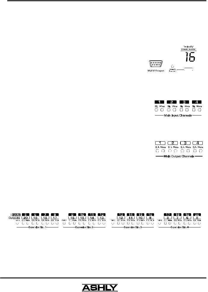
4.1 RS-232 Dataport
The 24.24M has two RS-232 dataports wired in parallel, one on the front panel and one on the back, for connecting to a computer for software control. See section 7.3 for details on connecting to a computer.
4.2 Device ID/Preset Number
This LED and switch have two functions, to select and display the current 24.24M device ID (0-16), or to select and display a user-defined preset number (1-35). The switch and LED display mode is set within Protea System Software under the Options menu, and the switch can be disabled from there as well. When set to preset number mode, the green LED near
the switch is lit. To select a new preset, press and hold the switch until the desired preset number is displayed. When the preset button is released, the
new preset is loaded.
4.3 Main Input Channel LEDs
The 24.24M base unit has four fixed input channels, each of which can be routed to any combination of output channels. Each input channel's two color Sig
LED indicates input signal level of -20dB (green), or +20dB clip (red) respectively. The Sig LEDs detect signal levels after any gain adjustments are made within the
24.24M preamp section. The red input mute LED becomes lit when an input channel is muted through software.
4.4 Main Output Channel LEDs
The four fixed output channels on the 24.24M have three color LEDs to indicate signal, limiter threshold, and clip. The green signal LED indicates -20dB output level. The amber limiter threshold LED depends on settings established within Protea System Software, and, assuming the limiter is active, indicates that sufficient signal level has been reached for the limiter to begin the process of gain reduction. Clipping occurs at +20dB and is indicated by a red LED. The red output mute LED becomes lit when an output channel is muted through software control.
4.5 Expansion Module LEDs
The 24.24M base model is expandable by up to 16 additional inputs or outputs. Expansion modules of four inputs or four outputs each can be field installed by a qualified service technician. If an expansion card slot has been filled, its respective LED (EXP 1, EXP 2, etc.) is automatically lit. The LED indicators on unused expansion slots remain inactive.
5
Operating Manual - 24.24M Matrix Processor
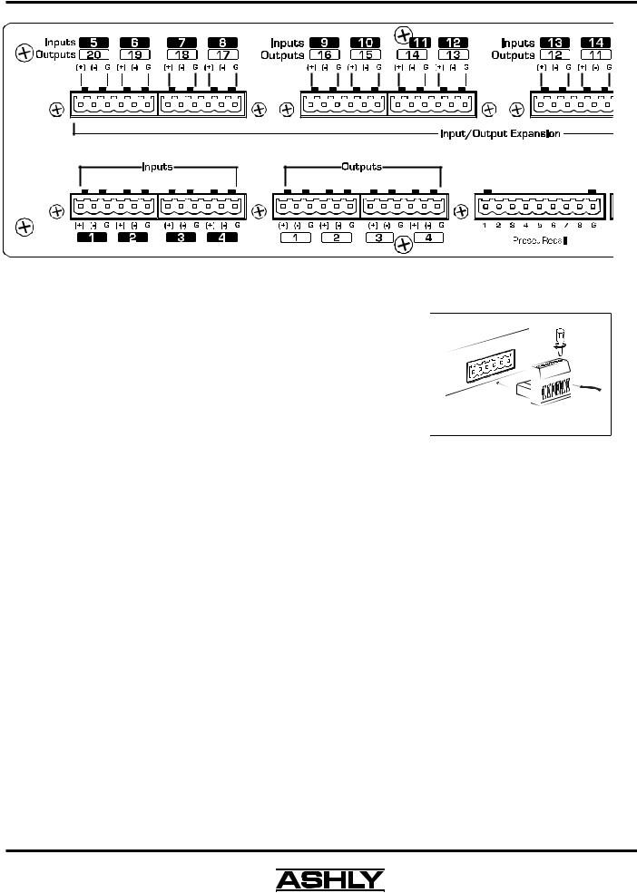
5. REAR PANEL FEATURES
5.1 Input Connections
Balanced input signals are connected to the 24.24M using the included "Euro Block" connector. A flat blade screwdriver is required to connect a stripped wire lead to the loose connector, which is then inserted into the rear panel Euro Block receptacle. It is important that both (+) and (-) inputs are properly terminated or signal loss and noise may result. In other words, if an unbalanced input signal is used, connect the signal to the (+) input, and connect the ground wire to both the (-) and ground connection.
Euroblock
Connector
System
5.2 Output Connections
Like the inputs, output connections are made using the included "Euro Block" connector. All outputs are servo balanced, and may be wired balanced or unbalanced. For unbalanced output connections, use (+) and ground and tie (- ) to ground.
5.3 Expansion Modules
The 24.24M base model is expandable by up to 16 additional inputs or outputs. Expansion modules of four inputs or four outputs each can be installed. Input expansion modules use green Euroblock connectors, while output expansion modules use black connectors. Removable metal plates cover unused expansion slots on the back panel.
5.4 Preset Recall
There are no user controls on the 24.24M, making it ideal for permanent installations where security is an issue. There may be times, however, where real time variables require changes in system settings, such as EQ, gain, and delay settings changing when a room size changes. For these types of changes, the 24.24M offers the ability to recall up to eight different presets using contact closures. Contact closures are nothing more than external, user installed switches that, when closed, recall a previously defined preset which at once applies changes to the settings of all inputs and outputs. The switches can be anything from a rotary switch on a control room panel, to automatic door sensors scattered throughout a conference center, to a microphone key switch, etc. Contact closures allow for flexibility while maintaining a high degree of system security.
To use contact closure switching, up to eight presets (1-8) must first be defined according to the needs of the installation. Switches are to be configured so that closing the switch contact triggers the preset recall event. It doesn't matter if the switch is momentary or latching, the only thing that triggers the event is the transition from open to closed for a given circuit. Closing a circuit will automatically override any previously recalled presets. Up to eight switches
6
Operating Manual - 24.24M Matrix Processor
can be used, with all switches sharing a common ground connection. The number below the nine pin Euro Block contact closure connector equals the number of the preset which will be recalled when that switch is closed. Always use the 24.24M contact closure ground for contact closure switches. Do not connect the 24.24M contact closure ground to any other external grounds, as ground loop currents may result.
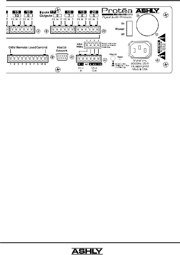
5.5 0-5V Remote Level Control
Any of the inputs or outputs on the 24.24M can have their levels remotely controlled through this simple DC control port. Use the provided +5VDC and Ground (pins 9 and 10), along with a potentiometer, switched resistor network, or relay (for muting), to return a DC voltage to the desired input or output control pin. Using Protea System Software, each pin can be assigned any combination of inputs or outputs to create up to eight remote control groups (see sec 11.1).
The remote level control can only attenuate the signal, it can not provide gain, so properly set up the gain structure within the 24.24M before using remote level control. +5V on any control pin has no attenuating effect, while 0V referenced to the connector ground fully attenuates the signal. Do not connect the remote level control ground to any other external grounds.
5.6 RS-232 Dataport
The 24.24M has two RS-232 dataports, wired in parallel, with one on the front panel and one on the back, for connecting to a computer for software control. See section 7.3 for details on connecting to a computer.
5.7 Data In/Data Out Connection
The Data In and Out connectors are used for connecting the 24.24M to other Protea products under software control, as well as SIA, Crestron, or other third party controllers. Control data for the 24.24M uses the RS-232 protocol, and does not support the MIDI baud rate. Supported baud rates are 9600bps and 38,400bps.
5.8 RS-232 Mode Switch
The RS-232 mode switch is pushed in only when the 24.24M RS-232 Dataport is connected to a PC, and is the first of several Protea products in a data chain (including an active remote).
5.9 AC Inlet and Power Switch
A detachable AC power cord is used on the 24.24M. Since the internal universal power supply works from 90 to
240 VAC 50-60Hz, the only change necessary for use with a different AC mains connection is the appropriate AC power cord. The AC power switch is found on the back of the unit as well.
7
Operating Manual - 24.24M Matrix Processor
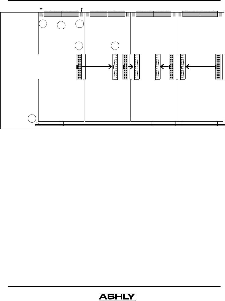
Expansion Card Assembly:
*See ESD Precautions First
1.) Plug ribbon cable into motherboard header
2.) Plug other end of ribbon cable into expansion slot 3.) Slide pcb fingers into slots on back of meter card
4.) Fit Euroblock connectors through back panel cut-outs 5.) Fasten two back panel screws
3
5 4 5
2 1
Flatcable(s)
to
Motherboard
EXP4 |
EXP3 |
EXP2 |
EXP1 |
Expansion Card #4 |
Expansion Card #3 |
Expansion Card #2 |
Expansion Card #1 |
|||||||||||||||||||
|
Inputs 17-20 |
|
Input 13-16 |
|
Inputs 9-12 |
|
Inputs 5-8 |
|||||||||||||||
|
Outputs 5-8 |
|
Outputs 9-12 |
|
Outputs 13-16 |
|
Outputs 17-20 |
|||||||||||||||
|
|
|
|
|
|
|
|
|
|
|
|
|
|
|
|
|
|
|
|
|
|
|
|
|
|
|
|
|
|
|
|
|
|
|
|
|
|
|
|
|
|
|
|
|
|
6. EXPANSION MODULE INSTALLATION
The Ashly 24.24M can be ordered from the factory with expansion modules pre-installed to suit the application, or as a 4 x 4 base unit. Should the need arise to add input or output capacity at a later time, additional four channel input or output modules can be purchased and easily installed in the field.
There are a total of four expansion slots available, and each slot accepts either an input or an output module. The 24.24M as well as Protea System Software autodetect if a slot has been filled, and whether it is an input or output. The software interface automatically updates to reflect the current 24.24M expansion slot configuration.
Please note that while field installation is not complicated, there is a risk of ESD (electrostatic discharge) damage to circuit board components if the board is improperly handled.
To install an additional expansion module, refer the following procedure to a qualified service technician: 1.) Remove AC power cord from back of unit and place unit on grounded work surface.
2.) Remove the seven top cover screws and remove cover. Remove expansion slot covers from back panel.
3.) Discharge any personal static by touching a grounded object. Carefully remove the new expansion card and flat cable from the ESD protective bag.
4.) Follow the instructions in the above drawing for installing expansion modules. Ashly recommends placing input expansion modules starting with EXP1, and placing output expansion modules starting from EXP 4 and working backwards. This way input and output channels are continuously numbered up from channel 1.
6.) In some cases it may be necessary to remove an existing expansion card before installing an new adjacent one. Certain motherboard flatcable headers may be inaccessible with modules installed above them.
7.) Make sure all hardware is secure, then replace top cover.
For further information on expansion module assembly or proper ESD protection, please contact the Ashly service department at 1-800-828-6308.
8

Operating Manual - 24.24M Matrix Processor
7. PROTEA SYSTEM SOFTWARE
Ashly offers a powerful software interface for the Windows PC environment, providing control for the 24.24M Matrix Processor, 4.24D distribution system processor, 4.24C crossover, 4.24G graphic EQ and slaves, two parametric EQ slaves (2.24P and 4.24P), and the VCM-88(E and C), high performance eight channel remote level controllers. Within Protea System Software, each device has its own separate visual interface. All controls are intuitively represented in a user friendly way, and on-line help is available for key functions.
7.1 How to get Protea System Software
Protea System Software is shipped free with each new Protea 24.24M, can be downloaded from the Ashly web site, or can be purchased directly from Ashly for a nominal handling fee.
7.2 Installing Protea System Software
The installation program is the same whether from the web site or from a disk, and is called <Pssinstl_xx.exe>. To install Protea System Software, double-click on <Pssinstl_xx.exe> and follow the installation instructions.
7.3 Connecting the 24.24M to a computer
A standard D-Sub nine pin female to male connector cable is used to connect a PC to the 24.24M. If the PC lacks a nine pin RS-232 port, an active USB to RS-232 converter can be purchased at computer stores. Here are the suggested steps for connecting the 24.24M to a PC:
1)Plug the RS-232 cable into an available serial port on the PC.
2)Plug the other end of the cable into either the front or back RS-232 Dataport on the 24.24M.
3)Turn on the power to the 24.24M.
4)Open Protea System Software (version 6 .4 or higher).
5)Go to the <Devices> menu and select <24.24M>.
6)Select the appropriate COMM port (Comm 1-16).
9
 Loading...