


ne24.24M
24 Bit Digital
Multiple Channel
Matrix Processor
Operating Manual
ASHLY AUDIO INC.
847 Holt Road Webster, NY 14580-9103 Phone: (585) 872-0010
Toll-Free: (800) 828-6308 Fax: (585) 872-0739
www.ashly.com

Operating Manual - ne24.24M Matrix Processor
Important Safety Instructions
Consignes de sécurité à lire attentivement
The lightning flash with arrowhead symbol, within an equilateral triangle, is intended to alert the user to the presence of uninsulated “dangerous voltage” within the product’s enclosure that may be of sufficient magnitude to constitute a risk of electric shock to persons. The exclamation point within an equilateral triangle is intended to alert the user to the presence of important operating and maintenance instructions in the literature accompanying the device
Le symbole de la flèche dans un triangle équilateral symbolisant la foudre est prévu pour sensibiliser l’utilisateur à la présence de tension de voltage non isolée à l’intérieur de l’appareil. Elle pourrait constituer un danger de risque de décharge électrique pour les utilisateurs. Le point d’exclamation dans le triangle équilatérale alerte l’utilisateur de la présence de consignes qu’il doit d’abord consulter avant d’utiliser l’appareil.
1.Read these instructions.
2.Keep these instructions.
3.Heed all warnings.
4.Follow all instructions.
5.To reduce the risk of fire or electric shock, do not expose this apparatus to rain or moisture.
6.Do not use this apparatus near water.
7.Clean only with dry cloth.
8.Do not block any ventilation openings. Install in accordance with the manufacturer’s instructions.
9.Do not install near any heat sources such as radiators, heat registers, stoves, or other apparatus (including amplifiers) that produce heat.
10.Do not defeat the safety purpose of the polarized or grounding-type plug. A polarized plug has two blades with one wider than the other. A grounding type plug has two blades and a third grounding prong. The wide blade or the third prong are provided for your safety. If the provided plug does not fit into your outlet, consult an electrician for replacement of the obsolete outlet.
11.Protect the power cord from being walked on or pinched particularly at plugs, convenience receptacles, and the point where they exit from the apparatus.
12.Only use attachments/accessories specified by the manufacturer.
13.Use only with the cart, stand, tripod, bracket, or table specified by the manufacturer, or sold with the apparatus. When a cart is used, use caution when moving the cart/apparatus combination to avoid injury from tip-over.
14.Unplug this apparatus during lightning storms or when unused for long periods of time.
15.Refer all servicing to qualified service personnel.
Servicing is required when the apparatus has been damaged in any way, such as power-supply cord or plug is damaged, liquid has been spilled or objects have fallen into the apparatus, the apparatus has been exposed to rain or moisture, does not operate normally, or has been dropped.
1.Lisez ces instructions.
2.Conservez ces instructions.
3.Observez les avertissements.
4.Suivez ces instructions.
5.Pour réduire le risque de feu ou la décharge électrique, ne pas exposer cet appareil pour pleuvoir ou l’humidité.
6.Ne pas utiliser l’appareil près de l’eau.
7.Le nettoyer à l’aide d’un tissus sec.
8.Ne pas bloquer les ouvertures de ventilation, installer selon les consignes du fabricant.
9.Eloigner des sources de chaleur tel: radiateurs, fourneaux ou autres appareils qui produisent de la chaleur.
10.Ne pas modifier ou amputer le système de la mise à terre. Une prise avec mise à terre comprend deux lames dont une plus large ainsi qu’une mise à terre: ne pas la couper ou la modifier. Si la prise murale n’accepte pas la fiche, consulter un électricien pour qu’il remplace la prise désuète.
11.Protéger le cordon de secteur contre tous bris ou pincement qui pourraient l’endommager, soit à la fiche murale ou à l’appareil.
12.N’employer que les accessoires recommandés par le fabricant.
13.N’utiliser qu’avec les systèmes de fixation,chariots, trépied ou autres, approuvés par le fabricant ou vendus avec l’appareil.
14.Débrancher l’appareil lors des orages électriques ou si inutilisé pendant une longue période de temps.
15.Un entretient effectué par un centre de service accrédité est exigé si l’appareil a été endommagé de quelque
façon: si il a été exposé à la pluie,, l’humidité ou s’il ne fonctionne pas normalement ou qu’il a été échappé.
FCC Compliance
This device complies with part 15 of the FCC Rules. Operation is subject to the following two conditions:
1.This device may not cause harmful interference
2.This device must accept any interference received, including interference that may cause undesired operation
Note:ThisequipmenthasbeentestedandfoundtocomplywiththelimitsforaClassBdigitaldevice,pursuanttopart15oftheFCCRules.Theselimitsaredesigned to provide reasonable protection against harmful interference in both a commercial and residential installation. This equipment generates, uses and can radiate radio frequency energy and, if not installed and used in accordance with the instructions, may cause harmful interference to radio communications. However, there is no guarantee that interference will not occur in a particular installation. If this equipment does cause harmful interference to radio or television reception, which can be determined by turning the equipment off and on, the user is encouraged to try to correct the interference by one or more of the following measures:
-Reorient or relocate the receiving antenna.
-Increase the separation between the equipment and receiver.
-Connect the equipment into an outlet on a circuit different from that to which the receiver is connected.
-Consult the dealer or an experienced radio/TV technician for help.
2

|
|
|
Operating Manual - ne24.24M Matrix Processor |
|
|
|
|
1 |
INTRODUCTION |
Table Of Contents |
|
. . . . . . . . . . . . . . . . . . . . . . . . . . . . . . . . . . . . . . . . . . . . . . . . . . . . 4 |
|||
2 |
UNPACKING .. . . . . . . . . . . . . . . . . . . |
. . . . . . . . . . . . . . . . . . . . . . . . . . . . . . . . . . . . . . . . . . . . . . . . . . . .4 |
|
3 AC POWER REQUIREMENTS . . . |
. . . . . . . . . . . . . . . . . . . . . . . . . . . . . . . . . . . . . . . . . . . . . . . . . . . .4 |
||
4 |
FRONT PANEL FEATURES .. . . . . |
. . . . . . . . . . . . . . . . . . . . . . . . . . . . . . . . . . . . . . . . . . . . . . . . . . . .5 |
|
|
4..1 RS-232 Dataport. . . . . . . . . . . . . . |
. . . . . . . . . . . . . . . . . . . . . . . . . . . . . . . . . . . . . . . . . . . . . . . . . . . .5 |
|
|
4..2 Com LED . . . . . . . . . . . . . . . . . . . |
. . . . . . . . . . . . . . . . . . . . . . . . . . . . . . . . . . . . . . . . . . . . . . . . . . . .5 |
|
|
4..3 |
Preset Number.. . . . . . . . . . . . . . . |
. . . . . . . . . . . . . . . . . . . . . . . . . . . . . . . . . . . . . . . . . . . . . . . . . . . .5 |
|
4..4 |
Main Input Channel LEDs . . . . . . |
. . . . . . . . . . . . . . . . . . . . . . . . . . . . . . . . . . . . . . . . . . . . . . . . . . . .5 |
|
4..5 |
Main Output Channel LEDs. . . . . |
. . . . . . . . . . . . . . . . . . . . . . . . . . . . . . . . . . . . . . . . . . . . . . . . . . . .5 |
|
4..6 |
Expansion Module LEDs . . . . . . . |
. . . . . . . . . . . . . . . . . . . . . . . . . . . . . . . . . . . . . . . . . . . . . . . . . . . .5 |
5 REAR PANEL FEATURES .. . . . . . . . . . . . . . . . . . . . . . . . . . . . . . . . . . . . . . . . . . . . . . . . . . . . . . . . . . .6 5..1 Input Connections.. . . . . . . . . . . . . . . . . . . . . . . . . . . . . . . . . . . . . . . . . . . . . . . . . . . . . . . . . . . . . . . .6 5..2 Output Connections.. . . . . . . . . . . . . . . . . . . . . . . . . . . . . . . . . . . . . . . . . . . . . . . . . . . . . . . . . . . . . . .6 5..3 Expansion Modules.. . . . . . . . . . . . . . . . . . . . . . . . . . . . . . . . . . . . . . . . . . . . . . . . . . . . . . . . . . . . . . .6 5..4 Logic Inputs/Preset Recall.. .. .. .. .. .. .. .. .. .. .. .. .. .. .. .. .. .. .. .. .. .. .. .. .. .. .. .. .. .. .. .. .. .. .. .. .. .. .. .. .. .. .. .. .. .. .. .. .. .. .. .. .. .. .. .. .. ..6 5..5 Ethernet Control Jack . . . . . . . . . . . . . . . . . . . . . . . . . . . . . . . . . . . . . . . . . . . . . . . . . . . . . . . . . . . . . .7 5..6 0-5V Remote Level Control . . . . . . . . . . . . . . . . . . . . . . . . . . . . . . . . . . . . . . . . . . . . . . . . . . . . . . . . .7 5..7 RS-232 Dataport. . . . . . . . . . . . . . . . . . . . . . . . . . . . . . . . . . . . . . . . . . . . . . . . . . . . . . . . . . . . . . . . . .7 5..8 Data In/Data Out Connection. . . . . . . . . . . . . . . . . . . . . . . . . . . . . . . . . . . . . . . . . . . . . . . . . . . . . . . .7 5..9 Factory Reset Switch.. . . . . . . . . . . . . . . . . . . . . . . . . . . . . . . . . . . . . . . . . . . . . . . . . . . . . . . . . . . . . .8 5..10 AC Inlet and Power Switch.. . . . . . . . . . . . . . . . . . . . . . . . . . . . . . . . . . . . . . . . . . . . . . . . . . . . . . . .8
6 EXPANSION MODULE INSTALLATION . . . . . . . . . . . . . . . . . . . . . . . . . . . . . . . . . . . . . . . . . . . . . . .8 7 PROTEAne SOFTWARE . . . . . . . . . . . . . . . . . . . . . . . . . . . . . . . . . . . . . . . . . . . . . . . . . . . . . . . . . . . . . .9
8 AUDIO FUNCTIONS .. . . . . . . . . . . . . . . . . . . . . . . . . . . . . . . . . . . . . . . . . . . . . . . . . . . . . . . . . . . . . . .10 8..1 Input Audio Functions.. . . . . . . . . . . . . . . . . . . . . . . . . . . . . . . . . . . . . . . . . . . . . . . . . . . . . . . . . . . .10 8..2 Output Audio Functions . . . . . . . . . . . . . . . . . . . . . . . . . . . . . . . . . . . . . . . . . . . . . . . . . . . . . . . . . . .14
9 OTHER SOFTWARE FUNCTIONS . . . . . . . . . . . . . . . . . . . . . . . . . . . . . . . . . . . . . . . . . . . . . . . . . . .17 9..1 Device Options. . . . . . . . . . . . . . . . . . . . . . . . . . . . . . . . . . . . . . . . . . . . . . . . . . . . . . . . . . . . . . . . . .17 9..2 Preset Options.. . . . . . . . . . . . . . . . . . . . . . . . . . . . . . . . . . . . . . . . . . . . . . . . . . . . . . . . . . . . . . . . . .17 9..3 Copying Settings To Another Input Or Output. . . . . . . . . . . . . . . . . . . . . . . . . . . . . . . . . . . . . . . . . .17 9..4 Security. . . . . . . . . . . . . . . . . . . . . . . . . . . . . . . . . . . . . . . . . . . . . . . . . . . . . . . . . . . . . . . . . . . . . . . .17 9..5 Metering . . . . . . . . . . . . . . . . . . . . . . . . . . . . . . . . . . . . . . . . . . . . . . . . . . . . . . . . . . . . . . . . . . . . . . .18
10 REMOTE CONTROL . . . . . . . . . . . . . . . . . . . . . . . . . . . . . . . . . . . . . . . . . . . . . . . . . . . . . . . . . . . . . .18 10..1 WR-1 Volume Control.. . . . . . . . . . . . . . . . . . . . . . . . . . . . . . . . . . . . . . . . . . . . . . . . . . . . . . . . . . .18 10..2 WR-1..5 Volume Control and Preset Recall.. . . . . . . . . . . . . . . . . . . . . . . . . . . . . . . . . . . . . . . . . . .19 10..3 WR-2 Contact Closure Preset Recall . . . . . . . . . . . . . . . . . . . . . . . . . . . . . . . . . . . . . . . . . . . . . . . .19 10..4 WR-5 Programmable Zone Controller . . . . . . . . . . . . . . . . . . . . . . . . . . . . . . . . . . . . . . . . . . . . . . .20 10..5 neWR-5 Networked Programmable Zone Controller.. . . . . . . . . . . . . . . . . . . . . . . . . . . . . . . . . . .21 10..6 RD-8C Remote Level Attenuator. . . . . . . . . . . . . . . . . . . . . . . . . . . . . . . . . . . . . . . . . . . . . . . . . . .21 10..7 FR-8 and FR-16 Networked Programmable Fader Controllers . . . . . . . . . . . . . . . . . . . . . . . . . . . .22 10..8 Ashly Remote Application for iPad®. . . . . . . . . . . . . . . . . . . . . . . . . . . . . . . . . . . . . . . . . . . . . . . .22
11 GPO LOGIC OUTPUT . . . . . . . . . . . . . . . . . . . . . . . . . . . . . . . . . . . . . . . . . . . . . . . . . . . . . . . . . . . . .22 12 TROUBLESHOOTING TIPS . . . . . . . . . . . . . . . . . . . . . . . . . . . . . . . . . . . . . . . . . . . . . . . . . . . . . . . .23 13 SPECIFICATIONS .. . . . . . . . . . . . . . . . . . . . . . . . . . . . . . . . . . . . . . . . . . . . . . . . . . . . . . . . . . . . . . . .24 14 TYPICAL APPLICATIONS . . . . . . . . . . . . . . . . . . . . . . . . . . . . . . . . . . . . . . . . . . . . . . . . . . . . . . . . .25
15 LIMITED WARRANTY . . . . . . . . . . . . . . . . . . . . . . . . . . . . . . . . . . . . . . . . . . . . . . . . . . . . . . . . . . . .27
3

Operating Manual - ne24.24M Matrix Processor
1.. INTRODUCTION
Thank you for your purchase of the Protea ne24..24M.. The Protea ne24..24M Matrix Processor uses modular expansion cards to provide up to twenty-four channels of audio matrixing and processing, along with provisions for remote control and logic output. The base unit offers a four-input/four-output configuration. Each input and output expansion card has individual
DSP processing allowing expansion of the base unit’s total inputs or outputs four channels at a time.. In addition, an eight channel general purpose logic control output expansion card is available for controlling lighting or AV equipment through the Protea NE Software, or by recalling presets..
Expansion cards - Inputs, outputs, or a logic output card are easily installed in the field without the need to reset switches or reprogram the device..
Input channel processing blocks include: Mic Preamp with up to 60dB Gain, 48V Phantom Power and “Push to Talk” switching, Input Level with Polarity, Passive potentiometer or active RD-8C Remote Level Control, Time Delay, Fifteen Band Fully Parametric EQ, Noise Gate, Autoleveler, and Ducker..
Output channel processing blocks consist of a Cross Point Mixer, HPF/LPF, Delay, fifteen EQ Filters, Gain, Remote
Level Control, and Limiter.. The cross point mixer in the output section allows you to route any input to any output at any level and mute any input at any output without affecting the input configuration. The HPF/LPF crossover section offers Bessel, Butterworth and Linkwitz-Riley filters with 12, 18, 24 and 48dB octave slopes.
Matrixing allows you to route any input to any output and control individual levels once they have been assigned.. Fixed path architecture and extensive processing power per channel will reduce the amount of time it takes to set up the system..
Programming requires Ashly’s Protea NE Software on a Windows PC using a standard 10/100BASE-T ethernet connection.. Note: Protea NE Software will not work over RS-232, that is used for non-ethernet systems only..
Connectors are euroblock for all audio inputs and outputs, eight Logic Inputs for preset recall, eight channels of remote DC level control, and a data connection for Ashly’s WR-5 active remote.. Ethernet uses an RJ45 connector, while RS-232 uses a Dsub 9 female..
2.. UNPACKING
As a part of our system of quality control, every Ashly product is carefully inspected before leaving the factory to ensure flawless appearance.After unpacking, please inspect for any physical damage. Save the shipping carton and all packing materials , as they were carefully designed to reduce to minimum the possibility of transportation damage should the unit again require packing and shipping.. In the event that damage has occurred, immediately notify your dealer so that a written claim to cover the damages can be initiated. The right to any claim against a public carrier can be forfeited if the carrier is not notified promptly and if the shipping carton and packing materials are not available for inspection by the carrier.. Save all packing materials until the claim has been settled..
3.. AC POWER REQUIREMENTS
Note: The AC power switch for model ne24..24M is on the back panel.. The Protea ne24..24M uses a universal input power supply which will accept any line voltage from 90VAC to 240VAC, 50-60Hz.. A standard IEC-320 grounded AC inlet is provided on the rear panel to accept the detachable power cord.. Never remove the AC earth ground connection to the ne24..24M.. In the event of fuse failure, refer the product to a qualified service technician for fuse replacement, replacing only with the same type and rating fuse..
WARNING: THIS APPARATUS MUST BE EARTH GROUNDED THROUGH THE SUPPLIED POWER LINE CORD
4
Operating Manual - ne24.24M Matrix Processor
4.. FRONT PANEL FEATURES
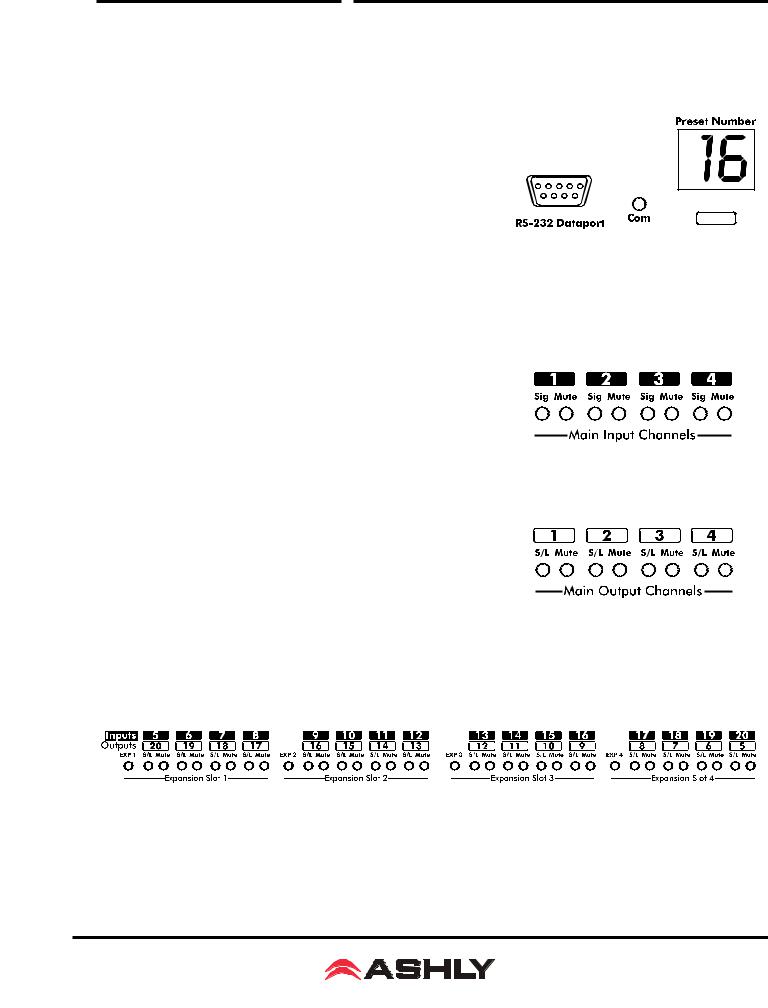
4..1 RS-232 Dataport
The ne24..24M has two RS-232 dataports wired in parallel, one on the front panel and one on the back, for connecting to non-ethernet control hardware.. Protea NE Software does not work over RS-232..
4..2 Com LED
This green LED lights for a few seconds whenever there is communication activity to the unit from a host PC.. It is also used to respond to an "identify device" command from NE software..
4..3 Preset Number
This displays the current preset number (1-31).. The switch can be disabled from software.. To select a new preset, press and hold the switch until the desired preset number is displayed.. When the preset button is released, the new preset is loaded.. This display is also used to indicate firmware revision during start-up, and status during factory reset.
4..4 Main Input Channel LEDs
The ne24.24M base unit has four fixed input channels. Each input channel’s two color Sig LED indicates input signal level of -20dB (green), or +20dB clip (red) respectively.. The Sig LEDs detect signal levels after any gain adjustments are made within the ne24..24M preamp section.. The red input mute LED becomes lit when an input channel is muted through software or remote control..
4..5 Main Output Channel LEDs
The four fixed output channels on the ne24.24M have three color
LEDs to indicate signal, limiter threshold, and clip.. The green signal LED indicates -20dB output level.. The amber limiter threshold LED depends on settings established within Protea System Software, and, assuming the limiter isactive,indicatesthatsufficientsignallevelhasbeenreachedforthelimiterto begin the process of gain reduction.. Clipping occurs at +20dB and is indicated by a red LED.. The red output mute LED becomes lit when an output channel is muted through software or remote control..
4..6 Expansion Module LEDs
The ne24..24M is expandable by adding up to 16 additional inputs or outputs.. Expansion modules of four inputs or four outputs each can be field installed by a qualified service technician. If an expansion card slot has been filled, its respective amber LED (EXP 1, EXP 2, etc..) is automatically lit.. The LED indicators on unused expansion slots do not light..
5

Operating Manual - ne24.24M Matrix Processor
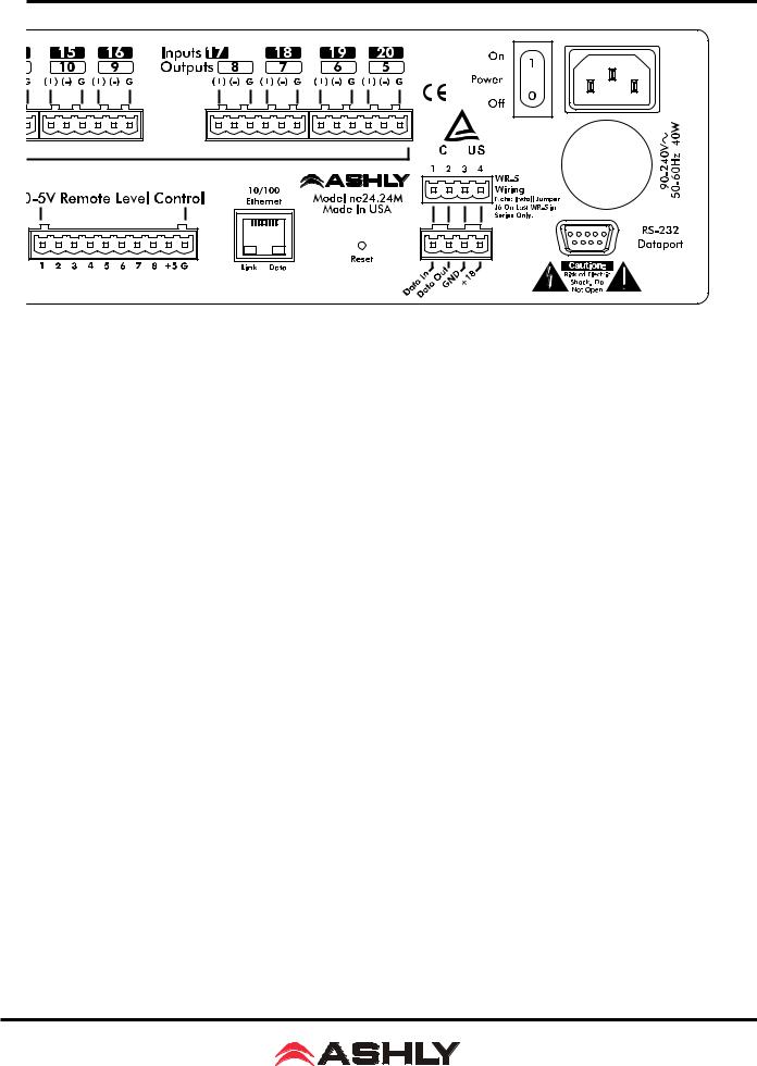
5.. REAR PANEL FEATURES
5..1 Input Connections
Balanced input signals are connected to the ne24..24M using the included euroblock connector. A flat blade screwdriver is required to connect a stripped wire lead to the external connector piece, which is then inserted into the rear panel Euro Block receptacle.. It is important that both (+) and (-) inputs are properly terminated or signal loss and noise may result.. In other words, if an unbalanced input signal is used, connect the signal to the (+) input, and connect the ground wire to both the (-) and ground connection..
5..2 Output Connections
Like the inputs, output connections are made using the included euroblock connector.. All outputs are servo balanced, and may be wired balanced or unbalanced.. For unbalanced output connections, use (+) and ground and tie (-) to ground..
5..3 Expansion Modules
The ne24..24M base model is expandable by up to 16 additional inputs or outputs, as well as a single module card used for eight general purpose logic outputs (GPO).. Expansion modules of four inputs or four outputs each can be installed in any expansion slot.. Input expansion modules use green euroblock connectors, while output expansion modules use black connectors.. Removable metal plates cover unused expansion slots on the back panel.. The optional Logic Output card (GPO) is used to drive preset controlled relays or another device’s logic control inputs.. The GPO comes with a function and wiring sticker which must be placed on the ne24..24M back panel above the Input/Output slot where the GPO option is installed.. Only one GPO can be installed in a ne24..24M..
5..4 Logic Inputs (Preset Recall)
There are no user controls on the ne24..24M, making it ideal for permanent installations where security is an issue.. There may be times, however, where real time variables require changes in system settings, such as EQ, gain, and delay settings changing when a room size changes.. For these types of changes, the ne24..24M offers the ability to recall up to eight different presets, or switch other events such as a mic input “push to talk” using contact closures.. Contact closures are nothing more than external, user installed switches that, when closed, recall a previously defined preset which applies changes to the settings of all inputs and outputs.. The switches can be anything from a rotary switch on a control room panel, to automatic door sensors scattered throughout a conference center, to a microphone key switch, etc. Contact closures allow for flexibility while maintaining a high degree of system security..
6
Operating Manual - ne24.24M Matrix Processor
To use contact closure switching, up to eight presets (1-8) must first be defined according to the needs of the installation.
To use the mic input “Push To Talk” feature, select the “Push To Talk Mic” checkbox in the Protea NE Software’s mic preamp dialog box and assign it a logic input pin.. The preset recall feature for that contact closure is then deactivated.. Switches are to be configured so that closing the switch contact triggers the preset recall event. It doesn’t matter if the switch is momentary or latching, the only thing that triggers the event is the transition from open to closed for a given circuit.. Closing a circuit will automatically override any previously recalled presets.. Up to eight switches can be used, with all switches sharing a common ground connection.. The number below the nine pin Euro Block contact closure connector equals the number of the preset which will be recalled when that switch is closed.. Always use the ne24..24M contact closure ground for contact closure switches.. Do not connect the ne24..24M contact closure ground to any other external grounds..
5..5 10/100 Ethernet Control Jack
Use this RJ-45 jack to connect directly to a computer or to a 10/100 Base-T ethernet network using Protea NE Software for access to the comprehensive suite of device setup, audio controls, and monitoring functions..
5..6 0-5V Remote Level Control
Any of the inputs or outputs on the ne24..24M can have their levels remotely controlled through this simple DC control port.. Use the provided +5VDC and Ground (pins 9 and 10), along with a potentiometer, switched resistor network, or relay (for muting), to return a DC voltage to the desired input or output control pin.. Using Protea NE Software, each remote level control pin can be assigned any combination of inputs or outputs to create up to eight remote control groups (see sec 11..1).. The remote level control can only attenuate the signal, it can not provide gain, so properly set up the gain structure within the ne24..24M before using remote level control.. +5V on any control pin has no attenuating effect, while 0V referenced to the connector ground fully attenuates the signal.. Do not connect the remote level control ground to any other external grounds..
5..7 RS-232 Dataport
The ne24..24M has two RS-232 dataports, wired in parallel, with one on the front panel and one on the back, for connecting to a computer for AMX, Crestron, or other third party non-ethernet controllers.. Control data for the this jack uses the RS-232 protocol, and does not support the MIDI baud rate.. Supported baud rates are 9600bps and 38,400bps.. Protea NE
Software will not work using RS-232, use ethernet instead..
5..8 Data In/Data Out Connection
The Data In and Out connectors are used for connecting the ne24..24M to the Ashly WR-5 programmable remote controller or the RD-8C level controller..
7
Operating Manual - ne24.24M Matrix Processor
5..9 Factory Reset Switch
Factory reset is used to clear all user defined preset names and control values and reset them to their original factory settings.. Factory reset to the ne24..24M is accomplished by pressing and holding a recessed switch on the back panel during power up.. The switch is found in a small hole labelled “Reset”.. There is a 10 second countdown in the front panel LED display to indicate a factory reset is about to occur.. Releasing the switch or shutting off power at any time during the countdown will stop the factory reset from occurring. At the end of the countdown, the letters “Fr” flash in the display for about 20 seconds until factory reset is complete.. In addition to resetting all presets to factory default, any password or security settings will be lost when a factory reset is performed..
5..10 AC Inlet and Power Switch
A detachable AC power cord is used on the ne24..24M.. Since the internal universal power supply works from 90 to 240 VAC 50-60Hz, the only change necessary for use with a different AC mains connection is the appropriate AC power cord.. The AC power switch is found on the back of the unit..
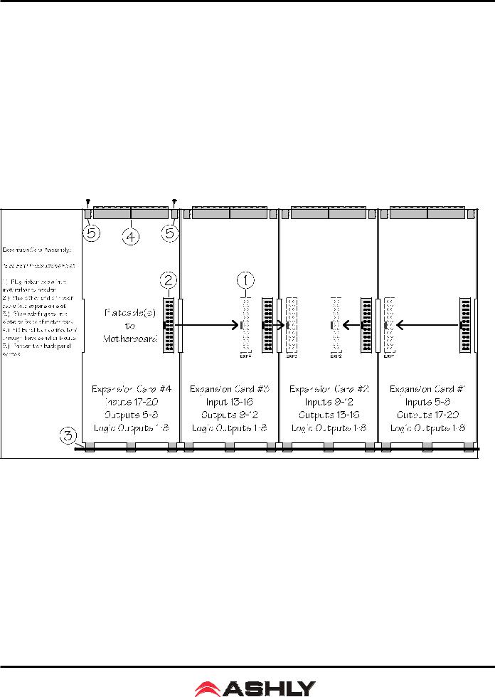
6.. EXPANSION MODULE INSTALLATION
The Ashly ne24..24M can be ordered from the factory with expansion modules pre-installed to suit the application, or as a 4 x 4 base unit.. Should the need arise to add input or output capacity at a later time, as well as logic output function, additional modules can be purchased and easily installed in the field. There are a total of four expansion slots available, and each slot accepts either an input, an output, or a logic output module (GPO).. The ne24..24M as well as Protea NE Software autodetect if a slot has been filled, and whether it is an input, output, or logic output. The software interface automatically updates to reflect the current ne24.24M expansion slot configuration. The logic output expansion module can be installed into any slot, however only one logic output module can be installed. Please note that while field installation is not complicated, there is a risk of ESD
(electrostatic discharge) damage to circuit board components if the board is improperly handled..
To install an additional expansion module, refer the following procedure to a qualified service technician:
1..) Remove AC power cord from back of unit and place unit on grounded work surface..
2..) Remove the seven top cover screws and remove cover.. Remove expansion slot covers from back panel..
3.) Discharge any personal static by touching a grounded object. Carefully remove the new expansion card and flat cable from the ESD protective bag..
8

Operating Manual - ne24.24M Matrix Processor
4..) Follow the instructions in the above drawing for installing expansion modules.. Ashly recommends placing input expansion modules starting with EXP1, and placing output expansion modules starting from EXP 4 and working backwards.. This way input and output channels are continuously numbered up from channel 1..
6..) In some cases it may be necessary to remove an existing expansion card before installing a new adjacent one.. Certain motherboard flatcable headers may be inaccessible with modules installed above them.
7..) Make sure all hardware is secure, then replace top cover..
For further information on expansion module assembly or proper ESD protection, please contact the Ashly service department at 1-800-828-6308..
7.. PROTEAne SOFTWARE
Load the software
Ashly Proteane software is included on a CD with each unit.. Check the Ashly web site at www..ashly..com to verify that you are installing the latest software release.. Autorun will launch the application<ProteaSystemSoftwareNE> to install the
Protea software. Anote about firewalls: When running Protea NE software on a PC for the first time, Windows will prompt the user to allow the software through any active firewalls. Allow this. Once the software is properly installed, Windows must be configured to permanently allow a firewall exemption for Proteane software..
Connect to Ethernet
The Ethernet control connection is made using an RJ-45 terminated eight conductor cable connected directly to a computer or indirectly over a standard 10/100M Ethernet network.. Maximum cable distance for Ethernet is 100 meters from the nearest hub or switch for copper twisted pair CAT5 cable.. For more detailed information about the proper implementation of an ethernet network, review one of the many comprehensive Ethernet networking guides available on the internet..
Identify the processor in software
Once the software is loaded to the computer and an Ethernet connection has been made to the NE processor, all Ashly NE products installed on that network will be automatically detected and shown in the active device listing on the left side of the Protea software startup canvas.. In addition to detecting which models are currently online, any factory installed options are also detected and the software control surface for the new NE product automatically displays available controls for the options present.. Note: In the event of multiple processors of the same model on the network, the user can find a single physical unit by right clicking over the unit’s name in the drop down menu or picture on the canvas, and then click <Identify>, which will flash the Com LED on that unit’s face panel for two seconds.
The software scans for active NE devices on power-up, but the user can manually scan at any time as well with <Scan For Devices> at the bottom of the network NE device listing.. Also, all NE devices continuously broadcast their availability to the software.. All currently connected and active NE products are highlighted in green, while NE products which may be or have been formerly installed but are currently off-line or unavailable show up in red.. Individual NE products can be dragged onto the project canvas to simulate physical rack installation groups, but editing each product can be done from either the product list or the canvas..
Proteane software project canvas
The project canvas is used to visually represent and control a fixed physical sound system installation, and can display any networked Ashly NE processors, amplifiers, and remotes used in that system. The user can also place an assortment of isolated control objects such as level faders, single LEDs, meter bars, etc, and map them to specific product functions within that project. Once a control object is placed, right click on it to bring up its properties. Lines, rectangles, text, even image files can be added to create a custom virtual control screen along with the NE devices and individual control objects.. To see all available canvas tools, right click anywhere over open canvas.. Checking <Design Mode> allows placed objects to be moved around, while unchecking <Design Mode> locks objects in place..
9
 Loading...