


Digital Audio Products
4.24C
24 Bit Digital Crossover and System Processor
Operating Manual
ASHLY AUDIO INC.
847 Holt Road Webster, NY 14580-9103 Phone: (585) 872-0010
Toll-Free: (800) 828-6308 Fax: (585) 872-0739
www.ashly.com

Operating Manual - PROTEA SYSTEM II 4.24C Crossover / System Processor
Table Of Contents
1 |
INTRODUCTION . . . . . . . . . . . . . . . . . . . . . . . . . . . . . . . . . . . . . . . . . . . . . . . . |
. 4 |
|
|
1.1 |
Audio Features . . . . . . . . . . . . . . . . . . . . . . . . . . . . . . . . . . . . . . . . . . . . . . . . . . |
4 |
|
1.2 |
User Interface . . . . . . . . . . . . . . . . . . . . . . . . . . . . . . . . . . . . . . . . . . . . . . . . . . . |
4 |
2 |
UNPACKING . . . . . . . . . . . . . . . . . . . . . . . . . . . . . . . . . . . . . . . . . . . . . . . . . . . . . . |
4 |
|
3 |
AC POWER REQUIREMENTS . . . . . . . . . . . . . . . . . . . . . . . . . . . . . . . . . . . . . |
4 |
|
4 |
FRONT PANEL CONTROL FEATURES . . . . . . . . . . . . . . . . . . . . . . . . . . . . |
5 |
|
|
4.1 Function Keys and Data Wheel . . . . . . . . . . . . . . . . . . . . . . . . . . . . . . . . . . . . . |
5 |
|
|
4.2 |
Presets . . . . . . . . . . . . . . . . . . . . . . . . . . . . . . . . . . . . . . . . . . . . . . . . . . . . . . . . . |
5 |
|
4.3 |
Input Select . . . . . . . . . . . . . . . . . . . . . . . . . . . . . . . . . . . . . . . . . . . . . . . . . . . . . |
5 |
|
4.4 |
Output Select . . . . . . . . . . . . . . . . . . . . . . . . . . . . . . . . . . . . . . . . . . . . . . . . . . . . |
5 |
|
4.5 LED Indicators . . . . . . . . . . . . . . . . . . . . . . . . . . . . . . . . . . . . . . . . . . . . . . . . . . |
5 |
|
|
4.6 |
Audio Functions . . . . . . . . . . . . . . . . . . . . . . . . . . . . . . . . . . . . . . . . . . . . . . . . . |
6 |
|
|
4.6a Gain . . . . . . . . . . . . . . . . . . . . . . . . . . . . . . . . . . . . . . . . . . . . . . . . . . . . . . . |
6 |
|
|
4.6b EQ . . . . . . . . . . . . . . . . . . . . . . . . . . . . . . . . . . . . . . . . . . . . . . . . . . . . . . . . . |
6 |
|
|
4.6c Delay. . . . . . . . . . . . . . . . . . . . . . . . . . . . . . . . . . . . . . . . . . . . . . . . . . . . . . . |
7 |
|
|
4.6d Crossover . . . . . . . . . . . . . . . . . . . . . . . . . . . . . . . . . . . . . . . . . . . . . . . . . . . |
8 |
|
|
4.6e Limit . . . . . . . . . . . . . . . . . . . . . . . . . . . . . . . . . . . . . . . . . . . . . . . . . . . . . . |
10 |
|
4.7 |
Other Functions . . . . . . . . . . . . . . . . . . . . . . . . . . . . . . . . . . . . . . . . . . . . . . . . . |
10 |
|
|
4.7a Recall . . . . . . . . . . . . . . . . . . . . . . . . . . . . . . . . . . . . . . . . . . . . . . . . . . . . . |
10 |
|
|
4.7b Save . . . . . . . . . . . . . . . . . . . . . . . . . . . . . . . . . . . . . . . . . . . . . . . . . . . . . . |
11 |
|
|
4.7c Copy . . . . . . . . . . . . . . . . . . . . . . . . . . . . . . . . . . . . . . . . . . . . . . . . . . . . . . |
11 |
|
|
4.7d Mute . . . . . . . . . . . . . . . . . . . . . . . . . . . . . . . . . . . . . . . . . . . . . . . . . . . . . . |
11 |
|
|
4.7e Utilities . . . . . . . . . . . . . . . . . . . . . . . . . . . . . . . . . . . . . . . . . . . . . . . . . . . . |
11 |
|
|
4.7f Factory Reset . . . . . . . . . . . . . . . . . . . . . . . . . . . . . . . . . . . . . . . . . . . . . . . |
12 |
5 |
INTERCONNECT FEATURES . . . . . . . . . . . . . . . . . . . . . . . . . . . . . . . . . . . . . |
12 |
|
|
5.1 Audio Connections . . . . . . . . . . . . . . . . . . . . . . . . . . . . . . . . . . . . . . . . . . . . . . |
12 |
|
|
5.2 |
MIDI Connection . . . . . . . . . . . . . . . . . . . . . . . . . . . . . . . . . . . . . . . . . . . . . . . |
13 |
|
5.3 |
RS-232 Data Connections . . . . . . . . . . . . . . . . . . . . . . . . . . . . . . . . . . . . . . . . |
13 |
2
Operating Manual - PROTEA SYSTEM II 4.24C Crossover / System Processor
6 |
PROTEA SYSTEM SOFTWARE . . . . . . . . . . . . . . . . . . . . . . . . . . . . . . . . . . . . |
14 |
|
6.1 How to Get Protea System Software . . . . . . . . . . . . . . . . . . . . . . . . . . . . . . . . . |
14 |
|
6.2 Installing Protea System Software . . . . . . . . . . . . . . . . . . . . . . . . . . . . . . . . . . . |
14 |
|
6.3 Connecting the 4.24C to a Computer . . . . . . . . . . . . . . . . . . . . . . . . . . . . . . . . . |
14 |
7 |
TROUBLESHOOTING . . . . . . . . . . . . . . . . . . . . . . . . . . . . . . . . . . . . . . . . . . . . |
15 |
|
7.1 Audio Troubleshooting Tips . . . . . . . . . . . . . . . . . . . . . . . . . . . . . . . . . . . . . . . |
15 |
|
7.2 RS-232/MIDI Troubleshooting Tips . . . . . . . . . . . . . . . . . . . . . . . . . . . . . . . . |
15 |
8 |
SPECIFICATIONS . . . . . . . . . . . . . . . . . . . . . . . . . . . . . . . . . . . . . . . . . . . . . . . . |
16 |
9 |
DIMENSIONS . . . . . . . . . . . . . . . . . . . . . . . . . . . . . . . . . . . . . . . . . . . . . . . . . . . . |
17 |
10 |
LIMITED WARRANTY . . . . . . . . . . . . . . . . . . . . . . . . . . . . . . . . . . . . . . . . . . . . |
17 |
11 |
INSTALLATION RECORD . . . . . . . . . . . . . . . . . . . . . . . . . . . . . . . . . . . . . . . . |
18 |
12 |
BLOCK DIAGRAM . . . . . . . . . . . . . . . . . . . . . . . . . . . . . . . . . . . . . . . . . . . . . . . |
20 |
The lightning flash with arrowhead symbol, within an equilateral triangle, is intended to alert the user to the presence of uninsulated "dangerous voltage" within the product's enclosure that may be of sufficient magnitude to constitute a risk of electric shock to persons.
CAUTION
RISK OF ELECTRIC SHOCK
DO NOT OPEN
TO REDUCE THE RISK OF ELECTRIC SHOCK, DO NOT REMOVE COVER. NO USER SERVICEABLE PARTS INSIDE. REFER SERVICING TO QUALIFIED SERVICE PERSONNEL.
TO REDUCE THE RISK OF FIRE OR ELECTRICAL SHOCK, DO NOT EXPOSE THIS APPlIANCE TO RAIN OR MOISTURE.
TO REDUCE THE RISK OF FIRE, REPLACE ONLY WITH SAME TYPE FUSE. REFER REPLACEMENT TO QUALIFIED SERVICE PERSONNEL.
The exclamation point within an eqilateral triangle is intended to alert the user to the presence of important operating and maintenance instructions in the literature accompanying the device.
WARNING:
THIS APPARATUS MUST BE EARTHED
3

Operating Manual - PROTEA SYSTEM II 4.24C Crossover / System Processor
1. INTRODUCTION
Thank you for your purchase of this Ashly Protea 4.24C Digital Crossover/System Processor. The Protea SYSTEM II series builds on the tradition of quality and value which has earned Ashly its place as a market leader in crossovers, equalization, and signal processing.
Your new 4.24C is a four input/eight output digital signal processor capable of precise control of a broad range of audio functions. The front panel interface allows quick access to all control parameters by offering dedicated function buttons, eliminating the need for hidden sub-menus. For even faster set-ups and stronger visualization of Input/Output routing, EQ, and Filter curves, an RS232 PC port is provided for use with Windows™ Protea System Software. Full control is also available via MIDI input and output jacks.
1.1 AUDIO FEATURES
The Protea 4.24C utilizes state of the art DSP technologies, beginning with 24 bit, 48kHz delta-sigma A/D converters with 128x oversampling. Digital processing includes Gain, Polarity Invert, Parametric EQ, Shelving Filters, Time Delay, Crossover Functions, Compression, Limiting, and Signal Routing, all taking place in twin 120MHz Motorola DSP56362 high performance DSP processors. D/A conversion uses 24 bit delta-sigma converters with 128x oversampling. All inputs and outputs are precision balanced and RF protected using XLR connectors.
1.2 USER INTERFACE
Front Panel Interface: A backlit 2 x 20 character LCD displays channel and function settings. Dedicated buttons provide access to all audio functions and system tools. The display indicates the current preset number, then subsequently shows the selected input or output and its active control parameters. Five segment LED arrays on each input and output provide audio level information and mute status.
Protea System Software: The computer interface uses Ashly PROTEA SYSTEM SOFTWARE for Windows, which allows complete PC control of the 4.24C through an RS-232 serial port. Protea system software is supplied with each unit, or can be downloaded at no cost from the Ashly web site. Advantages of using the software include greater preset capacity, and a very intuitive visual representation of the audio routing and control process.
2. UNPACKING
As a part of our system of quality control, every Ashly product is carefully inspected before leaving the factory to ensure flawless appearance. After unpacking, please inspect for any physical damage. Save the shipping carton and all packing materials, as they were carefully designed to minimize the possibility of transportation damage should the unit again require packing and shipping. In the event that damage has occurred, immediately notify your dealer so that a written claim to cover the damages can be initiated. The right to any claim against a public carrier can be forfeited if the carrier is not notified promptly and if the shipping carton and packing materials are not available for inspection by the carrier. Save all packing materials until the claim has been settled.
3. AC POWER REQUIREMENTS
Note: The AC power switch for model 4.24C is on the back panel. The Protea 4.24C uses a universal input power supply which will accept any line voltage in the range of 80VAC to 260VAC, 50-60Hz, and is exceptionally resistant to voltage dips, or "brown outs". A standard IEC-320 grounded AC inlet is provided on the rear panel to accept the detachable power cord. Never remove the AC earth ground connection to the 4.24C. In the event of fuse failure, refer the product to a qualified service technician for fuse replacement, replacing only with the same type and rating fuse.
4
Operating Manual - PROTEA SYSTEM II 4.24C Crossover / System Processor
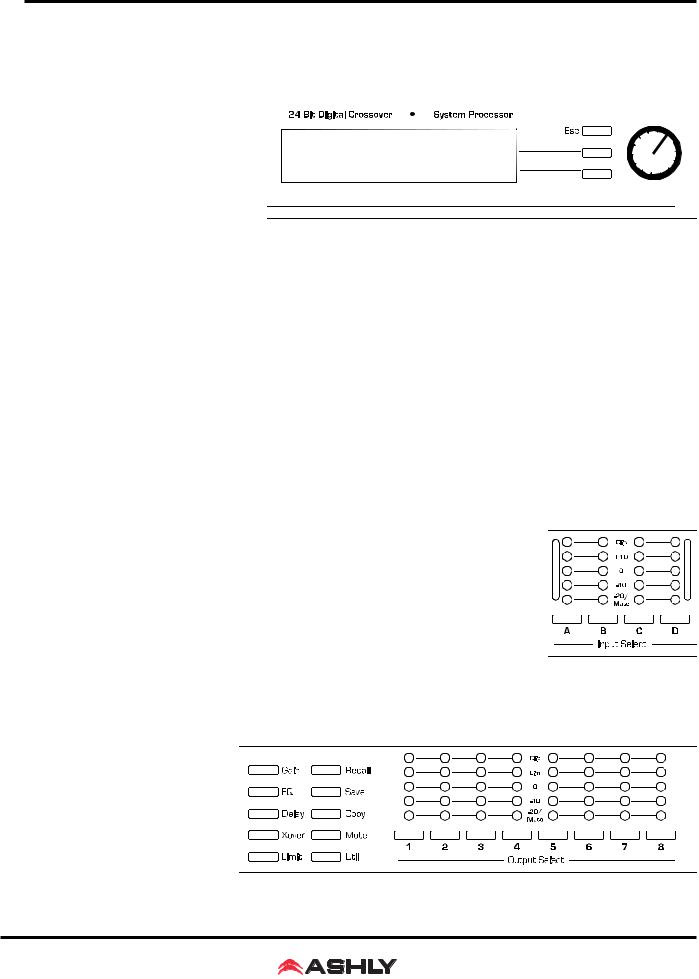
4. FRONT PANEL CONTROL FEATURES
4.1 Function Keys and Data Wheel
To the right of the LCD display
are two unlabeled function keys and a
rotary data wheel. All audio and system parameters are edited using these three controls. Each of the two lines of text on
the LCD display correspond to a dedicated function key, so that various tasks
on both lines may be selected using their respective keys. The selected task is high-
lighted by a flashing underscore beneath the word or number, and the parameter is then adjusted up or down with the data wheel. The Esc key will exit any activity and return to the top level showing the preset number and name.
4.2 Presets
The 4.24C is organized into 30 programmable presets, each completely defining the configuration of all four inputs and eight outputs along with their respective audio components. There are ten repeating preset configurations pre-loaded into the 4.24C which are simply starting points for common applications, and all can be modified, renamed, and saved to suit the end user. Please Note: In addition to the 30 preset numbers, a constantly refreshed Working Preset is used to take a "snapshot" of all current settings should the unit be turned off before changes can be saved.
When the 4.24C is first powered up, the last working preset is loaded, displaying the number and name last used before the unit was turned off. Any modifications made to that preset before saving it will remain in the working preset until either the modified preset is saved, or a fresh preset is recalled to the 4.24C. When modifications to an existing preset are made without saving, the display adds the text (modified) after the preset number.
4.3 Input Select
There are four audio inputs to the 4.24C, and each input is processed independently and may be routed to one or several outputs. Select an input to edit its Gain, EQ, and Delay settings, or to mute it. Signal routing occurs in the output section.
4.4 Output Select
There are eight outputs to the 4.24C, and each output can obtain its source from any input, several combinations of inputs, or no input (off). Select an output channel to edit its Source, Gain, Polarity, EQ, Delay, Crossover, or Limiter functions.
4.5 LED Indicators
Each input and output has a five segment LED array for audio level display, ranging from -20 through clipping. The -20 LED is two-color, also serving as the Mute indicator by turning red. The meter scale is factory set so that 0 on the meter is 0dBu (0.775Vrms), however it can be easily changed to VU scale (0 = +4dBu, or 1.228Vrms) within the Util menu.
5

Operating Manual - PROTEA SYSTEM II 4.24C Crossover / System Processor
4.6 Audio Functions
4.6a Gain
Input and Output Gain are separately adjustable from -40dB to +12dB in 0.1dB increments.
The output gain menu also provides for selection of input source(s) for a given output channel, as well as polarity of the outgoing signal. Input signal sources are A, B, C, D, A+B, C+D, all four inputs combined, or no input (Off). Keep in mind that two signals which share significant content, such as a stereo source, will be up to 6dB louder when combined.
4.6b EQ
The Protea 4.24C EQ section offers full parametric EQ as well as 1st and 2nd order shelving filters on inputs and outputs. Each input channel has six selectable EQ filters, while each output channel has four selectable EQ filters. In all cases, each filter is selectable between parametric (PEQ), 1st order Low Shelf (LS1), 2nd order Low Shelf (LS2), 1st order High Shelf (HS1), and 2nd order High Shelf (HS2).
Shelving EQ filters: 1st order filters use a gentle 6dB per octave slope, while 2nd order filters use a 12dB per octave slope for more a pronounced boost or cut. All shelving filters have a boost/cut range of +/-15dB. Low shelving filters have a frequency range from 19.7Hz through 2kHz, and the high shelving filters range from 3.886kHz through 21.9kHz. Shelving filters are most useful as broad tone controls to boost or cut the high end or low end of an audio signal's frequency content. Because they affect a wider spectrum of audio, they are not as suitable for feedback control as parametric filters.
6
 Loading...