

Page 1

UUSSEERR’’SS MMAANNUUAALL
O
O
RII
R
GII
G
N
N
ARTURIA – ORIGIN – USER’S MANUAL 1
Page 2

Information contained in this manual is subject to change without notice and does not represent a commitment on the part
of ARTURIA. The hardware unit and the software product described in this manual are provided under the terms of a license
agreement or non-disclosure agreement. The license agreement specifies the terms and conditions for its lawful use.
No part of this manual may be produced or transmitted in any form or by any purpose other than purchaser’s personal use,
without the explicit written permission of ARTURIA S.A. All other products, logos or company names quoted in this manual
are trademarks or registered trademarks of their respective owners.
© ARTURIA SA – 1999-2008 – All rights reserved.
4, Chemin de Malacher
38240 Meylan
FRANCE
http://www.ARTURIA.com
ARTURIA – ORIGIN – USER’S MANUAL 2
Page 3

PRODUCT AND PROJECT MANAGEMENT:
Frédéric Brun
PROGRAMMING:
Philippe Wicker (Lead Developper) Bruno Pillet
Vincent Travaglini Cristian Kreindler
Fabrice Bourgeois Kevin Molcard
ELECTRONICS:
Jérôme Dumas (Wave Idea) Laurent Baret
DESIGN:
Axel Hartmann (Design Box) Frank Rüffel (Rüffel)
Klaus Weber Morgan Perrier
SOUND DESIGN:
Jean-Michel Blanchet (Lead 1) Menno Meijer
Thomas Koot (Lead 2) Kevin Lamb
Glen Darcey Ruff & Jam
Tasmodia Katsunori Ujiie
Richard Devine
INDUSTRIALIZATION:
Antoine Back Francesco d’Abramo (Asteel-Flash)
Loïc Biarez (AV Trade) Gérard Buracchini
MANUAL:
Jean-Michel Blanchet Thomas Koot
Houston Haynes Antoine Back
SPECIAL THANKS TO:
Charles Malka, Carl Conrad, Francis Martin (OSEO-ANVAR), Philippe Girard-Buttoz, Gilles
Benhamou (Asteel-Flash), Cédric Veslot (AVNET), Christian Faure (Jessica), Denis Labrecque
(Analog Devices), Frank Orlich, Athan Billias (Yamaha), Benoît Widemann, Christophe Martin
de Montagu, Pierre Cossard, Gavin Burke, Mickael Le Goff, Emilie de Fouchecour, Amélie
Serpolet, Dapeng Hou, Guillaume Piolat, Guillaume Tonck, Nicolas Bronnec, Bruno Minatchy,
Julian McDole, Damien Vandenbeyvanghe, Olivier Mary, Raphaël Loyet, Florent Balestrieri,
Joffrey Saboukoulou, Thierry Duquesnes, Benjamin Gross, Jean-Philippe Rykiel, Celmar
Engel, Bryan Borcherds.
ARTURIA – ORIGIN – USER’S MANUAL 3
Page 4

TABLE OF CONTENT
1 Special Message Section ....................................................................................9
1.1 Generalities ...............................................................................................9
1.2 Precautions include, but are not limited to, the following: ......................................9
2 Introduction................................................................................................. 11
2.1 Origin overview ......................................................................................... 11
2.2 Check the latest update!.............................................................................. 11
2.3 TAE®...................................................................................................... 12
2.3.1 Aliasing-free oscillators ............................................................................ 12
2.3.2 A better reproduction of analog oscillator waveforms ....................................... 12
2.3.3 Direct filter circuit modeling ..................................................................... 13
3 Hardware settings ......................................................................................... 15
3.1 How to put the Origin synthesizer in a rack. ...................................................... 15
3.2 How to set the screen orientation. ................................................................. 15
4 Origin's user interface..................................................................................... 16
4.1 Front panel .............................................................................................. 16
4.1.1 Output section ....................................................................................... 16
4.1.2 Input section ......................................................................................... 16
4.1.3 Joystick section ..................................................................................... 16
4.1.4 “Analog” section .................................................................................... 17
4.1.4.1 Oscillator section ............................................................................. 17
4.1.4.2 Filter section .................................................................................. 17
4.1.4.3 LFO section .................................................................................... 17
4.1.4.4 Envelope section ............................................................................. 17
4.1.5 “Screen” section .................................................................................... 17
4.1.6 [Sound Select] section ............................................................................. 18
4.1.7 [Mixer] section....................................................................................... 18
4.1.8 [Effects] section..................................................................................... 18
4.1.9 [Sequencer] section ................................................................................ 19
4.2 Rear panel ............................................................................................... 19
5 Connections................................................................................................. 21
5.1 Connecting the AC/DC power supply ............................................................... 21
5.2 Connecting Origin to headphones ................................................................... 22
5.3 Connecting the Origin’s analog outputs to external audio equipment ....................... 22
5.3.1 [Main Outputs] ....................................................................................... 22
5.3.2 [Auxiliary Outputs].................................................................................. 22
5.4 Connecting Origin to digital audio equipment .................................................... 22
5.5 Connecting pedals and switches ..................................................................... 22
5.6 Connecting external MIDI equipment ............................................................... 23
5.6.1 Using Origin as a sound module .................................................................. 23
5.6.2 Using Origin as a MIDI controller ................................................................. 23
5.6.3 MIDI channel settings – Getting ready to play.................................................. 23
ARTURIA – ORIGIN – USER’S MANUAL 4
Page 5

5.7 Connecting your computer............................................................................ 23
5.8 Connecting the audio inputs – INPUT jacks ........................................................ 23
6 The Origin structure....................................................................................... 24
6.1 Overview of the global structure of Origin ........................................................ 24
6.2 The program preset .................................................................................... 24
6.3 The Multi preset ........................................................................................ 26
7 Quick Start .................................................................................................. 27
7.1 Turning on the power and adjusting the volume ................................................. 27
7.2 Adjusting the volume .................................................................................. 28
7.3 Demo playback.......................................................................................... 28
7.4 Playing Program presets............................................................................... 29
7.5 Editing the preset ...................................................................................... 30
7.6 Saving your Program ................................................................................... 31
7.7 Add a module to your preset ......................................................................... 32
7.8 Using the Minimoog template ........................................................................ 33
7.9 The [MULTI] mode...................................................................................... 37
7.10 Using the step sequencer ............................................................................. 38
7.11 Adding modulation with the Galaxy module....................................................... 41
7.12 The effects section..................................................................................... 41
7.12.1 The chorus............................................................................................ 42
7.12.2 The delay ............................................................................................. 42
8 Editing pages ............................................................................................... 44
8.1 [Home] page............................................................................................. 44
8.1.1 Overview.............................................................................................. 44
8.1.2 [MAIN] tab ............................................................................................ 45
8.1.3 [Demo] tab ........................................................................................... 46
8.1.4 The [SYSTEM] tabs .................................................................................. 47
8.1.4.1 The [MIDI] tab ................................................................................. 48
8.1.4.2 The global [SETTING] tab ................................................................... 48
8.1.4.3 [Reset] button ................................................................................ 50
8.1.4.4 [SYSTEM/HOME] button ..................................................................... 50
8.2 Preset page .............................................................................................. 50
8.2.1 Overview.............................................................................................. 50
8.2.2 The three types of presets – Program, Multi and New........................................ 51
8.2.2.1 [Program] Preset ............................................................................. 52
8.2.2.2 [MULTI] Preset ................................................................................ 52
8.2.2.3 [NEW] Preset .................................................................................. 53
8.2.2.4 Factory and User Presets.................................................................... 54
8.2.3 Loading a Preset..................................................................................... 54
8.2.4 Program and Multi Filters.......................................................................... 55
8.2.4.1 Program filtering ............................................................................. 55
8.2.4.2 Multi filtering ................................................................................. 56
8.2.4.3 Delete a preset ............................................................................... 56
8.3 [Program] page ......................................................................................... 57
8.3.1 Overview.............................................................................................. 57
8.3.2 Audio and Fx [Mixer]. .............................................................................. 58
8.3.2.1 [Parallel] routing ............................................................................. 58
8.3.2.2 [Serial] routing................................................................................ 59
8.3.3 [2D Env] tab .......................................................................................... 60
8.3.4 Galaxy tab ............................................................................................ 62
8.3.5 LFO tabs .............................................................................................. 64
8.3.6 Common section..................................................................................... 65
8.3.6.1 [Mode] (Performance mode) ............................................................... 66
8.3.6.2 Common parameters......................................................................... 66
8.4 [Edit] page............................................................................................... 67
8.4.1 [Rack] View .......................................................................................... 67
ARTURIA – ORIGIN – USER’S MANUAL 5
Page 6

8.4.2 [Patch] View ......................................................................................... 68
8.4.3 Editing Functions .................................................................................... 69
8.4.3.1 [Add]............................................................................................ 69
8.4.3.2 Open/Edit/Close a module ................................................................. 71
8.4.3.3 [Change] module ............................................................................. 71
8.4.3.4 [Move] .......................................................................................... 72
8.4.3.5 [Remove]....................................................................................... 73
8.4.3.6 [View] .......................................................................................... 74
8.4.3.7 CPU Percentage............................................................................... 74
8.4.4 Save a Program preset ............................................................................. 74
8.4.4.1 Save as / name a new Program preset ................................................... 75
8.5 [MULTI] page ............................................................................................ 76
8.5.1 Overview.............................................................................................. 76
8.5.2 Creating a [MULTI] preset ......................................................................... 77
8.5.3 Adding programs (presets 0000 - 0999) to a multi ............................................ 78
8.5.4 Multi mixer functions ............................................................................... 79
8.5.5 The different uses of the Multi ................................................................... 79
8.5.5.1 Layering ........................................................................................ 79
8.5.5.2 Split ............................................................................................. 80
8.5.5.3 MIDI multitimbral mode ..................................................................... 80
8.5.6 Volume and front panel mixer in Multi mode .................................................. 80
8.5.7 Editing Programs from the [MULTI] page ....................................................... 81
8.5.8 Saving a Multi ........................................................................................ 81
8.5.9 Saving a Multi as… .................................................................................. 82
8.5.10 The Step Sequencer ................................................................................ 83
8.5.10.1 The sequencer’s hardware real time controllers .................................... 84
8.5.10.2 Edit a sequence ........................................................................... 85
8.5.10.3 Edit a sub-sequence ...................................................................... 86
8.5.10.4 The [Global] settings of the sequencer ............................................... 88
8.5.10.5 [Save] and [Save as] a sequence ....................................................... 89
8.5.10.6 The [Swap] option ........................................................................ 90
8.5.10.7 Delete a sequence pattern .............................................................. 90
8.5.11 The Arpeggiator ..................................................................................... 90
8.6 Effects [FX] page ....................................................................................... 91
8.6.1 Overview.............................................................................................. 91
8.6.2 FX page layout, navigation and general control ............................................... 92
8.6.3 Effects modules in detail .......................................................................... 93
8.6.3.1 Chorus .......................................................................................... 93
8.6.3.2 Delay............................................................................................ 94
8.6.3.3 Reverb .......................................................................................... 94
8.6.3.4 Distortion ...................................................................................... 95
8.6.3.5 Dual Phaser .................................................................................... 95
8.7 Live page................................................................................................. 96
8.7.1 Overview.............................................................................................. 96
8.7.2 The [Live] tab........................................................................................ 97
8.7.3 Macro Edit tabs ...................................................................................... 98
8.7.3.1 Overview ....................................................................................... 98
8.7.3.2 [Oscillator] Tab ............................................................................... 98
8.7.3.3 [Filter] Tab .................................................................................... 98
8.7.3.4 [LFO] Tab ...................................................................................... 99
8.7.3.5 [ENV] Tab ...................................................................................... 99
8.7.3.6 [MIDI] EDIT ....................................................................................100
8.7.4 Advanced Joystick .................................................................................100
8.7.4.1 Overview ......................................................................................100
8.7.4.2 [Modes 1/2/3]................................................................................101
8.7.4.3 Selecting and configuring control destinations ........................................101
8.7.5 Encoders .............................................................................................102
8.7.5.1 Overview ......................................................................................102
8.7.5.2 Assigning Live Encoders from the front panel ..........................................102
ARTURIA – ORIGIN – USER’S MANUAL 6
Page 7

9 Modules .....................................................................................................104
9.1 Modular synthesis modules ..........................................................................105
9.1.1 The sound modules ................................................................................105
9.1.1.1 Oscillators ....................................................................................105
9.1.1.1.1 Minimoog oscillator ............................................................................. 105
9.1.1.1.2 ARP 2600 oscillator.............................................................................. 107
9.1.1.1.3 CS-80 oscillator .................................................................................. 109
9.1.1.1.4 Jupiter-8 oscillator.............................................................................. 110
9.1.1.1.5 Origin oscillator ................................................................................. 112
9.1.1.1.6 Wavetable Oscillator............................................................................ 113
9.1.1.2 Filters..........................................................................................114
9.1.1.2.1 Minimoog filter .................................................................................. 115
9.1.1.2.2 ARP 2600 filter................................................................................... 116
9.1.1.2.3 CS-80 filter ....................................................................................... 117
9.1.1.2.4 Jupiter-8 filter................................................................................... 118
9.1.1.2.5 Origin filter ...................................................................................... 119
9.1.1.3 Output (amplifiers) .........................................................................120
9.1.1.4 Minimixer .....................................................................................120
9.1.2 The modulation modules .........................................................................121
9.1.2.1 Keyboard following..........................................................................121
9.1.2.2 Envelope ......................................................................................122
9.1.2.3 LFO.............................................................................................123
9.1.2.4 Ring modulator...............................................................................124
9.1.2.5 Bode Frequency shifter.....................................................................125
9.1.2.6 Joymixer ......................................................................................126
10 The Minimoog template .................................................................................128
10.1 What is a template? ...................................................................................128
10.2 Minimoog story.........................................................................................128
10.3 Using the Minimoog template .......................................................................128
10.3.1 Minimoog structure ................................................................................129
10.3.2 The interface .......................................................................................130
10.3.2.1 Oscillator Bank ...........................................................................131
10.3.2.2 Mixer .......................................................................................132
10.3.2.3 Filter / Modifiers (envelopes)..........................................................133
10.3.2.4 Output (VCA amplifier)..................................................................134
10.3.2.5 Controllers ................................................................................134
10.3.2.6 Keyboard section .........................................................................135
10.3.2.7 Modulation matrix .......................................................................135
10.3.2.8 LFO .........................................................................................136
11 The basics of subtractive synthesis....................................................................138
11.1 The three main elements of the sound............................................................138
11.1.1 The Oscillator or VCO .............................................................................138
11.1.1.1 The Pitch ..................................................................................139
11.1.1.2 The Waveform ............................................................................139
11.1.1.3 Synchronization ..........................................................................141
11.1.1.4 Frequency modulation ..................................................................142
11.1.2 The Mixer ............................................................................................142
11.1.3 The filter or VCF ...................................................................................143
11.1.3.1 The filter types ...........................................................................144
11.1.3.2 Resonance .................................................................................145
11.1.4 The amplifier or VCA ..............................................................................146
11.2 Other modules .........................................................................................147
11.2.1 The keyboard .......................................................................................147
11.2.2 The envelope generator ..........................................................................147
11.2.3 The low frequency oscillator.....................................................................148
ARTURIA – ORIGIN – USER’S MANUAL 7
Page 8

11.3 Complements to Wavetable Synthesis .............................................................149
12 Origin Connection – User’s manual ....................................................................151
12.1 Introduction ............................................................................................151
12.1.1 Preset storage and management ................................................................151
12.1.2 Origin Update .......................................................................................152
12.2 Interface Description .................................................................................152
12.2.1 Main panel...........................................................................................152
12.2.2 Origin panel .........................................................................................153
12.2.3 Computer panel ....................................................................................154
12.3 Uses cases and menus ................................................................................155
12.3.1 Introduction .........................................................................................155
12.3.2 New sound banks ...................................................................................155
12.3.3 Backup ...............................................................................................155
12.3.3.1 Creating new Backup ....................................................................155
12.3.3.2 Reloading Existing Backups.............................................................156
12.3.4 Preset transfer......................................................................................157
12.3.5 Origin to Computer transfer .....................................................................157
12.3.6 Computer to Computer transfer.................................................................158
12.3.7 Origin to Origin transfer ..........................................................................158
12.3.8 Computer to Origin transfer .....................................................................158
12.4 Preset erase ............................................................................................158
12.5 Origin update...........................................................................................159
13 ARTURIA ORIGIN SOFTWARE – LEGAL INFORMATION ................................................160
13.1 SOFTWARE LICENSE AGREEMENT....................................................................160
13.2 FCC INFORMATION (USA) .............................................................................162
13.3 CANADA .................................................................................................162
13.4 EUROPE..................................................................................................162
14 Appendix ...................................................................................................163
14.1 General Specifications................................................................................163
14.2 MIDI implementation chart ..........................................................................164
ARTURIA – ORIGIN – USER’S MANUAL 8
Page 9

1 SPECIAL MESSAGE SECTION
1.1 Generalities
This device uses an external power adapter. Do not connect this product with any power supply or
adapter than the one described in this manual, specially recommended by ARTURIA.
WARNING:
Do not place this product in a place or position where one might walk on, trip over or roll anything
over the power or connecting cords.
The use of an extension cord is not recommended! If you must use one, make sure that the cord has
the ability to handle maximum current needed by this product. Please consult a local electrician for
more information on your power requirements.
This product should be used only with the components supplied or recommended by ARTURIA. When
used with any components, please observe all safety markings and instructions that accompany the
accessory products.
SPECIFICATIONS SUBJECT TO CHANGE:
The information contained in this manual is believed to be correct at the time of printing. However,
ARTURIA reserves the right to change or modify any of the specifications without notice or
obligation to update existing units.
IMPORTANT:
Always follow the basic precautions listed below to avoid the possibility of serious injury or even
death from electrical shock, damages, fire or other risks.
The product used either alone or in combination with an amplifier, headphones or speakers, may be
able to produce sound levels that could cause permanent hearing loss. DO NOT operate for long
periods of time at a high level or at a level that is uncomfortable. If you encounter any hearing loss
or ringing in the ears, you should consult an audiologist.
NOTICE:
Service charge incurred due to a lack of knowledge relating to how a function or feature works
(when the unit is operating as designed) are not covered by the manufacturer’s warranty, and are
therefore the owner’s responsibility. Please study this manual carefully and consult your dealer
before requesting service.
1.2 Precautions include, but are not limited to, the following:
1. Read and understand all the instructions.
2. Always follow the instructions on the instrument.
ARTURIA – ORIGIN – USER’S MANUAL 9
Page 10

3. Before cleaning the instrument, always remove the electrical plug from the outlet, as well
as the USB cable. When cleaning, use a soft and dry cloth. Do not use gasoline, alcohol,
acetone, turpentine or any other organic solutions; do not use liquid cleaner, spray or a too
wet cloth.
4. Do not use the instrument near water or moisture, such as a bathtub, sink, swimming pool,
or similar place.
5. Do not place the instrument in an unstable position where it might accidentally fall over.
6. Do not place heavy objects on the instrument. Do not block sinks or holes of the instrument;
those locations are used for air circulation to prevent the instrument from overheating. Do
not place the instrument near a heat sink or any place of poor air circulation.
7. Only use the recommended specified AC/DC adaptor.
8. Make sure the line voltage in your location matches the input voltage specified on the
AC/DC power adaptor.
9. Do not open and insert anything on the instrument, which may cause fire or electrical
shock.
10. Do not splash any kind of liquid onto the instrument.
11. Always take the instrument to a qualified service center. You will invalidate your warranty
if you open and remove the cover, and improper assembly may cause electrical shock or
other malfunction.
12. Do not use the instrument with thunder and lightening present; otherwise it may cause long
distance electrical shock.
13. Do not expose the instrument to hot sunlight.
14. Do not use the instrument when there is a gas leak nearby.
15. ARTURIA is not responsible for any damage or data loss caused by improper operation of the
instrument.
HANDLING CD-ROMS:
Avoid touching or scratching the shiny underside (encoded surface) of the disc. Damaged or dirty
CD-ROM disc may not be read properly. Keep your CD-ROMs clean, using a commercially available
CD cleaner.
ARTURIA – ORIGIN – USER’S MANUAL 10
Page 11

2 INTRODUCTION
Congratulations and thank you for your purchase of the ARTURIA ORIGIN synthesizer!
You now own what is perhaps the best sounding, most versatile and most powerful synthesizer on
the planet. We strove to put virtually all our synthesizer and TAE® technology making know-how into
one instrument. The new ARTURIA ORIGIN synthesizer not only gives you the latest and greatest
sounds and sequences, it gives you powerful, easy-to-use tools for playing, combining and
controlling these dynamic sounds/sequences in real time, as you perform!
Before you explore and play the ARTURIA ORIGIN instrument, take time to read through this manual
carefully, it’s packed with important information on how to get the most from this amazing
instrument.
Dive in now and… enjoy!
2.1 Origin overview
Origin is a digital analog emulation hardware synthesizer.
Equipped with 53 knobs, 81 buttons, 1 joystick, a value knob and an informative backlit color LCD
display, Origin makes it easy to modify the sound as you perform, and to enjoy a versatile range of
real-time editing possibilities.
Origin contains 400 Program factory programs and 600 user editable program locations. Each
program consists of a number of modules (oscillators, filters, mixers, envelopes, LFOs, etc…), their
connections and their routing to one or more of the up to four VCAs. This structure allows you to
create incredibly rich sounds. Each program can be played by the step sequencer or the arpeggiator
and connected to up to three effects slots.
Additionally, a Multi mode allows you to assign up to four programs for layering sounds, as well as
assign a specific MIDI channel for up to four part multitimbral operation.
2.2 Check the latest update!
You have in your hands a fully functional product, tested and validated by different quality control
procedures.
Still ARTURIA will keep on making it even better. New modules, new instrument templates, new
features, potential bug fixes, ARTURIA has a team of people working on Origin and will provide
upgrades to the Origin Update file and the Origin Connection computer application.
We urge you to check the latest update version available on:
http://www.arturia.com/evolution/en/downloads/updates.html
Even if you’ve just purchased your brand-new Origin unit, we may have posted a free improved
version of the firmware/software since it was shipped from the factory.
ARTURIA – ORIGIN – USER’S MANUAL 11
Page 12
2.3 TAE
Aliasin
g
®
TAE® is ARTURIA's outstanding technology dedicated to the digital reproduction of analog circuits
used in vintage synthesizers.
When implemented in software code, TAE® algorithms guarantee authentic emulation of hardware
specifications. This is why the Origin hardware synthesizer and all of ARTURIA’s software
synthesizers offer an unparalleled sound quality.
TAE® combines four major advances in the synthesis domain:
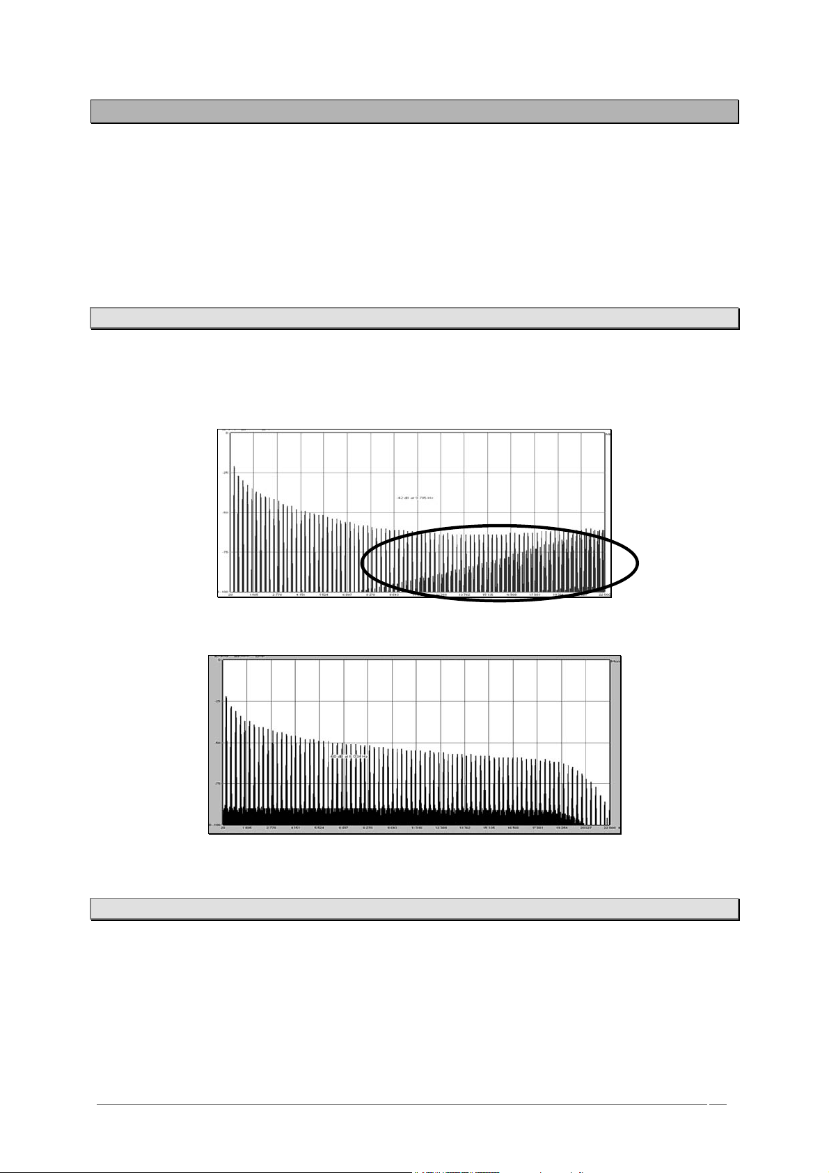
2.3.1 Aliasing-free oscillators
Standard digital synthesizers produce aliasing in high frequencies, especially when using Pulse Width
Modulation or FM.
TAE® allows the production of totally aliasing-free oscillators in all contexts (PWM, FM…), without
extra processing costs.
Linear frequency spectrum of an existing well-known software synthesizer
Linear frequency spectrum of the ORIGIN oscillator made with TAE
2.3.2 A better reproduction of analog oscillator waveforms
The waveforms produced by the oscillators in analog synthesizers are marked by the presence of a
capacitor in the circuits. The discharge of the capacitor results in a light bend in the original
waveform (notably on sawtooth, triangular and square waveforms). TAE® allows the reproduction of
this capacitor discharge. Below is the analysis of a waveform from one of the original instruments
that ARTURIA’s software emulates, and that of the Origin. Both are equally deformed by the
distortion caused by the capacitor discharge.
ARTURIA – ORIGIN – USER’S MANUAL 12
Page 13
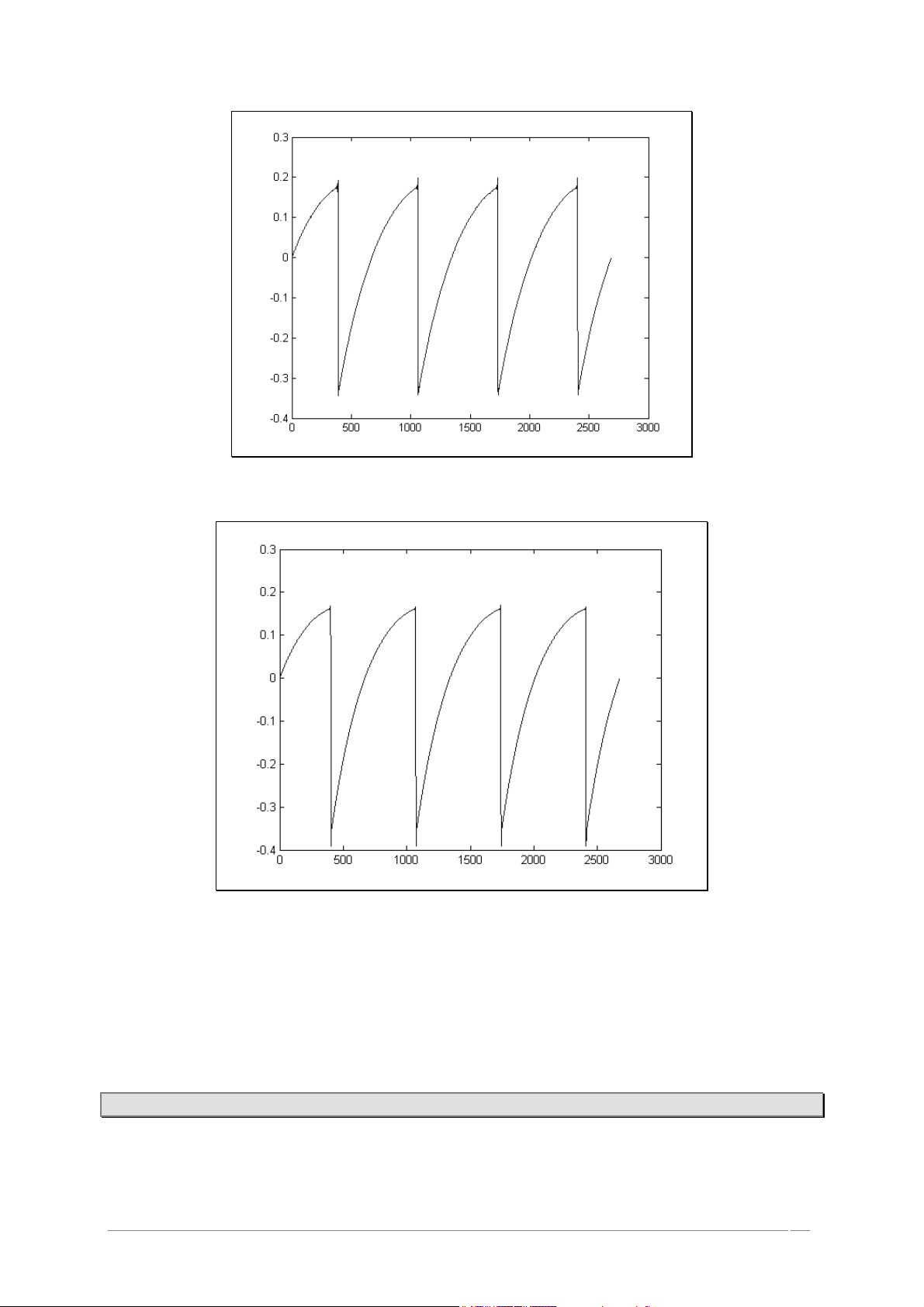
Temporal representation of a “sawtooth” waveform of an analog synthesizer
Temporal representation of a “sawtooth” waveform reproduced by TAE®
What’s more, the hardware analog oscillators were unstable. In fact, their waveform varies slightly
from one period to another. If we add to this the fact that the starting point for each period (in
Trigger mode) can vary with the temperature and other environmental conditions, we find one of
the characteristics that contributed to the typical sound of vintage synthesizers.
TAE® reproduces the instability of oscillators, bringing a fatter and “bigger” sound.
2.3.3 Direct filter circuit modeling
Due to advances in DSP processing power, Origin can now employ direct filter modeling techniques
to achieve unprecedented accuracy in the emulation of a hardware synthesizer’s filter. By modeling
the operation of the individual hardware components of the filter circuit, the warm nuances
ARTURIA – ORIGIN – USER’S MANUAL 13
Page 14
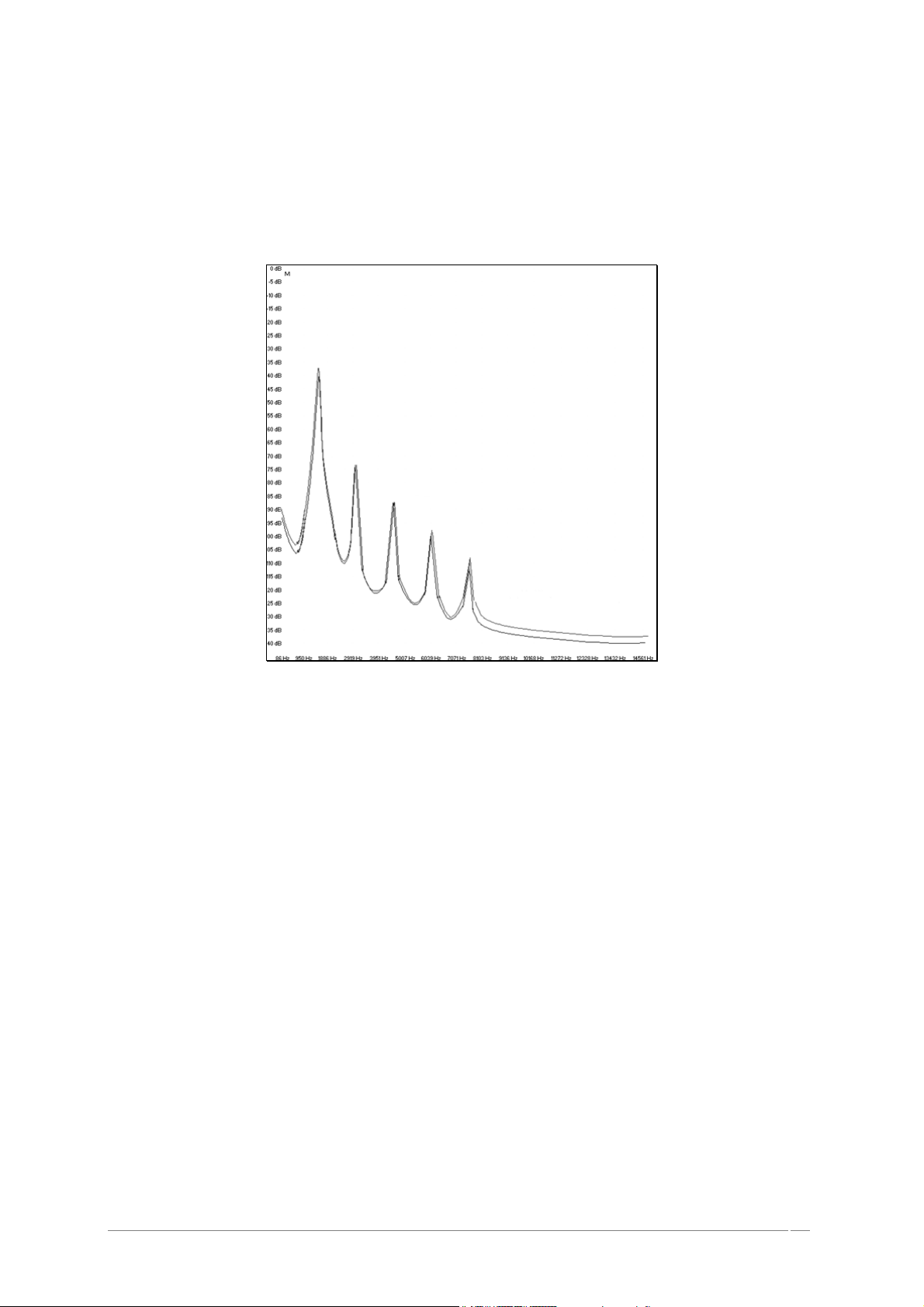
synonymous with analog sounds are recreated. The graph below is a frequency domain plot as just a
single example of direct circuit modeling in action; it shows the generation of harmonics at
multiples of the resonant frequency when the filter is in self-oscillation mode, for both one of
ARTURIA’s virtual instruments and the one it is emulating. These harmonics are characteristic for
analog filters and are due to the non-linear behavior inherent to its analog circuitry. The harmonics
generated add to the richness and warmth of the sound produced by the filter. As a result of the
direct recreation of this analog circuitry, the same characteristics of the sound are present, thus
giving the user a truly analog sound.
Comparison of harmonics generated by the filter circuits of the ORIGIN and a hardware synthesizer when
in self oscillation
ARTURIA – ORIGIN – USER’S MANUAL 14
Page 15
3 HARDWARE SETTINGS
3.1 How to put the Origin synthesizer in a rack.
The Origin synthesizer has been imagined to be used as a desktop unit but you can also put it in a
rack, if you wish. (This requires 6 empty rack units)
To do this:
Unscrew the two wood sides and the hand rest of the instrument
Screw the Origin’s ears into a rack cabinet
Unscrew the two wood sides and the hand rest
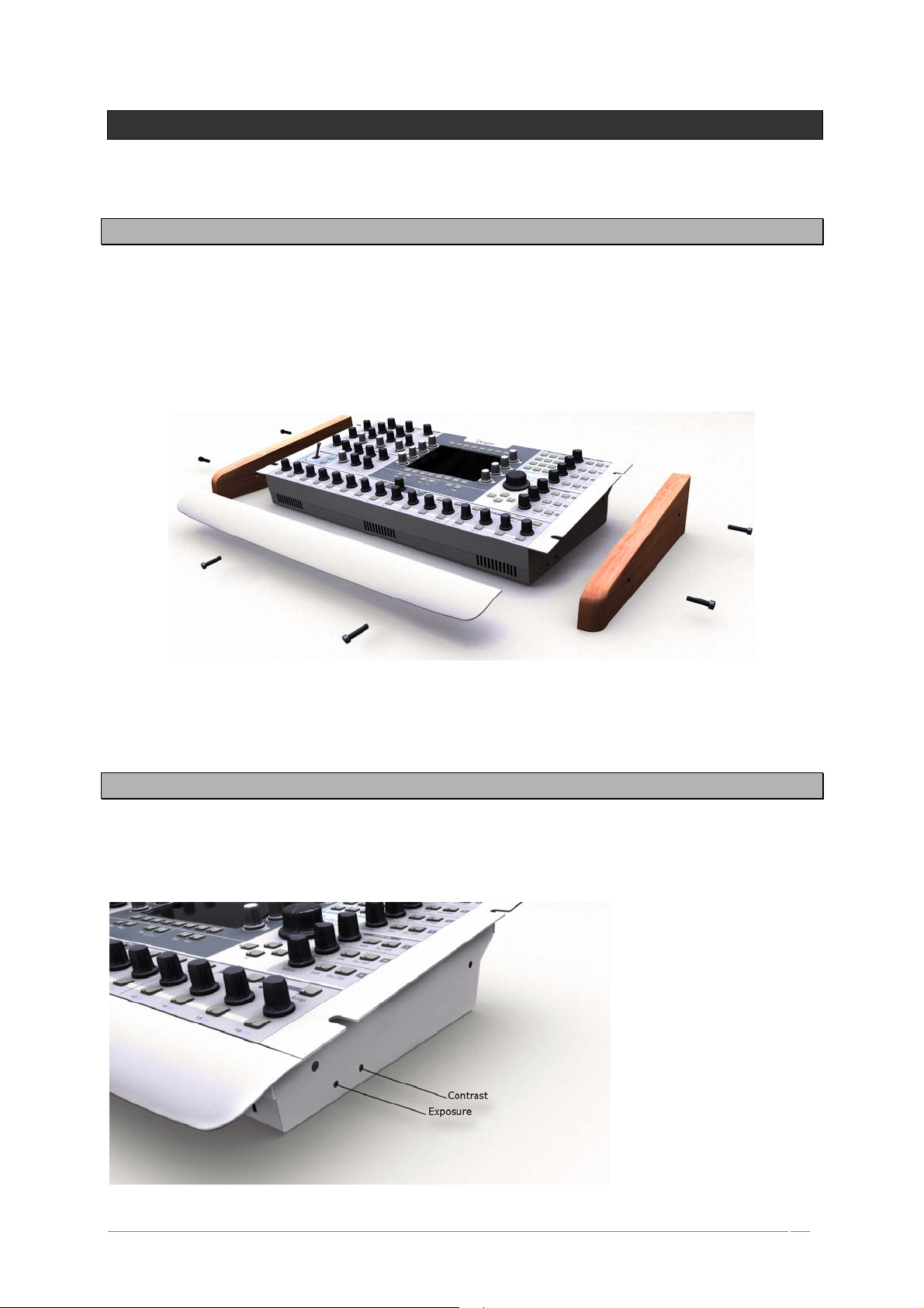
3.2 How to set the screen orientation.
As the Origin synthesizer can be used in various work conditions (on stage, on a rack, on a table,
etc.) you can set the exposure and the contrast of the screen for a more convenient visualization
and use.
Unscrew the right
wood sides;
Set the left screw for
the exposure;
Set the right screw for
the contrast.
ARTURIA – ORIGIN – USER’S MANUAL 15
Page 16
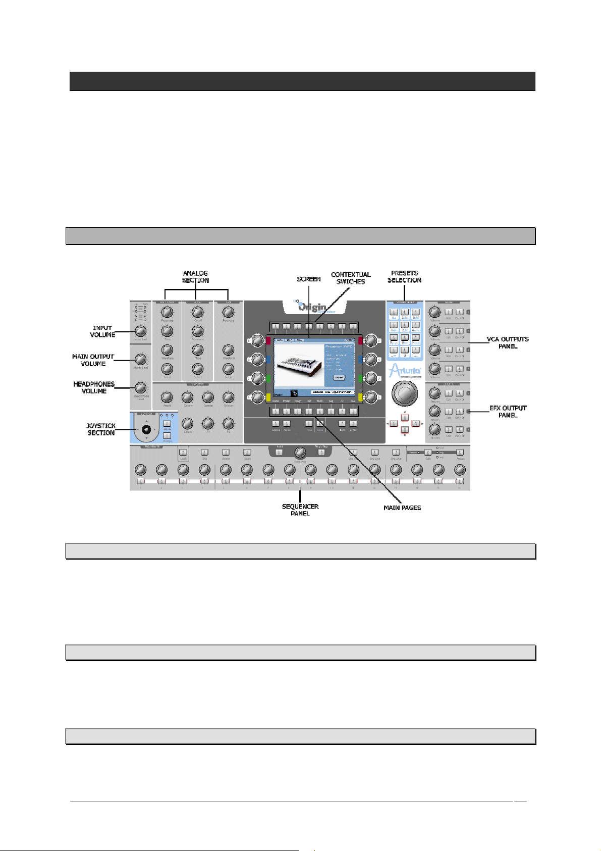
4 ORIGIN'S USER INTERFACE
This chapter explains all of the sections of Origin’s user interface as follows:
- The “Front panel” section explains the knobs and buttons of the front panel.
- The “Rear panel” section explains the input/output jacks and switches of the rear panel.
4.1 Front panel
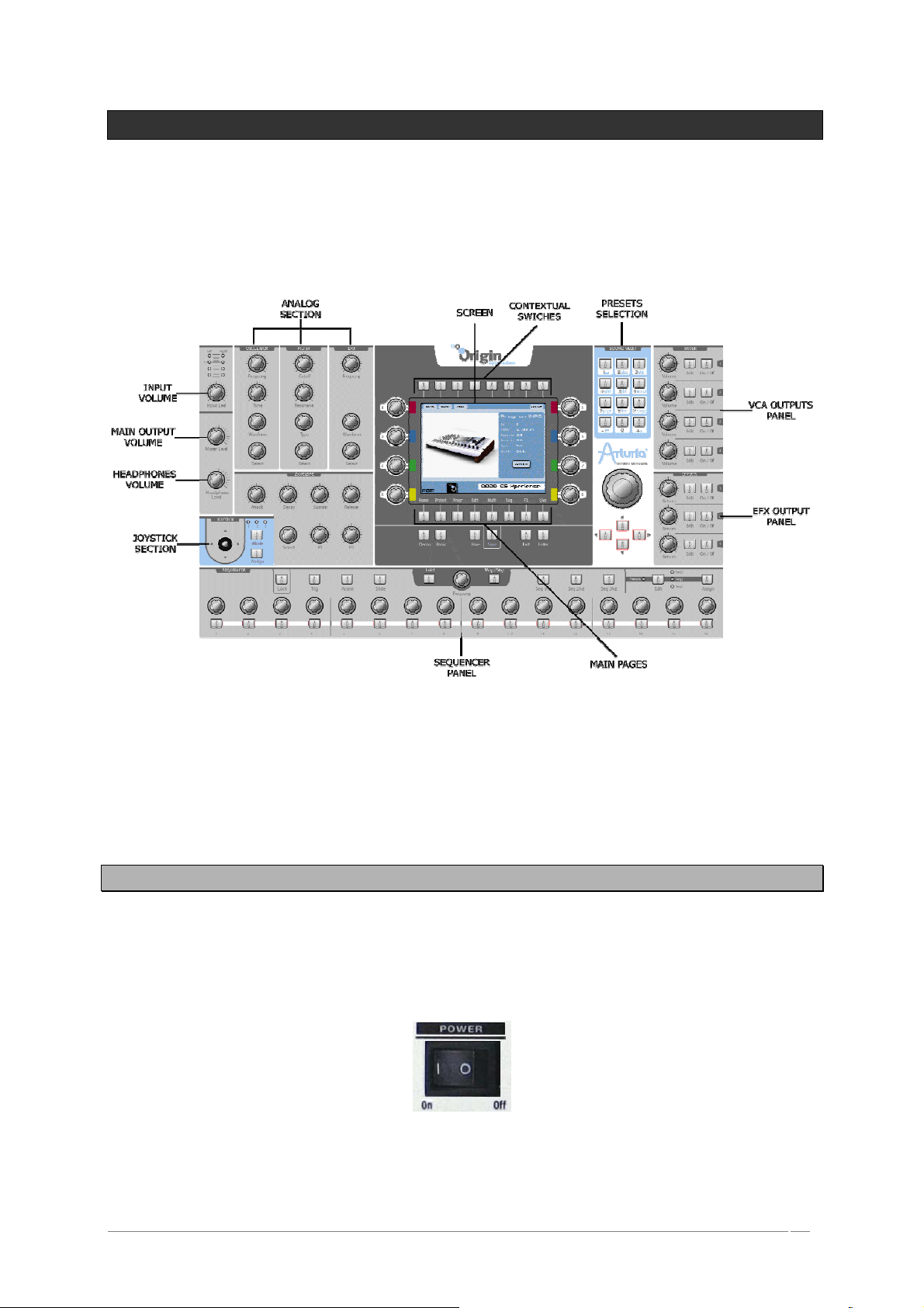
4.1.1 Output section
You can find all of the output volume controls in the output section.
- The [Master Level] knob adjusts the volume of the [Main] output.
- The [Headphones Level] knob adjusts the overall volume of the headphone output.
4.1.2 Input section
- The [Input Level] knob adjusts the input volume.
- The [Input bar graph] shows the level of the signal at Origin’s audio inputs.
4.1.3 Joystick section
- The [Joystick] controls up to four assignable parameters on its two axes Y and X.
ARTURIA – ORIGIN – USER’S MANUAL 16
Page 17

- The [Mode 1, 2, 3] button allows selection of one of three connection configurations for
the joystick.
- The [Assign] button directs you to the [Joystick] assign page.
4.1.4 “Analog” section
The “Analog” section contains all of the physical controls for the main synthesis parameters.
4.1.4.1 Oscillator section
- The [Frequency] knob controls the “Coarse” frequency of the selected oscillator module.
- The [Tune] knob controls the fine tune of the selected oscillator module.
- The [Waveform] encoder selects the waveform of the selected oscillator module.
- The [Select] encoder selects the oscillator module to edit in the current [Program]
preset.
4.1.4.2 Filter section
- The [Cutoff] knob controls the cutoff frequency of the selected filter module.
- The [Resonance] knob controls the resonance amount of the selected filter module.
- The [Type] encoder selects the filter type of the selected filter module.
- The [Select] encoder selects the filter module to edit in the current [Program] preset.
4.1.4.3 LFO section
- The [Frequency] knob controls the frequency of the selected LFO module.
- The [Waveform] encoder selects the waveform of the selected LFO module.
- The [Select] encoder selects the LFO module to edit in the current [Program] preset.
4.1.4.4 Envelope section
- The [Attack] knob controls the attack time of the selected envelope module.
- The [Decay] knob controls the decay time of the selected envelope module.
- The [Sustain] knob controls the sustain level of the selected envelope module.
- The [Release] knob controls the release time of the selected envelope module.
- The [Select] encoder selects the envelope module to edit in the current [Program] preset.
- The [Time] knobs controls the pre-decay time of the selected envelope module.
- The [Level] knob controls the pre-decay level of the selected envelope module.
NOTE: The CS-80 uses some specific parameters for its filter envelope: the “Initial level” and the
“Attack Level”. These two parameters can be controlled by the [Time] and [Level] envelope knobs.
(See the “Modules Description” Chapter 10 for more details)
4.1.5 “Screen” section
In this area you can find the LCD screen and its dedicated pages, buttons and features.
ARTURIA – ORIGIN – USER’S MANUAL 17
Page 18

- The LCD screen shows you all of the edit features included in the Origin synthesizer.
All features are organized on eight main pages for a more convenient access to
functions and parameters.
- Directly below the LCD screen you can find the “main pages” buttons. These
buttons take you directly to the corresponding page (labeled directly above) for
direct access to Origin’s parameters. The eight buttons are labeled [Home],
[Preset], [Progr], [Edit], [MULTI], [Seq], [FX] and [Live].
- Directly above the LCD screen you can find the “contextual” buttons. The function
of these buttons depends on the selected main page. For their exact function within
a specific page please refer to the page reference in this manual.
- The [Demo] button takes you directly to the Demo page to listen to Origin’s demo
songs.
- The [Panic] button stops all currently playing notes (in case of a critical problem or
malfunction).
- The [Fine] button toggles between normal (off) and fine tune mode (on). In fine
tune mode the “data dial” and the screen encoders have a more precise scale to
allow very precise fine tuning of parameters.
- The [Save] button opens the [Save/Save as] page.
- The [Exit] button exits from a screen section, menu or pop-up box.
- The [Enter] button confirms a selection or edited value.
4.1.6 [Sound Select] section
In this area you can find the dedicated features and controllers for preset and value selection.
- The key pads [0…9/abc…] allow the selection of presets by numbers or cycling
through letters for creating a new preset’s name.
- The jog dial allows selecting a preset in the [Home] or [Preset] pages. More
generally, this dial can be used for navigation and/or adjusting parameter values.
- The cursor buttons [▲/▼/►/◄] also allow navigation within pages, screen sections
and drop down menus.
4.1.7 [Mixer] section
In this panel, you can control the volume and the activity of the four “VCA” outputs of a Program
preset as well as the four “Program” outputs on a “Multi” preset.
- The [Volume 1…4] knobs have two functions: in [Program] mode, they control the
volume of the respective “VCA” outputs. In [MULTI] mode, they control the four
“Program” outputs.
- The [Edit 1…4] buttons select the corresponding program preset for editing when in
multi mode. In program mode these buttons have no effect.
- The [On/Off] buttons mute the corresponding program preset when in multi mode.
In program mode these buttons have no effect.
4.1.8 [Effects] section
With this panel, you can control the return volume and the activity of the three effects outputs of a
Program preset.
ARTURIA – ORIGIN – USER’S MANUAL 18
Page 19
- The [Volume 1…3] knobs control the return volume or dry/wet balance of the three
effects. (For more details, refer to chapter 7.3.2)
- The [Edit 1…3] buttons jump directly to the “Fx1…3” slot on the [Effect] page.
- The [On/Off] mute or bypass the selected effect. (For more details refer to chapter
7.3.2)
4.1.9 [Sequencer] section
In this panel, you can find all of the real-time controls concerning the sequencer.
- The [Play/Stop] button toggles the step sequencer on or off. When set to on, the
step sequencer starts running when a note is pressed and stops when the last note is
released.
- The [Hold] button toggles hold on or off. When hold is on, are active and new notes
are held until the hold button is switched off again.
NOTE: You can also use this function when the sequencer is not playing.
- The [Seq1…3 Act] buttons activate or deactivate sub-sequence 1…3.
- The [Edit> Seq1… Seq3, Pattern] button selects the corresponding sequence for
editing or, when [pattern] is selected, activates pattern selection mode.
- The [Assign] button opens the “assign” pop-up of the selected sub-sequence.
- The [Hold] button locks the currently playing sequencer step. The sequencer is
stopped and keeps sending its current modulation values until the lock button is
pressed again.
- The [Trig] button activates the key trigger on the current step of the selected sub-
sequence.
- The [Accent] button triggers the accent envelope on the current step of the
selected sub-sequence.
- The [Slide] button activates the slide function on the current step of the selected
sub-sequence. It changes smoothly from the current value to the value of the next
step in the sequence.
- The [1…16] encoders set the value of step 1…16 (or 17…32).
- The [1…16] buttons have two functions: in [Edit Seq1…3], they select step 1…16 (or
17…32). In [Pattern] selection mode, these buttons select a pattern preset 1…16.
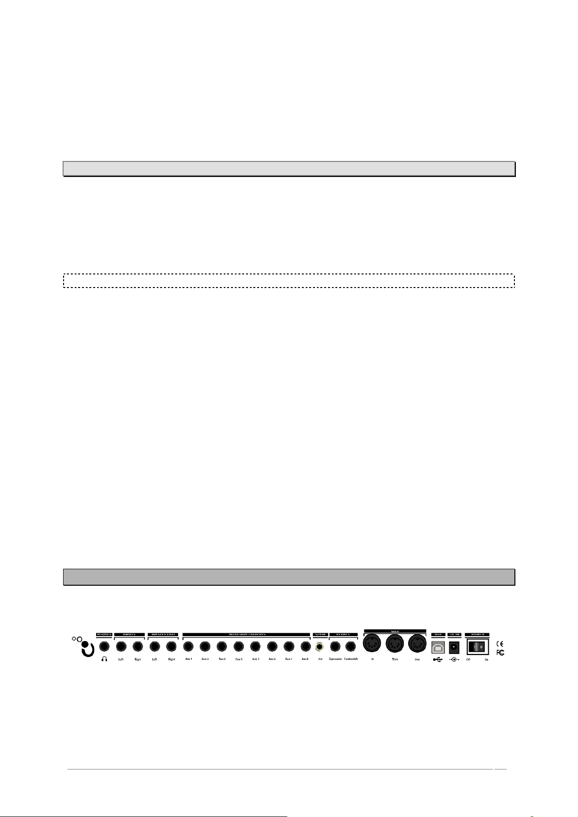
4.2 Rear panel
On this panel, you can find all the power, audio and MIDI connections.
From right to left you can see:
- The [Power] button allows to turns the power on/off.
- [DC IN] Connection for the included AC/DC 6.5V power adaptor.
- [USB]: Input for connection with a computer. It can be used for MIDI IN and OUT
communications or for data transfer (e.g. preset dump, software updates…)
ARTURIA – ORIGIN – USER’S MANUAL 19
Page 20

NOTE: The USB interface provides multi-port MIDI operations which are not available with a classic
single MIDI connection.
- [MIDI In/Out/Thru]: Connectors used for the MIDI communication with other MIDI
devices:
- [In]: receives MIDI data from another device. Connect this to another device's MIDI
Out (or Thru).
- [Out]: sends MIDI data to another device, connect this to another device's MIDI In.
- [Thru]: sends thru MIDI data received at the [MIDI In] port. This allows you to
“chain” multiple MIDI devices.
- [Footswitch]: Pedal input. Works with any standard, normally open or normally
closed momentary footswitch. It is usually used for sustain pedal controller.
- [Expression]: Pedal input. This input can be connected to a standard expression
pedal.
- [Auxiliary outputs 1-8]: These eight audio auxiliary balanced outputs are
independent of the [MAIN] audio outputs. This way, you can process each of the
program outputs in multi mode separately.
- [Master out L/R]: Origin's main balanced stereo outputs.
- [Inputs L/R]: These connectors are mainly used to connect external audio devices
(CD player, synthesizers, etc.) so they can be processed through Origin’s filters and
effects.
- [Headphones]: ¼ inch stereo headphone output.
ARTURIA – ORIGIN – USER’S MANUAL 20
Page 21
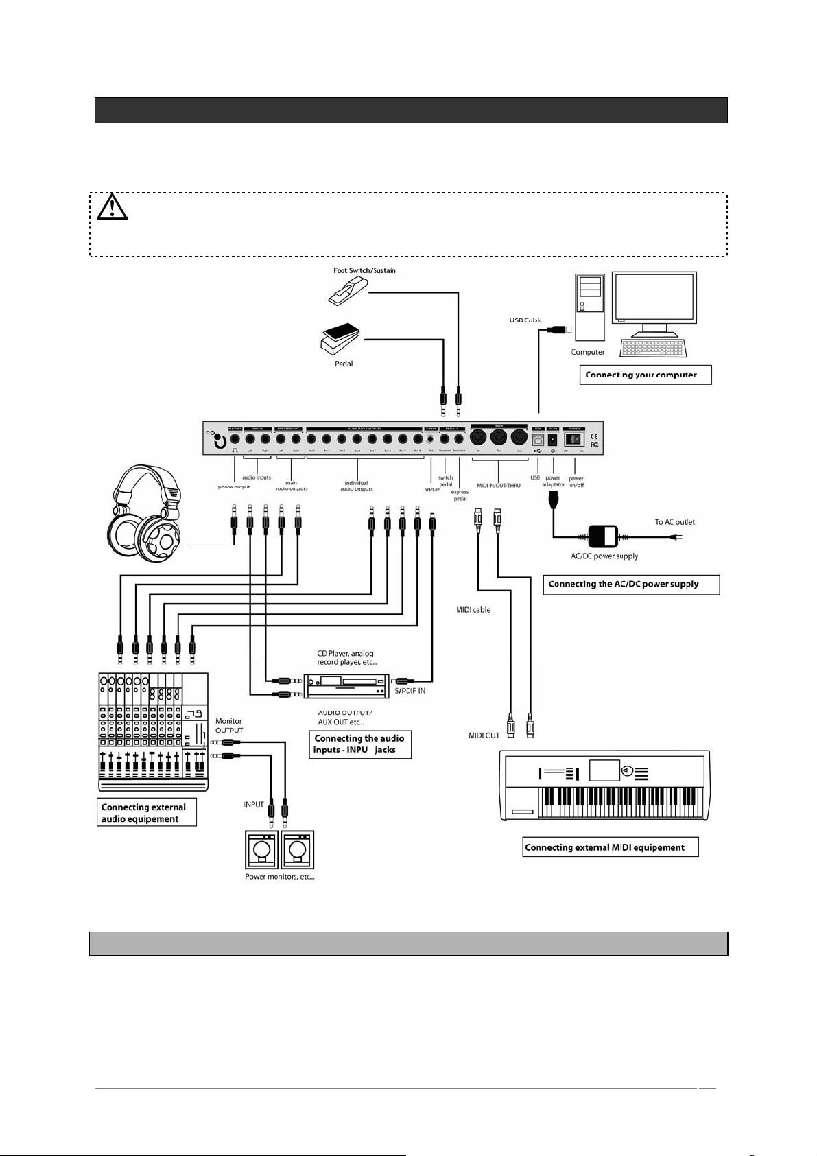
5 CONNECTIONS
WARNING! Make all your audio connections with the power off (on all units!). If you don’t,
you may damage your speakers, the Origin synthesizer or other audio equipment. Please use
caution.
5.1 Connecting the AC/DC power supply
Connect the included AC/DC power supply to the Origin synthesizer. After you’ve connected the
AC/DC power supply to Origin, plug it into an AC outlet.
ARTURIA – ORIGIN – USER’S MANUAL 21
Page 22
5.2 Connecting Origin to headphones
Connect your headphones to Origin’s [Phones] output. You can set the headphones output volume.
5.3 Connecting the Origin’s analog outputs to external audio equipment
5.3.1 [Main Outputs]
Connect Origin’s 1/4 inch output jacks [MAIN Outputs] to your audio equipment (e.g., mixer or
powered monitors).
Using these outputs, you can hear the main outputs of the program (using the [Program] mode) or
the main output of the multi mixer (using the [MULTI] mode).
NOTE: Because there is no distinction between the two [Main Outputs] balanced jacks, you can use
any of those outputs to when you are playing a mono sound
5.3.2 [Auxiliary Outputs]
In [MULTI] mode:
- the output of channel 1 of the Multi mixer is connected to the [Auxiliary Outputs] 1 and 2;
- the output of channel 2 of the Multi mixer is connected to the [Auxiliary Outputs] 3 and 4;
- the output of channel 3 of the Multi mixer is connected to the [Auxiliary Outputs] 5 and 6;
- the output of channel 4 of the Multi mixer is connected to the [Auxiliary Outputs] 7 and 8.
In [Program] mode, the main stereo outputs of the program are directed to the [Auxiliary Outputs]
1 and 2.
NOTE: To take full advantage of Origin’s capabilities, we recommend that you output in stereo.
5.4 Connecting Origin to digital audio equipment
You can connect Origin’s [SPDIF] output to your digital audio equipment (e.g. digital mixer).
NOTE: The digital audio input of your destination device (computer audio interface, D/A
converter, etc) may require that you set the SPDIF input as the master clock source in order to
hear the sound coming from the Origin. Consult your interface/device user’s manual of for more
information.
5.5 Connecting pedals and switches
Two jacks ([EXPRESSION] and [FOOT SWITCH]) are provided so that you can connect both a foot
switch and an expression pedal (both sold separately) to Origin for additional control.
ARTURIA – ORIGIN – USER’S MANUAL 22
Page 23

5.6 Connecting external MIDI equipment
Origin can be used as a multitimbral MIDI sound module, or as a controller for other MIDI
equipments.
5.6.1 Using Origin as a sound module
If you are using Origin as a sound module, use a MIDI cable to connect Origin’s MIDI IN connector to
the MIDI OUT connector of your external MIDI device.
5.6.2 Using Origin as a MIDI controller
If you want to control an external MIDI device from the Origin’s front panel, use a MIDI cable to
connect Origin’s MIDI OUT connector to the MIDI IN connector of your external MIDI device.
5.6.3 MIDI channel settings – Getting ready to play
If you’re using Origin as a sound module, you’ll need to set Origin’s global MIDI channel to match
the MIDI channel of the external MIDI device that you’ve connected.
To set Origin’s global MIDI channel:
Go to the [HOME] page and press the [System] contextual menu button;
Set the [Global MIDI channel] to the desired value using the cursors or the data dial. Confirm by
pressing the [Enter] button.
5.7 Connecting your computer
Origin provides both MIDI connectors and a USB connector.
Both can transmit and receive MIDI data in the same way. Use the type of connection that is most
appropriate for your setup.
Using the USB connection for data transfer between Origin and the computer is faster.
If you use MIDI cables to connect the Origin synthesizer to your computer, you’ll need to purchase a
separate MIDI interface of the appropriate type for your computer. For details on connecting the
MIDI interface to your computer and how to set the MIDI ports, refer to the owner’s manual for your
MIDI interface.
5.8 Connecting the audio inputs – INPUT jacks
You can connect any audio source (synthesizer, CD player, output of a mixer, etc.) to the [INPUT]
jacks. By using this connection, you can process the audio coming from this external source the
same way as Origin’s internal sound generators.
ARTURIA – ORIGIN – USER’S MANUAL 23
Page 24
6 THE ORIGIN STRUCTURE
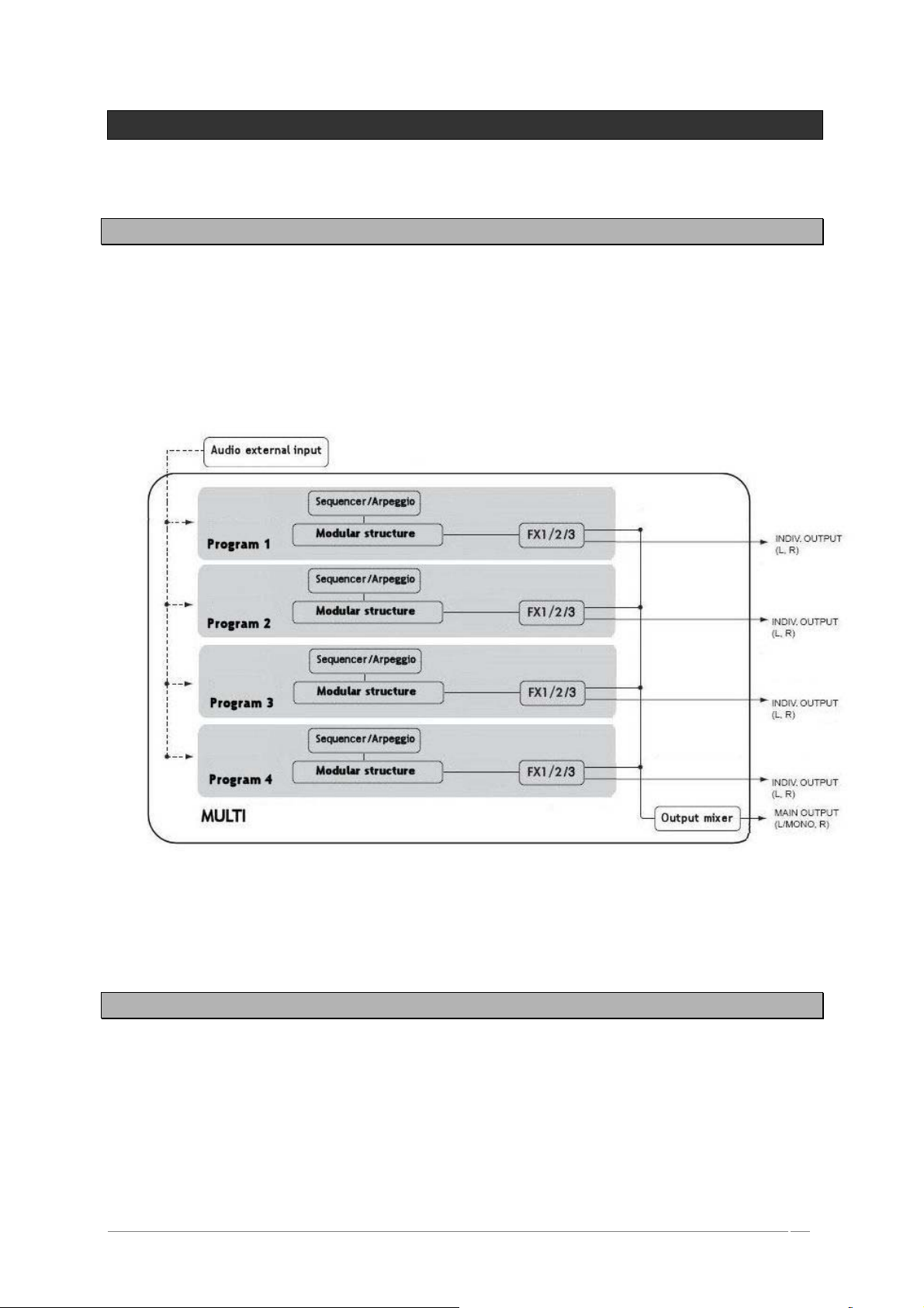
6.1 Overview of the global structure of Origin
The Origin synthesizer uses 2 different kinds of presets:
The Program preset uses a modular structure as a base of its synthesis. This modular structure
allows you to easily create new and rich sounds, sequences and effects. These program presets can
be played by the step sequencer or the arpeggiator and be connected to up to three effect slots.
The Multi preset allows you to assign up to four Programs for layering sounds, as well as to assign a
specific MIDI channel to each Program for four parts of multitimbral operation.
The global Origin architecture
6.2 The program preset
The Program preset includes the modular synthesis structure, which is the main part of the Origin
instrument. You can access this area by pressing the [EDIT] button, just below the LCD screen.
The modular synthesis structure allows venturing in one of the most powerful technology for sound
creation.
First, you can choose the basic audio modules:
ARTURIA – ORIGIN – USER’S MANUAL 24
Page 25
- Up to 9 oscillators (based on the Minimoog, ARP 2600, CS-80, Jupiter-8 and Prophet VS
synthesizers, plus a special Origin classification of sound module).
- Up to 4 mixers
- Up to 4 filters (based on the Minimoog, ARP 2600, CS-80 and Jupiter-8 filters plus a special
Origin one).
- Up to 4 independent output amplifiers (VCAs)
The modulation modules you want to connect to those audio modules:
- Up to 8 ADSR and special AR envelopes
- Up to 4 LFOs
- Up to 4 independant keyboard followers
- 1 Ring modulator
- 1 Bode frequency shifter
- 1 Keyboard trigger
- 1 Joystick
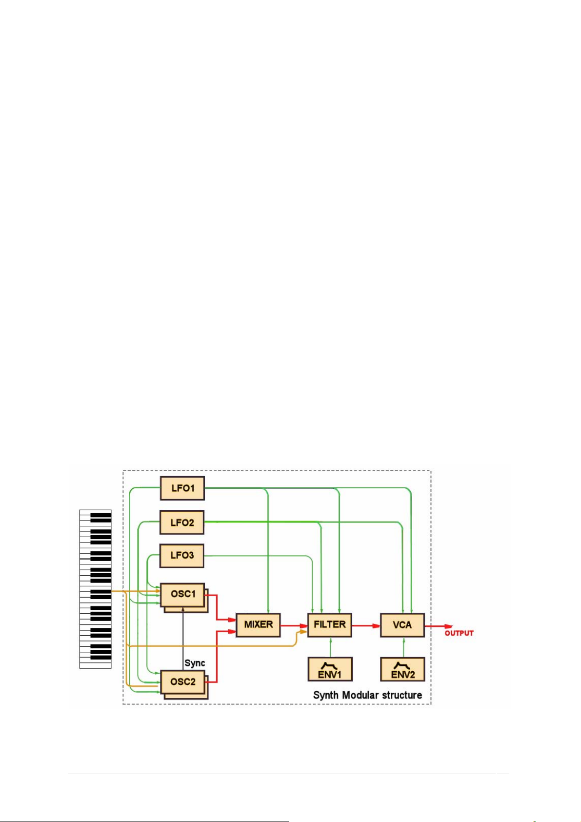
The graphically displayed preset below is an example of a basic synthesizer structure including:
- 4 oscillators (including a sync connection between the oscillators 1 and 2)
- 1 mixer
- 1 filter
- 1 VCA
- 3 LFOs
- 2 envelopes
- 1 Key follow and 1 keyboard trigger
The red lines are the audio connections, the green ones are the modulation connections and the
yellow ones are the keyboard follow and keyboard trigger connections.
A modular structure example
ARTURIA – ORIGIN – USER’S MANUAL 25
Page 26
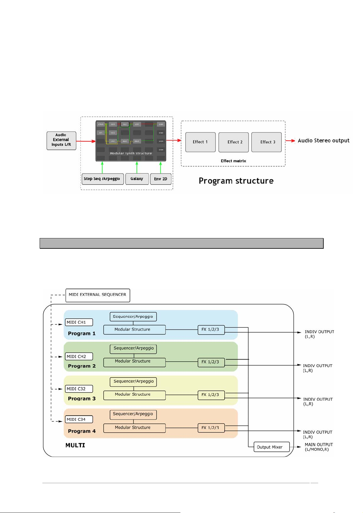
On this sound, you can add:
- Up to 3 different sequences modulating different parameters. Alternatively, you
can use the arpeggiator.
- 3 special MIDI sync LFOs using the Galaxy module
- A 5-stage looping 2D envelope
- Up to three effect units, including a stereo delay, chorus/ensemble, phaser,
distortion and reverb.
The Program architecture
6.3 The Multi preset
The Multi preset allows you to use up to four Programs simultaneously. Each program can be
assigned to a specific MIDI channel for up to four parts of multi timbral operation. Alternatively you
can assign all programs to the same MIDI channel to set up layering or keyboard-split patches.
An example using an external MIDI sequencer for a multitimbral arrangement
ARTURIA – ORIGIN – USER’S MANUAL 26
Page 27
7 QUICK START
This chapter will introduce you to the general principles of the Origin synthesizer. You will find
basic examples of the different interfaces of the synthesizer meant for first time users. A precise
and detailed description of all the parameters and controllers will be given in the following
chapters.
The complete view of Origin’s front panel
The ORIGIN synthesizer contains several demo songs, numerous programs, and a wide range of
advanced features and functions.
For a quick introduction to all this fun, follow along with this Quick Start guide.
7.1 Turning on the power and adjusting the volume
After connecting the AC/DC power adaptor, set the rear panel [Power On/Off] switch to “On”.
The start-up screen appears in the display, when the machine is ready, the [Home] page is
displayed. Each time you turn the power on, ORIGIN will be in the Program Play mode.
Turn on the other audio equipment that’s connected to ORIGIN.
Turn the power “On”
ARTURIA – ORIGIN – USER’S MANUAL 27
Page 28
NOTE: When you’re ready to turn the power off, first decrease the main volume of the connected
equipment to 0 (e.g. an external audio mixer), then press the [ON/OFF] switch on the ORIGIN’s
rear panel to turn off the power.
7.2 Adjusting the volume
Begin with the [Main Level] knob fully rotated to the left-most position. Play a few notes on the
keyboard and gradually raise the volume to an appropriate level.
If you are using headphones, connect them on the [Headphones] jack, on the rear panel and
adjust the [Headphones Level] knob.
Set the volume to an appropriate level
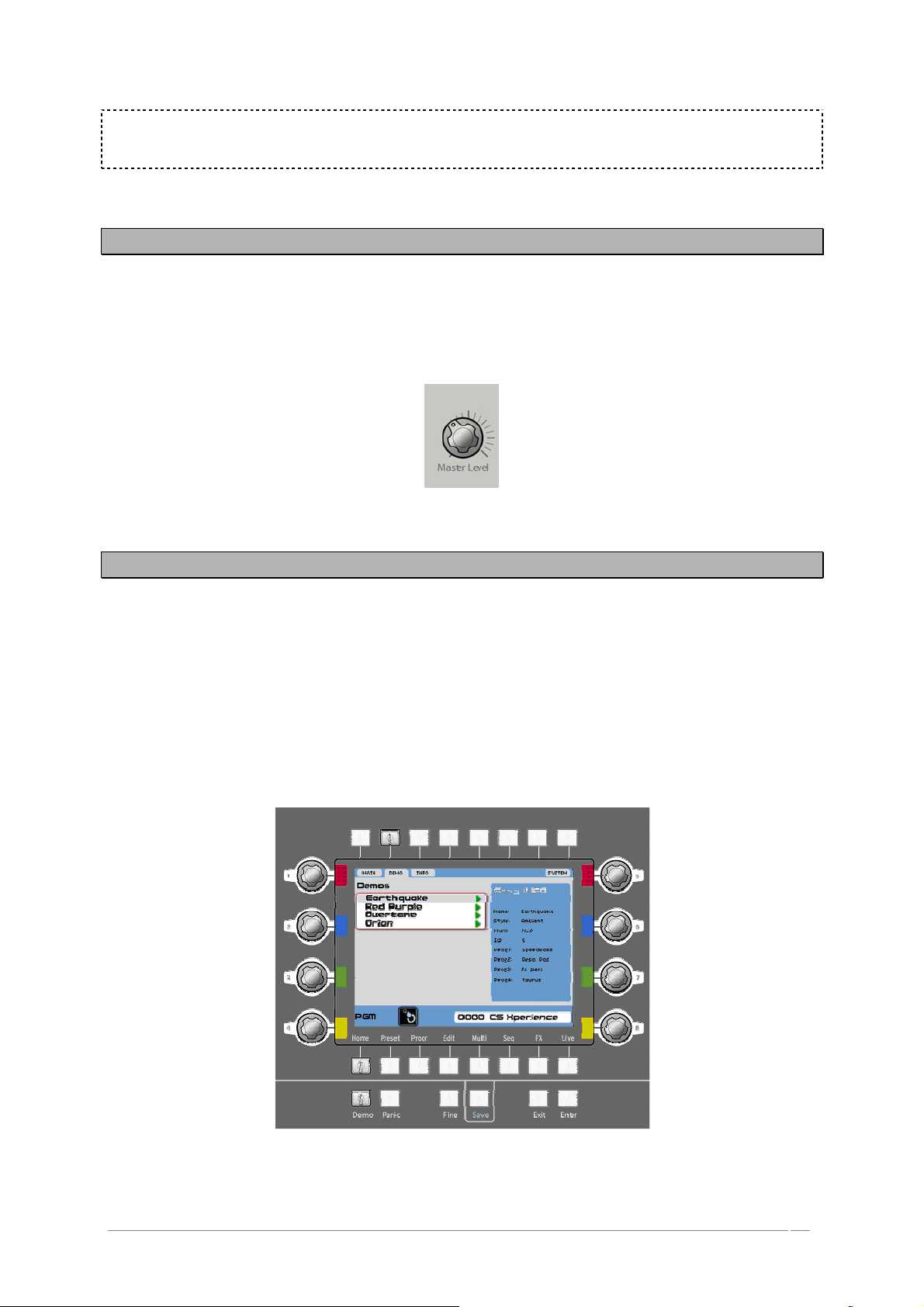
7.3 Demo playback
ORIGIN contains several demo songs that take advantage of its rich sounds and expressive potential.
On the [Home] page, press the [Demo] contextual button (located in the top of the central
screen) to go to the Demo page.
Use the jog dial to select the first demo song [“Earthquake”] and press this dial (or press the
[Enter] button) to start the song.
To stop the song, press the jog dial (or press the [Exit] button).
You can select another song using the jog dial or the cursor buttons. To listen to it, follow the
steps above.
Select the demo song
ARTURIA – ORIGIN – USER’S MANUAL 28
Page 29
7.4 Playing Program presets
The presets allow you to choose synthesis parameters as well as the player settings (“Unison” mode,
monophonic, polyphonic…), sequencer, effects parameters and more with a single selection.
In Origin, a Program contains all the parameter settings of the synthesizer, the various real-time
controllers configuration (ex: velocity, aftertouch, pitch-bend, controller assignments…) as well as
the effects and the sequencer settings necessary to reproduce the sound.
Origin is delivered with 400 factory Program presets that allow you to become acquainted with the
sounds of the synthesizer. A bank named “User/ Temp” offers a selection of presets giving the
possibility to use a template to begin programming a sound. The sound “1_Osc”, for example, is
presented with: an oscillator connected to a low pass filter, which is routed to the VCA.
To become more familiar with the various sounds offered in Origin, we are going to select the
preset n°050, named “Reso_Pad”.
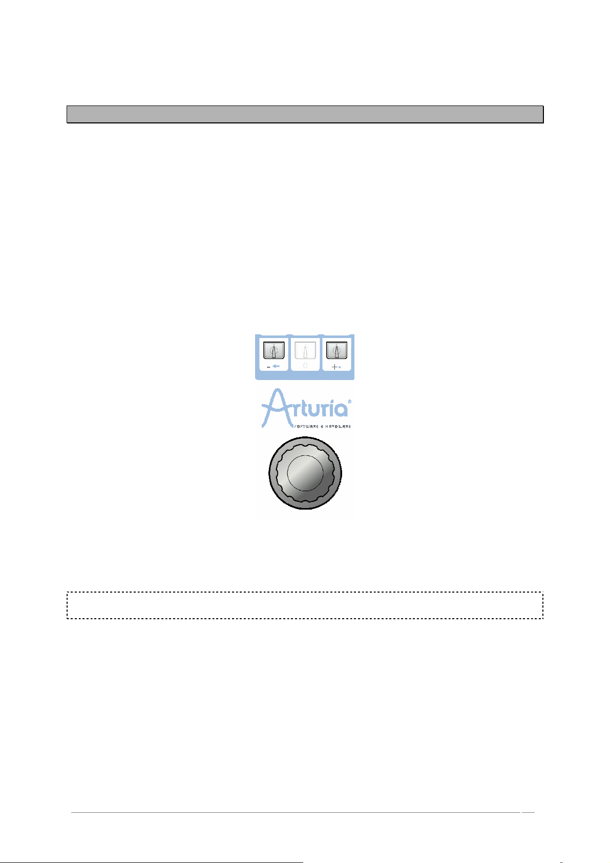
Remaining on the [Home] page, select the number “0001” by turning the jog dial or using the
“+” or “-“buttons, located in the [Sound Select] section.
Select the preset on the [Home] page, thanks to the jog dial.
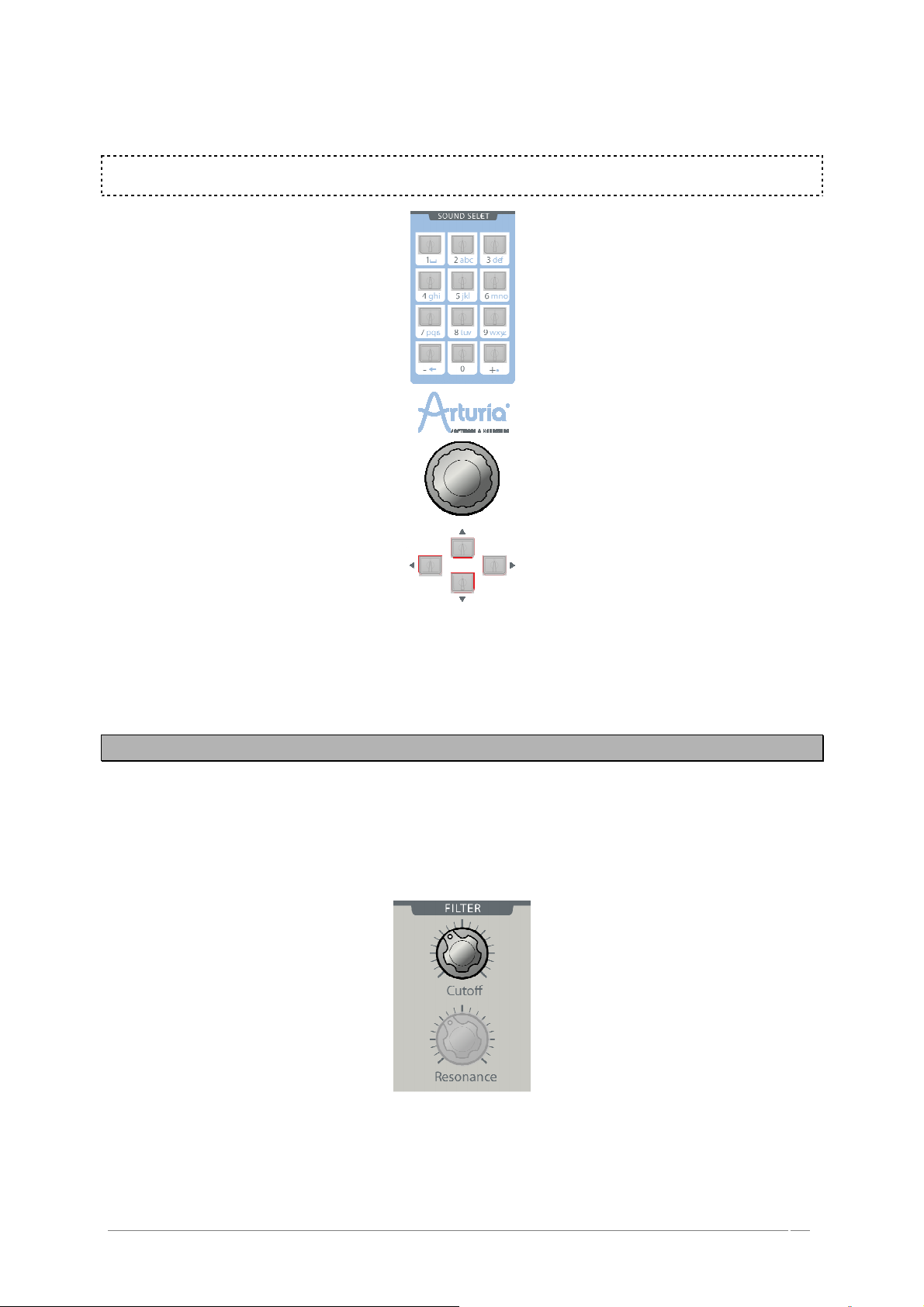
Alternatively, you can type the numbers manually using the numeric key pad in the [Sound
Select] section.
NOTE: For listening to the current preset before loading, you can use the [Preview] option. To do
this, press the jog dial to start the preview.
When you press the [Preset] button, the [Preset] page displays. It displays a list of all the presets
and details of the currently selected preset. Above the preset list there are two drop down menu’s
labeled [Key 1] and [Key 2]. Here you can select search criteria to filter out sounds that do not
match your criteria. This way you can quickly find the sounds you need. We’ll select the “Reso Pad”
using the search criteria.
Press exit to navigate through the preset page and use the jog dial or “cursors” to scroll to [Key
1]. Press the jog dial or the [Enter] button to select it.
On [Key 1], choose the criteria [Sound Designer]. Upon selecting a sound designer, only his (her)
sounds is displayed. We’ll choose [JMB].
Following the above steps, select [Key 2] and choose [Type]. Here you can select which types of
sounds are displayed. We’re looking for a pad, so we’ll scroll down to choose [Pad].
ARTURIA – ORIGIN – USER’S MANUAL 29
Page 30
The “Reso Pad” (among others) displays in the preset list as matching the criteria. Highlight it
using the jog dial or cursors and select it by pressing the jog dial or the [Enter] button.
NOTE: You can also use the [▲/▼] buttons, situated above the wheel to go through the different
presets
Select the preset on the [Preset] page, thanks to the key pad
7.5 Editing the preset
To edit a preset, we are going to start with a basic example.
Edit the brightness of the “Reso_Pad” sound with the [Cutoff] knob of the filter. To do this, turn
the knob located in the [Filter] slot, on the “Analog section”, to the right or the left. The timbre of
the sound becomes more or less bright. Change the knob to your liking.
Change the cutoff of the sound
In the same way, you can increase or decrease the frequency of oscillator 1 by turning
[Frequency] knob on the [Oscillator] panel. To adjust the frequency of oscillator 2 turn the [Select]
ARTURIA – ORIGIN – USER’S MANUAL 30
Page 31

encoder on the same section so that the screen pop-up displays [Osc 2 – Coarse Tune …]. Press the
encoder to validate your choice. Now the [Frequency] knob (actually the entire [Oscillator] section)
is assigned to oscillator 2.
Setting the frequency of oscillator 1
NOTE: You can set the volume of the four VCAs directly with the [Volume] knobs located in the
[Mixer] panel, on the right of the Origin interface. In this area, you can also directly mute their
activity by using the [ON / OFF] switches.
7.6 Saving your Program
By making just a few modifications, you have already edited the Program “Reso_Pad”. You can now
save the sound you’ve just created. Origin allows you to create up to 600 User Programs.
Their numbers begin at 400 and proceed to 999.
To choose another destination number for the sound, simply click the [Save] button. This button
is located in the bottom of the central screen, under the Pages buttons.
Press the [Save] button
Then, choose its location. For example, select the number [600]. The name [-EMPTY-] appears
on the screen.
Press on the jog dial and select the rename area.
Press the key pads them as you wish in the three sections.
ARTURIA – ORIGIN – USER’S MANUAL 31
Page 32

Saving as a preset
To save a “User” preset, click on the “Save” icon in the tools bar: the new settings are saved in
the preset currently selected without changing the name (if the preset being edited is part of the
factory presets, the factory settings will not be deleted).
WARNING! It is important to realize that changing the name of a preset does not create a new
one! Only the name of the preset being edited is modified.
7.7 Add a module to your preset
Origin is a modular synthesizer which means that it allows you to build your own synthesis structure.
You can do this by adding different modules into a virtual RACK and make all the needed
connections between them to make your sound. This way, you will explore one of Origin’s most
interesting features, allowing you to create an infinite variety of sounds.
To have access to these features, go to the [Edit] page by pressing the button of the same name
under the LCD screen. The [Edit] page displays all the modules that make up the currently selected
program.
The [Edit] page offers two different interfaces: [RACK] and [PATCH]. You can toggle between them
using the rightmost button above the LCD screen.
The [RACK] interface is very basic: it shows a basic layout of all the modules that make up a
program without their connections.
The [RACK] view
The [PATCH] interface shows the synthesis diagram with all used modules with their audio,
modulation and trigger’s connections. It is the best way to a global view of your sound construction.
ARTURIA – ORIGIN – USER’S MANUAL 32
Page 33

The differences between these two interfaces are only graphical, they share the same functionality.
Both can be used to create your own synthesis structure and you can always toggle between them.
Let’s take the [RACK] interface to add a new oscillator to our current program.
Press the [Add] Button to open the modules choice menu. Choose the option [Oscillator], press
the jog dial and choose the [Minimoog] oscillator.
Open the module interface by pressing the jog dial. As mentioned in the name of the module
itself, it shows a Minimoog oscillator like interface.
Select the [FM] slot on the right panel by using the [►] arrow, under the jog dial and select the
[Add Connection] > [Keyboard Follow] > [Audio 1] option. In this way, the pitch of the oscillator
follows the keyboard range.
In the same way, go to the [Outputs] slot and choose the [Minimixer 1] > [Audio 1] option. The
audio output of the oscillator will be connected to the mixer.
You can set the range and the pitch of the oscillator by selecting the [Range], [Coarse] or [Fine]
parameters with the dedicated knobs, on the [Oscillator] panel of the “Analog” area.
You can set the audio input mix of the three oscillators by opening the [Minimixer 1] module. To
do this, select the desired [Gain 1, 2 or 3] knob by using the [▲/▼] arrows or turn the jog dial to
set the dedicated volume.
Finally open the [PATCH] interface, the following synopsis displays our example sound creation for
this preset:
The [PATCH] interface
7.8 Using the Minimoog template
Instead of making your own modular structure, you can also use the synthesizers templates included
in the machine. This way you can start playing and tweaking straight away.
To load the Minimoog template, go to the [Preset] page. On the top left of the page you can
find three page tabs; [PGRM], [MULTI] and [NEW].
Press the contextual button situated directly above [NEW].
On the [NEW] tab you can open different synthesizer templates, for this quick start we will use
the Minimoog template.
ARTURIA – ORIGIN – USER’S MANUAL 33
Page 34

Select a new Minimoog template preset
Select the Minimoog using data dial or the cursors, then press the data dial or the enter button.
You are now redirected to the edit page which displays a basic representation of the original
Minimoog. Before we dive into the features accessible though the LCD screen, let’s just play the
template first using the dedicated hardware buttons.
The Minimoog template interface
There is already a sound loaded so you can start playing straight away.
To modify the sound a bit more to our personal taste, try turning the [Cutoff] and [Resonance]
knobs on the [Filter] section of the “Analog Section”, on the front panel.
ARTURIA – ORIGIN – USER’S MANUAL 34
Page 35

Turning the [Cutoff] and [Resonance] knobs on the [Filter] section
After that you can tweak the oscillator using the dedicated [Oscillator] section next the [Filter]
section.
Using the [Waveform] encoder, you can browse through the different waveforms offered by the
Minimoog.
The waveform knob only influences oscillator 1 however, and we’d like to be able to control the
other oscillators using the hardware knobs as well. To do this, turn the [Select] encoder on the
[Oscillator] section. This way you can browse through the different oscillators to select them for
editing. When the LCD screen displays the oscillator you wish to edit, press the [Select] encoder.
Now the hardware knobs in the [Oscillator] section are assigned to the oscillator you’ve just
selected.
When the overall sound is the way you want it to be, you can start shaping its amplitude and
spectrum over time using the [Envelope] section. By default, the amplitude envelope is selected for
editing.
To change this, turn the [Select] encoder in the [Envelope] section. When the LCD screen
displays the envelope you want to edit, press the [Select] encoder.
ARTURIA – ORIGIN – USER’S MANUAL 35
Page 36

Now we will use some of the features included in the template which are not found on the original
Minimoog. We will modulate the filter frequency using the velocity so that when we strike a key
hard, the sound will be brighter.
To do this, go to the [Edit] page where the Minimoog interface is displayed and browse through
the different sections using the jog dial or the cursors.
The Filter settings
Go to the [Modulation Matrix] section and press the data dial or the [Enter] button. You will be
presented with a pop-up allowing you to route 8 different modulation sources to 8 different targets.
Using the jog dial, move to the left slot of the upper row and press the data dial. From the pop-
up menu, select the [Velocity] control. Now go to the right slot of the upper row and select [Cutoff]
using the same method.
Select the velocity modulation source
The knob in the middle allows you to change the amount of the modulation.
ARTURIA – ORIGIN – USER’S MANUAL 36
Page 37

Set the velocity modulation amount
Set it around 3 o’clock. Now the filter opens up more as you play louder on your keyboard, this
makes your sound more dynamic and lively.
Feel free to explore the other possibilities offered by the modulation matrix to create your own
unique sounds.
7.9 The [MULTI] mode
The [MULTI] mode allows you to use up to four programs on separate MIDI channels. Alternatively
you can layer up to four programs, or use a combination of both (using no more than 4 programs).
To add some “breath” to our current preset (“Reso_Pad” preset n°0050), we’ll use the [MULTI]
mode to layer it with a flute.
Open the [MULTI] page by pressing the [MULTI] button, under the LCD screen.
On the first mixer slot, the current sound is “Reso_Pad”. Select the second slot by using the
button and press the “value” dial. A pop-up screen appears asking you to transform the current
“►”
preset in a [MULTI] preset.
Press “Enter” to confirm the creation of the [MULTI] preset.
Select the preset n°053 named “Cosmology” on the second mixer slot by pressing on the jog dial
and using the [▲/▼] arrows. Press the jog dial another time to validate this choice.
The new [MULTI] preset
ARTURIA – ORIGIN – USER’S MANUAL 37
Page 38

Now, the “Cosmology” preset plays with the “Reso_Pad” in a layering fashion.
You can now set the volume of this new layer by turning the second [Volume] knob, on the
[Mixer] panel.
Set the volume of the second layer
Now you can save your new [MULTI] preset by pressing the [Save] button and follow the same
steps than saving a Program preset (see chapter 1.6 for more details).
7.10 Using the step sequencer
Each sequence used in a program consists of three sub-sequences which can be used to modulate
different parameters. This way, you can easily set up complex sequenced modulations, all
controlled hands-on using Origin’s [Sequencer] section.
You can also find up to 200 sequencer presets that you can assign to any of the existing programs.
To explore the main possibilities of the sequencer, we’ll start with a simple bass sound. Let’s
choose the n°002, “3 Osc” Program preset. This is a Minimoog bass sound.
We’ve already programmed all the connections with the sequencer for you (feel free to reroute the
connections to anywhere you want later). The pitch of the oscillators is connected on the first subsequence. The cutoff frequency of the filter is routed to the second sub-sequence. What’s more,
the trigger of the filter envelope (envelope 2) is also controlled by sub-sequence 2.
The step sequencer’s parameters are distributed as follows:
- 16 endless knobs that set the modulation level for each step.
- The [Frequency] knob allows you to control the rate (speed) of the sequencer.
- [Trig], [Accent] and [Slide] switches for connecting these musical effects to each
steps.
- [Play / Stop] switch to activate or stop the sequencer run.
- [Seq1 / Seq2 / Seq 3] switches activate or deactivate the corresponding sub-
sequence.
- [Edit > Seq1, Seq2, Seq3 > Pattern] switch selects which sub-sequence can be
controlled by the [Sequencer] section. When [Pattern] is selected, this button
activates pattern selection mode.
ARTURIA – ORIGIN – USER’S MANUAL 38
Page 39

The sequencer parameters panel
To get started right away, activate the [Play / Stop] switch (it’s active when the switch lights up in
red). Also, make sure that the [Edit > Seq1, Seq2, Seq3 > Pattern] switch is set to [Pattern]. When
you press a note on the keyboard, the sequencer starts, directly affecting the sound. To toggle
between different sequences, press one of the 16 switches at the bottom of the sequencer panel.
This way, you toggle between all the 16 sequences within a bank on-the-fly.
Next, we will discuss how to make our own sequences with Origin.
In order to understand the sequencer’s programming, we will start with a very simple sequence.
Go to the [Sequencer] page by pressing the [Seq] button below the LCD screen. On this page you see
the three sub-sequences, plus a number of configurations at the right. In this configuration section,
select [Bank] I and [Pattern] 1. As you can see, all sub-sequences are empty.
A blank sequence page
Press the [Edit > Seq1, Seq2, Seq3 > pattern] switch on the [Sequencer] panel to select [Seq 1].
By moving one of the 16 knobs at the bottom of the [Sequencer] section, you can set an integer
value for the corresponding step of sub-sequence 1. This value is the amount of semitones added or
subtracted from the note played on the keyboard at that particular step. This way you can use the
sequencer to create melodies.
Set the pitch values for each steps
Following the steps above, select [Seq 2]. This sequence is connected to the filter cutoff
frequency. As above, you can tweak the knobs to your liking. Note that when changing a value,
instead of an integer, a decimal number between -1 and +1 appears. When modulating the filter
cutoff, the modulation doesn’t need to be quantized to produce a tuned note. However, if you want
quantized filter modulation, or unquantized oscillator modulation, you can activate or deactivate
this function for each sequence separately.
ARTURIA – ORIGIN – USER’S MANUAL 39
Page 40

Tweak the knobs of the Seq 2 line
Now, let’s trigger envelope 2 using sub-sequence 2. Select the step on which you want the
envelope to be triggered, by pressing one of the [1…16] buttons. Press the [Trig] button to activate
the trigger output for that step. Following the steps above, you can trigger envelope 2 for all steps
you want. You can hear the envelope 2 starting on these steps to bring some different rhythm
motifs.
NOTE: You can change the values of the [Decay] and/or [Sustain] parameters on the “analog
panel” to hear a better result within the current sequence.
Now, let’s save your sequence and associate it with the current program preset.
Press the [Save] button on the bottom right of the Sequencer’s page. A dialog box appears,
allowing you to save your sequence. Select the current [I] bank and the [01] sub-bank for your
sequence.
If you wish to save your sequence on an other place, select the [Save as] option and choose
another memory bank (from I to P) and number (from 1 to 16)
Press the [Save] button another time to confirm the saving action.
NOTE: When you save your Program sound, the appropriate sequence will be saved with it.
Save sequence as
ARTURIA – ORIGIN – USER’S MANUAL 40
Page 41

7.11 Adding modulation with the Galaxy module
Galaxy is capable of creating very complex modulations by using the interaction of 3 LFOs. For this
example, let’s take again the program nr 050, “Reso Pad”.
The "GALAXY" module
Open the [Progr] page and press on the [GALAXY] contextual menu button (on the top of the
LCD screen) to show its interface.
The interface shows two connection menus. Choose the lower one to assign parameters to be
modulated by LFO X. For our example, we’ll use [Filter 1, FM (Frequency modulation)]. Turn the
amount knob of LFO X to its right-most position and adjust the waveform and speed to your liking.
Connect Filter 1 FM on Galaxy
Following the steps above, select a parameter for LFO Y (for example [Oscillator 1, FM], and
adjust the LFO to your liking.
[LFO X] and [LFO Y] now act as two independent LFOs. When you now dial in the amount of [LFO
Phi] and set its frequency, all three LFOs start to interact, which generates an interesting
modulation pattern. Play around with different waveforms and different speeds to hear the results
that can be obtained.
7.12 The effects section
A section of 3 effects slots allows you to add up to 3 master effects to your sound. They are
accessed by pressing the [Effect] page button situated below the LCD screen.
ARTURIA – ORIGIN – USER’S MANUAL 41
Page 42

The available effects are:
- CHORUS/ FLANGER
- DELAY
- REVERB
- DISTORTION
- STEREO ANALOG PHASER
For our sound, we’ll choose the “Chorus” for the [Effect 1] slot and “St Delay” for the [Effect 2]
slot.
7.12.1 The chorus
The Chorus allows doubling and slight detuning of sounds with some cyclic movement in order to
make the sound deeper and livelier.
Adjust the knob [Dry/Wet] of the Chorus to balance between the original sound and the treated
sound.
Next, turn the knob [Rate] of the Chorus to set the speed of the oscillations.
Finally, set the Depth of the Chorus by turning the [Depth] knob.
Set the Depth of the Chorus
7.12.2 The delay
The Delay brings a stereo echo effect that adds space to your sound. It possesses independent
settings for speed and the number of repetitions on the right and left channel. Therefore it is
possible to create a big number of rhythmic combinations between the repetitions. The delay times
can be synced to the MIDI tempo of your sequencer.
Set the [Dry/Wet] knob of the Delay to balance between the original and the treated sound
Set the [Link] option to “Off” and turn the 2 knobs [TIME L] /[ TIME R] to set the speed of the
repetitions for the right and left side: (Time Right/Time Left)
It is also possible to set the number of repetitions (Feedback) for each side ([Feedbk R] and
[Feedbk L])
ARTURIA – ORIGIN – USER’S MANUAL 42
Page 43

Turn the 2 knobs [TIME L] and [TIME R] of the delay times
NOTE: You can set the volume of the three effects directly with the [Return] knobs located in the
effect panel, on the right of the Origin interface.
In this area, you can also directly open the desired effect slot by pressing the [Edit] switches and
bypass their activity by using the [ON / OFF] switches.
ARTURIA – ORIGIN – USER’S MANUAL 43
Page 44

8 EDITING PAGES
This chapter will introduce you to the details of Origin’s editing pages. You can have a direct access
to these pages by pressing one of the 8 buttons placed under the LCD screen.
From left to right you can find:
- The [Home] page
- The [Preset] page
- The [Program] page
- The [Edit] page
- The [Multi] page
- The [Sequencer/Arpeggio] page
- The [Effects] page
- The [Live] page
To navigate inside of the opened page, you can press the [◄/►] or [▲/▼] buttons to select the
desired section and press the jog dial to validate the selection: this one is highlighted in red.
Then, turn the jog dial to set the parameter.
8.1 [Home] page
8.1.1 Overview
The [Home] page is the starting point for navigating through Origin's LCD screens. Here you can
browse, select and preview any of the available presets. In the [Demo] tab you can find factory
demo songs that make extensive use of the multi mode. You can also view and edit various system
parameters through the [System tab]. This section of the manual describes all of these features and
functions in detail.
The home page
ARTURIA – ORIGIN – USER’S MANUAL 44
Page 45

8.1.2 [MAIN] tab
From the [MAIN] tab, the LCD screen has four tabs available along the top row of buttons (from left
to right): [MAIN], [DEMO], [INFO] and [SYSTEM] at the far right corner of the screen. When editing
the SYSTEM SETTINGS for the Origin, this button position shows the HOME label that returns you to
the [MAIN] tab of the [HOME] page.
This section of the manual will focus on the [MAIN] tab while the following sub-sections of the
manual will describe the other tabs in greater detail.
The [Main] tab
On the main tab, you can browse directly through Origin’s presets in a variety of ways.
Using the jog dial you can quickly scroll through the list of presets. A number displayed in black
means that its corresponding preset is currently loaded. When you scroll through the presets using
the data dial you only scroll the numbers which are displayed in red. A number displayed in red
means that its corresponding preset is not currently loaded. When you stop on a number, it
automatically loads the corresponding preset after 1 second.
Another method is pressing the [Sound Select] key pad. By pressing the numbers you can directly
jump to the preset of your choice.
If you press a 4 digit number, the corresponding preset can immediately be loaded. When you
press a 3, 2 or 1 digit number, the number you’ve just typed blinks in red and loads within two
seconds. For example if you press 0-0-5-2, preset 52 is directly loaded. When you only press 5-2,
number 52 blinks in red and the corresponding preset is loaded after two seconds.
By pressing the [+] and [-] keys you can increment or decrement the preset number by 1 on each
press. The corresponding preset is directly loaded.
The right area of the [MAIN] tab provides basic information on the selected preset through the
[PROGRAM/MULTI INFO]. This area shows [PROGRAM INFO] when a [PROGRAM] preset is selected
(location 0000-0999) and shows as [MULTI INFO] when a MULTI preset is selected (location 1000-
1255). When a PROGRAM is selected, the panel shows the preset ID, name, designer, project type
and synth template.
The [PROGRAM INFO] area
When a [MULTI] is selected, the panel shows the preset ID, name, designer and project.
ARTURIA – ORIGIN – USER’S MANUAL 45
Page 46

In the lower portion of the [MAIN] tab you can also see the preset number and name in the lower
right corner of the display area. In the lower left corner you can see a graphic representation of the
[PROGRAM] template that is selected.
For a PROGRAM, you can see [PGM] in the lower left corner of the display area and one graphic that
represents the type of synthesizer template used as the basis for the preset.
Likewise, when a MULTI is selected, you can see [MULTI] in the lower left corner of the display with
up to four graphics representing the four slots within the multi program corresponding to the type
of PROGRAM templates used within the current MULTI preset.
When a PROGRAM is selected, the [PROGRAM INFO] panel contains a [PREVIEW] button. Selecting
this allows you to hear a sequenced performance that demonstrates the selected preset. If the
PROGRAM uses a step sequencer preset, the PREVIEW trigs the sequenced pattern.
To listen to a PREVIEW, simply load a preset as described above and press the jog dial or the [Enter]
button. The PREVIEW plays until it completes or it can be manually stopped by again pressing the
jog dial or the [Enter] button on the front panel. This is a very good way to gain a quick first
impression of the sound characteristics of program presets that are provided with your Origin
synthesizer.
The Program [Preview]
8.1.3 [Demo] tab
The [DEMO] tab is a great place to quickly become acquainted with your Origin synthesizer.
To access the demo page directly, either select the [Demo] tab on the [Home] page or press the
[Demo] button on the front panel from any page on the Origin.
The [Demo] page
Press the [Demo] front panel button to play the first demo in the list of available songs.
The [Demo] button can be used to stop songs as well.
When a demo is playing, the back light behind the [Demo] button is active and the selected demo
has a red square at the far right of its name.
ARTURIA – ORIGIN – USER’S MANUAL 46
Page 47

A green triangle denotes that the demo is ready to play, and the red square denotes that the demo
is playing.
The red square denotes that the demo is playing
If the demo concludes without being stopped manually, the icon to the right of the name
automatically switches from a red square to a green triangle.
You can choose a demo manually by using the [▲/▼] keys or the jog dial on the front panel and
then select the [Enter] button, press the jog dial or press the [Demo] button on the front panel to
start the selected [Earthquake] demo song.
To stop the currently playing demo song, select the [Enter] button, press the jog dial or press
the [Demo] button on the front panel.
The right side of the [Demo] tab contains [Song INFO] data. This includes the song name, style,
selected multi, preset ID, as well as the program presets used within the multi. This can be helpful
in identifying individual sounds that may spark your interest or provide you with inspiration to
create your own sounds.
The song info
8.1.4 The [SYSTEM] tabs
The [SYSTEM] tab contains several sub-tabs of its own, which are shown at the top of the LCD screen
when the [SYSTEM] tab has been selected. These include the [MIDI], [ROUT.], and [SETTING] tabs as well as a reset and the aforementioned [HOME] tab in the upper right of the LCD screen. Each of
these functions will be described below.
The [SYSTEM] tabs
The [SYSTEM] tab is available from within the [HOME] page by selecting the right-most button at the
top of the LCD panel. This tab is context-driven in that it shows [SYSTEM] when the [MAIN] Home
page tabs are active, but the same button position shows [HOME] when operating within the
[SYSTEM SETTINGS] tabs. This allows you to navigate back to the [MAIN] Home tabs after you have
modified the desired SYSTEM settings.
ARTURIA – ORIGIN – USER’S MANUAL 47
Page 48

It should also be noted that if you navigate to another page (such as Multi or Live, etc.) and then
select the button for the [HOME] page again, you will be returned to the page/tab that was selected
at the time you navigated away from that area. This might be slightly confusing if you are still
growing accustomed to the Origin's navigational hierarchy, and were looking for the [HOME] tabs
when all you find is [SYSTEM] parameters. That is because that screen was active when you
navigated away from that area previously.
Don’t worry, if you find yourself "lost" in the [SYSTEM] tabs when you really wanted to be at the
[HOME] page, all you have to do to return to the [HOME] page is to select the [HOME] button at the
upper right corner of the LCD screen.
8.1.4.1 The [MIDI] tab
The global Origin’s [MIDI] settings include the global MIDI channel, tempo, synchronization type,
MIDI controllers and program change activity.
The global [MIDI] settings
- [Device ID]: 1-127: The Device ID is used for situations where you have more than one
Origin on the same MIDI port and wish to differentiate which instrument you wish to send
or receive preset data to and from another source. In most cases the default value doesn't
need to be changed. The default value is 1.
- [Global MIDI Channel]: 1-16: The global MIDI channel only concerns program presets, it
determines to which MIDI channel the program presets responds. For the Multi presets,
the MIDI input channel is set on the per-program basis within the Multi page. The default
value is 1.
- [Global Synchro]: Inter, MCloc: The global synchronization can either be controlled
internally or through MIDI Clock data from another device (in most cases, a host
sequencer). The default value is [Inter].
- [Global Tempo]: 20-300 BPM: The global tempo parameter sets the tempo of the internal
clock, this setting has no effect when [Global Synchro] is set to MCloc. The default value
is [110].
- [Receive Control Change]: On/Off: This setting determines whether MIDI controller data
influences parameters of Origin presets. When set to [Off], this setting overrides any
configuration in the MIDI EDIT settings tab of the [Live] page. The default value is [ON].
- [Receive Program Change]: On/Off: This setting determines whether the Origin responds
to MIDI program change commands. The default value is [ON].
8.1.4.2 The global [SETTING] tab
The global [SETTING] tab includes a place to enter the Owner Name as well as eight fields that
control various aspects of Origin's operation. It is the first screen you see when you turn on your
Origin for the first time. This is to give you the chance to enter your [Owner Name] (see below). All
of the [SETTING] tab fields and their respective values are described below.
ARTURIA – ORIGIN – USER’S MANUAL 48
Page 49

The [System] settings
- [Owner Name] In this location you can enter your name or any other string of characters
and numbers. It is used as the default name for “designer” in the presets you create. To
enter a name, highlight the owner name field using the cursor buttons or jog dial and
press [Enter]. You can use the numeric keypad to enter a name, when finished, press the
jog dial or the [Enter] key again to validate you choice.
- [Knobs Mode]: HOOK, SNAP
- [HOOK] mode means that a parameter in a preset is not changed until its corresponding
physical controller (or MIDI controller mapped to that parameter) sweeps through the
preset value. When the physical controller reaches the preset value, the parameter
directly tracks the movement of the physical controller.
- [SNAP] mode means that a parameter in a preset immediately tracks to its corresponding
physical controller position (or MIDI controller mapped to that parameter) as soon as it
detects a new value. The default value is [HOOK].
- [Global Transpose]: -24 to +24: This setting allows you to set the global transpose value
for all notes that play based on MIDI notes coming in through the MIDI input or USB input.
This control is separate from program-level Master Tune as well as transpose values that
are programmed within a multi. The default value is [0].
- [Global Tune] 420 to 460: The Global Tune allows you to set Origin’s main tune to a value
other than the A=440Hz that is common practice today. This setting affects all presets on
the Origin. Again, like the Global Transpose value above, this control is separate from the
Voice/Unison Detune controls on the program level. The default value is [440].
- [Last Preset ON]: ON/ OFF: When set to on, this setting configures Origin to automatically
select the preset that was active the last time the unit was turned off. If this is set to the
default OFF condition, Origin always loads the multi preset 1000 at startup. The default
value is [Off].
- [Screen Brightness]: 0 to 6: This setting controls the level of back light behind the LCD
screen. The default value is [6].
- [Memory Protect]: ON/ OFF: When this setting is set to on, the user can overwrite the
factory presets (sequences, programs and multis). When turned off, the factory preset
locations can’t be edited (you can still edit a factory preset and save it to a user preset
location). The default value is [OFF].
WARNING! Be careful when changing this setting, as it can affect sounds and other functions
unintentionally, for example when you change factory programs that are used in Demos and Multis.
- [Auto Connect]: ON /OFF: When this setting is set to on, Origin automatically makes the
most vital connections necessary when creating your own programs. For example, the
oscillator and filter frequencies are connected to the keyboard follow, the envelope
ARTURIA – ORIGIN – USER’S MANUAL 49
Page 50

trigger inputs are connected to the keyboard trigger etc. When this setting is turned off,
no automatic connections are made. The default value is [On].
There are some additional information fields in the lower right area of the display. Software ID and
Serial Numbers are provided for reference when updating software. It can also be useful for
troubleshooting when requesting support from and providing information to ARTURIA.
8.1.4.3 [Reset] button
The [Reset] button is not a tab, but a button to return all of the SYSTEM settings to factory settings
with a single action. It is selected by pressing the second button from the right along the top of the
LCD screen.
The [Reset] button
8.1.4.4 [SYSTEM/HOME] button
This is a context sensitive button that changes to SYSTEM when the user is in the [HOME] page, and
HOME when in the [SYSTEM settings]. The [SYSTEM] tab allows the user to navigate to the [SYSTEM
SETTINGS] tabs, and the [HOME] tab returns the user to the primary screens for the [HOME] page.
The [Home] button
8.2 Preset page
8.2.1 Overview
The [Preset] page enables you to select presets by various criteria, in order to quickly narrow the
search for the right type of sound for your music. This portion of the manual will detail the
selection process for programs and multis, and will provide a bit of background on some of the
logical and technical distinctions in the Origin's preset management structure.
ARTURIA – ORIGIN – USER’S MANUAL 50
Page 51

The [Preset] page
Regardless of whether a Program or Multi is selected (described below), the general display layout is
similar. The left side of the display shows fields for selection criteria and a window with a range of
preset numbers and names. One preset in this window is always highlighted. The right side of the
display shows the info of the highlighted preset, with the information differing slightly between
Programs and Multis. Both preset types display preset ID, preset name, designer and project.
Program info displays additionally: synth template, CPU load, bank, and linked sequencer preset
(shows “none” when no sequencer preset is linked). Multi info shows a list of all the Programs used
in the Multi.
The bottom of the Preset page is the same as the Home Page. You can find the currently selected
preset number and name in the lower right corner of the display area. Likewise, you will see a
graphic representation of the program template that is selected. For individual programs, you can
see “PGM” in the lower left corner of the display area and one graphic that represents the type of
synthesizer template used as the basis for the patch. When a multi is selected, you can see “Multi”
in the lower left corner of the display with up to four graphics. These graphics represent the four
slots within the multi and correspond to the type of template used for each program within the
multi.
8.2.2 The three types of presets – Program, Multi and New
There are two tabs within the [Preset] Page, Program [PGRM] and Multi [MULTI]. When you select a
preset within a certain numeric range, the [Preset] page automatically "jumps" to the appropriate
tab as needed to show the correct Program/Multi data. Selecting a preset number from 0000-0999
jumps to the [PGRM] tab (if it is not already the active tab), values from 1000-1255 jumps to the
[MULTI] tab (if it is not already the active tab).
The preset tabs
ARTURIA – ORIGIN – USER’S MANUAL 51
Page 52

8.2.2.1 [Program] Preset
The Program is the name used to describe the base level sound production entity within the Origin
synthesizer. When you are creating the next monster preset in the [Edit] or [Progr] pages, you're
editing on a Program level. A Program contains all synthesizer modules, including sound generation
and real time control functions. Additionally each program can have a linked sequence or
arpeggiator plus individual settings for the Galaxy, 2D envelope and LFOs.
The [Program] preset tab
8.2.2.2 [MULTI] Preset
A [MULTI] consists of a selection of up to four Program presets along with various settings for use in
both live performance and host sequencing/recording situations. In a Multi, the FX as well as step
Sequencer, arpeggiator, and 2D Envelope and Galaxy modulation settings are shared among all
Programs.
The [MULTI] preset tab
ARTURIA – ORIGIN – USER’S MANUAL 52
Page 53

8.2.2.3 [NEW] Preset
The [NEW] preset function allows you to create a new Program preset “from scratch”. This preset
includes the minimal number of modules on the [Edit] page for beginning a new preset: one
[Keyboard] and one [VCA1] module.
[NEW] preset tab
You can also create a new preset using the [Minimoog] template. This is a ‘pre-built’ modular
structure, recreating the sound and functionality of this vintage analog synthesizer. The panel of
the modeled synthesizers is graphically displayed in the [Edit] page.
Template offers a convenient tool for tweaking your favorite synthesizer straight away without
having to create it from scratch.
The [Minimoog] template is the first template included in the initial firmware version of Origin.
Other synthesizer templates (the ARP 2600, the CS-80 and the Jupiter-8) will be offered with future
updates of the Origin.
Select a [new Minimoog] template
A third category of template is directly dedicated to create a new program using the Audio in
connection to an external audio signal coming from a sampler or another instrument. (For example
a guitar).
Using the “Stereo Filters” templates, the audio inputs are directly connected into two filters. Those
filters are connected in parallel thru 2 output VCAs modules. This preset uses 3 effects: Distortion,
delay and reverb.
ARTURIA – ORIGIN – USER’S MANUAL 53
Page 54

The “Crazy Fx”, the audio inputs are connected into a bode frequency shifter and thru two filters
(one 4 Pole high pass and a 4 pole Low pass) modules connected in serial. This preset uses pre
connected to three effects: distortion, Delay and Stereo Phaser.
If you wish ear those effects modules, you just have to turn the [On/Off] buttons of the hardware
[Effects] panel “On”.
8.2.2.4 Factory and User Presets
Origins can store 1000 Programs (in slots 0000-0999) and 256 Multis (in slots 1000-1255). The first
400 slots are loaded with factory programs, and the first 100 Multi slots are loaded with factory
multis. The remainder of those locations are available as “User” Preset slots. The Memory Protect
setting on the SYSTEM page controls whether memory locations can be overwritten by your edits. If
the Memory Protect setting is ON, then an edited Factory Preset that you choose to save
automatically selects the “Save Program As” dialog and present the first available “-EMPTY-” preset
location. You can also use the Dump function in order to move presets into and out of the Origin
from a host computer.
Aside from Factory Program and Multi Presets, there are also 128 Factory Sequence patterns that
are available through the Sequencer page.
8.2.3 Loading a Preset
Scrolling through the presets on the preset page works mostly the same way as on the home page.
By turning the jog dial you can quickly scroll through the list of presets. The current selected
preset is highlighted in black. To load the preset you want, highlight it and press the jog dial or the
[Enter] button on Origin’s front panel.
Another method is pressing the [Sound Select] key pad.
By pressing the numbers you can directly jump to the preset of your choice.
When you press a four digit number, the corresponding preset is loaded immediately.
When you press a 3, 2 or 1 digit number, the number you’ve just typed blinks in red and loaded
within two seconds.
For example, when you press 0-0-5-2, preset 52 is directly loaded. When only press 8-3, number 83
blinks in red and the corresponding preset is loaded after two seconds.
By pressing the [+/-] keys you can increment or decrement the preset number by 1 on each
press. The corresponding preset is directly loaded.
If the [Preset] page is open, you can also use the [▲/▼] cursors to scroll through the presets.
They can be used in the same way as the [+/-] keys. By each press you can decrement or increment
one step in the preset list and the preset is directly loaded. The [▲/▼] cursors allow you to scroll
though lists of presets, this allows for faster searching. Using these knobs, the preset is not loaded
automatically. To load the preset, press the data “dial” or the [Enter] button.
ARTURIA – ORIGIN – USER’S MANUAL 54
Page 55

The different ways for the presets selection
8.2.4 Program and Multi Filters
8.2.4.1 Program filtering
The PROGRAM tab [PGRM] offers two filters for narrowing down the selection of presets to the
relevant sub-set of programs that fit your search criteria. Those filters are set in the "Key 1" and
"Key 2" fields. As values are selected for those fields, the number and range of presets in the
PROGRAMS window is automatically shifted to correspond to the filter criteria. Once you have
selected a key category for one field, it is not available in the other key field. Below is a listing of
the Key categories and their respective values.
- [Synth]: Origin, Minimoog (future firmware versions will offer more ARTURIA Classic
Analog Synth templates)
- [Type]: Ambient, Arpeggio, Bass, Bell, Brass, FM, FX, Guitar, Keyboard, Lead, Pad,
Percussive, Sequence, String, Other.
- [Project]: a range of Factory and User created projects, for representing individual
collections of presets that may span over other criteria.
- [Designer]: the names or abbreviated "handles" of various Factory and third party sound
designer. This is also where "Owner Name" is located to help you quickly located your own
User Presets.
- [CPU]: <30%, 40-75%, >75%
- [None]: Resets the selection criteria to an empty value.
ARTURIA – ORIGIN – USER’S MANUAL 55
Page 56

[Program] filters
8.2.4.2 Multi filtering
The [MULTI] tab has one Key field, which is for limiting the selection of presets to specific Projects.
Once that value is set, the number of Multi presets is narrowed down to the appropriate selection.
[MULTI] filter
8.2.4.3 Delete a preset
You can delete a User Program (any preset location above [0399]) or Multi location (above
[0999]) by pressing the Delete button, on the upper right corner of the Preset page.
ARTURIA – ORIGIN – USER’S MANUAL 56
Page 57

Delete a Program
8.3 [Program] page
8.3.1 Overview
The Program [PGRM] page contains a range of functions, settings and values that have overall
impact on the selected preset. Some of the controls available on this page are duplicates of
hardware controls that are on the front panel of the Origin, such as the audio and Fx [MIXER]
sections.
The program page
ARTURIA – ORIGIN – USER’S MANUAL 57
Page 58

Five tabs are available along the top left of the LCD screen: the [MIXER], [2D ENV], [GALAXY],
[LFO1] and [LFO2]. The following section describes all these tabs in detail.
The [Program] page’s tabs
8.3.2 Audio and Fx [Mixer].
The [Mixer] tab allows you to adjust the volume, panning and FX routing of all the output VCAs
([Out 1, 2, 3 and 4]).
The left part of the mixer tab is composed of four identical columns representing the settings for
each VCA. On the top you can find the [FX 1, 2 and 3] knobs, in the middle the pan knob and at the
bottom the volume slider. The functioning of these knobs differs slightly depending on the current
mode of the mixer. Origin’s effect mixer offers two modes to route the VCAs to the effects:
[Parallel] and [Serial]. The currently selected mode is displayed in the middle section of the mixer
tab. Below we will describe the functioning of both modes in more detail.
The output and fx mixer panel
8.3.2.1 [Parallel] routing
In [Parallel] mode, Origin’s FX mixer works in a send/return configuration often found on mixing
desks. For each VCA you can control the amount of signal sent to all individual effects. The outputs
of all the effects are mixed with the “dry” output signals and then sent to the [Main] output. In this
mode the knobs function as follows:
- [FX 1, 2, 3]: These knobs control the amount of signal sent to the corresponding effect.
When [pre] is selected on the [pre/post] switch in the middle section (see below), these
knobs function pre-fader. This means that the amount of signal sent to the effects is not
influenced by the volume slider of the VCA. For example if one VCA has its volume slider
all the way at the bottom, it can still be heard through the effects. When [post] is
selected (post fader configuration) the amount of signal sent to the effects is influenced
by the main volume slider of the VCA. This means that when a VCA has its volume slider
all the way at the bottom, it cannot send any signal to the effects.
- [Pan]: These knobs control the panoramic placement of the VCA. This knob controls the
same parameter as the pan knob found on the corresponding VCA module in the [Edit]
page.
ARTURIA – ORIGIN – USER’S MANUAL 58
Page 59

- [Pre/Post]: If this switch is set to [pre], the FX 1, 2 and 3 knobs are configured pre-fader.
This means that the volume slider has no effect on the amount of signal sent to the
effects. If set to [post], the FX 1, 2 and 3 knobs are configured post-fader. This means
that adjusting the volume of the VCA also adjust the amount of signal sent to the effects.
- [Ret 1, 2, 3]: (returns) These knobs set the amount of effect signal sent to Origin’s main
outputs for each of the three available effects.
The Parallel mode
8.3.2.2 [Serial] routing
In series mode, the outputs of all VCAs are mixed to one stereo signal. This signal is then sent to FX
1. The output of FX 1 is sent to FX 2, the output of FX 2 is sent to FX 3. The output of FX 3 is sent to
the [Main] output. In this mode, the [FX 1, 2, 3] knobs and the [pre/post] switch are grayed out
(since they have no effect) and the [Ret] knobs change to [D/W] (see below).
- [Pan]: These knobs control the panoramic placement of the VCA. This knob controls the
same parameter as the pan knob found on the corresponding VCA module in the [Edit]
page.
- The VCA volume slider at the bottom sets the volume of the corresponding VCA. This knob
controls the same parameter as the volume slider found on the corresponding VCA module
in the [Edit] page. This knob can also be controlled using the corresponding hardware
knobs found on the [Mixer] section of Origin’s front panel.
- [D/W]: (dry/wet) these knobs control the balance between unprocessed (dry) signal and
signal processed by the corresponding effect (wet). When turned fully left, you hear no
effect, when turn fully right you only hear the processed signal. These knobs control the
same parameter as the [Dry/wet] knobs on the [FX] page. You can also use the hardware
knobs found on the [Effects] section of Origin’s front panel to control this parameter.
ARTURIA – ORIGIN – USER’S MANUAL 59
Page 60

The [Serial] mode
8.3.3 [2D Env] tab
The advanced 2D Envelope provides a sophisticated loop-able multistage modulator that can shape 4
modulation destinations within a preset - on the voice, program and global level.
The advanced 2D Envelope
To choose a modulation destination for the four modulation slots, select the desired connection
box thank to the jog dial and the [▲/▼] buttons.
Press on the jog dial again (or on the [Enter] button) to open the destination menu.
Choose a destination ([VCF1 FM] for example) using the jog dial and press on it again to validate
this choice.
ARTURIA – ORIGIN – USER’S MANUAL 60
Page 61

Choose a modulation destination
Each “axis” of the 2D envelope can be assigned to a destination (or group of destinations). Likewise,
each stage of the envelope can be placed anywhere within range of those four axis points, using the
joystick to set each location.
The 2D envelope is composed of four editable points, numbered 1, 2, 3, and 4, the point 0 being
considered as a starting point for the joystick.
The T1-T4 values set the length of time for the control value to go from one point along the
envelope to the next, with a multiplier to extend the range of values between stages.
To position the four points, select the center of the joystick using the jog dial (the value “0” is
indicated at first) and slide the joystick to choose a position for this point.
Make the same for the other points (from 1 to 4).
+
Slide the joystick to choose a position for the points
From there, the only modifiable parameters are the times of durations of the movements of the
joystick between each point.
The time settings are created by selecting one of the four dedicated [T1…T5] boxes located in
the bottom right of the joystick graphic. You can also select the number value using the jog dial and
set the corresponding value from 1 to around 10,000ms.
ARTURIA – ORIGIN – USER’S MANUAL 61
Page 62

The time settings
The [LOOP] function applies a loop between to points of the envelope (0>4 or 0><4). When the key
is released, the loop is interrupted and the movement cycle of the joystick is finished.
The [Loop] mode
8.3.4 Galaxy tab
The Galaxy module is able to create very complex and interesting modulation signals by using the
interaction of three LFOs.
The three Galaxy LFOs are named LFO A, LFO B and LFO Phi. The output of LFO A can be thought of
as a point moving on the A axis of an A/B plane. Likewise, the LFO B output can be thought of as a
point moving on the B axis in the same plane. When we combine these two points we can construct
a point floating through the plane, which has its A coordinate described by LFO A and its B
coordinate described by LFO B.
Galaxy
The Galaxy [Output X] is the projection of this point on the X axis of an X/Y plane. [Output Y] is the
projection of this point on the Y axis of the X/Y plane. If the [phi] knob is set to zero, A/B and X/Y
are identical. By changing phi, we can rotate the A/B plane with respect to the X/Y plane.
However, when phi is static (not modulated), the outputs of the Galaxy is still quite simple
waveforms.
ARTURIA – ORIGIN – USER’S MANUAL 62
Page 63

Using LFO Phi, we can automate the phi parameter, which can give interesting and complex
modulation signals, especially when all LFOs have an individual frequency.
The Galaxy module has the following global parameters
- [Sync]: This selection box allows you to sync the frequency of the Galaxy LFOs to the
internal or external clock.
- [Phi]: This knob allows you to manually set the angle between the A/B and X/Y plane.
All three Galaxy LFOs have the following identical parameters:
- The upper selection box (directly under the LFOs name) selects the waveforms of the
respective LFO. The galaxy LFOs offer four waveforms: sawtooth (saw), square, sine and
triangle (tri).
- The middle selection box sets the frequency of the corresponding LFO.
- The lower [Amount] knob sets the amplitude of the corresponding LFO.
- Output connections
[Output Y]: The Y projection modulation output.
[Output X]: The X projection modulation output.
To choose a modulation destination for the [Output Y] and [Output X] modulation slots, select
the desired connection box thank to the jog dial and the [▲/▼] buttons.
Galaxy’s modulation output connections
Set the waveforms and the frequencies of the respective LFOs using the [▲/▼] buttons and to
the jog dial.
Set the waveforms and the frequencies of the respective LFOs
Set the initial position of the Phi angle using the [▲/▼] buttons and to the jog dial.
ARTURIA – ORIGIN – USER’S MANUAL 63
Page 64

Set the initial position of the Phi angle
8.3.5 LFO tabs
Origin offers two free running program LFOs, they can be used to modulate many parameters in a
program. On top of that, the LFO itself can be modulated by for example a modulation wheel or the
joystick.
The Program LFO interface
Both the [LFO 1] and [LFO 2] tab offer the same controls, so we’ll describe only [LFO 1] here:
- [Freq]: This knob sets the frequency (or rate) of the LFO. When the sync selection box is
switched to [On] the frequency is synced to the internal or external clock
- [Width]: This knob changes to width (or symmetry) of the [Square] and [Tri] waveforms.
When another waveform is selected this knob has no effect.
- [Delay]: This knob determines the delay time between a trigger at the [Trig input] (see
below) and the beginning of the LFO “action”. (This does not restart the LFO phase)
- [Fade in]: This knob sets the transition time between the end of the delay and the point
where the LFO reaches its normal amplitude. When this knob is set to zero, the LFO
directly applies full modulation when delay time is over. The fade in can be used to
introduce a transition period between null and the defined level.
- [Sync]: This selection box allows you to sync the LFO to the internal or external clock.
When sync is on, turning the [Freq] knob chooses only frequencies that are integer
multiples or divisions of the master tempo. When sync is set to off, the [Freq] knob has its
own (logarithmic) scale.
- [Shape]: This selection box allows you to select the shape (or waveform) of the LFO.
Origin’s LFOs offer 5 waveforms; sine, triangle (tri), sawtooth (saw), square and random.
ARTURIA – ORIGIN – USER’S MANUAL 64
Page 65

The Program LFO settings
Set the waveforms and the frequencies of the Program LFO using the [▲/▼] buttons or the jog
dial.
Set the input connections:
[Trig input]: This input allows you to trigger the delay period of the LFO. When a trigger signal
is received here, the delay period starts.
[AM input]: This input modulates the amplitude of the LFO. You can for example connect it to
the mod wheel fade in and out the LFO action manually.
[FM input]: This input modulates the frequency of the LFO. You can for example connect it to a
Galaxy output to create very complex modulation signals.
[PWM input]: This input modulates the pulse width (or symmetry) of the LFO. This input is only
active when the square of triangle waveform is selected.
Set the output connections:
[Output]: This is the output of the LFO, you can connect it to the modules you want to be
modulated by the LFO.
The Program LFOs connections
8.3.6 Common section
The common area is located on the right side of the display, and contains the same information
regardless of which tab is selected within the Program page. Below is a listing and general
description of its parameters and value ranges.
To go on the common area interface, press on the [▲/▼] buttons and press the jog dial (the
common area is highlighted in red) to enter in edition. To go out of this area, press again on the jog
dial or on the [Enter] button.
ARTURIA – ORIGIN – USER’S MANUAL 65
Page 66

The Global settings of the program
8.3.6.1 [Mode] (Performance mode)
This selection box sets the play mode used for the current program. Each mode responds in its own
way to performance input:
- [Poly Circ.] (Polyphonic circular) This mode selects a “new” voice in the polyphony range
every time a note is played, even when the same key is played successively. In certain
circumstances this has the effect of allowing decaying notes to complete their envelope
cycle, with newly struck notes starting from the initial envelope point.
- [Poly Reset] (Polyphonic reset) This mode takes the first available voice that is not being
held open by a NOTE ON event or the sustain pedal. This means that a note in mid-release
can be “opened” again by a new note. Poly circular and poly reset have their own impact
on the sound of the program, depending on the performer's approach and the amount of
polyphony (as it affects voice stealing).
- [Mono Low]: Mono mode with priority to the lowest note. This means that if two notes
are presented at the same time it is the lowest note that is played.
- [Mono High]: Mono mode with priority to the higher note. This means that if two notes
are presented at the same time it is the higher note that is played.
- [Mono Last]: Mono mode with priority to the last note. This means that if two notes are
presented at the same time it is the last note that is played.
NOTE: The field underneath [Mode] changes context from “Polyphony” to “Legato” depending on
whether a polyphonic or monophonic mode is selected.
8.3.6.2 Common parameters
- [Legato/Polyphony]: When a poly mode is selected (see above), this selection box is
named polyphony and sets the maximum amount of voices that can play simultaneously.
When a mono mode is selected, this selection box is named legato and toggles legato
mode on or off. When legato is on, the [kbd] (keyboard) module sends no trigger when a
new notes is played while another is held. If legato is off, the [kbd] module always sends
a trigger when a new note is played.
- [Sustain]: This selection box determines if the current program responds to sustain pedal
messages.
- [Pitch Bend]: This selection box determines if the current program responds to pitch bend
messages.
ARTURIA – ORIGIN – USER’S MANUAL 66
Page 67

- [Bend Range]: This selection box sets the range of the pitch bend wheel.
- [Portamento]: This selection box turns the portamento On or Off. If the portamento is on,
each newly struck voice glides from its previous pitch to its new pitch in the time
specified by [Port. Time].
- [Port. Time]: This knob sets the portamento time (see above).
- [Voice Detune]: This knob sets the range of detune of each voice. This parameter is very
interesting when it’s used with a polyphonic mode. It sets a random detune setting for
each notes.
- [TAE
®
]: This knob sets the amount for the TAE® circuitry applied to the oscillators and
filter modules. This gives your sound a more realistic “analog” feel.
8.4 [Edit] page
The [Edit] page is the nerve center of the Origin program preset. From here, you assemble
oscillators, filters, envelopes and other processors and modifiers along with all of the related
routing in order to create the core of your sound.
Since the number of combinations and permutations is nearly limitless, this section will focus on the
“primitives”, i.e. the basic functions and controls that are available within the Edit page. Specific
descriptions of the modules will be covered in chapter 8 of this manual.
One thing in particular that deserves attention when working with the Edit page: while most pages
within the Origin firmware use the row of buttons above the LCD screen as “tabs” for navigating
sub-pages and sub-menus, the Edit page is an exception. In this situation, the row of buttons along
the top of the LCD screen serves to provide information and/or enable specific functions within the
two “Views” of the Edit page.
Understanding how each of these functions operates within the context of each view is important to
getting the most out of programming presets for the Origin directly through the front panel
controls.
8.4.1 [Rack] View
The [Rack] View is the default view when you open the [Edit] page. It should be familiar to those of
you that have ever seen an original analog modular system or a virtualized rack in any of a broad
range of desktop audio applications. There are three rows of eight module slots, making a total of
24 positions where modules can be instantiated. However, it should be noted that you are limited to
population of 20 modules per program.
ARTURIA – ORIGIN – USER’S MANUAL 67
Page 68

The [Edit] page: the [Rack] view
As modules are added and deleted in the program, the view automatically re-positions certain
modules in the virtual rack. This includes re-grouping the analog oscillators, filters, VCAs, envelopes
and LFOs for clarity within the view. All other modules are appended to the next available (empty)
slot within the view. When you add a module to an “open” slot in the [rack] view, it either
“shuffles” into the correct position or it “snaps” to the first available open slot in the [rack] view.
The virtual analog modules that are based on the classic synthesizer emulations of ARTURIA's worldclass plug-ins (Minimoog V, CS-80 V, ARP 2600 V, Jupiter-8V and Prophet-V/VS) are labeled and have
the general look and feel of the classic synths they emulate. This helps not only with the
organization of the preset, but the visible rack controls also provide an indication of the modules
configuration. All rack view parameters visually track the movement of the hardware controllers
that relate to them.
This can be very helpful in providing a quick snapshot view of a program's relative settings for rapid
selection and detailed editing of various modules. Aside from using the [rack] view to understand
the general organization of your program, you can also use it as a means to view the Live knob
assignments to some of the main synthesizer controls that are displayed on a module.
When a Live knob is assigned to a virtual control that is visible in the [rack] view, you can see the
targeted virtual control take on the color of the assigned Live knob.
8.4.2 [Patch] View
The [patch] button in the upper right corner of the LCD screen allows you to switch to the [patch]
view. Switching between views has no effect on the sound or functioning of your patch, it is just
another way to display the current preset.
ARTURIA – ORIGIN – USER’S MANUAL 68
Page 69

The [Edit] page: the [Patch] view
The [patch] view differs from the [rack] view in that:
- The [patch] view shows all the connections between the modules. Each type of
connection has its own color:
o modulation connections are shown green,
o audio connections are shown red,
o trigger connections are shown yellow.
- It has more module positions available within the display (30, 4 of which are
normalized to VCA slots, regardless of whether the VCA is used).
- Contrary to the [rack] view, the arrangement of modules are *not* grouped by type.
This gives you greater flexibility in positioning the modules to make things such as
control and audio routing a bit easier to visualize. As such, there are additional
controls in the patch view that are not available in the rack view, the [move] and
[view] controls, which will be described below.
- In the [patch] view, the modules have no visible controls; you have to open the
module to see its state.
8.4.3 Editing Functions
The following section details the various functions also available within both views, which are
positioned along the row of buttons at the top of the LCD screen.
8.4.3.1 [Add]
This control allows you to select a module to instantiate within a program. When you activate the
left most button along the top of the LCD screen, a drop down menu appears that allows you to
ARTURIA – ORIGIN – USER’S MANUAL 69
Page 70

select a module to instantiate within your program. Certain modules can be selected multiple
times, while others (such as the Bode frequency shifter) can only be assigned once.
Add a module
For example, note that when you go to any preset, or if you create a new preset, that the [Keybd]
module is not eligible to select from the Add list - it is “grayed out” in the drop down menu. This is
because only one instance of the keyboard follower module can be instantiated, and it is the first
module that is configured by default for any program. This is an example of what happens when you
have reached the maximum number of instances for an individual module that a program can
support.
Below is a summary listing of the modules available within the [Add] menu:
- 1 [Keyboard] module
- The Oscillators (up to 9 oscillator modules simultaneously):
- Origin
- ARP 2600
- CS-80
- Minimoog
- Jupiter-8
- WaveTableOsc (up to 4 wavetables oscillator modules simultaneously)
- The Filters (up to 4 Filters modules simultaneously):
- Origin
- ARP 2600
- CS-80
- Minimoog
- Jupiter-8
- The Envelopes (up to 8 envelope modules simultaneously)
- The VCAs (up to 4 VCA modules simultaneously)
- The LFOs (up to 4 LFO modules simultaneously)
ARTURIA – ORIGIN – USER’S MANUAL 70
Page 71

- The MiniMixer (up to 4 minimixer modules simultaneously)
- 1 RingMod
- 1 BodShift
- 1 JoyMixer
- The Faders (up to 4 Fader modules simultaneously)
8.4.3.2 Open/Edit/Close a module
In order to perform detailed editing on a specific module in a view, you can open a module in order
to access all of the available parameters and routing capabilities.
Simply navigate to the desired module using the front panel [▲/▼] or [◄/►] buttons or jog
dial and then either press [Enter] or the jog dial to bring up the full view of the selected module.
Open a [Filter] module
In order to modify a parameter, you can use the standard set of Origin navigation/selection
controls ([▲/▼] or [◄/►]/Enter/Exit buttons or jog dial)
NOTE: If you are editing one of the oscillators, filters, Envelopes or LFO modules, you can use the
“Analog Section” front panel controls to edit the corresponding module. This can save a great deal
of time by allowing you to access the most important parameters for certain modules directly from
their dedicated front panel controls.
First, you must ensure that the front panel controls have selected the module you wish to edit.
Use the [Select] encoder to focus the front panel controls to the desired module.
Once that is done, whether you are in the general [Rack] View or in the detailed editing view
for the module, the “Analog” Section controls can be used to adjust the settings of the desired
module.
However, note that care must be taken when using this mode of editing, as it is possible to have
one module open for editing while the front panel controls are selected for another module, which
can radically alter your sound before you discover the discrepancy (and could ruin an otherwise
sublime editing session).
8.4.3.3 [Change] module
It is possible to exchange the virtual analog oscillators and filters, whether to adjust for
routing/sound capabilities or to compensate for relative DSP/CPU consumption.
ARTURIA – ORIGIN – USER’S MANUAL 71
Page 72

Change an [Oscillator] module to a CS-80
When a module is selected/highlighted within the view, the [Change] button becomes active. When
selected, the button transitions to a drop-down list that includes the following choices:
- Origin
- ARP
- CS-80
- Minimoog
- Jupiter-8
To select an alternate choice, simply navigate to the desired selection using the jog dial or [▲/▼]
or [◄/►] buttons on the front panel and either press the jog dial or press the [Enter] button on the
front panel to commit the change. Where similar routing and settings can be preserved, the “new”
module adopts all of the settings and routing of the “old” module.
8.4.3.4 [Move]
The [Move] function is only available in the [patch] view. When pressing the [Move] button you can
move the currently highlighted module to any position in the patch view. This can be useful when
you have a complicated patch and want to get a clear overview of its structure.
ARTURIA – ORIGIN – USER’S MANUAL 72
Page 73

Moving a Filter module
Highlight the module you wish to move using the jog dial or [▲/▼] or [◄/►] buttons on the
front panel of the Origin and press [Move].
The [Move] button turns black and you can now move the highlighted module using the jog dial
or [▲/▼] or [◄/►] buttons.
When you positioned the module to the desired location, press the [Move] button which will
then return to its normal state.
Note that moving modules has no effect in the [Rack] view, nor does it has any impact on the
sound or functioning of you patch.
8.4.3.5 [Remove]
The second button along the top of the LCD panel allows you to delete a module from the view.
Simply highlight the targeted module using the jog dial or [▲/▼] or [◄/►] buttons on the
front panel of the Origin, and press the [Remove] button.
Removing a module
NOTE: If you have an empty RACK slot highlighted, the [Remove] button is inactive.
ARTURIA – ORIGIN – USER’S MANUAL 73
Page 74

A pop-up displaying “Remove Module?” appears. To confirm removing the module, select “Ok”
(selected by default) and press the jog dial or the [Enter] button.
Likewise, if you have changed your mind or have pressed the [remove] button by mistake,
simply select the [Exit] button on the front panel, or you can navigate to the [Cancel] button on the
confirmation pop-up and select it with the jog dial or [Enter] button.
8.4.3.6 [View]
The [View] function only available in the [Patch] view. If the default setting (View =) is selected,
the [Patch] view graphically displays all the connections in the current program. If (View -) is
selected, only the connections concerning the currently highlighted module are displayed.
All the connections are visible Connections concerning the highlighted module
8.4.3.7 CPU Percentage
This is an indicator of the amount of processing power (CPU) that your program currently consumes.
It is located in the option bar, above the Edit interface. As you add, remove, or change modules this
percentage adjusts. The number is based not only on the DSP required to generate the modules for
a program preset, but also accounts for the complexity of the routing and overall polyphony setting
that’s controlled through the Program page.
The CPU indicator
8.4.4 Save a Program preset
Once you have edited a Program preset to your satisfaction, and wish to save it for later recall, use
the [Save] button on the front panel to commit the changes to the Origin's User memory. Note that
the Memory Protect value in the [SYSTEM SETTINGS] page can have an effect on whether and in
what memory location you can save your changes.
If this setting is OFF, then saving a change to a User preset will automatically commit to the same
memory location. Regardless of the Memory Protect setting, you cannot save to Factory preset
locations. You can save/load presets in locations 0400-0999 for Programs and [1100-1255] for Multis
when Memory Protect is set to OFF.
ARTURIA – ORIGIN – USER’S MANUAL 74
Page 75

The [Memory protect] button
To save a program, press the [Save] button, under the main screen. The [Save] screen appears
showing the selected “Save” box.
The save button
Press the [Save] button again to save the current Program.
Save a program
8.4.4.1 Save as / name a new Program preset
Press the [Save] button, you are automatically directed to the [Save Program/Multi As] screen to
commit your changes to a new User preset memory location. Any existing User Preset location
cannot be overwritten.
You can select the preset memory slot by activating the [Save as] box using the [◄/►] cursors.
Confirm this selection by pressing the [Enter] button.
This directs you to the location number of the new preset. Turn the jog dial to select a new
location number (or use the key pads). Then, press the [Enter] button to validate the number
selection.
ARTURIA – ORIGIN – USER’S MANUAL 75
Page 76

Saving a Program as
Then, go to the change the name, press the different key pads to enter the characters you wish
– letters or numbers- and press the [Enter] button to validate the name entry.
Then select the [Type] of sound and [Project] name for later sorting within the Preset’s filters
browser.
If you select [NEW] then you can create a new project entry that can then be selected in the
future and available as a search value while browsing for presets.
Use the [Sound Select] key pad or jog dial or even [◄/►] buttons to select the name of your
new project, and commit the value by either pressing the jog dial or selecting the [Enter] button on
the front panel, then continue to commit the new preset to the selected memory location.
NOTE: The [Designer] value for this preset is saved automatically from the "Owner Name" field of
the [SYSTEMS SETTINGS] page.
8.5 [MULTI] page
8.5.1 Overview
The [MULTI] page allows you to configure a group of up to four Origin [Program] presets for a
variety of uses: for example live performance, using several programs in layering or split
combinations, as well as MIDI sequencing and recording. Each program can have its own setting for
transposition, key range, volume and MIDI channel.
Origin comes with 100 multi presets and has another 156 user location to store your own multis.
Like [Program] presets, you can export and import banks of multis using the Dump function. (see
section 9.1 of this manual for more information)
You can get a sense of the power of Origin multis through experimenting with the Factory presets.
Try using them with your host sequencer or recording application - or - try some as splits and layers
on your keyboard or other MIDI controller in a live performance context.
ARTURIA – ORIGIN – USER’S MANUAL 76
Page 77

The Multi Page
To quickly select a Factory [MULTI] preset, simply choose any preset location between 1000 and
1099 (from any page) using the [Sound Select] numeric keypad.
Alternatively you can navigate to the [Preset] page for a more detailed search.
8.5.2 Creating a [MULTI] preset
There are two ways to create a new Multi preset, you can start with an empty multi or create a
new multi from a program. Both ways are described in more detail below.
To create a new empty multi preset, navigate to the [Preset] page and press the [MULTI] tab.
The left section of the preset page now displays all multi presets on your Origin. To create your
own, simply navigate to an “Empty” preset and load it. You can now start adding programs to this
new multi in the program page (see below).
To create a new multi from a program preset, first load the program preset you want to use for
your new multi. When this program is loaded, navigate to the [Multi page]. On this page you can see
the multi mixer with your current program loaded in the first slot. At this point, you haven’t
created a multi yet.
Navigate to the second slot of the multi mixer and press the [Enter] button or the data dial. A
pop-up appears: “Create a new multi?”
ARTURIA – ORIGIN – USER’S MANUAL 77
Page 78

Create a Multi preset
When pressing [Ok], a new multi is created in the first available empty multi preset location.
You are also directly redirected to a page similar to the preset page were you can select a program
to add to your multi. The program you select is loaded into slot 2. You can now add more programs
to your multi or tweak it using the functions of the multi mixer.
NOTE: If all user Multi presets are still written, you can overwrite an existing Multi preset.
Otherwise, you have to dump your [MULTI] preset on your computer using the Origin software.
8.5.3 Adding programs (presets 0000 - 0999) to a multi
To add a program to your current Multi, go the [MULTI] page.
On the top of each of four slots in the multi mixer the name and number of the program used in
that slot is displayed (shows ‘none’ if no program is loaded).
Navigate to the slot of interest and press the selection menu displaying “None”. Alternatively
you can press a selection menu of a slot which has a program loaded, this replaces the program.
A screen appears that functions similar to the [PRGM] tab on the [Preset] page, here you can
choose the program you want to load in the selected slot (see chapter 6.2 for more details on the
preset page).
Select a new Program on a Multi preset
ARTURIA – ORIGIN – USER’S MANUAL 78
Page 79

8.5.4 Multi mixer functions
The [MULTI] page offers a number of settings for each of the programs loaded in the individual
slots. You can use these to set up the multi for your specific purpose without changing the selected
program itself:
Detail of a mixer slot on the [MULTI] page
- [MIDI]: (ALL, 1-16) the selection menu sets the MIDI channel to which the program responds.
The default setting is [ALL].
NOTE: To create a Multi preset using a layering between several Program presets, set the same
[MIDI] channel for each Mixer slot.
- [Trans.]: (-24 - +24) the selection menu sets the transposition of the program.
The default setting is [0].
- [Lo]: (C-2 – G8) the selection menu sets the lowest note the program responds to. You can
use it to set up keyboard splits
The default value is [C-2]
- [Hi]: (C-2 – G8) the selection box sets the highest note the program responds to. You can
use it to set up keyboard splits
The default value is [G8]
8.5.5 The different uses of the Multi
The [MULTI] page offers three possibilities to configure a group of up to four Origin [Program]
presets for a variety of uses: layering, split combinations and MIDI sequencing and recording.
8.5.5.1 Layering
The Layering mode allows playing several Programs simultaneously. This is very useful for creating
some very big and complex presets. For example you can put a Program having a very fast attack on
the first slot and a second one adding a long sweep and several complex modulations.
This combination of presets provides a sound result which could be impossible to get on a single
Program preset.
To create a Multi preset using a layering between several Program presets, simply set the same
[MIDI] channel for each Mixer slot. In this way, all Programs play simultaneously.
ARTURIA – ORIGIN – USER’S MANUAL 79
Page 80

8.5.5.2 Split
The Split mode allows playing several Programs on different parts of the keyboard. For example,
you can put a bass Program preset on the 2 first octaves and a lead Program preset on the upper
range of your keyboard. This is a very useful mode for live performance.
To create a Multi preset using a split between 2 Program presets is very simple:
set a range limit for the lower [Lo] and the higher note [Hi] for the first mixer slot (for example
from [C-2] to [B2]) and the range limits for the upper part for the second mixer slot (for example
from [C3] to [C8]).
Set the same MIDI channel for the both mixer slot (for example set them to [All]).
8.5.5.3 MIDI multitimbral mode
The MIDI multitimbral mode allows playing several Programs on different MIDI channels. This mode
is useful for creating arrangements using an external MIDI host sequencer.
Set a different MIDI channel for the different mixer slots: for example set the first one to
channel [1], the second one to channel [2], the third one to channel [3] and the fourth one to
channel [4].
8.5.6 Volume and front panel mixer in Multi mode
The audio level for each Program preset within the Multi is represented in the Multi [MIXER] screen
by the slider displayed at the bottom of each slot.
NOTE: The audio output signal of each Multi slot is directed automatically to its own Auxiliary
outputs jacks. The audio output of the first slot goes to the Auxiliary outputs 1/ 2, the second slot
goes to Auxiliary outputs 3/ 4, the third slot goes to Auxiliary outputs 5/6 and the fourth slot goes
to Auxiliary outputs 7/8. This allows you to make the mix of the current programs more convenient
using an external hardware mixer or directly inside a host audio sequencer.
However, there is also a more direct method for setting the level of each Program within a
Multi, and that is by directly changing the Volume knob in the [MIXER] section of the Origin front
panel. As you would expect, each Volume knob corresponds to each Program slot in the Multi.
Once you’ve set the volume levels to the desired balance, save the Multi and the values is
recalled when you load the Multi preset.
The [On/Off] buttons on Origin’s front panel mixer can be used to toggle programs on or off.
This setting is saved with the multi and recalled when you load it again.
The hardware Multi mixer
ARTURIA – ORIGIN – USER’S MANUAL 80
Page 81

The [Main Out] correlates with the Master Level knob on the front panel of the Origin. Simply
set the desired overall level (the ratio/balance of audio levels for the Program presets within the
Multi is preserved) and save the Multi preset. This volume level can be recalled when the Multi is
reloaded.
The [Main Out] correlates with the Master Level knob
8.5.7 Editing Programs from the [MULTI] page
The Multi mode allows you to navigate into program-level settings. However, with the added
sophistication of the Multi mode comes a slightly different approach to accessing and editing those
individual programs.
The [Edit] button in the [MIXER] section of the Origin front panel provides access to each individual
Program, such as the step sequencer, JOYSTICK, the Advanced 2D Envelope, Galaxy module, and
Program level LFOs, as well as FX and individual program parameters.
Likewise, when switching between slots in the Multi, the context of the active screen in the LCD
display is preserved. For instance, if you are looking at the Galaxy settings for [PGM 1], and then
select the [Edit] button for the [PGM 2] on the Origin front panel, the “focus” of the Origin front
panel shifts to the settings that correspond to the second slot, and the Galaxy tab of the [PROGRAM]
page for [PGM 2] are displayed in the LCD.
This can be helpful in comparing the same areas of presets across the Program locations of the
Multi. It can also be helpful when switching between slots during a live performance when the [Live]
page is activated.
8.5.8 Saving a Multi
Once you have created or edited your Multi, you can then save it to an available memory slot in the
Origin for later recall.
Press the [Save] button on the front panel and you are directed to a screen that prompts you to
save the Multi, as well as its corresponding Programs and any Sequencer presets that may have been
used for one of those Programs.
ARTURIA – ORIGIN – USER’S MANUAL 81
Page 82

Save a Multi preset
If you have edited one (or several) programs inside a Multi Preset, you can save those programs
as a new one exactly in the same way you should work on the Program mode.
Press the [Save] button again to validate the Save function.
NOTE: If you used Factory program presets, you can be prompted to save them to a User preset
location. This allows you to later edit them freely within the context of the Multi. Likewise with
the sequencer presets, in the case where a Factory preset is used, you are prompted to save the
step sequencer pattern to a new memory location.
8.5.9 Saving a Multi as…
You can change the location place or (and) the name of the current multi preset by using the [Save
As] option.
Select the [Save As] box using the [◄/►] cursors.
Confirm this selection by pressing the [Enter] or the jog dial buttons.
Select the [Save as] box and select a new location number
This directs you to the location number of the new preset. Turn the jog dial to select a new
location number (or use the key pads). Then, press the [Enter] button to validate the number
selection.
Then, go to the change the name, press the different key pads to enter the characters you wish
– letters or numbers- and press the [Enter] button to validate the name entry.
ARTURIA – ORIGIN – USER’S MANUAL 82
Page 83

Select the [Project] box using the jog dial or [▲/▼] or [◄/►] buttons. Choose a name for the
project. If you select [NEW] then you can create a new project entry that can then be selected in
the future and available as a search value while browsing for presets.
Choose a name for the project
Press the [Save] button again to validate the save function.
8.5.10 The Step Sequencer
The step sequencer uses up to 32 steps. It allows the creation of several melodic lines (when one of
the three available modulations is affecting the frequencies of the VCO), as well as creation of
dynamic modulations of other parameters such as the cutoff frequency of a VCF, or on the square
waveform width of a VCO.
The interface of the sequencer consists of three main parts:
The sequencer page
ARTURIA – ORIGIN – USER’S MANUAL 83
Page 84

8.5.10.1 The sequencer’s hardware real time controllers
All of the real-time controls concerning the sequencer are based on the hardware [SEQUENCER]
section located in the bottom of the front Origin panel. These controllers allow you to set all the
most important parameters of the step sequencer.
The hardware controllers of the sequencer
- The [Play/Stop] button toggles the sequencer “on” or “off”. When set to “on”, the
sequencer starts running when a note is pressed and stop when the last note is released.
- The [Hold] button toggles hold “on” or “off”. When hold is “on”, the current playing
sequence loops until the [Hold] button is pressed again.
- The [Frequency] encoder sets the speed of the sequencer. The speed is quantized from
the basic internal tempo, or the MIDI tempo if the MIDI Sync is active.
The [Play/Stop], [Hold] buttons and the [Frequency] encoder
- The [Seq1…3 Act] buttons activate or deactivate sub-sequence 1…3.
- The [Edit> Seq1… Seq3, Pattern] button selects the corresponding sequence for editing
or, when [Pattern] is selected, activates pattern selection mode.
- The [Assign] button opens the “assign” pop-up of the selected sub-sequence.
The [Seq1…3 Act], [Edit] and [Assign] buttons
- The [Trig] button activates the key trigger on the current step of the selected sub-
sequence.
NOTE: The [Trig] input is usually connected to an envelope output (plugged on a filter cutoff or on
a VCA volume, for example).
- The [Accent] button activates the accent envelope on the current step of the selected
sub-sequence.
NOTE: Connect the accent input to a filter cutoff frequency FM output to get the famous TB303’s
accent effect.
- The [Slide] button activates the slide function on the current step of the selected sub-
sequence. It gives an effect of portamento between the selected step and the following
step.
- The [Lock] button allows holding a particular step to it self. This button locks the
currently playing step until the [Lock] button is pressed again to deactivate it. This option
ARTURIA – ORIGIN – USER’S MANUAL 84
Page 85

offers you to loop the current step for a more convenient editing or, simply to enable
special real-time performance techniques while the sequence is playing.
The [Trig], [Accent], [Slide] and [Lock] buttons
- The [1…16] encoders set the value of step 1…16 (or 17…32). They contain bi-directional
values (positive or negative).
- The [1…16] buttons have two functions: in [Edit Seq1…3], they select step 1…16 (or
17…32). In [Pattern] selection mode, these buttons select a pattern preset 1…16.
The step sequencer buttons and encoders
8.5.10.2 Edit a sequence
The editable parts of the sequencer are located on the [Sequencer] page and its sub tabs. These can
be reached by pressing the [Seq] button under the LCD screen. The parameters on the sequencer
page allow you to edit several advanced parameters that cannot be accessed on the front panel.
Three tabs are available for editing the sequencer. You can find them above the main screen:
- The [All] tab gives you an overview of the sub [Seq] 1, 2 and 3 screens.
The [All] sequences page
- The [Seq 1 … 3] tabs select the corresponding sub-sequence 1…3 for editing.
ARTURIA – ORIGIN – USER’S MANUAL 85
Page 86

The [Seq 1] tab page
- The center of the screen shows graphical bars corresponding to the steps 1…32 settings
values for the three sub-sequences. They reflect the settings coming from the
[1…16/17…32] encoders.
Setting the step 2 parameter
- The [Connect] menu allows you to connect any modulation inputs on the sub-sequence
line.
- The [Quantized /Not Quantized] option allows you to activate the quantization of the
steps by semi tones.
- The “Amount” knob allows setting the modulation level of the sub-sequence
- The [B] (for “bipolar”) or [U] (for “Unipolar”) selector allows you to set the polarity of
the selected modulation.
The connections and amount settings
8.5.10.3 Edit a sub-sequence
The sub-sequence edition screens allow you to go deeply and precisely into the sequencer settings.
To edit a particular sub-sequence, press the [Seq 1 > 3] tabs to select the corresponding sub-
sequence 1…3.
ARTURIA – ORIGIN – USER’S MANUAL 86
Page 87

You can also press the sequencer [Edit] button several times to catch the desired sub-sequence
1…3.
Select a sequence
The main space of this screen shows graphical bars corresponding to the steps 1… 32 settings values
for the three sub-sequences. They reflect the settings coming from the [1…16/17…32] encoders.
NOTE: The corresponding step value is displayed on a popup which appears on the Program title
bar (on the bottom of the screen) when an encoder is touched.
The [Connect] menu offers three different types of connections:
The [Accent] menu allows connecting one (or several) modulation input(s) to the accent
envelope
The [Out 1…3] menu allows connecting one (or several) modulation input(s) to the selected sub-
sequence output.
The [Trig] menu allows connecting a trig signal to the selected sub-sequence. (Actually the
keyboard trig output)
The sub-sequence output can be connected to any modulation inputs in this way:
Go to the “connection” menu’s box using the jog dial or the [▲/▼] or the [◄/►] buttons.
Press the jog dial or the [Enter] button to open the menu and select a new modulation input.
Add a connection for the Accent (the Filter 1 FM input)
NOTE: You can connect several modulation inputs on the same sub-sequence. The global limit of
connection for a program is 64.
To set the value of the modulation amount, change the amount knob:
Use the jog dial to cycle through the values of the amount of modulation sent by the sub-
sequence. Changing values takes immediate effect.
Press the “data” or the [Enter] button to commit the value.
ARTURIA – ORIGIN – USER’S MANUAL 87
Page 88

Set the accent’s modulation amount
- The [Accent] settings bring an additional modulation to the selected step using a simple
“Attack”/“Decay” (AR) envelope. The accent envelope can be applied to any modulation
input. It has three parameters:
- The [A] knob sets the Attack time of the accent envelope
- The [D] knob sets Decay time of the accent envelope
- The [Level] potentiometer sets the modulation amount of the accent in order to affect
parameters such as the low pass VCF Filter.
- The [Slide] knob sets the portamento time between the selected step and the following
step.
- The [Length] knob sets the length of the pulses for the gates (this setting affects all the
steps of the selected sub-sequence).
The modulation settings of the sub-sequence
8.5.10.4 The [Global] settings of the sequencer
The [Global] settings include:
- The memory location of the current pattern:
- 8 Factory Banks named from [A] to [H], and 8 user Banks named from [I] to [P]
- Each bank contains 16 patterns [1…16]
- The number of steps within the current pattern from [1] to [32]
- [Sync On/Off] allows synchronizing the sequencer rate to the internal tempo or the
external MIDI clock.
- The [Rate] sets the subdivision of the steps length from the internal or MIDI tempo.
- [Modes] allows to select the playing mode of the sequence:
- [FWD] Playing the sequence forward
- [BWD]: Playing the sequence backward
- [FWD/ BWD]: Playing the sequence forward and backward
ARTURIA – ORIGIN – USER’S MANUAL 88
Page 89

- The [Swing] setting automatically brings a tertiary quantization to the “off beats” of the
sequence. This parameter is very useful to add “groove” to a sequence for house music,
for example.
The [Global] edit section of the sequencer
8.5.10.5 [Save] and [Save as] a sequence
256 pattern memories are available on the Origin sequencer. They are divided in 128 Factory
patterns and 128 User patterns.
They are placed on sixteen banks (from “A” to “H” for the Factories banks and from “I” to “P” for
the User’s banks), composed of sixteen patterns each.
To save the current edited pattern, select the [Save] button, on the bottom of the [Global]
section, using the jog dial or using the [▲/▼] buttons. Then press on the jog dial or on the [Enter]
button to open the [Save] box.
The [Save] option allows to save directly the current pattern on its own memory.
The [Save] option
WARNING! This option is not enabled for the Factory patterns.
The [Save as] option allows to the current pattern on another memory space. This directs you to
the last user Bank used for the last pattern save.
Browse a new bank letter using the jog dial, then, press the jog dial again or the [Enter] button
to validate the choice.
Choose a memory number from [1 to 16] using the jog dial then, press the jog dial again or the
[Enter] button to validate the choice.
ARTURIA – ORIGIN – USER’S MANUAL 89
Page 90

WARNING! You have to save your current Program to validate its sequence link with the
current pattern.
The [Save as] option
8.5.10.6 The [Swap] option
The [Swap] option allows you to exchange two sequences together to reorganize your bank of
sequence.
8.5.10.7 Delete a sequence pattern
You can erase the current sequence pattern. This option will re-initialize all the saved settings of
the selected pattern:
Select the [Erase] button, on the bottom of the [Global] section, using the jog dial or using the
[◄/►] buttons. This action opens the [Erase] box.
Then, press again on the jog dial or the [Enter] button to erase the pattern and close the
[Erase] box.
8.5.11 The Arpeggiator
This section shows the connections that are necessary to make the arpeggiator work. It allows
performance of patterns of notes in a particular order, evolving according to the notes played.
To open the arpeggiator interface, enter the [Sequencer] page and press the [ARPEG.] tab situated
above the main screen.
ARTURIA – ORIGIN – USER’S MANUAL 90
Page 91

The [Arpeggio] page
To play an arpeggio, toggle the [On/Off] button to “On” using the jog dial or using the [▲/▼]
buttons.
The pattern development is possible to control with two parameters:
- The [Mode] selection controls play order of notes within the arpeggio:
- [UP] plays the arpeggio from lowest to highest
- [DOWN] plays the arpeggio from hightest to lowest
- [UP/DOWN] plays the arpeggio up and down
- [RANDOM ] plays the arpeggio randomly
- The [Range] selector allows choosing the range of 1…5 octaves for the arpeggiator:
- [1] plays the sequence in the octave where the original notes are held
- [2] transposes the arpeggio across two octaves
- [3] transposes the arpeggio across three octaves
- [4] transposes the arpeggio across four octaves
- [5] transpose the arpeggio across five octaves
NOTE: The arpeggiator settings are saved when you save your current Program.
8.6 Effects [FX] page
8.6.1 Overview
The Effects [FX] section of Origin is as integral to its sound as any of its other features and
capabilities. Aside from the exceptional quality of these effects, there's the added benefit of
synchronizing time-based parameters to the same internal or MIDI clock as the general synthesizer.
You can have direct hands-on control over the effects using the knobs and buttons in the hardware
[EFFECTS] section of the front panel as well as the ability to assign parameters to the front panel
LIVE encoders (see section 9.8 of this manual for more information).
ARTURIA – ORIGIN – USER’S MANUAL 91
Page 92

Beyond the additional dimension of control and “finish” that the effects offer to internal sounds,
also remember that the physical audio inputs on the Origin allow you to use it as a standalone
hardware effects unit (as well as route external sources through the synthesis modules). This not
only establishes the Origin as a complete solution for the road warrior, but also makes it even more
useful and interesting in a studio environment as well.
Up to three effects can be employed per program, which are routed through a combination of
serial, parallel, and even independent assignments from the four VCA outputs of the program to the
physical outputs of the Origin. The routing scheme is controlled within the [PROGRAM] page.
Because the routing of the effect can have a profound impact on the end result of the sound, it
would be worthwhile to try different routings with some of the presets by adjusting the virtual
sends on the [MAIN] tab of the [PROGRAM] page. You can also gain insight into how a particular
effect impacts the sound by turning it off or reducing the return level from the [EFFECTS] section of
the front panel. From that you can gain a sense of the (sometimes subtle and other times dramatic)
role that the effects can play in any given scenario.
The [FX] page
8.6.2 FX page layout, navigation and general control
The [FX] page display is divided into two areas. The left side of the display shows details of the
selected [FX] tab. The right side of the display shows summary information on the selected effect
for FX 1-3. Use the top left buttons above the display to access specific tabs for FX 1-3,
respectively. As on all other pages, the bottom of the display area shows the standard preset
information, preset name and number - and in the case of a multi, an arrangement of thumbnail
images for the occupied slots with the active program highlighted.
On each FX tab you can choose one of the following effects: Chorus, Delay, Reverb, Distortion and
Analog Dual Phaser. You can use the Chorus, Delay and Reverb only on one tab at a time. However,
you can use the Distortion and Analog Dual Phaser in as many FX instances as you like. If you plan to
arrange your effects in a serial routing (i.e. FX 1 into FX 2, etc) then you should plan the ordering of
your effects to take advantage of their cumulative effect.
For quickly setting return or dry/wet levels, as well as activating or bypassing effects, the easiest
method is to use the [Effects] front panel controls. Simply adjust the correct return knob to adjust
the effects returns or press the On/Off button to deactivate the effect completely. When you select
ARTURIA – ORIGIN – USER’S MANUAL 92
Page 93

the front panel Edit button for an FX slot, the corresponding FX page and tab is immediately
displayed, regardless of the page/tab was previously selected. When you press the [Edit] button
while the corresponding tab is already open, a drop down menu appears that allows you to select
the effect.
8.6.3 Effects modules in detail
Each effect and its related controls are described below.
8.6.3.1 Chorus
The Chorus is a stereo effect that delays and continuously modulates the pitch of the original signal
in small amounts with an internally controlled LFO. You can make the sound "wider" by modifying
several parameters that increase the difference in the effect between the right and left channels.
There are six virtual knob controls and two field selections (switches) that provide a substantial
range of sonic control. Remember that you can also assign "Live" front panel encoders to any of
these virtual knobs for real time control of the effect during performance.
The chorus effect
- [Width]: This parameter sets the amount of difference between modulation rates in the
left and right channel. Positive settings increases the gap between LFO rates in the right
and left channel, creating a “wider” effect.
- [Rate]: This parameter sets the base rate of LFO modulation for both channels.
- [Spread]: This parameter varies the delay between channels. It is like the Width control,
where positive settings for this slightly increase the gap between Delay time in the right
and left channel, creating a “wider” effect.
- [Delay]: This parameter sets the amount of time before the modulated signal is
introduced back into the sound path.
- [Feedback]: This parameter takes a portion of the modulated signal and returns it to the
beginning of the delay line, which creates a comb filtering or “flanged” effect. Higher
settings increase the amount of returned signal, and therefore increase the amount of
comb filtering.
- [Dry/Wet]: This virtual knob controls the mix of the processed and original signal. This
knob is only active if the program mixer is configured in a serial setting. In this case you
can also control this parameter using the [Return] knobs in the [Effects] section on
Origin’s front panel. If the mixer is configured in parallel setting, the [dry/wet] knob is
grayed out (always 100 % wet).
- [Sync]: If set to ON the base rate of the Chorus LFO synchronize to multiples of either the
internal clock or MIDI clock (depending on the SYSTEM SETTINGS tab of the HOME page). If
this setting is set to OFF, the base rate of the internal LFO can be set independently.
- [Shape]: This switch controls whether the internal LFO is based on a sine wave or a low
frequency noise signal.
ARTURIA – ORIGIN – USER’S MANUAL 93
Page 94

8.6.3.2 Delay
The Origin delay is a stereo effect that can create a wide variety of sound results. It features
independent settings for the left and right channel, a damping circuit emulating vintage tape delays
plus a ping-pong configuration. Remember that you can also assign “Live” front panel encoders to
any of these virtual knobs for real time control of the effect during performance.
The delay
- [Time1]: Controls the amount of time between the original signal and the delay for the
left channel.
- [Feedback1]: Controls the amount of the processed signal that's fed back into the left
input for a greater number of “echo” cycles.
- [Time2]: Controls the amount of time between the original signal and the delay for the
right channel.
- [Feedback2]: Controls the amount of the processed signal that's fed back into the right
input for a greater number of “echo” cycles.
- [Damping]: Reduces the amount of high frequency content each time the signal is
processed through a feedback loop, therefore creating a darker sound for continuing
echoes in the processing chain.
- [Dry/Wet]: This virtual knob controls the mix of the processed and original signal. This
knob is only active if the program mixer is configured in a serial setting. In this case you
can also control this parameter using the [Return] knobs in the [Effects] section on
Origin’s front panel. If the mixer is configured in parallel setting, the [dry/wet] knob is
grayed out (always 100 % wet).
- [Sync]: If set to ON the delay time of both channels synchronize to multiples of either the
internal clock or MIDI clock (depending on the SYSTEM SETTINGS tab of the HOME page,).
If this setting is set to OFF, the delay times can be set independently.
- [Link]: This setting, when ON causes Time1 and Time2 to track simultaneously when one
or the other is changed. This also applies to Feedback1 and 2. If [Ping-Pong] (see below) is
set to [on], this setting is grayed out and has no effect.
- [Ping-Pong]: When this setting is set to ON, the input of the delay is mixed to a mono
signal and sent to the left delay line. The feedback path of the left delay line is fed into
the right delay line and vice versa. This creates the effect of a sound “bouncing” between
your speakers. In this mode, the delay times can be set independently and the feedback
knobs are linked.
8.6.3.3 Reverb
This is a relatively straightforward stereo reverb effect with a decidedly “digital” flavor. With the
three available controls you can add a measure of depth to a sound that cannot be obtained with
other effects. Remember that you can also assign "Live" front panel encoders to any of these virtual
knobs for real time control of the effect during performance.
ARTURIA – ORIGIN – USER’S MANUAL 94
Page 95

The reverb
- [Size]: Sets the overall number of "reflections" that appear across the stereo field. Higher
settings make for a "larger" reverb effect.
- [High Damping]: This knob sets the amount of damping applied to the high frequencies in
the reflections. Positioned at the left, this knob causes a more ‘dark’ reverb, when turned
to the right the reverb becomes more ‘bright’.
- [Dry/Wet]: This virtual knob controls the mix of the processed and original signal. This
knob is only active if the program mixer is configured in a serial setting. In this case you
can also control this parameter using the [Return] knobs in the [Effects] section on
Origin’s front panel. If the mixer is configured in parallel setting, the [dry/wet] knob is
grayed out (always 100 % wet).
8.6.3.4 Distortion
This particular effect has the simplest set of controls of all FX within the Origin. Yet, it can have a
profound impact on the sound. You can use this to add a bit of edge to a pad - or, you can go full
bore and turn a lead sound into a screaming monster.
The distortion
- [Drive]: This knob sets the amount of drive (distortion) of the effect. Higher values yield a
more distorted sound.
- [Type]: (Clip I, Clip II) These two settings dictate the onset and amount of distortion,
according to the amount of signal present at the input. Clip II generates a more
pronounced result than Clip 1.
8.6.3.5 Dual Phaser
The Dual phaser module provides a classic phasing sound similar to the analog phasing pedal effects.
You can use it for many different purposes, from wild effects to the classic phasing of the 70’s
(Genesis, Pink Floyd, Yes, Weather Report…). Origin’s dual phaser includes two phasers that can
operate in parallel or serial modes.
ARTURIA – ORIGIN – USER’S MANUAL 95
Page 96

The dual phaser
- [Rate 1 / 2]: These knobs set the rate of the internal LFO for phaser 1 and 2.
- [Depth 1 / 2]: These knobs set the modulation depth for phaser 1 and 2
- [Feedback 1/2]: These knobs set the amount of feedback for phaser 1 and 2
- [Dry / Wet]: This virtual knob controls the mix of the processed and original signal. This
knob is only active if the program mixer is configured in a serial setting. In this case you
can also control this parameter using the [Return] knobs in the [Effects] section on
Origin’s front panel. If the mixer is configured in parallel setting, the [dry/wet] knob is
grayed out (always 100 % wet).
- [Stereo]: This knob sets the stereo width of the phaser effect
- [Shape 1 / 2]: This switch controls whether the internal LFO is based on a sine wave or a
low frequency noise signal.
- [Sync]: If set to ON the delay time of both channels synchronizes to multiples of either
the internal clock or MIDI clock (depending on the SYSTEM SETTINGS tab of the HOME
page, see section 9.1 of the manual for more information). If this setting is set to OFF,
the delay times can be set independently.
- [Dual mode]: If this switch is set to ON, the two phasers are configured in a serial
connection (i.e. the output of phaser 1 is fed into phaser 2). When set to OFF, both
phasers work in parallel.
8.7 Live page
8.7.1 Overview
The Live page is the place where you can set macro-level edits for each area of the analog section,
as well as configure the joystick and view the assignment of the rotary encoders placed on each side
of the LCD panel. The “Live” tab within the Live page can be particularly important while jamming,
but can also be a boon when manipulating a program during sequencing or recording.
The Live page also allows access to tabs that enable you to set the routing of MIDI controllers to
various destinations within the Origin, as well as a tab for setting the joystick layout for each of
three modes of operation.
When you look at the Live page display area, you can see a series of tabs along the top of the LCD
screen. These tabs are selected by the corresponding button along the top of the LCD screen. These
include:
- The [Live] tab (which is the default for the Live page)
- The Oscillator Macro Edit [OSC] tab
ARTURIA – ORIGIN – USER’S MANUAL 96
Page 97

- The Filter Macro Edit [FILTER] tab
- The LFO Macro Edit [LFO] tab
- The Envelope Macro Edit [ENV] tab
- The Advanced Joystick [JOYSTK] tab
- The MIDI Edit [MIDI] tab (in the far right corner of the display).
The [Live] page
8.7.2 The [Live] tab
The [Live] tab shows an overview of all the front panel assignations of the current program. By itself
it has no functions and is only intended to give an overview.
The [Live] page details
This page is divided into three sections:
- The far left and right sections show the assigned parameter of the 8 individual live
encoders.
ARTURIA – ORIGIN – USER’S MANUAL 97
Page 98

- The top middle section of the screen shows which modules are assigned to “analog
section” controllers.
- The lower middle section shows the parameters that are assigned to the currently
selected joystick mode.
8.7.3 Macro Edit tabs
8.7.3.1 Overview
Origin’s macro functionality is a convenient way of controlling multiple parameters with one single
controller. This can come in very handy when you want to quickly control a sub selection of
oscillators without changing all oscillators. Each sub-section of the “analog section” of Origin’s front
panel (Oscillator, Filter, LFO and Envelope) has a macro mode.
You can select the macro mode of a sub section, for example the [Oscillator] section, turn its
[select] encoder all the way to the right until the display shows [Macro oscillator] and press the
Select button. When you now turn the [Frequency] or [Tune] knob, all oscillators affected by macro
control tracks the movement of the knob. The following sections of this manual will describe how to
configure the macro edit modes for each area of the analog section of the front panel of your
Origin.
8.7.3.2 [Oscillator] Tab
This screen allows you to decide which oscillator module in the current Program is affected by the
oscillator “macro mode” setting:
The [Oscillator macro edit] page
To select or unselect a module, jog to the corresponding module and select/deselect it.
You are able to control up to 9 VCOs and up to 4 Wavetable oscillators simultaneously, depending on
the number of oscillators that are selected for your program preset.
8.7.3.3 [Filter] Tab
This screen allows you to decide which Filter module in the current Program is affected by the filter
“macro mode” setting:
ARTURIA – ORIGIN – USER’S MANUAL 98
Page 99

The [Filter macro edit] page
To select or unselect a module, jog to the corresponding module and select/deselect it.
You are able to control up to 4 Filters simultaneously, depending on the number of filters that are
selected for your program preset.
8.7.3.4 [LFO] Tab
This screen allows you to decide which LFO module in the current Program is affected by the LFO
“macro mode” setting:
The [LFO macro edit] page
To select or unselect a module, jog to the corresponding module and select/deselect it.
You are able to control up to 6 LFOs simultaneously, depending on the number of LFOs that are
selected for your program preset.
8.7.3.5 [ENV] Tab
This screen allows you to decide which Envelope module from the current Program is affected by
the envelope “macro mode” setting:
ARTURIA – ORIGIN – USER’S MANUAL 99
Page 100

The [Envelope macro edit] page
To select or unselect a module, jog to the corresponding module and select/deselect it.
You are able to control up to 8 Envelopes simultaneously, depending on the number of envelopes
that are selected for your program preset.
8.7.3.6 [MIDI] EDIT
The MIDI Edit tab allows you to set the individual controllers that are routed to the various
destinations within the Program preset.
The [MIDI edit] page
The process for selecting output for a MIDI control is similar to the method used to set input and
output destinations within modules.
8.7.4 Advanced Joystick
8.7.4.1 Overview
The [Joystick] tab is where the destination of the X and Y axis of each joystick “mode” is selected
and edited. In most cases, you can jump to this tab directly by selecting the [Assign] button in the
[JOYSTICK] area of the front panel of the Origin.
ARTURIA – ORIGIN – USER’S MANUAL 100
 Loading...