

Page 1
USER MANUAL
Page 2

Special Thanks
DIRECTION
Frederic Brun Nicolas Dubois Adrien Courdavault Philippe Vivancos
ENGINEERING
Fred’s Lab / Frédéric
Meslin (lead engineer)
Olivier Delhomme
Nadine Lantheaume
MANUAL
Sebastien Rochard Morgan Perrier Florian Marin Randy Lee
DESIGN
Sebastien Rochard DesignBox Sylvain Missemer Morgan Perrier
SOUND DESIGN
Victor Morello Jean-Baptiste Arthus Jean-Michel Blanchet
BETA TESTERS
Chuck Capsis
Terry Mardsen
Marco Correia
Nicolas Dubois
Benjamin Renard
Valentin Lepetit
Pierre-Lin Laneyrie
Adrien Kanter
Jean-Philippe Gross
Ken Flux Pierce
Luc Walrawens
Victor Morello
Bruno Pillet
Thierry Chatelain
Andrew Capon
Gert Braakman
Tom Hall
Yves Usson
Reek Havok
Randy Lee
Simon Gallifet
© ARTURIA SA – 2017 – All rights reserved.
11 Chemin de la Dhuy
38240 Meylan
FRANCE
www.arturia.com
Information contained in this manual is subject to change without notice and does not
represent a commitment on the part of Arturia. The software described in this manual is
provided under the terms of a license agreement or non-disclosure agreement. The software
license agreement specifies the terms and conditions for its lawful use. No part of this
manual may be reproduced or transmitted in any form or by any purpose other than
purchaser’s personal use, without the express written permission of ARTURIA S.A.
All other products, logos or company names quoted in this manual are trademarks or
registered trademarks of their respective owners.
Product version: 1.0
Revision date: 15 January 2018
Page 3

Thank you for purchasing the Arturia MiniBrute 2S!
This manual covers the features and operation of Arturia’s MiniBrute 2S.
In this package you will find:
• One MiniBrute 2S series analog synthesizer, with a serial number on the bottom.
You will need this information in order to register your MiniBrute 2S online.
• One IEC AC power adapter
• One Eurorack cable set
• One preset catalog
Be sure to register your MiniBrute 2S as soon as possible! There is a sticker on the
bottom panel that contains the serial number of your unit. This is required during the online
registration process. You may want to record these elsewhere or take a photo of the sticker
in case it becomes damaged.
Registering your MiniBrute 2S series synthesizer provides the following benefits:
• It enables you to download the user manual and the latest version of the MIDI
Control Center software
• It allows you to receive special offers restricted to owners of MiniBrute 2 series
synthesizers.
Page 4

Special Message Section
Specifications Subject to Change:
The information contained in this manual is believed to be correct at the time of printing.
However, Arturia reserves the right to change or modify any of the specifications without
notice or obligation to update the hardware that has been purchased.
IMPORTANT:
The product and its software, when used in combination with an amplifier, headphones or
speakers, may be able to produce sound levels that could cause permanent hearing loss.
DO NOT operate for long periods of time at a high level or at a level that is uncomfortable.
If you encounter any hearing loss or ringing in the ears, you should consult an audiologist.
NOTICE:
Service charges incurred due to a lack of knowledge related to how a function or feature
works (when the product is operating as designed) are not covered by the manufacturer’s
warranty, and are therefore the owner's responsibility. Please study this manual carefully
and consult your dealer before requesting service.
Precautions include, but are not limited to, the following:
1. Read and understand all the instructions.
2. Always follow the instructions on the instrument.
3. Before cleaning the instrument, always remove the electrical plug from the outlet
and remove the power cord and USB cable from the unit. When cleaning, use a
soft and dry cloth. Do not use gasoline, alcohol, acetone, turpentine or any other
organic solutions; do not use liquid cleaner, spray or cloth that’s too wet.
4. Do not use the instrument near water or moisture, such as a bathtub, sink,
swimming pool or similar place.
5. Do not place the instrument in an unstable position where it might accidentally
fall over.
6. Do not place heavy objects on the instrument. Do not block openings or vents of
the instrument; these locations are used for ventilation to prevent the instrument
from overheating. Do not place the instrument near a heat vent or any place of
poor air circulation.
7. Use only the provided AC adapter, as specified by Arturia.
8. Make sure the line voltage in your location matches the input voltage specified
on the AC power adapter.
9. Do not open and insert anything into the instrument, as this could cause a fire or
electrical shock.
10. Do not spill any kind of liquid onto the instrument.
11. In the event of a malfunction, always take the instrument to a qualified service
center. You will invalidate your warranty if you open and remove the cover, and
improper testing may cause electrical shock or other malfunctions.
12. Do not use the instrument when thunder and lightning is present.
13. Do not expose the instrument to hot sunlight.
14. Do not use the instrument when there is a gas leak nearby.
15. Arturia is not responsible for any damage or data loss caused by improper
operation of the instrument.
Page 5

16. Arturia recommends the use of shielded cables for audio (less than 3 meters
long), and ferrite equipped CV/Gate cables.
Page 6

Introduction
Congratulations on your purchase of the Arturia MiniBrute 2S!
The MiniBrute 2S is designed to be an exceptionally powerful, modern analog synthesizer
with a classic flair.
The roots of this product stem from the greatest synthesizers of all time, all enhanced with
Arturia’s own modern touch and character. The now famous ‘Brute’ style oscillators, paired
with the classic sounds of the Steiner-Parker filter, give you a wealth of tools and amazing
sonic character with which to build your own sounds.
There are many great features, both old and new, in the MiniBrute 2 series synths. But the
pièce de résistance
matrix allows you to route modulation sources in a nearly endless number of ways, both
within the MiniBrute and with external devices.
Couple these features with the sheer musicality of the sequencer and arpeggiator and you
have an instrument that will become a powerful asset in your creative endeavors, be they
on stage or in the studio.
We are excited to bring you this powerful and affordable synthesizer. It is the culmination
of many years of research, and is the perfect combination of our passion for the world of
synthesizers and our deep appreciation for the the world of music they help to create.
Be sure to visit the www.arturia.com website and check for the latest firmware, download
the MIDI Control Center and check out the tutorials and FAQs. You are about to experience
a synthesizer of an entirely different breed.
Musically yours, The Arturia team
might be the inclusion of a very flexible 48-point patch bay. This physical
Page 7

Table Of Contents
1. Introduction...................................................................................................................................................................... 6
2. Installation....................................................................................................................................................................... 6
2.1. Usage Precautions................................................................................................................................................................ 6
2.2. WARNING .................................................................................................................................................................................. 6
2.3. Register your Instrument................................................................................................................................................ 6
2.4. Connecting the MiniBrute 2S to the World........................................................................................................... 7
2.5. Warm-Up and General Tuning .................................................................................................................................... 9
3. Quick Start ..................................................................................................................................................................... 10
3.1. Create your first sound: the “basic patch” ......................................................................................................... 10
3.2. Add a second oscillator................................................................................................................................................... 11
3.3. Sweep the Filter with a pad......................................................................................................................................... 12
3.4. Introduction to the LFOs................................................................................................................................................ 13
3.5. Introduction to envelopes............................................................................................................................................. 15
3.6. The Sequencer and Arpeggiator ............................................................................................................................... 17
4. Hardware overview................................................................................................................................................. 22
4.1. Main features ........................................................................................................................................................................ 22
4.2. The Shift button .................................................................................................................................................................. 22
4.3. Inputs and outputs ........................................................................................................................................................... 23
4.4. Top panel................................................................................................................................................................................. 23
4.5. The Sequencer section .................................................................................................................................................. 24
4.6. The rear panel ..................................................................................................................................................................... 27
5. The top panel ............................................................................................................................................................... 28
5.1. The LFOs .................................................................................................................................................................................. 28
5.2. VCO 1......................................................................................................................................................................................... 30
5.3. VCO 2 ........................................................................................................................................................................................ 33
5.4. The Filter section................................................................................................................................................................ 35
5.5. The Amplifier section (AMP)....................................................................................................................................... 39
5.6. The Osc Mixer ....................................................................................................................................................................... 41
5.7. The Patch bay section.................................................................................................................................................... 45
5.8. Secondary Shift functions ........................................................................................................................................... 45
6. Basics of synthesis .................................................................................................................................................. 46
6.1. Analog synthesizer architecture............................................................................................................................... 46
7. The Patch bay.............................................................................................................................................................. 58
7.1. General concepts ................................................................................................................................................................ 58
7.2. The VCO 1 section .............................................................................................................................................................. 63
7.3. The VCO 2 section............................................................................................................................................................. 68
7.4. The EXT IN section ............................................................................................................................................................ 69
7.5. The FILTER jacks................................................................................................................................................................ 70
7.6. The AMP section ................................................................................................................................................................... 71
7.7. The INVERTER section....................................................................................................................................................... 71
7.8. The ADSR section................................................................................................................................................................ 72
7.9. The AD section ...................................................................................................................................................................... 73
7.10. The LFO 1&2 section........................................................................................................................................................ 74
7.11. The VCA section ................................................................................................................................................................. 75
7.12. The ATTENUATORS section.......................................................................................................................................... 76
7.13. Sequencer section ............................................................................................................................................................ 78
7.14. The MIDI section ............................................................................................................................................................... 81
8. Seq / Arp: shared features.................................................................................................................................. 83
8.1. Timing features.................................................................................................................................................................... 83
8.2. Pitch and transposition.................................................................................................................................................. 84
8.3. Transport section............................................................................................................................................................... 85
8.4. Playback and polyphony ............................................................................................................................................. 86
8.5. Synchronization .................................................................................................................................................................. 87
8.6. Metronome (Shift + Sync) ............................................................................................................................................ 89
8.7. Tempo........................................................................................................................................................................................ 89
8.8. Tap............................................................................................................................................................................................... 89
8.9. Time Division ........................................................................................................................................................................ 89
8.10. Swing ..................................................................................................................................................................................... 90
8.11. Gate time: Seq vs. Arp..................................................................................................................................................... 91
8.12. Playback direction/note order ................................................................................................................................ 92
Page 8

8.13. Transport controls ........................................................................................................................................................... 93
8.14. Scale selection ................................................................................................................................................................... 95
8.15. Define the User scale .................................................................................................................................................... 98
9. Sequencer basics...................................................................................................................................................... 99
9.1. Play a pattern........................................................................................................................................................................ 99
9.2. Record a pattern ............................................................................................................................................................... 101
9.3. Pattern management .................................................................................................................................................. 103
9.4. Create a Chain .................................................................................................................................................................. 107
10. Sequence Editing ................................................................................................................................................. 108
10.1. Track selection................................................................................................................................................................. 108
10.2. Track Type ........................................................................................................................................................................ 109
10.3. Track Mute.......................................................................................................................................................................... 114
10.4. Independent Timing divisions............................................................................................................................... 114
10.5. Editing in real-time........................................................................................................................................................ 114
10.6. Editing in Step mode ................................................................................................................................................... 115
10.7. Pages....................................................................................................................................................................................... 118
10.8. Page Edit view .................................................................................................................................................................. 119
10.9. Lengthen a pattern ..................................................................................................................................................... 120
10.10. Independent playing directions ....................................................................................................................... 124
11. Arpeggiator basics................................................................................................................................................. 125
11.1. What’s an arpeggiator? .............................................................................................................................................. 125
11.2. Arpeggiator features .................................................................................................................................................... 125
11.3. Basic operations.............................................................................................................................................................. 126
11.4. Arpeggiator modes (note order)........................................................................................................................... 129
11.5. Build a multi-octave arpeggio ................................................................................................................................ 132
11.6. Pausing an arpeggio .................................................................................................................................................... 133
12. Arp/Loop features................................................................................................................................................. 134
12.1. The Looper .......................................................................................................................................................................... 134
12.2. Sequencer tracks and the Arpeggiator ........................................................................................................... 135
13. Introduction: the MIDI Control Center..................................................................................................... 136
13.1. MCC basics ......................................................................................................................................................................... 136
14. MIDI Control Center............................................................................................................................................ 140
14.1. Template Browser ......................................................................................................................................................... 140
14.2. Device Memories............................................................................................................................................................. 141
14.3. Local Templates.............................................................................................................................................................. 142
14.4. Store To/Recall From................................................................................................................................................... 144
14.5. Import/Export Device Settings.............................................................................................................................. 145
14.6. Data entry........................................................................................................................................................................... 146
14.7. Device Settings ................................................................................................................................................................. 147
15. Shift functions.......................................................................................................................................................... 158
15.1. Shift function chart ........................................................................................................................................................ 158
15.2. Shift function descriptions ......................................................................................................................................... 161
16. Declaration of Conformity............................................................................................................................... 165
Page 9
1. INTRODUCTION
Congratulations, and thank you for your purchase of the Arturia MiniBrute 2S analog
synthesizer. You now own what many players feel is the best sounding, most versatile, and
most powerful analog synthesizer in its class.
The MiniBrute series of synthesizers is the culmination of a lengthy (and very enjoyable!)
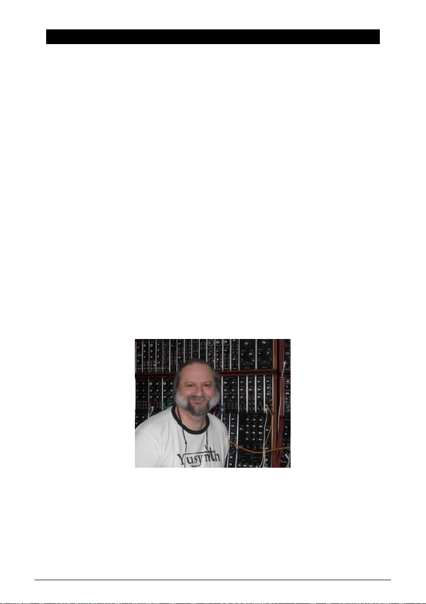
collaboration between Arturia's engineers and analog synthesizer "guru" Yves Usson.
Since the late 1990s, the French company Arturia has received acclaim from players
and reviewers alike for designing state-of-the art software emulations of the venerable
synthesizers from the 1960s to the 1980s. From the Modular V, back in 2004, to Origin, a
modular system they introduced in 2010; from Analog Factory Experience, the first hybrid
synthesizer ever (debuted in 2008), to the Synclavier V (2016) and the Buchla Easel V (2017),
their passion for synthesizers and sonic purity has given demanding musicians the best
software instruments for professional audio production.
After recreating so many legendary analog synthesizers by translating "golden" versions of
these classic instruments into sophisticated DSP algorithms, the time was right for Arturia
to introduce an analog synth of its own. But reproducing analog circuitry is not the same
as designing great-sounding analog circuits, so we enlisted the aid of Yves Usson — an
extremely talented analog circuit designer and synthesizer enthusiast whose work spans
three decades.
Besides being a talented researcher in bio-molecular microscopy, his clones of the modules
originally designed by Dr. Robert Moog, as well as ARP or EMS and his own designs,
are highly renowned in the "modular" world and continuously produced under license by
specialty manufacturers.
What’s more, he’s always willing to share his considerable experience and pass along his
knowledge to others. All his schematics stay open to the Synthesizer-Do-It-Yourself (SDIY)
community; most of his works can be found on the Yusynth ongoing project website, and
he casts a long, and welcome, shadow on the major Internet forums devoted to analog
fanatics.
Yves Usson and a couple of wired friends
Combining Arturia’s acclaimed
and Yves’ deep knowledge and experience, the MiniBrute 2S analog synthesizer has its roots
in the 1970s yet incorporates the best of the 21st century.
savoir-faire
in designing innovative musical instruments,
Arturia - User Manual MiniBrute 2S - Introduction 3
Page 10
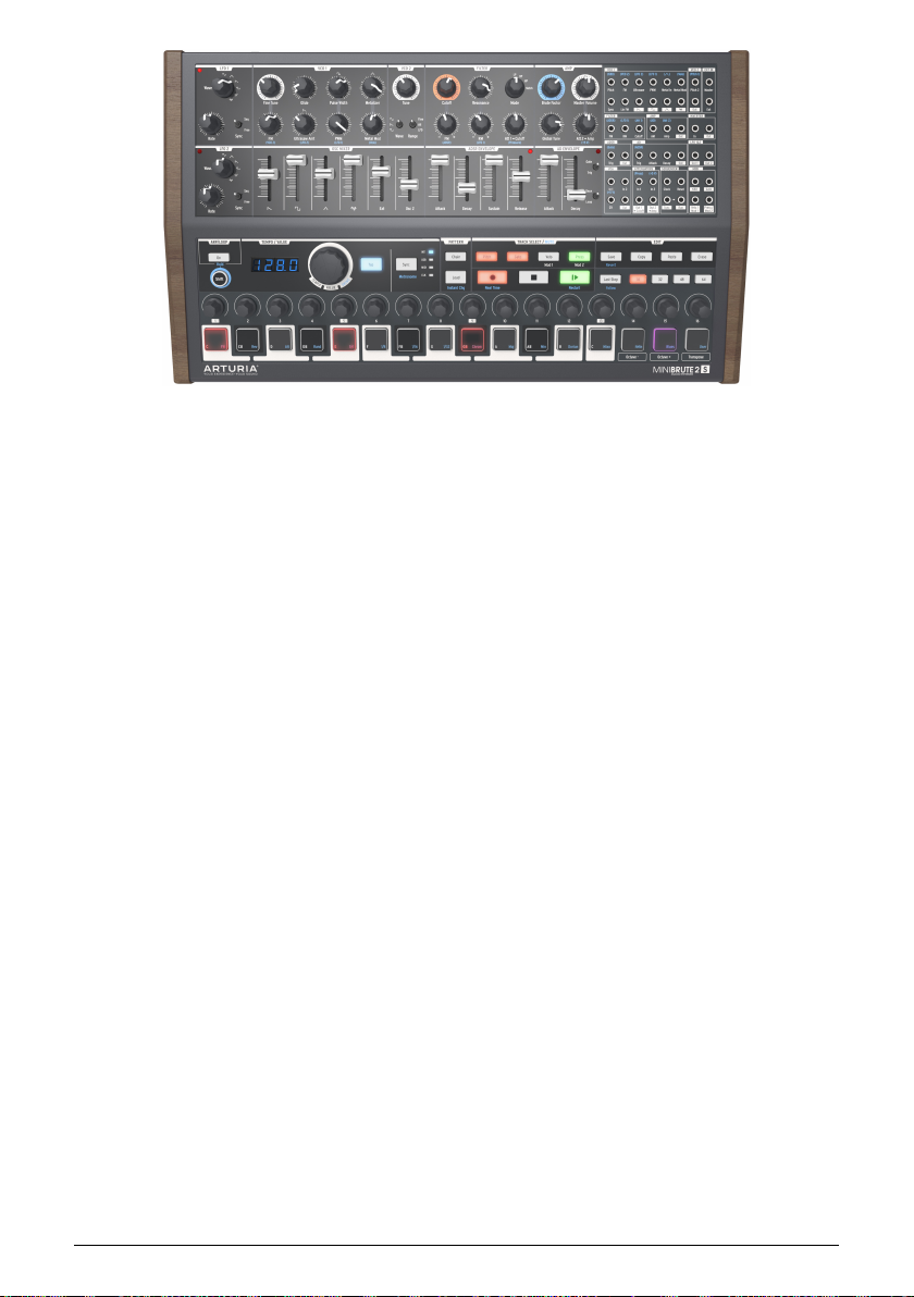
The Arturia MiniBrute 2S analog synthesizer
We built the MiniBrute 2S with four goals: peerless analog sound, intuitive operation,
affordability — and no compromises, whether with parts, design, or connectivity.
From the smallest capacitor to the potentiometers and the casing, we cherry-picked the very
best suppliers, subjected every component to exhaustive testing, and fine-tuned the design
for the best possible player experience.
Furthermore, we decided to bring back the fun of creating your own sounds, and controlling
them on stage or in the studio. There are no presets: All of the sound-shaping is at your
fingertips. This design philosophy also meant we could use true analog oscillators, not digital
ones, to provide the purity of sound that is the hallmark of analog synthesis.
But we also wanted you to be able to mangle that sonic purity the way the "big boys" can
(you know, those hulking modular synthesizers with patch cables running every which way).
So in addition to the powerful voice architecture the MiniBrute 2S provides a 48-point patch
bay, which allows you to bypass any pre-conceived notions regarding the signal path. Now
you can bring in control signals and audio from the outside world and patch them into the
MiniBrute 2S circuitry. This open-ended approach to sound design will open sonic doors you
never knew were there. We think it will even make the "big boys" come knocking at the door,
wanting to join the fun!
And yet for all its flexibility, the focus of MiniBrute 2S is on music, creativity, and the
experience of playing an instrument that is fun, physical, inspiring, and satisfying. What’s
more, with its compact size, MiniBrute 2S is ideal for the mobile and desktop musician. Not
only will it give you solid basses, amazing effects, and screaming lead lines, but it will give
you sounds no other synth on this planet can make.
As everyone knows, analog synthesizers are expensive to produce. But what’s the point in
making a synth for everyone, if no one could afford it? So, we made a bet it would be a hit,
and geared up to produce MiniBrute 2S in volume — allowing us to obtain quantity pricing on
parts, and translate the techniques of a craftsman to industrial manufacturing. The result is
analog synthesis without compromise.
MiniBrute 2S is truly a musical instrument. We loved designing it, building it, and now,
playing it. We hope you will share our enthusiasm, and find inspiration in its sounds.
Here’s an overview of the features at your disposal:
4 Arturia - User Manual MiniBrute 2S - Introduction
Page 11

• Fully analog signal path
• 2 multi-waveform voltage-controlled oscillators (VCOs)
• Sawtooth, square, and triangle waveforms (VCO 1)
• Ultrasaw, Metalizer, and pulse width modulation (PWM)
• Sawtooth, square, and sine waveforms (VCO 2)
• VCO 2 can be used as an additional LFO
• FM modulation between oscillators
• Random noise generator
• Steiner-Parker multimode filter with FM and RM (Resonance Modulation)
• 48-point patchbay
• Hard sync input for VCO1
• Separate VCA for modulation routings
• Two envelopes: ADSR (filter) and AD (amplitude)
• Loopable AD envelope
• Two multi-waveform LFOs with free-run or sync modes
• Brute Factor: overdrive the filter input with the audio output
• External audio can be routed through the Oscillator mixer or directly to the output
• Sequencer and arpeggiator, syncable to external clock: MIDI, USB, or CLK (1 step,
1 pulse, 24/48 ppq)
• MIDI input and output connectors
• USB port for use with a DAW
• Audio and headphone outputs
• Use with Arturia's MIDI Control Center for device configuration and sequence
archival
But that’s enough talk — plug in your new analog friend, and start shaking the walls!
Arturia - User Manual MiniBrute 2S - Introduction 5
Page 12

2. INSTALLATION
2.1. Usage Precautions
The MiniBrute 2S uses an external power adapter. Do not use any power supply or adapter
other than the one provided by Arturia. Arturia accepts no responsibility for damage caused
by use of an unauthorized power supply.
2.2. WARNING
Do not place this product in a place or position where one might walk on, trip over, or roll
anything over power cords or connecting cables.
The use of an extension cord is not recommended. However if you must use one, make sure
that the cord has the ability to handle the maximum current needed by this product. Please
consult a local electrician for more information on your power requirements.
This product should be used only with the components su pplied or recommended by Arturia.
When used with any components, please observe all safety markings and instructions that
accompany the accessory products.
2.3. Register your Instrument
Registering your instrument establishes your legal ownership, which entitles you to access
the Arturia Technical Support service, and be informed of updates.
Additionally, you can subscribe to the Arturia newsletter to be informed of Arturia-related
news as well as promotional offers.
Connect to your Arturia account via this URL:
https://www.arturia.com/login
Go to the section “
entering its serial number, as printed on the sticker located under the machine:
My Registered Products
”, and add the MiniBrute 2S synthesizer by
6 Arturia - User Manual MiniBrute 2S - Installation
Page 13

2.4. Connecting the MiniBrute 2S to the World
Always power-off all audio gear before making any audio connections. Failing to do so may
damage your speakers, the MiniBrute 2S synthesizer, or other audio equipment.
After completing all connections, set all levels to 0. Power on the various devices, with audio
amplifier or monitoring system
Here is an overview of the MiniBrute 2S synthesizer’s connectors:
Purpose Connector type
Audio output 6.35 mm (1/4'') mono jack (470 Ω impedance / line level)
Headphones
Patch bay (most jacks)
Patch bay (sync & clock
jacks)
MIDI input & output Standard MIDI DIN-5
USB Standard USB type B
Power DC input Internal 2.1 mm, external 5.5 mm
last,
then raise the volumes to a comfortable listening level.
6.35 mm (1/4'') TRS jack (signal is mono)
2Ω impedance (185mW @ 250Ω / 60mW @ 80Ω / 24mW @ 32Ω)
3.5 mm (1/8'') miniature mono jacks
CV in puts: Eurorack level signals, 100kΩ, +/-5Vx (Exception: Pitch CV inputs are
6.8MΩ impedance)
CV outputs: Eurorack level signals, 680Ω, +/-5V
Clocks / Gates inputs: Eurorack level signals, 68kΩ, 0V/+5V
Clocks / Gates outputs: Eurorack level signals, 2kR, 0V/+5V
3.5 mm (1/8'') miniature TRS jacks
Clock inputs: Eurorack level signals, 68kΩ, 0V/+5V
Clock outputs: Eurorack level signals, 2kR, 0V/+5V
Arturia - User Manual MiniBrute 2S - Installation 7
Page 14

2.4.1. The rear panel connectors
The MiniBrute 2S rear panel
2.4.2. Patch Bay
MiniBrute 2S patch bay, modular synth, and external audio sources
This is only one example of the connections that can be made between the MiniBrute 2S and
external devices. The possibilities are as endless as your imagination!
8 Arturia - User Manual MiniBrute 2S - Installation
Page 15

2.5. Warm-Up and General Tuning
As with all other true analog synthesizers, after being powered-on the MiniBrute 2S needs
a warm-up period of approximately five to ten minutes. This allows it to reach a stable
operating temperature, which ensures accurate oscillator pitch. Warm-up time depends on
the external temperature; a colder environment will require longer warm-up times, while a
hotter environment will result in shorter times. Humidity levels also can affect the length of
the warm-up period.
Once the synthesizer has reached its running temperature, tune it to pitch. Use an external
tuner to check the instrument’s tuning; if needed, adjust the Global Tune knob to tune the
MiniBrute 2S to the desired pitch.
The MiniBrute 2S has been designed for rock-solid pitch stability when operated in normal
temperature and humidity conditions, at external temperatures between 20°C and 32°C in
temperate areas. In practice, the MiniBrute 2S provides satisfactory operation over a much
wider temperature range, although extreme external temperatures or fluctuations can lead
to longer stabilization time or erratic tuning.
Arturia - User Manual MiniBrute 2S - Installation 9
Page 16
3. QUICK START
This chapter provides the basics you’ll need to create your very first sounds with the
MiniBrute 2S, so you can start enjoying its rich, full sounds immediately. In subsequent
chapters, we’ll get deeper into the sound design process so you can create more animated
and complex sounds.
This chapter also has introductory information about the Sequencer and the Arpeggiator
here [p.17].
3.1. Create your first sound: the “basic patch”
Once your MiniBrute 2S has been correctly connected to your sound system, set all the
controls to their minimum level: - counter-clockwise for the knobs - lowest position for sliders
- center position (12 o'clock) for controls with – and + (FM 1 and RM) - center position for all
three Tune controls - center position for the Master Volume knob
Switch on your MiniBrute 2S, and as you let it warm up [p.9], set the following parameters to
the recommended values:
• Set the LFO 1 and LFO 2 Sync switches to the Free position
• Set the LFO 1 and LFO 2 Rate controls to the center position
• Set the VCO 2 Wave [p.28] and Range [p.34] switches to their "up" positions (Sine
wave and Fine)
• Set the FILTER section’s Mode knob to LP
• Set the AD ENVELOPE switches to the Gate [p.44] and Once [p.44] positions
• Set the OSC MIXER section’s square wave slider to maximum
• Turn the FILTER section’s Cutoff knob fully clockwise
• Set the Sync setting to Int
♪: No cables should be connected to the patch bay yet.
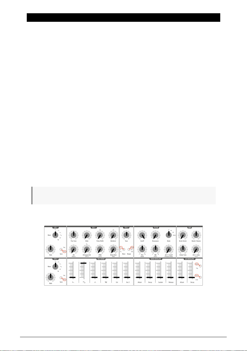
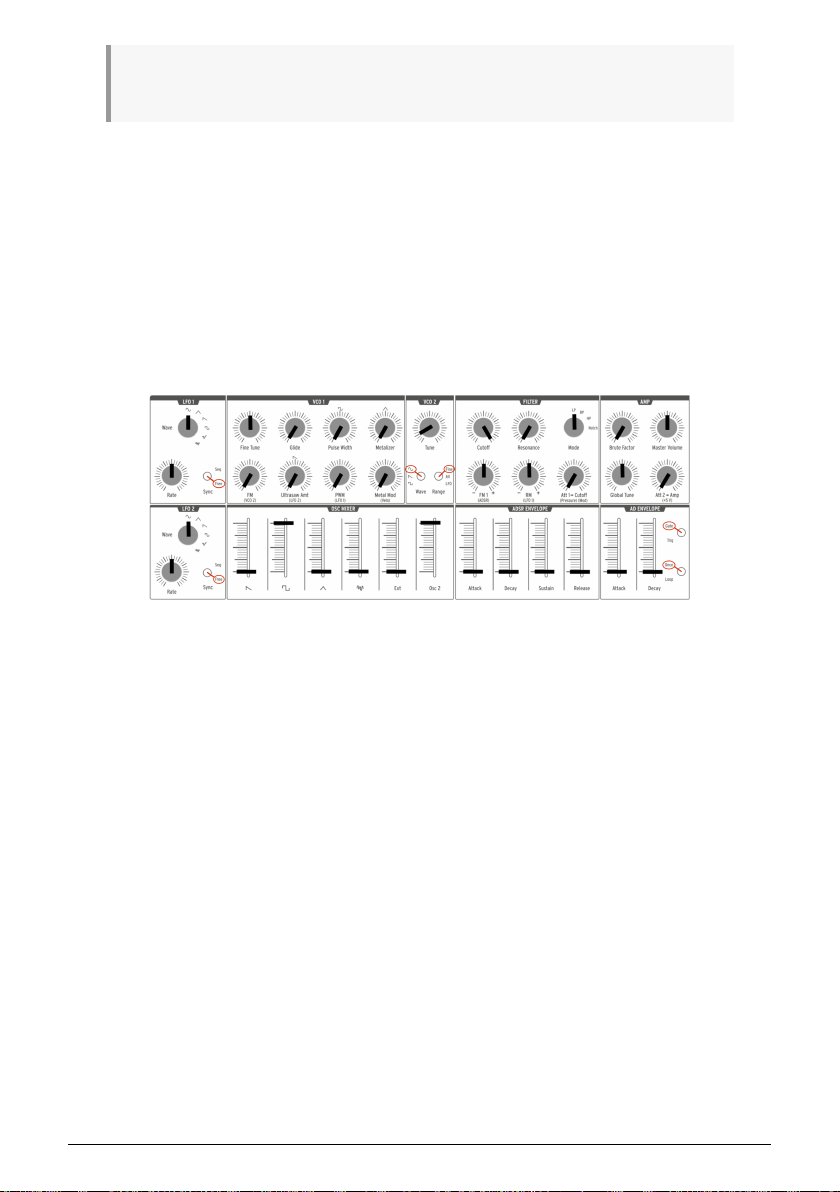
These settings give us a unified starting point for the following examples. Here’s a visual
representation of the patch:
The "basic" patch
Now, press a pad; you should hear your very first MiniBrute 2S sound!
That's a fat square wave... but it sounds a bit static, doesn't it? We’ll improve this in the Basics
of Synthesis [p.46] chapter. But if you simply want to play the pads for a moment, you can
use the Down or Up Octave [p.25] pads to transpose the notes to the range you prefer.
10 Arturia - User Manual MiniBrute 2S - Quick Start
Page 17
♪: Once the MiniBrute 2S has warmed u p, you can adjust the master tuning [p.9] as described in the
previous chapter.
3.2. Add a second oscillator
Press the Octave + pad to raise the pitch of the MiniBrute 2S by one octave. (The Octave +
pad is under knob #15.) Now press and hold a pad and do the following:
• Raise the Osc 2 slider in the OSC MIXER section to maximum
• Turn the VCO 2 Tune knob counter-clockwise until VCO 2 is an octave lower than
the original pitch.
• Play a few notes. VCO 2 has become a sub-oscillator, which beefs up your sound
by adding more bass.
Here’s an overview of the patch:
VCO 2 is being used as a sub-oscillator
Arturia - User Manual MiniBrute 2S - Quick Start 11
Page 18
3.3. Sweep the Filter with a pad
The obvious way to sweep the filter cutoff frequency is to grab the Cutoff knob and turn it.
But it's also very easy to use the pads to do the same thing while you're playing.
Leave all of the controls as they were in the sub-oscillator [p.11] example above, but make
these three changes:
• Set the Filter Cutoff knob to minimum
• Set the Att > Cutoff knob to maximum
• Switch VCO 2 to Sawtooth. Sawtooth waves have more harmonics, so the filter
sweep will be more obvious.
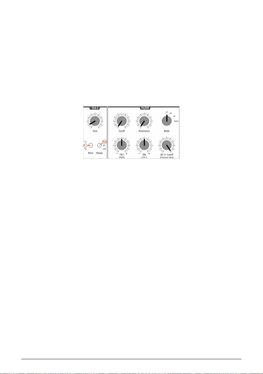
Here's how the parameters in the VCO 2 and Filter sections should look after those changes
have been made. The rest of the settings should still resemble the "sub-oscillator [p.11]" patch:
VCO 2 / Filter settings for the Filter Sweep
Now hold down a pad and slowly increase the pressure of your finger upon the pad. You'll
hear the filter open up as the pressure increases.
The pressure-sensitivity of the pads can be used to control other parameters, both inside the
MiniBrute 2S and on external devices. The patch bay [p.58] makes all of that possible.
example
12 Arturia - User Manual MiniBrute 2S - Quick Start
Page 19
3.4. Introduction to the LFOs
MiniBrute 2S has two independent low-frequency oscillators (LFOs) with identical
waveforms and controls. LFOs are used to "modulate" a parameter (i.e., change a
parameter) in a cyclical fashion. For example, an LFO can change the pitch of an oscillator
up and down gradually. That form of modulation is known as "vibrato."
In the following examples we'll use LFO 1, but the same experiments can be done with LFO
2. See the LFO section [p.28] of the Top Panel [p.28] chapter to learn more about the LFOs.
3.4.1. Sweep the filter with an LFO
An LFO can do much more than add vibrato [p.14] to the sound. For example, it can be used
to modulate the harmonic content. We will use the patch bay to illustrate this point.
• Set all sliders to minimum
• Set the square wave slider in the OSC MIXER section to maximum
• In the FILTER section, set the Cutoff and Resonance knobs to their middle points
(12:00)
• Set the FILTER section FM knob to the 12:00 position
• Also in the FILTER section, set the Mode knob to BP (band pass)
• Set the LFO1 Wave knob to Sine and its Rate to the 12:00 position
• Locate the LFO1&2 section in the patch bay
• Connect a patch cable to the Out 1 jack in the LFO1&2 section
• Locate the FILTER section in the patch bay
• Connect the other end of the patch cable to the Cutoff jack in the FILTER section
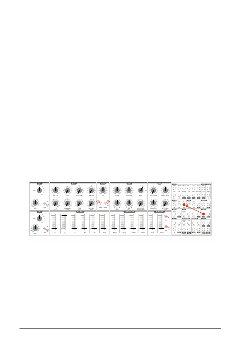
It's important that everything is set up properly, so here's how the patch should look:
LFO 1 modulating the filter cutoff via the patch bay
Play a pad. You should immediately hear timbre sweeps, a bit like a didgeridoo, at the
rate indicated by the red LED in the LFO 1 section. Tweak the Rate knob to slow down or
accelerate this wah-wah effect, and play with the filter's Resonance to accentuate it.
You also might want to try the various LFO waveforms, which we'll describe in the LFO
section [p.28] of the Top Panel [p.28] chapter.
We have barely scratched the surface! Thanks to the patch bay, an LFO can add a cyclical
variation to almost any aspect of the MiniBrute 2S sound. To learn more, read the Patch Bay
[p.58] chapter.
Arturia - User Manual MiniBrute 2S - Quick Start 13
Page 20

3.4.2. Add vibrato with VCO 2
There's a quick way to add vibrato without using the patch bay, and in the process we'll
learn a little more about VCO 2.
It's simple to set this up. Starting from the previous example [p.13]:
• Unplug the patch cable
• Switch VCO 2 Range to LFO
Now play a pad and slowly raise the VCO 1 FM knob — this will add some vibrato to the
sound.
Still holding the pad, turn the VCO 2 Tune knob clockwise to raise the LFO speed. You'll hear
the rate of the vibrato increase.
♪: The modulation happens without using patch cables because there is a pre-wired connection
between VCO 1 and VCO 2. This is what is meant by the blue letters under the VCO 1 FM knob that
say "VCO 2". To learn more about these pre-wired connections, see the first note (♪) in the VCO 1 [p.30]
section of the Top Panel [p.28] chapter. ♪: Since VCO2 tracks the pitch of VCO 1 by default, which in turn
tracks the transposition range of the pads by default, the LFO rate will increase or decrease as you
change the octave range of the pads. If you want the frequency of VCO 2 to be consistent across the
entire range of the pads, plug only one side of a patch cable into the Pitch 2 input jack in the patch bay.
See the Patch Bay [p.58] chapter to learn more.
14 Arturia - User Manual MiniBrute 2S - Quick Start
Page 21

3.5. Introduction to envelopes
MiniBrute 2S has two independent envelopes: the AD and the ADSR. The AD ENVELOPE
controls the amplitude of the sound, while the ADSR ENVELOPE is dedicated to the Filter; it
affects the harmonic content of the sound.
3.5.1. The AD envelope
The sound’s amplification envelope determines how the level changes over time when you
play a note. Up to this point in the chapter the note has only played while you were holding
a pad, which results in an “electronic organ” sound that has no dynamics. By changing the
AD ENVELOPE parameters (Attack, Decay) we can control how the sound fades in and fades
out.
Raise the AD ENVELOPE section’s Attack slider to its middle position, then press a pad. Now
the sound rises slowly to the maximum level. As soon as you release the pad, the sound
stops abruptly. Raise the Decay slider, and the sound will fade out to its minimum level when
you release the pad.
There are two switches inside the AD ENVELOPE section (Gate/Trig and Once/Loop [p.44]).
Their functions are somewhat more complex and will be described in the Top Panel [p.28]
chapter.
Arturia - User Manual MiniBrute 2S - Quick Start 15
Page 22
3.5.2. The ADSR envelope
This envelope controls the Filter, and it has more sliders than the AD envelope. The ADSR
envelope is slightly more complex to use, so we will describe the basic concepts here and
cover them more thoroughly in the Basics of Synthesis [p.55] chapter.
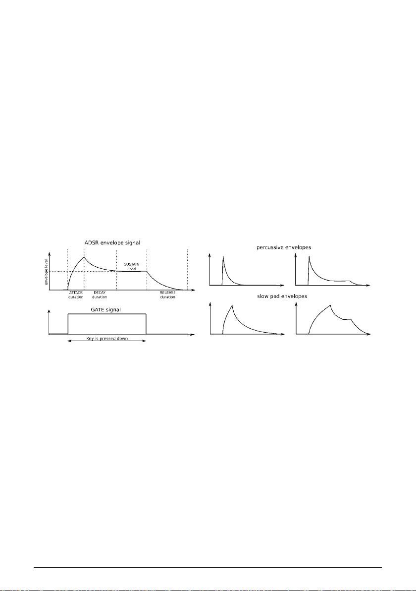
Pressing down a pad or sending a gate signal provides an evolving modulation signal with
up to four different stages:
• The attack stage determines how long it takes for the envelope to go from zero
to its maximum level. The attack time can be as short as 0.5ms or as long as 4
seconds.
• The decay stage begins when the attack stage reaches its maximum value, and
determines the time it takes to decrease from this maximum value down to a
steady level (set by the sustain parameter; see next). The speed of this decay can
vary from 0.5ms to 4 seconds.
• The sustain stage starts at the end of the decay phase, and remains at the
sustain value long as a pad is held down or a gate signal remains full on. The
sustain level is variable between zero (no sustain) and the envelope’s maximum
value.
• Finally, the release stage starts upon releasing the pad, and sets the amount of
time for the level to decrease from the sustain level down to zero. The release
time can be as quick as 0.5ms and as long 4 seconds.
Examples of the ADSR envelope
16 Arturia - User Manual MiniBrute 2S - Quick Start
Page 23
3.6. The Sequencer and Arpeggiator
As if you weren't having enough fun already, let's take a quick look at the Sequencer
and the Arpeggiator. To learn more about their features, we recommend starting with the
introductory chapter [p.83].
♪: Before you proceed, play a note to make sure you have sound. If not, raise the level on one of the
waveform sliders in the OSC MIXER section. If that doesn't help, you may want to revisit the Basic Patch
[p.10] section of the manual.
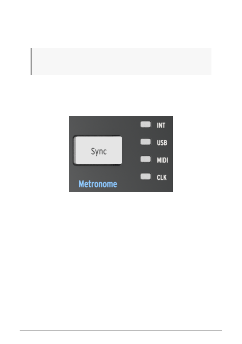
3.6.1. The Sync button
Before you can make music with the Sequencer or the Arpeggiator it is important to have
the Sync button set to Int (Internal). Look for a large button that says "Sync" (it's above knob
#7).
The Sync button
The four LEDs to the right of that button indicate the clock source for all of the timebased features of the MiniBrute 2S: the LFOs, the Sequencer, and the Arpeggiator. Push the
Sync button repeatedly until the LED next to the letters "INT" is lit. This means you have
selected the Internal clock and will be able to work with the Sequencer and the Arpeggiator
immediately.
Arturia - User Manual MiniBrute 2S - Quick Start 17
Page 24

3.6.2. The Arpeggiator
The MiniBrute 2S is in Sequencer mode by default. But you can switch to Arpeggiator mode
instantly by pressing the On button in the Arp/Loop section of the top panel. It looks like this:
The Arp/Loop section
Before you play the pads, let's configure the Arpeggiator so we'll be hearing the same thing.
So hold down the Shift button and then:
• Tap the "F" pad ("1/8")
• Tap the "G#" pad ("Chrom")
Now hold the Arp/Loop On button and turn the Tempo/Value knob until you see the word
"Up" in the display.
We'll explain what those settings mean in the Seq / Arp: shared features [p.83] chapter.
Now hold down at least 3 pads. You should hear those three notes repeated in order from
lowest to highest. If nothing happens, check the setting of the Sync button [p.17] again.
For a more lengthy explanation of what an Arpeggiator is, see the Arpeggiator Basics [p.125]
chapter. If you're curious about the more advanced Arp/Looper features, click here [p.134].
18 Arturia - User Manual MiniBrute 2S - Quick Start
Page 25

3.6.3. The Sequencer
The MiniBrute 2S allows you to record up to 64 patterns of your own. But there may be
something there already that you could use as a starting point later, so first we'll audition
the existing patterns. We'll learn how to record them [p.19] after that.
First, if the Arp/Loop button is lit, press it once and it will go dark. This means the Arpeggiator
is no longer active.
Next, hold down the Shift button and then:
• Tap the lowest "C" pad ("Fwd")
• Tap the "F" pad ("1/8")
• Tap the "G#" pad ("Chrom")
We'll explain what those settings mean in the Seq / Arp: shared features [p.83] chapter.
• Press the large Sync button until the INT LED is lit
• Hold the Load button (it's located above knobs 8 and 9).
While still holding the Load button, look at the pads. You will use them to select the pattern
you want to load. Some of the pads may be lit, which means they already contain pattern
data. The flashing pad indicates which pattern has already been loaded into memory.
• Select a pad that is lit
• Press the Play button.
The sequence you selected will begin to play. If you do not hear anything, set up the Basic
Patch [p.10] again.
To select another pattern, hold the Load button and press a different pad.
3.6.3.1. Record a pattern (real time)
♪: For a brief example of step-mode recording, click here [p.21].
If you've found an empty pattern, or at least a pattern you don't want to keep, let's make a
quick real-time recording.
• Enable the metronome by holding the Shift button and then pressing the Sync
button. If the Sync button lights up when you press the Shift button, the
metronome is already enabled.
• Hold the Record button
• Press the Play button
As soon as you press Play, the Record button will become blue, the metronome will start,
and the sequencer will begin recording.
♪: When the Record button is blue, the MiniBrute 2S is in real-time recording mode. When the Record
button is red, the MiniBrute 2S is in step-time recording mode.
Now play the pads as if you were playing a piano keyboard. The default length of a pattern
is 1 bar (16 steps), so the sequencer will loop around after that and you'll hear the notes you
played.
Arturia - User Manual MiniBrute 2S - Quick Start 19
Page 26

You can exit Record mode by pressing the Record button again. To disable the metronome,
hold the Shift button and press the Sync button until it goes dark.
!: If you've created a pattern you'd like to keep, hold the Save button and press the pad that is
flashing. Do this before you load another pattern or you will lose your new pattern. You may want to
read the Save a pattern [p.105] section to learn how to copy a pattern to a new location, etc.
Each MiniBrute 2S pattern has four parallel tracks. In addition to note data, many other types
of control data may be recorded there.
For a more lengthy introduction to the Sequencer, see the Sequencer Basics [p.99] chapter.
If you're ready to learn how to change the length of a pattern, edit individual note data, and
record information into the other parallel tracks, see the Sequence Editing [p.108] chapter.
20 Arturia - User Manual MiniBrute 2S - Quick Start
Page 27

3.6.3.2. Record a pattern (step mode)
♪: For a brief example of real-time recording, click here [p.19].
If you've found an empty pattern, or at least a pattern you don't want to keep, let's make a
quick recording in Step mode.
• Enable the metronome by holding the Shift button and then pressing the Sync
button. If the Sync button lights up when you press the Shift button, the
metronome is already enabled.
• Press the Record button, and then release it
• Press the Play button
As soon as you press Play the metronome will start and the sequencer will begin recording.
But unlike real-time record mode, the Record button is red to signify step recording mode.
♪: When the Record button is red, the MiniBrute 2S is in step-time recording mode. When the Record
button is blue, the MiniBrute 2S is in real-time recording mode.
When you're ready, press a pad and it will turn red to enable that step in the sequence.
Press the pad again to disable that step and it will go dark.
The default length of a pattern is 1 bar (16 steps), so the sequencer will loop around after
that and you'll hear the steps you enabled.
But if you started with an empty pattern, all the notes will play back at the same pitch. This
is because the pitch of each step is actually entered using the knobs above the pads.
To test this, turn the knob above one of the lit pads by one click. You'll see the TEMPO/VALUE
display change from the tempo to a note name like "C#3" or "B 2". Notes can be changed
using this method whether the sequencer is running or not, as long as the unit is in Record
mode (i.e., the Record button is lit).
You can exit Record mode by pressing the Record button again. To disable the metronome,
hold the Shift button and press the Sync button until it goes dark.
!: If you've created a pattern you'd like to keep, hold the Save button and press the pad that is
flashing. Do this before you load another pattern or you will lose your new pattern. You may want to
read the Save a pattern [p.105] section to learn how to copy a pattern to a new location, etc.
For a more lengthy introduction to the Sequencer, see the Sequencer Basics [p.99] chapter.
If you're ready to learn how to change the length of a pattern, edit individual note data, and
record information into the other parallel tracks, see the Sequence Editing [p.108] chapter.
Arturia - User Manual MiniBrute 2S - Quick Start 21
Page 28

4. HARDWARE OVERVIEW
4.1. Main features
The MiniBrute 2S takes a multi-layered step sequencer, an arpeggiator, a powerful analog
monosynth, and a flexible patch bay, and combines them into a powerful music creation
station. As its initial interface it provides a set of drum-machine-style pads, arranged in a
piano-style layout and spanning a single octave. Besides offering a way to play notes, the
pads provide additional ways to express your musical ideas:
• Pressure generates a signal that corresponds to how hard you press a pad after
it has been played. You can use this signal to modulate vibrato, filter cutoff, and
other parameters.
• Velocity corresponds to the dynamics of your playing, and similar to aftertouch,
can modulate multiple parameters.
• Transposition allows shifting the note range of the pads over six octaves.
• An arpeggiator automates the creation of repeating sequences of notes.
• The sequencer allows you to trigger musical passages you have created, such
as melodies, bass lines, or percussive riffs.
Alternative ways of playing the synthesizer are available through USB/MIDI control and
external CV/GATE signals.
4.2. The Shift button
The Shift button is circled in blue to draw attention to the blue letters that are silkscreened in
various areas of the Sequencer section. For example, look under the Tempo knob, under the
buttons, and inside the pads: you'll see blue words and numbers.
When the Shift button is held and the corresponding button or pad is pressed, secondary
functions are activated or toggled. For example, the Step Size of a pattern can be changed
to 1/16th notes by holding the Shift button and pressing the F# pad.
For a complete description of the secondary Shift features, see the Shift functions [p.158]
chapter.
♪: The Shift button is not related to the blue letters silkscreened under the synthesizer knobs or inside
the patch bay.
22 Arturia - User Manual MiniBrute 2S - Hardware overview
Page 29
4.3. Inputs and outputs
In order to hear the MiniBrute 2S, its audio output needs to connect to an audio amplifier
either directly or through a mixer console (or use the Headphones output).
As to control, the MiniBrute 2S can accept control voltage signals from devices like a modular
synthesizer or a MIDI controller (e.g., a MIDI drum pad or wind controller), or even audio
signals from an external sound source such as a microphone or electric guitar.
The means to control other instruments, or be controlled by other instruments, is provided
by the collection of inputs and outputs such as USB/MIDI in and out, an external audio input,
and the input and output connectors on the patch bay.
♪: It is necessary to use a pre-amplifier to raise the level of an audio source to match the line-level
inputs of the Ext In section in the patch bay.
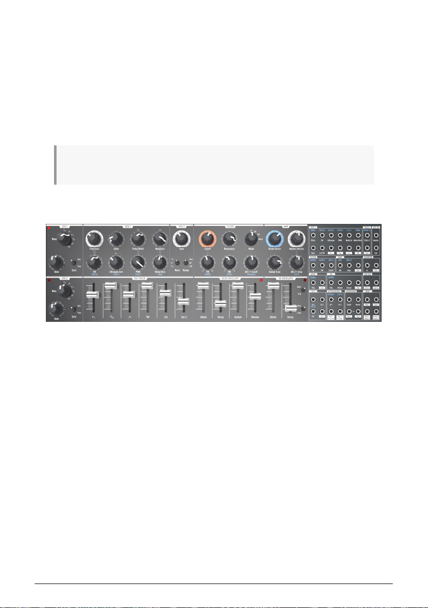
4.4. Top panel
The top panel of the MiniBrute 2S
This is where all of the synthesizing takes place. There are so many powerful features
located here that the top panel [p.28] has its own chapter. The Patch bay [p.8] has its own
chapter too.
Arturia - User Manual MiniBrute 2S - Hardware overview 23
Page 30
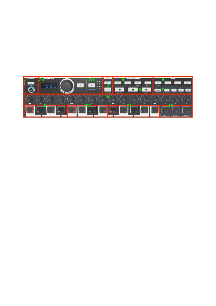
4.5. The Sequencer section
This is where all of the music-writing happens: the capturing of ideas, their refinement,
and the spontaneous improvisation that takes your music to places you had previously left
unexplored.
Each of the zones in this section plays an important part in what will become a creative
liberation for you. These controls serve all of the basic functions you would expect of a
sequencer in a modular system, and as you work with them you will come to love the
simplicity and sensibility of the workflow.
But the more you work with them, the more you will be amazed how the
these controls unlock features you never knew you needed.
The Sequencer section of the MiniBrute 2S
Here's a quick description of each section. For the full details, see these chapters: Seq / Arp:
shared features [p.83], Sequencer Basics [p.99], and Sequence Editing [p.108].
1. Arp/Loop (Hold): enable/disable the Arpeggiator; use Shift to hold the arpeggio
and access blue-letter secondary functions
2. a: The Tempo/Value knob will adjust tempo, access banks, select functions,
set swing values, etc. The Tap button helps set the tempo. The tempo value
is displayed to the left of the Tempo knob. b: The Sync button selects the
clock source for time-based functions (Seq/Arp/LFOs); Shift + Sync enables the
metronome.
3. Pattern Chain / Load (Instant Change): Load patterns and chain them together;
Shift + Load toggles instant vs. delayed pattern loading
4. Track Select (Mute): Access the four sequence tracks; use with Shift to mute
tracks
5. Transport buttons (Real Time, Restart): Standard controls (Rec/Stop/Play/Pause);
Shift toggles Real-time vs. Step record, Restart Seq/Arp
6. Edit (Recall): Pattern management; Save/Copy/Paste/Erase; use Shift to recall a
stored pattern
7. Last Step / Pages 16-64: define the length of a pattern and access the step pages
of longer patterns. Use Shift + Last Step to follow song pointer; Use Shift + Page
button to extend pattern to the corresponding page
8. Step encoders 1-16 (Secondary functions): edit step data within a pattern
9. Pads C – D# (Seq/Arp direction): play notes; Shift + pad sets the pattern direction
10. Pads E – G (Seq/Arp step size): play notes; Shift + pad sets timing resolution of
the pattern
11. Pads G# – C (Preset scales): play notes; Shift + pad selects certain preset scales
12. Octave/Transpose (Preset/User scales): Octave shift; Transpose + pad to
transpose pattern; Shift + pad selects other preset scales and User scale
combinations
of
24 Arturia - User Manual MiniBrute 2S - Hardware overview
Page 31

4.5.1. The Octave & Transpose pads
♪: When you change the octave range or transposition with the [Octave -/+] pads, the change will
happen only after a pad has been pressed.
4.5.1.1. Octave + / - pads
The Octave pads can transpose the MiniBrute 2S pads and sequences over a wide pitch
range.
• Pad range: Press [Octave -] once to shift the pads down by one octave. Press
[Octave -] a second and third time to access lower notes. The pad will flash to
indicate that the octave range has been shifted, and flash more quickly as the
range is moves further from center.
To shift the pads up by an octave press the [Octave +] button. The pads can be shifted
upward three times, and will flash more quickly as the range moves further from center.
♪: To shift the pad range back to center immediately, press both pads at the same time.
• Patterns: Here's how to shift the octave range of a pattern:
♪: The octave shift amount is stored with each pattern.
1. Press Play to start the pattern
2. Hold the Transpose pad and then...
3. Press the [Octave -] pad to shift the pattern downward by octaves, or
4. Press the [Octave +] pad to shift the pattern upward by octaves.
5. To shift the pattern range back to center immediately, hold Transpose
and press the [Octave -/+] pads at the same time.
Arturia - User Manual MiniBrute 2S - Hardware overview 25
Page 32

4.5.1.2. Transpose a pattern
Here's how to transpose a pattern while it is playing back:
1. Press Play to start the pattern
2. Hold the Transpose pad
3. Press the pad with the note name that corresponds to the desired transposition
amount. For example, pressing the D# pad while the Transpose pad is held will
shift the pattern up by a minor third.
4. To put the pattern back to the original pitch, hold Transpose and press the lowest
C pad.
5. If you have changed the Octave range by holding the Transpose button and
pressing the Octave -/+ pads, you will need to use those pads as well to restore
the pattern to its original pitch.
♪: Transposing a pattern does not transpose the pads; it only transposes the pattern. The pads will
remain at their original pitches.
26 Arturia - User Manual MiniBrute 2S - Hardware overview
Page 33

4.6. The rear panel
There are several types of connectors on the rear panel. When viewed left to right:
4.6.1. Kensington lock
The small hole over the product name is a security feature called a Kensington lock. We want to be sure that your creativity takes flight only when you want it to.
4.6.2. Outputs
Connect headphones to the headphone jack for personal monitoring and connect a 1/4" TS
(tip-sleeve) cable to the Master jack to run the audio into a mixer or external amplifier.
4.6.3. MIDI
Connect a pair of the classic 5-pin DIN cables to the MIDI In and Out ports to interface with
other MIDI devices. Clock, control, and note data can be sent and received. The reception of
MIDI clock signals is dependent on the Sync [p.87] setting.
4.6.4. USB
Connect a standard type-B USB cable to the USB port to interface with a computer. Clock,
control, and note data can be sent and received. The reception of USB/MIDI clock signals is
dependent on the Sync [p.87] setting.
In addition, the USB port is used to connect the MiniBrute 2S to Arturia's MIDI Control Center.
This software is used to configure various settings of the MiniBrute 2S.
♪: Synchronization with non-MIDI devices is done through a connector on the patch bay. For a full
description of the CLK setting and the connector types to use, see the Synchronization [p.87] section.
4.6.5. Power
Connect only the included power adapter to this jack. It will supply the necessary voltage
and current to power the analog circuitry of the MiniBrute 2S: 12V DC (center pin positive)
and 2A (for Amperes).
Arturia - User Manual MiniBrute 2S - Hardware overview 27
Page 34

5. THE TOP PANEL
This chapter covers the synthesizer features of the MiniBrute 2S: the oscillators, the filter,
the envelopes, etc. Click the following links for descriptions of the patch bay [p.58], the
Sequencer [p.19] and Arpeggiator [p.18], and the Sync [p.87] settings.
5.1. The LFOs
An LFO is low frequency oscillator that can produce various waveforms at sub-audio
frequencies (0.0625Hz up to 100Hz). The MiniBrute 2S provides two LFOs, each with
waveform choices of sine, triangle, sawtooth, square, two types of random waves.
Each LFO has its own Wave selector, Rate control, a switch that determines whether it will
run freely or synchronize to the master clock.
The LFO 1 section
♪: LFO 1 and 2 are identical, so this section of the manual applies equally to both.
5.1.1. Wave
The LFOs offer several types of modulation waveforms. The selection is made by the Wave knob: sine, triangle, sawtooth, square, random stepped (also referred to as Sample & Hold), and random gliding (or smoothed random).
• Sine rises and falls smoothly between its minimum and maximum values
• Triangle rises and falls in more of a linear manner between its minimum and
maximum values
• Sawtooth falls to its minimum value in a linear manner and then rises suddenly
to its maximum value
• Square rises and falls suddenly between its minimum and maximum values
• Random stepped rises and falls suddenly between values that are generated at
random
• Random gliding rises and falls gradually between values that are generated at
random
28 Arturia - User Manual MiniBrute 2S - The top panel
Page 35

The sampling rate of the Random waveforms is controlled by the Rate knob, the same way the rate
of the other LFO waveforms is controlled (see below).
5.1.2. Sync
The Sync switch sets the LFO rate’s operating mode. It can be slaved to the Sequencer/
Arpeggiator tempo clock (Seq) or set to Free mode (i.e., the LFO rate depends solely on the
Rate knob setting).
5.1.3. Rate
The Rate knob sets the LFO oscillation rate, and ranges from very slow rates (once every 16 seconds, or 0.0625Hz) up to quite fast rates (100Hz). The red LED located near the knob blinks in time with the rate. Note that the LFO rate may be superseded by the Sequencer/ Arpeggiator tempo clock if the Sync switch is set to Seq (see above).
When set to Sync the LFO rate will always be a multiple or a subdivision of the Seq/Arp
tempo. As the LFO Rate knob is turned clockwise:
• Each increase in the LFO rate doubles the LFO frequency
• Each decrease in the LFO rate cuts the LFO frequency in half.
There are nine potential rates when an LFO is set to Sync:
Rate LFO cycle repeats every: Periodicity
1 8 bars 8x
2 4 bars 4x
3 2 bars 2x
4 1 bar 1x
5 half note 0.5x
6 quarter note 0.25x
7 eighth note 0.125x
8 sixteenth note 0.0625x
9 thirty-second note 0.03125x
Arturia - User Manual MiniBrute 2S - The top panel 29
Page 36

5.2. VCO 1
The VCO 1 section has eight controls that form the foundation of the MiniBrute 2S sound.
The VCO 1 section
♪: Many top panel knobs have blue letters beneath them. This means there are pre-wired connections
between those knobs and the blue-lettered item. For example, (VCO 2) is written beneath the FM knob.
That means the second voltage-controlled oscillator (VCO 2) is the default source for the modulation
that happens when the FM knob is turned clockwise. Similarly, LFO 2 is the default modulation source
for Ultrasaw Amt. Keep this in mind as you look around the top panel for other pre-wired connections.
5.2.1. Fine Tune
This knob allows you to make precise adjustments to the pitch of VCO 1. Its range is slightly
greater than one octave in either direction. Rotate the knob counter-clockwise to lower the
pitch, and rotate the knob clockwise to raise the pitch.
♪: Changing the Fine Tune knob of VCO 1 does not affect the pitch of VCO 2.
5.2.2. Glide
Glide is also known as Portamento. The Glide knob determines the amount of time it takes
for the pitch to glide from one note to another when notes are played. With this knob fully
counter-clockwise, there is no glide and the note pitch transitions instantly to the next note.
Turning this knob clockwise increases the portamento effect. At the maximum setting it will
take 3 seconds to glide from the first note to the second note, regardless of the distance
between them.
♪: By default the pitch of VCO 2 will track the pitch of VCO 1 when the Glide value is increased. The
main exception to this rule is when a patch cord is inserted into the Pitch 2 input [p.68] jack in the VCO
2 section of the patch bay [p.58].
30 Arturia - User Manual MiniBrute 2S - The top panel
Page 37

5.2.3. Pulse Width
This knob affects only the square wave of VCO 1. It has no impact on the saw or triangle
waveforms. What it does is alter the width of the square wave from a "round-sounding" 50%
to increasingly narrow-sounding pulse waves. See the Signal enhancers [p.48] section of the
Basic Synthesis [p.46] chapter for a visual representation of the waveforms.
The Pulse Width can be modulated by an LFO or other sources via the patch bay. See the
PWM [p.31] section for more information and related links to other chapters.
♪: The setting of the Pulse Width knob does not affect the square wave of VCO 2.
5.2.4. Metalizer
This knob affects only the triangle wave of VCO 1. It has no impact on the saw or square waveforms. The Metalizer takes the peaks of the basic triangular waveform and “folds” them downward to create very complex jagged waveforms that are rich in high harmonics. See the Signal enhancers [p.48] section of the Basic Synthesis [p.46] chapter for a visual representation of the waveforms.
5.2.5. FM
FM stands for Frequency Modulation. This knob affects all three waveforms of VCO 1 at
the same time. By default the FM source is VCO 2, so the frequency of that oscillator will
modulate the frequency (pitch) of VCO 1 as the value of this knob is increased.
When range switch of VCO 2 is set to LFO the frequency modulation will sound more like
vibrato. But when it is set to Fine or All the frequencies of VCO 2 are so high that they will
cause a significant disru ption to the waveforms being generated by VCO 1. The resultant
sound can be clangorous (bell-like) or somewhat noisy depending on the frequencies and
waveforms involved.
5.2.6. Ultrasaw Amt
This knob affects only the sawtooth wave of VCO 1. It has no impact on the square or
triangle waveforms. An increase in its value will mix the original sawtooth wave with
two phase-shifted copies of itself, resulting in a fatter sound. The result is different in
character than that of detuned sawtooth waveforms being generated by two different VCOs.
See the Signal enhancers [p.48] section of the Basic Synthesis [p.46] chapter for a visual
representation of the waveforms.
5.2.7. PWM
The Pulse Width of the square wave can be modulated by a source such as LFO 1 (the prewired default) or another source via the patch bay [p.58]. See the Signal enhancers [p.48]
section of the Basic Synthesis [p.46] chapter for a visual representation of the waveforms.
♪: This knob affects only the square wave of VCO 1. It has no impact on the saw or triangle
waveforms of VCO 1 nor the square wave of VCO 2.
Arturia - User Manual MiniBrute 2S - The top panel 31
Page 38

5.2.8. Metal Mod
The Metal Mod knob sets the modulation range for the Metalizer knob. Velocity is routed to
the Metal Mod by default, but the patch bay allows you to use something else to modulate
the parameter instead.
32 Arturia - User Manual MiniBrute 2S - The top panel
Page 39

5.3. VCO 2
MiniBrute 2S has two oscillators that are completely independent: each has its own
waveshape and tuning, and can be mixed separately in the OSC MIXER section. They share
the filter and amplifier stages.
The VCO 2 section
There is a certain level of pre-wired interaction between VCO 1 and VCO 2, though. For
example:
• The pitch of VCO 2 will track that of VCO 1 by default, but there is an input on the
patch bay that allows the VCO 2 pitch to track another source.
• The pitch of VCO 1 can be modulated by the pitch of VCO 2 through the FM knob
in the VCO 1 section. (FM is an abbreviation for Frequency Modulation.) But there
is an in put on the patch bay that allows the VCO 1 pitch to be modulated by
another source.
The output level of the second oscillator is controlled with the slider labeled Osc 2. Pulling it
down reduces the level of the signal and moving it up increases its level.
The VCO 2 section contains a Tune knob and two toggle switches:
5.3.1. Tune
The Tune knob sweeps VCO 2 through the range determined by the Range switch (see below). Generally the middle position will tune it to the same pitch as VCO 1, but some adjustment may be necessary until the oscillators have warmed up.
5.3.2. Wave
The Wave switch selects the waveshape for VCO 2, which can be either a sine wave, a
sawtooth wave, or a square wave.
Arturia - User Manual MiniBrute 2S - The top panel 33
Page 40

5.3.3. Range
The Range switch sets VCO 2 to one of three tuning ranges:
• Fine: a full turn of the knob covers a range of more than an octave above and
below the center frequency
• All: a full turn of the knob will sweep VCO2 through the entire frequency range
of the MiniBrute 2S
• LFO: VCO2 can be used as an additional LFO with a wide frequency range (1Hz
to audio range). This is handy if you're already using LFOs 1 and 2 for other
modulations through the patch bay, for example.
34 Arturia - User Manual MiniBrute 2S - The top panel
Page 41

5.4. The Filter section
The filter alters the oscillators’ timbre via the four response modes described in the next
chapter [p.50] (LP, BP, HP & Notch). Its cutoff and resonance can be adjusted manually.
The cutoff can also be controlled by the keyboard and modulated by various modulation
generators. The MiniBrute 2S filter is based on Nyle Steiner’s
(designed in the 70s) and offers -12dB/octave slopes in LP and HP modes, and -6dB/octave
slopes in BP and Notch modes.
The Filter section
5.4.1. Mode
Sallen & Key
architecture
This selects among the four filter modes: LP (low-pass), BP (band-pass), HP *
and *
Notch. The LP mode is the most commonly used, and provides sounds which are full,
fat, and round. The BP and HP modes provide thinner and harsher sounds. When modulated
by an LFO, the Notch filter mode sounds similar to a phaser effect pedal.
(high-pass),
5.4.2. Cutoff
This knob adjusts the filter’s cutoff frequency. The frequency range goes from below 20Hz
when turned fully counter-clockwise up to 18kHz when fully clockwise. For example, in LP
mode you can adjust a sound’s brightness. As an exercise,
• Set all of the OSC MIXER sliders to 0 (lowest position)
• Adjust the NOISE generator slider to midrange
• Set all of the filter envelope and amplifier envelope sliders to 0
• Set the filter mode to LP
• Play and hold a note
• Adjust the Cutoff knob as you listen to the changes in the sound.
♪: You may want to try the same experiment with the other filter settings (BP, HP, and Notch). Since
a noise source contains all frequencies, this is a great way to hear exactly which ones are cut and
boosted by each filter type. !: Resonant filters can overload an audio circuit very easily. Be careful with
the various levels involved (Noise level, Resonance amount, Master Volume, and the channel settings of
your mixer or speaker). This is especially true when you are working with headphones!
Arturia - User Manual MiniBrute 2S - The top panel 35
Page 42

5.4.3. Resonance
This knob lets you create a resonance peak at the cutoff frequency. Turning it clockwise
emphasizes the partials at the cutoff frequency, and the sound becomes more aggressive.
When the knob reaches its last quarter zone, the filter starts to oscillate on its own. However,
this oscillating behavior depends on the cutoff frequency; the MiniBrute 2S filter oscillates
within a range beginning around 180Hz up to approximately 8kHz. To extend the oscillation
range, use the Brute Factor knob.
5.4.4. FM knob
The FM knob lets you control the amplitude and polarity of the envelope signal sent
to modulate the filter cutoff frequency. At the middle position (12 o'clock), no envelope
modulation occurs. When turned counter-clockwise (below the center), the FM knob sends
an increasing amount of the inverted ADSR envelope. When turned clockwise (above the
center) the FM knob sends an increasing amount of the standard, positive-going ADSR
envelope.
♪: If you do not hear the effect of a negative-going filter envelope, try raising the Cutoff frequency.
Conversely, if you do not hear the effect of a positive-going filter envelope, try lowering the Cutoff
frequency.
5.4.4.1. ADSR (the filter envelope)
The letters "ADSR" are silkscreened under the FM knob because this connection has been
pre-wired for you. However this connection can be bypassed through the patch bay [p.58].
The ADSR Envelope [p.55] is covered extensively in the Basics of Synthesis [p.46] chapter.
36 Arturia - User Manual MiniBrute 2S - The top panel
Page 43

5.4.5. RM (Resonance Modulation)
This parameter modulates the level of resonance that will occur at the cutoff frequency of
the filter. It is pre-wired to be modulated by LFO 2, but the patch bay can be used to route
another input as the resonance modulation source.
This control is bi-polar, which means it allows the modulation to be either positive- or
negative-going. It also means that when the knob is set to the center position (12:00) no
modulation will occur.
Here's a good experiment to illustrate what the RM parameter does:
• Set all of the OSC MIXER sliders to 0 (lowest position)
• Adjust the NOISE generator slider to midrange
• Set all of the filter envelope and amplifier envelope sliders to 0
• Set the filter mode to LP
• Set the Cutoff knob to the 10:00 position
• Set the Resonance knob to the middle position (12:00)
• Set the LFO 1 waveshape to Sawtooth and the Rate to the 10:00 position
• Play and hold a note
• Slowly turn the RM knob clockwise (positive). At about the 3:00 position you
should hear a falling "chirp" similar to an early electronic drum kit.
• Slowly turn the RM knob counter-clockwise (negative). At about the 9:00 position
you should hear that same "chirp" sound, but it will rise instead of fall. It will
actually sound like a recording of the same drum is being played backward.
Here's a graphic representation of the RM experiment:
Experimenting with RM modulation
♪: For the technically-minded, you may notice that there is a slight deformation of the RM signal due
to the threshold in the bipolar attenuator circuitry.
Arturia - User Manual MiniBrute 2S - The top panel 37
Page 44

5.4.6. Att 1 > Cutoff
This parameter provides another method of modulating the filter cutoff frequency. It is prewired to control the amount of pressure-sensitivity that will be applied to the filter, but the
patch bay can be used to route another input as the modulation source.
The "Att 1" portion of the label stands for "Attenuator 1". The patch bay has a section labeled
"Attenuators", and when a different source is routed to the first pair of connectors there, that
input source becomes the modulator for which the Att 1 > Cutoff knob sets the modulation
range. There's more to say about using the patch bay and the Attenuators [p.76], and we'll
cover that in the patch bay chapter [p.58].
38 Arturia - User Manual MiniBrute 2S - The top panel
Page 45

5.5. The Amplifier section (AMP)
The amplifier section controls the final stage of the MiniBrute 2S output. Everything else that
has happened on the synth will be fed through this section before it reaches the audio output
connectors.
The Amplifier section
5.5.1. Brute Factor
The Brute Factor is a special MiniBrute 2S feature inspired by a common patch used on
a famous vintage mono-synthesizer that connected the headphone output to the external
audio input. The result is a kind of feedback loop that’s ideal for raspy and grungy sounds.
This patch has been implemented internally to the MiniBrute 2S, and is controlled by the
Brute Factor knob.
This knob’s normal position is fully counter-clockwise, which disables the Brute Factor; turning up the knob gradually adds distortion to the sound. For low * the distortion is smooth and gentle, but it becomes more harsh as you turn up the knob. When turned u p higher than about 75% of the way, the MiniBrute 2S can go berserk and produce barely controllable, crazy feedback sounds.
Brute Factor *
settings
!: The Brute Factor feature drastically alters the filter characteristics, so expect highly unpredictable
results at extreme settings. You have been warned!
5.5.2. Master Volume
This knob controls the overall output level of the MiniBrute 2S, and also controls the audio
that arrives at the Master input in the patch bay. It affects only the rear panel outputs
(Master and Headphones).
5.5.3. Global Tune
Once the oscillators have warmed up you can use this knob to tune the MiniBrute 2S to other
devices. See the Warm-Up and General Tuning [p.9] section of the Installation chapter [p.6]
for more information.
Arturia - User Manual MiniBrute 2S - The top panel 39
Page 46

5.5.4. Att 2 > Amp
Under ordinary circumstances the Att 2 > Amp knob is kept at the minimum position; this
allows the AD Envelope generator to open and close completely from silence to silence.
However, there may be times when a non-zero setting of this knob is very useful. For
example:
• To keep the amplitude at a constant level so you can program a sound with both
hands
• To create a drone patch that is constantly evolving as parameters are being
modulated via the patch bay
• To create a patch with an infinite decay/release time
The beauty of having a knob to control this parameter, rather than a switch that simply
forces the VCA to a never-ending maximum level, is that you can control the level at which
the envelope stays open.
40 Arturia - User Manual MiniBrute 2S - The top panel
Page 47

5.6. The Osc Mixer
The oscillators deliver four basic waveforms: sawtooth, pulse, triangle, and sine (VCO 2
only). These waveforms are accessible through the Oscillator mixer and their respective
levels can be adjusted with the sliders. A second oscillator is available to thicken the sound
through detuning or setting its pitch to other intervals.
The mixer also controls the level of noise and of external audio (if an external source
is plugged into the patch bay's Ext in jack). The mixed signals then feed the filter. The
waveforms of VCO 1 can also be modified using signal enhancers (Ultrasaw, Pulse Width
Modulation and Metalizer).
The Oscillator mixer section
5.6.1. Saw / Ultrasaw (VCO 1)
The combined level of the plain Saw (sawtooth) and Ultrasaw signals is controlled with the
slider labeled with the saw icon. Pulling it down completely mutes the signals, while moving
it up increases their level. When the Ultrasaw Amt knob is fully counter-clockwise, only the
saw signal is audible. Turning this knob clockwise mixes more Ultrasaw sound in with the
plain saw signal.
The Ultrasaw consists of two copies of the plain saw that are independently phase-shifted
using LFO 2 (by default). The phase shift of one copy is modulated at a constant rate
(1Hz), while the second copy’s phase shift modulation rate can be controlled with the LFO
2 Rate knob from a rate of 0.1Hz (minimum) for slow-beating frequency effects, increased
gradually for chorusing and supersaw effects, and increased further to 100Hz (maximum)
for special effect sounds.
The shape of the phase-shifting can also be altered by changing the LFO 2 waveform.
5.6.2. Square / Modulated Pulse (VCO 1)
The level of the plain Square wave and Pulse width modulated signals is controlled with
the slider labeled with the square symbol. Pulling it down completely mutes the signals
and moving it up increases their level. When the PWM knob and the Pulse Width knob are
both fully counter-clockwise, the pure square wave is audible. Turning the Pulse Width knob
clockwise transforms the square wave into an asymmetrical pulse whose width can be
increased up to 98%, giving a very “acid” sound (like an oboe).
The pulse width is also under the control of LFO 1 by default. The depth of the pulse width
modulation can be adjusted with the PWM knob in the VCO 1 section, and the shape of the
LFO can be changed the with LFO 1 Wave knob.
Arturia - User Manual MiniBrute 2S - The top panel 41
Page 48

5.6.3. Triangle / Metalizer (VCO 1)
The level of the Triangle wave and Metalizer is controlled with the slider labeled with the
triangle icon. Pulling it down completely mutes the signals and moving it up increases their
level. Turning the Metalizer knob from fully counter-clockwise to fully clockwise warps the
triangle wave’s smooth, flute-like sound into complex, metallic-sounding waves.
The wave warping/folding is also under the control of an additional modulator: the Metal
Mod knob. Velocity is routed to the Metal Mod by default, but the patch bay allows you to
use something else to modulate the parameter instead.
♪: The Metalizer knob sets the minimum amount of waveshaping and the Metal Amt knob sets the
modulation range for additional waveshaping. But they share the same amount of warping/folding
potential, so if the Metalizer knob is at maximum there is very little headroom left for modulation by the
Metal Amt source.
5.6.4. Noise
The signal mixer also provides the control of other signals which aren’t generated by the
oscillators. The Noise slider potentiometer adjusts the amount of white noise signal sent to
the filter. Mixing a small amount of noise with oscillator waves creates a kind of breathing,
natural quality. For example, mixing the Triangle wave with a small quantity of noise creates
a credible flute sound. Noise is also useful on its own to create various special effects or
nature sounds such as wind, water streams, and rain, as well as percussive sounds such as
cymbals.
5.6.5. Ext
The Ext slider adjusts the amount of an external audio source that can be plugged into the
MiniBrute 2 signal path via the Ext jack in the EXT IN section of the patch bay [p.58]. This
makes it possible to process an external audio signal with the filter and amplifier.
5.6.6. Osc 2 (VCO 2)
This slider controls the output level of VCO 2 into the Amplifier section. See the VCO 2 [p.33]
section for a full description of the capabilities of the second oscillator,
42 Arturia - User Manual MiniBrute 2S - The top panel
Page 49

5.6.7. ADSR Envelope sliders
These four sliders affect the Filter by default. Their functions are described extensively in the
Basics of Synthesis chapter [p.55].
The ADSR Envelope section
♪: An LED indicator shows the envelope amount that is being sent to the filter. The LED’s brightness
depends on the envelope signal’s amplitude.
5.6.8. AD Envelope sliders
These two sliders affect the Amplifier by default. Their functions have been described
extensively here [p.15], but here's a quick review:
• The Attack slider sets the duration of the envelope’s first stage. The Attack time
ranges from 1ms to 14s.
• The Decay slider sets the duration of the AD envelope’s final stage. The Decay
time ranges from 1ms to 14s.
The AD Envelope section
♪: An LED indicator shows the envelope amount that is being sent to the amplifier. The LED’s
brightness depends on the envelope signal’s amplitude.
Arturia - User Manual MiniBrute 2S - The top panel 43
Page 50

5.6.9. AD Envelope switches
Normally the amplifier envelope is triggered by the playing of a note, but it can also be
triggered by other sources via the patch bay. Whichever method is used to trigger the
envelope, the four switches in the AD Envelope section determine the behavior of the
envelope after it has been triggered.
5.6.9.1. Gate/Trig
This switch toggles the function of the AD Envelope between two settings: Gate and Trig.
• Gate: The AD Envelope starts when a note is played/triggered and proceeds to
maximum level at the Attack rate. The amplifier sustains at maximum level until
the note is released, and then the envelope enters the Decay stage. The envelope
will not reset completely to zero if another note is triggered before the Decay
stage has ended; it will resume the attack stage of the amplitude envelope and
proceed to maximum level at the Attack rate.
• Trig: The AD Envelope starts when a note is played/triggered. There is no sustain
stage; the envelope enters the Decay stage after the Attack time has been
fulfilled. The full envelope will run unless another note is triggered, at which time
the amplitude resets to zero and the envelope starts again.
♪: The AD Envelope is normally triggered when the ADSR Envelope is triggered, but a different trigger
source may be routed into the AD Envelope via the patch bay.
5.6.9.2. Once/Loop
This switch toggles the function of the AD Envelope between two settings: Once and Loop.
• Once: When a note is played/triggered the amplitude rises from zero at the
Attack rate and returns to zero at the Decay rate.
• Loop: When the envelope reaches the end of the Decay stage it will start over
from the beginning. It will continue to loop through the Attack and Decay stages
until the note is released or retriggered.
The following chart may be helpful in keeping track of what happens when different
combinations of these two switches are used.
Switch
combination
Gate + Once
Gate + Loop
Trig + Once
Trig + Loop
AD Envelope response
The envelope rises when it receives a gate signal (note on). It falls when the gate ends (note
off).
The envelope rises when it receives a gate signal (note on), and loops until the gate ends (note
off), at which point it falls from its current position.
The envelope plays an Attack-Decay cycle when it receives a trigger (note on). The envelope
is retriggered when it receives a new trigger, regardless of the current position.
The envelope loops indefinitely and is retriggered by a new trigger (note on), regardless of the
current position.
44 Arturia - User Manual MiniBrute 2S - The top panel
Page 51

5.7. The Patch bay section
For a description of the patch bay features, see the Patch Bay chapter [p.58].
5.8. Secondary Shift functions
There are some very useful secondary functions that are activated by holding the Shift
button and then pressing a pad or a button. For a description of those features, see the Shift
functions [p.158] chapter.
Arturia - User Manual MiniBrute 2S - The top panel 45
Page 52

6. BASICS OF SYNTHESIS
Your MiniBrute 2S is a true analog synthesizer, so all sounds are produced by analog
electronic circuits. No digital computer circuitry is involved in the generation, filtering, or
basic control of the sound. This is one of the reasons why MiniBrute 2S creates rich,
animated, and lively electronic sounds.
6.1. Analog synthesizer architecture
The analog sound production chain uses a classical approach called subtractive synthesis.
The basic sound generator is a waveform with a rich harmonic content; filtering then
“subtracts” harmonics to create new variations on the original timbre. Subsequent circuits
(an envelope generator in conjunction with a VCA, or voltage-controller amplifier) alter the
level in a precise way to create dynamics.
6.1.1. Signal generators
The signal generators are the circuits that produce the basic waveforms for sound creation.
There are two basic categories: pitched signal generators and the unpitched signal
generators.
6.1.1.1. Pitched signal generator (oscillators)
This device, also called an oscillator, produces an electronic signal characterized by a
repetitive, shaped pattern (called a waveform). The number of times this pattern re peats
in a second determines the signal’s frequency, which determines its pitch. For example, a
pattern that repeats every 2.27ms corresponds to a fundamental frequency of 440 cycles
per second, or 440 Hertz (a unit of measurement for cycles per second named in honor of
Heinrich Hertz, who first demonstrated the existence of magnetic waves, and abbreviated
Hz). This frequency is associated with the pitch of middle A on a piano keyboard. In general,
oscillators will provide some or all of the following basic waveforms: sine wave, triangular
wave, sawtooth wave, square and pulse waves.
A single cycle of each waveform: sine, triangle, sawtooth, square, and
If these waveforms have the same frequency, then their pitch is equivalent. However,
different waveform shapes have different timbres. For example, the sine wave sounds dark
and plain, while the sawtooth wave sounds very bright. The square wave sounds a bit like a
clarinet and the pulse wave resembles an oboe.
These complex waveforms are actually made up of multiple sine waves — a fundamental
sine wave that determines the base frequency, and sine waves representing higher
harmonics (also called overtones or partials) of that frequency which, when added together,
produce a unique timbre. These harmonics are an integer multiple of the fundamental
frequency, i.e., the second harmonic is twice the fundamental frequency, the third harmonic
is three times the fundamental, and so on.
pulse
46 Arturia - User Manual MiniBrute 2S - Basics of synthesis
Page 53

The fundamental frequencies and harmonics of sine and sawtooth
waveforms
Most importantly, other devices can control an oscillator to set its pitch (keyboard controller),
modulate its pitch (vibrato), and modulate the shape of the waveforms (PWM, Ultrasaw).
6.1.1.2. Unpitched signal generator
Unlike the previous category, an unpitched signal generator (also called noise generator)
has no regular, periodic pattern — the signal’s amplitude is always changing randomly.
Therefore, it has no fundamental frequency (hence no pitch), and its harmonic spectrum
consists of a nearly infinite number of frequencies that have no harmonic relationship.
The output of a random noise generator
Such signals sound very different from the pitched signals, and are like the sound of wind,
a water stream, steam exhaust, rain, waterfall, etc.
Arturia - User Manual MiniBrute 2S - Basics of synthesis 47
Page 54

6.1.2. Signal enhancers
Signal enhancers (or wave-shapers) transform or distort the oscillator’s basic pitched signal
to increase their harmonic content, and make them sound brighter and richer. The MiniBrute
2S provides three signal enhancers:
• The Ultrasaw builds two phase-shifted copies of the basic sawtooth signal. These
copies have independent and ever-evolving phase shifts with respect to each
other, and are eventually mixed with the sawtooth signal. This results in a lively,
rich, and bright ensemble effect whose character depends on the modulation
rates of the phase-shifted copies.
The generation of an Ultrasaw waveform
• The Pulse Width Modulator (or PWM) takes the square wave and changes the
ratio between the time the waveform is at maximum or minimum. The square
wave corresponds to a 50% PW. The pulse width can be set over a wide range
(50% to 90%) making it possible to create a wide variety of instruments that
sound "reedy", or like woodwinds.
The pulse width of a square wave can be modulated
• The Metalizer takes the basic triangular waveform and “warps/folds” it to create
very complex jagged waveforms that are rich in high harmonics. This results in
“metallic” pitched sounds that are ideal for harpsichord- and clavinet-type tones.
Dynamic modulation (LFO or envelope) of the warp/folding parameters opens
up a realm of clangorous, spring coil-like sounds.
48 Arturia - User Manual MiniBrute 2S - Basics of synthesis
Page 55

The top of a triangle wave is folded over by the Metalizer
Arturia - User Manual MiniBrute 2S - Basics of synthesis 49
Page 56

6.1.3. Filter
6.1.3.1. What is a filter?
In general, a filter follows the signal generator and signal enhancers, and modifies the
spectral content of the signal or signals. This can involve either attenuating (filtering out) or
emphasizing (resonating) particular overtones and partials, and these changes can be either
static or dynamic. Filters are very important circuits whose design contributes greatly to the
a synthesizer’s sound and character.
50 Arturia - User Manual MiniBrute 2S - Basics of synthesis
Page 57

6.1.3.2. Filter types: Low-pass, Band-pass, High-pass and Notch
A filter can operate in various ways or modes. These modes are called transfer functions
or spectral responses. In the MiniBrute 2S the filter can operate either as a low-pass filter, a
band-pass filter, a high-pass filter, or a notch filter.
In low-pass mode, the spectral contents below a given
cutoff) remain unchanged, while partials above the cutoff are attenuated. The attenuation
is a function of the frequency where the higher the partial frequency, the greater the
attenuation. In other words, it is called a low-pass mode because it passes the low
frequencies below the cutoff and reduces the high frequencies above the cutoff. This
correlation of attenuation to frequency determines the filter’s slope, which is measured in
-dB/octave (i.e., the amount of attenuation applied to a partial with a frequency twice as
high as the cutoff).
cutoff frequency
(shortened to
How a low-pass filter affects the sound
In band-pass mode, the cutoff frequency becomes a band’s center frequency. Partials
within this band remain unchanged, while partials below or above the band’s range are
attenuated strongly.
How a band-pass filter affects the sound
In high-pass mode, partials above the cutoff frequency remain unchanged, while the
partials below the cutoff are attenuated.
How a high-pass filter affects the sound
Arturia - User Manual MiniBrute 2S - Basics of synthesis 51
Page 58

In notch mode (or rejection filter) the cutoff frequency becomes a band’s center frequency;
partials within this band are attenuated, while partials above and below this band remain
unchanged.
How a notch filter affects the sound
The cutoff frequency doesn’t have to be static; controlling it with other devices like a
keyboard (keyboard tracking), or LFO, envelope generator, or other controllers, creates
dynamically-changing, interesting timbres.
6.1.3.3. Resonance or emphasis
Resonance is a filter’s ability to amplify or emphasize partials that are close to the cutoff
frequency, thus creating a peak in the spectral response. This parameter can be increased
up to a point where the filters no longer acts like a mere filter, but starts to oscillate on its
own.
The resonance emphasizes a particular range of frequencies
52 Arturia - User Manual MiniBrute 2S - Basics of synthesis
Page 59

6.1.4. Amplifier
The amplifier generally follows the filter, and determines the signal’s overall amplitude. Its
gain is controllable through various modulation sources such as an LFO, envelope generator,
or some kind of external control (like a foot pedal). The amplifier is primarily responsible for
shaping a sound’s dynamics.
The Amplifier is the final stage of the signal
Arturia - User Manual MiniBrute 2S - Basics of synthesis 53
Page 60

6.1.5. Modulators
Modulators provide signals that are designed specifically to control the behavior of
oscillators, filters and amplifiers. Unlike audio oscillators, modulators are low-frequency
signals. For example, when you sing with vibrato, you are “modulating” your voice with a
low-frequency change in pitch, typically around 5Hz or so. The tremolo circuit in a guitar
amplifier modulates the amplifier’s level.
Modulators are useful to create dynamic pitch changes (like “wobulation” or creating chirps),
timbre sweeps, and level variations. The main modulators are the LFO (low frequency
oscillator) and envelope generator, but they can also be provided by external sources that
generate
modulators or notes on and off.
An LFO is low frequency oscillator that can produce various waveforms at sub-audio
frequencies (0.05Hz up to 100Hz). In MiniBrute 2S the waveform options are sine, triangle,
sawtooth, square, random steps, and random waves. These waves’ amount and polarity
(i.e., whether they go positive or negative) can be controlled before being fed to the target
devices.
control voltage
(CV) signals that provide modulation, and
gate
signals that turn
6.1.5.1. Low-Frequency Oscillators (LFOs)
A signal can be modified by random steps or smoothed random steps
54 Arturia - User Manual MiniBrute 2S - Basics of synthesis
Page 61

6.1.5.2. Envelope generators
Contrary to an LFO, an envelope generator does not provide a repeating pattern but is
controlled by the keyboard or Gate input. The AD ENVELOPE controls the amplitude of the
sound, while the ADSR ENVELOPE is dedicated to the Filter and affects the harmonic content
of the sound.
♪: The patchbay allows the envelopes to be routed to other destinations and triggered by other
sources.
AD (Attack, Decay)
The AD envelope determines how the level changes over time when you play a note. By
changing its parameters (Attack and Decay) we can control how the sound fades in and
fades out. We experimented with the AD envelope [p.15] in the Quick start chapter.
ADSR (Attack, Decay, Sustain, Release)
The Attack, Decay, Sustain, and Release sliders control different stages of the Filter envelope.
Here's a quick walk-through of each stage.
• Set the AD ENVELOPE Attack and Decay sliders to minimum
• Turn the FILTER Cutoff knob to minimum
• In the OSC MIXER section,
The sawtooth wave has more harmonic content than the square wave, which will make it
easier to hear the impact each of the ADSR stages has on the filter.
◦ Lower the Osc 2 slider to minimum
◦ Lower the Osc 1 square wave slider to minimum
◦ Raise the Osc 1 sawtooth slider to maximum
Attack
Play a note. The sound will be very faint.
• Turn the FILTER section's FM1 knob clockwise to maximum
• Raise the ADSR Attack slider until it is 3/4 of the way up
Now play a note and hold it. The harmonic content of the sound will increase gradually until
the sound is very bright, and then it will fall off very quickly because the Decay slider is set
to minimum.
Decay
• Lower the ADSR Attack slider to minimum
• Play a note repeatedly and raise the ADSR Decay slider gradually until it is 3/4
of the way up
Now play a note and hold it. The sound will start quickly and be very bright, but the harmonic
content will be reduced gradually until the sound is very faint again. The decay time of the
filter envelope makes a major contribution to the character of a sound.
Arturia - User Manual MiniBrute 2S - Basics of synthesis 55
Page 62

Sustain
The Sustain stage controls a level, not a rate. It sets the target for the Decay stage, the
resting point for the decay of the harmonic content.
• Set the ADSR Decay slider to the halfway point
• Play a note and listen to resting point of the harmonic content
• Raise the ADSR Sustain slider to about 2/3 of the way up
Now play a note and hold it. The harmonic content of the sound will decay as quickly as
it did when the first note was played, but it will not decay the same amount this time. The
Sustain level tells the filter that it should remain somewhat open as long as the note is held.
This allows a certain amount of harmonic content to remain audible.
Release
Until this point in our ADSR experiments the filter envelope has always cut off quickly after
the note has been released. The Release stage controls the amount of time it will take for
the filter to die out after releasing the note.
• Raise the AD Decay slider to about 3/4 of the way up
• Set the ADSR Decay and Sustain sliders to about 2/3 of the way up
Play the same note repeatedly and raise the ADSR Release slider gradually. The harmonic
content of the notes you play will take longer to die out after the notes are released.
But this part may be more difficult to understand unless we also perform the following
experiment.
• Lower the AD Decay slider to minimum
• Play a note and release it. The sound will die out as soon as the note is released.
Now play the same note repeatedly as you raise and lower the ADSR Release slider. The
slider doesn't seem to be doing anything now. This is because the AD envelope controls the
amplitude of the sound; if the amplitude has been reduced to zero by the AD Decay stage
upon the release of the note, the ADSR Release stage will not be heard because the sound
itself is no longer audible.
56 Arturia - User Manual MiniBrute 2S - Basics of synthesis
Page 63

6.1.5.3. AD Attack vs. ADSR Attack: What's the difference?
Now that we've gone through all of the stages of each envelope type, let's do a quick
experiment to illustrate the difference between them.
• In the FILTER section, set the Cutoff knob to minimum and the FM1 knob to
maximum (+)
• In the OSC MIXER section, set the sawtooth slider to maximum and all other
sliders to minimum
• Set all sliders to minimum in the ADSR and AD Envelope sections as a starting
point
• In the ADSR ENVELOPE section, raise the Decay and Sustain sliders to the
halfway point
• No cables should be connected in the patch bay.
Here's an overview of the patch at this point, just to make sure we're on the same page:
Starting point for ADSR/filter envelope example
When you play a note the sound should start quickly and brightly and die just as quickly
when the note is released. While the note is being held its harmonic content should take
about 2 seconds to reach the Sustain level.
• Raise the ADSR Attack slider to the halfway point
• Play a note and hold it. The harmonic content of the sound will build gradually.
• Lower the ADSR Attack slider to minimum again.
• Raise the AD Attack slider to about 3/4 of the way up
Now play a note and hold it while listening carefully. The sound will fade in gradually but its
harmonic content will remain constant throughout the change in amplitude.
Arturia - User Manual MiniBrute 2S - Basics of synthesis 57
Page 64

7. THE PATCH BAY
The MiniBrute 2S is an impressive synthesizer with a powerful set of analog circuitry that
puts it in a class of its own. But with the addition of the patch bay the MiniBrute 2S joins
ranks with modular synthesizers many times its size.
The MiniBrute 2S patch bay
This manual will focus mostly on the individual sections of the MiniBrute 2S patch bay and
how they relate to one another. But there are as many additional ways to use the patch bay
as there are external synthesizers that can generate compatible signals.
7.1. General concepts
7.1.1. Patch bay sections
A white line is drawn around certain grou pings of in put/output jacks. This indicates which
connections are related to which MiniBrute 2S components.
White lines mark section boundaries in the patch bay
In the example above, the first three jacks on the left pertain to the Filter, the three in the
middle pertain to the final output stage (AMP), and the two jacks on the route signals to/
from the Inverter circuit.
We'll cover the function of each section of the patch bay later in this chapter.
58 Arturia - User Manual MiniBrute 2S - The Patch bay
Page 65

7.1.2. Patch points: Inputs vs. Outputs
The connectors in the MiniBrute 2S patch bay fall into two main categories: inputs and
outputs. It is easy to know which is which: The output jacks are labeled with white boxes
containing text or graphics, and the input jacks only have words under them.
The input and output jacks have different
Use the output jacks as sources for the input jacks, and use the in put jacks as destinations
for the output jacks.
label types
7.1.3. Outputs are full-scale
The signal at the output jacks is the direct output of whatever source they represent. For
example, the waveform output jacks in the VCO 1 section are full-strength; adjusting the
sliders in the OSC MIXER section will not control their output levels.
Direct waveform outputs
Other examples include the Out 1 and Out 2 jacks in the LFO 1&2 section. If the direct output
signal of an LFO is too wide for the desired input destination, it will need to be limited
somehow. Fortunately, we have provided two sets of Attenuators in the patch bay for this
purpose. We'll describe how to use the Attenuators [p.76] in that section of the manual.
Arturia - User Manual MiniBrute 2S - The Patch bay 59
Page 66

7.1.4. Pre-wired connections
Many of the patch points have blue letters silkscreened above the jacks. If you look closely,
you will notice that these are all input jacks.
Blue labels show default input routings
We'll go over what each one of these labels means as we cover each section of the patch
bay. But to use one example from the section pictured above, the label (KBD) means the
Pitch of VCO 1 normally tracks the MiniBrute 2S pads (abbreviated KBD). If a patch cable
is connected to the VCO 1 Pitch jack it will break this connection and tell VCO 1 to expect
its modulation signals to come from another source such as an LFO or the output of an
envelope.
60 Arturia - User Manual MiniBrute 2S - The Patch bay
Page 67

7.1.5. External devices vs. internal routings
Most of the input and output jacks can be connected to others within the patch bay. However,
some of the connectors make the most sense in terms of connection to an external device.
For example, consider the Sequencer section:
The Sequencer section of
the patch bay
The Clock in put jack is intended to receive signals from an external device so that the
MiniBrute 2S Sequencer and Arpeggiator can be synchronized to an external clock source.
Likewise, the Sync output jack is intended to transmit signals to an external device so that
the MiniBrute 2S can serve as the master clock source for an external device.
♪: The MIDI Control Center software allows you to specify what sort of clock the MiniBrute 2S should
send and receive. A wide range of options is available; see the MCC [p.140] chapter for more information.
7.1.5.1. Control voltage inputs
Some labels reveal the default control voltages the MiniBrute 2S is using internally:
Arturia - User Manual MiniBrute 2S - The Patch bay 61
Page 68

These labels indicate internal voltages
For example, for the VCA section's CV in put and the ATTENUATOR section's Att 2 in put, the
pre-wired control is the internal +5V source of the MiniBrute 2. But you can patch any control
voltage standard into the patch bay here (1V, 2V, 5V, 8V, etc.).
62 Arturia - User Manual MiniBrute 2S - The Patch bay
Page 69

7.2. The VCO 1 section
The VCO 1 section
7.2.1. Pitch
The pre-wired connection into the Pitch of VCO 1 is the pads (KBD). Plugging in a patch cable
will break that connection and allow the new source to control the VCO 1 frequency.
7.2.2. FM
When a patch cable is connected to the FM input jack the pre-wired connection between
VCO 1 and VCO 2 is broken. As with VCO 2, the amount of the VCO 1 frequency modulation
(FM) is governed by the FM knob in the VCO 1 section of the top panel. That knob must be
set to a value higher than zero for FM to occur.
7.2.3. Ultrasaw
Normally the intensity of the Ultrasaw [p.41] waveform modifier is based on the settings of
LFO 2. Interrupting that connection with a patch cable allows the new source to control the
phase shift modulation rate of the second copy of the sawtooth wave.
Remember: the amount of the Ultrasaw modulation is governed by the Ultrasaw Amt knob
in the VCO 1 section of the top panel. That knob must be set to a value higher than zero for
the Ultrasaw to be heard. The Sawtooth slider in the OSC MIXER section must also be set
high enough for the basic sawtooth wave to be heard.
7.2.4. PWM
LFO 1 is the source of the Pulse Width Modulation (PWM) by default, but another source can
be used to control it through this patch point.
To hear PWM it is necessary to have the PWM knob in the VCO 1 section of the top panel set
to a non-zero value. The Square wave slider in the OSC MIXER section must also be set high
enough.
Arturia - User Manual MiniBrute 2S - The Patch bay 63
Page 70

7.2.5. Metal In
The Metal In patch point allows an incoming source to be wave-folded the same way the
VCO 1 triangle wave would be. Inserting a patch cable here bypasses the pre-wired VCO 1
triangle waveform.
To hear the Metalizer effect on the source it is necessary to have the Metalizer knob or the
Metal Mod knob set to a non-zero value. The Triangle wave slider in the OSC MIXER section
must also be set high enough.
Remember: the Metalizer and Metal Mod knobs affect one another: a combination of the
Metal Mod source and the setting of the Metal Mod knob interact to alter the level of the
Metalizer effect.
The Metal In jack is AC-coupled, which is a technical term that means that slow LFOs or envelopes
are not likely to be wavefolded properly by the Metal In circuitry. We recommend the use of audio
signals such as oscillators as an input for this jack.
7.2.6. Metal Mod
The default source of the Metal Mod parameter is the velocity of a note played on the
MiniBrute 2S pads. But a different source may be used by connecting its output to this patch
point.
For example, try connecting a patch cable from the Out 1 of the LFO 1&2 section of the
patch bay to the Metal Mod input. The depth of the LFO 1 modulation of the Metalizer can be
adjusted with the Metal Mod knob, while the LFO 1 rate and waveform can be used to shape
that modulation in different ways.
Remember: the Metalizer knob sets the initial amount of the Metalizer effect, and the Metal
Mod knob determines how much modulation of that amount will occur.
64 Arturia - User Manual MiniBrute 2S - The Patch bay
Page 71

7.2.7. Sync
There is no pre-wired connection for this input. It can be used to set up the classic "hard
sync" sound by forcing VCO 1 to follow the pitch of VCO 2.
Here's an example patch:
• Tune VCO 2 down one octave
• Set VCO 2 Wave to Square and Range to Fine
• Transpose the MiniBrute 2S down two octaves
• Set all OSC MIXER faders to minimum except Sawtooth
• In the VCO 1 section, set Fine Tune and FM to about the 3:00 position
• Select LP in the Filter section and set FM and RM to center (12:00)
• Set Cutoff and Resonance to zero and Att 1>Cutoff to 2:00
• Set the ADSR Attack and Release to zero
• Set the ADSR Decay and Sustain about 2/3 of the way up
• Make the following connections in the patch bay:
Here's roughly how the patch should look. We've omitted the LFOs and other irrelevant
settings:
◦ MIDI section: KBD (Out) to VCO 2 section: Pitch 2 (In)
◦ VCO 2 section: Out to VCO 1 section: Sync (In)
◦ ADSR section: Out to ATTENUATORS section: In 1
◦ ATTENUATORS section: Out 1 to VCO 1 section: Pitch (In)
Hard Sync example patch
Now play some low notes. You should hear a recognizable sync sweep.
Arturia - User Manual MiniBrute 2S - The Patch bay 65
Page 72

7.2.8. Lin FM
Linear (Lin) FM will add harmonics to VCO 1 in a very different way than the exponential FM
provided by the FM knob in the VCO 1 section. One of the characteristics of Linear FM is that
it is less likely to disrupt the fundamental pitch than Exponential FM.
Here's an experiment that may help show the difference. First, reconstruct the basic Square
Wave patch [p.10] from the Quick Start chapter and then:
• Raise the level of Osc 2 in the OSC MIXER
• Set the VCO 2 Range to All and tune VCO 2 an octave higher than VCO 1
• Lower the level of Osc 2 to zero again so you will hear only VCO 1
• Hold a note and listen to the pitch of VCO 1
• Turn the VCO 1 FM knob gradually from zero to about the 4:00 position.
Result: After the FM knob passes the 12:00 point, the original pitch of VCO 1 becomes
increasingly difficult to detect. Try sweeping VCO 2 also and you will see that the
relationship between the two oscillators is frequently inharmonic. That is exponential FM.
Now let's set u p a patch in the patch bay to illustrate the capabilities of Linear FM. Looking
only at the patch bay for a moment, make these connections:
• VCO 2 section: Pitch 2 Out to ATTENUATORS section: In 1
• ATTENUATORS section: Out 1 to VCO 1 section: Lin FM (In)
• FILTER section: Connect one end of a cable into the Cutoff input to break the prewired Att 1 connection
The patch bay should look like this:
66 Arturia - User Manual MiniBrute 2S - The Patch bay
Page 73

Linear FM example: patch bay connections
Now to contrast the Linear FM with the Exponential FM, do the following:
• Retune VCO 2 to an octave higher than VCO 1 and reduce its level to zero again
• Turn the Att 1 > Cutoff knob to the 12:00 position (but no higher; results are less
predictable beyond that). If you trace the patch bay connections you will see that
this knob is controlling the level of VCO 2 as it is being sent to the Linear FM input
jack.
• Play a note and gradually change the tuning of VCO 2. Even though the Linear
FM is affecting the overall sound, it is still fairly easy to detect the original pitch
of VCO 1.
• Now lower the Att 1 > Cutoff knob to zero and raise the FM knob in the VCO
1 section. As you do, the fundamental pitch of VCO 1 will change as it did
earlier in this example. Changing the tuning of VCO 2 will provide a lot of
interesting sounds through the exponential FM but it does so at the expense of
the fundamental pitch.
So there you have it: two different forms of FM (Exponential and Linear), each with its
own strengths and sonic possibilities. Neither is better than the other; they're just suited for
different types of sounds.
7.2.9. [Sawtooth]
This jack provides the full-strength output of the VCO 1 Sawtooth waveform. The setting of
the Sawtooth slider in the OSC MIXER has no effect on this connector. To control its level,
route it through one of the Attenuator [p.76] pairs.
Arturia - User Manual MiniBrute 2S - The Patch bay 67
Page 74

7.2.10. [Square]
This jack provides the full-strength output of the VCO 1 Square waveform. The setting of the
Square slider in the OSC MIXER has no effect on this connector. To control its level, route it
through one of the Attenuator [p.76] pairs.
7.2.11. [Triangle]
This jack provides the full-strength output of the VCO 1 Triangle waveform. The setting of the
Triangle slider in the OSC MIXER has no effect on this connector. To control its level, route it
through one of the Attenuator [p.76] pairs.
7.2.12. [Noise]
This jack provides the full-strength output of the Random Noise generator. The setting of the
Noise slider in the OSC MIXER has no effect on this connector. To control its level, route it
through one of the Attenuator [p.76] pairs.
7.3. The VCO 2 section
The VCO 2 section
7.3.1. Pitch 2 input
Normally VCO 2 will track the pitch of VCO 1, but it is possible to interrupt this connection by
plugging another source into the top jack in the VCO 2 section. This allows you to control the
VCO 2 frequency with the output of an envelope, for example.
7.3.2. VCO 2 Out
This jack provides the full-strength output of the selected VCO 2 waveform. The setting of
the Osc 2 slider in the OSC MIXER has no effect on this connector. To control its level, route
it through one of the Attenuator [p.76] pairs.
68 Arturia - User Manual MiniBrute 2S - The Patch bay
Page 75

7.4. The EXT IN section
The EXT
IN
section
7.4.1. Master
The Master input allows you to run the audio output of another device directly to the outputs
of the MiniBrute 2S. It does not pass through the filters or any other circuitry; only the Master
Volume knob will affect the signal. The level control on the source device might need to be
used to balance its level with level of the MiniBrute 2S.
7.4.2. Ext
The Ext input routes the incoming signal through the entire audio path of the MiniBrute 2S:
it shows up in the OSC MIXER at the Ext slider, passes through the Filter section, and is
processed by the Amplifier section. It could be any sort of audio signal: another synth, a
microphone, or or a musical passage. Whatever it is, it will be treated as if it were one of
the internal VCOs. (Note that you may need to use a pre-amplifier to boost the level of some
input signals.)
This also means that In order to hear the Ext input source material you will need to open the
MiniBrute 2S gate. This can be done using one of three methods:
• Play a note
• Send a trigger to one of the MiniBrute 2S envelopes (AD Trig input or ADSR Trig
input)
• Open the Amplifier with the Att 2 > Amp knob.
Arturia - User Manual MiniBrute 2S - The Patch bay 69
Page 76

7.5. The FILTER jacks
The Filter section
7.5.1. FM input
The ADSR envelope is the pre-wired source for the Filter cutoff Frequency Modulation jack
(FM), but another source can be used by plugging a cable into this jack. The new control
signal will modulate the Filter cutoff frequency in the amount set by the FM knob in the Filter
section.
Remember that in order for modulation of the Filter cutoff frequency to occur, the FM knob
must be set to a non-zero value.
7.5.2. RM input
LFO 1 is routed to the Resonance Modulation parameter by default, but when another source
is plugged into this jack it will become the modulation source instead.
Remember that in order for modulation of the Filter resonance level to occur, the RM knob
must be set to a non-zero value.
7.5.3. Cutoff
The Filter cutoff frequency can be modulated by any source that is patched into this
connection. The depth of the modulation is controlled by the Att 1 > Cutoff knob in the Filter
section.
70 Arturia - User Manual MiniBrute 2S - The Patch bay
Page 77

7.6. The AMP section
The AMP section
If you want something else to control the final output stage of the amplifier instead of the AD
Envelope, plug the new source into the AM jack in the AMP section. Doing so will bypass the
AD Envelope, so you won't hear any sound out of the MiniBrute 2S until a signal is received
at this connector (or the Att 2>Amp knob is raised).
7.7. The INVERTER section
The Inverter section
The function of this section is simple: whatever signal is plugged into the Inverter section In
jack will be inverted at the Out jack.
So for example, if you want to modulate something with LFO 1 but you want the sawtooth
wave to ramp upward instead of downward, here's what to do:
• Set the LFO 1 Wave to Sawtooth
• Connect a cable to the Out 1 jack of the LFO 1&2 section in the patch bay
• Connect the other end of the cable into the desired destination (e.g., the VCO 2
Pitch 2 input)
Now instead of the pitch of VCO 2 modulating downward from the peak of the sawtooth
LFO wave form, it will modulate upward from the low point of the LFO wave to the peak.
♪: In cases like the example above you may want to route the output of the LFO through one of the
Attenuators first. This will help you to control the depth of the LFO modulation at the destination.
Arturia - User Manual MiniBrute 2S - The Patch bay 71
Page 78

7.8. The ADSR section
The ADSR section
7.8.1. Trig
Normally a gate signal from the MiniBrute 2S pads is required to trigger the ADSR Envelope.
But you can use a different source instead, such as a trigger signal from a modular
synthesizer. To make that happen, plug the new source into the ADSR Trig input jack.
7.8.2. ADSR Out jack
The ADSR Envelope is a flexible modulator. If you want to use its stages to control an internal
parameter (e.g., VCO 1 FM), connect a cable from the Out jack to the input connector of that
pararameter.
You can also send that signal to an external device, such as the filter of another modular
synthesizer.
72 Arturia - User Manual MiniBrute 2S - The Patch bay
Page 79

7.9. The AD section
The AD section
7.9.1. AD Trig
Normally the AD Envelope is triggered when the ADSR Envelope receives a gate signal. But
you can use a different source instead, such as a trigger signal from an external device. To
set up this routing plug an appropriate source into the AD Trig input jack.
7.9.2. AD Attack
The Attack time of the AD Envelope can be modulated by an external source instead of by
the Attack slider in the AD ENVELOPE section. The source can be an LFO, for example. To do
this, connect a patch cable from the new source into this patch point.
7.9.3. AD Decay
The Decay time of the AD Envelope can be modulated by an external source instead of by
the Decay slider in the AD ENVELOPE section. The source can be the Mod wheel, for example.
To do this, connect a patch cable from the new source into this patch point.
7.9.4. AD Out jack
The AD Envelope is a versatile modulator, able to increase the modulation of a destination
gradually (Attack time) or cut it off suddenly (Decay time). If you want to use its stages to
control a particular destination (internal or external), connect a cable from the Out jack to
the input connector of destination parameter.
Arturia - User Manual MiniBrute 2S - The Patch bay 73
Page 80

7.10. The LFO 1&2 section
The LFO 1&2 section
7.10.1. LFO Out 1
This jack provides the full-strength output of the selected LFO 1 waveform. To control its level,
route it through one of the Attenuator [p.76] pairs.
7.10.2. LFO Out 2
This jack provides the full-strength output of the selected LFO 2 waveform. To control its
level, route it through one of the Attenuator [p.76] pairs.
74 Arturia - User Manual MiniBrute 2S - The Patch bay
Page 81

7.11. The VCA section
Like the External input [p.69] section, the VCA section provides an additional way to route
internal/external signals through the MiniBrute 2. These signals can be patched to any input
jack and used to modulate those destinations.
But unlike the signals that arrive at the Ext In jack, signals sent into the VCA section do not
show up at the Ext slider, they do not pass through the filter, and they are not processed by
the AMP section. They can be patched to those locations with a patch cable from the VCA
Out [p.75] jack into the appropriate input jack, if you like. But their main function is to provide
access to the patch bay for incoming control signals.
The VCA section
7.11.1. In 1 / In 2
In 1 and In 2 are identical in function, so we will cover them both here. Their purpose is
to receive up to two input signals, combine those signals into one signal, and send it to a
destination from the VCA Out jack.
7.11.2. CV
The CV input jack allows an internal/external signal to control the level of the VCA Out jack.
The CV signal can be an LFO or some other Control Voltage source.
7.11.3. VCA Out
This jack will output the combined signals of the In 1 and In 2 jacks at their raw input levels
unless they are controlled by an input voltage at the CV jack.
Arturia - User Manual MiniBrute 2S - The Patch bay 75
Page 82

7.12. The ATTENUATORS section
The Attenuators provide a way to "tame" the output signal of a source. For example, if you
route the output of LFO 2 directly into the Pitch 2 input of VCO 2, the pitch of VCO 2 will
sweep the entire frequency range it can generate.
To narrow the modulation range of LFO 2, send its output into one of the Attenuators instead.
Then patch a cable from the Out jack of that Attenuator into the Pitch 2 input of VCO 2. After
this you will be able to control the modulation amount with the appropriate Attenuator knob
(Att 1 > Cutoff or Att 2 > Amp).
The Attenuators section
7.12.1. Using the Attenuators
There's an important thing to keep in mind: the Attenuator knobs will still control what they
are pre-wired to control unless you interrupt the pre-wired connection. This is done by
plugging in one side of a patch cable to the appropriate input jack. You could also use a
"dummy" TS plug if you prefer to avoid cable clutter.
In practical terms using the same example, if you want to control the output of LFO 2 into
the Pitch 2 input:
• Att 1 > Cutoff will control both the output level of LFO 2 and the Filter cutoff at
the same time unless you plug something into the Cutoff input jack in the FILTER
section of the patch bay.
• Att 2 > Amp will control the output level of LFO 2 and raise the minimum audio
output level of the Amplifier unless you plug something into the Amp in put jack
in the AMP section of the patch bay.
7.12.2. In 1 (Att 1)
Patch the output of the signal you want to control into the In 1 jack and then use the Out 1
> Cutoff jack as the source for the desired destination parameter. To control the level of the
modulation, use the Att 1 > Cutoff knob in the Filter section.
76 Arturia - User Manual MiniBrute 2S - The Patch bay
Page 83

7.12.3. Out 1 > Cutoff (Att 1)
This jack will provide the attenuated output of the source that was connected to the In 1 jack.
Route it to the desired destination parameter and then control the amount of modulation
with the Att 1 > Cutoff knob on the front panel.
♪: Read the Using the Attenuators [p.76] section for essential information about routing a signal
through the Attenuators.
7.12.4. In 2 (Att 2)
Patch the output of the signal you want to control into the In 2 jack and then use the Out 2
> Amp jack as the source for the desired destination parameter. To control the level of the
modulation, use the Att 2 > Amp knob in the AMP section.
7.12.5. Out 2 > Amp (Att 2)
This jack will provide the attenuated output of the source that was connected to the In 2 jack.
Route it to the desired destination parameter and then control the amount of modulation
with the Att 2 > Amp knob on the front panel.
♪: Read the Using the Attenuators [p.76] section for essential information about routing a signal
through the Attenuators.
Arturia - User Manual MiniBrute 2S - The Patch bay 77
Page 84

7.13. Sequencer section
The Sequencer section
7.13.1. Clock
This jack will receive a clock signal to which the tempo-based components of the MiniBrute
2S can synchronize. To use an external source as the clock, tap the large Sync button until
the LED next to the word CLK is lit.
Use the MIDI Control Center [p.140] to instruct the MiniBrute 2S what sort of external clock is
being used as the sync reference: 1step (Gate), 1step (Clock), 1pulse (Korg), 24ppq, or 48ppq.
7.13.2. Reset
A trigger received at this connector will reset the sequence that is currently playing back to
its beginning.
78 Arturia - User Manual MiniBrute 2S - The Patch bay
Page 85

7.13.3. Sync & Run
Look closely at the two jacks on the bottom of the Sequencer section. You'll see a small
arrow between them:
Sync > Run are
interrelated jacks
The arrow indicates that the Sync and Run jacks are permanently related: When the
Sequencer starts it sends clock information to the Sync jack and a trigger voltage to the Run
jack.
7.13.3.1. Use a TRS cable between two Arturia products
A single TRS cable is all you need to synchronize the sequencers of two MiniBrute 2 units, or
the sequencers of the MiniBrute 2S and another Arturia product such as the MatrixBrute, the
BeatStep Pro, or the KeyStep. These products send and receive their Sync and Start signals
from a single jack. Simply connect one TRS patch cable from the Sync jack of the master
MiniBrute 2S to the Clock input of the slaved Arturia device (or vice versa) and the slave will
start, pause, resume playback, and restart from the beginning whenever the master does.
Remember to set the Sync of the slave device to Ext and set both devices to the same clock
rate (i.e., 24 ppq). On the MiniBrute 2S, hold the Sync button and turn the Tempo/Value knob
to select the desired clock rate.
Arturia - User Manual MiniBrute 2S - The Patch bay 79
Page 86

7.13.3.2. Use two TS cables between MiniBrute 2S and other devices
Most modular systems do not use TRS cables or connectors, so when working with those
systems you will need to use two TS cables between the MiniBrute 2S and the modular
system.
• MiniBrute 2S as master: Connect one TS cable from the MiniBrute 2S Sync out
jack to the clock input of the slave device, and connect a second TS cable from
the MiniBrute 2S Run output jack to the run/reset input of the slave device.
• MiniBrute 2S as slave: Connect one TS cable from the Clock/Sync output of the
master device to the Clock input jack of the MiniBrute 2S (and set its Sync LED to
CLK), and connect the second TS cable from the Run/Reset output of the master
device to the Reset input jack of the MiniBrute 2S.
♪: Be sure to match the clock rates between the two devices. On the MiniBrute 2S, hold the Sync
button and turn the Tempo/Value knob to select the desired clock rate.
When the devices are connected as described above and set to the same synchronization
standard, the system will sync perfectly:
• If the Master unit is stopped and then restarted, the Reset input on the slave
will receive a Run/Reset trigger and the unit will play its sequence from the
beginning.
• If the Master unit is paused and then playback is resumed, the Reset input on the
slave will not receive a Run/Reset trigger and the unit will continue to play from
the middle of its sequence, not from the beginning.
80 Arturia - User Manual MiniBrute 2S - The Patch bay
Page 87

7.14. The MIDI section
This section of the patch bay is entirely populated with output jacks. You can use them
locally with the MiniBrute 2S or externally with other devices.
The MIDI section
7.14.1. KBD
This jack provides a pitch output signal that changes its voltage based on which notes are
played or received over MIDI.
For example, if you wanted the AD Envelope Decay time to increase as you play higher
notes, you could connect the KBD output to the AD Decay input jack.
Depending on how much modulation you want, it may be a good idea to run this output
through one of the Attenuators so you can adjust the modulation amount to fit the desired
note range.
7.14.2. Gate
The Gate jack sends an on/off trigger when a note is played. The gate will stay open as long
as the note is held, and close when the note is released.
7.14.3. Velo / Mod 1
This output allows you to control a parameter or an external module with the velocity of a
note you have played.
For example, if you wanted an increase in velocity to change the pitch of VCO you could
connect the Velo / Mod 1 output to the VCO 2 / Pitch 2 input jack.
Depending on how much modulation you want, it may be a good idea to run this output
through one of the Attenuators so you can adjust the modulation amount to fit the desired
pitch range.
Arturia - User Manual MiniBrute 2S - The Patch bay 81
Page 88

7.14.4. Press / Mod 2
The Press / Mod 2 jack will send a control voltage to the destination of your choice. The input
source for this jack is the aftertouch signal generated by the pads.
82 Arturia - User Manual MiniBrute 2S - The Patch bay
Page 89

8. SEQ / ARP: SHARED FEATURES
MiniBrute 2S provides a powerful set of tools with its Sequencer and Arpeggiator. You
can record 64 different multi-track sequences, each with up to 64 steps, and chain those
sequences together. The Arpeggiator generates notes based on the pads you have pressed
and plays them back according to the settings you have defined. The output of the
Arpeggiator can be recorded by the Sequencer, too!
The Sequencer and the Arpeggiator share many features. We will focus on those features in
this chapter.
They also have features that do not overlap, so we have dedicated two additional chapters
to each one. For more about the Sequencer, read the Sequencer Basics [p.99] and Sequence
Editing [p.108] chapters. To learn about the Arpeggiator, read the Arpeggiator Basics [p.125]
and Arp/Loop features [p.134] chapters.
8.1. Timing features
The Sequencer and Arpeggiator share the features that are related to how and when they
play their notes and other data. There are two exceptions:
• The Sequencer and the Arpeggiator can run in different directions at the same
time
• It isn't possible to record anything into the Arpeggiator, but you can record an
arpeggio into a Sequencer pattern.
All of the following time-based features are shared by the Sequencer and the Arpeggiator.
Click the embedded links to learn more about each feature.
Shared features Description
Sync [p.87] Internal/external clock sources
Metronome [p.89] Hear a click during record/playback
Tempo knob [p.89] Adjust the playback speed gradually
Tap tempo button [p.89] Enter the tempo by tapping the button
Time Division [p.89] (or step size) Seq/Arp resolution (1/4, 1/8, 1/16, 1/32)
Swing [p.90] Shuffle feel
Arturia - User Manual MiniBrute 2S - Seq / Arp: shared features 83
Page 90

8.2. Pitch and transposition
A Sequencer pattern can be transposed during playback, either by octaves or by chromatic
steps. But an active arpeggio cannot be transposed. To construct an arpeggio with different
notes, change the octave range of the pads and play the notes you want the arpeggio to
contain.
♪: If you like a certain arpeggio and want to be able to transpose it, record it into a pattern and then
transpose the pattern.
The Scale you've selected for the pads makes only those notes available to the Arpeggiator.
The Scale selection also affects the notes being played by a Held arpeggio.
Here are two reference charts for the pitch-based features of the Sequencer and the
Arpeggiator. The top chart lists the shared features; the bottom chart lists the inde pendent
features.
Click the embedded links to learn more about each feature.
Shared
features
Scales
[p.95]
Independent features Description
Octave [p.25] Independent transposition for Seq and pads; no special Octave shift feature for Arp
Transpose [p.26] An active arpeggio does not transpose when Seq is transposed.
Description
Selecting a scale affects the note assignment of each pad and the notes that the Seq and Arp play.
It does not affect the recorded data in a pattern, but acts as a filter for that data.
84 Arturia - User Manual MiniBrute 2S - Seq / Arp: shared features
Page 91

8.3. Transport section
The MiniBrute 2S transport section
The Sequencer and Arpeggiator share the transport section. They will play, pause, stop
and restart at the same time. The only difference is that the Record button is not active
for the Arpeggiator, although you can capture an arpeggio by recording its output into the
Sequencer as you play the pads.
Here are a couple of quick reference charts for the transport-related features of the
Sequencer and the Arpeggiator. The top chart lists the shared features; the bottom chart lists
the independent features.
Click the embedded links to learn more about each feature.
Shared features Description
Play/Pause [p.93] Start and pause both Seq and Arp
Stop [p.93] Stop Seq and Arp; Play will start Seq/Arp from the beginning
Restart (Shift + Play)
[p.93]
Independent features Description
Step Record [p.102] Use pads to enable/disable steps (inactive for Arp mode)
Real-time Record [p.101] Play the pads to enter pitch, volume and gate length (inactive for Arp mode)
Start Seq and Arp from the beginning. Works whether playing, paused, or
stopped.
Arturia - User Manual MiniBrute 2S - Seq / Arp: shared features 85
Page 92

8.4. Playback and polyphony
MiniBrute 2 is a monophonic synthesizer, and the Sequencer and the Arpeggiator share
a single voice. Both can run at the same time, but when you play the pads to create an
arpeggio it will override the notes being played by the Sequencer until you release the pads.
This can result in some marvelous interplay between the two. (In other words, try it! It's a lot
of fun.)
Naturally, as the MiniBrute 2 makes the decision to favor one note over the other, it translates
that into a control voltage and sends it to the patch bay. It's the same with the USB/MIDI
outputs, since they share a single MIDI channel: a single note will be transmitted either from
the Sequencer or the Arpeggiator at any given moment.
Here are two reference charts for the playback features of the Sequencer and the
Arpeggiator. The top chart lists the shared features; the bottom chart lists the inde pendent
features.
Shared features Description
Synth engine Monophonic voice is shared; Arp overrides Seq steps
CV/Gate outputs Monophonic voice is shared; Arp overrides Seq steps
USB/MIDI output Arp and Sequencer share the same MIDI channel; only one note can be active at a time
Sequencer tracks Arp notes can be captured during real-time recording
Independent features Description
Playback direction [p.92] Independent: Seq/Arp can play back in different directions
Gate time [p.91] The sequencer has a Gate track; Arp gate time is fixed at 50%
The sections that follow expand upon the information provided earlier in this chapter.
86 Arturia - User Manual MiniBrute 2S - Seq / Arp: shared features
Page 93

8.5. Synchronization
MiniBrute 2S can be the master clock for a wide range of musical devices, or it can serve
as a slave to any one of several sources. See the rear panel connectors [p.8] section for
connection diagrams.
The Sync options are selected using the Sync button on the right side of the top panel.
The Sync button
Press this button repeatedly to cycle through the four options: INT (Internal), USB, MIDI,
and CLK (Clock). They will configure the MiniBrute 2S to work with many different types of
devices and systems.
8.5.1. As Master
MiniBrute 2S is the master clock when the INT option is selected.
When this is the case:
• The transport section will control the internal sequencer and arpeggiator
• MIDI clock messages are sent to the MIDI output and to USB MIDI
• Clock signals are sent to the Sync output. You can specify the clock output type
with the MIDI Control Center [p.140]
• The tempo can be set using the Tempo knob and the Tap button.
Arturia - User Manual MiniBrute 2S - Seq / Arp: shared features 87
Page 94

8.5.2. As Slave
MiniBrute 2S functions as a slave to an external clock when one of those options is selected
(USB, MIDI or CLK).
When MiniBrute 2S is in Slave mode:
• The Tempo controls will not control the internal sequencer or arpeggiator while
the external source is running.
• The MiniBrute 2S transport section will still perform as usual; you can still stop,
start and pause the internal sequences and the arpeggiator, and you can still
record sequences.
• When the external source is not running, MiniBrute 2S will function according to
its internal clock at the last known tempo.
• MiniBrute 2S will pass the synchronization messages it receives from the
external source to all three clock outputs, and will convert all clock types to MIDI
clock for the MIDI and USB outputs.
8.5.2.1. Sync In/Out types
The MIDI Control Center can be used to configure the MiniBrute 2S to send and receive one
of the following types of clock signals at the Sync input and output connectors:
• 1 step (Gate)
• 1 step (Clock)
• 1 pulse (Korg)
• 24 pulses per quarter-note (ppq)
• 48 ppq
The default rate is 1 step (Clock).
8.5.2.2. Clock connectors
There are several types of connectors that have been used for musical synchronization
purposes over the years. Here’s a chart that indicates the best kinds to use when connecting
older devices to MiniBrute 2S:
Connector type Signal(s) sent
1/8’’ mono (TS) Clock pulse only
1/8’’ stereo (TRS) Clock pulse and start/stop
1/8’’ stereo (TRS) Clock pulse and start/stop
You can use a MIDI cable to connect to devices which utilize MIDI clock sync messages.
Check the owner’s manual for your device if you are not sure which sort of sync capabilities
it has.
88 Arturia - User Manual MiniBrute 2S - Seq / Arp: shared features
Page 95

8.6. Metronome (Shift + Sync)
Shift + Sync toggles the
metronome
Under the Sync button is the word "Metronome". The blue writing means this is a secondary
Shift function, and you'll probably use it often while creating your own sequences. To toggle
the Metronome on and off, hold Shift and press the Sync button.
8.7. Tempo
Use the Tempo knob to control the tempo of the sequence or arpeggio. The Tap button can
also be used. The tempo can be set between 30-240 bpm (beats per minute).
The MIDI Control Center allows you to choose how the Tempo knob responds when it is
turned: either immediately (Jump mode) or after you pass through the current value (Hook
mode). To learn more, see the MIDI Control Center [p.140] chapter.
8.8. Tap
The Tap button allows you to set the tempo of the active sequence or arpeggio “on the fly”.
All you have to do is tap it in time with the music. The number of taps it takes to adjust the
tempo can be defined in the MIDI Control Center [p.140].
8.9. Time Division
The Time Division setting determines the rhythmic value of the selected sequence track
and the Arpeggiator. Four settings are available, and each track can have its own setting
(depending on its Type). The Arpeggiator value is shared with the Pitch track.
Arturia - User Manual MiniBrute 2S - Seq / Arp: shared features 89
Page 96

8.10. Swing
Swing introduces a “shuffle” feel to the active pattern or arpeggio. There are dozens of
settings available, ranging from 50-75% in increments of 1. To make a selection, hold Shift
and turn the Tempo/Value knob.
What the Swing setting does is shift the timing of the notes in a pattern, making the first
note of a pair longer and the second note shorter. Assuming the time division is set to 1/8,
here’s what will happen:
• With Swing set to Off (50%) each note gets ‘equal time’, resulting in a ‘straight 1/
8th note’ feel.
• As the Swing value exceeds 50% the first 1/8th note is held longer and the second
is played later and shorter. You’ll notice the sequence starts to ‘shuffle’ a bit and
perhaps sounds less ‘mechanical’ to your ear.
• The maximum Swing setting is 75%, at which point the 1/8th notes sound more
like a 1/16th note figure than ‘shuffled’ 1/8th notes.
Here’s a graphic showing the minimum and maximum Swing values in musical notation:
The extremes of the Swing setting
♪: The Sequencer pattern and the Arpeggiator share the Swing setting.
8.10.1. Master Swing vs. Time Division
As mentioned in the previous section, the Time Div setting must be equal to or lower than
the Master Swing setting in order for the Swing to be heard. For example, if Time Div = 1/4
and Master Swing = 1/8, the Seq/Arp will not have a shuffle feel. If you set them both to 1/8
then you will hear the rhythmic figure illustrated above.
But the results are even more interesting when the Master Swing setting is higher than the
Time Div setting. In the following illustration the Master Swing is set to 1/8 and the Time Div
to 1/8, 1/16, and 1/32, respectively. The swing amount is set to 75% in each case.
The three Time Division settings with Master Swing = 1/8
Technically, the description of what happens is "If a smaller resolution is selected, the swing
period will be subdivided in 2^n trigs of equal length."
90 Arturia - User Manual MiniBrute 2S - Seq / Arp: shared features
Page 97

Maybe the following graphic will help illustrate what is meant by that:
As smaller resolutions are selected, the swing period is
subdivided into two triggers of equal length.
♪: The smaller resolutions cause the subdivisions to happen very quickly. As you are learning about
the interaction between the Master Swing setting and the Time Division settings, it may be helpful to cut
the master tempo in half or less temporarily.
The Master Swing setting may be changed using the MIDI Control Center [p.140].
8.11. Gate time: Seq vs. Arp
The Gate time of a note is the percentage of time it stays “on” before the next ste p in the
pattern, with 1% being the shortest time and 99% being the longest.
There is a difference between the way Gate time has been implemented for the Sequencer
and the Arpeggiator:
• Every step in a Sequencer pattern has its own Gate time setting, stored on the
Gate track
• The Arpeggiator Gate time is fixed at 50%.
♪: The Sequencer has an adjustable Gate setting but the Arpeggiator Gate setting is fixed at 50%.
Arturia - User Manual MiniBrute 2S - Seq / Arp: shared features 91
Page 98

8.12. Playback direction/note order
There are four different options for the order in which notes will be played by the Sequencer,
and eight different directions/note orders for the Arpeggiator. The cool thing is that they can
be playing in different directions at the same time!
8.12.1. Sequencer: playback direction
To select one of the Playback directions for the Sequencer involves the Shift button:
• Select a pattern you know well so you can identify the notes as they are played.
• Press Play to start the pattern
• Hold the Shift button
• Select one of the first four pads. They are labeled Fwd, Rev, Alt, and Rand.
Here’s what each option does, using a four-step sequence as an example:
• Forward (Fwd): plays sequence steps 1, 2, 3, 4 | 1, 2, 3, 4, etc.
• Reverse (Rev): plays sequence steps 4, 3, 2, 1 | 4, 3, 2, 1, etc.
• Alternate (Alt): plays through the sequence ste ps first in one direction, then the
other. The result: 1, 2, 3, 4 | 4, 3, 2, 1 | 1, 2, 3, 4, etc.
• Random (Rand): selects the notes at random and could play any one of the
notes contained in the sequence at any time. There will be no discernible pattern,
especially if the sequence is longer than 4 steps and contains more than 4 notes.
The default setting is Forward.
Arpeggiator: Note order
92 Arturia - User Manual MiniBrute 2S - Seq / Arp: shared features
Page 99

8.13. Transport controls
The Transport buttons control the sequencer, the arpeggiator, and external devices using
MIDI or the Sync/Run jacks in the patch bay. But they also can send other MIDI messages
if the external device does not respond to MMC commands. Use the MIDI Control Center
[p.140] to make changes.
8.13.1. STOP button
This button has an obvious job: press it while a pattern is playing and the pattern will stop.
This resets the sequence, so when you press the Play button the pattern starts from the
beginning.
8.13.1.1. All Notes Off
The Stop button has an additional function. If for some reason you end up with a stuck note,
just press the Stop button quickly three times in a row. MiniBrute 2S will then send an All
Notes Off command over USB and MIDI.
8.13.2. PLAY/PAUSE button
When you press the Play/Pause button the sequencer will start. Pressing the Play/Pause
button a second time will pause the sequencer; the Play button will flash to indicate the
sequencer is in Pause mode.
8.13.2.1. Restart Seq / Arp from the beginning
It’s possible to repeat the first half of a sequence or arpeggio manually, or perhaps repeat
the first few notes several times, etc., as a spontaneous performance option.
To restart a sequence or an arpeggio pattern from its beginning, hold the Shift button and
press the Play/Pause button.
♪: We will cover the Shift functions [p.158] that are used during sequence creation in the Sequencer
[p.19] chapter.
Arturia - User Manual MiniBrute 2S - Seq / Arp: shared features 93
Page 100

8.13.3. RECORD button
8.13.3.1. Step Record mode
If the sequencer is stopped or paused and the Record button is pressed, the MiniBrute 2 will
enter Step Record [p.21] mode. The Record button will be lit red, and any pads that contain
data will be lit red also.
For an advanced explanation of Step Record mode, see the Sequence Editing [p.108] chapter.
8.13.3.2. Real-time recording
If you hold the Record button and then press Play, the MiniBrute 2 will enter Real-time
recording [p.19] mode. The Record button will be lit blue, the sequencer will start recording,
and all you have to do is play the pads as if they were piano keys. Your performance will be
recorded "live" but will be quantized to the Time Division value.
You can also enter Real-time recording mode by holding the Shift button and then pressing
Record.
♪: If the Record button is blue, the sequencer is in real-time recording [p.19] mode.
For advanced coverage of Real-time recording, see the Sequence Editing [p.108] chapter.
94 Arturia - User Manual MiniBrute 2S - Seq / Arp: shared features
 Loading...