

Page 1

PrAMC-7311
Installation and Use
P/N: 6806800P34D
June 2014
Page 2

©
Copyright 2014 Artesyn Embedded Technologies, Inc.
All rights reserved.
Trademarks
Artesyn Embedded Technologies, Artesyn and the Artesyn Embedded Technologies logo are trademarks and service marks of
Artesyn Embedded Technologies, Inc.© 2014 Artesyn Embedded Technologies, Inc. All other product or service names are the
property of their respective owners.
Intel® is a trademark or registered trademark of Intel Corporation or its subsidiaries in the United States and other countries.
Java™ and all other Java-based marks are trademarks or registered trademarks of Oracle America, Inc. in the U.S. and other countries.
Microsoft®, Windows® and Windows Me® are registered trademarks of Microsoft Corporation; and Windows XP™ is a trademark of
Microsoft Corporation.
PICMG®, CompactPCI®, AdvancedTCA™ and the PICMG, CompactPCI and AdvancedTCA logos are registered trademarks of the PCI
Industrial Computer Manufacturers Group.
UNIX® is a registered trademark of The Open Group in the United States and other countries.
Notice
While reasonable efforts have been made to assure the accuracy of this document, Artesyn assumes no liability resulting from any
omissions in this document, or from the use of the information obtained therein. Artesyn reserves the right to revise this document
and to make changes from time to time in the content hereof without obligation of Artesyn to notify any person of such revision or
changes.
Electronic versions of this material may be read online, downloaded for personal use, or referenced in another document as a URL to
an Artesyn website. The text itself may not be published commercially in print or electronic form, edited, translated, or otherwise
altered without the permission of Artesyn.
It is possible that this publication may contain reference to or information about Artesyn products (machines and programs),
programming, or services that are not available in your country. Such references or information must not be construed to mean that
Artesyn intends to announce such Artesyn products, programming, or services in your country.
Limited and Restricted Rights Legend
If the documentation contained herein is supplied, directly or indirectly, to the U.S. Government, the following notice shall apply
unless otherwise agreed to in writing by Artesyn.
Use, duplication, or disclosure by the Government is subject to restrictions as set forth in subparagraph (b)(3) of the Rights in
Technical Data clause at DFARS 252.227-7013 (Nov. 1995) and of the Rights in Noncommercial Computer Software and
Documentation clause at DFARS 252.227-7014 (Jun. 1995).
Contact Address
Artesyn Embedded Technologies Artesyn Embedded Technologies
Marketing Communications
2900 S. Diablo Way, Suite 190
Tempe, Arizona 85282
Lilienthalstr. 17-19
85579 Neubiberg/Munich
Germany
Page 3

Contents
Contents
About this Manual . . . . . . . . . . . . . . . . . . . . . . . . . . . . . . . . . . . . . . . . . . . . . . . . . . . . . . . . . . . . . . . . . . . . . . . 11
Safety Notes . . . . . . . . . . . . . . . . . . . . . . . . . . . . . . . . . . . . . . . . . . . . . . . . . . . . . . . . . . . . . . . . . . . . . . . . . . . . . 17
Sicherheitshinweise . . . . . . . . . . . . . . . . . . . . . . . . . . . . . . . . . . . . . . . . . . . . . . . . . . . . . . . . . . . . . . . . . . . . . . 21
1 Introduction . . . . . . . . . . . . . . . . . . . . . . . . . . . . . . . . . . . . . . . . . . . . . . . . . . . . . . . . . . . . . . . . . . . . . . . . . 27
1.1 Features . . . . . . . . . . . . . . . . . . . . . . . . . . . . . . . . . . . . . . . . . . . . . . . . . . . . . . . . . . . . . . . . . . . . . . . . . . . 27
1.2 Standard Compliances . . . . . . . . . . . . . . . . . . . . . . . . . . . . . . . . . . . . . . . . . . . . . . . . . . . . . . . . . . . . . . 29
1.3 Ordering Information . . . . . . . . . . . . . . . . . . . . . . . . . . . . . . . . . . . . . . . . . . . . . . . . . . . . . . . . . . . . . . . 31
2 Hardware Preparation and Installation . . . . . . . . . . . . . . . . . . . . . . . . . . . . . . . . . . . . . . . . . . . . . . . . . 33
2.1 Overview . . . . . . . . . . . . . . . . . . . . . . . . . . . . . . . . . . . . . . . . . . . . . . . . . . . . . . . . . . . . . . . . . . . . . . . . . . 33
2.2 Unpacking and Inspecting the Module . . . . . . . . . . . . . . . . . . . . . . . . . . . . . . . . . . . . . . . . . . . . . . . . 33
2.3 Environmental and Power Requirements . . . . . . . . . . . . . . . . . . . . . . . . . . . . . . . . . . . . . . . . . . . . . . 34
2.3.1 Environmental Requirements. . . . . . . . . . . . . . . . . . . . . . . . . . . . . . . . . . . . . . . . . . . . . . . . . . 34
2.3.2 Thermal Requirements . . . . . . . . . . . . . . . . . . . . . . . . . . . . . . . . . . . . . . . . . . . . . . . . . . . . . . . 35
2.3.3 Power Requirements . . . . . . . . . . . . . . . . . . . . . . . . . . . . . . . . . . . . . . . . . . . . . . . . . . . . . . . . . 36
2.4 Module Installation and Removal . . . . . . . . . . . . . . . . . . . . . . . . . . . . . . . . . . . . . . . . . . . . . . . . . . . . . 37
3 Controls, LEDs and Connectors. . . . . . . . . . . . . . . . . . . . . . . . . . . . . . . . . . . . . . . . . . . . . . . . . . . . . . . . . 41
3.1 Overview . . . . . . . . . . . . . . . . . . . . . . . . . . . . . . . . . . . . . . . . . . . . . . . . . . . . . . . . . . . . . . . . . . . . . . . . . . 41
3.2 Board Layout . . . . . . . . . . . . . . . . . . . . . . . . . . . . . . . . . . . . . . . . . . . . . . . . . . . . . . . . . . . . . . . . . . . . . . . 41
3.3 Face Plate Connectors and LEDs . . . . . . . . . . . . . . . . . . . . . . . . . . . . . . . . . . . . . . . . . . . . . . . . . . . . . . 42
3.3.1 Connectors. . . . . . . . . . . . . . . . . . . . . . . . . . . . . . . . . . . . . . . . . . . . . . . . . . . . . . . . . . . . . . . . . . 42
3.3.2 LEDs. . . . . . . . . . . . . . . . . . . . . . . . . . . . . . . . . . . . . . . . . . . . . . . . . . . . . . . . . . . . . . . . . . . . . . . . 44
4 Functional Description . . . . . . . . . . . . . . . . . . . . . . . . . . . . . . . . . . . . . . . . . . . . . . . . . . . . . . . . . . . . . . . . 47
4.1 Overview . . . . . . . . . . . . . . . . . . . . . . . . . . . . . . . . . . . . . . . . . . . . . . . . . . . . . . . . . . . . . . . . . . . . . . . . . . 47
4.2 Block Diagram . . . . . . . . . . . . . . . . . . . . . . . . . . . . . . . . . . . . . . . . . . . . . . . . . . . . . . . . . . . . . . . . . . . . . 48
4.3 CPU . . . . . . . . . . . . . . . . . . . . . . . . . . . . . . . . . . . . . . . . . . . . . . . . . . . . . . . . . . . . . . . . . . . . . . . . . . . . . . . 49
4.4 Platform Controller Hub . . . . . . . . . . . . . . . . . . . . . . . . . . . . . . . . . . . . . . . . . . . . . . . . . . . . . . . . . . . . . 49
PrAMC-7311 Installation and Use (6806800P34D)
3
Page 4

Contents
Contents
Contents
4.5 I350-AM4 Quad Port Gigabit Ethernet Controller . . . . . . . . . . . . . . . . . . . . . . . . . . . . . . . . . . . . . . . 49
4.6 DDR3 Memory . . . . . . . . . . . . . . . . . . . . . . . . . . . . . . . . . . . . . . . . . . . . . . . . . . . . . . . . . . . . . . . . . . . . . 49
4.7 USB Accessed SD card . . . . . . . . . . . . . . . . . . . . . . . . . . . . . . . . . . . . . . . . . . . . . . . . . . . . . . . . . . . . . . . 49
4.8 Module Management Controller . . . . . . . . . . . . . . . . . . . . . . . . . . . . . . . . . . . . . . . . . . . . . . . . . . . . . 50
5 Address Mapping. . . . . . . . . . . . . . . . . . . . . . . . . . . . . . . . . . . . . . . . . . . . . . . . . . . . . . . . . . . . . . . . . . . . . 51
5.1 Overview . . . . . . . . . . . . . . . . . . . . . . . . . . . . . . . . . . . . . . . . . . . . . . . . . . . . . . . . . . . . . . . . . . . . . . . . . . 51
5.2 Memory Address Mapping . . . . . . . . . . . . . . . . . . . . . . . . . . . . . . . . . . . . . . . . . . . . . . . . . . . . . . . . . . . 51
5.2.1 System Memory Map . . . . . . . . . . . . . . . . . . . . . . . . . . . . . . . . . . . . . . . . . . . . . . . . . . . . . . . . . 52
5.2.2 Flash Layout . . . . . . . . . . . . . . . . . . . . . . . . . . . . . . . . . . . . . . . . . . . . . . . . . . . . . . . . . . . . . . . . . 53
5.3 I/O Address Mapping . . . . . . . . . . . . . . . . . . . . . . . . . . . . . . . . . . . . . . . . . . . . . . . . . . . . . . . . . . . . . . . . 53
5.4 PCI Device Mapping . . . . . . . . . . . . . . . . . . . . . . . . . . . . . . . . . . . . . . . . . . . . . . . . . . . . . . . . . . . . . . . . . 54
5.5 GPIO Mapping . . . . . . . . . . . . . . . . . . . . . . . . . . . . . . . . . . . . . . . . . . . . . . . . . . . . . . . . . . . . . . . . . . . . . 55
5.6 SMBus Addressing . . . . . . . . . . . . . . . . . . . . . . . . . . . . . . . . . . . . . . . . . . . . . . . . . . . . . . . . . . . . . . . . . . 56
5.7 Interrupt Routing . . . . . . . . . . . . . . . . . . . . . . . . . . . . . . . . . . . . . . . . . . . . . . . . . . . . . . . . . . . . . . . . . . . 56
6 Basic Input Output System . . . . . . . . . . . . . . . . . . . . . . . . . . . . . . . . . . . . . . . . . . . . . . . . . . . . . . . . . . . . 61
6.1 BIOS . . . . . . . . . . . . . . . . . . . . . . . . . . . . . . . . . . . . . . . . . . . . . . . . . . . . . . . . . . . . . . . . . . . . . . . . . . . . . . 61
6.2 Connecting to a Console . . . . . . . . . . . . . . . . . . . . . . . . . . . . . . . . . . . . . . . . . . . . . . . . . . . . . . . . . . . . 62
6.3 Configuration Settings . . . . . . . . . . . . . . . . . . . . . . . . . . . . . . . . . . . . . . . . . . . . . . . . . . . . . . . . . . . . . . 63
6.4 Menu Bar . . . . . . . . . . . . . . . . . . . . . . . . . . . . . . . . . . . . . . . . . . . . . . . . . . . . . . . . . . . . . . . . . . . . . . . . . . 66
6.5 Legend Bar . . . . . . . . . . . . . . . . . . . . . . . . . . . . . . . . . . . . . . . . . . . . . . . . . . . . . . . . . . . . . . . . . . . . . . . . 66
6.5.1 Field Help Menu. . . . . . . . . . . . . . . . . . . . . . . . . . . . . . . . . . . . . . . . . . . . . . . . . . . . . . . . . . . . . . 68
6.5.2 General Help Menu. . . . . . . . . . . . . . . . . . . . . . . . . . . . . . . . . . . . . . . . . . . . . . . . . . . . . . . . . . . 68
6.6 Boot Features . . . . . . . . . . . . . . . . . . . . . . . . . . . . . . . . . . . . . . . . . . . . . . . . . . . . . . . . . . . . . . . . . . . . . . 69
6.7 Advanced Menu . . . . . . . . . . . . . . . . . . . . . . . . . . . . . . . . . . . . . . . . . . . . . . . . . . . . . . . . . . . . . . . . . . . . 70
6.7.1 Selecting Language . . . . . . . . . . . . . . . . . . . . . . . . . . . . . . . . . . . . . . . . . . . . . . . . . . . . . . . . . . 72
6.7.2 Boot Configuration. . . . . . . . . . . . . . . . . . . . . . . . . . . . . . . . . . . . . . . . . . . . . . . . . . . . . . . . . . . 73
6.7.3 ACPI Configuration . . . . . . . . . . . . . . . . . . . . . . . . . . . . . . . . . . . . . . . . . . . . . . . . . . . . . . . . . . . 75
6.7.4 Processor Configuration . . . . . . . . . . . . . . . . . . . . . . . . . . . . . . . . . . . . . . . . . . . . . . . . . . . . . . 77
6.7.5 Processor Power Management. . . . . . . . . . . . . . . . . . . . . . . . . . . . . . . . . . . . . . . . . . . . . . . . . 78
6.7.6 Peripheral Configuration . . . . . . . . . . . . . . . . . . . . . . . . . . . . . . . . . . . . . . . . . . . . . . . . . . . . . . 80
6.7.7 HDD Configuration. . . . . . . . . . . . . . . . . . . . . . . . . . . . . . . . . . . . . . . . . . . . . . . . . . . . . . . . . . . 81
6.7.8 Memory Configuration . . . . . . . . . . . . . . . . . . . . . . . . . . . . . . . . . . . . . . . . . . . . . . . . . . . . . . . 82
4
PrAMC-7311 Installation and Use (6806800P34D)
Page 5

Contents
6.7.9 System Agent Configuration . . . . . . . . . . . . . . . . . . . . . . . . . . . . . . . . . . . . . . . . . . . . . . . . . . 83
6.7.10 Graphics Configuration . . . . . . . . . . . . . . . . . . . . . . . . . . . . . . . . . . . . . . . . . . . . . . . . . . . . . . . 85
6.7.11 PEG Port Configuration . . . . . . . . . . . . . . . . . . . . . . . . . . . . . . . . . . . . . . . . . . . . . . . . . . . . . . . 87
6.7.12 South Bridge Configuration . . . . . . . . . . . . . . . . . . . . . . . . . . . . . . . . . . . . . . . . . . . . . . . . . . . 88
6.7.13 South Bridge PCI Express Configuration . . . . . . . . . . . . . . . . . . . . . . . . . . . . . . . . . . . . . . . . . 90
6.7.14 PCI Express Root Port 1 . . . . . . . . . . . . . . . . . . . . . . . . . . . . . . . . . . . . . . . . . . . . . . . . . . . . . . . 91
6.7.15 South Bridge USB Configuration . . . . . . . . . . . . . . . . . . . . . . . . . . . . . . . . . . . . . . . . . . . . . . . 93
6.7.16 South Bridge Serial IRQ Configuration . . . . . . . . . . . . . . . . . . . . . . . . . . . . . . . . . . . . . . . . . . 94
6.7.17 Network Configuration . . . . . . . . . . . . . . . . . . . . . . . . . . . . . . . . . . . . . . . . . . . . . . . . . . . . . . . 95
6.7.18 LPC Configuration. . . . . . . . . . . . . . . . . . . . . . . . . . . . . . . . . . . . . . . . . . . . . . . . . . . . . . . . . . . . 96
6.7.19 SMBIOS Event Log. . . . . . . . . . . . . . . . . . . . . . . . . . . . . . . . . . . . . . . . . . . . . . . . . . . . . . . . . . . . 97
6.7.20 Management Engine Configuration . . . . . . . . . . . . . . . . . . . . . . . . . . . . . . . . . . . . . . . . . . . . 98
6.7.21 Thermal Configuration. . . . . . . . . . . . . . . . . . . . . . . . . . . . . . . . . . . . . . . . . . . . . . . . . . . . . . . 100
6.7.22 Intel Fast Flash Standby . . . . . . . . . . . . . . . . . . . . . . . . . . . . . . . . . . . . . . . . . . . . . . . . . . . . . . 104
6.8 IPMI . . . . . . . . . . . . . . . . . . . . . . . . . . . . . . . . . . . . . . . . . . . . . . . . . . . . . . . . . . . . . . . . . . . . . . . . . . . . . . 105
6.9 Security Menu . . . . . . . . . . . . . . . . . . . . . . . . . . . . . . . . . . . . . . . . . . . . . . . . . . . . . . . . . . . . . . . . . . . . . 108
6.10 Boot Menu . . . . . . . . . . . . . . . . . . . . . . . . . . . . . . . . . . . . . . . . . . . . . . . . . . . . . . . . . . . . . . . . . . . . . . . . 109
6.11 Exit Menu . . . . . . . . . . . . . . . . . . . . . . . . . . . . . . . . . . . . . . . . . . . . . . . . . . . . . . . . . . . . . . . . . . . . . . . . . 111
6.12 Updating the BIOS . . . . . . . . . . . . . . . . . . . . . . . . . . . . . . . . . . . . . . . . . . . . . . . . . . . . . . . . . . . . . . . . .113
6.13 BIOS Messages . . . . . . . . . . . . . . . . . . . . . . . . . . . . . . . . . . . . . . . . . . . . . . . . . . . . . . . . . . . . . . . . . . . . 113
A Troubleshooting . . . . . . . . . . . . . . . . . . . . . . . . . . . . . . . . . . . . . . . . . . . . . . . . . . . . . . . . . . . . . . . . . . . . 117
A.1 Error List . . . . . . . . . . . . . . . . . . . . . . . . . . . . . . . . . . . . . . . . . . . . . . . . . . . . . . . . . . . . . . . . . . . . . . . . . .117
A.2 Mechanics . . . . . . . . . . . . . . . . . . . . . . . . . . . . . . . . . . . . . . . . . . . . . . . . . . . . . . . . . . . . . . . . . . . . . . . . 117
A.3 During or After Installation . . . . . . . . . . . . . . . . . . . . . . . . . . . . . . . . . . . . . . . . . . . . . . . . . . . . . . . . . 118
A.4 During Boot-Up . . . . . . . . . . . . . . . . . . . . . . . . . . . . . . . . . . . . . . . . . . . . . . . . . . . . . . . . . . . . . . . . . . . 119
A.5 During Operation . . . . . . . . . . . . . . . . . . . . . . . . . . . . . . . . . . . . . . . . . . . . . . . . . . . . . . . . . . . . . . . . . . 120
B Related Documentation. . . . . . . . . . . . . . . . . . . . . . . . . . . . . . . . . . . . . . . . . . . . . . . . . . . . . . . . . . . . . . 123
B.1 Artesyn Embedded Technologies - Embedded Computing Documentation . . . . . . . . . . . . . . .123
B.2 Related Specifications . . . . . . . . . . . . . . . . . . . . . . . . . . . . . . . . . . . . . . . . . . . . . . . . . . . . . . . . . . . . . . 124
PrAMC-7311 Installation and Use (6806800P34D)
5
Page 6

Contents
Contents
Contents
6
PrAMC-7311 Installation and Use (6806800P34D)
Page 7

List of Tables
Table 1-1 Features . . . . . . . . . . . . . . . . . . . . . . . . . . . . . . . . . . . . . . . . . . . . . . . . . . . . . . . . . . . . . . . . . . . . . . 27
Table 1-2 Standard Compliances . . . . . . . . . . . . . . . . . . . . . . . . . . . . . . . . . . . . . . . . . . . . . . . . . . . . . . . . . . 29
Table 1-3 Available Board Variants . . . . . . . . . . . . . . . . . . . . . . . . . . . . . . . . . . . . . . . . . . . . . . . . . . . . . . . . 31
Table 2-1 Environmental Requirements . . . . . . . . . . . . . . . . . . . . . . . . . . . . . . . . . . . . . . . . . . . . . . . . . . . . 35
Table 2-2 DC System Power Requirements . . . . . . . . . . . . . . . . . . . . . . . . . . . . . . . . . . . . . . . . . . . . . . . . . 36
Table 3-1 Face Plate LEDs . . . . . . . . . . . . . . . . . . . . . . . . . . . . . . . . . . . . . . . . . . . . . . . . . . . . . . . . . . . . . . . . 44
Table 5-1 Memory Range . . . . . . . . . . . . . . . . . . . . . . . . . . . . . . . . . . . . . . . . . . . . . . . . . . . . . . . . . . . . . . . . 51
Table 5-2 FWH Address Map . . . . . . . . . . . . . . . . . . . . . . . . . . . . . . . . . . . . . . . . . . . . . . . . . . . . . . . . . . . . . 51
Table 5-3 I/O Address Mapping . . . . . . . . . . . . . . . . . . . . . . . . . . . . . . . . . . . . . . . . . . . . . . . . . . . . . . . . . . . 53
Table 5-4 PCI Device Mapping . . . . . . . . . . . . . . . . . . . . . . . . . . . . . . . . . . . . . . . . . . . . . . . . . . . . . . . . . . . . 54
Table 5-5 GPIO Mapping . . . . . . . . . . . . . . . . . . . . . . . . . . . . . . . . . . . . . . . . . . . . . . . . . . . . . . . . . . . . . . . . . 55
Table 5-6 SMBus Addressing . . . . . . . . . . . . . . . . . . . . . . . . . . . . . . . . . . . . . . . . . . . . . . . . . . . . . . . . . . . . . 56
Table 5-7 Interrupt Routing . . . . . . . . . . . . . . . . . . . . . . . . . . . . . . . . . . . . . . . . . . . . . . . . . . . . . . . . . . . . . . 56
Table 6-1 Serial Port Configuration Parameters . . . . . . . . . . . . . . . . . . . . . . . . . . . . . . . . . . . . . . . . . . . . . 62
Table 6-2 Main Menu Selections . . . . . . . . . . . . . . . . . . . . . . . . . . . . . . . . . . . . . . . . . . . . . . . . . . . . . . . . . . 65
Table 6-3 Menu Bar . . . . . . . . . . . . . . . . . . . . . . . . . . . . . . . . . . . . . . . . . . . . . . . . . . . . . . . . . . . . . . . . . . . . . 66
Table 6-4 Legend Keys . . . . . . . . . . . . . . . . . . . . . . . . . . . . . . . . . . . . . . . . . . . . . . . . . . . . . . . . . . . . . . . . . . . 67
Table 6-5 Advanced Menu Options . . . . . . . . . . . . . . . . . . . . . . . . . . . . . . . . . . . . . . . . . . . . . . . . . . . . . . . . 70
Table 6-6 Boot Configuration Options Submenu . . . . . . . . . . . . . . . . . . . . . . . . . . . . . . . . . . . . . . . . . . . . 73
Table 6-7 ACPI Settings . . . . . . . . . . . . . . . . . . . . . . . . . . . . . . . . . . . . . . . . . . . . . . . . . . . . . . . . . . . . . . . . . . 75
Table 6-8 Processor Configuration Options . . . . . . . . . . . . . . . . . . . . . . . . . . . . . . . . . . . . . . . . . . . . . . . . . 77
Table 6-9 Processor Power Management Settings . . . . . . . . . . . . . . . . . . . . . . . . . . . . . . . . . . . . . . . . . . . 79
Table 6-10 Peripheral Configuration Menu . . . . . . . . . . . . . . . . . . . . . . . . . . . . . . . . . . . . . . . . . . . . . . . . . . 80
Table 6-11 HDD Configuration Menu . . . . . . . . . . . . . . . . . . . . . . . . . . . . . . . . . . . . . . . . . . . . . . . . . . . . . . . 81
Table 6-12 Memory Configuration . . . . . . . . . . . . . . . . . . . . . . . . . . . . . . . . . . . . . . . . . . . . . . . . . . . . . . . . . 83
Table 6-13 DMI Configuration . . . . . . . . . . . . . . . . . . . . . . . . . . . . . . . . . . . . . . . . . . . . . . . . . . . . . . . . . . . . . 84
Table 6-14 Intel VT-d Configuration . . . . . . . . . . . . . . . . . . . . . . . . . . . . . . . . . . . . . . . . . . . . . . . . . . . . . . . . 85
Table 6-15 Graphics Configuration . . . . . . . . . . . . . . . . . . . . . . . . . . . . . . . . . . . . . . . . . . . . . . . . . . . . . . . . . 86
Table 6-16 PEG Port Configuration . . . . . . . . . . . . . . . . . . . . . . . . . . . . . . . . . . . . . . . . . . . . . . . . . . . . . . . . . 87
Table 6-17 South Bridge Configuration . . . . . . . . . . . . . . . . . . . . . . . . . . . . . . . . . . . . . . . . . . . . . . . . . . . . . 89
Table 6-18 South Bridge PCI Express Configuration . . . . . . . . . . . . . . . . . . . . . . . . . . . . . . . . . . . . . . . . . . . 90
Table 6-19 PCI Express Root Port 1 . . . . . . . . . . . . . . . . . . . . . . . . . . . . . . . . . . . . . . . . . . . . . . . . . . . . . . . . . 92
Table 6-20 South Bridge USB Configuration . . . . . . . . . . . . . . . . . . . . . . . . . . . . . . . . . . . . . . . . . . . . . . . . . 93
Table 6-21 South Bridge USB Configuration . . . . . . . . . . . . . . . . . . . . . . . . . . . . . . . . . . . . . . . . . . . . . . . . . 94
Table 6-22 Network Configuration . . . . . . . . . . . . . . . . . . . . . . . . . . . . . . . . . . . . . . . . . . . . . . . . . . . . . . . . . 95
Table 6-23 South Bridge USB Configuration . . . . . . . . . . . . . . . . . . . . . . . . . . . . . . . . . . . . . . . . . . . . . . . . . 97
PrAMC-7311 Installation and Use (6806800P34D)
7
Page 8

List of Tables
Table 6-24 SMBIOS Event Log . . . . . . . . . . . . . . . . . . . . . . . . . . . . . . . . . . . . . . . . . . . . . . . . . . . . . . . . . . . . . .98
Table 6-25 ME Configuration . . . . . . . . . . . . . . . . . . . . . . . . . . . . . . . . . . . . . . . . . . . . . . . . . . . . . . . . . . . . . . 99
Table 6-26 Thermal Configuration . . . . . . . . . . . . . . . . . . . . . . . . . . . . . . . . . . . . . . . . . . . . . . . . . . . . . . . . .100
Table 6-27 CPU Thermal Configuration . . . . . . . . . . . . . . . . . . . . . . . . . . . . . . . . . . . . . . . . . . . . . . . . . . . .101
Table 6-28 Platform Thermal Configuration . . . . . . . . . . . . . . . . . . . . . . . . . . . . . . . . . . . . . . . . . . . . . . . .102
Table 6-29 Intel Fast Flash Standby . . . . . . . . . . . . . . . . . . . . . . . . . . . . . . . . . . . . . . . . . . . . . . . . . . . . . . . .104
Table 6-30 IPMI Menu . . . . . . . . . . . . . . . . . . . . . . . . . . . . . . . . . . . . . . . . . . . . . . . . . . . . . . . . . . . . . . . . . . . .107
Table 6-31 Security Menu . . . . . . . . . . . . . . . . . . . . . . . . . . . . . . . . . . . . . . . . . . . . . . . . . . . . . . . . . . . . . . . .108
Table 6-32 Exit Menu . . . . . . . . . . . . . . . . . . . . . . . . . . . . . . . . . . . . . . . . . . . . . . . . . . . . . . . . . . . . . . . . . . . .112
Table 6-33 Example BIOS Messages . . . . . . . . . . . . . . . . . . . . . . . . . . . . . . . . . . . . . . . . . . . . . . . . . . . . . . . .113
Table B-1 Artesyn Embedded Technologies - Embedded Computing Publications . . . . . . . . . . . . . .123
Table B-2 Related Specifications . . . . . . . . . . . . . . . . . . . . . . . . . . . . . . . . . . . . . . . . . . . . . . . . . . . . . . . . .124
8
PrAMC-7311 Installation and Use (6806800P34D)
Page 9

List of Figures
Figure 1-1 Mid-Size AMC . . . . . . . . . . . . . . . . . . . . . . . . . . . . . . . . . . . . . . . . . . . . . . . . . . . . . . . . . . . 28
Figure 1-2 Declaration of Conformity . . . . . . . . . . . . . . . . . . . . . . . . . . . . . . . . . . . . . . . . . . . . . . . . 30
Figure 3-1 Mechanical Layout . . . . . . . . . . . . . . . . . . . . . . . . . . . . . . . . . . . . . . . . . . . . . . . . . . . . . . 41
Figure 3-2 Face Plate . . . . . . . . . . . . . . . . . . . . . . . . . . . . . . . . . . . . . . . . . . . . . . . . . . . . . . . . . . . . . . 42
Figure 3-3 Serial Console RJ45 Connector Pinout . . . . . . . . . . . . . . . . . . . . . . . . . . . . . . . . . . . . . . 43
Figure 3-4 Ethernet Connector Pinout . . . . . . . . . . . . . . . . . . . . . . . . . . . . . . . . . . . . . . . . . . . . . . . 43
Figure 3-5 USB Micro-B Connector Pinout . . . . . . . . . . . . . . . . . . . . . . . . . . . . . . . . . . . . . . . . . . . . 44
Figure 4-1 Block Diagram . . . . . . . . . . . . . . . . . . . . . . . . . . . . . . . . . . . . . . . . . . . . . . . . . . . . . . . . . . 48
Figure 5-1 System Memory Map . . . . . . . . . . . . . . . . . . . . . . . . . . . . . . . . . . . . . . . . . . . . . . . . . . . . 52
Figure 5-2 Flash Layout . . . . . . . . . . . . . . . . . . . . . . . . . . . . . . . . . . . . . . . . . . . . . . . . . . . . . . . . . . . . 53
Figure 6-1 Main Menu . . . . . . . . . . . . . . . . . . . . . . . . . . . . . . . . . . . . . . . . . . . . . . . . . . . . . . . . . . . . . 64
Figure 6-2 General Help Menu . . . . . . . . . . . . . . . . . . . . . . . . . . . . . . . . . . . . . . . . . . . . . . . . . . . . . . 68
Figure 6-3 Boot Features menu options . . . . . . . . . . . . . . . . . . . . . . . . . . . . . . . . . . . . . . . . . . . . . . 69
Figure 6-4 Advanced Menu . . . . . . . . . . . . . . . . . . . . . . . . . . . . . . . . . . . . . . . . . . . . . . . . . . . . . . . . . 70
Figure 6-5 Language Selection . . . . . . . . . . . . . . . . . . . . . . . . . . . . . . . . . . . . . . . . . . . . . . . . . . . . . 72
Figure 6-6 Boot Configuration Options Submenu . . . . . . . . . . . . . . . . . . . . . . . . . . . . . . . . . . . . . 73
Figure 6-7 ACPI Configuration . . . . . . . . . . . . . . . . . . . . . . . . . . . . . . . . . . . . . . . . . . . . . . . . . . . . . . 75
Figure 6-8 Processor Configuration . . . . . . . . . . . . . . . . . . . . . . . . . . . . . . . . . . . . . . . . . . . . . . . . . 77
Figure 6-9 Processor Power Management Submenu . . . . . . . . . . . . . . . . . . . . . . . . . . . . . . . . . . . 78
Figure 6-10 Peripheral Configuration Menu . . . . . . . . . . . . . . . . . . . . . . . . . . . . . . . . . . . . . . . . . . . 80
Figure 6-11 HDD Configuration Menu . . . . . . . . . . . . . . . . . . . . . . . . . . . . . . . . . . . . . . . . . . . . . . . . 81
Figure 6-12 Memory Configuration Menu . . . . . . . . . . . . . . . . . . . . . . . . . . . . . . . . . . . . . . . . . . . . . 82
Figure 6-13 System Agent Configuration . . . . . . . . . . . . . . . . . . . . . . . . . . . . . . . . . . . . . . . . . . . . . . 83
Figure 6-14 System Agent Configuration - Intel VT-d Support . . . . . . . . . . . . . . . . . . . . . . . . . . . . 84
Figure 6-15 Graphics Configuration . . . . . . . . . . . . . . . . . . . . . . . . . . . . . . . . . . . . . . . . . . . . . . . . . . 85
Figure 6-16 PEG Port Configuration . . . . . . . . . . . . . . . . . . . . . . . . . . . . . . . . . . . . . . . . . . . . . . . . . . 87
Figure 6-17 South Bridge Configuration . . . . . . . . . . . . . . . . . . . . . . . . . . . . . . . . . . . . . . . . . . . . . . 88
Figure 6-18 South Bridge PCI Express Configuration . . . . . . . . . . . . . . . . . . . . . . . . . . . . . . . . . . . . 90
Figure 6-19 PCI Express Root Port 1 . . . . . . . . . . . . . . . . . . . . . . . . . . . . . . . . . . . . . . . . . . . . . . . . . . 91
Figure 6-20 South Bridge USB Configuration . . . . . . . . . . . . . . . . . . . . . . . . . . . . . . . . . . . . . . . . . . 93
Figure 6-21 South Bridge Serial IRQ Configuration . . . . . . . . . . . . . . . . . . . . . . . . . . . . . . . . . . . . . 94
Figure 6-22 Network Configuration . . . . . . . . . . . . . . . . . . . . . . . . . . . . . . . . . . . . . . . . . . . . . . . . . . 95
Figure 6-23 LPC Configuration . . . . . . . . . . . . . . . . . . . . . . . . . . . . . . . . . . . . . . . . . . . . . . . . . . . . . . . 96
Figure 6-24 SMBIOS Event Log . . . . . . . . . . . . . . . . . . . . . . . . . . . . . . . . . . . . . . . . . . . . . . . . . . . . . . . 97
Figure 6-25 ME Configuration . . . . . . . . . . . . . . . . . . . . . . . . . . . . . . . . . . . . . . . . . . . . . . . . . . . . . . . 99
Figure 6-26 Thermal Configuration . . . . . . . . . . . . . . . . . . . . . . . . . . . . . . . . . . . . . . . . . . . . . . . . . . 100
PrAMC-7311 Installation and Use (6806800P34D)
9
Page 10

List of Figures
Figure 6-27 Thermal Configuration-CPU Thermal Monitor . . . . . . . . . . . . . . . . . . . . . . . . . . . . . 101
Figure 6-28 Platform Thermal Configuration . . . . . . . . . . . . . . . . . . . . . . . . . . . . . . . . . . . . . . . . . 102
Figure 6-29 Intel Fast Flash Standby . . . . . . . . . . . . . . . . . . . . . . . . . . . . . . . . . . . . . . . . . . . . . . . . . 104
Figure 6-30 IPMI Menu . . . . . . . . . . . . . . . . . . . . . . . . . . . . . . . . . . . . . . . . . . . . . . . . . . . . . . . . . . . . 105
Figure 6-31 Post Watch Dog Timer . . . . . . . . . . . . . . . . . . . . . . . . . . . . . . . . . . . . . . . . . . . . . . . . . . 106
Figure 6-32 IPMI SEL Records . . . . . . . . . . . . . . . . . . . . . . . . . . . . . . . . . . . . . . . . . . . . . . . . . . . . . . . 106
Figure 6-33 Security Menu . . . . . . . . . . . . . . . . . . . . . . . . . . . . . . . . . . . . . . . . . . . . . . . . . . . . . . . . . 108
Figure 6-34 Boot Menu . . . . . . . . . . . . . . . . . . . . . . . . . . . . . . . . . . . . . . . . . . . . . . . . . . . . . . . . . . . . 110
Figure 6-35 Exit Menu . . . . . . . . . . . . . . . . . . . . . . . . . . . . . . . . . . . . . . . . . . . . . . . . . . . . . . . . . . . . . 112
10
PrAMC-7311 Installation and Use (6806800P34D)
Page 11

About this Manual
Overview of Contents
This manual is divided into the following chapters and appendices.
Safety Notes on page 17 describes the safety information which has to be regarded.
Sicherheitshinweise on page 21 provides a German translation of the chapter "Safety
Notes”.
Introduction on page 27 gives a brief overview of the product features, standard safety
compliances and ordering information.
Hardware Preparation and Installation on page 33 includes a procedure for unpacking the
product, environmental and power requirements, configuration information, additional
required equipment, and installation instructions.
Controls, LEDs and Connectors on page 41 describes the board layout, face plate LEDs, and
connectors.
Functional Description on page 47 includes a block diagram and a functional description of
major components.
Address Mapping on page 51 provides a description of the different devices that are
memory-mapped on the product, detailing the address range, description and size of the
devices.
Basic Input Output System on page 61 provides an overview of the BIOS plus a description of
the menu items and how to use them to configure the product.
Troubleshooting on page 117 provides a hint list for detecting possible errors.
Related Documentation on page 123 provides a listing of related product documentation,
manufacturer’s documents and industry standard specifications.
PrAMC-7311 Installation and Use (6806800P34D)
11
Page 12

About this Manual
Abbreviations
This document uses the following abbreviations:
Abbreviation Definition
AHCI Advanced Host Controller Interface
AMC Advanced Mezzanine Card
ANSI American National Standards Institute
ATA Advanced Technology Attachment
ATAPI Advanced Technology Attachment Packet Interface
AVR Automatic Voltage Regulation
BIOS Basic Input Output System
CDROM Compact Disk Read Only Memory
CFM Cubic Feet per Minute
About this Manual
CISPR Comité Internationale Spécial des Perturbations
Radioelectrotechnique
CMOS Complementary Metal-Oxide Semiconductor
CPU Central Processing Unit
CR Console Redirection
DC Direct Current
DID Device Identifier
DMA Direct Memory Access
DOS Disk Operating System
DRAM Dynamic Random Access Memory
EDMA Enhanced Direct Memory Access
EHCI Enhanced Host Controller Interface
EISA Extended Industry Standard Architecture
EMC Electromagnetic Compatibility
EMV Elektromagnetische Verträglichkeit
EN European Norm
12
PrAMC-7311 Installation and Use (6806800P34D)
Page 13

Abbreviation Definition
ESCD Extended System Configuration Data
ESD Electrostatic Discharge
ETH Ethernet
ETSI European Telecommunications Standards Institute
FAE Field Application Engineer
FCC Federal Communications Commission
FRU Field Replaceable Unit
FSB Front Side Bus
FWH Firmware Hub
GHz Gigahertz
GPIO General Purpose Input Output
About this Manual
HS Hot Swap
I/O Input Output
ID Identifier
IDE Integrated Drive Electronics
IEC International Electrotechnical Commission
IICH Integrated I/O Controller Hub
IMCH Integrated Memory Controller Hub
IP Internet Protocol
IPMB Intelligent Platform Management Bus
IPMC Intelligent Platform Management Controller
IRQ Interrupt Request
IS In Service
ISA Industry Standard Architecture
LCT Laser Communication Terminal
LED Light Emitting Diode
LV Low Voltage
MCH Memory Controller Hub
PrAMC-7311 Installation and Use (6806800P34D)
13
Page 14

About this Manual
Abbreviation Definition
MMC Module Management Controller
MSI Messaged Signaled Interrupts
MTRR Memory Type Range Registers
NEBS Network Equipment Building Standards
NMI Non-Maskabke Interrupt
NSI North South Interface
NVRAM Non-Volatile Random Access Memory
OHCI Open Host Controller Interface
OOS Out Of Service
OS Operating System
PATA Parallel Advanced Technology Attachment
PC Personal Computer
About this Manual
PCB Printed Circuit Board
PCH Platform Controller Hub
PCI Peripheral Component Interconnect
PCI-E Peripheral Component Interconnect Express
POST Power-On Self Test
RN Release Notes
RTC Real Time Clock
SATA Serial Advanced Technology Attachment
SELV Safety Extra Low Voltage
SIU Serial Interface Unit
SMBus System Management Bus
TDP Thermal Dissipation Power
TPE Twisted-Pair Ethernet
UART Universal Asynchronous Receiver-Transmitter
14
PrAMC-7311 Installation and Use (6806800P34D)
Page 15
Abbreviation Definition
UL Underwriters Laboratories Incorporated
USB Universal Serial Bus
VCCI Voluntary Control Council for Interference
WDT Watchdog Timer
Conventions
The following table describes the conventions used throughout this manual.
Notation Description
0x00000000 Typical notation for hexadecimal numbers (digits are
0 through F), for example used for addresses and
offsets
About this Manual
0b0000 Same for binary numbers (digits are 0 and 1)
bold Used to emphasize a word
Screen Used for on-screen output and code related elements
or commands in body text
Courier + Bold Used to characterize user input and to separate it
from system output
Reference Used for references and for table and figure
descriptions
File > Exit Notation for selecting a submenu
<text> Notation for variables and keys
[text] Notation for software buttons to click on the screen
and parameter description
... Repeated item for example node 1, node 2,..., node
12
.
.
.
.. Ranges, for example: 0..4 means one of the integers
Omission of information from example/command
that is not necessary at the time being
0,1,2,3, and 4 (used in registers)
PrAMC-7311 Installation and Use (6806800P34D)
15
Page 16
About this Manual
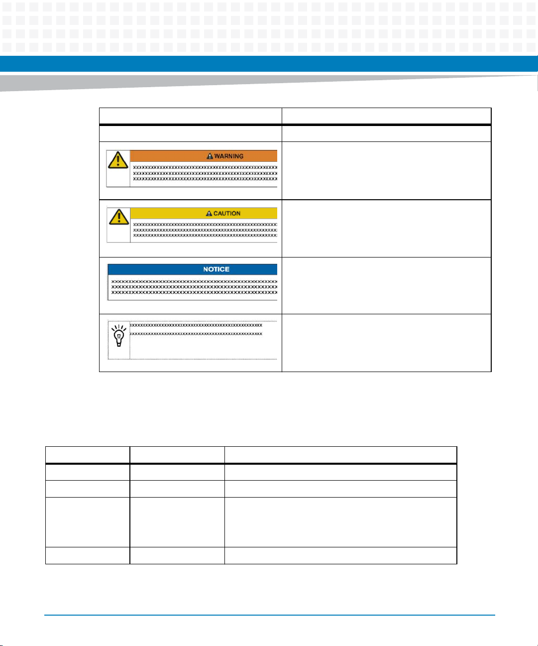
Notation Description
| Logical OR
About this Manual
Indicates a hazardous situation which, if not avoided,
could result in death or serious injury
Indicates a hazardous situation which, if not avoided,
may result in minor or moderate injury
Indicates a property damage message
No danger encountered. Pay attention to important
information
Summary of Changes
This manual has been revised and replaces all prior editions.
Part Number Publication Date Description
6806800P34A September 2012 Initial version
6806800P34B December 2012 Updated Standard Compliances on page 29.
6806800P34C February 2013 Updated Figure "Face Plate" on page 42, Connec tors on page
42, Figure 3-1 on page 41, Figure 3-3 on page 43, Figure
3-4 on page 43, Figure 3-5 on page 44 , Table "Face Plate
LEDs" on page 44 and Figure 6-35 on page 112.
6806800P34D June 2014 Re-branded to Artesyn.
16
PrAMC-7311 Installation and Use (6806800P34D)
Page 17

Safety Notes
This section provides warnings that precede potentially dangerous procedures throughout
this manual. Instructions contained in the warnings must be followed during all phases of
operation, service, and repair of this equipment. You should also employ all other safety
precautions necessary for the operation of the equipment in your operating environment.
Failure to comply with these precautions or with specific warnings elsewhere in this manual
could result in personal injury or damage to the equipment.
Artesyn intends to provide all necessary information to install and handle the product in this
manual. Because of the complexity of this product and its various uses, we do not guarantee
that the given information is complete. If you need additional information, ask your Artesyn
representative.
The product has been designed to meet the standard industrial safety requirements. It must
not be used except in its specific area of office telecommunication industry and industrial
control.
Only personnel trained by Artesyn or persons qualified in electronics or electrical engineering
are authorized to install, remove or maintain the product.
The information given in this manual is meant to complete the knowledge of a specialist and
must not be used as replacement for qualified personnel.
Keep away from live circuits inside the equipment. Operating personnel must not remove
equipment covers. Only factory authorized service personnel or other qualified service
personnel may remove equipment covers for internal subassembly or component replacement
or any internal adjustment.
Do not install substitute parts or perform any unauthorized modification of the equipment or
the warranty may be voided. Contact your local Artesyn representative for service and repair
to make sure that all safety features are maintained.
EMC
This equipment has been tested and found to comply with the limits for a Class A digital device,
pursuant to Part 15 of the FCC Rules. These limits are designed to provide reasonable
protection against harmful interference when the equipment is operated in a commercial
environment. This equipment generates, uses, and can radiate radio frequency energy and, if
not installed and used in accordance with the instruction manual, may cause harmful
interference to radio communications.
PrAMC-7311 Installation and Use (6806800P34D)
17
Page 18

Safety Notes
Operation of this equipment in a residential area is likely to cause harmful interference in which
case the user will be required to correct the interference at his own expense. Changes or
modifications not expressly approved by Artesyn Embedded Technologies could void the
user's authority to operate the equipment. Board products are tested in a representative
system to show compliance with the above mentioned requirements. A proper installation in
a compliant system will maintain the required performance. Use only shielded cables when
connecting peripherals to assure that appropriate radio frequency emissions compliance is
maintained.
Operation
Product Damage
Surface of the Product
High humidity and condensation on the product surface causes short circuits.
Do not operate the product outside the specified environmental limits. Make sure the product
is completely dry and there is no moisture on any surface before applying power.
Overheating and Product Damage
Operating the product without forced air cooling may lead to overheating and thus damage of
the product.
When operating the product, make sure that forced air cooling is available in the shelf.
Data Corruption
If power to the blade is removed while the BIOS is still updating changes to the flash, the
changes will not be saved, and worse, the flash may be corrupted.
Whenever you select the Exit Saving Changes option to save changes to BIOS setup and exit,
do not power the blade down before BIOS reboots.
Product Damage or Loss of Regulatory Compliance
The serial port is meant for development/debug/craft purpose only.
The serial cable is not meant to be connected during normal field operation. The PrAMC-7311
has not been qualified for regulatory compliance with the serial cable connected.
18
PrAMC-7311 Installation and Use (6806800P34D)
Page 19

System Malfunction
Incorrect BIOS settings can cause the system to malfunction.
To rectify mistakes use <F2> on the keyboard to return to setup and restore the system
defaults by pressing <F9>. Alternatively you can press <F2> to return to the BIOS setup and go
to the Exit menu and select Load setup Defaults.
Installation
Damage of the Product and Additional Devices and Modules
Incorrect installation or removal of additional devices or modules may damage the product or
the additional devices or modules.
Before installing or removing additional devices or modules, read the respective
documentation.
Safety Notes
Damage of Circuits
Electrostatic discharge and incorrect installation and removal of the product can damage
circuits or shorten their life.
Before touching the product or electronic components, make sure that your are working in an
ESD-safe environment.
Product Damage
Incorrect installation of the product can cause damage of the product.
Only use handles when installing/removing the product to avoid damage/deformation to the
face plate and/or PCB.
Damage to the Product/Backplane or System Components
Bent pins or loose components can cause damage to the product, the backplane, or other
system components.
Therefore, carefully inspect the product and the backplane for both pin and component
integrity before installation.
PrAMC-7311 Installation and Use (6806800P34D)
19
Page 20

Safety Notes
Artesyn Embedded Technologies and our suppliers take significant steps to ensure there are
no bent pins on the backplane or connector damage to the boards prior to leaving the factory.
Bent pins caused by improper installation or by inserting boards with damaged connectors
could void the Artesyn Embedded Technologies warranty for the backplane or boards.
Cabling and Connectors
Product Damage
The RJ-45 connector(s) on the face plate are either twisted-pair Ethernet (TPE) or E1/T1/J1
interfaces. Connecting an E1/T1/J1 line to an Ethernet connector may damage the product.
Make sure that TPE connectors near your working area are clearly marked as network
connectors.
Verify that the length of an electric cable connected to a TPE bushing does not exceed 100
m.
Make sure the TPE bushing of the product is connected only to safety extra low voltage
circuits (SELV circuits).
If in doubt, ask your system administrator.
Battery
This product utilizes a lithium battery which can only be replaced by qualified service
personnel.
Caution: Risk of explosion if the battery is replaced by an incorrect type. Dispose of used
batteries according to the instructions.
Environment
Always dispose of used AMCs, system components and RTMs according to your country’s
legislation and manufacturer’s instructions.
20
PrAMC-7311 Installation and Use (6806800P34D)
Page 21

Sicherheitshinweise
Dieses Kapitel enthält Hinweise, die potentiell gefährlichen Prozeduren innerhalb dieses
Handbuchs vorrangestellt sind. Beachten Sie unbedingt in allen Phasen des Betriebs, der
Wartung und der Reparatur des Systems die Anweisungen, die diesen Hinweisen enthalten
sind. Sie sollten außerdem alle anderen Vorsichtsmaßnahmen treffen, die für den Betrieb des
Produktes innerhalb Ihrer Betriebsumgebung notwendig sind. Wenn Sie diese
Vorsichtsmaßnahmen oder Sicherheitshinweise, die an anderer Stelle diese Handbuchs
enthalten sind, nicht beachten, kann das Verletzungen oder Schäden am Produkt zur Folge
haben.
Artesyn Embedded Technologies ist darauf bedacht, alle notwendigen Informationen zum
Einbau und zum Umgang mit dem Produkt in diesem Handbuch bereit zu stellen. Da es sich
jedoch um ein komplexes Produkt mit vielfältigen Einsatzmöglichkeiten handelt, können wir
die Vollständigkeit der im Handbuch enthaltenen Informationen nicht garantieren. Falls Sie
weitere Informationen benötigen sollten, wenden Sie sich bitte an die für Sie zuständige
Geschäftsstelle von Artesyn.
Das System erfüllt die für die Industrie geforderten Sicherheitsvorschriften und darf
ausschließlich für Anwendungen in der Telekommunikationsindustrie und im Zusammenhang
mit Industriesteuerungen verwendet werden.
Einbau, Wartung und Betrieb dürfen nur von durch Artesyn ausgebildetem oder im Bereich
Elektronik oder Elektrotechnik qualifiziertem Personal durchgeführt werden. Die in diesem
Handbuch enthaltenen Informationen dienen ausschließlich dazu, das Wissen von
Fachpersonal zu ergänzen, können dieses jedoch nicht ersetzen.
Halten Sie sich von stromführenden Leitungen innerhalb des Produktes fern. Entfernen Sie auf
keinen Fall Abdeckungen am Produkt. Nur werksseitig zugelassenes Wartungspersonal oder
anderweitig qualifiziertes Wartungspersonal darf Abdeckungen entfernen, um Komponenten
zu ersetzen oder andere Anpassungen vorzunehmen.
Installieren Sie keine Ersatzteile oder führen Sie keine unerlaubten Veränderungen am Produkt
durch, sonst verfällt die Garantie. Wenden Sie sich für Wartung oder Reparatur bitte an die für
Sie zuständige Geschäftsstelle von Artesyn Embedded Technologies. So stellen Sie sicher, dass
alle sicherheitsrelevanten Aspekte beachtet werden.
PrAMC-7311 Installation and Use (6806800P34D)
21
Page 22

Sicherheitshinweise
EMV
Das Produkt wurde in einem Artesyn Standardsystem getestet. Es erfüllt die für digitale Geräte
der Klasse A gültigen Grenzwerte in einem solchen System gemäß den FCC-Richtlinien
Abschnitt 15 bzw. EN 55022 Klasse A. Diese Grenzwerte sollen einen angemessenen Schutz
vor Störstrahlung beim Betrieb des Produktes in Gewerbe- sowie Industriegebieten
gewährleisten.
Das Produkt arbeitet im Hochfrequenzbereich und erzeugt Störstrahlung. Bei
unsachgemäßem Einbau und anderem als in diesem Handbuch beschriebenen Betrieb können
Störungen im Hochfrequenzbereich auftreten.
Wird das Produkt in einem Wohngebiet betrieben, so kann dies mit grosser Wahrscheinlichkeit
zu starken Störungen führen, welche dann auf Kosten des Produktanwenders beseitigt werden
müssen. Änderungen oder Modifikationen am Produkt, welche ohne ausdrückliche
Genehmigung von Artesyn durchgeführt werden, können dazu führen, dass der Anwender die
Genehmigung zum Betrieb des Produktes verliert. Boardprodukte werden in einem
repräsentativen System getestet, um zu zeigen, dass das Board den oben aufgeführten EMVRichtlinien entspricht. Eine ordnungsgemässe Installation in einem System, welches die EMVRichtlinien erfüllt, stellt sicher, dass das Produkt gemäss den EMV-Richtlinien betrieben wird.
Verwenden Sie nur abgeschirmte Kabel zum Anschluss von Zusatzmodulen. So ist
sichergestellt, dass sich die Aussendung von Hochfrequenzstrahlung im Rahmen der erlaubten
Grenzwerte bewegt.
Warnung! Dies ist eine Einrichtung der Klasse A. Diese Einrichtung kann im Wohnbereich
Funkstörungen verursachen. In diesem Fall kann vom Betreiber verlangt werden,
angemessene Maßnahmen durchzuführen.
Betrieb
Beschädigung des Produktes
Hohe Luftfeuchtigkeit und Kondensat auf der Oberfläche des Produktes können zu
Kurzschlüssen führen.
Betreiben Sie das Produkt nur innerhalb der angegebenen Grenzwerte für die relative
Luftfeuchtigkeit und Temperatur. Stellen Sie vor dem Einschalten des Stroms sicher, dass sich
auf dem Produkt kein Kondensat befindet.
22
PrAMC-7311 Installation and Use (6806800P34D)
Page 23

Überhitzung und Beschädigung des Produktes
Betreiben Sie das Produkt ohne Zwangsbelüftung, kann das Produkt überhitzt und schließlich
beschädigt werden.
Bevor Sie das Produkt betreiben, müssen Sie sicher stellen, dass das Shelf über eine
Zwangskühlung verfügt.
Fehlerhafter Datenbestand
Wenn sie die Spannungsversorgung des Produkts abschalten, während das BIOS die Daten im
Flash aktualisiert, werden die Änderungen nicht gespeichert oder die Daten im Flash können
beschädigt werden.
Wenn Sie die Option Exit Saving Changes benutzen, um BIOS Änderungen zu speichern, sollten
Sie deshalb immer warten bis das BIOS einen Neustart durchgeführt hat, bevor Sie die
Spannungsversorgung des Produkts abschalten.
Schäden am Produkt oder Verlust der Sicherheitszulassung
Das Anschließen eine Kabels an die serielle Schnittstelle ist nur für Entwicklungs- und
Debugzwecke und nicht für den Betrieb im Feld bestimmt.
Das Produkt wurde nicht für den Betrieb mit angeschlossenem seriellen Kabel zugelassen.
Sicherheitshinweise
Störung des Systembetriebs
Falsche BIOS Einstellungen können den Systembetrieb stören.
Sie können fehlerhafte Einstellungen korrigieren, indem Sie mit der <F2> Taste ins BIOS
zurückkehren und mit der <F9> Taste die Werkseinstellungen wiederherstellen. Alternativ
können Sie mit <F2> ins BIOS zurückkehren und im Exit Menü den Eintrag Load Setup Defaults
auswählen.
Installation
Beschädigung des Produktes und von Zusatzmodulen
Fehlerhafte Installation von Zusatzmodulen, kann zur Beschädigung des Produktes und der
Zusatzmodule führen.
Lesen Sie daher vor der Installation von Zusatzmodulen die zugehörige Dokumentation.
PrAMC-7311 Installation and Use (6806800P34D)
23
Page 24

Sicherheitshinweise
Beschädigung von Schaltkreisen
Elektrostatische Entladung und unsachgemäßer Ein- und Ausbau des Produktes kann
Schaltkreise beschädigen oder ihre Lebensdauer verkürzen.
Bevor Sie das Produkt oder elektronische Komponenten berühren, vergewissern Sie sich, daß
Sie in einem ESD-geschützten Bereich arbeiten.
Beschädigung des Produktes
Fehlerhafte Installation des Produktes kann zu einer Beschädigung des Produktes führen.
Verwenden Sie die Handles, um das Produkt zu installieren/deinstallieren. Auf diese Weise
vermeiden Sie, dass das Face Plate oder die Platine deformiert oder zerstört wird.
Beschädigung des Produktes, der Backplane oder von System Komponenten
Verbogene Pins oder lose Komponenten können zu einer Beschädigung des Produktes, der
Backplane oder von Systemkomponenten führen.
Überprüfen Sie daher das Produkt sowie die Backplane vor der Installation sorgältig und stellen
Sie sicher, dass sich beide in einwandfreien Zustand befinden und keine Pins verbogen sind.
24
PrAMC-7311 Installation and Use (6806800P34D)
Page 25

Sicherheitshinweise
Artesyn Embedded Technologies und unsere Zulieferer unternehmen größte Anstrengungen
um sicherzustellen, dass sich Pins und Stecker von Boards vor dem Verlassung der
Produktionsstätte in einwandfreiem Zustand befinden. Verbogene Pins, verursacht durch
fehlerhafte Installation oder durch Installation von Boards mit beschädigten Steckern kann die
durch Artesyn Embedded Technologies gewährte Garantie für Boards und Backplanes
erlöschen lassen.
Kabel und Stecker
Beschädigung des Produktes
Bei den RJ-45 Steckern, die sich an dem Produkt befinden, handelt es sich entweder um
Twisted-Pair-Ethernet (TPE) oder um E1/T1/J1-Stecker. Beachten Sie, dass ein versehentliches
Anschließen einer E1/T1/J1-Leitung an einen TPE-Stecker das Produkt zerstören kann.
Kennzeichnen Sie deshalb TPE-Anschlüsse in der Nähe Ihres Arbeitsplatzes deutlich als
Netzwerkanschluss.
Stellen Sie sicher, dass die Länge eines mit Ihrem Produkt verbundenen TPE-Kabels 100 m
nicht überschreitet.
Das Produkt darf über die TPE-Stecker nur mit einem Sicherheits-Kleinspannungs-
Stromkreis (SELV) verbunden werden.
Umweltschutz
Entsorgen Sie alte Batterien und/oder Blades/Systemkomponenten/RTMs stets gemäß der in
Ihrem Land gültigen Gesetzgebung und den Empfehlungen des Herstellers.
PrAMC-7311 Installation and Use (6806800P34D)
25
Page 26

Sicherheitshinweise
26
PrAMC-7311 Installation and Use (6806800P34D)
Page 27

Introduction
1.1 Features
The PrAMC-7311 is designed as a hot-swappable, high-performance and low-power dual-core
processor AMC module and can be used as a processing and system controller module as
defined in the Micro Telecom Computing Architecture (μTCA) standard. The module works in
conjunction with an AMC carrier card and extends the processing power and functionalities of
the carrier card. It is based on the Intel Core i7-2655LE processor and the Intel QM67 chipset
and offers powerful processing capability with low power consumption, large memory
capacity, USB2.0 port Connected SD card, and high I/O bandwidth via face plate and rear AMC
fabric I/O interfaces.
It is available as a mid-size AMC module.
Table 1-1 Features
Feature Description
Chapter 1
Processor Intel Core i7-2655LE LV processor (4 MB L3 cache) 2.2 GHz
Memory Support for dual channel DDR3-1333 registered memory and for 2 Gbit
/ 4 Gbit SDRAMs for 4 GB / 8 GB capacity, 4Gbit dual -die SDRAMS for 16GB
capacity
Quad Gigabit Ethernet
(SerDes)
1 Gbit Fast Ethernet Intel i350-AM4 (PCIe x4)
USB 2.0 Based SD card Optional 2GB MicroSD card
PCIe Interface One PCIe x8 interface
SATA Interface Two Gen 2 SATA channels via AMC fabric I/O interface
RS-232 Port Face plate RJ-45 port
Core Chip Intel BD82QM67 Platform Controller Hub (PCH)
MMC Renesas H8S/2472 microcontroller
Form Factor Single width mid-size AMC (73.5 mm x 181.5 mm)
Intel i350-AM4 (PCIe x 4) Dual 1 Gbit SerDes interface via AMC fabric I/O
interface, Supports PXE boot
Face plate RJ-45 port
Supports PXE boot
Configurable as two PCIe x4 interfaces
Supported via AMC fabric I/O interface
Implementing Pigeon Point MMC firmware
PrAMC-7311 Installation and Use (6806800P34D)
27
Page 28
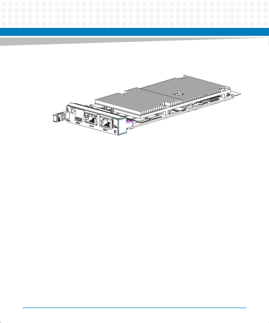
Introduction
Figure 1-1 Mid-Size AMC
28
PrAMC-7311 Installation and Use (6806800P34D)
Page 29

1.2 Standard Compliances
This product meets the following standards.
Table 1-2 Standard Compliances
Standard Description
Introduction
UL 60950-1(2nd edition)
EN 60950-1(2nd edition)
IEC 60950-1(2nd edition)
CAN/CSA C22.2 No 60950-1(2nd edition)
CISPR 22
CISPR 24
EN 55022
EN 55024
FCC Part 15
Industry Canada ICES-003
VCCI Japan(tested but not submitted to agency)
AS/NZS CISPR 22(tested but not submitted to agency)
EN 300 386
NEBS Standard GR-1089 CORE
NEBS Standard GR-63-CORE
ETSI EN 300019 series
AMC.0 Defines mechanics, blade dimensions, power distribution,
Legal safety requirements (Reference CSA file LR 49303)
Isolation is functional insulation only complying with 60950-
1 clause 5.3.4c
R
LR 49303
EMC requirements (legal) on system level (predefined
Artesyn system)
Environmental requirements
power and data connectors, and system management
PrAMC-7311 Installation and Use (6806800P34D)
29
Page 30
Introduction
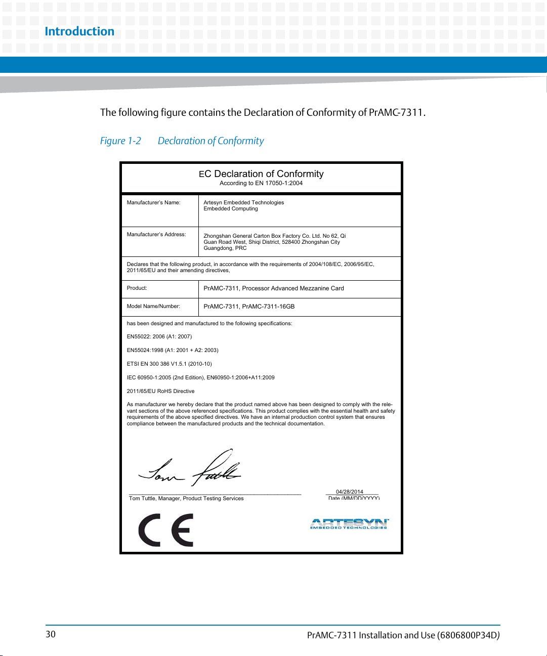
The following figure contains the Declaration of Conformity of PrAMC-7311.
Figure 1-2 Declaration of Conformity
E
C Declaration of Conformity
According to EN 17050-1:2004
Manufacturer’s Name:
Manufacturer’s Address:
Declares that the following product, in accordance with the requirements of 2004/108/EC, 2006/95/EC,
2011/65/EU and their amending directives,
Product:
Model Name/Number:
has been designed and manufactured to the following specifications:
EN55022: 2006 (A1: 2007)
EN55024:1998 (A1: 2001 + A2: 2003)
ETSI EN 300 386 V1.5.1 (2010-10)
IEC 60950-1:2005 (2nd Edition), EN60950-1:2006+A11:2009
2011/65/EU RoHS Directive
As manufacturer we hereby declare that the product named above has been designed to comply with the rele-
vant sections of the above referenced specifications. This product complies with the essential health and safety
requirements of the above specified directives. We have an internal production control system that ensures
compliance between the manufactured products and the technical documentation.
___________________________________________________ ___
Tom Tuttle, Manager, Product Testing Services Date (MM/DD/YYYY)
Artesyn Embedded Technologies
Embedded Computing
Zhongshan General Carton Box Factory Co. Ltd. No 62, Qi
Guan Road West, Shiqi District, 528400 Zhongshan City
Guangdong, PRC
PrAMC-7311, Processor Advanced Mezzanine Card
PrAMC-7311, PrAMC-7311-16GB
04/28/2014_____
30
PrAMC-7311 Installation and Use (6806800P34D)
Page 31

1.3 Ordering Information
When ordering board variants, use the order numbers given in the following table.
Table 1-3 Available Board Variants
Order Number Assembly Number Description
PrAMC-7311 0106810M01C AMC with Intel Core i7 processor, 4GB
PrAMC-7311-16GB 0106810M03B AMC with Intel Core i7 processor, 16GB
Introduction
DDR3- mid size
DDR3- mid size
PrAMC-7311 Installation and Use (6806800P34D)
31
Page 32

Introduction
32
PrAMC-7311 Installation and Use (6806800P34D)
Page 33

Hardware Preparation and Installation
2.1 Overview
In this chapter you can find information on the following topics:
Unpacking and inspecting the module
Environmental and power requirements
Configuring the module
Installing module accessories
Module installation and removal
2.2 Unpacking and Inspecting the Module
Chapter 2
Damage of Circuits
Electrostatic discharge and incorrect installation and removal of the blade can damage circuits
or shorten their life.
Before touching the blade or electronic components, make sure that your are working in an
ESD-safe environment.
Shipment Inspection
To inspect the shipment, perform the following steps.
1. Verify that you have received all items of your shipment:
PrAMC-7311 module
Any optional items ordered
2. Check for damage and report any damage or differences to the customer service.
PrAMC-7311 Installation and Use (6806800P34D)
33
Page 34

Hardware Preparation and Installation
3. Remove the desiccant bag shipped together with the module and dispose of it
according to your country’s legislation.
The blade is thoroughly inspected before shipment. If any damage occurred during
transportation or any items are missing, please contact our customer's service immediately.
2.3 Environmental and Power Requirements
The following environmental and power requirements are applicable to the blade.
2.3.1 Environmental Requirements
34
You must make sure that the blade, when operated in your particular system configuration,
meets the environmental requirements specified below.
Operating temperatures refer to the temperature of the air circulating around the blade and not
to the component temperature.
Blade Damage
High humidity and condensation on the blade surface causes short circuits.
Do not operate the blade outside the specified environmental limits. Make sure the blade is
completely dry and there is no moisture on any surface before applying power.
PrAMC-7311 Installation and Use (6806800P34D)
Page 35

Hardware Preparation and Installation
Table 2-1 Environmental Requirements
Requirement Operating Non-Operating
Temperature +0 ºC (32 °F) to +55 ºC (131 °F) (normal
operation) according to NEBS Standard GR63-CORE
Temp. Change +/- 0.25 ºC/min according to NEBS Standard
GR-63-CORE
Rel. Humidity 5% to 90% non-condensing according to
Artesyn-internal environmental
requirements
Vibration 0.1 g from 5 to 200 Hz and back to 5 Hz at a
rate of 0.25 octave/minute
Shock Half-sine, 11 m/Sec, 30 mSec/Sec
Free Fall - 1,200 mm/all edges and corners
2
-40 ºC (-40 °F) to +70 ºC (158 °F) (may be
further limited by installed accessories)
+/- 0.25 ºC/min
5% to 95% non-condensing according to
Artesyn-internal environmental
requirements
5-20 Hz at 0.01 g
20-200 Hz at -3.0 dB/octave
Random 5-20 Hz at 1 m
Random 20-200 Hz at -3 m/Sec
Blade level packaging
Half-sine, 6 mSec at 180 m/Sec
1.0 m (packaged) per ETSI 300 019-2-2
(Blade level packaging)
100 mm (unpacked) per GR-63-CORE
2
/Hz
2
/Sec
2.3.2 Thermal Requirements
3
2
2
The minimum airflow requirements for the AdvancedTCA platforms are 13 CFM for the 2.2 GHz
PrAMC-7311 module platforms. This is with a maximum operating temperature limit of 55 °C
(131 °F).
Contact your Artesyn sales representative for current information on the detailed thermal
information including airflow and resistance of the PrAMC-7311.
PrAMC-7311 Installation and Use (6806800P34D)
35
Page 36

Hardware Preparation and Installation
2.3.3 Power Requirements
Make sure that the module is used on an approved AdvancedTCA carrier board in an
AdvancedTCA shelf connected to -48 VDC up to -60 VDC, for use in a restricted access area only
by trained personnel. All circuits are safety-extra-low-voltage (SELV) under normal operating
conditions, and are not subject to over voltages/transients.
Table 2-2 DC System Power Requirements
Feature Value
Rated voltage 12 VDC
Operating voltage 10 VDC to 14 VDC
Input current 5 A at 12 V
Power dissipation 30 W (Typical)
60 W (max)
36
The module provides two independent power inputs according to the AdvancedTCA
specification.
PrAMC-7311 Installation and Use (6806800P34D)
Page 37

Hardware Preparation and Installation
2.4 Module Installation and Removal
This section describes how to install and remove an AMC module.
Damage of Circuits
Electrostatic discharge and incorrect product installation and removal can damage circuits or
shorten their life.
Before touching the product or electronic components, make sure that you are working in an
ESD-safe environment.
Product Malfunctioning
Incorrect product installation and removal can result in product malfunctioning.
When plugging the product in or removing it, do not press on the face plate but use the handles.
Limitization of Operating Temperature Range
Installing AMC modules with small operating temperature ranges onto the blade may further
restrict the operating temperature range of the blade.
Make sure that the operating temperature of any installed AMC modules and the blade as a
bundle are within allowed limits.
Installation Procedure
The following describes how to install an AMC module into an AMC bay of the base board. The
installation procedure assumes that the AMC module is being hot-inserted, that means the
base board is powered. The procedure for the cold insertion, that means the base board is not
powered, is the same, except that you need not wait for the blue LED indications to proceed.
1. Make sure you are in an ESD-safe environment.
2. Identify the AMC bay to be used for the installation.
3. If the required AMC bay is occupied by an AMC filler panel, you will need to remove
the filler panel before proceeding with the installation procedure. The removal
procedure for the filler panel is the same as described in the Removal procedure
which follows immediately after this procedure. Ignore steps that mention the blue
LED.
PrAMC-7311 Installation and Use (6806800P34D)
37
Page 38

Hardware Preparation and Installation
4. Ensure that AMC module handle is in the extracted position: pulled outward, away
from the face plate.
5. Using your thumb, apply equal and steady pressure on the face plate as necessary
to carefully slide the AMC module into the guides rails.
6. Continue to gently push the module along the guide rails till the module is fully
engaged with the connector. Avoid using excessive force during this operation.
7. Wait for the blue LED to glow. The blue LED glows when the AMC module is
completely engaged with the connector.
8. Press module handle inwards toward the face plate to lock the AMC module on
AMC bay.
9. Wait for the blue LED to perform a series of long blinks. The blue LED blinks when
the handle is locked in position indicating module detection and activation by the
carrier board.
38
10.Observe blue LED status/activity. The module is fully installed when the blue LED
stops blinking and stays OFF.
Removal Procedure
The following describes how to remove an AMC module from the base board. The procedure
assumes that the base board is powered. If it is not powered, the steps regarding the blue LED
can be ignored and skipped.
1. Make sure you are in an ESD safe environment.
2. Remove any cables that are connected to the AMC module face plate connectors.
3. Gently pull the module latch outward, approximately 3 mm from its locked
position.
PrAMC-7311 Installation and Use (6806800P34D)
Page 39

Hardware Preparation and Installation
4. Wait for the blue LED to first perform short blinks, and then glow persistently.
Data Loss
Removing the blade with the blue LED still blinking causes data loss.
Wait until the blue LED is permanently illuminated, before removing the blade.
5. Once the blue LED glows persistently, gently pull the AMC module handle outward
to disconnect the module from the AMC connectors. Continue to gently slide the
module outward along the guide rails.
Poor Shelf Cooling and EMC Compliance Violation
An empty AMC bay may result in poor shelf cooling and strong EMC radiation and thus lead to
EMC compliance violation.
Therefore, always cover empty or unused AMC bays with a filler panel.
6. Install AMC filler panel.
PrAMC-7311 Installation and Use (6806800P34D)
39
Page 40

Hardware Preparation and Installation
40
PrAMC-7311 Installation and Use (6806800P34D)
Page 41

Controls, LEDs and Connectors
3.1 Overview
This chapter describes:
Mechanical layout of the module
Face plate connectors and LEDs
3.2 Board Layout
The following figure provides an overview of the mechanical layout of the module
components.
Figure 3-1 Mechanical Layout
Chapter 3
PrAMC-7311 Installation and Use (6806800P34D)
41
Page 42

Controls, LEDs and Connectors
3.3 Face Plate Connectors and LEDs
The following figure shows the face plates of the PrAMC-7311 modules.
Figure 3-2 Face Plate
3.3.1 Connectors
The following connectors are available on the face plate.
Serial - RJ45
Ethernet
USB
42
PrAMC-7311 Installation and Use (6806800P34D)
Page 43

Controls, LEDs and Connectors
The serial interface COM can be used to connect a console. You can find its signal description in
the following figure.
Figure 3-3 Serial Console RJ45 Connector Pinout
The Ethernet interface ETH is used to establish an Ethernet connection. You can find its signal
description in the following figure.
Figure 3-4 Ethernet Connector Pinout
PrAMC-7311 Installation and Use (6806800P34D)
43
Page 44

Controls, LEDs and Connectors
The USB 2.0 interface USB can be used to connect other USB devices. You can find its signal
description in the following figure.
Figure 3-5 USB Micro-B Connector Pinout
3.3.2 LEDs
Figure 3-2 shows the LEDs on the face plate.
The meaning of the LEDs is described in the following table.
Table 3-1 Face Plate LEDs
Name Color Description
OOS Red Out Of Service
This LED is controlled by higher layer software, such as middleware or
applications.
The IPMC turns this LED on when the payload gets activated and turns
it off when the payload gets de-activated.
IS Green In Service
This LED is controlled by higher layer software, such as middleware or
applications.
The IPMC turns this LED off when the payload gets either activated or
de-activated.
44
PrAMC-7311 Installation and Use (6806800P34D)
Page 45

Table 3-1 Face Plate LEDs (continued)
Name Color Description
HS Blue FRU State Machine
During module installation:
Permanently blue: On-board IPMC powers up.
Blinking blue: Module communicates with shelf manager.
OFF: Module is active.
During module removal:
Blinking blue: Module notifies shelf manager of its desire to deactivate.
Permanently blue: Module is ready to be extracted.
ACT type Green ACTIVITY type
Blinking: When Packets are Txed/Rxed
Off: No Activity
Link status Yellow Link status
On: Link
Off: No Link
Controls, LEDs and Connectors
PrAMC-7311 Installation and Use (6806800P34D)
45
Page 46

Controls, LEDs and Connectors
46
PrAMC-7311 Installation and Use (6806800P34D)
Page 47

Functional Description
4.1 Overview
The main components of the PrAMC-7311 are:
Intel Core
Intel BD82QM67 PCH (Platform Controller Hub)
Intel i350-AM4 Gigabit Ethernet Controller (Quad Port)
4GB DDR3 memory (Supports 1333,1066 with ECC)
USB Accessed SD card
They are described in more detail in the following sections.
™
i7-2655LE Processor (Central Processing Unit)
Chapter 4
PrAMC-7311 Installation and Use (6806800P34D)
47
Page 48

Functional Description
4.2 Block Diagram
The following figure provides an overview of the main function blocks of the PrAMC-7311 and
how they are interconnected.
Figure 4-1 Block Diagram
AMC Front Panel AMC Edge
RJ45
Integrated
Mag & LEDs
MicroUSB
Type-B
Connector
RJ45
Connector
text
text
MicroSD
Connector
text
text
text
text
text
2 GB DDR3 SDRAM
9 x 2Gb x 8
64- bit + 8-bit ECC
text
text
text
text
text
2 GB DDR3 SDRAM
9 x 2Gb x 8
64- bit + 8-bit ECC
UART
UART
Interface
1G Ethernet
PCH SMBus
SPD
text
text
USB2240
USB Flash
Media
Controller
LP47N 217N
LP47N 217N
DDR3, 72 bit
1066/1333
PCH SMBus
SPD
DDR3, 72 bit
1066/1333
SMBus to OnBoard Device
USB0
USB1
Port80
On- Board Power
Flash
E2PROM
DDR3
Channel A
DDR3
Channel B
LPC
Isolation
Isolation
Hot- Swap Switch,LEDs
SPI
Intel
Powerville i350
QUAD 1G
SPI
Eth Controller
X4 PCIe
PEG
Intel
Core i7- 2655LE
Sandy Bridge
Clock
Intel
BD82 QM67
Cougar Point
PCH
FDI DMI
Latch
On Board
Power
Conversion
Power monitoring
Signals from PCH
Isolation
Buffer
Power monitoring
boot Control
LPC
SOL UART
Power &
Status
Signals
Power Control
Signals
1G Ethernet SERDES
1G Ethernet SERDES
SM bus for SOL
XDP
Local PCIe Clock
SATA
SATA
X4 PCIe
X4 PCIe
signals
Isolation
Boot
Seletion
Logic
BIOS
Latch
MMC
Renesas
H8S/ 2472
Payload Enable
Power
sequence
Control &
Monitoring
Logic
(UCD 90160)
To UCD90160
SPI Flash
AT25DF 641A
64Mbit
SPI Flash
AT25DF 641A
64Mbit
SM bus for SOL
I2C
PS0/PS1/ GA[2:0]
I2C3
AMC Port 0
AMC Port 1
AMC Port 2
AMC Port 3
AMC Port 4-7
AMC Port 8-11
IPMB-
AMC_ Enable
3.3 V Mgmt
Temp
Sensor
FRU/SDR
L
12V
48
PrAMC-7311 Installation and Use (6806800P34D)
Page 49

Functional Description
4.3 CPU
The PrAMC-7311 uses the high performance and low power Core™ i7-2655LE Processor
operating with a 2.2 GHz core frequency. Please see the Intel documentation for details
regarding this device.
4.4 Platform Controller Hub
The PrAMC-7311 utilizes the Intel BD82QM67 PCH (Platform Controller Hub). Please see Intel
documentation for details regarding this device.
4.5 I350-AM4 Quad Port Gigabit Ethernet Controller
The PrAMC-7311 uses the Intel i350-AM4 Quad Port Gigabit Ethernet Controller to provide 1
Gigabit Copper interface to Front Panel (RJ45 With integrated Magnetics) two 1000base-BX
SERDES interfaces to the AMC fabric interface. The Gigabit Ethernet Controller resides on PCI
Express Interface of the Intel i7-2655LE CPU.
Please see Intel documentation for details regarding this device.
4.6 DDR3 Memory
The PrAMC-7311 uses 18 Samsung K4B2G0846D-HCH9 devices to provide 4GB of ECC
protected DDR3 memory supporting 1333 MT/s operation.
The PrAMC-7311-16GB uses 18 micron MT41J1G8THE-15E devices to provide 16GB of ECC
protected DDR3 memory supporting 1066 MT/s operation..
4.7 USB Accessed SD card
The PrAMC-7311 supports an optional MicroSD card which serves as Persistent memory for the
purposes of Storing an OS and local storage. The MicroSD card is accessed through the
USB2240 controller which is connected to the USB 0 port of the PCH.
PrAMC-7311 Installation and Use (6806800P34D)
49
Page 50

Functional Description
4.8 Module Management Controller
The PrAMC-7311 provides the Module Management Controller (MMC) based on the
H8S/2472, an 16-bit RISC micro controller of the AVR family from Renesas.
The following are the key features:
H8S/2472 micro controller implementing Pigeon Point MMC firmware
Supports IPMB interface via the AMC fabric I/O interface
Supports LPC(LPC to Serial) interface with QM67 PCH, and Header for it's own
programming
Controls power on signal for the module
Controls Status and Health of the module with the help of sensors and Signals
50
PrAMC-7311 Installation and Use (6806800P34D)
Page 51

Address Mapping
5.1 Overview
The information in this chapter might be helpful for developing your own operating system.
5.2 Memory Address Mapping
The following table shows the memory range of the PrAMC-7311.
Table 5-1 Memory Range
Base Address Size Device
0x0000.0000 0x7FFF.FFFF Main Memory (2 GB)
0xFFE0.0000 0xFFFF.FFFF Boot Flash FWH (2 MB)
Chapter 5
The following table explains the FWH address mapping when 1 MB booting FWH and 1 MB
redundant FWH are supported.
Table 5-2 FWH Address Map
Boot Type Boot FWH Selection Address Range
Primary Lower 1 MB sector (Secondary FWH) 0xFFE0.0000 -
0xFFEF.FFFF
Primary Higher 1 MB sector (Primary FWH = Current Boot FWH) 0xFFF0.0000 -
0xFFFF.FFFF
Secondary Lower 1 MB sector (Secondary FWH = Current Boot FWH) 0xFFF0.0000 -
0xFFFF.FFFF
Secondary Higher 1 MB sector (Primary FWH) 0xFFE0.0000 -
0xFFEF.FFFF
PrAMC-7311 Installation and Use (6806800P34D)
51
Page 52

Address Mapping
5.2.1 System Memory Map
Figure 5-1 System Memory Map
FFFF FFFFh
FEE0 0000h
FEC0 0000h
E000 0000h
0100 0000h
00F0 0000h
Flash
MSI Interrupts
APIC
PCI Express
Configuration Space
DMI Interface
(Subtractive Decode)
IGD
IGGTT
TSEG
DPR
Main Memory
ISA Hole (Otional)
4 GB
4 GB-Flash
4 GB-18 MB
4 GB-20 MB
4 GB-512 MB
(BARs, internal graphic ranges,
PCI express port, CHAPADR
could be here)
TOLUD
TSEG_BASE
16MB
15 MB
52
0010 0000h
0000 0000h
Main Memory
1 MB
DOS Compatible
Memory
0
PrAMC-7311 Installation and Use (6806800P34D)
Page 53

5.2.2 Flash Layout
BIOS can be supported from either firmware hub (LPC) or on SPI, for PrAMC-7311 it is designed
to support from SPI flash and as usually the ME and GbE technology supported firmware also
reside on flash devices only so that total firmware's can be combined into single image and
going to be placed into the SPI flash. PrAMC-7311 support of two flash devices with 8MB each
and with the help of MMC the particular flash can be selected for boot the BIOS, by default
system boot from flash device 0 because default selection line enabled on SPI is of #CS0. Below
the figure is the flash composition to support the BIOS, GbE, ME technologies.
Figure 5-2 Flash Layout
Address Mapping
5.3 I/O Address Mapping
The I/O address ranges of all onboard functional units are shown in the next table.
Table 5-3 I/O Address Mapping
Address Range Device
0x000 - 0x01F DMA Controller
0x020 - 0x02D Interrupt controller
0x030 - 0x03D Interrupt Controller
0x040 - 0x043 Timer
PrAMC-7311 Installation and Use (6806800P34D)
53
Page 54

Address Mapping
Table 5-3 I/O Address Mapping (continued)
Address Range Device
0x050 - 0x053 Timer
0x070 - 0x077 RTC
0x080 LPC Port 80
0x080 - 0x091 DMA Controller
0x093 - 0x09F DMA Controller
0x0A0 - 0x0B1 Interrupt Controller
0x0B4 - 0x0BD Interrupt Controller
0x0C0 - 0x0DF DMA Controller
0x170 - 0x177 SATA
0x1F0 - 0x1F7 SATA
0x376 SATA
0x3F6 SATA
0x4D0 - 0x4D1 Interrupt Controller
5.4 PCI Device Mapping
The following table lists the devices on the PCI bus and their IDs.
Table 5-4 PCI Device Mapping
Bus Dev Fun Device DID Vendor Part
00 00 0 Host Bridge 35B0 Intel 3100 A1
00 00 1 DRAM Controller, Error Status 35B1 Intel 3100 A1
00 01 0 EDMA Engine 35B5 Intel 3100 A1
00 02 0 PCI-to-PCI Bridge (PCIe port A0 x8 or x4) 35B6 Intel 3100 A1
00 03 0 PCI-to-PCI Bridge (PCIe port A1 x4) 35B7 Intel 3100 A1
00 08 0 Extended Configuration 35C8 Intel 3100 A1
00 1C 0 PCI-to-PCI Bridge (PCIe port B) 2690 Intel 3100 A1
54
PrAMC-7311 Installation and Use (6806800P34D)
Page 55

Address Mapping
Table 5-4 PCI Device Mapping (continued)
Bus Dev Fun Device DID Vendor Part
00 1D 0 USB 1.1 OHCI Controller 1 2688 Intel 3100 A1
00 1D 1 USB 1.1 OHCI Controller 2 (Not used) 2689 Intel 3100 A1
00 1D 7 USB 2.0 EHCI Host Controller 268C Intel 3100 A1
00 1E 0 PCI-to-PCI Bridge 244E Intel 3100 A1
00 1F 0 ISA Bridge (LPC Interface) 2670 Intel 3100 A1
00 1F 2 SATA Host Controller 2680 Intel 3100 A1
00 1F 3 SMBus Controller 269B Intel 3100 A1
20 00 0 Gigabit Ethernet Controller (Port 0) 1060 Intel 82571EB D0
20 00 1 Gigabit Ethernet Controller (Port 1) 1060 Intel 82571EB D0
21 00 0 10/100Mbit Ethernet Controller 1229 Intel 82551QM A1
5.5 GPIO Mapping
The following table shows the relation between the GPIO signals and pins.
Table 5-5 GPIO Mapping
Signal GPIO Pin# Power Rail Description
DRAMRST_CNT
RL_PCH
PCH_HOTN GPIO74 C13 VCC3V3_A PCH's Thermal status report signal to MMC
NMI GPIO8 C10 VCC3V3_A NMI from MMC to PCH
PCH_GPIO27 GPIO27 E16 VCC3V3_A General Purpose IO pin to MMC from PCH
PCH_GPIO49_T
RALERT
SATA2GP GPIO36 V8 VCC3V3_S Optional GPI from Device Present pin of SATA slim
PrAMC-7311 Installation and Use (6806800P34D)
GPIO60 A12 VCC3V3_A Controls DDR3 RESET signal from CPU
GPIO49 V3 VCC3V3_S General Purpose IO pin to MMC from PCH
line Power connector
55
Page 56

Address Mapping
5.6 SMBus Addressing
The following table lists the devices on the SMBusses and their addresses.
Table 5-6 SMBus Addressing
SMBus Device Address
SMBus 0 SPD1(U9) 0xA0
SMBus 0 SPD2(U21) 0xA4
5.7 Interrupt Routing
Override default configuration parameters for the IRQ priority table. This table is used by the
PlatformCsm component and describes the list of interrupts to assign to device interrupt line
registers (0x3c). Only non-zero values are considered for IRQ assignment.
Config BOARD_PCI_IRQ_1, 11 // first valid IRQ number.
Config BOARD_PCI_IRQ_2, 10 // next valid IRQ number.
Config BOARD_PCI_IRQ_3, 9 // next valid IRQ number.
Config BOARD_PCI_IRQ_4, 0 // next valid IRQ number.
Config BOARD_PCI_IRQ_5, 0 // next valid IRQ number.
Config BOARD_PCI_IRQ_6, 0 // next valid IRQ number.
Config BOARD_PCI_IRQ_7, 0 // last valid IRQ number.
Create PCI Device objects with IRQ routing. Interrupt pin objects (i.e., PIRQA, PIRQB, etc.)
available on this system are defined in the Module.def file of the platform module.
Table 5-7 Interrupt Routing
Name Bus Device Fn PinA PinB PinC PinD Slot
PciDev IntelImc 0 0 0 PIRQA PIRQB PIRQC PIRQD
PciDev PcieGfxPort 0 1 0 PIRQA PIRQB PIRQC PIRQD
56
PrAMC-7311 Installation and Use (6806800P34D)
Page 57

Address Mapping
Table 5-7 Interrupt Routing (continued)
Name Bus Device Fn PinA PinB PinC PinD Slot
PciDev PcieGfx INITI
AL_P
EG_B
US_
NUM
BER
PciDev InternalGraphics 0 2 0 PIRQA 0 0 0
PciDev Dev4 0 4 0 PIRQA PIRQB PIRQC PIRQD
PciDev Dev6 0 6 0 PIRQD PIRQA PIRQB PIRQC
PciDev MePerfCounter 0 7 0 PIRQA 0 0 0
PciDev Heci 0 22 0 PIRQA PIRQD PIRQC PIRQB
PciDev Ethernet 0 25 0 PIRQE 0 0 0
0 0 PIRQA 0 0 0 4
PciDev Ehci2 0 26 0 PIRQA PIRQF PIRQC PIRQD
PciDev Audio 0 27 0 PIRQG 0 0 0
PciDev PcieRoot 0 28 0 PIRQA PIRQB PIRQC PIRQD
PciDev Ehci1 0 29 0 PIRQH PIRQD PIRQA PIRQC
PciDev Lpc 0 31 0 PIRQF PIRQD PIRQC PIRQA
PciDev PcieSlot1 INITI
AL_P
CIE_
POR
T0
PciDev PcieSlot2 INITI
AL_P
CIE_
POR
T1
PciDev PcieSlot3 INITI
AL_P
CIE_
POR
T2
0 0 PIRQA PIRQB PIRQC PIRQD 5
0 0 PIRQB PIRQC PIRQD PIRQA 6
0 0 PIRQC PIRQD PIRQA PIRQB 7
PrAMC-7311 Installation and Use (6806800P34D)
57
Page 58

Address Mapping
Table 5-7 Interrupt Routing (continued)
Name Bus Device Fn PinA PinB PinC PinD Slot
PciDev PcieSlot4 INITI
AL_P
CIE_
POR
T3
PciDev PcieSlot5 INITI
AL_P
CIE_
POR
T4
PciDev PcieSlot6 INITI
AL_P
CIE_
POR
T5
PciDev PcieSlot7 INITI
AL_P
CIE_
POR
T6
PciDev PcieSlot8 INITI
AL_P
CIE_
POR
T7
PciDev PcieSlot1 INITI
AL_P
CI_B
US_
NUM
BER
PciDev PcieSlot2 INITI
AL_P
CI_B
US_
NUM
BER
0 0 PIRQD PIRQA PIRQB PIRQC 8
0 0 PIRQA PIRQB PIRQC PIRQD 9
0 0 PIRQB PIRQC PIRQD PIRQA 10
0 0 PIRQC PIRQD PIRQA PIRQB 11
0 0 PIRQD PIRQA PIRQB PIRQC 12
0 0 PIRQF PIRQG PIRQH PIRQE 1
1 0 PIRQG PIRQF PIRQE PIRQH 2
58
PrAMC-7311 Installation and Use (6806800P34D)
Page 59

Address Mapping
Table 5-7 Interrupt Routing (continued)
Name Bus Device Fn PinA PinB PinC PinD Slot
PciDev PcieSlot3 INITI
AL_P
CI_B
US_
NUM
BER
The following define the PCH IRQ Routing configurations.
Config PCH_D22IP, 0x00002321 // Device 22 Interrupt Pin register.
Config PCH_D24IP, 0x00000001 // Device 24 Interrupt Pin register.
Config PCH_D25IP, 0x00000001 // Device 25 Interrupt Pin register.
Config PCH_D26IP, 0x40004321 // Device 26 Interrupt Pin register.
5 0 PIRQC PIRQE PIRQG PIRQF 3
Config PCH_D27IP, 0x00000001 // Device 27 Interrupt Pin register.
Config PCH_D28IP, 0x43214321 // Device 28 Interrupt Pin register.
Config PCH_D29IP, 0x00014321 // Device 29 Interrupt Pin register.
Config PCH_D31IP, 0x03243200 // Device 31 Interrupt Pin register.
Config PCH_D22IR, 0x1230 // Device 22 Interrupt Route register.
Config PCH_D24IR, 0x3210 // Device 24 Interrupt Route register.
Config PCH_D25IR, 0x7654 // Device 25 Interrupt Route register.
Config PCH_D26IR, 0x3250 // Device 26 Interrupt Route register.
Config PCH_D27IR, 0x3216 // Device 27 Interrupt Route register.
Config PCH_D28IR, 0x3210 // Device 28 Interrupt Route register.
Config PCH_D29IR, 0x2037 // Device 29 Interrupt Route register.
Config PCH_D31IR, 0x0230 // Device 31 Interrupt Route register.
PrAMC-7311 Installation and Use (6806800P34D)
59
Page 60

Address Mapping
60
PrAMC-7311 Installation and Use (6806800P34D)
Page 61

Basic Input Output System
6.1 BIOS
The Basic Input Output System (BIOS) provides an interface between the operating system and
the hardware of the blade. It is used for hardware configuration. Before loading the operating
system, BIOS performs basic hardware tests and prepares the blade for the initial boot-up
procedure.
BIOS Setup enables configuration of the following features:
Hardware set-up utility for setting configuration data
Multi-boot for a flexible boot order
The BIOS complies with the following specifications:
Plug and Play BIOS Specification 1.0A
PCI BIOS Specification 2.1
Chapter 6
BIOS Boot Specification 1.01
PXE 2.0
The BIOS set-up program is required to configure the hardware of the blade. This configuration
is necessary for operating the blade and connected peripherals. Since storage of configuration
data needs to be nonvolatile, it is stored in a part of the boot flash.
When unsure about configuration settings, restore the default values. Default values are
provided in case you want to reset settings to recover from an unwanted change in values. To
rectify mistakes use <F2> on the keyboard to return to setup and restore the system defaults
by pressing <F9> (this is only valid when using a real keyboard, not when using console
redirection). Alternatively you can press <F2> to return to the BIOS setup and go to the Exit
menu and select Load setup Defaults.
When default BIOS values are loaded, the values will affect all setup items. The values will also
affect the previously altered reset options.
When default values are set, displayed default values are not yet stored and will not be effective
for the next boot. They are just loaded to be displayed. They become effective only after saving
and exiting the BIOS setup.
The menus shown in this chapter are from a typical system. The actual menus displayed on the
screen may be quite different and depend on the hardware and features installed on the system.
PrAMC-7311 Installation and Use (6806800P34D)
61
Page 62

Basic Input Output System
6.2 Connecting to a Console
The PrAMC-7311 lets you monitor system conditions through the serial port connector on the
face plate. This is a standard Low Profile RJ45 connector.
Configure your console or terminal emulation software using the parameters shown in Table
6-1. The default BIOS serial port settings are described below. Flow Control may be enabled if
required. The PrAMC-7311 serial port supports a full-modem configuration.
Table 6-1 Serial Port Configuration Parameters
Parameter Settings
Baud Rate 115200
Data Bits 8
Parity None
Stop Bit 1
Flow Control None
RPB Terminal Type ANSI
Various terminal settings will affect how the F2 key is interpreted.
Key EFI Scan Code EFI 1.10 PC ANSI VT100+ VTUTF8 VT100
F2 0x0C ESC [ N ESC 2 ESC O Q
62
PrAMC-7311 Installation and Use (6806800P34D)
Page 63

BIOS does not support the translation if TeraTerm emulation is used. For putty emulation, you
should set the putty session as SCO if the BIOS setting is ANSI. If the putty session is used as
VT100+, then the BIOS setting should be VT100. TeraTerm does not work with the F2 key.
Product Damage or Loss of Regulatory Compliance
The serial port is meant for development/debug/craft purpose only.
The serial cable is not meant to be connected during normal field operation. The PrAMC-7311
has not been qualified for regulatory compliance with the serial cable connected.
6.3 Configuration Settings
When the system is turned on or rebooted, the presence and functionality of the system
components is tested by POST (Power-On Self Test).
Basic Input Output System
PrAMC-7311 Installation and Use (6806800P34D)
63
Page 64

Basic Input Output System
Press <F2> when the message Press <F2> to enter SETUP appears on the screen. The
following main menu appears as below:
Figure 6-1 Main Menu
64
For the F2 message to appear, you should enable the Diagnostic Splash Screen in the
Advanced menu.
Select either [Exit Saving Changes] or [Save Changes] after making a selection in the setup
menus. Both procedures store the selections displayed in the menus in CMOS. At next boot up,
BIOS configures the system according to the setup selection stored in CMOS. Refer to Exit Menu
on page 111 for more details.
CMOS is a generic term that is used to refer to the storage device that stores BIOS configuration
data.
PrAMC-7311 Installation and Use (6806800P34D)
Page 65

Basic Input Output System
Make sure that BIOS is properly configured prior to installing the operating system and its
drivers. If changes have been saved in the setup, the next time the blade boots, BIOS will
configure the system according to the setup selections stored. If those values cause the system
boot to fail, reboot and enter setup to get the default values or to change the selections that
caused the failure.
Data Corruption
If power to the blade is removed while the BIOS is still updating changes to the flash, the
changes will not be saved, and worse, the flash may be corrupted.
Whenever you select the Exit Saving Changes option to save changes to BIOS setup and exit, do
not power the blade down before BIOS reboots.
In order to navigate setup, use the arrow keys on the keyboard to highlight items on the menu.
All other navigation possibilities are shown at the bottom of the menu. Additionally, an itemspecific help is displayed to the right of the menu window. It displays help text for the currently
selected field.
The following are the main menu selections:
Table 6-2 Main Menu Selections
Selection Options Description
System Date MM/DD/YYYY Set the system date
System Time HH:MM:SS Set the system time
System Information Displays the BIOS and system information
Boot Features Displays boot details
Error Manager Displays boot error details
Use submenus for other selections. Set the required bootable device sequence from the Boot
Menu. Refer to BOOT MENU for more details.
PrAMC-7311 Installation and Use (6806800P34D)
65
Page 66

Basic Input Output System
6.4 Menu Bar
The menu bar at the top of the window displays the following selections: The left and right
arrow keys are used to make a selection.
Table 6-3 Menu Bar
Selection Description
Main Configuring the basic system
Advanced Setting the Advanced Features available on the system chipset
IPMI IPMI details
Security Providing the security password
Boot Changing the boot device order
Exit Exiting the current menu
6.5 Legend Bar
The keys listed in the legend bar below are used to make selections or exit the current menu.
The legend keys and their alternate options are detailed in table given below. All submenus are
indicated by ‘>’.
Incorrect settings can cause the system to malfunction. To rectify mistakes use <F2> on the
keyboard to return to setup and restore the system defaults by pressing <F9>. Alternatively you
can press <F2> to return to the BIOS setup and go to the Exit menu and select Load setup
Defaults.
In order to select an item:
Use the arrow keys to move the cursor to the desired field. Then use the plus and minus
value keys to select a value for that field.
Use the [Save Values] command in the Exit Menu to save the values currently displayed in
all the menus.
66
PrAMC-7311 Installation and Use (6806800P34D)
Page 67

Basic Input Output System
To display a submenu use the arrow keys to move the cursor to the desired submenu and press
<Enter>. The submenu is displayed.
Table 6-4 Legend Keys
Key Function
<F1> or <Alt+ H> Displays general help window
<F2> Displays BIOS setup menu
<Esc> Exits this menu
Arrow Keys Selects a different menu
Arrow Keys Moves cursor up or down
<Tab> or <Shift-Tab> Cycles cursor
<Home> or <End> Moves cursor to top or bottom of window
<PgUp> or <PgDn> Moves cursor to next or previous page
<F5> or <-> Selects the previous value for the field
<F6> or <+> or <Space> Selects the next value for the field
<F9> Loads the default configuration values for this menu
<F10> Saves and exits
<Enter> Executes command or selects a submenu
<Alt+R> Refreshes screen
All submenus are indicated by ">".
System Malfunction
Incorrect BIOS settings can cause the system to malfunction.
To rectify mistakes use <F2> on the keyboard to return to setup and restore the system defaults
by pressing <F9>. Alternatively you can press <F2> to return to the BIOS setup and go to the Exit
menu and select Load setup Defaults.
PrAMC-7311 Installation and Use (6806800P34D)
67
Page 68

Basic Input Output System
6.5.1 Field Help Menu
The currently selected field displays the help window to the right of each menu, with the help
text. Scrolling through each field displays help text to reflect the help for the current selection.
6.5.2 General Help Menu
Press the keyboard combination of <F1> or <Alt+H> in any menu to invoke the General Help
window. The General Help window describes the legend keys and their alternates as shown in
the following figure. The scroll bar on the right of any window indicates that there is more than
one page of information in the window.
Figure 6-2 General Help Menu
68
Use <PgUp> and <PgDn> to display all pages
Press <Home> and <End> to display the first and last page
PrAMC-7311 Installation and Use (6806800P34D)
Page 69

Press <Enter> to display each page and then exit the window
Press <Esc> to exit the current window
6.6 Boot Features
This section describes the boot options and configuration information.
To Configure Boot Features
Follow these steps to configure the Boot features.
1. Select [Boot Features] from the Main Menu.
The Boot Features menu options are displayed in the next figure.
Figure 6-3 Boot Features menu options
Basic Input Output System
2. Use the legend keys to make a selection.
3. Exit to the Main Menu.
PrAMC-7311 Installation and Use (6806800P34D)
69
Page 70

Basic Input Output System
6.7 Advanced Menu
To view the Advanced Menu, select [Advanced] from the menu bar on the Main Menu. Use the
legend keys to make a selection and exit to the main menu.
The Advanced Menu is displayed as below:
Figure 6-4 Advanced Menu
70
The following table provides other options in the Advanced menu and their defaults. Values
contained in brackets [...] show the default setting.
Table 6-5 Advanced Menu Options
Feature Option Description
Select Language [English] Allows to select the language.
Boot Configuration Allows to select the boot configuration.
PrAMC-7311 Installation and Use (6806800P34D)
Page 71

Basic Input Output System
Table 6-5 Advanced Menu Options
Feature Option Description
ACPI Configuration Displays the details of ACPI configuration.
Processor Configuration Displays the details of processor configuration.
Peripheral Configuration Displays the details of peripheral configuration.
HDD Configuration Displays the details of SATA configuration.
Memory Configuration Displays the details of memory configuration.
SA configuration Displays the details of system agent configuration.
South Bridge
Configuration
Network Configuration Displays the details of Network configuration.
LPC Configuration Displays the LPC information.
SMBIOS Event LOG Displays the SMBIOS Event LOG.
ME Configuration Displays ME configuration.
Thermal Configuration Displays thermal configuration.
SetUp warning
Displays the details of PCH configuration.
PrAMC-7311 Installation and Use (6806800P34D)
71
Page 72

Basic Input Output System
6.7.1 Selecting Language
This menu lists the languages; we can select the required languages.
Figure 6-5 Language Selection
72
PrAMC-7311 Installation and Use (6806800P34D)
Page 73

6.7.2 Boot Configuration
The following figure shows the Boot Configuration Options submenu.
Figure 6-6 Boot Configuration Options Submenu
Basic Input Output System
The following table provides options in the Boot Configuration menu and their defaults. Values
contained in brackets [...] show the default setting.
Table 6-6 Boot Configuration Options Submenu
Feature Options Description
Quick Boot [Disabled]
Enabled
High Resolution Graphics Allows to specify graphics settings.
Diagnostic splash screen [Disabled]
Enabled
PrAMC-7311 Installation and Use (6806800P34D)
Enables or disables quick boot.
Splash screen comes before BIOS.
73
Page 74

Basic Input Output System
Table 6-6 Boot Configuration Options Submenu (continued)
Feature Options Description
Diagnostic Summary screen [Disabled]
BIOS Level USB Enabling/Disabling of BIOS level USB.
USB Legacy Configuration for USB Legacy peripherals.
Displays information screen before BIOS.
Enabled
Console Redirection [Disabled]
Enabled
UEFI Boot UEFI Boot details.
Legacy Boot Legacy boot support.
Boot in Legacy Video Mode Legacy support in video mode.
RPB Terminal Type [ANSI} Terminal Type.
RPB Baudrate [115200] Terminal Baud rate.
Console settings.
74
PrAMC-7311 Installation and Use (6806800P34D)
Page 75

6.7.3 ACPI Configuration
The following figure shows the ACPI Configuration Options submenu.
Figure 6-7 ACPI Configuration
Basic Input Output System
The following table provides other options for the ACPI configuration settings and their
defaults. Values contained in brackets [...] show the default setting.
Table 6-7 ACPI Settings
Feature Options Description
FACP - RTC S4 Flag Value Disable
[Enabled]
PrAMC-7311 Installation and Use (6806800P34D)
Allows to control the value for the RTC S4 flag in the
FACP table. It is valid only for ACPI.
75
Page 76

Basic Input Output System
Table 6-7 ACPI Settings (continued)
Feature Options Description
APIC - IO APIC Mode Allows to control the IO APIC mode. If the APIC mode
ALS Support
EMA Support
MEF Support
Enabled PTID
FACP - PM Timer Flag Value
is enabled, a fresh installation of OS must occur. The
APIC table is pointed to by the RSDT, the local APIC is
initialized, and the proper enable bits are set in the
PCH.
It is valid only for Windows 2000 and Windows XP.
76
PrAMC-7311 Installation and Use (6806800P34D)
Page 77

6.7.4 Processor Configuration
The following figure shows the Processor Configuration Options submenu.
Figure 6-8 Processor Configuration
Basic Input Output System
The following table provides options in the Processor Configuration menu and their defaults.
Values contained in brackets [...] show the default setting.
Table 6-8 Processor Configuration Options
Features Options Description
Active Processor
Cores
Intel (R) HT
Technology
Dynamic FSB
Switching
PrAMC-7311 Installation and Use (6806800P34D)
Specifies the number of cores to be enabled in each
processor package.
If disabled, only one thread per enabled core is
enabled.
77
Page 78

Basic Input Output System
Table 6-8 Processor Configuration Options (continued)
Features Options Description
Enabled XD
Machine Check
Fast Strings
Intel (R)
Virtualization
Technology
Fast Boot
Memory
Initialization
Processor Power
Management
6.7.5 Processor Power Management
The following figure shows the Processor Power Management submenu.
Figure 6-9 Processor Power Management Submenu
78
PrAMC-7311 Installation and Use (6806800P34D)
Page 79

Basic Input Output System
The following table provides options in the Processor Power Management menu and their
defaults. Values contained in brackets [...] show the default setting.
Table 6-9 Processor Power Management Settings
Feature Options Description
Intel (R) SpeedStep (TM) Allows to control the processor performance
states (P-states).
Boot Performance Mode
Turbo Mode Allows to control the processor Turbo Mode.
EMTTM must also be enabled.
Turbo Mode Power Limit
Lock
Long Power Limit
Long Power Limit Time
Short Power Limit
Override
Short Power Limit
IA Current Limit Allows to configure IA current limit. It
represents the maximum instantaneous
current allowed at any given time. The value is
represented in the increments of 1/8A.
Value of 0 means AUTO.
IGFX Current Limit Allows to configure IGFX current limit. It
represents the maximum instantaneous
current allowed at any given time. The value is
represented in the increments of 1/8A.
Value of 0 means AUTO.
C-States Allows to control the processor idle power
saving states (C-states).
Extend C-States
C3-State
C6-State
C7-State
PrAMC-7311 Installation and Use (6806800P34D)
79
Page 80

Basic Input Output System
6.7.6 Peripheral Configuration
The following figure shows the Peripheral Configuration Options submenu.
Figure 6-10 Peripheral Configuration Menu
80
The following table provides options in the Peripheral Configuration menu and their defaults.
Values contained in brackets [...] show the default setting.
Table 6-10 Peripheral Configuration Menu
Feature Options Description
Spread Spectrum Clock Allows to control the Spread Spectrum feature.
PCIe SR-IOV Support
PrAMC-7311 Installation and Use (6806800P34D)
Page 81

6.7.7 HDD Configuration
The following figure shows the HDD Configuration Options submenu.
Figure 6-11 HDD Configuration Menu
Basic Input Output System
The following table provides options in the HDD Configuration menu and their defaults. Values
contained in brackets [...] show the default setting.
Table 6-11 HDD Configuration Menu
Feature Options Description
SATA Device Allows to control SATA device.
Interface Combination Specifies the SATA controllers
Aggressive Link Power
PrAMC-7311 Installation and Use (6806800P34D)
operation mode.
81
Page 82

Basic Input Output System
Table 6-11 HDD Configuration Menu
Feature Options Description
Software Feature Mask
Configuration
Serial ATA Port 0
Serial ATA Port 1
6.7.8 Memory Configuration
The following figure shows the Memory Configuration Options submenu.
Figure 6-12 Memory Configuration Menu
82
PrAMC-7311 Installation and Use (6806800P34D)
Page 83

The following table provides options in the Memory Configuration menu and their defaults.
Values contained in brackets [...] show the default setting.
Table 6-12 Memory Configuration
Feature Options Description
Memory Frequency Specifies the maximum memory
Max TOLUD
OneN Mode Support
Scrambler Support
6.7.9 System Agent Configuration
The following figure shows the System Agent Configuration Options submenu.
Basic Input Output System
frequency selections in MHz.
Figure 6-13 System Agent Configuration
PrAMC-7311 Installation and Use (6806800P34D)
83
Page 84

Basic Input Output System
The following table provides options in the DMI Configuration menu and their defaults. Values
contained in brackets [...] show the default setting.
Table 6-13 DMI Configuration
Feature Options Description
DMI Vc1 Control Allows to control DMI Virtual Channel 1 control.
DMI Vcp Control
DMI Vcm Control
DMI Extended Sync
DMI Gen2 Support Control Allows to control DMI Gen2 Support control.
Figure 6-14 System Agent Configuration - Intel VT-d Support
84
PrAMC-7311 Installation and Use (6806800P34D)
Page 85

Basic Input Output System
The following table provides options in the Intel (R) VT for Directed I/O (VT-d) menu and their
defaults. Values contained in brackets [...] show the default setting.
Table 6-14 Intel VT-d Configuration
Feature Options Description
Intel (R) VT for Directed I/O
(VT-d)
6.7.10 Graphics Configuration
Figure 6-15 Graphics Configuration
Allows to control Intel (R) Virtualization
Technology for Directed I/O (VT-d) by reporting
the I/O device assignment to VMM through DMAR
ACPI Tables.
PrAMC-7311 Installation and Use (6806800P34D)
85
Page 86

Basic Input Output System
The following table provides options in the Graphics Configuration menu and their defaults.
Values contained in brackets [...] show the default setting.
Table 6-15 Graphics Configuration
Feature Options Description
Primary Display Selection Allows to select the primary display device.
GTT Size
Aperture Size
DVMT Pre-Allocated
DVMT Total Gfx Mem
Render Standby
IGD Thermal Control
GT Turbo Mode Control
IGD Configuration
86
PrAMC-7311 Installation and Use (6806800P34D)
Page 87

6.7.11 PEG Port Configuration
Figure 6-16 PEG Port Configuration
Basic Input Output System
The following table provides options in the PEG Port Configuration menu and their defaults.
Values contained in brackets [...] show the default setting.
Table 6-16 PEG Port Configuration
Feature Options Description
PEG0 - Gen X Allows to configure PEG0 B0:D1:F0 Gen1-Gen2.
PEG1 - Gen X
PEG2 - Gen X
PEG3 - Gen X
Always Enable PEG
PEG ASPM
ASPM L0s
PrAMC-7311 Installation and Use (6806800P34D)
87
Page 88

Basic Input Output System
Table 6-16 PEG Port Configuration (continued)
Feature Options Description
De-emphasis Control Specifies DeEmphasis control for PEG.
6.7.12 South Bridge Configuration
The following figure shows the South Bridge Configuration Options submenu.
Figure 6-17 South Bridge Configuration
88
PrAMC-7311 Installation and Use (6806800P34D)
Page 89

Basic Input Output System
The following table provides options in the South Bridge Configuration menu and their
defaults. Values contained in brackets [...] show the default setting.
Table 6-17 South Bridge Configuration
Feature Options Description
SMBUS Device Allows to configure SMBUS device.
Port 80h Cycles
PCI Clock Run Logic Allows to control PCIe clock gate power saving
feature.
HPET Support
HPET Memory Map BAR
Enable CRID
DeepSx Mode
State After G3 Specifies the state to switch to, when power is re-
applied after a power failure (G3 state).
Native PCI Express
SB PCI Express Config
SB USB Config
SB Azalia Config
SB Serial IRQ Config
PrAMC-7311 Installation and Use (6806800P34D)
89
Page 90

Basic Input Output System
6.7.13 South Bridge PCI Express Configuration
Figure 6-18 South Bridge PCI Express Configuration
90
The following table provides options in the South Bridge PCI Express Configuration menu and
their defaults. Values contained in brackets [...] show the default setting.
Table 6-18 South Bridge PCI Express Configuration
Feature Options Description
PCI Express Root Port Clock
Gating
PCI Express Controller DMI
Setting
PCIe-USB Glitch W/A
PCI Express Port 1 Config
PCI Express Port 2 Config
PCI Express Port 3 Config
Allows to control PCI Express Root Port Clock
Gating.
PrAMC-7311 Installation and Use (6806800P34D)
Page 91

Table 6-18 South Bridge PCI Express Configuration (continued)
Feature Options Description
PCI Express Port 4 Config
PCI Express Port 5 Config
PCI Express Port 6 is
dedicated to LAN
PCI Express Port 7 Config
PCI Express Port 8 Config
6.7.14 PCI Express Root Port 1
Figure 6-19 PCI Express Root Port 1
Basic Input Output System
PrAMC-7311 Installation and Use (6806800P34D)
91
Page 92

Basic Input Output System
The following table provides options in the PCI Express Root Port 1 menu and their defaults.
Values contained in brackets [...] show the default setting.
Table 6-19 PCI Express Root Port 1
Feature Options Description
PCI Express Root Port 1 Allows to control PCI Express Root Port.
PCIe Speed
ASPM Allows to control PCIe Active State Power
HOT PLUG Allows to control PCI Express Hot Plug.
URR
FER
NFER
Management settings.
CER
CTD
SEFE
SENFE
SECE
PME Interrupt
PME SCI
PME Correctable Error
Report
92
PrAMC-7311 Installation and Use (6806800P34D)
Page 93

6.7.15 South Bridge USB Configuration
Figure 6-20 South Bridge USB Configuration
Basic Input Output System
The following table provides options in the South Bridge USB Configuration menu and their
defaults. Values contained in brackets [...] show the default setting.
Table 6-20 South Bridge USB Configuration
Feature Options Description
EHCI1 Allows to control the USB EHCI (USB 2.0)
EHCI2
USB Pre-Port Disable Control Allows to control each of the USB ports (0~13).
PrAMC-7311 Installation and Use (6806800P34D)
functions.
93
Page 94

Basic Input Output System
6.7.16 South Bridge Serial IRQ Configuration
Figure 6-21 South Bridge Serial IRQ Configuration
94
The following table provides options in the South Bridge Serial IRQ Configuration menu and
their defaults. Values contained in brackets [...] show the default setting.
Table 6-21 South Bridge USB Configuration
Feature Options Description
Enable Serial IRQ Allows to control the Serial IRQ function in the
PCH.
Serial IRQ Mode Allows to control the Serial IRQ mode. In ’Quite’
mode, serial IRQ is active only when needed,
whereas in ’Continuous’ mode it is active all the
time.
PrAMC-7311 Installation and Use (6806800P34D)
Page 95

Table 6-21 South Bridge USB Configuration (continued)
Feature Options Description
Start frames Allows to control the number of start frames at
6.7.17 Network Configuration
The following figure shows the Network Configuration Options submenu.
Figure 6-22 Network Configuration
Basic Input Output System
the beginning of the serial IRQ.
Table 6-22 Network Configuration
Feature Options Description
PCH Internal LAN Allows to control PCH internal LAN
LAN OPROM Selection LAN OPROM Selection details
PrAMC-7311 Installation and Use (6806800P34D)
95
Page 96

Basic Input Output System
Table 6-22 Network Configuration
Feature Options Description
Wake On PCH LAN Waking feature details
ASF Support
6.7.18 LPC Configuration
Figure 6-23 LPC Configuration
96
PrAMC-7311 Installation and Use (6806800P34D)
Page 97

The following table provides options in the LPC Configuration menu and their defaults. Values
contained in brackets [...] show the default setting.
Table 6-23 South Bridge USB Configuration
Feature Options Description
Onboard UART1 Allows to control the Onboard UART1 address. If
Onboard CIR (UART2)
6.7.19 SMBIOS Event Log
Figure 6-24 SMBIOS Event Log
Basic Input Output System
enabled, UART1 uses address 0x3F8h and IRQ 4.
PrAMC-7311 Installation and Use (6806800P34D)
97
Page 98

Basic Input Output System
The following table provides options in the SMBIOS Event Log menu and their defaults. Values
contained in brackets [...] show the default setting.
Table 6-24 SMBIOS Event Log
Feature Options Description
Event Log Validity
Event Log Capacity
Event Log Allows to enable or disable the event log.
View SMBIOS event log
Mark SMBIOS events as read
Clears SMBIOS events
6.7.20 Management Engine Configuration
The following figure shows the ME Configuration submenu.
98
PrAMC-7311 Installation and Use (6806800P34D)
Page 99

Basic Input Output System
This gives information about Intel ME Version, Enabled or not status.
Figure 6-25 ME Configuration
The following table provides options in the ME Configuration menu and their defaults. Values
contained in brackets [...] show the default setting.
Table 6-25 ME Configuration
Feature Options Description
ME FW Version
ME Firmware
Intel ME
PrAMC-7311 Installation and Use (6806800P34D)
99
Page 100

Basic Input Output System
6.7.21 Thermal Configuration
Figure 6-26 Thermal Configuration
100
The following table provides options in the Thermal Configuration menu and their defaults.
Values contained in brackets [...] show the default setting.
Table 6-26 Thermal Configuration
Feature Description
CPU Thermal Configuration Invokes CPU Thermal Configuration submenu.
Platform Thermal Configuration Invokes Platform Thermal Configuration submenu.
PrAMC-7311 Installation and Use (6806800P34D)
 Loading...