

Page 1

COMX-P1022 COM Express Module
Installation and Use
P/N: 6806800M04C
July 2014
Page 2

©
Copyright 2014 Artesyn Embedded Technologies, Inc.
All rights reserved.
Trademarks
Artesyn Embedded Technologies, Artesyn and the Artesyn Embedded Technologies logo are trademarks and service marks of
Artesyn Embedded Technologies, Inc.© 2014 Artesyn Embedded Technologies, Inc. All other product or service names are the
property of their respective owners.
Intel® is a trademark or registered trademark of Intel Corporation or its subsidiaries in the United States and other countries.
Java™ and all other Java-based marks are trademarks or registered trademarks of Oracle America, Inc. in the U.S. and other countries.
Microsoft®, Windows® and Windows Me® are registered trademarks of Microsoft Corporation; and Windows XP™ is a trademark of
Microsoft Corporation.
PICMG®, CompactPCI®, AdvancedTCA™ and the PICMG, CompactPCI and AdvancedTCA logos are registered trademarks of the PCI
Industrial Computer Manufacturers Group.
UNIX® is a registered trademark of The Open Group in the United States and other countries.
Notice
While reasonable efforts have been made to assure the accuracy of this document, Artesyn assumes no liability resulting from any
omissions in this document, or from the use of the information obtained therein. Artesyn reserves the right to revise this document
and to make changes from time to time in the content hereof without obligation of Artesyn to notify any person of such revision or
changes.
Electronic versions of this material may be read online, downloaded for personal use, or referenced in another document as a URL to
an Artesyn website. The text itself may not be published commercially in print or electronic form, edited, translated, or otherwise
altered without the permission of Artesyn.
It is possible that this publication may contain reference to or information about Artesyn products (machines and programs),
programming, or services that are not available in your country. Such references or information must not be construed to mean that
Artesyn intends to announce such Artesyn products, programming, or services in your country.
Limited and Restricted Rights Legend
If the documentation contained herein is supplied, directly or indirectly, to the U.S. Government, the following notice shall apply
unless otherwise agreed to in writing by Artesyn.
Use, duplication, or disclosure by the Government is subject to restrictions as set forth in subparagraph (b)(3) of the Rights in
Technical Data clause at DFARS 252.227-7013 (Nov. 1995) and of the Rights in Noncommercial Computer Software and
Documentation clause at DFARS 252.227-7014 (Jun. 1995).
Contact Address
Artesyn Embedded Technologies Artesyn Embedded Technologies
Marketing Communications
2900 S. Diablo Way, Suite 190
Tempe, Arizona 85282
Lilienthalstr. 17-19
85579 Neubiberg/Munich
Germany
Page 3

Contents
Contents
About this Manual . . . . . . . . . . . . . . . . . . . . . . . . . . . . . . . . . . . . . . . . . . . . . . . . . . . . . . . . . . . . . . . . . . . . . . . 11
Safety Notes . . . . . . . . . . . . . . . . . . . . . . . . . . . . . . . . . . . . . . . . . . . . . . . . . . . . . . . . . . . . . . . . . . . . . . . . . . . . . 17
Sicherheitshinweise . . . . . . . . . . . . . . . . . . . . . . . . . . . . . . . . . . . . . . . . . . . . . . . . . . . . . . . . . . . . . . . . . . . . . . 19
1 Introduction . . . . . . . . . . . . . . . . . . . . . . . . . . . . . . . . . . . . . . . . . . . . . . . . . . . . . . . . . . . . . . . . . . . . . . . . . 23
1.1 Features . . . . . . . . . . . . . . . . . . . . . . . . . . . . . . . . . . . . . . . . . . . . . . . . . . . . . . . . . . . . . . . . . . . . . . . . . . . 23
1.2 Standard Compliances . . . . . . . . . . . . . . . . . . . . . . . . . . . . . . . . . . . . . . . . . . . . . . . . . . . . . . . . . . . . . . 24
1.3 Mechanical Data . . . . . . . . . . . . . . . . . . . . . . . . . . . . . . . . . . . . . . . . . . . . . . . . . . . . . . . . . . . . . . . . . . . 26
1.3.1 COMX-P1022 Mechanical Data . . . . . . . . . . . . . . . . . . . . . . . . . . . . . . . . . . . . . . . . . . . . . . . . 26
1.3.2 Heat Spreader Mechanical Data. . . . . . . . . . . . . . . . . . . . . . . . . . . . . . . . . . . . . . . . . . . . . . . . 28
1.3.3 Cooler Mechanical Data. . . . . . . . . . . . . . . . . . . . . . . . . . . . . . . . . . . . . . . . . . . . . . . . . . . . . . . 29
1.4 Board Identification . . . . . . . . . . . . . . . . . . . . . . . . . . . . . . . . . . . . . . . . . . . . . . . . . . . . . . . . . . . . . . . . . 30
1.5 Ordering Information . . . . . . . . . . . . . . . . . . . . . . . . . . . . . . . . . . . . . . . . . . . . . . . . . . . . . . . . . . . . . . . 30
1.5.1 Supported Board Models. . . . . . . . . . . . . . . . . . . . . . . . . . . . . . . . . . . . . . . . . . . . . . . . . . . . . . 30
1.5.2 Board Accessories . . . . . . . . . . . . . . . . . . . . . . . . . . . . . . . . . . . . . . . . . . . . . . . . . . . . . . . . . . . . 31
2 Hardware Preparation and Installation . . . . . . . . . . . . . . . . . . . . . . . . . . . . . . . . . . . . . . . . . . . . . . . . . 33
2.1 Environmental and Power Requirements . . . . . . . . . . . . . . . . . . . . . . . . . . . . . . . . . . . . . . . . . . . . . . 33
2.1.1 Environmental Requirements. . . . . . . . . . . . . . . . . . . . . . . . . . . . . . . . . . . . . . . . . . . . . . . . . . 33
2.1.2 Thermal Requirements . . . . . . . . . . . . . . . . . . . . . . . . . . . . . . . . . . . . . . . . . . . . . . . . . . . . . . . 34
2.1.3 Power Requirements . . . . . . . . . . . . . . . . . . . . . . . . . . . . . . . . . . . . . . . . . . . . . . . . . . . . . . . . . 35
2.2 Unpacking and Inspecting the Module . . . . . . . . . . . . . . . . . . . . . . . . . . . . . . . . . . . . . . . . . . . . . . . . 35
2.3 Preparing the Installation Environment . . . . . . . . . . . . . . . . . . . . . . . . . . . . . . . . . . . . . . . . . . . . . . . . 36
2.4 Installing and Removing the Memory Module . . . . . . . . . . . . . . . . . . . . . . . . . . . . . . . . . . . . . . . . . . 37
2.5 Installing the MicroSD Card . . . . . . . . . . . . . . . . . . . . . . . . . . . . . . . . . . . . . . . . . . . . . . . . . . . . . . . . . . 40
2.6 Installing and Removing the Heat Spreader/Cooler . . . . . . . . . . . . . . . . . . . . . . . . . . . . . . . . . . . . . 41
2.7 Installing and Removing the Module on the Carrier Board . . . . . . . . . . . . . . . . . . . . . . . . . . . . . . . 41
3 Controls, LEDs, and Connectors . . . . . . . . . . . . . . . . . . . . . . . . . . . . . . . . . . . . . . . . . . . . . . . . . . . . . . . . 43
3.1 Board Layout . . . . . . . . . . . . . . . . . . . . . . . . . . . . . . . . . . . . . . . . . . . . . . . . . . . . . . . . . . . . . . . . . . . . . . . 43
3.2 Connectors and Switches . . . . . . . . . . . . . . . . . . . . . . . . . . . . . . . . . . . . . . . . . . . . . . . . . . . . . . . . . . . . 44
COMX-P1022 COM Express Module Installation and Use (6806800M04C)
3
Page 4

Contents
Contents
Contents
3.2.1 COM Express Connector . . . . . . . . . . . . . . . . . . . . . . . . . . . . . . . . . . . . . . . . . . . . . . . . . . . . . . 44
3.2.2 Default Switch Settings . . . . . . . . . . . . . . . . . . . . . . . . . . . . . . . . . . . . . . . . . . . . . . . . . . . . . . . 51
3.2.2.1 DIP Switch Setting . . . . . . . . . . . . . . . . . . . . . . . . . . . . . . . . . . . . . . . . . . . . . . . . . . 51
3.2.2.2 Boot Location Configuration . . . . . . . . . . . . . . . . . . . . . . . . . . . . . . . . . . . . . . . . . 51
3.2.2.3 SPI CS0 Configuration . . . . . . . . . . . . . . . . . . . . . . . . . . . . . . . . . . . . . . . . . . . . . . . 52
3.2.2.4 SDHC Write-protect . . . . . . . . . . . . . . . . . . . . . . . . . . . . . . . . . . . . . . . . . . . . . . . . . 53
3.2.3 System Status LEDs. . . . . . . . . . . . . . . . . . . . . . . . . . . . . . . . . . . . . . . . . . . . . . . . . . . . . . . . . . . 53
3.2.4 JTAG. . . . . . . . . . . . . . . . . . . . . . . . . . . . . . . . . . . . . . . . . . . . . . . . . . . . . . . . . . . . . . . . . . . . . . . . 54
3.2.5 GPIO . . . . . . . . . . . . . . . . . . . . . . . . . . . . . . . . . . . . . . . . . . . . . . . . . . . . . . . . . . . . . . . . . . . . . . . 54
4 Functional Description . . . . . . . . . . . . . . . . . . . . . . . . . . . . . . . . . . . . . . . . . . . . . . . . . . . . . . . . . . . . . . . . 57
4.1 Block Diagram . . . . . . . . . . . . . . . . . . . . . . . . . . . . . . . . . . . . . . . . . . . . . . . . . . . . . . . . . . . . . . . . . . . . . 57
4.2 Processor . . . . . . . . . . . . . . . . . . . . . . . . . . . . . . . . . . . . . . . . . . . . . . . . . . . . . . . . . . . . . . . . . . . . . . . . . . 57
4.3 Memory . . . . . . . . . . . . . . . . . . . . . . . . . . . . . . . . . . . . . . . . . . . . . . . . . . . . . . . . . . . . . . . . . . . . . . . . . . . 58
4.3.1 SDRAM . . . . . . . . . . . . . . . . . . . . . . . . . . . . . . . . . . . . . . . . . . . . . . . . . . . . . . . . . . . . . . . . . . . . . 59
4.3.2 SD Card . . . . . . . . . . . . . . . . . . . . . . . . . . . . . . . . . . . . . . . . . . . . . . . . . . . . . . . . . . . . . . . . . . . . . 59
4.3.3 SPI Flash . . . . . . . . . . . . . . . . . . . . . . . . . . . . . . . . . . . . . . . . . . . . . . . . . . . . . . . . . . . . . . . . . . . . 59
4.3.4 EEPROM . . . . . . . . . . . . . . . . . . . . . . . . . . . . . . . . . . . . . . . . . . . . . . . . . . . . . . . . . . . . . . . . . . . . 60
4.4 Video . . . . . . . . . . . . . . . . . . . . . . . . . . . . . . . . . . . . . . . . . . . . . . . . . . . . . . . . . . . . . . . . . . . . . . . . . . . . . 60
4.5 Audio . . . . . . . . . . . . . . . . . . . . . . . . . . . . . . . . . . . . . . . . . . . . . . . . . . . . . . . . . . . . . . . . . . . . . . . . . . . . . 60
4.6 I2C . . . . . . . . . . . . . . . . . . . . . . . . . . . . . . . . . . . . . . . . . . . . . . . . . . . . . . . . . . . . . . . . . . . . . . . . . . . . . . . 60
4.6.1 I2C Bus . . . . . . . . . . . . . . . . . . . . . . . . . . . . . . . . . . . . . . . . . . . . . . . . . . . . . . . . . . . . . . . . . . . . . 60
4.6.2 I2C EEPROM . . . . . . . . . . . . . . . . . . . . . . . . . . . . . . . . . . . . . . . . . . . . . . . . . . . . . . . . . . . . . . . . . 61
4.6.3 I2C Device - Thermal Sensor . . . . . . . . . . . . . . . . . . . . . . . . . . . . . . . . . . . . . . . . . . . . . . . . . . . 61
4.6.4 SODIMM SDP EEPROM . . . . . . . . . . . . . . . . . . . . . . . . . . . . . . . . . . . . . . . . . . . . . . . . . . . . . . . . 62
4.6.5 RTC and Watchdog Timer . . . . . . . . . . . . . . . . . . . . . . . . . . . . . . . . . . . . . . . . . . . . . . . . . . . . . 62
4.6.6 USB Hub . . . . . . . . . . . . . . . . . . . . . . . . . . . . . . . . . . . . . . . . . . . . . . . . . . . . . . . . . . . . . . . . . . . . 63
4.6.7 PCA9545. . . . . . . . . . . . . . . . . . . . . . . . . . . . . . . . . . . . . . . . . . . . . . . . . . . . . . . . . . . . . . . . . . . . 63
4.6.8 TFP410 . . . . . . . . . . . . . . . . . . . . . . . . . . . . . . . . . . . . . . . . . . . . . . . . . . . . . . . . . . . . . . . . . . . . . 64
4.7 Reset Logic . . . . . . . . . . . . . . . . . . . . . . . . . . . . . . . . . . . . . . . . . . . . . . . . . . . . . . . . . . . . . . . . . . . . . . . . 65
4.8 Interrupt Logic . . . . . . . . . . . . . . . . . . . . . . . . . . . . . . . . . . . . . . . . . . . . . . . . . . . . . . . . . . . . . . . . . . . . . 67
4.9 JTAG . . . . . . . . . . . . . . . . . . . . . . . . . . . . . . . . . . . . . . . . . . . . . . . . . . . . . . . . . . . . . . . . . . . . . . . . . . . . . . 67
4.10 GPIO . . . . . . . . . . . . . . . . . . . . . . . . . . . . . . . . . . . . . . . . . . . . . . . . . . . . . . . . . . . . . . . . . . . . . . . . . . . . . . 68
4.11 USB . . . . . . . . . . . . . . . . . . . . . . . . . . . . . . . . . . . . . . . . . . . . . . . . . . . . . . . . . . . . . . . . . . . . . . . . . . . . . . . 68
4.12 PCI Express . . . . . . . . . . . . . . . . . . . . . . . . . . . . . . . . . . . . . . . . . . . . . . . . . . . . . . . . . . . . . . . . . . . . . . . . 69
4
COMX-P1022 COM Express Module Installation and Use (6806800M04C)
Page 5

Contents
4.13 Ethernet (eTSEC) . . . . . . . . . . . . . . . . . . . . . . . . . . . . . . . . . . . . . . . . . . . . . . . . . . . . . . . . . . . . . . . . . . . 69
4.14 SATA . . . . . . . . . . . . . . . . . . . . . . . . . . . . . . . . . . . . . . . . . . . . . . . . . . . . . . . . . . . . . . . . . . . . . . . . . . . . . . 69
4.15 SSI (Synchronous Serial Interface) . . . . . . . . . . . . . . . . . . . . . . . . . . . . . . . . . . . . . . . . . . . . . . . . . . . . 70
4.16 DIU (Display Interface Unit) . . . . . . . . . . . . . . . . . . . . . . . . . . . . . . . . . . . . . . . . . . . . . . . . . . . . . . . . . . 70
4.17 UART . . . . . . . . . . . . . . . . . . . . . . . . . . . . . . . . . . . . . . . . . . . . . . . . . . . . . . . . . . . . . . . . . . . . . . . . . . . . . 70
5 Maps and Registers . . . . . . . . . . . . . . . . . . . . . . . . . . . . . . . . . . . . . . . . . . . . . . . . . . . . . . . . . . . . . . . . . . . 71
5.1 Memory Map . . . . . . . . . . . . . . . . . . . . . . . . . . . . . . . . . . . . . . . . . . . . . . . . . . . . . . . . . . . . . . . . . . . . . . 71
5.2 IRQ Distribution . . . . . . . . . . . . . . . . . . . . . . . . . . . . . . . . . . . . . . . . . . . . . . . . . . . . . . . . . . . . . . . . . . . . 71
5.3 Registers . . . . . . . . . . . . . . . . . . . . . . . . . . . . . . . . . . . . . . . . . . . . . . . . . . . . . . . . . . . . . . . . . . . . . . . . . . 72
6 Firmware Upgrade . . . . . . . . . . . . . . . . . . . . . . . . . . . . . . . . . . . . . . . . . . . . . . . . . . . . . . . . . . . . . . . . . . . 73
6.1 Upgrade Procedure . . . . . . . . . . . . . . . . . . . . . . . . . . . . . . . . . . . . . . . . . . . . . . . . . . . . . . . . . . . . . . . . . 73
6.1.1 Host Setup . . . . . . . . . . . . . . . . . . . . . . . . . . . . . . . . . . . . . . . . . . . . . . . . . . . . . . . . . . . . . . . . . . 73
6.1.2 Upgrade MicroSD Card . . . . . . . . . . . . . . . . . . . . . . . . . . . . . . . . . . . . . . . . . . . . . . . . . . . . . . . 75
6.1.3 Upgrade SPI Flash . . . . . . . . . . . . . . . . . . . . . . . . . . . . . . . . . . . . . . . . . . . . . . . . . . . . . . . . . . . . 76
7 Operating System and Driver Support . . . . . . . . . . . . . . . . . . . . . . . . . . . . . . . . . . . . . . . . . . . . . . . . . . 79
7.1 Supported Operating Systems . . . . . . . . . . . . . . . . . . . . . . . . . . . . . . . . . . . . . . . . . . . . . . . . . . . . . . . 79
7.2 Supported Drivers . . . . . . . . . . . . . . . . . . . . . . . . . . . . . . . . . . . . . . . . . . . . . . . . . . . . . . . . . . . . . . . . . . 79
A Related Documentation . . . . . . . . . . . . . . . . . . . . . . . . . . . . . . . . . . . . . . . . . . . . . . . . . . . . . . . . . . . . . . . 81
A.1 Artesyn Embedded Technologies - Embedded Computing Documentation . . . . . . . . . . . . . . . . 81
COMX-P1022 COM Express Module Installation and Use (6806800M04C)
5
Page 6

Contents
Contents
Contents
6
COMX-P1022 COM Express Module Installation and Use (6806800M04C)
Page 7

List of Tables
Table 1-1 COMX-P1022 Features Summary . . . . . . . . . . . . . . . . . . . . . . . . . . . . . . . . . . . . . . . . . . . . . . . . 23
Table 1-2 Standard Compliances . . . . . . . . . . . . . . . . . . . . . . . . . . . . . . . . . . . . . . . . . . . . . . . . . . . . . . . . . . 24
Table 1-3 Mechanical Data . . . . . . . . . . . . . . . . . . . . . . . . . . . . . . . . . . . . . . . . . . . . . . . . . . . . . . . . . . . . . . . 27
Table 1-4 Available Board Variants . . . . . . . . . . . . . . . . . . . . . . . . . . . . . . . . . . . . . . . . . . . . . . . . . . . . . . . . 30
Table 1-5 Available Board Accessories . . . . . . . . . . . . . . . . . . . . . . . . . . . . . . . . . . . . . . . . . . . . . . . . . . . . . 31
Table 2-1 Environmental Requirements . . . . . . . . . . . . . . . . . . . . . . . . . . . . . . . . . . . . . . . . . . . . . . . . . . . . 33
Table 2-2 Critical Temperature Spots for COMX-P1022 . . . . . . . . . . . . . . . . . . . . . . . . . . . . . . . . . . . . . . 34
Table 2-3 Board Power Supply Current Requirements . . . . . . . . . . . . . . . . . . . . . . . . . . . . . . . . . . . . . . . . 35
Table 3-1 COM Express Connector Pinout . . . . . . . . . . . . . . . . . . . . . . . . . . . . . . . . . . . . . . . . . . . . . . . . . . 45
Table 3-2 Configure I2CMUX . . . . . . . . . . . . . . . . . . . . . . . . . . . . . . . . . . . . . . . . . . . . . . . . . . . . . . . . . . . . . 51
Table 3-3 Boot Location Configuration . . . . . . . . . . . . . . . . . . . . . . . . . . . . . . . . . . . . . . . . . . . . . . . . . . . . . 51
Table 3-4 SPI CS0 Configuration . . . . . . . . . . . . . . . . . . . . . . . . . . . . . . . . . . . . . . . . . . . . . . . . . . . . . . . . . . 52
Table 3-5 SDHC Write-protect . . . . . . . . . . . . . . . . . . . . . . . . . . . . . . . . . . . . . . . . . . . . . . . . . . . . . . . . . . . . 53
Table 3-6 System LED Status . . . . . . . . . . . . . . . . . . . . . . . . . . . . . . . . . . . . . . . . . . . . . . . . . . . . . . . . . . . . . 53
Table 3-7 CPU Debug (P1) . . . . . . . . . . . . . . . . . . . . . . . . . . . . . . . . . . . . . . . . . . . . . . . . . . . . . . . . . . . . . . . 54
Table 3-8 GE PHY Debug (Test Point14-19) . . . . . . . . . . . . . . . . . . . . . . . . . . . . . . . . . . . . . . . . . . . . . . . . . 54
Table 3-9 GPIO Description . . . . . . . . . . . . . . . . . . . . . . . . . . . . . . . . . . . . . . . . . . . . . . . . . . . . . . . . . . . . . . 54
Table 4-1 I2C#1 Address Distribution . . . . . . . . . . . . . . . . . . . . . . . . . . . . . . . . . . . . . . . . . . . . . . . . . . . . . . 60
Table 4-2 I2C#2 Address Distribution . . . . . . . . . . . . . . . . . . . . . . . . . . . . . . . . . . . . . . . . . . . . . . . . . . . . . . 61
Table 4-3 PCA955 Register . . . . . . . . . . . . . . . . . . . . . . . . . . . . . . . . . . . . . . . . . . . . . . . . . . . . . . . . . . . . . . . 64
Table 4-4 GPIO Description . . . . . . . . . . . . . . . . . . . . . . . . . . . . . . . . . . . . . . . . . . . . . . . . . . . . . . . . . . . . . . 68
Table 5-1 Memory Map . . . . . . . . . . . . . . . . . . . . . . . . . . . . . . . . . . . . . . . . . . . . . . . . . . . . . . . . . . . . . . . . . . 71
Table 5-2 IRQ Distribution . . . . . . . . . . . . . . . . . . . . . . . . . . . . . . . . . . . . . . . . . . . . . . . . . . . . . . . . . . . . . . . 71
Table 7-1 Driver Controller Table . . . . . . . . . . . . . . . . . . . . . . . . . . . . . . . . . . . . . . . . . . . . . . . . . . . . . . . . . . 79
Table A-1 Artesyn Embedded Technologies - Embedded Computing Publications . . . . . . . . . . . . . . . 81
COMX-P1022 COM Express Module Installation and Use (6806800M04C)
7
Page 8

List of Tables
8
COMX-P1022 COM Express Module Installation and Use (6806800M04C)
Page 9

List of Figures
Figure 1-1 Declaration of Conformity . . . . . . . . . . . . . . . . . . . . . . . . . . . . . . . . . . . . . . . . . . . . . . . . 25
Figure 1-2 COMX-P1022 Mechanical Dimensions (Top and Side View) . . . . . . . . . . . . . . . . . . . 26
Figure 1-3 Heat Spreader Mechanical Dimensions (Front and Side View) . . . . . . . . . . . . . . . . . 28
Figure 1-4 Cooler Mechanical Dimensions (Front and Side View) . . . . . . . . . . . . . . . . . . . . . . . . 29
Figure 1-5 Serial Number Location . . . . . . . . . . . . . . . . . . . . . . . . . . . . . . . . . . . . . . . . . . . . . . . . . . 30
Figure 2-1 MicroSD Card Slot . . . . . . . . . . . . . . . . . . . . . . . . . . . . . . . . . . . . . . . . . . . . . . . . . . . . . . . 40
Figure 3-1 COMX-P1022 COM Express Module Components . . . . . . . . . . . . . . . . . . . . . . . . . . . 43
Figure 3-2 COMX-P1022 COM Express Module Components (Rear View) . . . . . . . . . . . . . . . . . 44
Figure 4-1 Block Diagram . . . . . . . . . . . . . . . . . . . . . . . . . . . . . . . . . . . . . . . . . . . . . . . . . . . . . . . . . . 57
Figure 4-2 P1022 Processor Block Diagram . . . . . . . . . . . . . . . . . . . . . . . . . . . . . . . . . . . . . . . . . . . 58
Figure 4-3 SPI Area for U-boot . . . . . . . . . . . . . . . . . . . . . . . . . . . . . . . . . . . . . . . . . . . . . . . . . . . . . . 59
Figure 4-4 Reset Logic . . . . . . . . . . . . . . . . . . . . . . . . . . . . . . . . . . . . . . . . . . . . . . . . . . . . . . . . . . . . . 66
Figure 4-5 Interrupt Logic . . . . . . . . . . . . . . . . . . . . . . . . . . . . . . . . . . . . . . . . . . . . . . . . . . . . . . . . . . 67
COMX-P1022 COM Express Module Installation and Use (6806800M04C)
9
Page 10

List of Figures
10
COMX-P1022 COM Express Module Installation and Use (6806800M04C)
Page 11

About this Manual
Overview of Contents
This manual is divided into the following chapters and appendices.
Safety Notes summarizes the safety instructions in the manual.
Sicherheitshinweise is a German translation of the Safety Notes chapter.
Introduction gives an overview of the features of the product, standard compliances,
mechanical data, ordering information, and board identification.
Hardware Preparation and Installation outlines the installation requirements, hardware
accessories, switch settings, and installation procedures.
Controls, LEDs, and Connectors describes external interfaces of the board. This includes
connectors and LEDs.
Functional Description includes a block diagram and functional description of major
components of the product.
Firmware Upgrade describes the procedures in upgrading the firmware.
Operating System and Driver Support lists the drivers and operating systems supported by
the product.
Related Documentation provides a listing of related product documentation,
manufacturer’s documents, and industry standard specifications.
Abbreviations
This document uses the following abbreviations:
Abbreviation Definition
AAmps
BGA Ball Grid Array
COM Communications
COM-E Computer-on-Module Express
COP Common On-chip Processor
CPU Central Processing Unit
COMX-P1022 COM Express Module Installation and Use (6806800M04C)
11
Page 12
About this Manual
Abbreviation Definition
CRC Cyclic Redundancy Check
DDR Double Data Rate
oC Degrees Celsius
DRAM Dynamic Random Access Memory
DUART Dual Universal Asynchronous Receiver/Transmitter
ECC Error Correction Code
EEPROM Electrically Erasable Programmable Read-Only Memory
EPROM Erasable Programmable Read-Only Memory
F/W Firmware
GB Giga Bytes
GbE Gigabit Ethernet
Gbit Gigabit
About this Manual
12
RGMII Reduce Gigabit Media Independent Interface
H/W Hardware
I/O Input/Output
IEEE Institute of Electrical and Electronics Engineers
I2C Inter IC
JTAG Joint Test Access Group
KB Kilo Bytes
LED Light Emitting Diode
MB Mega Bytes
Mbit Megabit
MBLT Multiplexed Block Transfer
Mbps Megabits Per Second
MHz Megahertz
MTBF Mean Time Between Failure
OS Operating System
PCI-X Peripheral Component Interconnect -X
COMX-P1022 COM Express Module Installation and Use (6806800M04C)
Page 13
Abbreviation Definition
PIC Programmable Interrupt Controller
PLL Phase-Locked Loop
POR Power-On Reset
PRD Product Requirements Document
RAM Random Access Memory
RGMII Reduced Gigabit Media Independent Interface
ROM Read-Only Memory
RTBI Reduced Ten Bit Interface
RTC Real-Time Clock
RTM Rear Transition Module
SATA Serial AT Attachment
About this Manual
SDRAM Synchronous Dynamic Random Access Memory
SMT Surface Mount Technology
SODIMM Small-Outline Dual In-line Memory Module
S/W Software
USB Universal Serial Bus
V Volts
W Watts
COMX-P1022 COM Express Module Installation and Use (6806800M04C)
13
Page 14
About this Manual
Conventions
The following table describes the conventions used throughout this manual.
Notation Description
0x00000000 Typical notation for hexadecimal numbers (digits are 0
0b0000 Same for binary numbers (digits are 0 and 1)
bold Used to emphasize a word
Screen Used for on-screen output and code related elements or
Courier + Bold Used to characterize user input and to separate it from
Reference Used for references and for table and figure descriptions
File > Exit Notation for selecting a submenu
About this Manual
through F), for example used for addresses and offsets
commands in body text
system output
14
<text> Notation for variables and keys
[text] Notation for software buttons to click on the screen and
parameter description
... Repeated item for example node 1, node 2, ..., node 12
.
.
.
.. Ranges, for example: 0..4 means one of the integers
| Logical OR
COMX-P1022 COM Express Module Installation and Use (6806800M04C)
Omission of information from example/command that
is not necessary at the time being
0,1,2,3, and 4 (used in registers)
Page 15
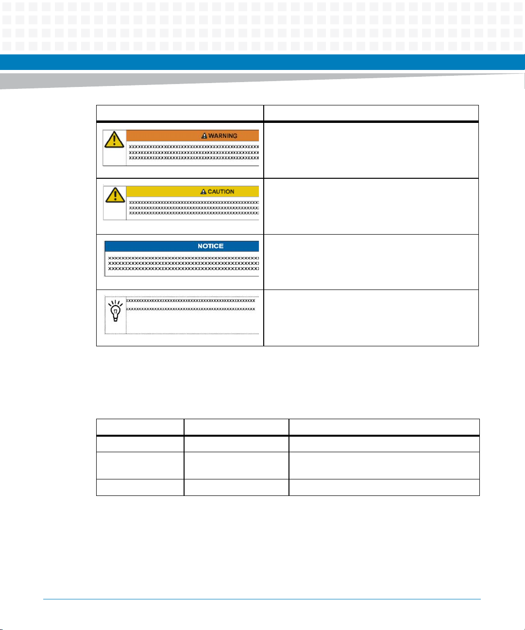
Notation Description
Indicates a hazardous situation which, if not avoided,
could result in death or serious injury
Indicates a hazardous situation which, if not avoided,
may result in minor or moderate injury
Indicates a property damage message
No danger encountered. Pay attention to important
information
About this Manual
Summary of Changes
The table below lists all the revisions implemented in this manual.
Part Number Publication Date Description
6806800M04A September 2011 GA Version
6806800M04B February 2012 Updated Table "COM Express Connector Pinout"
on page 45.
6806800M04C July 2014 Re-branded to Artesyn.
COMX-P1022 COM Express Module Installation and Use (6806800M04C)
15
Page 16

About this Manual
About this Manual
16
COMX-P1022 COM Express Module Installation and Use (6806800M04C)
Page 17

Safety Notes
This section provides warnings that precede potentially dangerous procedures throughout
this manual. Instructions contained in the warnings must be followed during all phases of
operation, service, and repair of this equipment. You should also employ all other safety
precautions necessary for the operation of the equipment in your operating environment.
Failure to comply with these precautions or with specific warnings elsewhere in this manual
could result in personal injury or damage to the equipment.
Artesyn Embedded Technologies intends to provide all necessary information to install and
handle the product in this manual. Because of the complexity of this product and its various
uses, we do not guarantee that the given information is complete. If you need additional
information, ask your Artesyn Embedded Technologies representative.
The product has been designed to meet the standard industrial safety requirements. It must
only be used in its specific area of office telecommunication industry, industrial control, and
development. It must not be used in safety critical components, life supporting devices or on
aircraft.
Only personnel trained by Artesyn Embedded Technologies or persons qualified in electronics
or electrical engineering are authorized to install, remove or maintain the product. The
information given in this manual is meant to complete the knowledge of a specialist and must
not be used as replacement for qualified personnel.
Keep away from live circuits inside the equipment. Operating personnel must not remove
equipment covers. Only factory authorized service personnel or other qualified service
personnel is allowed to remove equipment covers for internal subassembly or component
replacement or any internal adjustment.
This product operates with dangerous voltages that can cause injury or death. Use extreme
caution when handling, testing, and adjusting this equipment and its components.
Operation
Product Damage
High humidity and condensation on surfaces cause short circuits.
Do not operate the product outside the specified environmental limits. Make sure the product
is completely dry and there is no moisture on any surface before applying power.
COMX-P1022 COM Express Module Installation and Use (6806800M04C)
17
Page 18

Safety Notes
Installation
Damage of Circuits
Electrostatic discharge and incorrect installation and removal of the product can damage
circuits or shorten their life.
Before touching the product make sure that your are working in an ESD-safe environment or
wear an ESD wrist strap or ESD shoes. Hold the product by its edges and do not touch any
components or circuits.
Damage of the Product and Additional Devices and Modules
Incorrect installation or removal of additional devices or modules damages the product or the
additional devices or modules.
Before installing or removing additional devices or modules, read the respective
documentation and use appropriate tools.
Pin Damage
Forcing the module into the system may damage the connector pins.
If the module hangs during insertion, pull it out and insert it again.
Environment
Environmental Damage
Improperly disposing of used products may harm the environment.
Always dispose of used products according to your country’s legislation and manufacturer’s
instructions.
18
COMX-P1022 COM Express Module Installation and Use (6806800M04C)
Page 19

Sicherheitshinweise
This section provides a German translation of the Safety Notes.
Dieses Kapitel enthält Hinweise, die potentiell gefährlichen Prozeduren innerhalb dieses
Handbuchs vorrangestellt sind. Beachten Sie unbedingt in allen Phasen des Betriebs, der
Wartung und der Reparatur des Systems die Anweisungen, die diesen Hinweisen enthalten
sind. Sie sollten außerdem alle anderen Vorsichtsmaßnahmen treffen, die für den Betrieb des
Systems innerhalb Ihrer Betriebsumgebung notwendig sind. Wenn Sie diese
Vorsichtsmaßnahmen oder Sicherheitshinweise, die an anderer Stelle diese Handbuchs
enthalten sind, nicht beachten, kann das Verletzungen oder Schäden am System zur Folge
haben.
Artesyn Embedded Technologies ist darauf bedacht, alle notwendigen Informationen zum
Einbau und zum Umgang mit dem System in diesem Handbuch bereit zu stellen. Da es sich
jedoch bei dem System um ein komplexes Produkt mit vielfältigen Einsatzmöglichkeiten
handelt, können wir die Vollständigkeit der im Handbuch enthaltenen Informationen nicht
garantieren. Falls Sie weitere Informationen benötigen sollten, wenden Sie sich bitte an die für
Sie zuständige Geschäftsstelle von Artesyn Embedded Technologies.
Das Produkt erfüllt die für die Industrie geforderten Sicherheitsvorschriften und darf
ausschließlich für Anwendungen in der Telekommunikationsindustrie, im Zusammenhang mit
Industriesteuerungen und in der Entwicklung verwendet werden. Es darf nicht in
sicherheitskritischen Anwendungen, lebenserhaltenden Geräten oder in Flugzeugen
verwendet werden.
Einbau, Wartung und Betrieb dürfen nur von durch Artesyn Embedded Technologies
ausgebildetem oder im Bereich Elektronik oder Elektrotechnik qualifiziertem Personal
durchgeführt werden. Die in diesem Handbuch enthaltenen Informationen dienen
ausschließlich dazu, das Wissen von Fachpersonal zu ergänzen, können dieses jedoch nicht
ersetzen.
Halten Sie sich von stromführenden Leitungen innerhalb des Systems fern. Entfernen Sie auf
keinen Fall die Systemabdeckung. Nur werksseitig zugelassenes Wartungspersonal oder
anderweitig qualifiziertes Wartungspersonal darf die Systemabdeckung entfernen, um
Systemkomponenten zu ersetzen oder andere Anpassungen vorzunehmen.
Installieren Sie keine Ersatzteile oder führen Sie keine unerlaubten Veränderungen am System
durch, sonst verfällt die Garantie. Wenden Sie sich für Wartung oder Reparatur bitte an die für
Sie zuständige Geschäftsstelle von Artesyn Embedded Technologies. So stellen Sie sicher, dass
alle sicherheitsrelevanten Aspekte beachtet werden.
COMX-P1022 COM Express Module Installation and Use (6806800M04C)
19
Page 20

Sicherheitshinweise
Artesyn Embedded Technologies und unsere Zulieferer unternehmen größte Anstrengungen
um sicherzustellen, dass sich Pins und Stecker von Boards vor dem Verlassen der
Produktionsstätte in einwandfreiem Zustand befinden. Verbogene Pins, verursacht durch
fehlerhafte Installation oder durch Installation von Boards mit beschädigten Steckern kann die
durch Artesyn Embedded Technologies gewährte Garantie für Boards und Backplanes
erlöschen lassen.
Dieses Produkt wird mit gefährlichen Spannungen betrieben, die zu Verletzungen und Tod
führen können. Seien Sie im Umgang mit dem Produkt und beim Testen und Anpassen des
Produktes und seiner Komponenten äußerst vorsichtig.
Betrieb
Beschädigung des Systems
Hohe Luftfeuchtigkeit und Kondensat auf den Oberflächen der Produkte kann zu
Kurzschlüssen führen.
Betreiben Sie die Produkte nur innerhalb der angegebenen Grenzwerte für die relative
Luftfeuchtigkeit und Temperatur und stellen Sie vor dem Einschalten des Stroms sicher, dass
sich auf den Produkten kein Kondensat befindet.
System Installation
Beschädigung von Schaltkreisen
Elektrostatische Entladung und unsachgemäßer Ein- und Ausbau des Produktes kann
Schaltkreise beschädigen oder ihre Lebensdauer verkürzen.
Bevor Sie das Produkt oder elektronische Komponenten berühren, vergewissern Sie sich, daß
Sie in einem ESD-geschützten Bereich arbeiten.
Beschädigung des Produktes und der Zusatzmodule
Fehlerhafter Ein- oder Ausbau von Zusatzmodulen führt zu Beschädigung des Produktes oder
der Zusatzmodule.
Lesen Sie deshalb vor dem Ein- oder Ausbau von Zusatzmodulen die Dokumentation und
benutzen Sie angemessenes Werkzeug.
20
COMX-P1022 COM Express Module Installation and Use (6806800M04C)
Page 21

Umweltschutz
Umweltverschmutzung
Falsche Entsorgung der Produkte schadet der Umwelt.
Entsorgen Sie alte Produkte gemäß der in Ihrem Land gültigen Gesetzgebung und den
Empfehlungen des Herstellers.
Sicherheitshinweise
COMX-P1022 COM Express Module Installation and Use (6806800M04C)
21
Page 22

Sicherheitshinweise
22
COMX-P1022 COM Express Module Installation and Use (6806800M04C)
Page 23
Introduction
1.1 Features
COMX-P1022 COM Express Module is a COM Express module based on the Freescale P1022
processor and derivative processors P1013. COM Express is an industry-standard embedded
computer module defined by PICMG.
The following table summarizes the features of COMX-P1022 COM Express Module.
Table 1-1 COMX-P1022 Features Summary
Function Features
Processor Freescale Power PC
Memory Supports 2GB DDR3 667MT/s DDR3+ECC arranged in
Chapter 1
– P1022: 1.066 GHz dual core
– P1013: Single core
two ranks on one slot
SD Card 2 GB MicroSD Card on module
SDHC signals routed to the COM-E connector
Storage for bootloader and OS
UART Two UARTs
Video Supports up to 1280x1024@60 HZ
24bpp display color depth
Supports DVI and LVDS interfaces
Ethernet Broadcom BCM5482 supports two 10/100/1000BASE-T
ports.
USB Four USB2.0 ports routed to the COM-E connector
PCI Express Two x1 PCI-E 1.0 and one x2 PCI-E 1.0 (@2.5 GT/s) ports
routed to the COM-E connectors.
Boot Loader TBD
I2C Four ports
RTC M41ST85WMX6TR
JTAG JTAG connector on module
Audio I2S/SSI interface
SATA Two SATA ports routed to the COM-E connectors
COMX-P1022 COM Express Module Installation and Use (6806800M04C)
23
Page 24

Introduction
1.2 Standard Compliances
This product meets the following standards:
Table 1-2 Standard Compliances
Standard Description
UL/CSA 60950-1
EN 60950-1
IEC 60950-1 CB Scheme
FCC 47 CFR Part 15 Subpart B (US),
Class A
EN55022 Class A (EU)
AS/NZS CISPR 22 Class A
(Australia/New Zealand)
VCCI Class A (Japan)
Legal safety requirements
EMC requirements (legal) on system level (predefined
Artesyn system)
24
COMX-P1022 COM Express Module Installation and Use (6806800M04C)
Page 25
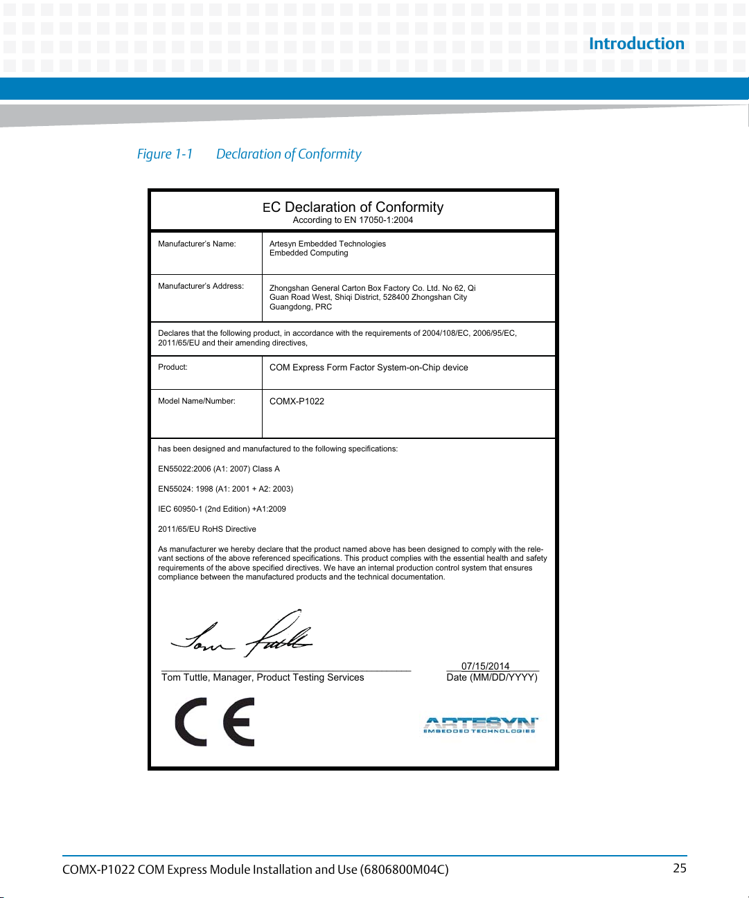
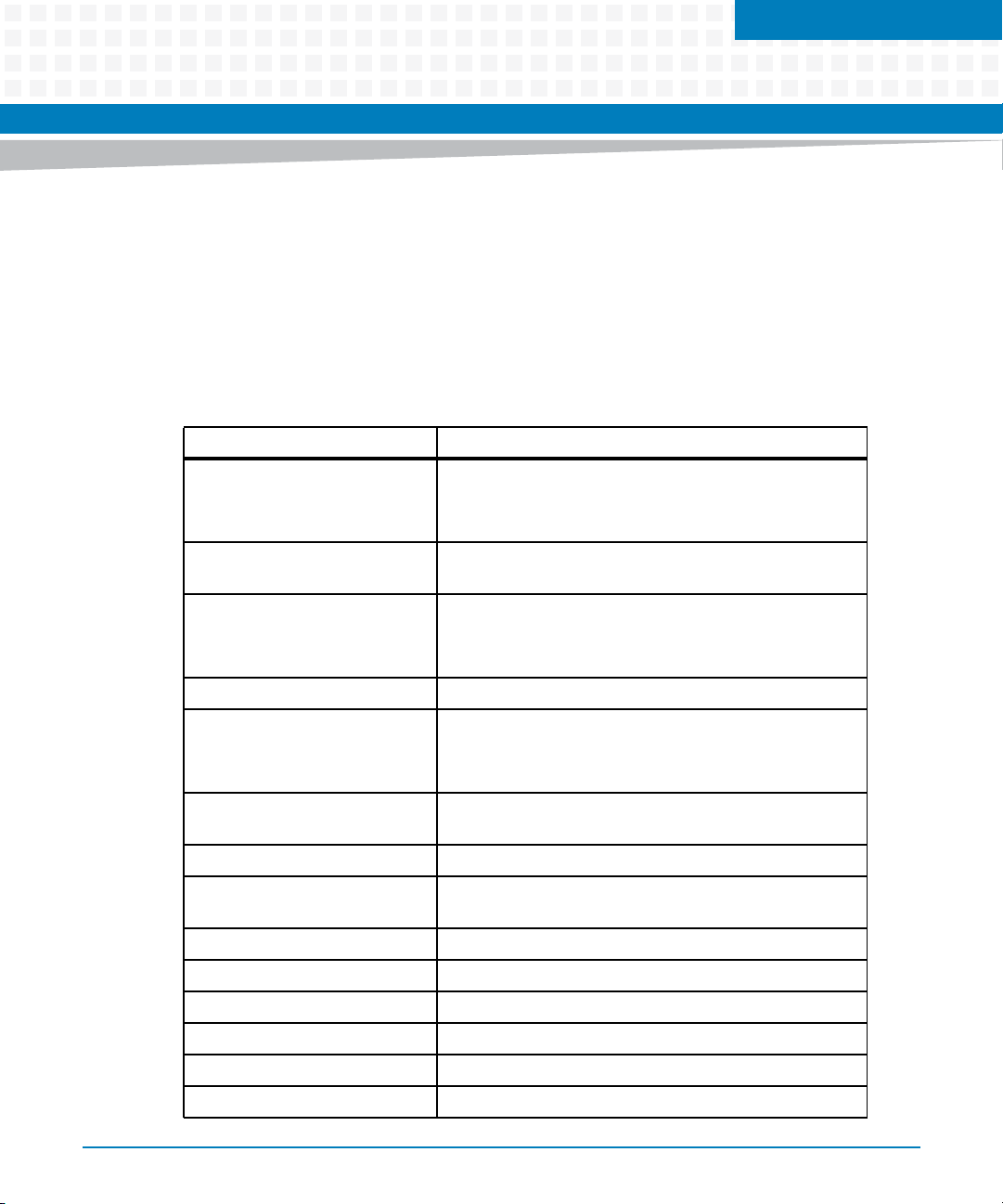
Figure 1-1 Declaration of Conformity
E
C Declaration of Conformity
According to EN 17050-1:2004
Manufacturer’s Name:
Manufacturer’s Address:
Declares that the following product, in accordance with the requirements of 2004/108/EC, 2006/95/EC,
2011/65/EU and their amending directives,
Product:
Artesyn Embedded Technologies
Embedded Computing
Zhongshan General Carton Box Factory Co. Ltd. No 62, Qi
Guan Road West, Shiqi District, 528400 Zhongshan City
Guangdong, PRC
COM Express Form Factor System-on-Chip device
Introduction
Model Name/Number:
has been designed and manufactured to the following specifications:
EN55022:2006 (A1: 2007) Class A
EN55024: 1998 (A1: 2001 + A2: 2003)
IEC 60950-1 (2nd Edition) +A1:2009
2011/65/EU RoHS Directive
As manufacturer we hereby declare that the product named above has been designed to comply with the rele-
vant sections of the above referenced specifications. This product complies with the essential health and safety
requirements of the above specified directives. We have an internal production control system that ensures
compliance between the manufactured products and the technical documentation.
___________________________________________________ ___07/15/2014______
COMX-P1022
Tom Tuttle, Manager, Product Testing Services Date (MM/DD/YYYY)
COMX-P1022 COM Express Module Installation and Use (6806800M04C)
25
Page 26
Introduction
1.3 Mechanical Data
1.3.1 COMX-P1022 Mechanical Data
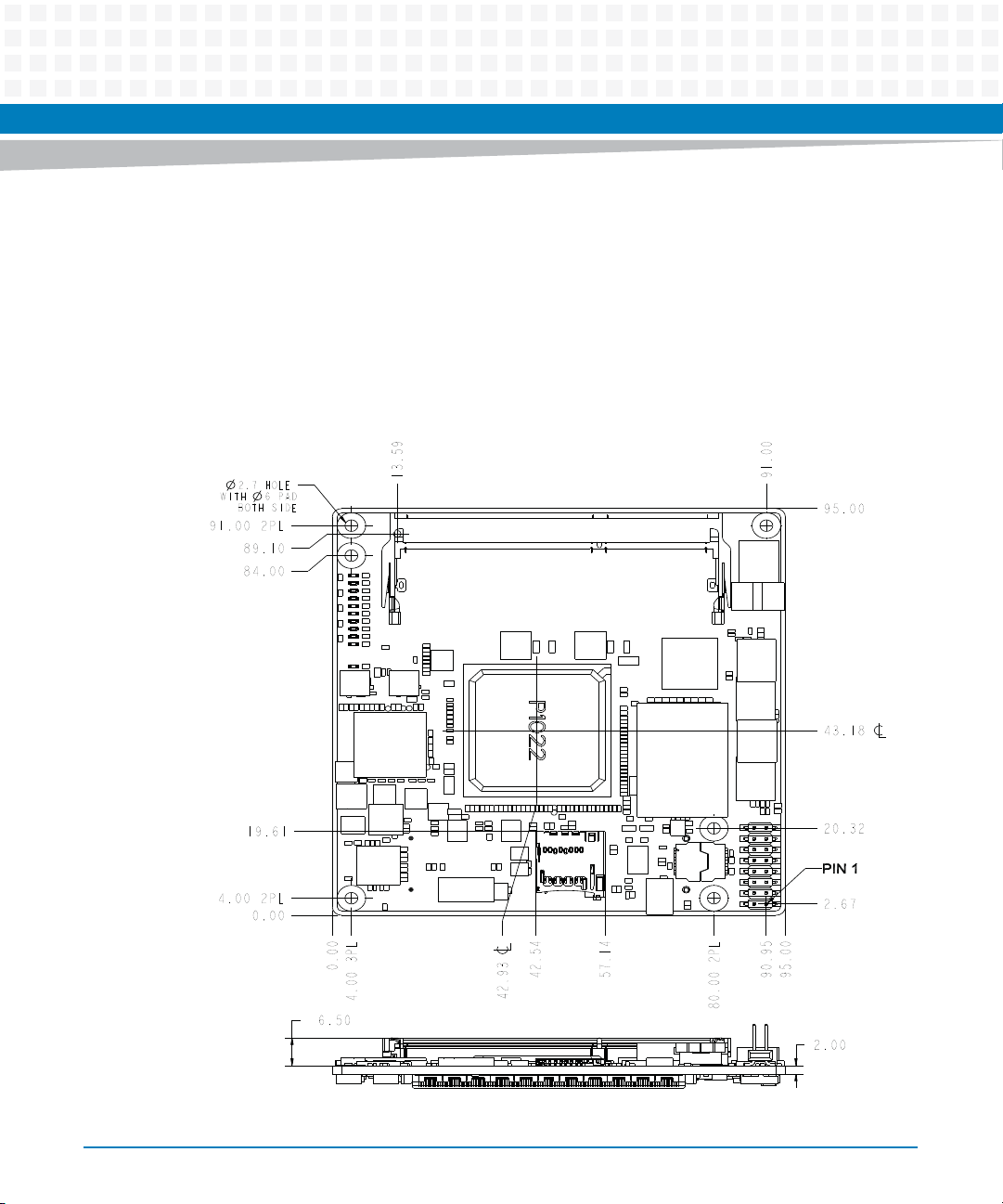
Figure 1-2 COMX-P1022 Mechanical Dimensions (Top and Side View)
2.7 HOLE
WITH 6 PAD
BOTH SIDE
2PL91.00
89.10
84.00
19.61
2PL4.00
0.00
6.50
0.00
3PL4.00
13.59
42.93
42.54
57.14
2PL80.00
91.00
90.95
95.00
95.00
43.18
20.32
PIN 1
2.67
2.00
26
COMX-P1022 COM Express Module Installation and Use (6806800M04C)
Page 27

Table 1-3 Mechanical Data
Feature Value
Dimensions COM Express basic form factor: 95 mm x 95 mm
Weight 70.0 g
Introduction
COMX-P1022 COM Express Module Installation and Use (6806800M04C)
27
Page 28

Introduction
1.3.2 Heat Spreader Mechanical Data
Figure 1-3 Heat Spreader Mechanical Dimensions (Front and Side View)
95.00
10.00
30.50
20.00
11.50
95.00
28
11.00
COMX-P1022 COM Express Module Installation and Use (6806800M04C)
Page 29

1.3.3 Cooler Mechanical Data
Figure 1-4 Cooler Mechanical Dimensions (Front and Side View)
Introduction
95.00
10.00
30.50
20.00
11.50
95.00
COMX-P1022 COM Express Module Installation and Use (6806800M04C)
23.50
29
Page 30

Introduction
1.4 Board Identification
This section shows the serial number and its location on the board.
Figure 1-5 Serial Number Location
Serial Number
1.5 Ordering Information
1.5.1 Supported Board Models
The following table lists the product variants that are available upon release of this publication.
Table 1-4 Available Board Variants
Order Number Description
COMX-P1022 P1022 COM Module
30
COMX-P1022 COM Express Module Installation and Use (6806800M04C)
Page 31

Table 1-4 Available Board Variants (continued)
Order Number Description
COMX-P1022-2G-KIT P1022 COM Module with 2 GB memory and heatsink
For availability of other variants, consult your local Artesyn sales representative.
1.5.2 Board Accessories
The following table lists the board accessories that are available upon release of this
publication.
Table 1-5 Available Board Accessories
Order Number Description
COMX-P1022-HSP Heat spreading plate
Introduction
COMX-P1022-HTSNK Heatsink
For availability of other board accessories, consult your local Artesyn sales representative.
COMX-P1022 COM Express Module Installation and Use (6806800M04C)
31
Page 32

Introduction
32
COMX-P1022 COM Express Module Installation and Use (6806800M04C)
Page 33

Hardware Preparation and Installation
2.1 Environmental and Power Requirements
2.1.1 Environmental Requirements
The following table lists the environmental requirements that the board must meet when
operated in your particular system configuration.
Operating temperatures refer to the temperature of the air circulating around the board and
not to the component temperature.
Chapter 2
Product Damage
High humidity and condensation on surfaces cause short circuits.
Do not operate the system outside the specified environmental limits. Make sure the
product is completely dry and there is no moisture on any surface before applying power.
Table 2-1 Environmental Requirements
Requirement Operating Non-Operating
Temp Cycle Class -40°C to 85°C:500 cycles
Temperature 0°C to 60°C -40°C to 85°C
Humidity 10% to90% (non-condensing)
Vibration 0.01g2/Hz @ 5-500Hz (Random Vibration)
Shock 20G peak 11ms (half sine)
Altitude -60 to 4000m ASL
COMX-P1022 COM Express Module Installation and Use (6806800M04C)
33
Page 34

Hardware Preparation and Installation
2.1.2 Thermal Requirements
Table 2-2 Critical Temperature Spots for COMX-P1022
Heat Dissipation Power
Component Identifier
CPU-P1022 6 Tjmax = 125
SODIMM Tcmax = 85
(W)
Maximum Allowable
Temperature (°C)
Contact your Artesyn sales representative for current information on the detailed thermal
information including airflow and resistance of the module.
System Overheating
Cooling Vents
Improper cooling can lead to system damage and can void the manufacturer's warranty.
To ensure proper cooling and undisturbed airflow through the system do not obstruct the
ventilation openings of the system. Make sure that the fresh air supply is not mixed with hot
exhaust from other devices.
34
Personal Injury
During operation, hot surfaces may be present on the heat sinks and the components of the
product.
To prevent injury from hot surface do not touch any of the exposed components or
heatsinks on the product when handing. Use the handle and face plate, where applicable, or
the board edge when removing the product from the enclosure.
COMX-P1022 COM Express Module Installation and Use (6806800M04C)
Page 35

2.1.3 Power Requirements
Table 2-3 Board Power Supply Current Requirements
0.75V 1.0V 1.2V 1.5V 1.8V 2.5V 3.3V
CPU(P1022) 6000 1000 100 200
DDR3 600 4400
USB PHY(3315) 55
USB HUB(2514) 415
GE PHY BCM5482 260 88
DS90C385 493
TFP410PAP 250
Hardware Preparation and Installation
74LVCH32244A x2 120
Total 23.17W 0.45W 6W 3.12W 8.1W 0.5W 5W
2.2 Unpacking and Inspecting the Module
Damage of Circuits
Electrostatic discharge and incorrect installation and removal of the product can damage
circuits or shorten its life.
Before touching the product make sure that you are working in an ESD-safe environment or
wear an ESD wrist strap or ESD shoes. Hold the product by its edges and do not touch any
components or circuits.
COMX-P1022 COM Express Module Installation and Use (6806800M04C)
35
Page 36

Hardware Preparation and Installation
Shipment Inspection
1. Verify that you have received all items of your shipment:
Printed Quick Start Guide and Safety Notes
COMX-P1022 COM Express Module
2. Check for damage and report any damage or differences to customer service.
3. Remove the desiccant bag shipped together with the product.
Environmental Damage
Improperly disposing of used products may harm the environment.
Always dispose of used products according to your country’s legislation and manufacturer’s
instructions.
2.3 Preparing the Installation Environment
Before you install or replace components, pay attention to the following:
Wear an ESD-preventive wrist strap to prevent the static electricity from damaging the
device.
Keep the area where the components reside clean and keep the components away from
heat-generating devices, such as radiator.
Ensure that your sleeves are tightened or rolled up above the elbow. For safety purposes,
it is not recommended to wear jewelry, watch, glasses with metal frame, or clothes with
metal buttons.
Do not exert too much force, or insert or remove the components forcibly. Avoid damage
to the components or plug-ins.
36
COMX-P1022 COM Express Module Installation and Use (6806800M04C)
Page 37

Hardware Preparation and Installation
Confirm the feasibility of the operation
There are available spare parts of the components to be installed or replaced in the
equipment warehouse. When the available spare parts are lacking, contact Artesyn
Embedded Technologies for help in time. For details on how to get help from Artesyn
Embedded Technologies, visit http://www.artesyn.com/computing/.
Make sure that the new components are in good condition, without defects such as
oxidation, chemical corrosion, missing components, or transportation damage.
By reading this document, you are familiar with how to install and replace the component
and master the skills required by the operation.
Check the environment
Make sure that the power supply, temperature, and humidity meet the operating
requirements for the board and its components. For details, refer to the respective system
documentation.
Prepare the parts and the tools
Prepare the components to be installed or replaced.
When you hold or transport the components, use the special antistatic package. Prepare
the cross screwdriver, screws, plastic supports, cooling gel, and ESD-preventive wrist
strap.
Confirm installation or changing position
Confirm the position where COMX-P1022 COM Express Module will be installed.
If a serious problem occurs and cannot be solved when you install or replace the
component, contact Artesyn for technical support.
2.4 Installing and Removing the Memory Module
There is one 204-pin SODIMM slot on the COMX-P1022 COM Express Module.
Pin Damage
Forcing the module into the system may damage connector pins.
If the module hangs during insertion, pull it out and insert it again.
COMX-P1022 COM Express Module Installation and Use (6806800M04C)
37
Page 38

Hardware Preparation and Installation
Installing a Memory Module
1. Wear the ESD-preventive wrist strap.
2. Lay the COM-E module where the SODIMM is to be installed on the anti-static
desktop.
3. Take the SODIMM out of the anti-static package, holding it by the edges.
4. Line up the notch located on the row of the metal pins at the bottom of the module
with the key in the SODIMM slot on the COM-E module.
5. Insert the SODIMM in a slantwise position or at a 45-degree angle to slide the
memory module into place.
38
COMX-P1022 COM Express Module Installation and Use (6806800M04C)
Page 39

Hardware Preparation and Installation
6. Press down on the memory module against the COM-E module until you hear it
snap into place. The module must be properly aligned before you press it down into
its final position. You can remove the module from the socket and reinstall it if you
cannot press it down into its final position.
Removing a Memory Module
1. Wear the ESD-preventive wrist strap.
2. Release the module from the slot by pushing the spring latches on either side of the
module outward.
3. Lift the module from the COM-E Module.
Damage of the Product and Additional Devices and Modules
Incorrect installation or removal of additional devices or modules damages the product or
the additional devices or modules.
Before installing or removing additional devices or modules, read the respective
documentation and use appropriate tools.
COMX-P1022 COM Express Module Installation and Use (6806800M04C)
39
Page 40

Hardware Preparation and Installation
2.5 Installing the MicroSD Card
COMX-P1022 COM Express Module has an on-module MicroSD card slot with a 2 GB MicroSD
card installed.
Figure 2-1 MicroSD Card Slot
40
Installing the MicroSD Card
1. Insert the MicroSD card to the MicroSD socket.
2. Make sure that the metallic contact point of the MicroSD card and the MicroSD
socket are lined up correctly.
COMX-P1022 COM Express Module Installation and Use (6806800M04C)
Page 41

Hardware Preparation and Installation
2.6 Installing and Removing the Heat Spreader/Cooler
Installing the Heat Spreader/Cooler
1. Check the thermal interface material pads on the heat spreader/cooler. Make sure
the pads are aligned to their corresponding components on the COMX-P1022 COM
Express module.
2. Align the standoffs of the heat spreader/cooler with the screw holes on the COMX-
P1022 COM Express module.
3. Hold the heat spreader/cooler and COMX-P1022 COM Express module.
4. From the backside of COMX-P1022 COM Express module, use two screws to fasten
the module to the heat spreader/cooler through two internal mounting holes.
Removing the Heat Spreader/Cooler
1. Loosen and remove the two pieces of screws that attach the heat spreader/cooler
to the COMX-P1022 COM Express module.
2. While holding the edges, pull the heat spreader/cooler from the COMX-P1022 COM
Express module.
2.7 Installing and Removing the Module on the Carrier Board
The assembled COM Express module with the attached heat spreader/ cooler is attached to a
carrier board.
COMX-P1022 COM Express Module Installation and Use (6806800M04C)
41
Page 42

Hardware Preparation and Installation
Installing the COM Express Module on the Carrier Board
1. Line up the board-to-board connector of the COMX-P1022 COM Express Module
assembly with the board-to-board connector of the carrier board.
2. Make sure that the interconnectors are properly aligned and that the bottom
surface of the COMX-P1022 COM Express Module have contact with the four
standoffs on carrier board.
3. From the topside of the COMX-P1022 COM Express Module assembly, locate the
screw holes on heat spreader/cooler.
4. Use the screws to fasten the COMX-P1022 COM Express Module assembly to the
carrier board.
Removing the COM Express Module from the Carrier Board
1. From the topside of the COMX-P1022 COM Express Module assembly, locate the
four screws that connect the COMX-P1022 COM Express Module assembly to the
carrier board.
2. Loosen and remove the screws.
3. While holding the edges, pull the COMX-P1022 COM Express Module from the
carrier board.
42
COMX-P1022 COM Express Module Installation and Use (6806800M04C)
Page 43

Controls, LEDs, and Connectors
3.1 Board Layout
Figure 3-1 COMX-P1022 COM Express Module Components
Chapter 3
COMX-P1022 COM Express Module Installation and Use (6806800M04C)
43
Page 44

Controls, LEDs, and Connectors
Figure 3-2 COMX-P1022 COM Express Module Components (Rear View)
3.2 Connectors and Switches
3.2.1 COM Express Connector
The following two tables provide the pin out for the Freescale type COM-E module.
44
COMX-P1022 COM Express Module Installation and Use (6806800M04C)
Page 45

Controls, LEDs, and Connectors
The first column shows the default signal names while the succeeding columns show the
differences in values.
Table 3-1 COM Express Connector Pinout
Row A Row B Row C Row D
A1 GND B1 GND C1 GND (FIXED) D1 GND (FIXED)
A2 GBE0_MDI3- B2 GBE0_ACT# C2 GBE1_ACT# D2 GBE2_ACT#
A3 GBE0_MDI3+ B3 1588_CLK_OUT C3 GBE1_MDI3- D3 GBE2_MDI3-
A4 GBE0_LINK100#B4 1588_PULSE_OUT1C4 GBE1_MDI3+ D4 GBE2_MDI3+
A5 GBE0_LINK1000#B5 1588_PULSE_OUT2C5 GBE1_LINK100# D5 GBE2_LINK100
#
A6 GBE0_MDI2- B6 1588_ALARM_OUT1C6 GBE1_MDI2- D6 GBE2_MDI2-
A7 GBE0_MDI2+ B7 1588_ALARM_OUT2C7 GBE1_MDI2+ D7 GBE2_MDI2+
A8 GBE0_LINK# B8 1588_TRIG_IN1 C8 GBE1_LINK1000# D8 GBE2_LINK100
0#
A9 GBE0_MDI1- B9 1588_TRIG_IN2 C9 GBE1_MDI1- D9 GBE2_MDI1-
A10 GBE0_MDI1+ B10 1588_CLK_IN C10 GBE1_MDI1+ D10 GBE2_MDI1+
A11 GND B11 GND C11 GND (FIXED) D11 GND (FIXED)
A12 GBE0_MDI0- B12 PWRBTN# C12 GBE1_MDI0- D12 GBE2_MDI0-
A13 GBE0_MDI0+ B13 SMB_CK C13 GBE1_MDI0+ D13 GBE2_MDI0+
A14 GBE0_CTREF B14 SMB_DAT C14 GBE1_LINK# D14 GBE2_LINK#
A15 SUS_S3# B15 SMB_ALERT# C15 DDI1_PAIR6+/RSV
D/User Display
A16 SATA0_TX+ B16 SATA1_TX+ C16 DDI1_PAIR6-
/RSVD/User
Display
A17 SATA0_TX- B17 SATA1_TX- C17 CE_PB12/LGPL0 D17 CE_PA0/LCLK0
A18 SUS_S4# B18 SUS_STAT# C18 CE_PB13/LGPL1 D18 CE_PA1/LCLK1
A19 SATA0_RX+ B19 SATA1_RX+ C19 NC D19 NC
D15 IRQ_OUT_B
D16 IRQ_IN0
COMX-P1022 COM Express Module Installation and Use (6806800M04C)
45
Page 46

Controls, LEDs, and Connectors
Table 3-1 COM Express Connector Pinout (continued)
Row A Row B Row C Row D
A20 SATA0_RX- B20 SATA1_RX- C20 NC D20 NC
A21 GND B21 GND C21 GND D21 GND
A22 SATA2_TX+ B22 SATA3_TX+ C22 NC D22 NC
A23 SATA2_TX- B23 SATA3_TX- C23 NC D23 NC
A24 SUS_S5# B24 PWR_OK C24 DDI1_HPD/RSVD/
User Display
A25 SATA2_RX+ B25 SATA3_RX+ C25 DDI1_PAIR4+/RSV
D/User Display
A26 SATA2_RX- B26 SATA3_RX- C26 DDI1_PAIR4-
/RSVD/User
Display
A27 BATLOW# B27 WDT C27 DDI1_AUX+/RSVD
/User Display
A28 (S)ATA_ACT# B28 AC/HAD_SDIN2 C28 DDI1_AUX-
/RSVD/User
Display
A29 AC/HAD_SYNC B29 AC/HAD_SIN1 C29 DDI1_PAIR5+/RSV
D/User Display
A30 AC/HAD_RST# B30 AC/HAD_SIN0 C30 DDI1_PAIR5-
/RSVD/User
Display
A31 GND B31 GND C31 GND D31 GND
A32 AC/HAD_BITCLKB32 SPKR C32 U0_TXD D32 DDI1_PAIR2+/R
D24 CE_PA2/LCS0_B
D25 CE_PA3/LCS1_B
D26 DDI1_PAIR0+/R
SVD/User
Display
D27 DDI1_PAIR0-
/RSVD/User
Display
D28 CE_PB18/LAD0
0
D29 DDI1_PAIR1+/R
SVD/User
Display
D30 DDI1_PAIR1-
/RSVD/User
Display
SVD/User
Display
A33 AC/HAD_SDOUTB33 I2C_CK C33 U0_RXD D33 DDI1_PAIR2-
/RSVD/User
Display
A34 BIOS_DIS0# B34 I2C_DAT C34 U0_CTS D34 CE_PB19/LAD0
1
46
COMX-P1022 COM Express Module Installation and Use (6806800M04C)
Page 47

Controls, LEDs, and Connectors
Table 3-1 COM Express Connector Pinout (continued)
Row A Row B Row C Row D
A35 THERMTRIP# B35 THRM# C35 U0_RTS D35 CE_PB20/LAD0
2
A36 USB6- B36 USB7- C36 U1_TXD D36 DDI1_PAIR3+/R
SVD/User
Display
A37 USB6+ B37 USB7+ C37 U1_RXD D37 DDI1_PAIR3-
/RSVD/User
Display
A38 USB_6_7_OC# B38 USB_4_5_OC# C38 U1_CTS D38 TDM_CLK_Tx0/
SSI_TCK0/User
Defined
A39 USB4- B39 USB5- C39 U1_RTS D39 TDM_CLK_Rx0/
SSI_RCK0/User
Defined
A40 USB4+ B40 USB5+ C40 MDIO1 (clause 22) D40 TDM_TxD0/SSI
_TXD0/User
Defined
A41 GND B41 GND C41 GND D41 GND
A42 USB2- B42 USB3- C42 U2_TXD/User
Defined
A43 USB2+ B43 USB3+ C43 U2_RXD/User
Defined
A44 USB_2_3_OC# B44 USB_0_1_OC# C44 U2_CTS/User
Defined
A45 USB0- B45 USB1- C45 U2_RTS/User
Defined
A46 USB0+ B46 USB1+ C46 U3_TXD/User
Defined
D42 TDM_RxD0/SSI
_RXD0/User
Defined
D43 TDM_TxFS0/SSI
_TFS0/User
Defined
D44 TDM_RxFS0/SSI
_RFS0/User
Defined
D45 SSI_TCK1/TDM
_CLK_Tx1/User
Defined
D46 SSI_RCK1/TDM
_CLK_Rx1/User
Defined
COMX-P1022 COM Express Module Installation and Use (6806800M04C)
47
Page 48

Controls, LEDs, and Connectors
Table 3-1 COM Express Connector Pinout (continued)
Row A Row B Row C Row D
A47 VCC_RTC B47 EXCD1_PERST# C47 U3_RXD/User
Defined
D47 SSI_TXD1/TDM
_TxD1/User
Defined
A48 EXCD0_PERST# B48 EXCD1_CPPE# C48 U3_CTS/User
Defined
A49 EXCD0_CPPE# B49 SYS_RESET# C49 U3_RTS/User
Defined
A50 LPC_SERIRQ B50 CB_RESET# C50 MDC1 (clause 22) D50 SSI_RFS1/TDM_
A51 GND B51 GND C51 GND D51 GND
A52 NC B52 NC C52 SERDES_RX16+ D52 SERDES_TX16+
A53 NC B53 NC C53 SERDES_RX16- D53 SERDES_TX16-
A54 SD_DATA0 B54 SD_CMD C54 TYPE0# D54 TYPE3#
A55 SERDES_TX4+ B55 SERDES_RX4+ C55 SERDES_RX17+ D55 SERDES_TX17+
A56 SERDES_TX4- B56 SERDES_TX4- C56 SERDES_RX17- D56 SERDES_TX17-
A57 GND B57 SD_WP C57 TYPE1# D57 TYPE2#
A58 NC B58 NC C58 NC D58 NC
A59 NC B59 NC C59 NC D59 NC
A60 GND B60 GND C60 GND D60 GND (FIXED)
A61 NC B61 NC C61 NC D61 NC
D48 SSI_RXD1/TDM
_RxD1/User
Defined
D49 SSI_TFS1/TDM_
TxFS1/User
Defined
RxFS1/User
Defined
A62 NC B62 NC C62 NC D62 NC
A63 SD_DATA1 B63 SD_CD# C63 MDIO2 (clause 22
or 45)
A64 NC B64 NC C64 GND D64 LP_TAMPER_DE
A65 NC B65 NC C65 NC D65 NC
A66 GND B66 WAKE0# C66 NC D66 NC
A67 SD_DATA2 B67 WAKE1# C67 CE_PA12 / LAD00 D67 GND
48
COMX-P1022 COM Express Module Installation and Use (6806800M04C)
D63 MDC2 (Clause
45)
T_BAT
Page 49

Controls, LEDs, and Connectors
Table 3-1 COM Express Connector Pinout (continued)
Row A Row B Row C Row D
A68 SERDES_TX0+ B68 SERDES_RX0+ C68 NC D68 NC
A69 SERDES_TX0- B69 SERDES_RX0- C69 NC D69 NC
A70 GND B70 GND C70 GND (FIXED) D70 GND (FIXED)
A71 LVDS_A0+ B71 LVDS_B0+ C71 NC D71 NC
A72 LVDS_A0- B72 LVDS_B0- C72 NC D72 NC
A73 LVDS_A1+ B73 LVDS_B1+ C73 DDI1_CTRLDATA/
RSVD/User
Display
A74 LVDS_A1- B74 LVDS_B1- C74 NC D74 NC
A75 LVDS_A2+ B75 LVDS_B2+ C75 NC D75 NC
A76 LVDS_A2- B76 LVDS_B2- C76 GND D76 GND
A77 LVDS_VDD_EN B77 LVDS_B3+ C77 CE_PA13 / LGPL2 D77 CE_PA14 /
A78 LVDS_A3+ B78 LVDS_B3- C78 NC D78 NC
A79 LVDS_A3- B79 LVDS_BKLT_EN C79 NC D79 NC
A80 GND B80 GND C80 GND (FIXED) D80 GND
A81 LVDS_A_CK+ B81 LVDS_B_CK+ C81 CE_PA15 / LGPL3 D81 CE_PA20
A82 LVDS_A_CK- B82 LVDS_B_CK- C82 CE_PA16 / LGPL4 D82 CE_PA21
A83 LVDS_I2C_CK B83 LVDS_BKLT_CTRL C83 IRQ01 D83 CE_PA18
A84 LVDS_I2C_DAT B84 VCC_5V_SBY C84 GND D84 GND
A85 SD_DATA3 B85 VCC_5V_SBY C85 IRQ02 D85 CE_PA19
A86 KBD_RST# B86 VCC_5V_SBY C86 CE_PA17 /
IRQ_IN3
A87 KBD_A20GATE B87 VCC_5V_SBY C87 GND D87 GND
D73 DDI1_CTRLCLK/
RSVD/User
Display
LWE0_B
D86 CE_PA24
A88 SERDES_CK_REF+B88 SPI_CS1# C88 CE_PA25 / GPI0 D88 CE_PA29 /
GPO0
A89 SERDES_CK_REF-B89 VGA_RED C89 CE_PA26 / GPI1 D89 CE_PA30 /
GPO1
A90 GND B90 GND C90 GND (FIXED) D90 GND
COMX-P1022 COM Express Module Installation and Use (6806800M04C)
49
Page 50

Controls, LEDs, and Connectors
Table 3-1 COM Express Connector Pinout (continued)
Row A Row B Row C Row D
A91 SPI_CS0# B91 VGA_GRN C91 CE_PA27 / GPI2 D91 CE_PA31 /
GPO2
A92 SPI_MISO B92 VGA_BLU C92 CE_PA28 / GPI3 D92 CE_PB0
A93 SD_CLK B93 VGA_HSYNC C93 GND D93 GND
A94 SPI_CLK B94 VGA_VSYNC C94 CE_PB1 D94 CE_PB8
A95 SPI_MOSI B95 VGA_I2C_CK C95 CE_PB2 D95 CE_PB9
A96 GND B96 VGA_I2C_DAT C96 GND D96 GND
A97 VCC_12V B97 CE_PB31 C97 CE_PB3 D97 CE_PB21
A98 VCC_12V B98 CE_PA22 C98 SPI_CS2# D98 CE_PB22
A99 VCC_12V B99 CE_PA23 C99 SPI_CS3# D99 CE_PB23
A100 GND B100 GND C100 GND (FIXED) D100 GND (FIXED)
A101 VCC_12V B101 VCC_12V C101 SGMII_CLK+ D101 CE_PB29
A102 VCC_12V B102 VCC_12V C102 SGMII_CLK- D102 CE_PB30
A103 VCC_12V B103 VCC_12V C103 GND D103 GND
A104 VCC_12V B104 VCC_12V C104 VCC_12V D104 VCC_12V
A105 VCC_12V B105 VCC_12V C105 VCC_12V D105 VCC_12V
A106 VCC_12V B106 VCC_12V C106 VCC_12V D106 VCC_12V
A107 VCC_12V B107 VCC_12V C107 VCC_12V D107 VCC_12V
A108 VCC_12V B108 VCC_12V C108 VCC_12V D108 VCC_12V
A109 VCC_12V B109 VCC_12V C109 VCC_12V D109 VCC_12V
A110 GND B110 GND C110 GND D110 GND
50
COMX-P1022 COM Express Module Installation and Use (6806800M04C)
Page 51

3.2.2 Default Switch Settings
Switches that are not mentioned should always be switched OFF.
3.2.2.1 DIP Switch Setting
Table 3-2 Configure I2CMUX
S1_23 Description
Controls, LEDs, and Connectors
OFF SPI ON MODULE
ON SPI ON CARRIER
3.2.2.2 Boot Location Configuration
Table 3-3 Boot Location Configuration
S4_14 S4_23 S5_14 S5_23 Description
ON ON ON ON BOOT FROM PCIE 1
ON ON ON OFF BOOT FROM PCIE 2
ON ON OFF ON RESERVED
ON ON OFF OFF RESERVED
ON OFF ON ON BOOT FROM DDR
ON OFF ON OFF BOOT FROM PCIE 3
ON OFF OFF ON BOOT FROM SPI
ON OFF OFF OFF *BOOT FROM SDHC
COMX-P1022 COM Express Module Installation and Use (6806800M04C)
51
Page 52

Controls, LEDs, and Connectors
Table 3-3 Boot Location Configuration (continued)
S4_14 S4_23 S5_14 S5_23 Description
OFF ON ON ON BOOT FROM 8BIT
OFF ON ON OFF RESERVED
OFF ON OFF ON BOOT FROM 8BIT
OFF ON OFF OFF RESERVED
OFF OFF ON ON BOOT FROM 16BIT NOR
OFF OFF ON OFF BOOT FROM 8BIT NOR
OFF OFF OFF ON BOOT FROM 16BIT NOR
NANDFLASH SMALL PAGE
NANDFLASH LARGE PAGE
FLASH
FLASH
FLASH
OFF OFF OFF OFF BOOT FROM 16BIT NOR
3.2.2.3 SPI CS0 Configuration
Table 3-4 SPI CS0 Configuration
S1_23 Description
OFF SPI ON MODULE
ON SPI ON CARRIER
FLASH
52
COMX-P1022 COM Express Module Installation and Use (6806800M04C)
Page 53

Controls, LEDs, and Connectors
3.2.2.4 SDHC Write-protect
Table 3-5 SDHC Write-protect
S3_14 SDHC WP ON CARRIER S3_23 SDHC WP ON MODULE
OFF Write protect OFF Write protect
ON Write ON Write
3.2.3 System Status LEDs
LEDs indicate the status of the power and the CPU before any software is run.
Table 3-6 System LED Status
Location Status
D1 CPU Core Power OK(1.0V)
D2 DDR3 Power OK(1.5V)
D3 3.3V Power OK
D4 2.5V Power OK
D5 1.2V Power OK
D6 1.8V Power OK
D9 CPU in Sleep state
D10 1.0V_SW Power OK
D11 1.0V_SW_IO Power OK
D12 3.3V_SW Power OK
D13 2.5V_SW Power OK
COMX-P1022 COM Express Module Installation and Use (6806800M04C)
53
Page 54

Controls, LEDs, and Connectors
3.2.4 JTAG
COMX-P1022 supports JTAG method for CPU and GE PHY debugging.
Table 3-7 CPU Debug (P1)
Pin Signal Pin Signal
1 JTAG_TDO 2 NC
3 JTAG_TDI 4 COP_TRST#
5 COP_RUNSTOP 6 COP_VSENSE
7 JTAG_TCK 8 P_CKSTP_IN#
9 JTAG_TMS 10 NC
11 COP_SRST# 12 GND
13 COP_HRST# 14 NC
15 P_CKSTP_OUT# 16 GND
Table 3-8 GE PHY Debug (Test Point14-19)
Test Point Signal
TP2 JTAG_GE_TDI
TP3 JTAG_GE_TDO
TP4 JTAG_GE_TCK
TP5 JTAG_GE_TMS
TP6 JTAG_GE_TRST#
3.2.5 GPIO
Table 3-9 GPIO Description
GPIO FUNCTION
TRIG_OUT /GPIO3_21 SATA_ACT#
54
COMX-P1022 COM Express Module Installation and Use (6806800M04C)
Page 55

Table 3-9 GPIO Description (continued)
GPIO FUNCTION
IRQ11/ GPIO3_13 WATCHDOG
TRIG_IN/GPIO3_20 LVDS_ENABLE
UDE1_B/GPIO3_17 LVDS_ENAVDD
POWER_OK/GPIO3_19 LVDS_PWM
IRQ6/GPIO2_31 MUX_I2C
IRQ7/ GPIO3_9 GPI0
IRQ8/ GPIO3_10 GPI1
IRQ9/ GPIO3_11 GPI2
IRQ10/ GPIO3_12 GPI3
MCP0_B/GPIO3_14 GPO0
MCP1_B/GPIO3_15 GPO1
Controls, LEDs, and Connectors
UDE0_B/GPIO3_16 GPO2
READY_P1/GPIO3_22 GPO3
COMX-P1022 COM Express Module Installation and Use (6806800M04C)
55
Page 56

Controls, LEDs, and Connectors
56
COMX-P1022 COM Express Module Installation and Use (6806800M04C)
Page 57

Functional Description
4.1 Block Diagram
Figure 4-1 Block Diagram
Chapter 4
4.2 Processor
COMX-P1022 COM Express Module supports the Freescale P1022 processor and compatible
with the P1013 processor. P1022 includes the following features:
Dual e500v2 Core, 533MHz to 1.066 GHz clock frequency
Power consumption of less than 6 W at 1.066 GHz
COMX-P1022 COM Express Module Installation and Use (6806800M04C)
57
Page 58

Functional Description
32 KB instruction and 32 KB data first-level cache (L1) for each core
256 KB second-level cache (L2) with ECC
64 bit DDR2/DDR3 controller with ECC supports data rate of up to 667 Mbps per pin
31x31 mm 689-pin wirebond power-BGA
45 nm SOI process technology
Each e500 core complex contains a separate 32-KB, eight-way set associative level 1 (L1)
instruction and data caches to provide the execution units and registers rapid access to
instructions and data. The 32 KB cache is divided into eight ways and 128 sets, so there is a
total of 1024 blocks. The size of each block is eight words (32 bytes).
Figure 4-2 P1022 Processor Block Diagram
4.3 Memory
P1022 supports 64-bit DDR2/DDR3 SDRAM memory controller with ECC.
The COM-E module supports a 2GB dual-rank DDR3 with ECC SO-UDIMM memory modules
which can be run at 667MHz.
58
COMX-P1022 COM Express Module Installation and Use (6806800M04C)
Page 59

4.3.1 SDRAM
COMX-P1022 COM Express Module only supports 2 GB DDR3 667 MT/s DDR3+ECC arranged in
two ranks in one slot.
4.3.2 SD Card
COMX-P1022 COM Express Module has a microSD card slot on-module with a 2 GB SD card
installed. The SD card stores the Bootloader and the Operating System.
The eSDHC acts as a bridge, passing host bus transactions to SD/MMC cards by sending
commands and performing data accesses to or from the cards. It handles the SD/MMC
protocol at the transmission level.
4.3.3 SPI Flash
Functional Description
COMX-P1022 COM Express Module has an SPI socket on-module with a 4 MB SPI Flash installed.
The U-Boot is installed in the SPI flash on module.
The flash was divided into 3 areas: configure data, U-boot, and Environment argument area.
Figure 4-3 SPI Area for U-boot
COMX-P1022 COM Express Module Installation and Use (6806800M04C)
59
Page 60

Functional Description
4.3.4 EEPROM
COMX-P1022 COM Express Module uses two 256x8(2 Kb) I2C EEPROM for boot up
configuration.
4.4 Video
COMX-P1022 COM Express Module supports the following:
DVI
LV DS
4.5 Audio
COMX-P1022 supports an I2S/SSI interface to COM-Express.
4.6 I2C
4.6.1 I2C Bus
There are two I2C buses included in P1022 (I2C#1 and I2C#2).
I2C input clock is equal to platform frequency / 2, which is 266MHz. The desired I2C SCL
frequency is 400KHz so the clock divisor is 667.
There is one device attached to I2C#1 and 5 devices attached to I2C#2. The following tables
describe the I2C buses and devices:
Table 4-1 I2C#1 Address Distribution
IIC1 ADDRESS
EEPROM 0XA0
60
COMX-P1022 COM Express Module Installation and Use (6806800M04C)
Page 61

Table 4-2 I2C#2 Address Distribution
IIC2 ADDRESS
ADT7461 0X98
DDR3 0XA6 0X66 0x36
RTC 0XD0
IIC MUX 0XE0
TFP410 0X72
4.6.2 I2C EEPROM
The I2C EEPROM AT24C02B is located on I2C#1. It is used for board information storage (such
as MAC Address, board ID etc) or for other purposes.
The EEPROM provides 2048 bits of serial electrically erasable and programmable read-only
memory (EEPROM) organized as 256 words of 8 bits each. The device address is 0xA0, it can be
accessed only at I2C#1.
Functional Description
AT24C02 support SEQUENTIAL READ and page write.
Sequential reads are initiated by either a current address read or a random address read. After
the microcontroller receives a data word, it responds with an acknowledge. As long as the
EEPROM receives an acknowledge, it will continue to increment the data word address and
serially clock out sequential data words. When the memory address limit is reached, the data
word address will "roll over" and the sequential read will continue.
AT24C02's 32K EEPROM was internally organized with 32 pages of 8 bytes each. A page write is
initiated the same as a byte write, but the microcontroller does not send a stop condition after
the first data word is clocked in. Instead, after the EEPROM acknowledges receipt of the first
data word, the microcontroller can transmit up to seven more data words.
4.6.3 I2C Device - Thermal Sensor
The thermal sensor ADT7461 is a dual-channel digital thermometer and under/over
temperature alarm, intended for use in PCs and thermal management systems. It is located on
I2C#2. The device address is 0x98. It is designed for monitoring P1022 processor temperature.
COMX-P1022 COM Express Module Installation and Use (6806800M04C)
61
Page 62

Functional Description
The ADT7461 can accurately measure the temperature of a remote thermal diode to ±1°C and
the ambient temperature to ±3°C. The temperature measurement range defaults to 0°C to
+127°C, but can be switched to a wider measurement range of?55°C to +150°C. The ADT7461
communicates over a 2-wire serial interface compatible with system management bus
(SMBus) standards. An ALERT output signals when the on-chip or remote temperature is out of
range. The THERM output is a comparator output that allows on/off control of a cooling fan.
The ALERT output can be reconfigured as a second THERM output, if required.
By default, u-boot should mask THERM and ALERT output, set the temperature measurement
range to 0°C to +127°C. And u-boot should provide u-boot commands for setting operation
mode, and getting the monitoring temperature.
4.6.4 SODIMM SDP EEPROM
The SODIMM SDP EEPROM is connected to I2C#2. I2C address for SDP EEPROM of memory
module is 0xA6 and 0x66.
Commonly the memory module information on SDP EEPROM can be used to configure the
memory controller. But in this case, we use fix parameters to configure the memory controller,
so the BSP won't read the SDP EEPROM.
4.6.5 RTC and Watchdog Timer
The RTC/WDT M41ST85W is located on I2C#2, and the device address is 0xD0.
The M41ST85W is a combination Serial Real-Time Clock, Microprocessor Supervisor, and
NVRAM Supervisor. It is built in a low power CMOS SRAM process and has a 64-byte memory
space with 44 bytes of NVRAM and 20 memory-mapped RTC registers. The RTC registers are
configured in binary coded decimal (BCD) format. The M41ST85W has 512-bit, static CMOS
SRAM organized as 64 words by 8 bits. A built-in 32.768 kHz oscillator and 8 bytes of the SRAM
are used for the clock/calendar function and are configured in binary coded decimal (BCD)
format. An additional 12 bytes of RAM provide status/control of Alarm, Watchdog and Square
Wave functions. Addresses and data are transferred serially via a two line, bi-directional I2C
interface. The built-in address register is incremented automatically after each WRITE or READ
data byte. The M41ST85W can detect power failures and automatically switches to the battery
supply when a power failure occurs. The energy needed to sustain the SRAM and clock
operations can be supplied by a small lithium button-cell supply when a power failure occurs.
62
COMX-P1022 COM Express Module Installation and Use (6806800M04C)
Page 63

4.6.6 USB Hub
There is one USB2514 located on I2C#2, and the device address is 0x58.
USB2514 is a USB hub controller IC with 4 downstream ports for embedded USB solutions. The
4-port hub is fully compliant with the USB 2.0 Specification and will attach to an upstream port
as a Full-Speed Hub or as a Full-/High-Speed Hub, and High Speed (if operating as a High-Speed
Hub) downstream devices on all of the enabled downstream ports.
The SMSC Hub must be configured in order to correctly function when attached to a USB host
controller. There are three principal ways to configure the hub: SMBus, EEPROM, or by internal
default setting. In all cases, the configuration method will be determined by the CFG_SEL2,
CFG_SEL1 and CFG_SEL0 pins immediately after RESET_N negation.
In SMBus case, the CFG_SEL1 and CFG_SEL0 pins must be 01, so the Hub can be configured as
an SMBus slave for external download of user-defined descriptors.
The USB Hub can work well even without any configuration. So U-boot doesn't need to access
the USB Hub registers through I2C bus unless special requirements are need.
Functional Description
4.6.7 PCA9545
The PCA9545 is a quad bi-directional translating switch controlled via the I2C bus. The SCL/SDA
upstream pair fans out to four downstream pairs, or channels. Any individual SCx/SDx channel
or combination of channels can be selected, determined by the contents of the programmable
control register. Four interrupt inputs, INT0 to INT3, one for each of the downstream pairs, are
provided, but in this case, they are not used.
COMX-P1022 COM Express Module Installation and Use (6806800M04C)
63
Page 64

Functional Description
PCA9545's i2c address is E0. There is only a control register in PCA9545 that can be read or
written via I2C#1.
Table 4-3 PCA955 Register
Bit Name Description
0 BO 0: Channel 0 disable
1 B1 0: Channel 1 disable
2 B2 0: Channel 2 disable
1: Channel 0 enable
1: Channel 1 enable
1: Channel 2 enable
3 B3 0: Channel 3 disable
4.6.8 TFP410
There is one TFP410 located on I2C#2, and the device address is 0x70.
The TFP410 is a DVI-compliant digital transmitter that is used in digital host monitor systems
to T.M.D.S. encode and serialize RGB pixel data streams. TFP410 supports resolutions from
VGA to UXGA and can be controlled in two ways: 1) configuration and state pins or 2) the
programmable I2C serial interface.
The host in a digital display system, usually a PC or consumer electronics device, contains a
DVI-compatible transmitter such as the TI TFP410 that receives 24-bit pixel data along with
appropriate control signals. The TFP410 encodes the signals into a high speed, low voltage,
differential serial bit stream optimized for transmission over a twisted-pair cable to a display
device. The display device, usually a flat-panel monitor, requires a DVI compatible receiver like
the TI TFP401 to decode the serial bit stream back to the same 24-bit pixel data and control
signals that originated at the host. This decoded data can then be applied directly to the flat
panel drive circuitry to produce an image on the display. Since the host and display can be
separated by distances up to 5 meters or more, serial transmission of the pixel data is preferred
64
1: Channel 3 enable
COMX-P1022 COM Express Module Installation and Use (6806800M04C)
Page 65

The TFP410 integrates a high-speed digital interface, a T.M.D.S. encoder, and three differential
T.M.D.S. drivers. Data is driven to the TFP410 encoder across 12 or 24 data lines, along with
differential clock pair and sync signals. The flexibility of the TFP410 allows for multiple clock
and data formats that enhance system performance.
The TFP410 also has enhanced PLL noise immunity, an enhancement accomplished with onchip regulators and bypass capacitors.
The TFP410 is versatile and highly programmable to provide maximum flexibility for the user.
An I2C host interface is provided to allow enhanced configurations in addition to power-on
default settings programmed by pin-strapping resistors.
The TFP410 offers monitor detection through receiver detection or hot-plug detection when
I2C is enabled. The monitor detection feature allows the user enhanced flexibility when
attaching to digital displays or receivers.
4.7 Reset Logic
Functional Description
M41ST85WMX6TR will pull H_RESET# low when the VCC is below Vpfd=2.6V, thus realizing the
power fail reset function and power-on reset.
COMX-P1022 COM Express Module Installation and Use (6806800M04C)
65
Page 66

Functional Description
M41ST85WMX6TR will pull WDT_RESET# low when VCC is below Vpfd=2.6V, thus realize the
power fail reset function and power-on Reset.
Figure 4-4 Reset Logic
66
COMX-P1022 COM Express Module Installation and Use (6806800M04C)
Page 67

4.8 Interrupt Logic
COMX-P1022 has a programmable interrupt controller, which conforms to OpenPIC
architecture.
Figure 4-5 Interrupt Logic
Functional Description
4.9 JTAG
COMX-P1022 supports JTAG for CPU and GE PHY debugging. See JTAG on page 54 for the debug
ports pinout.
COMX-P1022 COM Express Module Installation and Use (6806800M04C)
67
Page 68

Functional Description
4.10 GPIO
Table 4-4 GPIO Description
GPIO Function
TRIG_OUT /GPIO3_21 SATA_ACT#
IRQ11/ GPIO3_13 WATCHDOG
TRIG_IN/GPIO3_20 LVDS_ENABLE
UDE1_B/GPIO3_17 LVDS_ENAVDD
POWER_OK/GPIO3_19 LVDS_PWM
IRQ6/GPIO2_31 MUX_I2C
IRQ7/ GPIO3_9 GPI0
IRQ8/ GPIO3_10 GPI1
IRQ9/ GPIO3_11 GPI2
IRQ10/ GPIO3_12 GPI3
MCP0_B/GPIO3_14 GPO0
MCP1_B/GPIO3_15 GPO1
UDE0_B/GPIO3_16 GPO2
READY_P1/GPIO3_22 GPO3
4.11 USB
The P1022 has two USB interfaces. USB1 is a host-only interface and USB2 may be a host or
device interface.
P1022 uses USB2 as the only USB host controller. There is one USB PHY (USB3315) connected
to USB2 host interface via ULPI interface and then one 4-ports USB hub (USB2514) connected
to the USB PHY. Four USB 2.0 ports (USB4~USB7) are provided on the USB hub.
By default, the USB Hub can work well without any configuration, so we won't configure USB
through I2Cbus for this board.
68
COMX-P1022 COM Express Module Installation and Use (6806800M04C)
Page 69

U-boot should provide commands to scan, read from or write to USB stick. FAT/FAT32/ext2 file
system is supported.
4.12 PCI Express
There are three PCI Express on COMX-P1022 . The PCI Express are all routed to the carrier
board.
4.13 Ethernet (eTSEC)
COMX-P1022 provides three enhanced three-speed Ethernet controllers (eTSECs) which
interface to 10 Mbps, 100 Mbps, and 1 Gbps Ethernet/IEEE 802.3™ networks. The following
POR Configurations mean that the eTESEC1, 2, 3 are working in RGMII Mode.
Functional Description
4.14 SATA
COMX-P1022 has two SATA controllers. The serial ATA controller is a high-performance SATA
solution incorporating some of the latest SATA-IO extensions. The SATA may also be referred to
as a host bus adapter (HBA). The SATA controller is designed to operate in a system that
supports command queuing and, in particular, a switching scheme based on a frame
information structure (FIS) using port multipliers.
FIS-based switching requires the SATA controller to maintain in hardware a context for each
command it has queued at the devices that are attached to it. FIS-based switching also requires
the SATA controller to maintain a queue per attached device ensuring that the command issue
order for each device is maintained. It can be used in SATA controllers, as well as storage area
network (SAN), network attached storage (NAS), and RAID (redundant array of
independent/inexpensive disks) devices.
COMX-P1022 COM Express Module Installation and Use (6806800M04C)
69
Page 70

Functional Description
4.15 SSI (Synchronous Serial Interface)
The SSI is a full-duplex, serial port that allows the chip to communicate with a variety of serial
devices. These serial devices can be standard CODer-DECoder (CODECs), digital signal
processors (DSPs), microprocessors, peripherals, and popular industry audio CODECs that
implement the inter-IC sound bus standard (I2S) and Intel AC97 standard.
There is a CODEC chip connects with the SSI, which lies on the testing bed.For the testing bed
of Rev A and Rev B, the codec chip is wm8776; for the testing bed of Rev C, the codec chip is
changed to ADAU1361.
For WM8776, it connects with the I2C#2 through the I2C_SWITCH#0, and its I2C address is
0x32(7-bit);
For ADAU1361, it connects with the I2C#2 through the I2C_SWITCH#0, and its I2C address is
0x38(7-bit).
U-boot won't provide the driver of SSI, However, the OS will provide the driver of SSI which
working at Normal Mode.
4.16 DIU (Display Interface Unit)
The DIU is a display controller designed to handle TFT LCD display. Besides generating all the
signals required to drive the display, the DIU handles real time blending of up to three planes
onto the display.
4.17 UART
There are a total of two UARTS (Tx and Rx signals for each UART) routed to the COM-E
connectors.
UART0 is the debug console. The working mode is 115200, 8, None, 1.
The Programming model is compatible with original PC16450 UART and PC16550D. Its input
clock is platform clock / 2, that is, 533MHz / 2 = 266MHz. So the clock divisor for baud rate
115200 is 266M / 115200 / 16 = 144 = 90h
70
COMX-P1022 COM Express Module Installation and Use (6806800M04C)
Page 71

Chapter 5
Maps and Registers
5.1 Memory Map
The U-boot uses a 32-bit effective address and a 32-bit physical address. The memory map is
listed below:.
Table 5-1 Memory Map
Address# Effective Address Physical Address Size Description
1 0000 0000 0000 0000 2GB DDR3 Memory
2 8000 0000 8000 0000 512MB PCIE3 MEM
3 A000 0000 A000 0000 512MB PCIE2 MEM
4 C000 0000 C000 0000 512MB PCIE1 MEM
5 E800 0000 E800 0000 128MB NOR Flash (Just for debug, it will be
deleted after the release of FSL's Beta BSP
Version )
6 FFC0 0000 FFC0 0000 64KB PCIE3 I/O
7 FFC1 0000 FFC1 0000 64KB PCIE2 I/O
8 FFC2 0000 FFC2 0000 64KB PCIE1 I/O
9 FFD0 0000 FFD0 0000 16KB L1 Data Cache (Only used before
memory initialization)
10 FFE0 0000 FFE0 0000 1MB CSSR
5.2 IRQ Distribution
Table 5-2 IRQ Distribution
IRQ# Description
CPU_IRQ5 RTC + WATCHDOG
CPU_IRQ4 DDR3 SODIMM and ADT7461
CPU_IRQ3 To COM-E connectors
CPU_IRQ2 To COM-E connectors
COMX-P1022 COM Express Module Installation and Use (6806800M04C)
71
Page 72

Maps and Registers
Table 5-2 IRQ Distribution (continued)
IRQ# Description
CPU_IRQ1 To COM-E-connectors
CPU_IRQ0 To COM-E connectors
5.3 Registers
Please see the respective datasheets of the devices for the registers.
72
COMX-P1022 COM Express Module Installation and Use (6806800M04C)
Page 73

Firmware Upgrade
6.1 Upgrade Procedure
6.1.1 Host Setup
Host setup is very critical in upgrading the firmware. The following instructions are generic,
and have been tested at RHEL 4.6 and RHEL 5.3 - 32 bit. Your system may be different and the
commands should be adjusted accordingly.
1. Turn off the firewall for tftp to work. Type iptables -F or setup at the
command line.
2. All the operators on the host side should be ordinary users which have "sudo"
privileges with NO password. To obtain "sudo" privilege, the operator should login
as root, and run "visudo" and add the following line at the end.
Example:
ec7987 ALL=(ALL) NOPASSWD: ALL
Chapter 6
3. Setting up the tftp service:
1. Create the /local/tftpboot/COMX-P1022/current directory at host, and copy
the release file: COMX-P1022.bsp.tar.gz to the directory:
/local/tftpboot/COMX-P1022/current
[percy@localhost current]$ sudo chmod 777 /local/tftpboot/COMXP1022/current
[percy@localhost current]$ ls -al COMX-P1022.bsp.tar.gz
-rwxr--r-- 1 percy percy 462501957 Dec 9 14:57 COMX-P1022.bsp.tar.gz
[percy@localhost current]$
2. Extract all the BSP targets from the COMX-P1022.bsp.tar.gz:
[percy@localhost current]$ tar zxvf COMXP1022.bsp.tar.gz
COMX-P1022 COM Express Module Installation and Use (6806800M04C)
73
Page 74

Firmware Upgrade
[percy@localhost current]$ ls -al
total 910224
drwxr-xr-x 2 percy percy 4096 Dec 10 09:37 .
drwxrwxr-x 8 percy percy 4096 Dec 9 18:07 ..
-rw-r--r-- 1 percy percy 9824 Dec 9 14:51 comx.dtb
-rwxr--r-- 1 percy percy 462501957 Dec 9 14:57 COMX-P1022.bsp.tar.gz
-r-xr-xr-x 1 percy percy 5771 Dec 9 12:57 make_sd.sh
-rw-r--r-- 1 percy percy 110443332 Dec 9 14:53 rootfs-dev.ext2.img
-rw-r--r-- 1 percy percy 107400408 Dec 9 14:54 rootfs-LRFS.tar.gz
-rw-r--r-- 1 percy percy 200253398 Dec 9 14:55 rootfs-nfs.tar.gz
-rwxr-xr-x 1 percy percy 524288 Dec 9 14:40 u-boot-sd.bin
-rw-r--r-- 1 percy percy 525312 Dec 9 14:39 u-boot-spi.bin
-rw-r--r-- 1 percy percy 3416506 Dec 9 14:51 uImage
[percy@localhost current]$
3. Edit /etc/xinetd.d/tftp to enable tftp, here we set the tftp directory to
/local/tftpboot:
service tftp
{
socket_type = dgram
protocol = udp
wait = yes
user = root
server = /usr/sbin/in.tftpd
server_args = -s /local/tftpboot
disable = no
per_source = 11
cps = 100 2
flags = IPv4
}
74
4. Start the tftp servers at the host:
[percy@localhost COMX-P1022]$sudo /sbin/service xinetd start
Stopping xinetd: [ OK ]
Starting xinetd: [ OK ]
COMX-P1022 COM Express Module Installation and Use (6806800M04C)
Page 75

6.1.2 Upgrade MicroSD Card
This device should be pre-programmed with a USB reader at Linux host.
1. Insert the MicroSD card to a USB reader.
2. Connect the USB reader to the host.
3. Check the device name for the USB reader. The following command shows that the
device name for USB reader is /dev/sdb.
[percy@localhost current]$ ls -al /dev/sd*
brw-r----- 1 root disk 8, 0 Dec 2 17:16 /dev/sda
brw-r----- 1 root disk 8, 1 Dec 2 17:17 /dev/sda1
brw-r----- 1 root disk 8, 2 Dec 2 17:16 /dev/sda2
brw-r----- 1 root disk 8, 16 Dec 2 18:43 /dev/sdb
[percy@localhost current]$ sudo fdisk -l /dev/sdb
Firmware Upgrade
Disk /dev/sdb: 2002 MB, 2002780160 bytes
62 heads, 62 sectors/track, 1017 cylinders
Units = cylinders of 3844 * 512 = 1968128 bytes
Device Boot Start End Blocks Id System
4. Run the script make_sd.sh to program the SD card with the BSP targets as below:
[percy@localhost COMX-P1022]$ sudo ./make_sd.sh /dev/sdb
Normally, the program process will last for 3-5 minutes. If the SD card is upgraded
successfully, the following information should be shown as below:
COMX-P1022 COM Express Module Installation and Use (6806800M04C)
75
Page 76

Firmware Upgrade
Program SD successfully, first partition size = 300 MByte, cost time:
198 seconds
Otherwise, the SD card has failed to be programmed.
5. The second parameter of the script: make_sd.sh can be used to change the size of
first partition. To change the size of the first partition to 250M, you can run the
script as below:
[percy@localhost COMX-P1022]$ sudo ./make_sd.sh /dev/sdb 250
……
Program SD successfully, first partition size = 250 MByte, cost time:
171 seconds
The size of the first partition should be greater than 160M, and less than 2000M, or
the script will show input parameter error.
The Bootloader is stored on the SD card. Do not delete partitions on the SD card.
6.1.3 Upgrade SPI Flash
1. Attach the board's first Ethernet port (eTSEC1) to the host using a network cable.
Assuming that the IP address of the host is 192.168.0.197, and IP Address for the
board is 192.168.0.253.
2. Attach the board's first serial port (UART0) to the host using a serial port cable. The
serial port of the host can be set with the following parameters:
Baud rate= 115200; Data bits = 8; Parity = None; Stop bits = 1; Flow Control = None
76
COMX-P1022 COM Express Module Installation and Use (6806800M04C)
Page 77

Firmware Upgrade
3. Power on the board. Normally, the following information can be seen at the
terminal of the host:
U-Boot 2009.11-V100R00 (Sep 05 2011 - 17:47:19)
CPU0: P1022E, Version: 1.1, (0x80ee0011)
Core: E500, Version: 5.1, (0x80211151)
Clock Configuration:
CPU0:1066.667 MHz, CPU1:1066.667 MHz,
CCB:533.333 MHz,
DDR:333.333 MHz (666.667 MT/s data rate) (Asynchronous), LBC:33.333
MHz
L1: D-cache 32 kB enabled
I-cache 32 kB enabled
Board: COMX-P1022
I2C: ready
SPI: ready
DRAM: Initializing.... 2 GB
FLASH: None
L2: 256 KB enabled
MMC: FSL_ESDHC: 0
EEPROM: NXID v0
EEPROM: COMX
PCIE1 connected to Slot 1 as Root Complex (base addr ffe0a000)
PCIE1 on bus 00 - 00
PCIE2 connected to Slot 3 as Root Complex (base addr ffe09000)
PCIE2 on bus 01 - 01
PCIE3 connected to Slot 2 as Root Complex (base addr ffe0b000)
PCIE3 on bus 02 - 02
In: serial
Out: serial
Err: serial
Net: eTSEC1, eTSEC2
RTC: M41ST85W@68
Hit any key to stop autoboot: 0
=>
4. Set the u-Boot environment variables for the network settings through the
terminal:
COMX-P1022 COM Express Module Installation and Use (6806800M04C)
77
Page 78

Firmware Upgrade
=> setenv ethaddr 00:01:af:12:23:01
=> setenv ipaddr 192.168.0.253
=> setenv netmask 255.255.255.0
=> setenv gatewayip 192.168.0.1
=> setenv serverip 192.168.0.197
=> setenv ethact eTSEC1
=> ping 192.168.0.197
Enet starting in 100BT/FD
Speed: 100, full duplex
Using eTSEC1 device
host 192.168.0.197 is alive
5. Set the U-Boot environment variables for upgrade files and upgrade the SPI Flash.
This step may take up to 1 minute.
=> setenv tftppath COMX-P1022/current
=> setenv uboot_spi u-boot-spi.bin
=> run upgradespi
4096 KiB S25FL032A(P) at 0:0 is now current device
Enet starting in 100BT/FD
Speed: 100, full duplex
Using eTSEC1 device
TFTP from server 192.168.0.197; our IP address is 192.168.0.250
Filename 'COMX-P1022/current/u-boot-spi.bin'.
Load address: 0x1000000
Loading: ####################################
done
Bytes transferred = 525312 (80400 hex)
=>
78
COMX-P1022 COM Express Module Installation and Use (6806800M04C)
Page 79

Operating System and Driver Support
7.1 Supported Operating Systems
This module supports the following operating systems:
Linux (published by Artesyn)
Publicly available Linux with Artesyn's patches. Includes the following:
– U-boot (Based on public version: u-boot-2009.11 [Dec 15 2009] )
– Linux Kernel (Based on public version: 2.6.32)
– File system
7.2 Supported Drivers
Chapter 7
Table 7-1 Driver Controller Table
Linux (published by Artesyn)
Chipset Yes
Graphic Yes
LAN Yes
COMX-P1022 COM Express Module Installation and Use (6806800M04C)
79
Page 80

Operating System and Driver Support
80
COMX-P1022 COM Express Module Installation and Use (6806800M04C)
Page 81

Appendix A
A Related Documentation
A.1 Artesyn Embedded Technologies - Embedded
Computing Documentation
The publications listed below are referenced in this manual. You can obtain electronic copies of
Artesyn Embedded Technologies - Embedded Computing publications by contacting your
local Artesyn sales office. For released products, you can also visit our Web site for the latest
copies of our product documentation.
1. Go to www.artesyn.com/computing.
2. Under SUPPORT, click TECHNICAL DOCUMENTATION.
3. Under FILTER OPTIONS, click the Document types drop-down list box to select the type of
document you are looking for.
4. In the Search text box, type the product name and click GO.
Table A-1 Artesyn Embedded Technologies - Embedded Computing Publications
Document Title Publication Number
COMX-P1022 Quick Start Guide 6806800M05
COMX-P1022 Safety Notes 6806800M06
COMX-P1022 COM Express Module Installation and Use (6806800M04C)
81
Page 82

Related Documentation
82
COMX-P1022 COM Express Module Installation and Use (6806800M04C)
Page 83

Page 84

Artesyn Embedded Technologies, Artesyn and the Artesyn Embedded Technologies logo are trademarks and service marks of Artesyn Embedded Technologies, Inc.
All other product or service names are the property of their respective owners.
©
2014 Artesyn Embedded Technologies, Inc.
 Loading...